

Conexant CX25800 Data Sheet

CX25800
PCI Video Decoder with Mono
Audio Input
Data Sheet
DSH-201233A
July 2007
Ordering Information
Model Number Description Package
CX25800 176-pin LQFP
Revision History
Revision Date Description
A July 2, 2007 Initial Release
Operating
Temperature
o
0 to +70
C
Minimum
Order
Quantities
© 2007, Conexant Systems, Inc.
All Rights Reserved.
Information in this document is provided in connection with Conexant Systems, Inc. (“Conexant”) products. These materials are provided by
Conexant as a service to its customers and may be used for informational purposes only. Conexant assumes no responsibility for errors or
omissions in these materials. Conexant may make changes to this document at any time, without notice. Conexant advises all customers to
ensure that they have the latest version of this document and to verify, before placing orders, that information being relied on is current and
complete. Conexant makes no commitment to update the information and shall have no responsibility whatsoever for conflicts or
incompatibilities arising from future changes to its specifications and product descriptions.
No license, express or implied, by estoppel or otherwise, to any intellectual property rights is granted by this document. Except as provided in
Conexant’s Terms and Conditions of Sale for such products, Conexant assumes no liability whatsoever.
THESE MATERIALS ARE PROVIDED “AS IS” WITHOUT W A RRANTY OF ANY KIND, EITHER EXPRESS OR IMPLIED, RELATING TO SALE
AND/OR USE OF CONEXANT PRODUCTS INCLUDING LIABILITY OR WARRANTIES RELATING TO FITNESS FOR A PARTICULAR
PURPOSE, CONSEQUENTIAL OR INCIDENTAL DAMAGES, MERCHANTABILITY , OR INFRINGEMENT OF ANY PA TENT, COPYRIGHT OR
OTHER INTELLECTUAL PROPERTY RIGHT. CONEXANT FURTHER DOES NOT WARRANT THE ACCURACY OR COMPLETENESS OF
THE INFORMATION, TEXT, GRAPHICS OR OTHER ITEMS CONTAINED WITHIN THESE MATERIALS. CONEXANT SHALL NOT BE
LIABLE FOR ANY SPECIAL, INDIRECT, INCIDENTAL, OR CONSEQUENTIAL DAMAGES, INCLUDING WITHOUT LIMITATION, LOST
REVENUES OR LOST PROFITS, WHICH MAY RESULT FROM THE USE OF THESE MATERIALS.
Conexant products are not intended for use in medical, lifesaving or life sustaining applications. Conexant customers using or selling Conexant
products for use in such applications do so at their own risk and agree to fully indemnify Conexant for any damages resulting from such
improper use or sale.
The following are trademarks of Conexant Systems, Inc.: Conexant
publication are for identification purposes only, and may be trademarks of third parties. Third-party brands and names are the property of their
respective owners.
®
and the Conexant C symbol. Product names or services listed in this
For additional disclaimer information, please consult Conexant’s Legal Information posted at www.conexant.com which is incorporated by
reference.
Reader Response: Conexant strives to produce quality documentation and welcomes your feedback. Please send comments and suggestions
to tech.pubs@conexant.com. For technical questions, contact your local Conexant sales office or field applications engineer.
2 Conexant DSH-201233A
Conexant Proprietary and Confidential 7/3/07

Preliminary Information
This document contains information on a new product. The parametric information,
although not fully characterized, is the result of testing initial devices.
CX25800
PCI Video Decoder with Mono Audio Input
The CX25800 is a highly flexible single chip solution that enables video and audio
capture over a PCI bus. Designed for surveillance applications, the CX25800 accepts
analog NTSC and PAL video from cameras, as well as line-level mono audio inputs
from microphones. The CX25800 enables audio/video capture and playback on PCbased Digital Video Recorders (DVRs). The CX25800 also supports a variety of
peripheral connectivity options via its GPIO pins, BT.656, I
2
S, MPEG port, and host
port interfaces.
Functional Block Diagram
To
From
Video
Format
Converter
Serial
Bus
Video
Decompressor
656/VIP 2.0
Pixel Input
Scaler
Pixel
Engine
Audio
FIFO
DMA
FIFO
GPIO
Video
FIFO
DMA
FIFO
Host Port
DMA
DMA
DMA
FIFO
ViP 2.0
Host Port
PCI Interface
PCI
Bus
Composite 1
Composite 2
Composite 3
Video
Composite
Composite 4
Audio
Stereo Right
Broadband/
Audio In
2
I
2
I
S Out
Stereo Left
Serial or
Parallel
Data
MPEG
Compressor
656 Pixel
Output
10-Bit
ADC
Decode
10-Bit
ADC
S In
ADAC
ADAC
JTAG
Decode
Data
FIFO
Video
Audio
Clocks
and PLL
Scaler
and SRC
DMA
Distinguishing Features
Video Subsystem
10-bit video ADCs
NTSC and PAL Composite video
formats
Capture resolution up to 720x576
(Square Pixel PAL)
NTSC and PAL adaptive comb filter
for 2-D Y/C luminance and
chrominance separation
AGC video circuit
Multiple YCrCb and RGB pixel
formats and YUV planar formats
support on output
Selectable pixel density: 16 and 24
bits per pixel
Complex clipping of video source
and VGA video overlay
Allowance for different program
control and color space/scaling for
even and odd fields
Support of Windows “Scatter/
Gather” DMA
High-quality multitap horizontal and
vertical image scaler for decoded
video or 4:2:2 sources
ITU-R BT.656 8-bit or 10-bit 4:2:2
output port
ITU-R BT.656/VIP 2.0 pixel input
port
Flexible VBI data capture for closed
captioning, teletext, and other
analog data types
Hue, brightness, contrast,
saturation control for video decoder
(Continued on the next page)
DSH-201233A Conexant 3
7/3/07 Conexant Proprietary and Confidential

Distinguishing Features (continued)
Audio Subsystem
10-bit A/D for mono analog audio
input
Decoded 48 kHz audio stream to
PCI bus for real time encoding to
MP3
Integrated 90 dB SNR stereo
audio DACs to drive sound card or
headphones
2
I
S input port for external source
connectivity to on-board stereo
DACs
2
I
S output port to drive coaxial/
optical digital audio interface
Flexible audio sample rate
converter
Multipurpose I/O Subsystem
Bidirectional 33 MBps VIP 2.0
Host port
Bidirectional 10 MBps Intel/
Motorola-compatible General
Purpose Host port
Unidirectional 10 MBps parallel/
serial MPEG Transport/Data
Stream port- compatible with all
Conexant digital television
channel demodulator ICs.
MPEG Packet Synchronization
User-defined General Purpose
Input/Output pins
PCI Subsystem
5 independent functions each with
Target/Master and Local register
space (Video, Audio, MPEG Port,
VIP 2.0 Host Port, GP Host Port)
All RISC/Control programs
executed on-chip
On-chip SRAM for PCI data
buffering Up/Down
Vital product data
DMA byte alignment
PCI revision 2.3-compliant
Miscellaneous
ACPI and power-down support
Only one crystal for all video and
audio decoding required
400 kHz serial bus master
JTAG boundary scan interface
Compact 176-pin LQFP
Applications
Surveillance camera systems
DSH-201233A Conexant 4
7/3/07 Conexant Proprietary and Confidential

Contents
Figures. . . . . . . . . . . . . . . . . . . . . . . . . . . . . . . . . . . . . . . . . . . . . . . . . . . . . . . . . . . . . .11
Tables . . . . . . . . . . . . . . . . . . . . . . . . . . . . . . . . . . . . . . . . . . . . . . . . . . . . . . . . . . . . . .13
1 Product Overview . . . . . . . . . . . . . . . . . . . . . . . . . . . . . . . . . . . . . . . . . . . . . . .. 15
1.1 Functional Overview . . . . . . . . . . . . . . . . . . . . . . . . . . . . . . . . . . . . . . . . . . . . . . . . . . . . . . . 15
1.2 Detailed Features . . . . . . . . . . . . . . . . . . . . . . . . . . . . . . . . . . . . . . . . . . . . . . . . . . . . . . . . . 16
1.2.1 Analog Video Capture . . . . . . . . . . . . . . . . . . . . . . . . . . . . . . . . . . . . . . . . . . . . . . . . 16
1.2.1.1 Overview. . . . . . . . . . . . . . . . . . . . . . . . . . . . . . . . . . . . . . . . . . . . . . . . . . . . 16
1.2.1.2 Input Interface. . . . . . . . . . . . . . . . . . . . . . . . . . . . . . . . . . . . . . . . . . . . . . . . 16
1.2.1.3 Image Scaler . . . . . . . . . . . . . . . . . . . . . . . . . . . . . . . . . . . . . . . . . . . . . . . . 16
1.2.1.4 Reduced Instruction Set Computer Engine . . . . . . . . . . . . . . . . . . . . . . . . . 17
1.2.1.5 UltraLock™. . . . . . . . . . . . . . . . . . . . . . . . . . . . . . . . . . . . . . . . . . . . . . . . . . 17
1.2.1.6 Vertical Blanking Interval (VBI) Data Capture. . . . . . . . . . . . . . . . . . . . . . . . 17
1.2.2 Analog Audio Capture . . . . . . . . . . . . . . . . . . . . . . . . . . . . . . . . . . . . . . . . . . . . . . . . 18
1.2.3 ITU-R 656 4:2:2 Data Output. . . . . . . . . . . . . . . . . . . . . . . . . . . . . . . . . . . . . . . . . . . 18
1.2.4 ITU-R 656/VIP 2.0 Pixel Data Input . . . . . . . . . . . . . . . . . . . . . . . . . . . . . . . . . . . . . . 18
1.2.5 MPEG Data Port . . . . . . . . . . . . . . . . . . . . . . . . . . . . . . . . . . . . . . . . . . . . . . . . . . . . 18
1.2.6 General Purpose Host Interface Port. . . . . . . . . . . . . . . . . . . . . . . . . . . . . . . . . . . . . 18
1.2.7 GPIO Port . . . . . . . . . . . . . . . . . . . . . . . . . . . . . . . . . . . . . . . . . . . . . . . . . . . . . . . . . 19
1.2.8 Serial Bus Interface . . . . . . . . . . . . . . . . . . . . . . . . . . . . . . . . . . . . . . . . . . . . . . . . . . 19
1.2.9 PCI Bus Interface. . . . . . . . . . . . . . . . . . . . . . . . . . . . . . . . . . . . . . . . . . . . . . . . . . . . 19
1.3 Pin Descriptions . . . . . . . . . . . . . . . . . . . . . . . . . . . . . . . . . . . . . . . . . . . . . . . . . . . . . . . . . . 20
2 Functional Description. . . . . . . . . . . . . . . . . . . . . . . . . . . . . . . . . . . . . . . . . . . .. 27
2.1 Audio Input . . . . . . . . . . . . . . . . . . . . . . . . . . . . . . . . . . . . . . . . . . . . . . . . . . . . . . . . . . . . . . 27
2.1.1 Overview . . . . . . . . . . . . . . . . . . . . . . . . . . . . . . . . . . . . . . . . . . . . . . . . . . . . . . . . . . 27
2.1.2 Analog Input ADC . . . . . . . . . . . . . . . . . . . . . . . . . . . . . . . . . . . . . . . . . . . . . . . . . . . 28
2.1.3 Audio PLL Initialization. . . . . . . . . . . . . . . . . . . . . . . . . . . . . . . . . . . . . . . . . . . . . . . . 28
2.1.4 Input Source Select . . . . . . . . . . . . . . . . . . . . . . . . . . . . . . . . . . . . . . . . . . . . . . . . . . 29
2.1.5 Audio Control and Sample Rate Converter . . . . . . . . . . . . . . . . . . . . . . . . . . . . . . . . 29
2.1.5.1 Audio Demodulator Sample Rate Converter . . . . . . . . . . . . . . . . . . . . . . . . 29
2.1.5.2 Volume . . . . . . . . . . . . . . . . . . . . . . . . . . . . . . . . . . . . . . . . . . . . . . . . . . . . . 29
2.1.5.3 Balance. . . . . . . . . . . . . . . . . . . . . . . . . . . . . . . . . . . . . . . . . . . . . . . . . . . . . 30
2.1.6 I
DSH-201233A Conexant 5
7/3/07 Conexant Proprietary and Confidential
2
S Input and Output . . . . . . . . . . . . . . . . . . . . . . . . . . . . . . . . . . . . . . . . . . . . . . . . . 31
2.1.6.1 I
2.1.6.2 I
2
S Input . . . . . . . . . . . . . . . . . . . . . . . . . . . . . . . . . . . . . . . . . . . . . . . . . . . . 31
2
S Output. . . . . . . . . . . . . . . . . . . . . . . . . . . . . . . . . . . . . . . . . . . . . . . . . . . 32

CX25800 Data Sheet
2.1.7 I2S Control . . . . . . . . . . . . . . . . . . . . . . . . . . . . . . . . . . . . . . . . . . . . . . . . . . . . . . . . . 32
2.1.7.1 Normal Mode . . . . . . . . . . . . . . . . . . . . . . . . . . . . . . . . . . . . . . . . . . . . . . . . 33
2.1.7.2 OSR DAC Mode. . . . . . . . . . . . . . . . . . . . . . . . . . . . . . . . . . . . . . . . . . . . . . 33
2.1.7.3 OSR ADC Mode. . . . . . . . . . . . . . . . . . . . . . . . . . . . . . . . . . . . . . . . . . . . . . 34
2.1.7.4 Passthrough Mode . . . . . . . . . . . . . . . . . . . . . . . . . . . . . . . . . . . . . . . . . . . . 35
2.1.7.5 Full Functionality Mode. . . . . . . . . . . . . . . . . . . . . . . . . . . . . . . . . . . . . . . . . 36
2.1.8 Audio DACs . . . . . . . . . . . . . . . . . . . . . . . . . . . . . . . . . . . . . . . . . . . . . . . . . . . . . . . . 37
2.2 General Purpose Host Port. . . . . . . . . . . . . . . . . . . . . . . . . . . . . . . . . . . . . . . . . . . . . . . . . . 38
2.2.1 Introduction . . . . . . . . . . . . . . . . . . . . . . . . . . . . . . . . . . . . . . . . . . . . . . . . . . . . . . . . 38
2.2.2 Host Port Overview . . . . . . . . . . . . . . . . . . . . . . . . . . . . . . . . . . . . . . . . . . . . . . . . . . 38
2.2.3 General Purpose Host Port Memory Space. . . . . . . . . . . . . . . . . . . . . . . . . . . . . . . . 46
2.2.4 General Purpose Host Port Interface Register Access . . . . . . . . . . . . . . . . . . . . . . . 46
2.2.5 General Purpose Host Interface External DMA Transfers. . . . . . . . . . . . . . . . . . . . . 46
2.2.6 General Purpose Host Interface Signaling—Nonmultiplexed Mode . . . . . . . . . . . . . 47
2.2.7 General Purpose Host Interface Signaling—Multiplexed Mode. . . . . . . . . . . . . . . . . 49
2.3 GPIO. . . . . . . . . . . . . . . . . . . . . . . . . . . . . . . . . . . . . . . . . . . . . . . . . . . . . . . . . . . . . . . . . . . 51
2.3.1 GPIO Pin Architecture . . . . . . . . . . . . . . . . . . . . . . . . . . . . . . . . . . . . . . . . . . . . . . . . 51
2.3.2 GPIO Modes in CX25800 . . . . . . . . . . . . . . . . . . . . . . . . . . . . . . . . . . . . . . . . . . . . . 52
2.3.3 GPIO Normal Mode . . . . . . . . . . . . . . . . . . . . . . . . . . . . . . . . . . . . . . . . . . . . . . . . . . 55
2.3.4 MPEG Parallel Port . . . . . . . . . . . . . . . . . . . . . . . . . . . . . . . . . . . . . . . . . . . . . . . . . . 56
2.3.5 8-Bit Parallel VIP Host Master . . . . . . . . . . . . . . . . . . . . . . . . . . . . . . . . . . . . . . . . . . 57
2.3.6 4-Bit Parallel VIP Host Master . . . . . . . . . . . . . . . . . . . . . . . . . . . . . . . . . . . . . . . . . . 57
2.3.7 Video Synchronous Pixel (SPI) Mode . . . . . . . . . . . . . . . . . . . . . . . . . . . . . . . . . . . . 58
2.3.8 10-Bit ITU-R. BT656 Output Mode. . . . . . . . . . . . . . . . . . . . . . . . . . . . . . . . . . . . . . . 59
2.3.9 8-Bit ITU-R. BT656/VIP 2.0 Pixel Input Mode . . . . . . . . . . . . . . . . . . . . . . . . . . . . . . 60
2.3.10 Host Port Chip Select Enable Mode . . . . . . . . . . . . . . . . . . . . . . . . . . . . . . . . . . . . . 61
2.4 Peripheral Component Interface. . . . . . . . . . . . . . . . . . . . . . . . . . . . . . . . . . . . . . . . . . . . . . 62
2.4.1 PCI Functions . . . . . . . . . . . . . . . . . . . . . . . . . . . . . . . . . . . . . . . . . . . . . . . . . . . . . . 62
2.4.2 PCI Configuration Space . . . . . . . . . . . . . . . . . . . . . . . . . . . . . . . . . . . . . . . . . . . . . . 63
2.4.3 PCI Subsystem IDs . . . . . . . . . . . . . . . . . . . . . . . . . . . . . . . . . . . . . . . . . . . . . . . . . . 63
2.4.4 Accessing VPD on the CX25800 . . . . . . . . . . . . . . . . . . . . . . . . . . . . . . . . . . . . . . . . 63
2.4.5 PCI Specification Regarding VPD Implementation . . . . . . . . . . . . . . . . . . . . . . . . . . 64
2.4.6 Using VPD Data with Multiple Functions on One Card . . . . . . . . . . . . . . . . . . . . . . . 64
2.4.7 PCI Power Management . . . . . . . . . . . . . . . . . . . . . . . . . . . . . . . . . . . . . . . . . . . . . . 64
2.4.8 Memory Space. . . . . . . . . . . . . . . . . . . . . . . . . . . . . . . . . . . . . . . . . . . . . . . . . . . . . . 65
2.4.9 PCI Data Streaming. . . . . . . . . . . . . . . . . . . . . . . . . . . . . . . . . . . . . . . . . . . . . . . . . . 65
2.4.10 SRAM. . . . . . . . . . . . . . . . . . . . . . . . . . . . . . . . . . . . . . . . . . . . . . . . . . . . . . . . . . . . . 66
2.4.11 FIFO Size Calculation . . . . . . . . . . . . . . . . . . . . . . . . . . . . . . . . . . . . . . . . . . . . . . . . 67
2.4.12 Programmable FIFO . . . . . . . . . . . . . . . . . . . . . . . . . . . . . . . . . . . . . . . . . . . . . . . . . 67
2.4.13 RISC Instruction Queue. . . . . . . . . . . . . . . . . . . . . . . . . . . . . . . . . . . . . . . . . . . . . . . 69
2.4.14 Channel Management Data Structure . . . . . . . . . . . . . . . . . . . . . . . . . . . . . . . . . . . . 71
2.4.15 RISC Controller . . . . . . . . . . . . . . . . . . . . . . . . . . . . . . . . . . . . . . . . . . . . . . . . . . . . . 74
2.4.16 RISC Instructions. . . . . . . . . . . . . . . . . . . . . . . . . . . . . . . . . . . . . . . . . . . . . . . . . . . . 74
2.4.17 Data Stream Control . . . . . . . . . . . . . . . . . . . . . . . . . . . . . . . . . . . . . . . . . . . . . . . . . 81
2.4.18 Data Stream User Guide . . . . . . . . . . . . . . . . . . . . . . . . . . . . . . . . . . . . . . . . . . . . . . 81
2.4.19 PCI Master. . . . . . . . . . . . . . . . . . . . . . . . . . . . . . . . . . . . . . . . . . . . . . . . . . . . . . . . . 83
2.5 MPEG Data Port . . . . . . . . . . . . . . . . . . . . . . . . . . . . . . . . . . . . . . . . . . . . . . . . . . . . . . . . . . 84
6
Conexant Proprietary and Confidential 7/3/07
Conexant DSH-201233A

CX25800 Data Sheet
2.5.1 Video Compressors/Codecs . . . . . . . . . . . . . . . . . . . . . . . . . . . . . . . . . . . . . . . . . . . 84
2.5.2 Serial vs. Parallel Interface . . . . . . . . . . . . . . . . . . . . . . . . . . . . . . . . . . . . . . . . . . . . 85
2.5.3 MPEG ES (Elementary Stream). . . . . . . . . . . . . . . . . . . . . . . . . . . . . . . . . . . . . . . . . 85
2.6 Video Decoder . . . . . . . . . . . . . . . . . . . . . . . . . . . . . . . . . . . . . . . . . . . . . . . . . . . . . . . . . . . 87
2.6.1 Video Input Multiplexer . . . . . . . . . . . . . . . . . . . . . . . . . . . . . . . . . . . . . . . . . . . . . . . 87
2.6.2 10-bit Video Analog-to-Digital Converter . . . . . . . . . . . . . . . . . . . . . . . . . . . . . . . . . . 87
2.6.3 Video Signal Locking . . . . . . . . . . . . . . . . . . . . . . . . . . . . . . . . . . . . . . . . . . . . . . . . . 87
2.6.3.1 UltraLock Overview . . . . . . . . . . . . . . . . . . . . . . . . . . . . . . . . . . . . . . . . . . . 88
2.6.4 Video Sample Rate Converter . . . . . . . . . . . . . . . . . . . . . . . . . . . . . . . . . . . . . . . . . . 89
2.6.4.1 Flexible Video Timing Formats. . . . . . . . . . . . . . . . . . . . . . . . . . . . . . . . . . . 89
2.6.5 Composite Video Input Formats. . . . . . . . . . . . . . . . . . . . . . . . . . . . . . . . . . . . . . . . . 91
2.6.6 Y/C Separation and Chroma Demodulation. . . . . . . . . . . . . . . . . . . . . . . . . . . . . . . . 92
2.6.6.1 The Y/C Separation Problem . . . . . . . . . . . . . . . . . . . . . . . . . . . . . . . . . . . . 92
2.6.6.2 Conexant Adaptive Comb Filter . . . . . . . . . . . . . . . . . . . . . . . . . . . . . . . . . . 92
2.6.7 Y/C Separation and Chroma Demodulation. . . . . . . . . . . . . . . . . . . . . . . . . . . . . . . . 94
2.6.8 Video Scaling, Cropping, and Temporal Decimation . . . . . . . . . . . . . . . . . . . . . . . . 101
2.6.8.1 Down-Scaling . . . . . . . . . . . . . . . . . . . . . . . . . . . . . . . . . . . . . . . . . . . . . . . 101
2.6.8.2 Vertical Scaling. . . . . . . . . . . . . . . . . . . . . . . . . . . . . . . . . . . . . . . . . . . . . . 106
2.6.8.3 Chrominance Scaling . . . . . . . . . . . . . . . . . . . . . . . . . . . . . . . . . . . . . . . . 106
2.6.8.4 Video Peaking Filters . . . . . . . . . . . . . . . . . . . . . . . . . . . . . . . . . . . . . . . . . 107
2.6.8.5 The Horizontal Scaling Ratio (HSCALE) Register . . . . . . . . . . . . . . . . . . . 108
2.6.8.6 The Vertical Scaling Ratio Register (VSCALE) . . . . . . . . . . . . . . . . . . . . . 109
2.6.9 Image Cropping . . . . . . . . . . . . . . . . . . . . . . . . . . . . . . . . . . . . . . . . . . . . . . . . . . . . 111
2.6.10 Cropping Registers . . . . . . . . . . . . . . . . . . . . . . . . . . . . . . . . . . . . . . . . . . . . . . . . . 112
2.6.10.1 Horizontal Delay Register (HDELAY) . . . . . . . . . . . . . . . . . . . . . . . . . . . . . 112
2.6.10.2 Horizontal Active Register (HACTIVE). . . . . . . . . . . . . . . . . . . . . . . . . . . . 112
2.6.10.3 The Vertical Delay Register (VDELAY). . . . . . . . . . . . . . . . . . . . . . . . . . . . 113
2.6.10.4 The Vertical Active Register (VACTIVE). . . . . . . . . . . . . . . . . . . . . . . . . . . 113
2.6.11 Temporal Decimation . . . . . . . . . . . . . . . . . . . . . . . . . . . . . . . . . . . . . . . . . . . . . . . . 113
2.6.12 Video Adjustments. . . . . . . . . . . . . . . . . . . . . . . . . . . . . . . . . . . . . . . . . . . . . . . . . . 114
2.6.12.1 The Hue Adjust Register . . . . . . . . . . . . . . . . . . . . . . . . . . . . . . . . . . . . . . 114
2.6.12.2 The Contrast Adjust Register . . . . . . . . . . . . . . . . . . . . . . . . . . . . . . . . . . . 114
2.6.12.3 The Saturation Adjust Registers. . . . . . . . . . . . . . . . . . . . . . . . . . . . . . . . . 114
2.6.12.4 The Brightness Register. . . . . . . . . . . . . . . . . . . . . . . . . . . . . . . . . . . . . . . 114
2.6.12.5 Automatic Chrominance Gain Control (ACGC) . . . . . . . . . . . . . . . . . . . . . 114
2.6.13 Low Color Detection and Removal . . . . . . . . . . . . . . . . . . . . . . . . . . . . . . . . . . . . . 115
2.6.14 Coring . . . . . . . . . . . . . . . . . . . . . . . . . . . . . . . . . . . . . . . . . . . . . . . . . . . . . . . . . . . 115
2.6.15 VBI Data Output Interface . . . . . . . . . . . . . . . . . . . . . . . . . . . . . . . . . . . . . . . . . . . . 116
2.6.16 VBI Line Output Mode . . . . . . . . . . . . . . . . . . . . . . . . . . . . . . . . . . . . . . . . . . . . . . . 117
2.6.17 ITU-R656 Output Interface. . . . . . . . . . . . . . . . . . . . . . . . . . . . . . . . . . . . . . . . . . . . 118
2.6.18 ITU-R656/VIP 2.0 8-bit Pixel Input Interface . . . . . . . . . . . . . . . . . . . . . . . . . . . . . . 118
2.7 VIP 2.0 Host Master . . . . . . . . . . . . . . . . . . . . . . . . . . . . . . . . . . . . . . . . . . . . . . . . . . . . . . 120
2.7.1 Introduction . . . . . . . . . . . . . . . . . . . . . . . . . . . . . . . . . . . . . . . . . . . . . . . . . . . . . . . 120
2.7.2 VIP 2.0 Host Master Overview. . . . . . . . . . . . . . . . . . . . . . . . . . . . . . . . . . . . . . . . . 120
2.7.3 VIP 2.0 Host Master System Functionality. . . . . . . . . . . . . . . . . . . . . . . . . . . . . . . . 124
2.7.3.1 Downstream DMA Channel . . . . . . . . . . . . . . . . . . . . . . . . . . . . . . . . . . . . 127
2.7.3.2 Upstream DMA Channel. . . . . . . . . . . . . . . . . . . . . . . . . . . . . . . . . . . . . . . 128
DSH-201233A Conexant 7
7/3/07 Conexant Proprietary and Confidential

CX25800 Data Sheet
2.7.3.3 VIP External Register Access. . . . . . . . . . . . . . . . . . . . . . . . . . . . . . . . . . . 129
2.7.3.4 VIP Local Register Access . . . . . . . . . . . . . . . . . . . . . . . . . . . . . . . . . . . . . 129
2.7.4 VIP Memory Space . . . . . . . . . . . . . . . . . . . . . . . . . . . . . . . . . . . . . . . . . . . . . . . . . 130
2.7.5 VIP Address Space . . . . . . . . . . . . . . . . . . . . . . . . . . . . . . . . . . . . . . . . . . . . . . . . . 130
3 Electrical Interfaces . . . . . . . . . . . . . . . . . . . . . . . . . . . . . . . . . . . . . . . . . . . . .. 131
3.1 Input Interfaces . . . . . . . . . . . . . . . . . . . . . . . . . . . . . . . . . . . . . . . . . . . . . . . . . . . . . . . . . . 131
3.1.1 Analog Signal Selection. . . . . . . . . . . . . . . . . . . . . . . . . . . . . . . . . . . . . . . . . . . . . . 131
3.1.2 Multiplexer Considerations. . . . . . . . . . . . . . . . . . . . . . . . . . . . . . . . . . . . . . . . . . . . 131
3.1.2.1 ADCs . . . . . . . . . . . . . . . . . . . . . . . . . . . . . . . . . . . . . . . . . . . . . . . . . . . . . 131
3.1.3 Power-Up Operation . . . . . . . . . . . . . . . . . . . . . . . . . . . . . . . . . . . . . . . . . . . . . . . . 132
3.1.4 Crystal Inputs and Clock Generation . . . . . . . . . . . . . . . . . . . . . . . . . . . . . . . . . . . . 133
3.1.5 Audio Considerations. . . . . . . . . . . . . . . . . . . . . . . . . . . . . . . . . . . . . . . . . . . . . . . . 135
3.2 Serial Bus Interface. . . . . . . . . . . . . . . . . . . . . . . . . . . . . . . . . . . . . . . . . . . . . . . . . . . . . . . 136
3.2.1 Serial Bus Serial EEPROM Interface. . . . . . . . . . . . . . . . . . . . . . . . . . . . . . . . . . . . 137
3.2.2 EEPROM Upload at PCI Reset . . . . . . . . . . . . . . . . . . . . . . . . . . . . . . . . . . . . . . . . 138
3.2.3 Register Load from BIOS. . . . . . . . . . . . . . . . . . . . . . . . . . . . . . . . . . . . . . . . . . . . . 139
3.3 Vital Product Data. . . . . . . . . . . . . . . . . . . . . . . . . . . . . . . . . . . . . . . . . . . . . . . . . . . . . . . . 139
3.3.1 Required VPD . . . . . . . . . . . . . . . . . . . . . . . . . . . . . . . . . . . . . . . . . . . . . . . . . . . . . 139
3.3.2 VPD Access. . . . . . . . . . . . . . . . . . . . . . . . . . . . . . . . . . . . . . . . . . . . . . . . . . . . . . . 140
3.3.3 VPD Address . . . . . . . . . . . . . . . . . . . . . . . . . . . . . . . . . . . . . . . . . . . . . . . . . . . . . . 140
3.3.4 VPD Read . . . . . . . . . . . . . . . . . . . . . . . . . . . . . . . . . . . . . . . . . . . . . . . . . . . . . . . . 141
3.3.5 VPD Write . . . . . . . . . . . . . . . . . . . . . . . . . . . . . . . . . . . . . . . . . . . . . . . . . . . . . . . . 142
3.4 Power Management Interface. . . . . . . . . . . . . . . . . . . . . . . . . . . . . . . . . . . . . . . . . . . . . . . 143
3.4.1 PME#. . . . . . . . . . . . . . . . . . . . . . . . . . . . . . . . . . . . . . . . . . . . . . . . . . . . . . . . . . . . 143
3.4.2 D3 Power States . . . . . . . . . . . . . . . . . . . . . . . . . . . . . . . . . . . . . . . . . . . . . . . . . . . 143
3.5 JTAG Interface . . . . . . . . . . . . . . . . . . . . . . . . . . . . . . . . . . . . . . . . . . . . . . . . . . . . . . . . . . 144
3.5.1 Need for Functional Verification. . . . . . . . . . . . . . . . . . . . . . . . . . . . . . . . . . . . . . . . 144
3.5.2 JTAG Approach to Testability. . . . . . . . . . . . . . . . . . . . . . . . . . . . . . . . . . . . . . . . . . 144
3.5.3 Optional Device ID Register. . . . . . . . . . . . . . . . . . . . . . . . . . . . . . . . . . . . . . . . . . . 145
3.5.4 Verification with the TAP Controller . . . . . . . . . . . . . . . . . . . . . . . . . . . . . . . . . . . . . 145
4 PC Board Layout Considerations . . . . . . . . . . . . . . . . . . . . . . . . . . . . . . . . . .. 147
4.1 Layout Considerations . . . . . . . . . . . . . . . . . . . . . . . . . . . . . . . . . . . . . . . . . . . . . . . . . . . . 147
4.1.1 Capacitors . . . . . . . . . . . . . . . . . . . . . . . . . . . . . . . . . . . . . . . . . . . . . . . . . . . . . . . . 147
4.1.2 Components. . . . . . . . . . . . . . . . . . . . . . . . . . . . . . . . . . . . . . . . . . . . . . . . . . . . . . . 147
5 Registers . . . . . . . . . . . . . . . . . . . . . . . . . . . . . . . . . . . . . . . . . . . . . . . . . . . . . . 149
5.1 PCI Configuration Registers: Function 0: Video . . . . . . . . . . . . . . . . . . . . . . . . . . . . . . . . . 149
5.2 PCI Configuration Registers: Function 1: Audio . . . . . . . . . . . . . . . . . . . . . . . . . . . . . . . . . 159
5.3 PCI Configuration Registers: Function 2: MPEG TS. . . . . . . . . . . . . . . . . . . . . . . . . . . . . . 168
5.4 PCI Configuration Registers: Function 3: VIP. . . . . . . . . . . . . . . . . . . . . . . . . . . . . . . . . . . 177
5.5 PCI Configuration Registers: Function 4: Host . . . . . . . . . . . . . . . . . . . . . . . . . . . . . . . . . . 187
5.6 Memory Mapped Registers: Miscellaneous Control . . . . . . . . . . . . . . . . . . . . . . . . . . . . . . 196
5.7 Memory Mapped Registers: Function 0: Video. . . . . . . . . . . . . . . . . . . . . . . . . . . . . . . . . . 207
5.8 Memory Mapped Registers: Function 1: Audio. . . . . . . . . . . . . . . . . . . . . . . . . . . . . . . . . . 233
5.9 Memory Mapped Registers: Function 2: MPEG TS . . . . . . . . . . . . . . . . . . . . . . . . . . . . . . 239
5.10 Memory Mapped Registers: Function 3: VIP . . . . . . . . . . . . . . . . . . . . . . . . . . . . . . . . . . . 244
5.11 Memory Mapped Registers: Function 4: Host. . . . . . . . . . . . . . . . . . . . . . . . . . . . . . . . . . . 250
8
Conexant Proprietary and Confidential 7/3/07
Conexant DSH-201233A

CX25800 Data Sheet
6 Electrical and Mechanical
Specifications. . . . . . . . . . . . . . . . . . . . . . . . . . . . . . . . . . . . . . . . . . . . . . . . . . . .257
6.1 DC Electrical Parameters . . . . . . . . . . . . . . . . . . . . . . . . . . . . . . . . . . . . . . . . . . . . . . . . . . 257
6.2 AC Electrical Parameters . . . . . . . . . . . . . . . . . . . . . . . . . . . . . . . . . . . . . . . . . . . . . . . . . . 260
6.3 Package Mechanical Drawing. . . . . . . . . . . . . . . . . . . . . . . . . . . . . . . . . . . . . . . . . . . . . . . 261
DSH-201233A Conexant 9
7/3/07 Conexant Proprietary and Confidential

CX25800 Data Sheet
10
Conexant DSH-201233A
Conexant Proprietary and Confidential 7/3/07

Figures
Figure 1. CX25800 Detailed Block Diagram . . . . . . . . . . . . . . . . . . . . . . . . . . . . . . . . . . . . . . . . . 15
Figure 2. CX25800 Pinout Diagram . . . . . . . . . . . . . . . . . . . . . . . . . . . . . . . . . . . . . . . . . . . . . . . . 20
Figure 3. Simplified Block Diagram of CX25800 Audio Subsystem . . . . . . . . . . . . . . . . . . . . . . . . 28
Figure 4. Normal Mode Operation . . . . . . . . . . . . . . . . . . . . . . . . . . . . . . . . . . . . . . . . . . . . . . . . . 33
Figure 5. OSR DAC Mode Operation . . . . . . . . . . . . . . . . . . . . . . . . . . . . . . . . . . . . . . . . . . . . . . 34
Figure 6. OSR ADC Mode Operation . . . . . . . . . . . . . . . . . . . . . . . . . . . . . . . . . . . . . . . . . . . . . . 34
Figure 7. Passthrough Mode Operation . . . . . . . . . . . . . . . . . . . . . . . . . . . . . . . . . . . . . . . . . . . . . 35
Figure 8. Full Functionality Mode . . . . . . . . . . . . . . . . . . . . . . . . . . . . . . . . . . . . . . . . . . . . . . . . . . 36
Figure 9. Host Interface Write Operation—Intel Style (Accessing an External Device) . . . . . . . . . 47
Figure 10. Host Interface Write Operation—Motorola Style (Accessing an External Device) . . . . . 47
Figure 11. Host Interface Read Operation—Intel Style (Accessing an External Device) . . . . . . . . . 48
Figure 12. Host Interface Read Operation—Motorola Style (Accessing an External Device) . . . . . 48
Figure 13. Host Interface Read Operation—Intel Style Multiplexed Address/Data Bus (Accessing an
External Device) . . . . . . . . . . . . . . . . . . . . . . . . . . . . . . . . . . . . . . . . . . . . . . . . . . . . . . . 49
Figure 14. Host Interface Read Operation—Motorola S tyle Multiplexed Address/Da ta Bus (Accessing
an External Device) . . . . . . . . . . . . . . . . . . . . . . . . . . . . . . . . . . . . . . . . . . . . . . . . . . . . 49
Figure 15. Host Interface Write Operation—Intel Style Multiplexed Address/Data Bus (Accessing an
External Device) . . . . . . . . . . . . . . . . . . . . . . . . . . . . . . . . . . . . . . . . . . . . . . . . . . . . . . . 50
Figure 16. Host Interface Write Operation—Motorola S tyle Multiplexed Address/Dat a Bus (Accessing
an External Device) . . . . . . . . . . . . . . . . . . . . . . . . . . . . . . . . . . . . . . . . . . . . . . . . . . . . 50
Figure 17. GPIO Pin Architecture . . . . . . . . . . . . . . . . . . . . . . . . . . . . . . . . . . . . . . . . . . . . . . . . . . 51
Figure 18. MPEG Parallel Port . . . . . . . . . . . . . . . . . . . . . . . . . . . . . . . . . . . . . . . . . . . . . . . . . . . . 56
Figure 19. 8-bit Parallel VIP Host Master . . . . . . . . . . . . . . . . . . . . . . . . . . . . . . . . . . . . . . . . . . . . 57
Figure 20. Video Synchronous Pixel (SPI) Mode . . . . . . . . . . . . . . . . . . . . . . . . . . . . . . . . . . . . . . . 58
Figure 21. 10-bit ITU-R. BT656 Output Mode . . . . . . . . . . . . . . . . . . . . . . . . . . . . . . . . . . . . . . . . . 59
Figure 22. 8-bit ITU-R. BT656/VIP 2.0 Pixel Input Mode . . . . . . . . . . . . . . . . . . . . . . . . . . . . . . . . . 60
Figure 23. Host Port Chip Select Enable Mode . . . . . . . . . . . . . . . . . . . . . . . . . . . . . . . . . . . . . . . . 61
Figure 24. SRAM Resource Example . . . . . . . . . . . . . . . . . . . . . . . . . . . . . . . . . . . . . . . . . . . . . . . 70
Figure 25. Channel Management Data Structure . . . . . . . . . . . . . . . . . . . . . . . . . . . . . . . . . . . . . . 72
Figure 26. SYNC Downstream RISC Instruction . . . . . . . . . . . . . . . . . . . . . . . . . . . . . . . . . . . . . . . 74
Figure 27. WRITE Downstream RISC Instruction . . . . . . . . . . . . . . . . . . . . . . . . . . . . . . . . . . . . . . 75
Figure 28. WRITEC Downstream RISC Instruction . . . . . . . . . . . . . . . . . . . . . . . . . . . . . . . . . . . . . 75
Figure 29. READ Upstream RISC Instruction . . . . . . . . . . . . . . . . . . . . . . . . . . . . . . . . . . . . . . . . . 75
Figure 30. READC Upstream RISC Instruction . . . . . . . . . . . . . . . . . . . . . . . . . . . . . . . . . . . . . . . . 76
Figure 31. SKIP RISC Instruction . . . . . . . . . . . . . . . . . . . . . . . . . . . . . . . . . . . . . . . . . . . . . . . . . . 76
Figure 32. Jump RISC Instruction . . . . . . . . . . . . . . . . . . . . . . . . . . . . . . . . . . . . . . . . . . . . . . . . . . 76
DSH-201233A Conexant 11
7/3/07 Conexant Proprietary and Confidential

CX25800 Data Sheet
Figure 33. WRITERM RISC Instruction . . . . . . . . . . . . . . . . . . . . . . . . . . . . . . . . . . . . . . . . . . . . . . 77
Figure 34. WRITECM RISC Instruction . . . . . . . . . . . . . . . . . . . . . . . . . . . . . . . . . . . . . . . . . . . . . . 77
Figure 35. WRITECR RISC Instruction . . . . . . . . . . . . . . . . . . . . . . . . . . . . . . . . . . . . . . . . . . . . . . 78
Figure 36. MPEG Port Serial Interface . . . . . . . . . . . . . . . . . . . . . . . . . . . . . . . . . . . . . . . . . . . . . . 85
Figure 37. UltraLock Behavior for NTSC Square Pixel Output using 4x Fsc Sampling Rate . . . . . 88
Figure 38. UltraLock and Sample Rate Converter . . . . . . . . . . . . . . . . . . . . . . . . . . . . . . . . . . . . . . 89
Figure 39. Y/C Separation and Chroma Demodulation Circuit for Composite NTSC/PAL Video . . 93
Figure 40. Luma Notch Filter Frequency Responses for NTSC and PAL @ 4x Fsc Decoding Frequen-
cies . . . . . . . . . . . . . . . . . . . . . . . . . . . . . . . . . . . . . . . . . . . . . . . . . . . . . . . . . . . . . . . . . 94
Figure 41. Luma Notch Filter Frequency Responses for NTSC and P AL @ Square Pixel Decoding Fre-
quencies . . . . . . . . . . . . . . . . . . . . . . . . . . . . . . . . . . . . . . . . . . . . . . . . . . . . . . . . . . . . . 95
Figure 42. Luma Notch Filter Frequency Responses for NTSC and PAL @ 13.5-MHz Decoding Fre-
quency . . . . . . . . . . . . . . . . . . . . . . . . . . . . . . . . . . . . . . . . . . . . . . . . . . . . . . . . . . . . . . 96
Figure 43. Chroma Band Pass Filter Frequency Responses for NTSC and PAL @ 4x Fsc Decoding
Frequencies . . . . . . . . . . . . . . . . . . . . . . . . . . . . . . . . . . . . . . . . . . . . . . . . . . . . . . . . . . 97
Figure 44. Chroma Band Pass Filter Frequency Responses for NTSC and PAL @ Square Pixel De-
coding Frequencies . . . . . . . . . . . . . . . . . . . . . . . . . . . . . . . . . . . . . . . . . . . . . . . . . . . . 98
Figure 45. Chroma Band Pass Filter Frequency Responses for NTSC and P AL @ 1 3.5-MHz Decoding
Frequency . . . . . . . . . . . . . . . . . . . . . . . . . . . . . . . . . . . . . . . . . . . . . . . . . . . . . . . . . . . . 99
Figure 46. Optional Horizontal Luma Low-Pass Filter Responses for NTSC . . . . . . . . . . . . . . . . 102
Figure 47. Optional Horizontal Luma Low-Pass Filter Responses for PAL. . . . . . . . . . . . . . . . . . . 103
Figure 48. Combined Luma Notch 2x Oversampling and Optio nal Low-Pass Filter Response for NTSC
104
Figure 49. Combined Luma Notch 2x Oversampling and Optiona l Lo w- Pass Filter Re spon se for PAL/
SECA . . . . . . . . . . . . . . . . . . . . . . . . . . . . . . . . . . . . . . . . . . . . . . . . . . . . . . . . . . . . . . 105
Figure 50. Frequency Responses for the Four Optional Vertical Luma Low-Pass Filters . . . . . . . 106
Figure 51. NTSC Peaking Filters . . . . . . . . . . . . . . . . . . . . . . . . . . . . . . . . . . . . . . . . . . . . . . . . . . 107
Figure 52. PAL Peaking Filters . . . . . . . . . . . . . . . . . . . . . . . . . . . . . . . . . . . . . . . . . . . . . . . . . . . 107
Figure 53. Effect of the Delay and Active Registers . . . . . . . . . . . . . . . . . . . . . . . . . . . . . . . . . . . 111
Figure 54. Regions of the Video Signal . . . . . . . . . . . . . . . . . . . . . . . . . . . . . . . . . . . . . . . . . . . . . 112
Figure 55. Coring Map . . . . . . . . . . . . . . . . . . . . . . . . . . . . . . . . . . . . . . . . . . . . . . . . . . . . . . . . . . 115
Figure 56. Regions of the NTSC Video Frame . . . . . . . . . . . . . . . . . . . . . . . . . . . . . . . . . . . . . . . 116
Figure 57. Regions of the PAL Video Frame (Fields 1, 2, 5, and 6) . . . . . . . . . . . . . . . . . . . . . . . 116
Figure 58. VBI Timing . . . . . . . . . . . . . . . . . . . . . . . . . . . . . . . . . . . . . . . . . . . . . . . . . . . . . . . . . . 117
Figure 59. Video ITU-R 656 Output Timing . . . . . . . . . . . . . . . . . . . . . . . . . . . . . . . . . . . . . . . . . . 118
Figure 60. MPEG 2 Decoder to CX25800 ITU-R656 Connection, Example 1 . . . . . . . . . . . . . . . . 119
Figure 61. MPEG 2 Decoder to CX25800 ITU-R656 Connection, Example 2 . . . . . . . . . . . . . . . . 119
Figure 62. Data Transfer fro m VIP 2.0 Slave to Host through CX25800 . . . . . . . . . . . . . . . . . . . . 127
Figure 63. Data Transfer from Host to VIP Slave through CX25800 . . . . . . . . . . . . . . . . . . . . . . . 128
Figure 64. VIP External Register Access . . . . . . . . . . . . . . . . . . . . . . . . . . . . . . . . . . . . . . . . . . . . 129
Figure 65. Resistor-Divider Network . . . . . . . . . . . . . . . . . . . . . . . . . . . . . . . . . . . . . . . . . . . . . . . 132
Figure 66. Fundamental Crystal Oscillator . . . . . . . . . . . . . . . . . . . . . . . . . . . . . . . . . . . . . . . . . . . 133
Figure 67. 3rd Overtone Crystal Oscillator . . . . . . . . . . . . . . . . . . . . . . . . . . . . . . . . . . . . . . . . . . . 134
Figure 68. Crystal Clock Oscillator . . . . . . . . . . . . . . . . . . . . . . . . . . . . . . . . . . . . . . . . . . . . . . . . . 134
Figure 69. Audio Implementation . . . . . . . . . . . . . . . . . . . . . . . . . . . . . . . . . . . . . . . . . . . . . . . . . . 135
Figure 70. The Relationship Between SIC and SID . . . . . . . . . . . . . . . . . . . . . . . . . . . . . . . . . . . . 136
Figure 71. Instruction Register . . . . . . . . . . . . . . . . . . . . . . . . . . . . . . . . . . . . . . . . . . . . . . . . . . . . 145
Figure 72. JTAG Timing Diagram . . . . . . . . . . . . . . . . . . . . . . . . . . . . . . . . . . . . . . . . . . . . . . . . . 260
Figure 73. 176-pin TQFP Package Mechanical Drawing . . . . . . . . . . . . . . . . . . . . . . . . . . . . . . . . 261
12
Conexant DSH-201233A
Conexant Proprietary and Confidential 7/3/07

Tables
Table 1. Pin Descriptions Grouped by Pin Function . . . . . . . . . . . . . . . . . . . . . . . . . . . . . . . . . . . 21
Table 2. CX25800 Applications Enabled by Host Port Peripherals. . . . . . . . . . . . . . . . . . . . . . . . 38
Table 3. GPHP Pin Definition . . . . . . . . . . . . . . . . . . . . . . . . . . . . . . . . . . . . . . . . . . . . . . . . . . . . 39
Table 4. GPHP Memory Space . . . . . . . . . . . . . . . . . . . . . . . . . . . . . . . . . . . . . . . . . . . . . . . . . . . 46
Table 5. GPIO Pin Numbers . . . . . . . . . . . . . . . . . . . . . . . . . . . . . . . . . . . . . . . . . . . . . . . . . . . . . 52
Table 6. GPIO Mode Allocation. . . . . . . . . . . . . . . . . . . . . . . . . . . . . . . . . . . . . . . . . . . . . . . . . . . 53
Table 7. GPIO Mode versus Pin Usage . . . . . . . . . . . . . . . . . . . . . . . . . . . . . . . . . . . . . . . . . . . . 53
Table 8. PCI Functions . . . . . . . . . . . . . . . . . . . . . . . . . . . . . . . . . . . . . . . . . . . . . . . . . . . . . . . . . 62
Table 9. CX25800 Memory Space . . . . . . . . . . . . . . . . . . . . . . . . . . . . . . . . . . . . . . . . . . . . . . . . 65
Table 10. MA Channel Assignment. . . . . . . . . . . . . . . . . . . . . . . . . . . . . . . . . . . . . . . . . . . . . . . . . 66
Table 11. Channel Management Data Structure. . . . . . . . . . . . . . . . . . . . . . . . . . . . . . . . . . . . . . . 71
Table 12. SOL/EOL Combinations . . . . . . . . . . . . . . . . . . . . . . . . . . . . . . . . . . . . . . . . . . . . . . . . . 79
Table 13. WRITERM Registers . . . . . . . . . . . . . . . . . . . . . . . . . . . . . . . . . . . . . . . . . . . . . . . . . . . . 80
Table 14. Video Decoding Formats. . . . . . . . . . . . . . . . . . . . . . . . . . . . . . . . . . . . . . . . . . . . . . . . . 90
Table 15. Sample Rate Conversion. . . . . . . . . . . . . . . . . . . . . . . . . . . . . . . . . . . . . . . . . . . . . . . . . 90
Table 16. Video Input Formats Supported by the CX25800 . . . . . . . . . . . . . . . . . . . . . . . . . . . . . . 91
Table 17. Register Values for Square Pixel Video Input Formats. . . . . . . . . . . . . . . . . . . . . . . . . . 91
Table 18. Scaling Ratios for Popular Formats Using Frequency Values. . . . . . . . . . . . . . . . . . . . 110
Table 19. 4x Fsc Pixel Values . . . . . . . . . . . . . . . . . . . . . . . . . . . . . . . . . . . . . . . . . . . . . . . . . . . . 112
Table 20. VIP Host Master Interface Pin Description . . . . . . . . . . . . . . . . . . . . . . . . . . . . . . . . . . 120
Table 21. Memory VIP Space . . . . . . . . . . . . . . . . . . . . . . . . . . . . . . . . . . . . . . . . . . . . . . . . . . . . 130
Table 22. EEPROM Read Sequence . . . . . . . . . . . . . . . . . . . . . . . . . . . . . . . . . . . . . . . . . . . . . . 138
Table 23. VPD Addresses . . . . . . . . . . . . . . . . . . . . . . . . . . . . . . . . . . . . . . . . . . . . . . . . . . . . . . . 140
Table 24. VPD Read Sequence . . . . . . . . . . . . . . . . . . . . . . . . . . . . . . . . . . . . . . . . . . . . . . . . . . 141
Table 25. VPD Write Sequence. . . . . . . . . . . . . . . . . . . . . . . . . . . . . . . . . . . . . . . . . . . . . . . . . . . 142
Table 26. Device Identification Register . . . . . . . . . . . . . . . . . . . . . . . . . . . . . . . . . . . . . . . . . . . . 145
Table 27. Register Types . . . . . . . . . . . . . . . . . . . . . . . . . . . . . . . . . . . . . . . . . . . . . . . . . . . . . . . 149
Table 28. Recommended Operating Conditions . . . . . . . . . . . . . . . . . . . . . . . . . . . . . . . . . . . . . . 257
Table 29. Absolute Maximum Ratings. . . . . . . . . . . . . . . . . . . . . . . . . . . . . . . . . . . . . . . . . . . . . . 258
Table 30. DC Characteristics. . . . . . . . . . . . . . . . . . . . . . . . . . . . . . . . . . . . . . . . . . . . . . . . . . . . . 259
Table 31. Clock Timing Parameters . . . . . . . . . . . . . . . . . . . . . . . . . . . . . . . . . . . . . . . . . . . . . . . 260
Table 32. Power Supply Current Parameters . . . . . . . . . . . . . . . . . . . . . . . . . . . . . . . . . . . . . . . . 260
Table 33. JTAG Timing Parameters . . . . . . . . . . . . . . . . . . . . . . . . . . . . . . . . . . . . . . . . . . . . . . . 260
DSH-201233A Conexant 13
7/3/07 Conexant Proprietary and Confidential

CX25800 Data Sheet
14
Conexant DSH-201233A
Conexant Proprietary and Confidential 7/3/07
1
Product Overview
1.1 Functional Overview
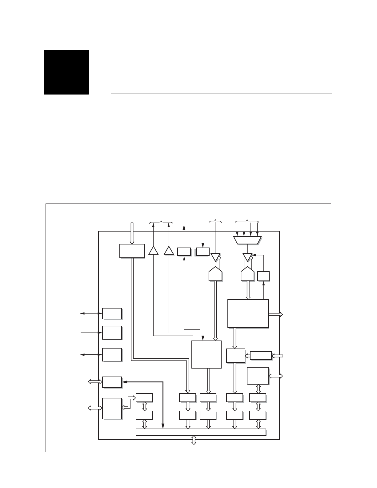
The CX25800 is implemented as a multifunction PCI bus master and fabricated in an
advanced CMOS process operating from +3.3 V I/P and 1.8 V (digital core) power
supplies. PCI inputs are +5 V and 3.3 V tolerant.
The CX25800 is designed to enable high-functionality broadcast- centric PC cards
that require high speed Input/Output (I/O) capability. This capability is necessary to
support simultaneous compressed and uncompressed digital video/audio data flows in
conjunction with hardware MPEG II/MPEG IV encoders and decoders.
Figure 1 illustrates a block diagram of the CX25800.
Figure 1. CX25800 Detailed Block Diagram
MPEG TS/
PS/LES,
Broadband Data
Broadband,
MPEG Port
Baseband
Audio
Output
Digital
Audio/
SPDIF
Output
2
I
Sout I2Sin
Digital
Audio/
SPDIF
Input
Audio
Input
Composite
Video
Video MUX
User
Configurable
1–24 GPI/O
Available
9 MBps
Bidirectional
General
Purpose
Host Port
JTAG
Clocks
and PLL
Serial
Bus
GPI/O
16-Bit
Intel/
Motorola
Host Port
DMA
16-Bit Audio DAC
16-Bit Audio DAC
PCI Bus Interface Bridge
FIFO
DMA
PCI Bus
10-Bit
ADC
Audio
Control
and
Format
Conversion
FIFO FIFO FIFOFIFO
DMA DMA DMA
10-Bit
ADC
NTSC/PAL
Decoder, Adaptive
Comb Filter and
Scaler
Pixel
Engine
AGC
Scaler
VIP 2.0
Host Port
Interface
8-Bit or 10-Bit
CCIR 656
Output
8-Bit CCIR 656
8-Bit VIP 2.0
Pixel Port
33 MBps
Bidirectional
Interface
DSH-201233A Conexant 15
7/3/07 Conexant Proprietary and Confidential

Product Overview CX25800 Data Sheet
1.2 Detailed Features
1.2.1 Analog Video Capture
1.2.1.1 Overview
The CX25800 integrates a 10-bit NTSC/PAL composite video decoder, image resizer/
scaler, Direct Memory Access (DMA) controller, and Peripheral Component Interface
(PCI) Bus master on a single device. The CX25800 can place video data directly into
host memory for video capture applications and into a target video display frame buffer
for video overlay applications. As a PCI initiator, the CX25800 can take control of the
PCI bus as soon as it is available, thereby avoiding the need for onboard frame
buffers. The CX25800 contains a pixel data First In, First Out (FIFO) to decouple the
high-speed PCI bus from the continuous video data stream. The video data input can
be scaled, color-translated, and burst-transferred to a target location on a field basis.
1.2.1.2 Input Interface
Analog video signals are input to the CX25800 through a four-input multiplexer. An
Automatic Gain Control (AGC) circuit enables the CX25800 to compensate for
nonstandard amplitudes in the analog signal input.
1.2.1.3 Image Scaler
The CX25800 can reduce the video image size in both horizontal and vertical
directions independently, using arbitrarily selected scaling ratios. The X and Y
dimensions can be scaled down to one-sixteenth of the full resolution. Horizontal
scaling is implemented with a six-tap interpolation filter, while up to five-tap
interpolation is used for vertical scaling with a line store. The video image can be
arbitrarily cropped by reducing the number of active scan lines and active horizontal
pixels per line. The CX25800 supports a temporal decimation feature that reduces
video bandwidth. This is accomplished by allowing frames or fields to be dropped from
a video sequence at fixed but arbitrarily selected intervals.
16 Conexant DSH-201233A
Conexant Proprietary and Confidential 7/3/07

CX25800 Data Sheet Product Overview
1.2.1.4 Reduced Instruction Set Computer Engine
The CX25800 enables separate destinations for the odd and even video fields, each
controlled by a pixel Reduced Instruction Set Computer (RISC) instruction list. This
instruction list is created by the CX25800 device driver and can be run in the onboard
memory or host memory. The instructions control the transfer of pixels to target
memory locations on a byte resolution basis. Complex clipping can be accomplished
by the instruction list, blocking the generation of PCI bus cycles for pixels that are not
to be seen on the display.
The DMA channels can be programmed on a field basis to deliver the video data in
packed or planar format. In packed mode, YCrCb data is stored in a single continuous
block of memory. In planar mode, the YCrCb data is separated into three streams
which are burst to different target memory blocks. Having the video data in planar
format is useful for applications where the data compression is accomplished through
software and the CPU.
1.2.1.5 UltraLock™
The CX25800 employs a proprietary technique known as UltraLock to lock to the
incoming analog video signal. It always generates the required number of pixels per
line from an analog source in which line length can vary by as much as a few
microseconds. UltraLock's digital locking circuitry enables the CX25800 to lock onto
video signals quickly and accurately, regardless of their source. Because the
technique is completely digital, UltraLock can recognize unstable signals caused by
VCR head switches or any other deviation and adapt the locking mechanism to
accommodate the source. UltraLock uses nonlinear techniques that are difficult, if not
impossible, to implement in genlock systems. And, unlike linear techniques, it adapts
the locking mechanism automatically.
1.2.1.6 Vertical Blanking Interval (VBI) Data Capture
The CX25800 provides a flexible solution for capturing and decoding disparate VBI
data types such as closed caption data, teletext, Vertical Internal Time and Control
(VITC) codes, HTML data, or multicast data. The CX25800 can operate in a VBI Line
Output mode, in which the VBI data is only captured during selected lines. This mode
of operation enables concurrent capture of VBI lines containing ancillary data and
normal video image data. In addition, the CX25800 supports a VBI Frame Output
mode in which every line in the video frame is treated as if it were a VBI line. This
mode of operation is designed for use with still-frame capture and processing
applications where sophisticated image decoding can be performed in the software
domain.
DSH-201233A Conexant 17
7/3/07 Conexant Proprietary and Confidential

Product Overview CX25800 Data Sheet
1.2.2 Analog Audio Capture
The CX25800 captures mono analog audio. The decoded audio is sample-rate
converted to a 48-kHz Pulse Code Modulation (PCM) signal to simplify processing and
interfacing. This 48-kHz stream can be routed to the built-in +85 dB Signal-to-Noise
Ratio (SNR) stereo audio Digital-to-Analog Converters (DACs) for connection to the
PC's sound card or headphones, to an external digital-audio interface, or to the PCI
bus and host for direct capture by a software audio codec.
If capture of line-level stereo audio signals is required, an inexpensive audio Analogto-Digital Converter (ADC) can be directly connected to the CX25800's I
and controlled through the serial bus master.
2
S input port
1.2.3 ITU-R 656 4:2:2 Data Output
The CX25800 provides a 27-MHz, 8- or 10-bit ITU-R 656 decoded video output
interface to allow connection of a third-party MPEG II encoder or other type of video
codec. This is useful when the host CPU is not powerful enough to perform such tasks
in software, or when high-quality encoding must be achieved.
1.2.4 ITU-R 656/VIP 2.0 Pixel Data Input
The CX25800 provides a 27-MHz, 8-bit ITU-R 656 decoded video input interface. This
allows a third-party MPEG II decoder or codec to send 4:2:2 data over the PCI bus to
a target video display frame buffer for video overlay.
1.2.5 MPEG Data Port
Channel demodulators used for digital television or broadband data applications over
terrestrial, satellite, or cable networks can be directly connected to the CX25800's
MPEG data port. As a result, transport streams can be delivered to the host for
subsequent storage to disk or software decode. Either parallel, common-interface
Digital Video Broadcasting (DVB) or serial data paths from the channel demodulator
can be supported at data transfer rates of up to 80 Mbps. If the serial interface mode is
used, the remaining unused pins on this port can be allocated as General Purpose
Input/Output (GPIO).
1.2.6 General Purpose Host Interface Port
The General Purpose Host interface allows connection of moderate-to-relatively slowspeed, third party peripherals such as infrared remote control processors, codec host
ports, smart card controllers (etc.). This port allows simultaneous connection to two
peripherals gluelessly, or to as many as four peripherals with the use of external glue
logic to provide the additional chip selects. This interface can have one upstream and
one downstream DMA channel active to or from the external peripherals at any given
time. Data bursting is not supported.
18 Conexant DSH-201233A
Conexant Proprietary and Confidential 7/3/07

CX25800 Data Sheet Product Overview
1.2.7 GPIO Port
The CX25800 provides up to 24 GPIO pins. These GPIO pins are shared with the
following pins/ports groups so that the user can determine exactly which pins can be
dedicated to specific functions versus general purpose I/O functions.
1. MPEG Parallel Data Port
2. ITU–R 656 4:2:2 Data Output
3. ITU–R 656 4:2:2 Data Input
4. Extended VIP Host Port
5. Extended General Purpose Host Port (GPHP)
1.2.8 Serial Bus Interface
The CX25800's serial bus interface supports both 99.2-kHz timing transactions and
396.8-kHz, repeated start, multibyte sequential transactions. As a serial bus master,
the CX25800 can program other devices on the video card, such as MUXs, as long as
the device address is known. The CX25800 supports multibyte sequential reads (more
than one transaction) and multibyte write transactions (greater than three
transactions), which enable communication to devices that support auto-incremental
internal addressing.
1.2.9 PCI Bus Interface
The CX25800 is designed to efficiently utilize the available 132 MBps PCI bus. The
32-bit dwords are output on the PCI bus with the appropriate image data under the
control of the DMA channels. The video stream consumes bus bandwidth with
average data rates varying from 44 MBps for full-size 768 576 PAL RGB32, to 4.6
MBps for NTSC CIF 320 240 RGB16, to 0.14 MBps for NTSC ICON 80 60 8-bit
mode.
The pixel instruction stream for the DMA channels consumes a minimum of 0.1 MBps.
The CX25800 provides the means for mitigating bandwidth bottlenecks caused by
slow targets and long bus access latencies that can occur in some system
configurations. To overcome these system bottlenecks, the CX25800 gracefully
degrades and recovers from FIFO overruns to the nearest pixel in real time.
DSH-201233A Conexant 19
7/3/07 Conexant Proprietary and Confidential
Product Overview CX25800 Data Sheet
1.3 Pin Descriptions
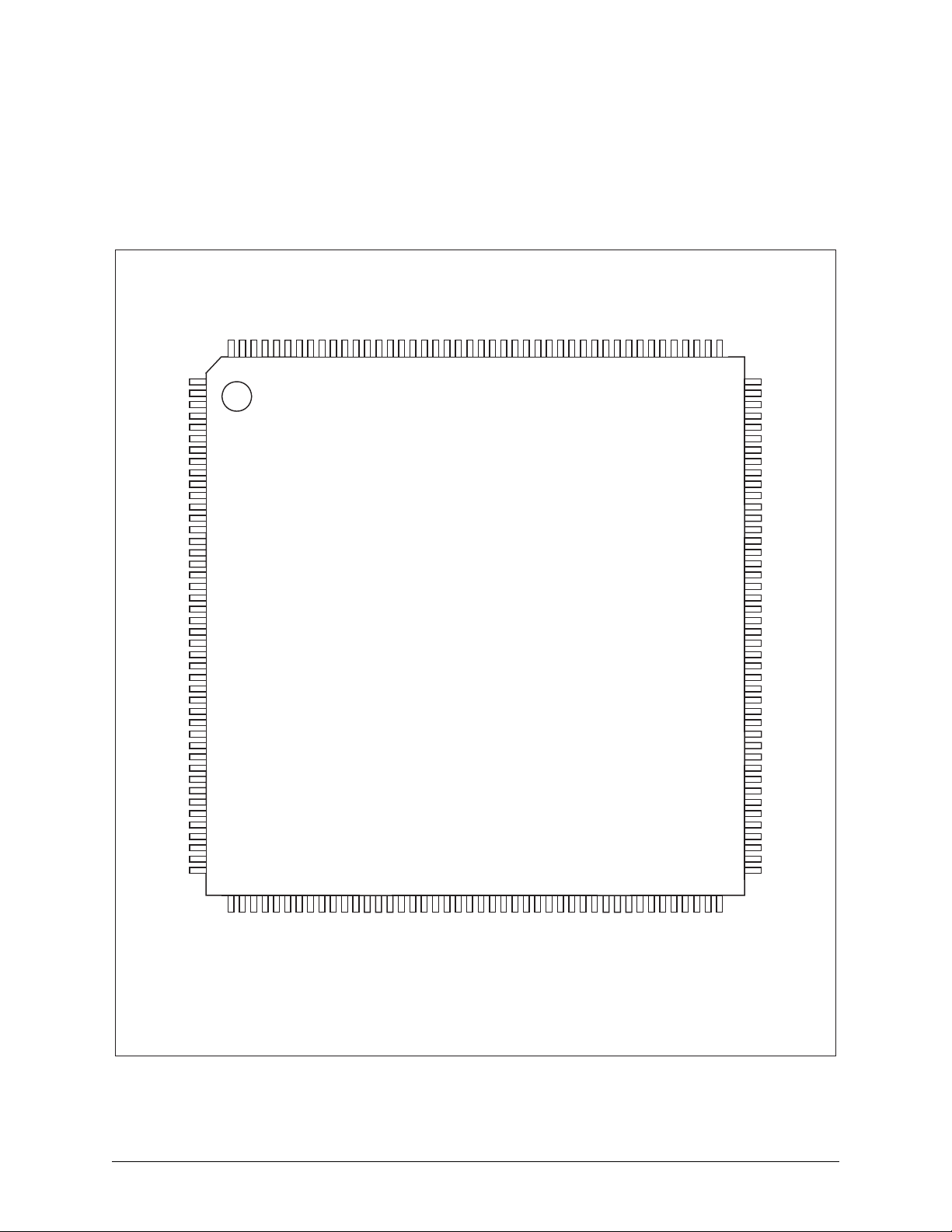
Figure 2 displays the CX25800 pinout diagram. Table 1 provides a description of pin
functions grouped by common function.
Figure 2. CX25800 Pinout Diagram
T
T
SVAL/ERR
T
T
SDAT
V
PIO
G
PIO
G
G
PIO
GPIO
PIO
G
G
PIO
PIO
G
PIO
G
HAD
V
V
HAD
V
V
V
V
AD[31]
A
A
A
A
A
A
A
BE
C
AD[23]
A
A
A
AD[19]
A
SCLK
SSOP
DDIO
V
G
[23]
[22]
[21]
[20]
[19]
[18]
[17]
[16]
HCTL
IRQ#
IPCLK
NTA
I
ST
R
EQ
R
GNT
DDIO
V
G
D
[30]
D
[29]
D[28]
D
[27]
D
[26]
D
[25]
D
[24]
[3]#
DSEL
I
D
[22]
D
[21]
D
[20]
D
[18]
G
#
RSTO
174
173
172
171
_
YS
S
170
TCKT
169
MS
168
DI
T
167
SCKO
LRCKOADATOASCKIALRCKIADATI
A
A
175
176
1
2
3
[0]
4
5
DD
6
ND
7
8
9
10
11
12
13
14
15
16
[1]
[0]
17
18
19
20
21
#
22
#
#
23
24
#
25
DD
26
27
ND
28
29
30
31
32
33
34
35
36
37
38
39
40
41
42
43
ND
44
45464748495051525354555657585960616263646566676869707172737475767778798081828384858687
2
PP
GNDAGDA
V
P
164
165
166
ACSO
L
163
1
REF
_
WM
P
162
2
REF
_
WM
P
161
ASCO
ADA
V
R
159
160
DO
_T
REFX
I
158
CR
2
AA
V
157
2
CM
V
156
2
REFP
V
155
2
REFN
BGOUT
V
V
154
153
CR
2
GA
AUDIO_IN
A
151
152
RESERVED
150
GND
V
149
GASH
A
148
AASH
V
147
SUB
A
146
1
MUX
V
145
2
MUX
V
144
3
MUX
V
143
4
MUX
V
142
CR
1
GA
A
141
1
REFN
V
140
1
REFP
V
139
1
CM
V
138
CR
1
AA
V
137
GXTL
A
136
1
T
X
135
2
T
X
134
AXTL
V
133
132
131
130
129
128
127
126
125
124
123
122
121
120
119
118
117
116
115
114
113
112
111
110
109
108
107
106
105
104
103
102
101
100
99
98
97
96
95
94
93
92
91
90
89
88
DA
S
S
CL
G
PIO
G
PIO
GPIO
G
PIO
G
PIO
G
PIO
PIO
G
G
PIO
PCLKI
G
V
DDIO
G
ND
G
PIO
G
PIO
G
PIO
PIO
G
G
PIO
PIO
G
G
PIO
PIO
G
G
PCLKO
H
AD
H
AD
AD
H
H
AD
H
AD
V
PP1
GND
P
DD
V
DDIO
V
AD
H
AD
H
H
AD
AD
H
AD
H
AD
H
AD
H
AD
H
AD
H
H
AD
AD
H
CS
H
HRD/
[0]
[1]
[2]
[3]
[4]
[5]
[6]
[7]
[8]
[9]
[10]
[11]
[12]
[13]
[14]
[15]
[0]
[1]
[2]
[3]
[4]
[5]
[6]
[7]
[8]
[9]
[10]
[11]
[12]
[13]
[14]
[15]
#
HDS
#
#
#
#
#
#
[17]
D
A
[16]
D
A
[2]#
BE
C
#
RDY
I
RAME
F
IO
DD
V
V
DDIO
V
RDY
T
TOP
S
EVSEL
D
ERR
P
#
ERR
S
#
#
[15]
D
A
[14]
D
A
[13]
D
A
LK
ND
DD
C
V
G
DDIO
V
[9]
[8]
[7]
[6]
[5]
[4]
[3]
[2]
[1]
[0]
ND
V
[12]
[11]
[10]
[0]#
D
D
D
D
D
D
D
D
D
A
A
A
A
BE
A
C
D
A
A
A
A
A
DD
D
D
D
V
G
A
A
A
AR
[1]#
P
BE
C
IO
#
DDIO
EXFB
ALE
RDY
HRW
V
/
H
H
H
WR
H
VDD: 1.8 V digit al core suppl y
Vpp,Pgnd: 1.8 V PLLs supply, ret urn
Vddio: 3.3 V di git al I/ O supp ly
Gnd: Digital core, I/O return supply
VIO: PCI 5 V d i od e cl amp su pp ly
20 Conexant DSH-201233A
Conexant Proprietary and Confidential 7/3/07

CX25800 Data Sheet Product Overview
Table 1. Pin Descriptions Grouped by Pin Function (1 of 6)
Pin Number Pin Name Dir Type Signal Description
PCI Interface (50 Pins)
63 CLK I — Clock All PCI signals except RST# and INTA# are
sampled on the rising edge of this 33.3333
MHz clock.
22 RST# I — Reset Bus reset causes all PCI outputs to
asynchronously three-state.
23 REQ# O t/s Request Agent requests bus.
24 GNT# I — Grant Agent grants bus.
37 IDSEL I — Initialization Device
Select
[28–35, 38–43,
AD[31:0] I/O t/s Address/Data Address phase when FRAME# is 1st
48, 49, 60–62,
68–72, 74–81]
[36, 50, 59, 73] CBE[3:0]# I/O t/s Bus Command/
Byte Enables
Selects device during configuration read
and write transactions.
asserted, and data transfer when IRDY#
and TRDY# are both asserted.
Bus transaction-type command during
address phase, and byte enables during
entire data phase.
58 PAR I/O t/s Parity Even parity across {AD, C/BE#}, lags
address/data phase
51 FRAME# I/O s/t/s Cycle Frame Asserted to begin bus transaction.
Deasserted when transaction in final data
phase.
52 IRDY# I/O s/t/s Initiator Ready Indicates the initiator is ready to accept read
data or has placed valid write data on the
AD.
53 TRDY# I/O s/t/s Target Ready Indicates the target is rea dy to accept write
data or has presented valid data on AD
during a read.
54 DEVSEL# I/O s/t/s Device Select Indicates the driving device has decoded
the address as the target of the current
access.
55 STOP# I/O s/t/s Stop Target requesting master to stop current
transaction.
56 PERR# I/O s/t/s Parity Error Report data parity error.
57 SERR# O t/s System Error Report address parity or system error.
21 INTA# O t/s Interrupt A Request an interrupt.
JTAG Signals (4 Pins)
DSH-201233A Conexant 21
7/3/07 Conexant Proprietary and Confidential

Product Overview CX25800 Data Sheet
Table 1. Pin Descriptions Grouped by Pin Function (2 of 6)
Pin Number Pin Name Dir Type Signal Description
169 TCK I — Test Clock Used to synchronize all JTAG test
structures. Tie low when not using JTAG.
168 TMS I r Test Mode Select Transitions drive JTAG state machine
sequence. Tie high or leave floating when
not using JTAG. A fixed sequence on this
pin initializes the JTAG tap controller.
167 TDI I r Test Data In Load input instructions and/or test vector
data for boundary scan and internal scan.
Tie high or leave floating when not using
JTAG.
158 IREFX—TDO O Test Data Out Output for verifying JTAG serial operations.
The output is three-stated when not using
JTAG port.
VIP 2.0 Host Master Signals (5 or 11 Pins)
16, 17
8–15
VHAD[1:0]
GPIO[23:16]
I/O — VIP Host Address/
Data
VIP Address and Data bus, defaults to
VIP1.1 interface with 2 addr/data pins. Can
(1)
be configured as VIP 2.0 with 8 address/
data pins (GPIO).
18 VHCTL I/O — VIP Host Control VIP System Host control
19 VIRQ# I/O od VIP Interrupt
VIP Interrupt Request (open drain)
Request
20 VIPCLK O — VIP Clock VIP master output clock. This clock is
buffered. PCI CLK = 33.3333 MHz.
Transport Stream Signals (4 or 11 Pins)
4TSDAT[0]
3 TSSOP I — Transport Stream
(2)
I — Transport Stream
Data
Start of Packet
Transport Stream Input data bus. TSDAT[0]
is used in serial mode.
Transport Stream Start-of-Packet indicator.
Indicates first byte in serial or parallel
transport packet.
2 TSVAL/ERR I — Transport Stream
Transport Stream Error or Valid indicator
Error/Valid
1 TSCLK I — Transport Stream
Clock
Transport Stream input clock. All other
transport stream inputs are sampled on the
rising (falling) edge of TSCLK.
Host Master Signals (22 Pins)
[91–101, 106–
110]
HAD[15:0] I/O — General Purpose
Host Address/Data
Bidirectional address/data access bus
90 HCS# O — General Purpose
External chip select
Host Chip Select
22 Conexant DSH-201233A
Conexant Proprietary and Confidential 7/3/07

CX25800 Data Sheet Product Overview
Table 1. Pin Descriptions Grouped by Pin Function (3 of 6)
Pin Number Pin Name Dir Type Signal Description
89 HRD#/
HDS#
O — General Purpose
Host Read/Data
Strobe
88 HALE# O — General Purpose
Host Address Latch
Enable
87 HWR/
HRW#
O — General Purpose
Host Write/Read,
not Write
86 HRDY# I r General Purpose
Host Ready
85 HEXFB I r General Purpose
Host External
Status
GPIO/Serial Bus/Reset (29 Pins)
[8–15, 112–119,
GPIO[23:0] I/O I/O GPIO See GPIO Cross-Reference Table.
123–130]
122 GPCLKI I I General Purpose
Input Clock
111 GPCLKO O O General Purpose
Output Clock
Either the active-low read signal or the
programmable polarity data strobe signal
Address Latch Enable signal, used only in
multiplexed 16-bit address/data mode
Either the active-low write signal or the
read/write bar
External data transfer acknowledge signal
Handshaking signal for use in DMA mode to
indicate the status of the external source or
destination FIFO.
Digital Video Input Reference clock
Digital Video Output Reference clock
132 SID I/O od Serial Data Bit data or acknowledge
131 SIC I/O od Serial Clock Bit clock
170 SYS_RSTO# O t/s System Reset Out Logical PCI reset, soft reset, or power-on
reset output. This is used to reset
CX25800’s peripheral under software
control or with hard reset.
Digital Audio (6 Pins)
171 ADATI I r Audio Data In Bit Serial Input data
172 ALRCKI I r Audio Left/Right
Left/Right Framing Input clock
Clock In
173 ASCKI I r Audio Serial Clock
Bit Serial Input clock
Input
174 ADATO O r Audio Data Out Bit Serial Output data
175 ALRCKO O r Audio Left/Right
Left/Right Framing Output clock
Clock Out
DSH-201233A Conexant 23
7/3/07 Conexant Proprietary and Confidential

Product Overview CX25800 Data Sheet
Table 1. Pin Descriptions Grouped by Pin Function (4 of 6)
Pin Number Pin Name Dir Type Signal Description
176 ASCKO O r Audio Serial Clock
Bit Serial Output clock
Output
Crystal Interface Signals (4 Pins)
134 XT2 O — XT2 Crystal oscillator pin
135 XT1 I — XT1 Crystal oscillator or clock oscillator input pin
can be connected to XT1.
133 VAXTL — — PSUP_XTAL XTAL and Sample and Hold digital power/
ground. Nominal VA = 3.3 V.
136 AGXTL — — NSPU_XTAL
ADC Interface (23 Pins)
[145:142] VMUX[1:4] I A Video Mux {1:4} Analog composite video inputs to the on-
chip 4:1 analog multiplexer. Leave unused
inputs No Connect. Grounding unused
inputs may draw excessive power.
150 Reserved Leave this pin No Connect
151 AUDIO IN I A Audio IN Analog audio input. Leave unused input No
Connect or connected to ground via a
decoupling capacitor. Grounding this input
may draw excessive power.
138
156
140
154
139
155
VCM1
VCM2
VREFN1
VREFN2
VREFP1
VREFP2
O A VCM_ADC{1:2} Common mode voltage reference
O A VREFN{1:2} Input Negative reference (1.0 V)—one for
each Y and C/Aud ADCs, cap to AGA.
O A VREFP{1:2} Input Positive reference (1.8 V)—one for
each Y and C/Aud ADCs, cap to AGA.
153 VBGOUT O A VBGOUT Voltage reference 1.21 V nominal, cap to
AGA.
137, 157 VAA{1:2}CR — A VAA{1:2}CR A/D core power/ground. Nominal
VA = 3.3 V
141, 152 AGA{1:2}CR — A AGA{1:2}CR
146 ASUB — — ASUB A/D core substrate (ground)
147 VAASH — — PSUPA_SHA_ADC A/D Sample and Hold Analog power/
ground. Nominal VA = 3.3 V.
148 AGASH — — NSUPA_SHA_ADC
24 Conexant DSH-201233A
Conexant Proprietary and Confidential 7/3/07

CX25800 Data Sheet Product Overview
Table 1. Pin Descriptions Grouped by Pin Function (5 of 6)
Pin Number Pin Name Dir Type Signal Description
149 VGND I A/D Virtual Ground Single-end-to-differential converter input for
common-mode noise rejection. Connect to
analog ground through 3.3 μF series
capacitor.
105, 165 VPP1/VPP2 — — VPP1, VPP2 PLL power supply. VD = 1.8 V.
104, 166 PGND — — PGND PLL return supply
158 IREFX_TDO I/O A/D IREF_EXT/TDO Shared analog current ref pin JTAG TDO
pin
Audio Output DAC Signals (6 Pins)
159 VADA — — VADA DAC analog core power and ground.
VA = 3.3 V
164 AGDA — — AGDA
163 LASCO O A LASCO DAC Pulse Width Modulator (PWM), left
stereo audio output channel
160 RASCO O A RASCO DAC PWM, right stereo audio output
channel
161 PWM_REF2 O A PWM_REF2 Audio DAC reference, right
162 PWM_REF1 O A PWM_REF1 Audio DAC reference, left
I/O and Core Power and Ground (23 Pins)
6, 26, 45, 65, 83,
103
7, 27, 44, 64, 82,
VDD — — VDD Digital core power supply. Nominal
VDD = 1.8 V.
GND — — GND Ground for digital core (GND)
120
5, 25, 46, 66, 84,
102, 121
VDDIO — — VDDI and VDDO Digital inputs/outputs power supply.
VD = 3.3 V.
47, 67 VIO — — VIO +5 V reference for 5 V-tolerant PCI input
buffers
DSH-201233A Conexant 25
7/3/07 Conexant Proprietary and Confidential

Product Overview CX25800 Data Sheet
Table 1. Pin Descriptions Grouped by Pin Function (6 of 6)
Pin Number Pin Name Dir Type Signal Description
FOOTNOTES:
(1)
VHAD[1:0] is the default for the 5-pin VIP Host Port setting.
(2)
TSDAT[0] is the default for the 4-pin serial MPEG Data Port setting. The 11-pin setting shares GPIO pins.
GENERAL NOTES:
1. Type:ractive resistive pull-up
od: open-drain
t/s: three-state
s/t/s: sustained three-state
[x:y]: Bus
{u:v:}Array of signal ports—expand to number without braces.
2. All signal I/O are LVTTL compatible (3.3 V operation with 3.9 V tolerance), except for the PCI signals which are all 5.5 V tolerant.
3. All inputs are Schmitt unless otherwise noted. The PCI inputs do not have hysteresis.
4. All outputs have drive capability I
= 4 mA unless otherwise noted.
OL
26 Conexant DSH-201233A
Conexant Proprietary and Confidential 7/3/07

2
Functional Description
2.1 Audio Input
This section describes the functionality of the analog audio input. The following
paragraphs define the logical sequence, from the audio input at the analog front end,
to the output of digital audio samples, to the PCI bus or on-board DACs.
2.1.1 Overview
Analog audio input can be output directly to the on-board DACs for connection to the
PC's sound card, to I
host for software-based playback or encoding.
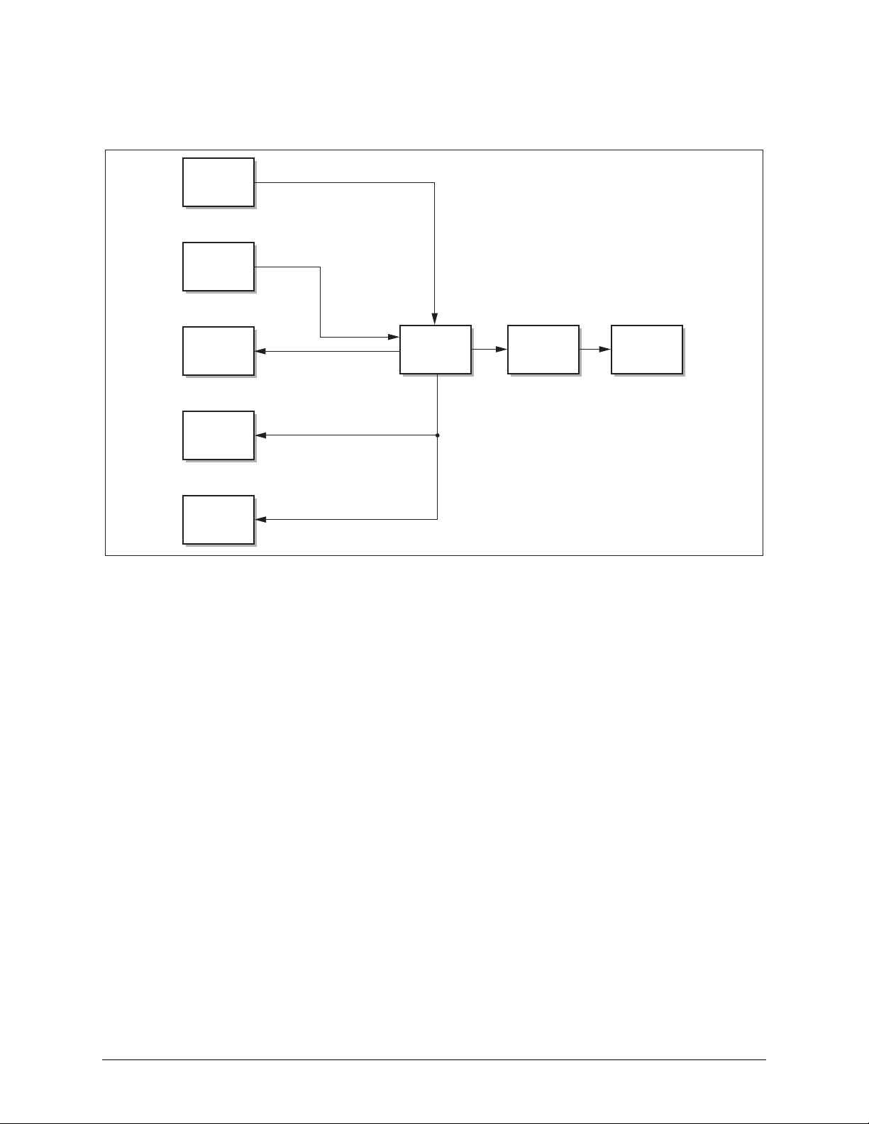
The major functional blocks of the audio subsystem are illustrated in Simplified Block
Diagram of CX25800 Audio Subsystem and are broken down into the following
sections:
Audio-ADC
Audio PLL initialization
Input source select
Dematrix control
Audio control and Sample Rate Converter
2
I
S input and output
Audio DACs
2
S for high-fidelity digital coaxial and optical interfaces, or to the
DSH-201233A Conexant 27
7/3/07 Conexant Proprietary and Confidential
Functional Description CX25800 Data Sheet
Figure 3. Simplified Block Diagram of CX25800 Audio Subsystem
Audio
ADC
2
S I n
I
2
I
S Ou t
Lef t
DAC
Ri g h t
DAC
2.1.2 Analog Input ADC
The CX2500's Audio input (pin 151) is used for sampling line level audio signals from
an amplified microphone.
2.1.3 Audio PLL Initialization
The audio PLL is automatically configured for 28.636363-MHz crystal frequency with
the AUD_INIT_LD register. If using a crystal of frequency other than 28.636363 MHz,
please contact Conexant Applications Engineering. If using the I
PLL must be programmed to exactly 221.184 MHz in fractional mode.
Audio
Co n t r o l
Audio
FI FO
DMA
2
S output mode, the
28 Conexant DSH-201233A
Conexant Proprietary and Confidential 7/3/07
CX25800 Data Sheet Functional Description
2.1.4 Input Source Select
The 12 LSBs [11:0] of the AUD_CTL register (location 24'h32058C) determine the
desired operation of the audio decoder.
24'h32058C—AUD_CTL Register
Bits Type Default Name Description
[5:0] RW 6'h00 Reserved Reserved
[6] RW 1'b0 Reserved Reserved
[8:7] RW 2'h0 Reserved Reserved
[9] RW Reserved Reserved Reserved
[10] RW 1'b0 Reserved Reserved
[11] RW 1'b0 Reserved Reserved
[12] RW 1'b0 DAC_ENABLE DAC enable bit
2
[13] RW 1'b0 I
SOUT_ENABLE I2S output enable bit
[14] RW 1'b0 I2S_STR2DAC I2S input straight to DAC enable bit
[15] RW 1'b0 I2SIN_ENABLE I2S input enable bit
2.1.5 Audio Control and Sample Rate Converter
2.1.5.1 Audio Demodulator Sample Rate Converter
Audio formats supported by the CX25800 are upconverted from their native sampled
format to 48 kHz. This simplifies internal filtering and interfacing to external hardware
peripherals through I
2.1.5.2 Volume
The volume control provides gain to both the left and right audio channel in 1 dB
increments. The volume range is –63 to 0 dB and is controlled by the VOL_CTL
register.
In addition, flexible control over muting is possible by the ability to control the muting of
the selected source from the audio demodulator, the I
During initialization, from reset to the end of the AUD_START_TIMER count, all three
of these mutes are enabled automatically to avoid pops or clicks on any of the output s.
2
S, the internal audio DACs, or to software codecs.
2
S output, and the audio DAC.
DSH-201233A Conexant 29
7/3/07 Conexant Proprietary and Confidential
Functional Description CX25800 Data Sheet
24'h320594—VOL_CTL Register
Bits Type Default Name Description
[5:0] RW 8'h00 VOLUME Volume control in dB steps, 0 to –63 dB
[6] RW 1'b0 SRC_MUTE_EN Source mute enable
[7] RW 1'b0 I2S_MUTE_EN I2S mute enable
[8] RW 1'b0 DAC_MUTE_EN DAC mute enable
[15:9] RW 7'h00 — Reserved
2.1.5.3 Balance
The DAC output level can be adjusted. Digital balance control is used to alter the
relative gain between the left and right channel outputs. Balance is controlled by
providing an attenuation to one channel while maintaining 0 dB gain to the other
channel. Attenuation of either channel is in the range of -63 to 0 dB in 1 dB steps.
Balance attenuation is performed prior to the volume control. Stereo is only available
2
S input. The analog audio input is monophonic.
via I
24'h320598—BAL_CTL Register
Bits Type Default Name Description
[5:0] RW 8'h00 BAL_LEVEL Attenuation to be provided to the selected channel in dB. Range
is 0 to –63 dB.
[6] RW 1'b0 BAL_RIGHT Select right channel for balance control if 1, select left channel if
0.
[15:7] RO 7'h00 — Reserved
30 Conexant DSH-201233A
Conexant Proprietary and Confidential 7/3/07
 Loading...