

Page 1
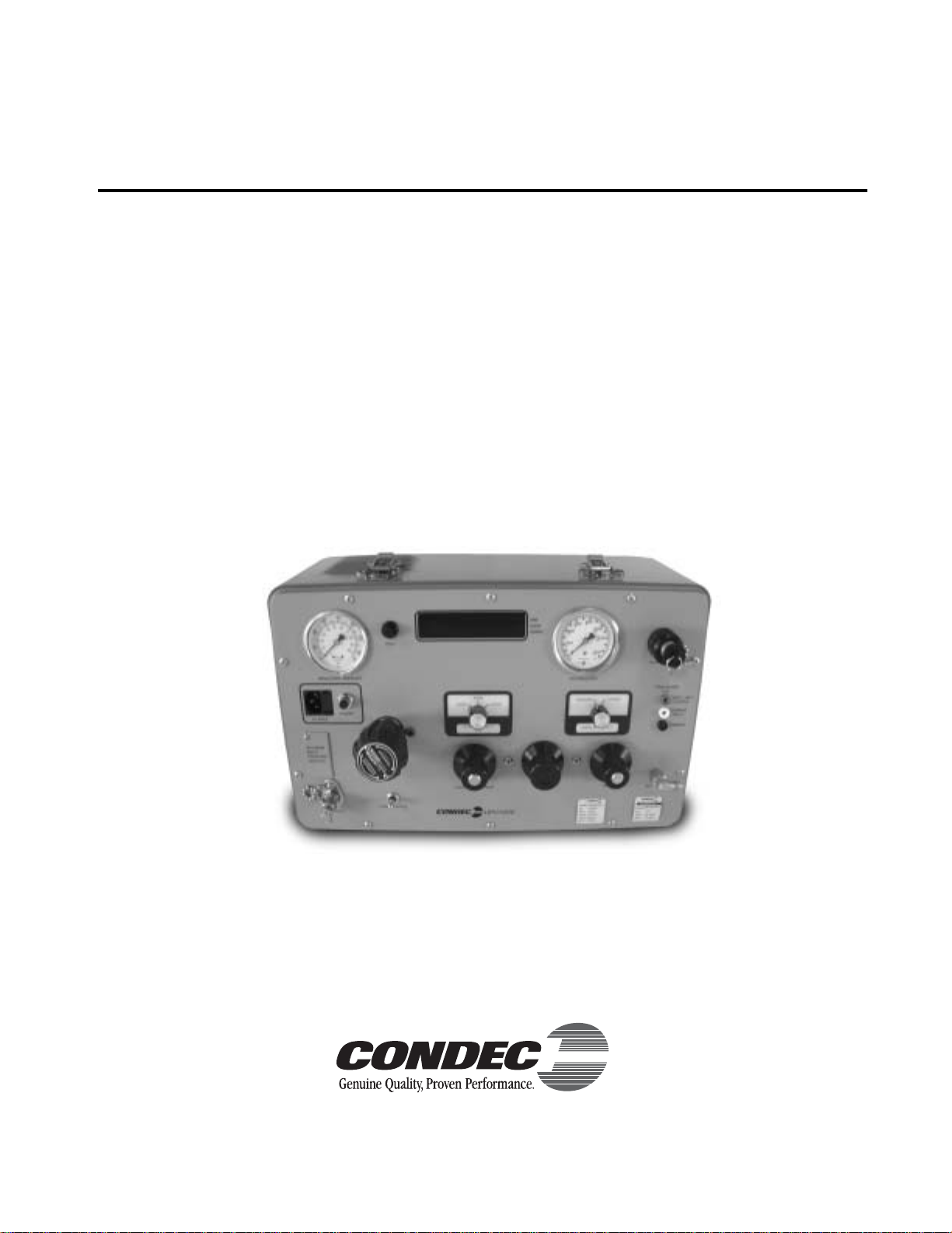
UPC5200 & UPC5210
Portable & Rack-mountable Pneumatic
High Pressure Calibration Console
Operation and Maintenance Manual
CONDEC Sales Phone No. (888) 295-8475
CONDEC Web Site: www.4condec.com
63259
Page 2

Contents
About This Manual................................................................................................................................... 1
1.0 Introduction.................................................................................................................................. 1
2.0 Operation...................................................................................................................................... 4
2.1 Pressure Cylinder (PN 59533) Filling Procedure . . . . . . . . . . . . . . . . . . . . . . . . . . . . . . . . . . . . . . . . . 4
2.2 Initial Setup Procedure. . . . . . . . . . . . . . . . . . . . . . . . . . . . . . . . . . . . . . . . . . . . . . . . . . . . . . . . . . . . 4
2.3 Pressure Measurement Sequence (Gage Only) . . . . . . . . . . . . . . . . . . . . . . . . . . . . . . . . . . . . . . . . . 5
2.4 Pressure Measurement Sequence (Absolute Only). . . . . . . . . . . . . . . . . . . . . . . . . . . . . . . . . . . . . . . 6
3.0 Calibration.................................................................................................................................... 9
3.1 Pneumatic Calibration Set-Up . . . . . . . . . . . . . . . . . . . . . . . . . . . . . . . . . . . . . . . . . . . . . . . . . . . . . . 9
3.2 Instrument Calibration Set-Up . . . . . . . . . . . . . . . . . . . . . . . . . . . . . . . . . . . . . . . . . . . . . . . . . . . . . . 9
3.3 Zero/Span Calibration . . . . . . . . . . . . . . . . . . . . . . . . . . . . . . . . . . . . . . . . . . . . . . . . . . . . . . . . . . . 10
3.4 Linearity and Hysteresis Calibration . . . . . . . . . . . . . . . . . . . . . . . . . . . . . . . . . . . . . . . . . . . . . . . . . 10
3.5 Shunt Resistor Calibration . . . . . . . . . . . . . . . . . . . . . . . . . . . . . . . . . . . . . . . . . . . . . . . . . . . . . . . . 12
3.6 Current Input Calibration . . . . . . . . . . . . . . . . . . . . . . . . . . . . . . . . . . . . . . . . . . . . . . . . . . . . . . . . . 12
3.7 Permanent Data Storage . . . . . . . . . . . . . . . . . . . . . . . . . . . . . . . . . . . . . . . . . . . . . . . . . . . . . . . . . 12
3.8 Normal Mode Test. . . . . . . . . . . . . . . . . . . . . . . . . . . . . . . . . . . . . . . . . . . . . . . . . . . . . . . . . . . . . . 13
3.9 Self-Check Test. . . . . . . . . . . . . . . . . . . . . . . . . . . . . . . . . . . . . . . . . . . . . . . . . . . . . . . . . . . . . . . . 13
4.0 Maintenance & Service............................................................................................................. 14
4.1 Troubleshooting. . . . . . . . . . . . . . . . . . . . . . . . . . . . . . . . . . . . . . . . . . . . . . . . . . . . . . . . . . . . . . . . 14
4.2 Maintenance & Service Procedures . . . . . . . . . . . . . . . . . . . . . . . . . . . . . . . . . . . . . . . . . . . . . . . . . 14
4.2.1 Panel/Chassis Removal and Installation . . . . . . . . . . . . . . . . . . . . . . . . . . . . . . . . . . . . . . . . . . . . . . . 16
4.2.2 Accumulator, Intensifier & ORION-3A (PN 55287) Removal. . . . . . . . . . . . . . . . . . . . . . . . . . . . . . . . . 16
4.2.3 ORION-3A Manifold, Valve Seat Removal . . . . . . . . . . . . . . . . . . . . . . . . . . . . . . . . . . . . . . . . . . . . . . 17
4.2.4 ORION-3A Manifold, Vernier Control Disassembly. . . . . . . . . . . . . . . . . . . . . . . . . . . . . . . . . . . . . . . . 18
4.2.5 ORION-3A Manifold, Vernier Control Reassembly. . . . . . . . . . . . . . . . . . . . . . . . . . . . . . . . . . . . . . . . 18
4.2.6 ORION-3A Manifold, Valve Seat Installation. . . . . . . . . . . . . . . . . . . . . . . . . . . . . . . . . . . . . . . . . . . . . 19
4.2.7 Accumulator, Intensifier and ORION-3A Manifold, Panel Installation . . . . . . . . . . . . . . . . . . . . . . . . . . 20
4.2.8 ORION-3A Manifold, Valve Adjustment Procedure . . . . . . . . . . . . . . . . . . . . . . . . . . . . . . . . . . . . . . . 20
4.2.9 Accumulator Assembly, O-ring (PN 58051) Replacement, Filter (PN 56993) Cleaning. . . . . . . . . . . . . 21
4.2.10 Intensifier Assembly, O-rings/Seals Replacement . . . . . . . . . . . . . . . . . . . . . . . . . . . . . . . . . . . . . . . . 22
4.2.11 Regulator (Standard Pneumatic) and Solenoid Removal . . . . . . . . . . . . . . . . . . . . . . . . . . . . . . . . . . . 25
4.2.12 Regulator (Standard Pneumatic) and Solenoid Installation. . . . . . . . . . . . . . . . . . . . . . . . . . . . . . . . . . 25
4.2.13 Regulator (Tescom) and Solenoid Removal. . . . . . . . . . . . . . . . . . . . . . . . . . . . . . . . . . . . . . . . . . . . . 26
4.2.14 Regulator (Tescom) and Solenoid Installation . . . . . . . . . . . . . . . . . . . . . . . . . . . . . . . . . . . . . . . . . . . 26
4.2.15 Panel Gauge Removal and Installation . . . . . . . . . . . . . . . . . . . . . . . . . . . . . . . . . . . . . . . . . . . . . . . . 27
4.2.16 Test Port Quick-Connect Fitting (PN 59004) and Filter (PN 54188), Removal and Installation . . . . . . . 28
4.2.17 Test Port (output) Hose Quick-Connect Fitting and Filter (PN 56991), Removal and Installation. . . . . . 28
4.2.18 Input Port Filter (PN 54188), Removal and Installation. . . . . . . . . . . . . . . . . . . . . . . . . . . . . . . . . . . . . 29
4.2.19 Input Port Hose Quick-Disconnect Female Fitting, Removal and Installation . . . . . . . . . . . . . . . . . . . . 29
4.2.20 AC Fuse (PN 57472), Removal and Installation . . . . . . . . . . . . . . . . . . . . . . . . . . . . . . . . . . . . . . . . . . 30
4.2.21 Panel Mounted AC Power/EMI Line Filter (PN 58870), Removal and Installation . . . . . . . . . . . . . . . . . 30
4.2.22 Chassis Mounted EMI Line Filter (PN 59015), Removal and Installation. . . . . . . . . . . . . . . . . . . . . . . . 30
4.2.23 Pump Control Switch (PN 60307), Removal and Installation . . . . . . . . . . . . . . . . . . . . . . . . . . . . . . . . 31
4.2.24 Power Switch (PN 58878), Removal and Installation . . . . . . . . . . . . . . . . . . . . . . . . . . . . . . . . . . . . . . 31
4.2.25 Range Select Switch (PN 55924) and Display Select Switch (PN 55933), Removal and Installation. . . 32
4.2.26 Zero Switch (PN 58886), Removal and Installation . . . . . . . . . . . . . . . . . . . . . . . . . . . . . . . . . . . . . . . 32
4.2.27 CPU Assembly, Removal and Installation . . . . . . . . . . . . . . . . . . . . . . . . . . . . . . . . . . . . . . . . . . . . . . 33
4.2.28 Pump Control Board Assembly, Removal and Installation . . . . . . . . . . . . . . . . . . . . . . . . . . . . . . . . . . 33
4.3 ORION-3A Valve Assembly (55287) Parts List . . . . . . . . . . . . . . . . . . . . . . . . . . . . . . . . . . . . . . . . . 34
4.4 Intensifier Assembly Parts List . . . . . . . . . . . . . . . . . . . . . . . . . . . . . . . . . . . . . . . . . . . . . . . . . . . . . 36
Copyright © 2002 Rice Lake Weighing Systems. All rights reserved. Printed in the United States of America.
Specifications subject to change without notice.
February 2002
Page 3

5.0 Model Number System .............................................................................................................. 44
6.0 Ranges and Resolutions ............................................................................................................ 45
7.0 Options, Replacement Kits ........................................................................................................ 46
8.0 Specifications............................................................................................................................ 47
UPC5200/UPC5210 Warranty and Return Policy................................................................................... 49
UPC5200/UPC5210 Return Material Authorization Form....................................................................... 50
Page 4

About This Manual
This manual is intended for use by service technicians
responsible for installing and servicing
UPC5200/UPC5210 pressure calibrators.
The UPC5200 portable pneumatic pressure calibrator
and the rack-mounted UPC5210 are rugged, compact
instruments manufactured by Condec. They are
designed to provide superior accuracy, range of
calibration and ease of operation when used for the
calibration of a wide variety of pressure sensing and
measuring devices.
This manual has been written to give the user a simple
and clear explanation of how to operate, calibrate and
maintain these instruments.
Warning
system. It is strongly recommended that only personnel
formally trained in the use of pneumatic pressure
equipment be permitted to operate it. Potentially
dangerous conditions can be produced through negligent
handling or operation of the console due to the high
pressure cylinder contained within the unit.
These units are strictly for use with pneumatic pressures.
Erroneous readings and potential damage can result from
the introduction of hydraulic fluids into the internal tubing
lines.
Before attempting to use either style
pressure calibrator, the following
instructions must be carefully read
and understood by personnel using
the equipment. This is a high-pressure
Authorized distributors and their
employees can view or download this
manual from the Condec distributor site
at
www.4condec.com
.
1.0 Introduction
The UPC5200/UPC5210 pressure calibrators utilize an extremely repeatable sensor coupled to
microprocessor-based electronic circuitry and a selectable units display system. This provides easily readable
and accurate digital representation of the measured pressure. This all electro-mechanical device utilizes our
precision Orion-3A vernier, which has one test port. Front panel gages tell the operator accumulator pressure, as
well as regulated input pressure. The pressure regulator acts as a pressure limiter so that the operator can adjust
input system pressure to 1/10 of the target value. Fill and test hoses are supplied for the customer. Standard front
panel buttons and switches provide selection of the desired pressure range, push-button zeroing and the unique
internal self-check feature. For field use, the UPC5200 has a separate 83.3 cubic foot, 2,216 psi cylinder to
provide many hours of use.
Utilizing microprocessor technology , the UPC5200 and rack-mounted UPC5210 instruments of fer a combination
of features, performance, versatility and reliability not previously available in a single, self-contained pressure
calibration instrument. Some of the features are listed below:
• Three independent switch-selectable pressure ranges per instrument.
•Accuracy of each range equal to or better than ±0.05% Full Scale.
•Both gage and absolute pressure calibration models are available.
•Automatic self-check: Computer-controlled internal circuitry provides automatic maintenance of both zero
and span calibration data to insure long-term stability and accuracy.
•Digital Display: Eliminates parallax, interpolation and operator judgement errors. Large, bright, red LED.
digits provide excellent readability under all lighting conditions (also available with an LCD).
•Using a manually adjustable regulator, the maximum system input pressure is adjusted to any desired value
higher (typically 20 to 50%) than the full scale range of the device being tested. By virtue of this technique,
the unit under test is fully protected from being inadvertently over-pressurized.
• Portable: These compact, self-contained systems are easily carried and operated by only one person. Total
weight is approximately 50 lbs.
• System Calibration: The instruments may be completely calibrated without being removed from the
external case. A separate plug-in calibration console (PN 60109) provides access to the computer when
calibration is to be performed. No manual alignment or potentiometer adjustments are required.
Introduction
1
Page 5

2
•Calibration Integrity: Tamper-proof design. Once calibrated, numerous safeguards guarantee the integrity
of pressure readings obtained. Display prompting provides the operator with functional status information
during both operation and calibration.
• Pressure Source (UPC5200 only): An external supply cylinder with a volume of 83.3 std. cu. ft. of N
provides up to 2,216 psig of pressure for calibration and test. This pressure source drives a pneumatically
operated 10 to 1 intensifier contained within the UPC5200. Therefore, a 1,000 PSI input is amplified to
10,000 PSI.
• Simple Operation: All controls, indicators and pressure ports are accessible from the front panel.
Accompanying operator's manual provides clear, concise instructions for system operation.
•Data Input Capability: A front panel-mounted connector and selector switch permit the 4-20 mA current
signal from the gauge-under-test or voltage to be displayed. Transducer excitation voltage of 28 VDC is
provided standard.
• Safe, Clean Operation: All pressure components are made of stainless steel and proof-tested to at least
150% of maximum operating pressure. In addition, the system contains a high-pressure burst disk to
protect both the operator and system components from harm in the event of inadvertent o v er -pressurization.
The heart of this calibration system is a highly stable and repeatable pressure transducer. These sensors produce
an electrical output signal which is linearly proportional to the applied pressure. By combining the sensors with
sophisticated microprocessor-based circuitry, an even higher degree of operational accuracy and precision has
been accomplished. For example, computer-generated correction curves for both the non-linearity and the
hysteresis of the sensors improve these characteristics by an order of magnitude or more. In addition, a self-check
feature ensures long-term accuracy by utilizing the computer to generate and control an internal shunt calibration
mode of operation. The indicators full-scale reading is compared against, and if necessary, corrected to the
digitally-stored value for full scale obtained at the time of initial pressure calibration.
2
In addition to the features, the UPC5200/UPC5210 pressure calibrator is easy to use. Two micro-metering valves
and vernier are provided to control the internally intensified nitrogen while the digital display indicates precisely
the magnitude of the applied test pressure. Also, a simple push-button switch provides zeroing of the pressure
display. The
selection, as well as,
Range
Pressure
and
Current
display selections are accomplished via a pair of
clearly marked rotary switches. Over-pressure protection is provided through a fully-adjustable pressure
regulator, which is manually set for each new device being tested.
With respect to calibration, the instruments have been designed and programmed to provide the operator with
various prompting symbols and legends during each phase of the calibration sequence. Also, to prevent
unauthorized tampering or calibrations, programming or calibration can only be achieved with the aid of a
separate, plug-in calibration console (PN 60109). Also, the electronic circuitry has been designed without any
potentiometers or adjustments, eliminating the possibility of unwanted changes. Finally, the computer has been
programmed with a series of internal self-diagnostic routines which continually monitor and check every bit of
data stored and processed by this system. The computer immediately notes or shuts down operation in the event
of an out-of-tolerance reading or any outright failures.
UPC5200/UPC5210 Operation and Maintenance Manual
Page 6
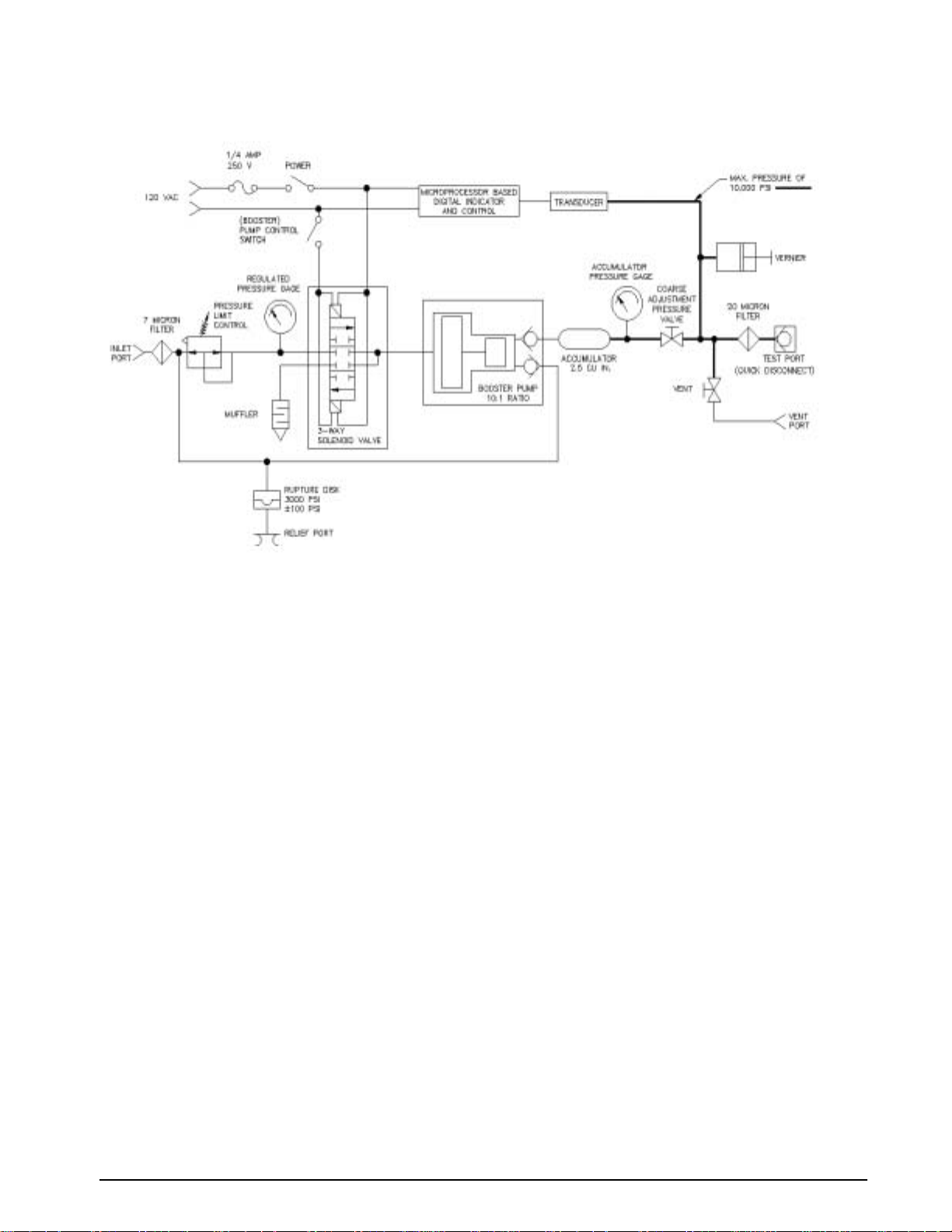
Figure 1-1 provides an overview of the UPC5200/UPC5210’s function.
Figure 1-1. UPC5200/UPC5210 Flow Diagram
Introduction
3
Page 7

4
2.0 Operation
2.1 Pressure Cylinder (PN 59533) Filling Procedure
NOTE: Condec strongly recommends that the external nitrogen supply cylinder be pressure-tested and re-certified
every five years from date cylinder was manufactured per U.S. DOT. 3AL Regulation, Title 49 CFR, parts 173 and 178.
To initially fill or refill the external pressure cylinder (2,216 PSI max.), proceed as described below.
1. Close the
CYLINDER
valve by rotating clockwise until it stops.
2. Connect the customer supplied fill hose, to a clean regulated nitrogen source, with an output pressure
gauge and vent valve.
3. Connect the other end of the customer supplied fill hose to the female CGA-580 brass
CYLINDER
fitting.
4. Open the
CYLINDER
valve by rotating counter-clockwise until it stops.
5. Slowly open the valve on the nitrogen source and allow the gas to flow into the pressure cylinder. The
customer supplied output pressure gauge indicates the amount of pressure within the internal cylinder.
NOTE: Cylinder is equipped with a rupture disk.
6. Use the following procedure to fill the cylinder:
a) Fill cylinder to 1,000 PSI at a rate of charge equal to a minimum of two minutes, then wait five
minutes for system to stabilize.
b) Fill cylinder from 1,000 PSI to 2,216 PSI at a rate of charge equal to a minimum of two minutes.
c) Wait five minutes for cylinder to stabilize before using.
7. Close the
CYLINDER
valve by rotating clockwise until it stops.Vent nitrogen source and remove fill hose.
2.2 Initial Setup Procedure
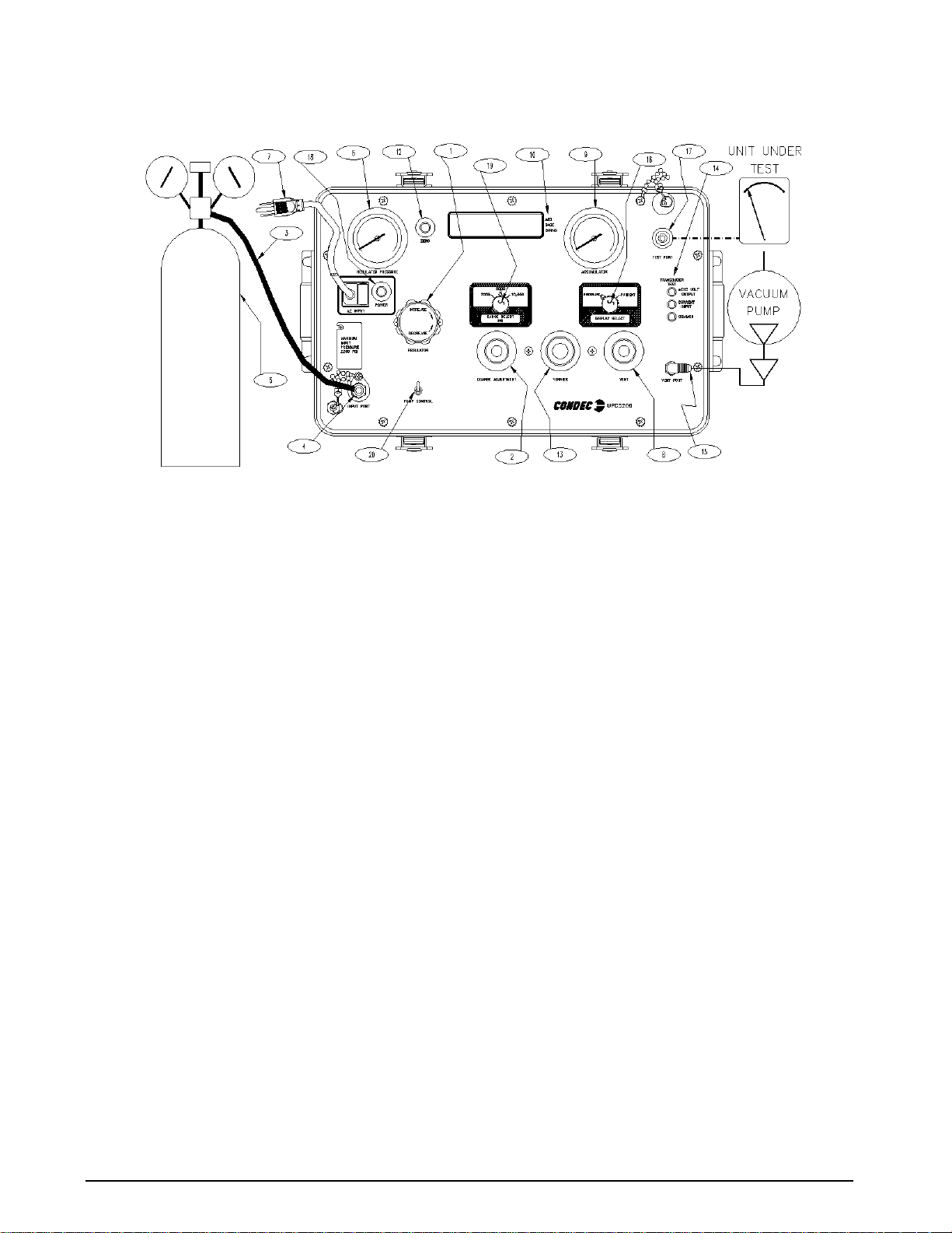
To prepare for actual calibration usage, see Figure 2-1 below and proceed as follows:
1. Check that the
COARSE ADJUSTMENT
Vent valve (8) is open (two turns counter-clockwise from its stop). Verify that the REGULATOR (1) is
closed (rotate counter-clockwise until it stops).
2. Plug in the power cord (7) and energize the unit by depressing the
UPC5200/UPC5210 performs an internal functional self-check. Allo w at least 10 minutes warm-up time.
3. Select the desired full scale pressure range via the three-position rotary switch (19). For the best
accuracy, the selected range must be greater than, but close as possible to, the full scale range of the
device-under-test.
NOTE: Do not switch pressure ranges during a calibration cycle.
4. Set the
DISPLAY SELECT
switch (16) to the PRESSURE position.
5. Connect the male end of the test hose to the TEST PORT (17) fitting.
6. Connect the swivel fitting end (7/16-20) of the test (output) hose to the device-under-test using adapters
if required. Tighten all connections properly.
7. UPC5200: Connect the male end of the input hose (3) to the female CGA-580 brass
fitting.
valve (2) is closed (rotate clockwise until it stops) and that the
POWER
switch (18). The
CYLINDER
valve
(5) valve
UPC5210: Connect the male end of the input hose (3) to the female CGA-580, customer supplied,
pressure source.
8. Connect the swivel fitting end (7/16-20) of the input hose (3) to the INPUT PORT (4) fitting. Tighten all
connections properly.
UPC5200/UPC5210 Operation and Maintenance Manual
Page 8
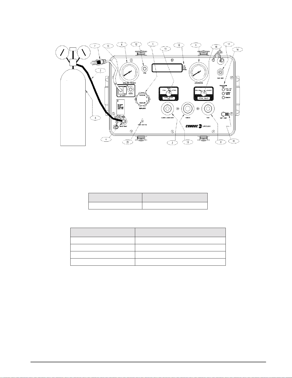
Figure 2-1. Initial Setup Procedure
NOTE: UPC5200 shown, AC Input (7) and Input Port (4) are on back side of UPC5210 Rack Mountable Calibrator.
9. Optional - if the current (4.000 to 20.000 mA) measurement features are to be used, connect the
provided Transducer Test Cable (PN 55092) to the Transducer Test Jacks (14).
When connected, this cable provides +28 VDC e xcitation. The internal impedance (load) is 10 ohms. The display
scaling for these current measurements are as follows:
SWITCH POSITION
Current 0-20.000 mA by 0.005 mA
Table 2-1. Display Select Switch (16)
DISPLAY READING
The test cable connector wiring is as follows:
CONNECTOR PIN DESIGNATION FUNCTION
A+ VDC
B+ SIGNAL
C NOT USED
D VOLTAGE & SIGNAL COMMON
Table 2-2. Transducer Test Cable (PN 55092)
NOTE: Connector pin designations are for reference only, and are no longer a connector on newer units. See Figure 2-1
on page 5 (14).
2.3 Pressure Measurement Sequence (Gage Only)
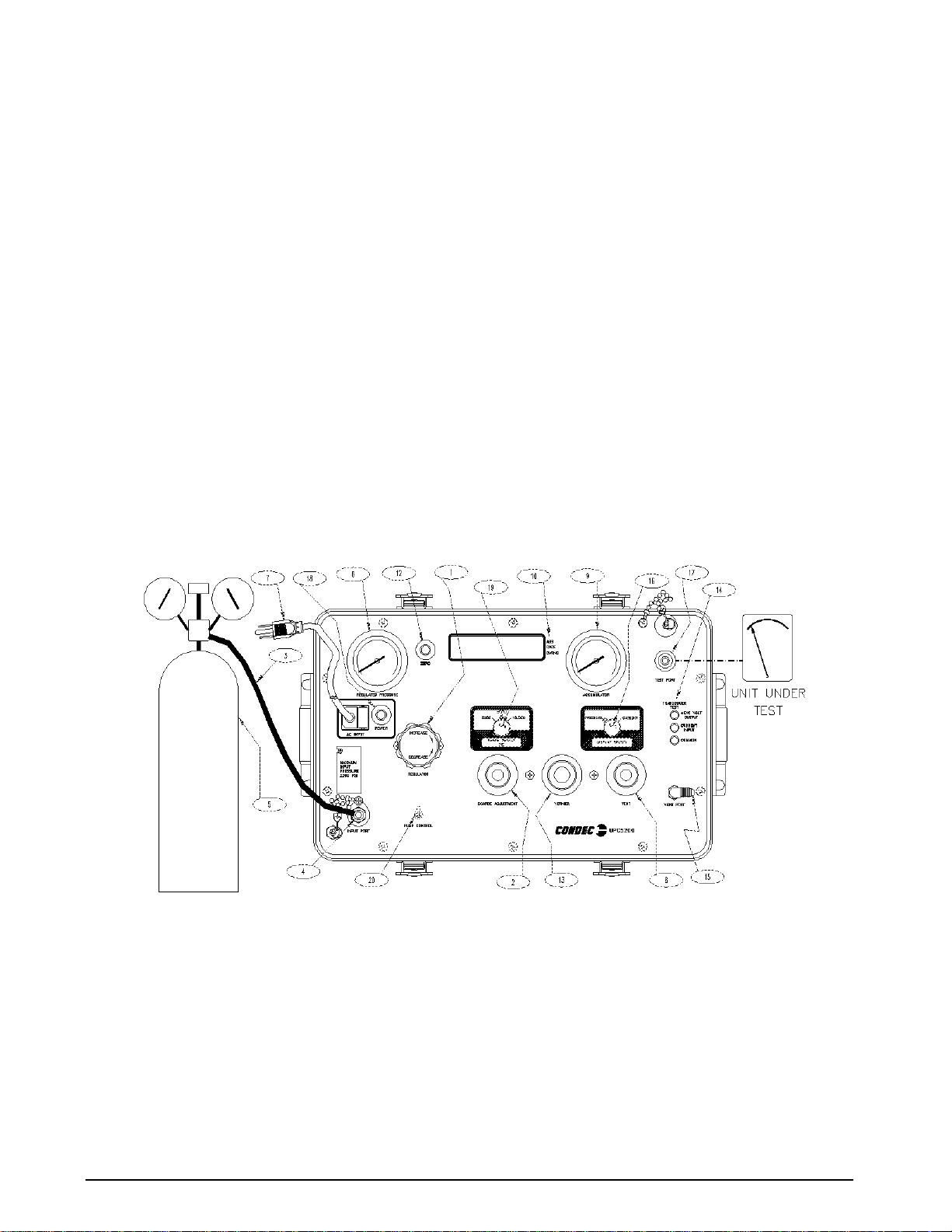
NOTE: See Figure 2-2 on page 6, when following these steps.
1. Note that the indicator on the right end of the display indicates GAGE mode (10).
2. Zero unit by depressing the
any time, as long as the VENT valve (8) is open, by depressing the
NOTE: If ZERO switch is depressed longer than 5 seconds unit will perform an internal, functional self-check.
3. UPC5200: Open the cylinder valve (5) by rotating counter-clockwise slowly until it stops.
UPC5210: Open the, customer supplied, pressure source valve.
switch (12) for less than five seconds. The instrument can be zeroed at
ZERO
switch (12).
ZERO
Operation
5
Page 9
6
4. Using the REGULATOR (1), adjust the maximum intensifier pump input pressure, as read by the
REGULATED PRESSURE gauge (6), to 1/10 of the full-scale range of the device-under-test. The unit
utilizes an internal intensifier with a 10:1 ratio. As an example, setting regulated pressure to 300 PSI
would generate an output pressure of 3,000 PSI. Using this technique, the device under test is fully
protected from being accidentally over-pressurized.
5. To generate pressure, enable the
PUMP CONTROL
the ACCUMULATOR gauge (9). Turn the
PUMP CONTROL
switch (20) and monitor the pressure as it builds in
switch (20) off when 10% more than the
target pressure has been achieved.
NOTE: The intensifier PUMP CONTROL switch (20) can be operated in two modes. The up position is
continuous and the down position is momentary/jog.
6. To apply pressure, the
VENT
valve (8) must remain closed. Open the
COARSE ADJUSTMENT
valve (2),
approximately 1/2 turn counter-clockwise, until the numerical display begins to move. In general, the
pressure may be changed rapidly until reaching approximately 90% of the desired final value.
7. Use either the
COARSE ADJUSTMENT
(2) or
valve (8) to obtain a specific pressure reading. Both
VENT
provide precise control. As the pressure approaches the desired value, the valve being used for control
should be rotated slowly clockwise to its closed position. With a little experience, pressure values very
close to the desired final value may be quickly achieved.
NOTE: Use the intensifier PUMP CONTROL switch if the ACCUMULATOR gauge (9) reading falls below
required target pressure value.
8. To obtain exact pressure readings, slowly rotate the
VERNIER
control (13) knob in the direction required
(clockwise to increase pressure) as indicated by the electronic numerical display.
9. Transducer Current Measurement - the current signal from the transducer may be displayed at any time
simply by placing the
DISPLAY SELECT
switch (16) to its CURRENT position.
Figure 2-2. Pressure Measurement Sequence (Gage Only)
NOTE: UPC5200 shown, AC Input (7) and Input Port (4) are on back side of UPC5210 Rack Mountable Calibrator.
2.4 Pressure Measurement Sequence (Absolute Only)
NOTE: See Figure 2-3 on page 8, when following these steps.
1. Note that the indicator on the right end of the display indicates ABSOLUTE mode (10).
2. If only pressure measurements greater than barometric are required, continue to step 2.1. If pressure
measurements below atmospheric pressure are required go to step 3.
2.1. UPC5200: Open the cylinder valve (5) by rotating counter-clockwise slowly until it stops.
UPC5210: Open the pressure source valve (customer supplied).
UPC5200/UPC5210 Operation and Maintenance Manual
Page 10

2.2. Using the REGULATOR (1), adjust the maximum intensifier pump input pressure, as read by the
REGULATED PRESSURE gauge (6), to 1/10 of the full-scale range of the device-under-test. The
unit utilizes an internal intensifier with a 10:1 ratio. As an example, setting regulated pressure to 300
PSI would generate an output pressure of 3,000 PSI. Using this technique, the device under test is
fully protected from being accidentally over-pressurized.
2.3. To generate pressure, enable the
PUMP CONTROL
in the ACCUMULATOR gauge (9). Turn the
switch (20) and monitor the pressure as it builds
PUMP CONTROL
switch (20) off when 10% more
than the target pressure has been achieved.
2.4. To apply pressure, close the VENT valve (8) approximately two turns to its stop and open the
COARSE ADJUSTMENT valve (2) approximately 1/2 turn counter-clockwise until the numerical
display begins to move. In general, the pressure may be changed rapidly until reaching
approximately 90% of it desired final value.
2.5. Use either the COARSE ADJUSTMENT (2) or VENT valve (8) to obtain a specific pressure
reading. Both provide precise control. As the pressure approaches the desired value, the valve being
used for control should be rotated slowly clockwise to its closed position. With a little experience,
pressure values very close to the desired final value may be quickly achieved.
NOTE: Use the intensifier PUMP CONTROL switch if the ACCUMULATOR gauge (9) reading falls below
required target pressure value.
2.6. To obtain exact pressure readings, slowly rotate the VERNIER control (13) knob in the direction
required (clockwise to increase pressure) as indicated by the electronic numerical display.
3. If pressure measurements below atmospheric pressure are required, connect a vacuum pump to the
VENT/VACUUM port (15) as shown in Figure 2-3 on page 8.
3.1. Open the VENT valve (8), but the COARSE ADJUSTMENT valve (2) must remain closed. Apply
power to the vacuum pump and allow it to evacuate the system for several minutes or until the
digital display reading reaches equilibrium near 0 PSIA. Press the
button to establish a zero
ZERO
reference on the display.
3.2. With the vacuum pump still running, close the VENT valve (8) and check for system leaks. If there
are none, continue to step 3.3.
3.3. Remove the vacuum pump.
3.4. To apply vacuum, COARSE ADJUSTMENT (2) valve must remain closed. Open the VENT valve
(8) counter-clockwise slowly until the numerical display begins to move.
3.5. As the pressure approaches the desired value, the VENT valve (8) should be rotated slowly
clockwise to its closed position. With a little experience, pressure values very close to the desired
final value may be quickly achieved.
3.6. To obtain exact PSIA readings, slowly rotate the VERNIER control (13) knob in the direction
required (clockwise to increase pressure) as indicated by the electronic numerical display.
4. Transducer Current Measurement - the current signal from the transducer may be displayed at any time
simply by placing the
DISPLAY SELECT
switch (16) to its CURRENT position.
Operation
7
Page 11
8
Figure 2-3. Pressure Measurement Sequence (Absolute Only)
NOTE: UPC5200 shown, AC Input (7) and Input Port (4) are on back side of UPC5210 Rack Mountable Calibrator.
UPC5200/UPC5210 Operation and Maintenance Manual
Page 12
3.0 Calibration
Follow the procedure on the following pages for calibrating the UPC5200/UPC5210.
NOTES:
• When calibrating, the computer within the UPC5000/UPC5010 is actually being re-programmed, therefore it is
important that the pressure standard being used is in satisfactory operating condition and that the technician
fully understands its operating characteristics and methods of usage. In addition, the UPC5000/UPC5010 itself
must be properly warmed up (approximately 10 minutes) and electrically stabilized prior to performing a
calibration cycle.
• The Condec Repair Lab is equipped to do calibrations on Condec calibrators and pressure standards.
Calibrations include a certification and are traceable to N.I.S.T (see “UPC5200/UPC5210 Return Material
Authorization Form” on page 50).
3.1 Pneumatic Calibration Set-Up
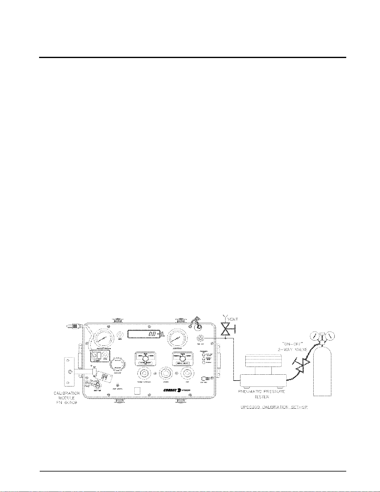
A typical GAGE calibration set-up using a floating piston type dead weight tester is shown in Figure 3-1. While
doing an ABSOLUTE only unit calibration, a vacuum pump with a PSIA test standard is required where the dead
weight tester/pressure source is shown in Figure 3-1. This enables going below local barometric pressure.
NOTE: Any type of precision pressure or vacuum standard is acceptable as long as its basic accuracy is ±0.025% of
point or better.
To permit proper calibration, at least an ON/OFF and a VENT valve (connected as shown in Figure 3-1) must be
provided.
3.2 Instrument Calibration Set-Up
The UPC5200/UPC5210 is placed into its calibrate mode by connecting a Condec Calibration Module, PN
60109, via the multi-pin jack. The jack is located behind the small slide plate near the lower left corner of the
panel (see Figure 3-1).
The Condec Calibration Module, provides access to the calibrator's various program modes via a five-position
rotary switch. It also provides a means of entering and storing data via four other momentary action switches.
In the calibrate mode, the UPC5200/UPC5210's numerical display is used to provide operator prompting
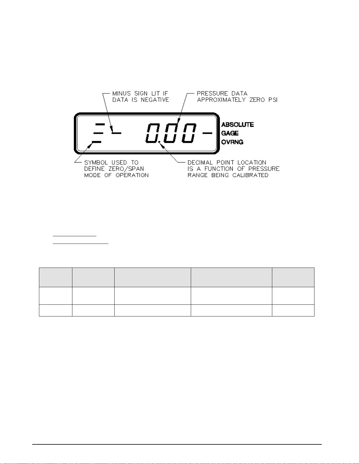
symbols as well as displaying the various data formats employed. For example, in Figure 3-2, the data format
shown is obtained as soon as the ZERO/SPAN position of the rotary switch has been selected.
Figure 3-1. Instrument Calibration Set-Up
NOTE: UPC5200 shown, Power (AC Input) and Input Port are on back side of UPC5210 Rack Mountable Calibrator.
Calibration
9
Page 13
10
3.3 Zero/Span Calibration
Selecting the ZERO/SPAN position on the Condec Calibration Module (PN 60109) places the instrument into its
ZERO/SPAN calibration mode. The display is shown in Figure 3-2.
NOTE: Absolute only unit requires vacuum pump with PSIA test standard to obtain readings below local barometric
pressure.
Figure 3-2. Zero/Span Calibration for Gage Only Units
Starting with the instrument's lowest pressure range, perform steps 1 and 2 shown in Table 3-1 for each pressure
range.
NOTE: Perform step 1 in all ranges prior to doing step 2.
Perform the following for each step:
1. Gage Only Units
Absolute Only Units:
: Adjust input pressure to the appropriate (either 0 or 100%) value.
Must use a vacuum pump with PSIA test standard, to reach as close to 0 PSIA as
possible (maximum .05 PSIA).
2. Perform the action indicated by Table 3-1 when pressure input readings are stable.
STEP NO. PRESSURE
INPUT VALUE
10%
(Note 3 below)
2 100%
NOTES:
1. If readings are not stable or are not within ± 20% of zero, the zero correction cannot be entered.
2. If readings are not stable or are not within ± 5% of 100%, the span correction cannot be entered.
3. Absolute only unit: Maximum PSIA test standard display reading of 0.05 PSIA.
OPERATOR ACTION
REQUIRED
ENTER
Press
Press
ENTER
Table 3-1. Zero and Span Calibration Sequence
button
button
RESULTING DISPLAY
INDICATION
0% Note 1 below
100% Note 2 below
REMARKS
3.4 Linearity and Hysteresis Calibration
Install the Condec Calibration Module, (PN 60109), and select the LYN/HYS position of the rotary switch on the
module. This places the UPC5200/UPC5210 into its linearization/hysteresis calibration mode. The display is
shown in Figure 3-3 below.
NOTE: The Zero/Span Calibration needs to be performed prior to Linearity and Hysteresis Calibration . For Absolute only
unit, vacuum pump with PSIA test standard must be used to obtain readings below local barometric pressure.
UPC5200/UPC5210 Operation and Maintenance Manual
Page 14
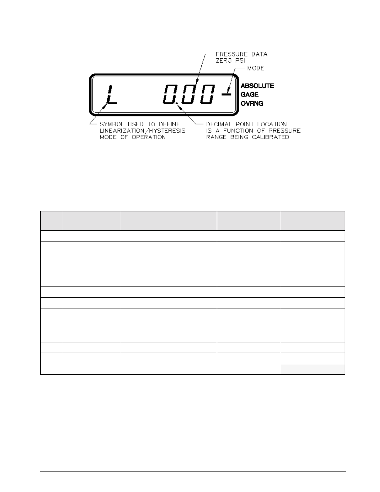
Figure 3-3. Linearity and Hysteresis Calibration
Starting with the instrument's lowest pressure range, sequentially perform the thirteen steps described in
Table 3-2, for each pressure range being calibrated. Perform the following for each step:
1. Adjust input pressure to the appropriate value without overshooting the setting. If value is overshot by
more than 1%, vent unit and repeat steps.
2. Perform the action as indicated when the readings are stable. Should not take longer than 15 minutes. If
it takes longer, check system for leaks. If no leaks are found, the CPU or transducer may be defective.
STEP
NO.
INPUT PRESSURE %
OF RANGE
10 (Note 4 below)
210
320
430
540
650
760
870
980
10 90
11 100 No Action Required H Note 3 below
12 50
13 0 (Note 4 below) No Action Required L
OPERATOR ACTION REQUIRED
Press
ZERO
Switch
ENTER
Press
ENTER
Press
ENTER
Press
ENTER
Press
ENTER
Press
ENTER
Press
ENTER button
Press
Press ENTER button
Press ENTER button
ENTER button
Press
button
button
button
button
button
button
STATUS SYMBOL IN
LEFT MOST DIGIT
L Zero on Display
L Notes 1 & 2 below
L Notes 1 & 2 below
L Notes 1 & 2 below
L Notes 1 & 2 below
L Notes 1 & 2 below
L Notes 1 & 2 below
L Notes 1 & 2 below
L Notes 1 & 2 below
L Notes 1 & 2 below
H Notes 1 & 2 below
REMARKS
Table 3-2. Linearization and Hysteresis Calibration Sequence
When step no. 11 is reached, the display changes so that the left most status symbol is
H
. This remains for step 12
and down to approximately 0.00 PSI.
NOTES:
1. If reading is in motion or correction required is not within ±0.8% of Full-Scale, no entry is made.
2. If entry is valid, the display momentarily indicates the correction value (in percent) and the memory location
at which it is stored.
3. If 100% ±0.05% is not obtained, repeat the Zero/Span calibration sequence.
4. Absolute only unit: Maximum PSIA test standard display reading of 0.05 PSIA.
Calibration
11
Page 15
3.5 Shunt Resistor Calibration
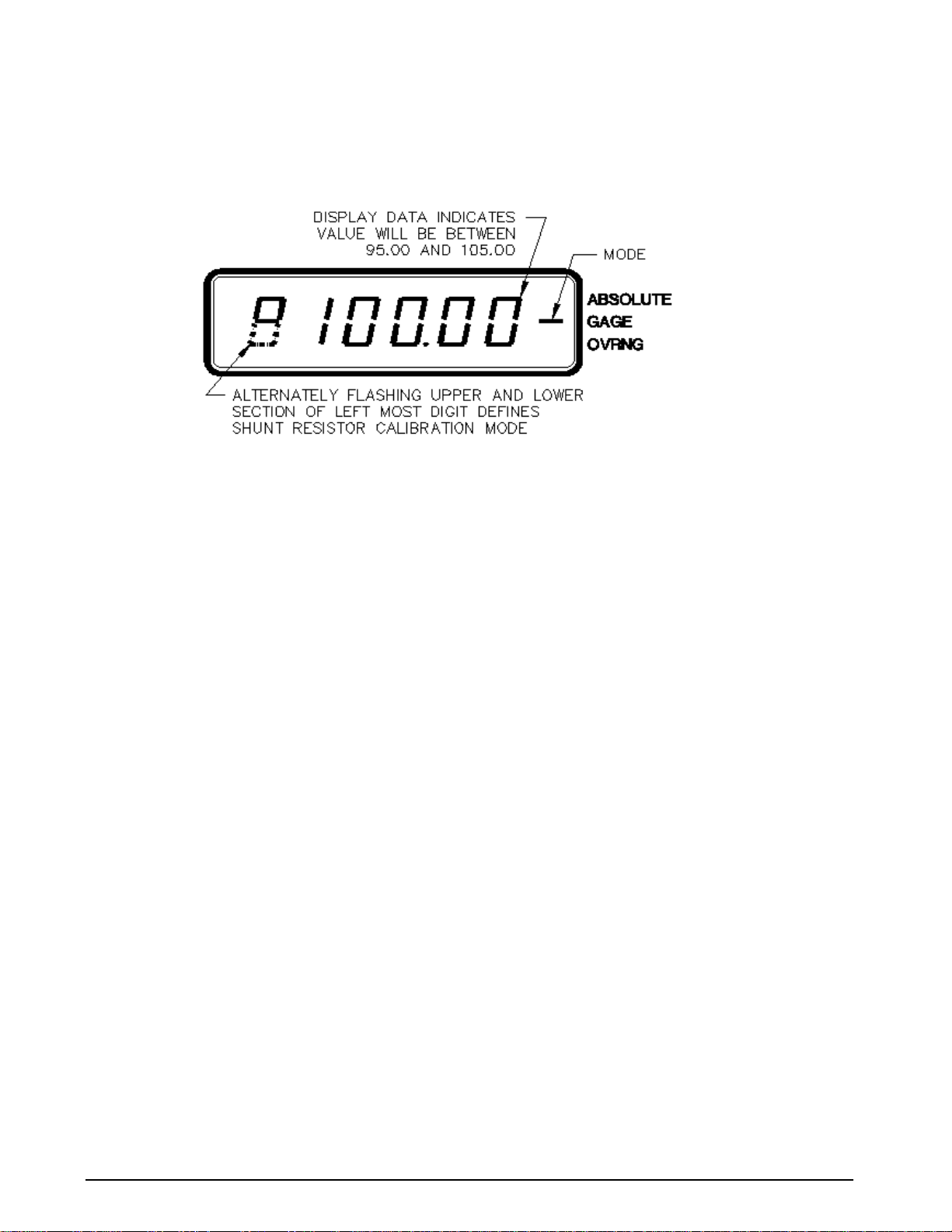
Install the Condec Calibration Module (PN 60109) and select the SHUNT position of the rotary switch on the
module. This places the UPC5200/UPC5210 into its SHUNT RESISTOR calibration mode. The display is
shown in Figure 3-4.
Figure 3-4. Shunt Resistor Calibration
With the UPC5200/UPC5210's highest pressure range selected, perform the four step sequence described below:
1. Gage Only Units: Be sure the input pressure to the UPC5200/UPC5210 is at 0 PSIG.
NOTE: Absolute Only Units: Must use a vacuum pump with PSIA test standard, to reach as close to 0 PSIA as
possible (maximum PSIA test standard display reading of 0.05 PSIA).
2. Press and hold the ZERO button on the Condec Calibration Module until a stable zero indication is
obtained.
3. Release the
(100 ± 5.00%)
4. Press the
display digits are momentarily illuminated.
ZERO button and allow the display to stabilize at its shunt resistor calibration number.
ENTER button on the Condec Calibration Module. When accepted, the bottom half of all
3.6 Current Input Calibration
To calibrate the current input, a current generator capable of generating 20 mA must be connected to the
COMMON and CURRENT INPUT jacks, see Figure 2.2 on page 4 (14). The DISPLAY SELECT switch (16)
should be on the CURRENT position.
1. Set the Condec Calibration Module (PN 60109) to the ZERO/SPAN position. The display is similar to
Figure 3-2 on page 10.
2. Press the
3. Set the Current Generator for 20 mA output. Press the
read
NOTE: If the display reading is off, set the Current Generator to 0, and press the ENTER button on the Condec
Calibration Module. Set the Current Generator for 20 mA output. The display reads 20.000. If the display
reading is off, press the
requires servicing.
ZERO button on the module. The display reads 0.00.
ENTER button on the module. The display should
20.00.
ENTER button on the module. If the display reading is not 20.000, CPU is faulty and
4. Disconnect the current generator.
3.7 Permanent Data Storage
After completing the above calibration procedures, the new data that has been entered into the computer must be
permanently stored. The sequence to do this is as follows:
1. Select the DATA RECALL position of the rotary switch on the Condec
2. Press the
STORE pushbutton on the module.
3. If the data is accepted, the four-digit number on the right side of the display indicates
STORE button is pressed.
the
Calibration Module, (PN 60109).
1 020 for as long as
12 UPC5200/UPC5210 Operation and Maintenance Manual
Page 16

3.8 Normal Mode Test
After completing the above calibration procedures, you must perform a normal mode test. A current generator
capable of generating 20 mA must be connected to the COMMON and CURRENT INPUT jacks, see Figure 2.2
on page 4 (14). The DISPLAY SELECT switch (16) should be on the CURRENT position.
1. Set the Condec Calibration Module to the NORMAL MODE position.
DISPLAY SELECT switch should be in the CURRENT position. The display reads 20.000.
2.
3.9 Self-Check Test
1. Remove the Condec Calibration Module.
2. Press the
100 to verify the unit's accuracy, then it returns to the normal mode automatically.
3. The pneumatic portion of the calibration is now complete. The pressure standard and the Condec
Calibration Module can now be disconnected.
ZERO pushbutton (12) on the UPC5200/UPC5210 until the unit sho ws CAL. The display sho ws
Calibration 13
Page 17
4.0 Maintenance & Service
This section outlines the mechanical and basic electrical repair procedures for the UPC5200/UPC5210.
4.1 Troubleshooting
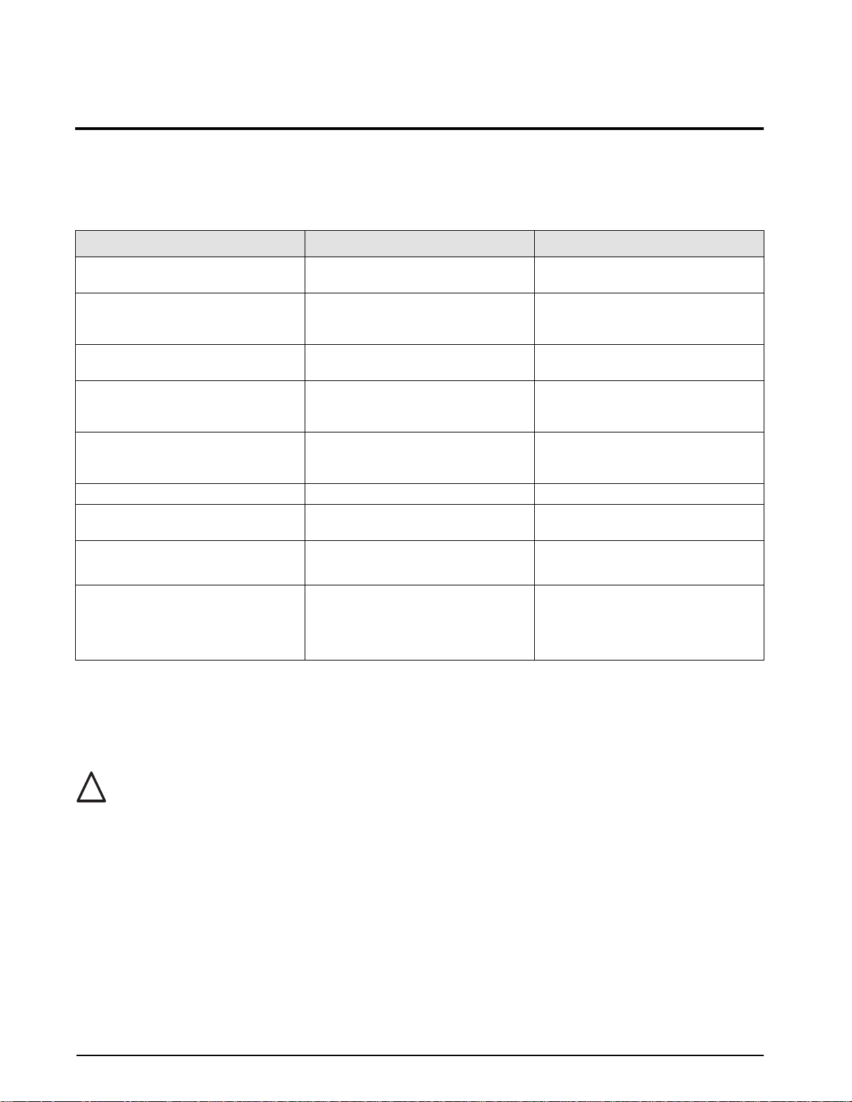
Use Table 4-1 below for information on troubleshooting the UPC5200/UPC5210.
Symptom Problem Remedy
Display does not light up. Unit will not energize. Check fuse, check power source, check
power switch.
Display slowly decreases over time. Leak in system. Check all compression and pipe fittings
with Snoop®, bottle of liquid leak gas
detector (PN 64781).
Display does not respond when Vernier
knob is turned.
Display increases or decreases when
COARSE (Pressure) or VENT valves are
closed.
Unit does not stay in CAL, display shows
"o", display reads a high value @ zero
PSIG.
Display does not show zero. Display will not zero. Perform a ZERO/SPAN calibration.
Display shifts, will not be steady. Transducer drifts or Possible over
Unit does not cycle when Pump Control
switch is on.
Unit cycles, but does not pressurize. Debris in check valve seat in intensifier,
No Vernier control. Readjust isolation valves on Orion;
replace O-ring on Vernier piston.
No Pressure or Vent control. Replace valve seats or O-rings in valves;
check valve needles.
Transducer over-pressurized. Replace transducer.
Replace transducer.
pressure.
Fuse blown on Pump Control Board.
No power.
deformity in seat.
Replace fuse.
Check that power is on.
Remove seats in intensifier and clean
and/or replace.
No supply pressure.
Check to see if there is sufficient supply
pressure.
Table 4-1. UPC5200/UPC5210 Troubleshooting
4.2 Maintenance & Service Procedures
The repair procedures cover the major components and sub-assemblies which are critical to the proper
functioning of the calibrators and that need periodic maintenance over the life of the unit.
Only those persons who are formally trained as skilled technicians should attempt to repair these units.
!
Caution
Although some mechanical sub-assemblies could be replaced without venting cylinder it is not
recommended. All safety precautions should be observed due to the presence of electrical and
high-pressure components. Unit must always be unplugged from power source.
14 UPC5200/UPC5210 Operation and Maintenance Manual
Page 18
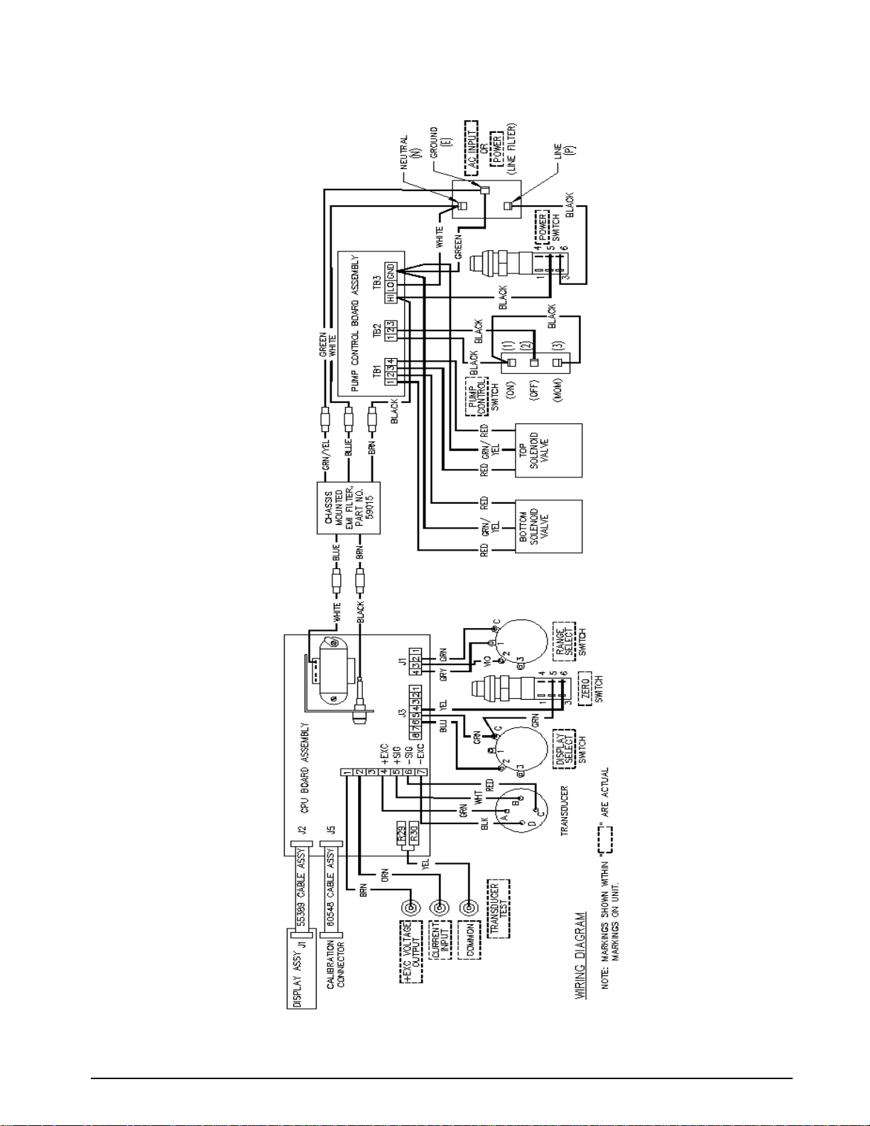
Figure 4-1. UPC5200/UPC5210 Wiring Diagram
Maintenance & Service 15
Page 19

4.2.1 Panel/Chassis Removal and Installation
UPC5200 Removal
Tools required: Phillips screwdriver
1. Loosen and remove the 10 screws (PN 14862) that secure the panel assembly to the enclosure.
2. Lift the panel and chassis by first grasping the regulator knob and test port and second, grasping under
the panel edges. Tilt the panel at an angle by lifting the right side before the left side as you face the
panel. Ensure that the wire harnesses do not catch and snag.
3. Gently set the panel/chassis assembly on a bench top. It can be rested on the panel bottom with the
accumulator supported by a screwdriver handle.
UPC5200 Installation
Tools required: Phillips screwdriver
1. Lift the panel and chassis by first grasping the regulator knob and test port.
2. Gently place panel/chassis assembly into enclosure. Tilt the panel at an angle by lifting the right side
before the left side as you face the panel. Ensure that the wire harnesses do not catch and snag.
3. Align mounting holes and install the 10 screws (PN 14862) that secure the panel assembly to the
enclosure.
UPC5210 Remo
Tools required: Phillips screwdriver
val
1. Loosen and remove the 14 screws (PN 14861) from top, bottom, and sides that secure the panel assembly
to the enclosure. Also, loosen and remove the three screws (P/N 14861) from the rear of unit that secure
the enclosure to the AC INPUT/INPUT PORT panel.
2. Lift the panel and chassis by grasping the handles located on the front of the rack mountable panel.
Ensure that the wire harnesses do not catch and snag.
3. Gently set the panel/chassis assembly on a bench top. It can be rested on the panel bottom with the
accumulator supported by a screwdriver handle.
UPC5210 Installation
Tools required: Phillips screwdriver
1. Lift the panel and chassis by grasping the handles located on the front of the rack mountable panel..
2. Gently place panel/chassis assembly into enclosure. Ensure that the wire harnesses do not catch and
snag.
3. Align mounting holes and install 14 screws (PN 14862) from top, bottom, and sides that secure the
panel/chassis assembly to the enclosure. Also, align mounting holes and install the three screws (P/N
14862) from the rear of unit that will secure the enclosure to the AC INPUT/INPUT PORT panel.
4.2.2 Accumulator, Intensifier & ORION-3A (PN 55287) Removal
Tools required: Phillips screwdriver
11/32" wrench or nutdriver
.061" hex wrench
adjusting screwdriver (small flat blade)
11/32" open end wrench (thin)
7/16" open end wrench
NOTE: See Table 4-2 on page 34 and Figure 4-2 on page 35 for additional ORION-3A parts information.
1. Vent the system to atmosphere before attempting to work on the unit. Disconnect the power cord from
the power source.
2. Remove front panel from its enclosure as described in Section 4.2.1 and carefully set on a bench top.
3. Using a 7/16" wrench, remove the following tubing sections:
•Accumulator to supply pressure gauge (1/8" dia.)
•Accumulator to pressure inlet on ORION-3A manifold (1/8" dia.)
•Accumulator to intensifier outlet (1/4" dia.)
16 UPC5200/UPC5210 Operation and Maintenance Manual
Page 20

4. Loosen and remove the six screws that secure the two clamps that hold the intensifier and accumulator.
5. Remove the accumulator by sliding out.
6. Loosen the fitting nut at the intensifier end of the long 1/4" diameter tubing section that connects the
solenoid valve to the intensifier. There is no need to remove the tubing.
7. Remove the two clamps and the intensifier.
8. Using a 7/16" wrench, remove the following tubing sections:
• Vent port to ORION-3A manifold vent outlet (1/8" dia.)
9. If the transducer is wired via a connector, remove the connector by turning counter-clockwise. If the
transducer is hard-wired, loosen and remove the four transducer wires (red, white, green, black) from the
terminal block, TB1, on the CPU board, using the small flat-blade screwdriver.
10. Break the wire ties that hold the transducer wires so that the wires are free.
11. Using the 11/32" thin wrench, loosen and carefully remove the transducer from the ORION-3A
manifold.
12. Remove the panel knobs from the Coarse (pressure), Vernier and Vent valves using the .061" hex wrench.
13. Loosen and remove the two panel scre ws (PN 60837) from the panel front that secure the manifold to the
panel.
14. Remove the five retaining nuts and lock washers that secure the chassis to the panel.
15. Lift the chassis enough to allow the ORION-3A manifold to clear and remove the manifold.
16. Reposition the chassis over the mounting studs and secure with at least two nuts.
4.2.3 ORION-3A Manifold, Valve Seat Removal
Tools required: A/R solvent (de-natured alcohol)
socket wrench
3/4" socket
needle housing socket (65580)
isolation valve needle housing socket (PN 68509)
hex wrench (.050")
hex wrench (.061")
needle-nose pliers
tube fluorinated krytox grease (PN 55593)
electric hand drill
No. 43 drill bit
No. 4-40 tap
tap handle
small hammer
NOTE: See Table 4-2 on page 34 and Figure 4-2 on page 35 for additional parts information.
1. Secure the manifold by its center portion, in a bench vise, with the valve knobs pointing upward.
2. Using the .061" hex wrench, loosen and remove the knob inserts (4) from the pressure and vent valve
stems.
3. Loosen the 3/4" locknuts (1) on the pressure and vent valve threaded needle housings (10).
4. Using the needle housing socket (65580) and torque wrench, loosen and remove the needle/housing
assembly (10, 1).
5. To disassemble the isolation valves (two inner valves), first remove the valve needle (18) by turning the
gear clockwise.
6. Loosen and remove the valve housings (19) using the isolation valve housing removal socket (59793)
female socket (65581) and torque wrench.
7. Remove the valve stem seats (8) and valve needle seats (9) using the needle-nose pliers.
8. Remove the inner and outer O-rings (28, 27) and back-up rings (31, 30) from the valve stem seats and
wash all parts in solvent (de-natured alcohol).
9. To remove valve seats (7) from either the COARSE (pressure), VENT or isolation valves, try blowing
compressed air through the inlet and outlet fittings. Otherwise, the center holes have to be drilled and a
tap used to extract the seat (Steps 10-13).
10. Using the electric hand drill with the No. 43 bit, carefully drill out the seat hole, ensuring that the drill
does not touch the hole in the manifold housing directly beneath the seat.
Maintenance & Service 17
Page 21

11. Blow out any chips from the seat area using compressed air.
12. While holding the 4-40 tap steady and perpendicular to the seat, slowly turn until the tap starts to engage
the seat.
13. When the tap has engaged into the seat, use a small hammer and gently knock upward against the tap
handle to extract the seat.
14. After the seat has been removed, blow any remaining chips from the seat area.
4.2.4 ORION-3A Manifold, Vernier Control Disassembly
Tools required: A/R solvent (de-natured alcohol)
1-1/4" open end wrench
screwdriver (flat-blade)
socket wrench
isolation valve needle housing socket (PN 68508)
isolation valve needle housing socket (PN 68509)
NOTE: See Table 4-2 on page 34 and Figure 4-2 on page 35 for additional parts information.
1. With the manifold housing mounted in a vise, turn the vernier shaft (14) clockwise until the piston is
bottomed.
2. Loosen and remove the end cap (13) using a 1-1/4" wrench. At certain points during removal the end cap
might appear to lock up. If this occurs, rotate the shaft clockwise until the end cap is free to turn.
3. Remove the O-ring (29) from the end cap.
4. Remove the self-sealing screw (36) that acts as the piston key.
5. Extract the piston (15) by partially screwing in the threaded end of the shaft and pulling.
6. Remove the O-ring (32) from the piston groove.
7. To disassemble the end cap/shaft assembly, mount the end cap in the vise.
8. Loosen and remove the locknut (20) using the isolation valve needle housing socket (PN
68509), and
socket wrench.
9. Loosen and remove the end bushing (12) using the isolation valve housing socket (PN 68508) and socket
wrench. Remove the shaft (14). Remove the ball bearings (41) from both sides of the shaft flange.
10. Use a small pick or screwdriver to remove the O-ring (27) from the inner groove of the end cap (13).
Also, remove backup retainer (39) from inner groove of the end cap (13).
11. Wash all parts in solvent and blow dry with compressed air.
4.2.5 ORION-3A Manifold, Vernier Control Reassembly
Tools required: tube fluorinated Krytox grease (PN 55593)
1-1/4" wrench
screwdriver (flat-blade)
socket wrench
isolation valve needle housing socket (PN 68508)
isolation valve needle housing socket (PN 68509)
torque wrench
NOTE: See Table 4-2 on page 34 and Figure 4-2 on page 35 for additional parts information.
1. Coat all new O-rings with fluorinated Krytox grease before installing.
2. Install the small O-ring (27) into the end cap inner groove. Also, install backup retainer (39) in inner
groove of the end cap (13).
3. Hold shaft (14) vertically with end that goes through end bushing (12) tow ard ceiling. Place light coating
of grease on threads of shaft. Place thick coating of grease on top of shaft bearing surface.
4. Allowing grease to hold ball bearings in place, slide end bushing (12) over top of shaft and down to
contact top of ball bearings.
5. Rotate shaft assembly 180˚, placing end bushing towards the floor. Be careful not to displace ball
bearings. Place thick coating of grease on shaft and bearing surface. Place sixteen chrome ball bearings
(41) on greased surface, allowing grease to hold them in place.
6. Install shaft (14) with bearings (41) into end cap.
18 UPC5200/UPC5210 Operation and Maintenance Manual
Page 22

7. Install the end bushing (12) and tighten until snug using the isolation valve needle housing socket (PN
68508) and socket wrench.
8. Tighten so that shaft rotates, but should be firm. Feel vertical motion of shaft (14). If motion exists,
retighten end bushing.
9. Install the locknut (20) into end cap (13) and using the isolation valve needle housing socket (PN 68509)
and torque wrench. Torque to approximately 325 in/lbs. (may not get to torque on all sub-assemblies).
10. Install the O-ring (32) in the piston groove and install the piston (15) into the VERNIER cavity. Ensure
that the piston keyway is facing the hole into which the self-sealing screw (36) is assembled.
11. Install the self-sealing screw (36) and tighten until snug.
12. Apply a thin coat of fluorinated Krytox grease and install the O-ring (29) and backup washer (38) on the
end cap/shaft assembly, install into manifold and tighten until snug.
4.2.6 ORION-3A Manifold, Valve Seat Installation
Tools required: needle-nose pliers
tube fluorinated Krytox grease (PN 55593)
No. 43 drill
A/R solvent (de-natured alcohol)
hex wrench (.050")
hex wrench (.061")
torque wrench
socket wrench
3/4" socket
needle housing socket (PN 65580)
isolation valve needle housing socket (PN 68509)
female socket (PN 65581)
NOTE: See Table 4-2 on page 34 and Figure 4-2 on page 35 for additional parts information.
1. Install a new seat (7) by placing it into the seat well with the needle-nose pliers. Ensure that the seat is
centered within the cavity and gently tap it with a blunt end of a drill bit to install.
2. Install the valve needle seat (9) with the smaller diameter end facing outward.
3. Install new O-rings (28, 27) inside and outside of the valv e stem seat. Coat all O-rings and back-up rings
(30, 31) with fluorinated Krytox grease before installation. Make sure that the rings are installed in the
proper order.
4. Install the valve stem seat (8) by grasping the small diameter end with the needle-nose pliers and
positioning in the valve cavity, then gently pushing with the blunt end of a drill bit.
5. For COARSE (pressure) and VENT valves (two outer valves), disassemble the valve needle (11) from its
housing (10) and check for any burrs or dirt on the threads which might interfere with smooth operation.
6. Clean both the needle (11) and housing (10) in solvent, dry the parts and apply a small amount of
fluorinated Krytox grease to the needle threads before reassembly.
7. Assemble the Valve Needle (11) into the valve needle housing (10) and turn it until it stops.
8. Reinstall the needle/housing assembly into the valve cavity until finger tight.
9. Mount the manifold body (16) in a vise. For the COARSE (pressure) and VENT valves only, torque the
needle/housing assembly to 325 in-lb. using the needle housing socket (PN 65580) and
torque wrench.
10. Install the housing lock nuts (1) onto the housing (10) and tighten until snug with the 3/4" socket.
11. Using the .050" hex wrench, install and tighten the lock nut (2) and set screw (34).
12. Install the knob insert (4) over the valve needle (11) shaft, align the set screws (23) with the indents and
tighten with the .061" hex wrench.
13. For the isolation valves (two inner valves), install the needle housing (19) and tighten until snug using
the isolation valve needle housing installation socket (PN 68509) and torque wrench.
NOTE: There is no specified torque, so use care when tightening so as not to break the socket nibs.
14. Install the gear (6) over the isolation valve needle (18) shaft, align the set screws (26) with the indents
and tighten with the .061" hex wrench.
15. Apply a small amount of fluorinated Krytox grease to the threads of the isolation valve needles (18) and
install into the valve by turning counter-clockwise. Rotate the gear until the needle just stops at the seat.
Maintenance & Service 19
Page 23

4.2.7 Accumulator, Intensifier and ORION-3A Manifold, Panel Installation
NOTE: See Figure 2-1 on page 5, for the items listed in parenthesis.
Tools required: 7/16" open end wrench
Phillips screwdriver
hex wrench (.061")
Snoop®, liquid leak gas detector (PN 64781)
11/32" open end wrench (thin)
1. If not already done, remove the panel knobs from the COARSE (pressure), VERNIER and VENT valves
using the .061" hex wrench.
2. With the panel facing down against the bench, if not already done, remove the five retaining nuts and
lock washers that secure the chassis to the panel. Lift up the chassis enough so that the ORION-3A
manifold is able to clear.
3. Install the manifold with the transducer port side facing the panel bottom. Install the two mounting
screws (PN 60837) from the panel front and tighten until snug.
4. Secure the chassis to the panel with the five nuts and lock washers (tighten until snug).
5. Install the VERNIER knob (17) onto the VERNIER valve shaft (14). Align the set screws (25) with the
indentations on the vernier valve shaft and tighten until snug using the .061" hex wrench.
NOTE: To install the COARSE (pressure) and VENT Valve Knobs, and perform a valve adjustment, follow the
procedure in Section 4.2.8 after completing the following steps.
6. Install the transducer into the manifold port, tighten with the 11/32" thin wrench and reconnect its wire
connector.
NOTE: If transducer is hard-wired, connect the four wires to the Terminal block, TB1, on the CPU board per the
following:
(+ Excitation) TB1-4 Green wire (- Signal) TB1-6 Red wire
(+ Signal) TB1-5 White wire (- Excitation) TB1-7 Black wire
7. Using a 7/16" wrench, install the following tubing section that goes from vent port to ORION-3A
manifold vent outlet (1/8" dia.)
8. Replace the intensifier and the two clamps.
9. Realign and tighten the fitting nut at the intensifier end of the long 1/4" diameter tubing section that
connects the solenoid valve to the intensifier.
10. Replace the accumulator by sliding in thru the clamps.
11. Thread and tighten the six screws that secure the two clamps that hold the intensifier and accumulator.
12. Using a 7/16" wrench, realign and tighten the following tubing sections:
• accumulator to intensifier outlet (1/4" dia.)
• accumulator to pressure inlet on ORION-3A manifold (1/8" dia.)
• accumulator to supply pressure gauge (1/8" dia.)
13. Using a pressure source connected to the input port (4) set input pressure to 100 PSI. Enable the
CONTROL switch (20) and monitor the pressure as it builds in the ACCUMULATOR gauge (9). Turn the
PUMP CONTROL switch (20) off when 1,000 PSI has been achie v ed. Check all fittings for leaks. If there
PUMP
are no leaks vent system and remove pressure source.
NOTE: See Section 2.2 on page 4 for pressure source connection procedure.
14. Install panel/chassis assembly in its enclosure as described in Section 4.2.1 on page 16.
4.2.8 ORION-3A Manifold, Valve Adjustment Procedure
Tools required: hex wrench (.050")
hex wrench (.061")
NOTE: See Table 4-2 on page 34 and Figure 4-2 on page 35 for additional parts information (* denotes reference to
Figure 2-1 on page 5).
1. If not already done, remove the ORION-3A COARSE and VENT valve knobs (3) using the .061" hex
wrench.
20 UPC5200/UPC5210 Operation and Maintenance Manual
Page 24

2. Energize the unit and let warm up. Turn RANGE SELECT switch to highest range. To adjust the
COARSE valve, go to step 3.
3. Using a .050" hex wrench, loosen the set screw (34) on the locknut (2) and turn the locknut clockwise to
its stop.
4. Check to see that the knob insert (4) is securely fastened to the valve shaft (11). If it is loose, re-tighten
the set screws (23) with the .061" hex wrench.
5. Close the COARSE valve by turning the knob insert (4) clockwise until you feel the valve needle seat on
the O-ring (valve is now in closed position).
6. Rotate gears on both ISOLATION valves (two inner valves), counter-clockwise until they stop, then
rotate clockwise 1/2 turn (opening isolation valves).
7. With a pressure source connected to the INPUT PORT (*4). Use the REGULATOR (*1), to increase the
regulated pressure (monitor REGULATED PRESSURE gauge) to 1/10 of Full Scale. Enable the
CONTROL switch (20) and monitor the pressure as it builds in the ACCUMULATOR gauge (*9). Turn
PUMP
the PUMP CONTROL switch (20) off when 80% to 100% of Full Scale has been achieved.
8. Open the VENT valve (*8) to atmosphere, then close the VENT valve (*8).
9. Slowly open the COARSE valve by turning the knob insert (4) counter-clockwise until you notice the
displayed pressure increase. Then turn the knob insert slightly clockwise until the pressure stops rising.
10. Mark a radial line at the 12 o'clock position on the knob insert.
11. Turn the knob insert (4) clockwise to move the mark to the 6 o'clock position.
12. Turn the locknut (2) counter-clockwise until it contacts the bottom of the stop washer. Tighten the set
screw (34) on the locknut with the .050" hex wrench.
13. Install the COARSE valve knob (3) on the knob insert (4) and engage its gear (5) with the smaller
ISOLATION valve gear (6). Turn the knob clockwise until the ISOLATION valve is slightly snug.
CAUTION: Do not use excessive torque when tightening coarse valve knob. Doing so may damage seat.
14. Remove the COARSE valve knob. Align the set screws (25) with the indentations on the knob insert .
Install the knob on the knob insert while engaging the knob gear (5) with the ISOLATION valv e gear (6).
15. Tighten the set screws (25) with the .061" hex wrench. The COARSE valve is now adjusted.
16. To adjust the VENT valve, follow steps 3 and 4.
17. Close the COARSE valve by turning the COARSE knob (*2) clockwise.
18. Close the VENT valve knob insert (4) clockwise until slightly snug.
19. With a pressure source connected to the INPUT PORT (*4). Use the REGULATOR (*1), to increase the
regulated pressure to 1/10 of full scale. Enable the
PUMP CONTROL switch (20) and monitor the
pressure as it builds in the ACCUMULATOR gauge (*9). Turn the PUMP CONTROL switch (20) off
when 80% to 100% of Full Scale has been achieved. Open the COARSE valve until the indicated
pressure stabilizes and then close the COARSE valve.
20. Slowly turn the VENT valve knob insert (4) counter-clockwise until the display starts to decrease, then
turn the knob insert (4) slightly until the indicated pressure stops decreasing.
21. Follow steps 10 through 15 replacing the term "COARSE valve" with "VENT valve". The VENT valve
is now adjusted.
4.2.9 Accumulator Assembly, O-ring (PN 58051) Replacement, Filter (PN 56993) Cleaning
Tools required: Phillips screwdriver
5/8" open end wrench
adjustable wrench
A/R 1/4" wide teflon tape, (PN's 60575)
tube fluorinated Krytox grease (PN 55593)
A/R solvent (de-natured alcohol)
Disassembly:
1. Remove accumulator assembly from UPC5200/UPC5210 per Section 4.2.2 on page 16.
2. Place accumulator body in vise, using flats.
3. Remove plug adapter fitting (PN 57134) using adjustable wrench.
Maintenance & Service 21
Page 25

4. Remove O-ring (PN 58051) and back-up ring (PN 59735).
5. Remove accumulator body from vise and place adapter fitting in vise, using flats, threads facing
upwards.
6. Remove filter retainer fitting (PN 57811) using wrench.
7. Remove plug adapter fitting from vise, turn up side down, and remove filter.
8. Clean the filter (PN 56993) in solvent (de-natured alcohol) and blow-dry with compressed air.
Assembly:
1. Place filter (PN 56993) into filter retainer fitting (PN 57811).
2. Finger tighten filter retainer fitting into plug adapter fitting (PN 57134).
3. Place plug adapter fitting (PN 57134) in a vise and tighten filter retainer fitting.
4. Grease O-ring/back-up ring groove on plug adapter fitting.
5. Grease both sides of O-ring (PN 58051) and back-up ring (PN 59735). Then install backup ring onto
plug adapter fitting, followed by O-ring.
NOTE: Use pointed bent pick when installing O-ring to Prevent damage. Verify Backup ring split is properly
aligned.
6. Place accumulator body in vise using flats. Grease accumulator body in O-ring seat area, then slowly
thread plug adapter fitting using an adjustable wrench into accumulator body.
NOTE: To help seat back-up ring hand tighten plug adapter fitting close to bottoming, then wrap an 8" piece of
22 AWG, solid buss wire around the edge of back-up ring within gap between accumulator body and plug
adapter fitting. Pull buss wire ends to squeeze back-up ring into proper position within accumulator body.
Verify backup ring split is properly aligned.
7. Tighten plug adapter fitting.
8. Install accumulator assembly into UPC5200/UPC5210 per Section 4.2.7 on page 20.
4.2.10 Intensifier Assembly, O-rings/Seals Replacement
NOTE: See Table 4-2 on page 34 and Figure 4-2 on page 35 for additional parts information.
Tools required: Phillips screwdriver
5/8" open end wrench
1/4” hex key
3/16” hex key
3/8” hex key
adjustable wrench
check valve seat tool (PN 70711)
fitting holder tool (PN 70710)
tapered packing retainer tool (PN 70712)
check valve fitting tool (PN 70709)
A/R 1/4" wide teflon tape, (PN's 60575)
tube fluorinated Krytox grease (PN 55593)
Oil lubricant, (PN 60944)
A/R solvent (de-natured alcohol)
Disassembly Rings and Seals:
1. Remove intensifier assembly from UPC5200/UPC5210 per Section 4.2.2 on page 16.
2. Remove the 10 cap screws (1) and washers (2) from the end cap which has the single elbow fitting (23).
3. Remove the end cap (3) and O-ring (4).
4. Remove the piston (18).
5. Remove the small piston retainer (24) and 3 piston rings (22).
6. Remove the large piston O-ring (21) and 2 packings (20).
Disassembly of Check Valves:
1. Remove inlet check valve fitting (12) and outlet (16) ports.
2. For the outlet valve, remove, in order, the spring housing (8), spring (9), poppet (10) and seat (11).
3. For the inlet valve remove, in order, the seat (15), poppet (10) and spring (9).
22 UPC5200/UPC5210 Operation and Maintenance Manual
Page 26

Reassembly of Check Valves:
NOTES:
• Clean all parts with solvent and use shop air hose to remove any dust particles from all mechanical parts, except
screws and washers. Wipe the bores of the intensifier housing with a clean cloth before installing the piston. Replace
all damaged parts with new ones.
• For ease of assembly and to prevent damage to parts it is recommended to use the following tools during assembly:
• check valve seat tool (PN 70711)
• fitting holder tool (PN 70710)
• tapered packing retainer tool (PN 70712),
• check valve fitting tool (PN 70709)
For the outlet valve:
1. Assemble spring (9) and check valve (10) into spring housing (8).
1.1. Press check valve seat (11) into spring housing (8), using large diameter end of check valve seat tool
(PN 70711). Be sure check valve seat (11) is seated. Coat grease in bottom groove marks, in hole of
end cap (19) where fitting item (16) goes.
NOTE: The larger of the 2 seats belongs to the outlet check valve. Very important not to get grease in
counter-sunk hole located at center of groove marks.
1.2. Place grease on bottom of items (11/8) sub-assembly.
NOTE: Very important not to get grease on item 10.
1.3. Slide (11/8) sub-assembly into end cap (19), until properly seated on bottom. Thread high pressure
tube fitting (16) into end cap (19) and tighten using a 5/8” wrench.
2. For the inlet valve, perform the following steps:
2.1. Thread AN side of inlet check valve fitting (12) into fitting holder tool (PN 70710).
2.2. Place a small amount of grease (PN 55593) on inlet check valve fitting (12) between groove area and
top of fitting to enable ease of installation of packing retainer (13).
2.3. Place tapered Packing Retainer Tool (PN 70712), stepped part, into hole in packing retainer (13).
Place Grease on sides of tool.
2.4. Slide packing retainer (13) onto packing retainer tool (PN 70712) and down into groove of inlet
check valve fitting (12).
2.5. Remove packing retainer tool (PN 70712) and wipe the grease from tool.
2.6. Grease both sides of O-ring (14) and install into groove on inlet check valve fitting (12).
2.7. Use stepped part of packing retainer tool (PN 70712) on check valve seat (15) to install into recessed
end of inlet check valve fitting (12). Check valve seat (15) must seat flat. If needed, tap tool very
lightly to seat, but make sure no damage occurs to inlet check valve fitting (12).
2.8. Tap round dowel (25) into hole on threaded shaft of piston ring retainer (24). Leave extra material
protruding from both sides of shaft. Trim round dowel (25), using cutters, to top of threads on both
sides. Thread piston ring retainer (24) into piston (18), two or three turns, to form threads on round
dowel (25). Remove piston ring retainer (24) from piston (18).
2.9. Grease inside wall of end cap (19) where inlet check valve fitting (12), sub-assembly, O-ring &
backup ring will touch.
2.10. Place spring (9) and check valve (10) into end cap (19).
2.11. Thread “AN” side of inlet check valve fitting (12), sub-assembly into Fitting Holder Tool (PN
70710). Now place sub-assembly into Check Valve Fitting Tool (PN 70709), such that, flat side of
item (15) goes through beveled side of tool.
2.12. Slide item (12) back and forth in tool a few time to align O-ring and backup ring. Remove
sub-assembly from check valve fitting tool (PN 70709) and unthread from fitting holder tool (PN
70710). Thread item (12) sub-assembly into end cap (19), where spring (9) and check valve (10)
were previously installed. Tighten using a 5/8” wrench.
Maintenance & Service 23
Page 27

Reassembly of Rings and Seals:
NOTE: Clean all parts with solvent and use shop air hose to remove any dust particles from all mechanical
parts, except screws and washers. Wipe the bores of the intensifier housing with a clean cloth before installing
the piston. Replace all damaged parts with new ones.
1. Smear a medium amount of grease in O-ring cavity on piston (18). Grease both sides of the two backup
rings (20) and O-ring (21). Install into groove on piston (18).
NOTE: Split of each backup ring, item 84, must be 180o from each other and ends overlapping properly.
2. Lightly coat edges of backup rings (20) and O-ring (21) with oil lubricant (PN 60944).
3. Lightly coat both inside diameters of housing (17).
4. Place grease on piston ring retainer (24) where piston rings (22) seat.
5. Place grease on both sides of the three piston rings (22) and install the three piston rings (beveled sides
aligned) onto piston ring retainer (24).
6. Slide piston (18) into housing (17), being careful not to damage wall areas. Slide until smaller diameter
of piston (18) is exposed from side of housing (17).
7. Thread item (24), with the three piston rings (22) into piston (18) approximately four turns.
8. Stand housing (17) on end, with piston ring retainer (24) facing upward. Push piston ring retainer (24) to
verify it will go into housing (17) fully. Top of piston ring retainer (24) must be slightly below surface of
housing (17).
9. Place housing (17) on its side. Place 3/16" hex key in item (24) and 1/4" hex key in piston (18). Rotate
1/4" hex key to tighten.
10. Remove the 3/16" hex key and verify piston (18) will rotate. If piston rotates remove 1/4" hex key. If it
doesn’t rotate, loosen piston slightly.
11. Grease both sides of O-ring (4), and end cap (3) O-ring groove. Then install O-ring (4) into groove of
end cap (3).
12. Place housing (17) sub-assembly with large I.D. upward and install end cap (3) into housing (17).
13. Place cap screw (1) through washer (2) and thread finger tight into end cap (3). Repeat for the other nine
cap screws.
14. Use torque wrench and 1/4" hex key socket to torque each bolt to 325 in/lbs.
NOTE: Torque cap screws in a side to side pattern, (do not use a circular pattern), and in small increments to
insure end cap, item 67 is seated flat to Housing surface.
15. If previously removed, place 1/4" Teflon tape, two turns, on 90o NPT elbow (23). Thread and tighten 90
NPT elbow (23) into end cap (3). Align so that 90o NPT elbow (23) is parallel with the small hole located
on the side of housing (17).
16. Grease both sides of O-ring (7) and O-ring seat area on end cap (19). Install O-ring (7) onto end cap (19)
and in turn place onto housing (17). Orient such that the small hole located on housing side is on your
left at the "9 o’clock" position. The inlet check valve fitting (12) placement hole located on end cap (19)
must be at the 6 o’clock position.
17. Place Cap Screw (5), thru Washer (6), end cap (19) and thread finger tight into housing (17). Repeat for
the other nine cap screws. Use torque wrench and 3/8” hex key socket to torque each bolt to 325 in/lbs.
NOTE: Torque cap screws in a side to side pattern (do not use a circular pattern) and in small increments to
ensure end cap (item 83) is seated flat to housing surface.
18. Install intensifier assembly into UPC5200/UPC5210 per Section 4.2.7 on page 20.
o
24 UPC5200/UPC5210 Operation and Maintenance Manual
Page 28

4.2.11 Regulator (Standard Pneumatic) and Solenoid Removal
Solenoid 120 VAC input - PN 56851, Solenoid 220 VAC input - PN 54366
Tools required: Phillips screwdriver
7/16" open end wrench
9/16" open end wrench
A/R 1/4" wide teflon tape, (PN's 60575)
A/R 1/2" wide teflon tape, (PN's 60911)
1/2" socket
socket wrench
1/4" hex wrench
NOTE: See Figure 4-4 on page 37.
1. Vent any remaining gas from the system to atmosphere. Disconnect the power cord from the power
source.
2. Remove front panel from its enclosure as described in Section 4.2.1 on page 16, and carefully place on a
bench top.
3. Remove regulator knob cap and two screws that secure the round plate.
4. Loosen and remove the locknut using a 1/2" socket while holding the knob. Remove the knob by turning
counter-clockwise.
5. (UPC5210 Only) Loosen tube nut on INPUT PORT fitting. Remove the two screws and
POWER/INPUT PORT panel.
6. Remove all tubing sections that connect to the regulator/solenoid assembly.
7. Loosen the mounting collar in the panel rear using a 1/4" hex wrench.
8. Remove the regulator/solenoid assembly by sliding out from the panel rear.
9. Mount the regulator in a bench vise by the flats in the base.
10. Note the orientation of the solenoids, as well as the inlet and outlet fittings in the regulator. Remove the
fittings and any remnants of teflon tape from the pipe threads.
4.2.12 Regulator (Standard Pneumatic) and Solenoid Installation
Solenoid 120 VAC input - PN 56851, Solenoid 220 VAC input - PN 54366
Tools required: Phillips screwdriver
7/16" open end wrench
9/16 " open end wrench
A/R 1/4" wide teflon tape, (PN's 60575)
A/R 1/2" wide teflon tape, (PN's 60911)
snoop, liquid leak gas detector (PN 64781)
1/2" socket
socket wrench
1. Wrap two layers of teflon tape on the pipe threads of each fitting and install into the inlet and outlet of the
regulator and ensure that each, as well as, solenoids are oriented properly. Use a bench vise when doing
this.
2. Insert the new regulator/solenoid assembly into the panel through hole. Pass the adjusting end through
the mounting ring. Do not tighten cap screw until adjusting knob is installed.
3. Install the tubing sections to the inlet and outlet fittings.
(UPC5210 only) Replace the POWER/INPUT PORT panel and 2 mounting screws. Thread and tighten
tube nut on INPUT PORT fitting.
4. Install the adjusting knob on the threaded shaft by turning clockwise. Turn adjusting knob on threaded
shaft until bottomed and install locking nut and tighten. T urn knob until it bottoms. Position the regulator
so that the bottom of the knob is 1/2" from the panel surface, then tighten the cap screw on the
mounting collar.
5. Using a pressure source connected to the input port (4) set regulated pressure to 100 PSI. Enable the
PUMP CONTROL switch (20) and monitor the pressure as it builds in the ACCUMULATOR gauge (9).
Turn the
PUMP CONTROL switch (20) off when 1,000 PSI has been achieved. Check all fittings for
leaks. If there are no leaks vent system and remove pressure source.
6. Install panel/chassis assembly in its enclosure as described in Section 4.2.1 on page 16.
Maintenance & Service 25
Page 29

4.2.13 Regulator (Tescom) and Solenoid Removal
Solenoid 120 VAC input - PN 56851, Solenoid 220 VAC input - PN 54366
Tools required: Phillips screwdriver
7/16" open end wrench
9/16" open end wrench
A/R 1/4" wide teflon tape, (PN's 60575)
A/R 1/2" wide teflon tape, (PN's 60911)
1/2" socket
socket wrench
1/4" hex wrench
flat blade screwdriver (small)
channel locks
NOTE: See Figure 4-4 on page 37.
1. Vent any remaining gas from the system to atmosphere. Disconnect the power cord from the power
source. .
2. Remove front panel from its enclosure as described in Section 4.2.1 on page 16, and carefully place on a
bench top.
3. Remove regulator knob cap by prying off with small screwdriver.
4. Loosen and remove the locknut using a 1/2" socket while holding the knob. Remove the knob by turning
counter-clockwise.
(UPC5210 only) Loosen tube nut on INPUT PORT fitting. Remove the 2 screws and POWER/INPUT
PORT panel.
5. Remove all tubing sections that connect to the regulator inlet and outlet fittings.
6. Loosen and remove the panel mounting nut using channel locks.
7. Remove the regulator/solenoid assembly by sliding out from the panel rear.
8. Mount the regulator in a bench vise by the flats in the base.
9. Note the orientation of the solenoids, as well as the inlet and outlet fittings in the regulator. Remove the
fittings and any remnants of teflon tape from the pipe threads.
4.2.14 Regulator (Tescom) and Solenoid Installation
Solenoid 120 VAC input - PN 56851, Solenoid 220 VAC input - PN 54366
Tools required: Phillips screwdriver
7/16" open end wrench
9/16" open end wrench
1/2" socket
socket wrench
torque wrench
A/R 1/4" wide teflon tape, (PN's 60575)
A/R 1/2" wide teflon tape, (PN's 60911)
snoop, liquid leak gas detector (PN 64781)
NOTE: See Table 4-4 on page 37. Call Condec for replacement part numbers.
1. Wrap two layers of teflon tape on the pipe threads of each fitting and install into the inlet and outlet of the
regulator and ensure that each is oriented properly. Use a bench vise when doing this.
2. Insert the new regulator/solenoid assembly into the panel through hole. Thread the large mounting nut
onto the body from the panel front.
3. Install the tubing sections to the inlet and outlet fittings.
(UPC5210 only) Replace the POWER/INPUT PORT panel and two mounting screws. Thread and
tighten tube nut on INPUT PORT fitting.
4. Install the REGULATOR knob on the threaded shaft by turning clockwise, until it sits just low enough to
allow locknut to be placed on threaded shaft. Hold knob in position and install the locknut.
5. Close REGULATOR, by turning regulator knob counter-clockwise.
6. Using a pressure source connected to the INPUT PORT (4) set regulated pressure to 100 PSI. Enable the
PUMP CONTROL switch (20) and monitor the pressure as it builds in the ACCUMULATOR gauge (9).
26 UPC5200/UPC5210 Operation and Maintenance Manual
Page 30

Turn the PUMP CONTROL switch (20) off when 1,000 PSI has been achieved. Check all fittings for
leaks. If there are no leaks vent system and remove pressure source.
7. Install panel/chassis assembly in its enclosure as described in Section 4.2.1 on page 16.
8. Energize the unit and let warm up. Turn range select switch to highest range.
9. Close the COARSE valve by turning the COARSE knob clockwise.
10. Using a pressure source connected to the INPUT PORT (4), turn the REGULATOR knob clockwise until
reaching between .5% to 1% of full scale, but not enough to disturb pressure relief valve.
NOTE: If pressure cannot be attained loosen locknut on shaft, rotate knob a few turns counter-clockwise, and
retighten locknut. If you hear the pressure relief valve open, rotate regulator knob counter-clockwise until relief
valve shuts off.
11. Remove locknut from threaded shaft, and rotate knob counter-clockwise until bottoming out on large
locknut. After touching large locknut rotate knob clockwise 1/8 turn. Hold knob in position, install and
tighten the locknut with 40 - 50 in-lbs. of torque using a 1/2" socket.
12. Open REGULATOR completely, by turning REGULATOR knob clockwise. If you reach between
10-11% of full scale and pressure relief valve was not disturbed regulator has been adjusted properly.
13. Replace regulator knob cap.
4.2.15 Panel Gauge Removal and Installation
•Regulated pressure gauge (PN 59745), 0–600 PSIG
•Regulated pressure gauge (PN 59751), 0–1,500 PSIG
•Accumulator gauge (PN 59749), 0–6,000 PSIG
•Accumulator gauge (PN 59696), 0–15,000 PSIG
Tools required: Phillips screwdriver
7/16" wrench
9/16 " wrench
A/R 1/4" wide teflon tape (PN 60575)
snoop, liquid leak gas detector (PN 64781)
Panel Gauge Removal
1. Vent any remaining gas from the system to atmosphere. Disconnect the power cord from the power
source.
2. Remove front panel from its enclosure as described in Section 4.2.1 on page 16, and carefully place on a
bench top.
3. Disconnect the tubing section that connects to the gauge fitting.
4. Loosen the two thumb-nuts that hold the gauge mounting U-clamp.
5. While gripping the square portion of the gauge port with the 9/16" wrench, remove the tube connector
fitting from the gauge.
6. Remove the two thumb-nuts, the mounting U-clamp, and the gauge.
Panel Gauge Installation
Tools required: Phillips screwdriver
7/16" wrench
9/16" wrench
A/R 1/4" wide teflon tape (PN 60575)
snoop, liquid leak gas detector (PN 64781)
1. Before installing a new gauge, wrap two layers of new teflon tape on the port.
2. Install gauge into panel, secure with U-clamp and tighten the two thumb screws.
3. While gripping the square portion of the gauge port with the 9/16" wrench, tighten the Female Tube
Connector onto the gauge.
4. Attach the tubing section that connects to the gauge fitting.
5. Using a pressure source connected to the INPUT PORT (4) set regulated pressure to 100 PSI. Enable the
PUMP CONTROL switch (20) and monitor the pressure as it builds in the ACCUMULATOR gauge (9).
Turn the
PUMP CONTROL switch (20) off when 1,000 PSI has been achieved. Check all fittings for
leaks. If there are no leaks vent system and remove pressure source.
6. Install panel/chassis assembly in its enclosure as described in Section 4.2.1 on page 16.
Maintenance & Service 27
Page 31

4.2.16 Test Port Quick-Connect Fitting (PN 59004) and Filter (PN 54188), Removal and Installation
Every two months, a coating of flourinated Krytox grease should be applied to the inner seal of the test port
fitting. The pressure cap (PN 58216) should be plugged in whenever the unit is not in use.
NOTE: For simplest method, apply fluorinated krytox grease to the outside surface between sealing lip and end of
mating pressure cap. Do not put grease on flat end of tip, as this may allow grease to enter system. Vent unit line
pressure to atmosphere. Plug pressure cap into test port. Rotate pressure cap clockwise and counter-clockwise to
transfer fluorinated krytox grease to O-ring seal.
If there is leakage out of the port when the pressure cap is in place, replace the port fitting.
Tools required: Phillips screwdriver
11/16" open end wrench
adjustable wrench
9/16" open end wrench
A/R solvent (de-natured alcohol)
A/R 1/4" wide Teflon tape (PN 60575)
A/R 1/2" wide Teflon tape (PN 60911)
tube fluorinated grease (PN 55593)
snoop, liquid leak gas detector (PN 64781)
1. Vent any remaining gas from the system to atmosphere. Disconnect the power cord from the power
source.
2. Remove front panel from its enclosure as described in Section 4.2.1 on page 16, and carefully set on a
bench top.
3. Loosen and remove the tubing end nut from the reducing tube fitting (PN 59830).
NOTE: Use PN 54047 for reducing tube fitting field replacement.
4. Loosen and remove the reducing tube fitting and filter (PN 54188) from the test port quick-connect
fitting.
5. Clean the filter (PN 54188) in solvent (de-natured alcohol) and blow-dry with compressed air.
6. Grasp the test port quick-connect fitting on the flats from the rear of panel with a 11/16" wrench and
using an adjustable wrench, turn the locknut counter-clockwise. Remove locknut.
7. Remove old and install new test port quick-connect fitting (PN 59004) through front of panel.
8. Thread and tighten locknut by grasping the test port quick-connect fitting on the flats from the rear of
panel with a 11/16" wrench and using an adjustable wrench, turn the locknut clockwise.
9. Slide filter (PN 59764) into reducing tube fitting and install into the test port quick-connect fitting.
10. Replace and tighten the tubing end nut on the reducing tube fitting.
11. Using a pressure source connected to the INPUT PORT (4) set regulated pressure to 100 PSI. Enable the
PUMP CONTROL switch (20) and monitor the pressure as it builds in the ACCUMULATOR gauge (9).
Turn the
PUMP CONTROL switch (20) off when 1000 PSI has been achieved. Check all fittings for
leaks. If there are no leaks vent system and remove pressure source.
12. Install panel/chassis assembly in its enclosure as described in Section 4.2.1 on page 16.
4.2.17 Test Port (output) Hose Quick-Connect Fitting and Filter (PN 56991), Removal and Installation
Tools required: 5/8" open end wrench
3/4" open end wrench
13/16" open end wrench
A/R solvent (de-natured alcohol)
tube fluorinated grease (PN 55593)
Removal:
1. Loosen and unthread quick-connect fitting assembly from test port hose using 3/4" and 5/8" wrenches.
2. Remove cheat seal pad (PN 54854) from AN thread side of adapter fitting (PN 60803)
3. Place quick-connect fitting assembly in a vise using filter fitting (PN 59588) as clamping area.
4. Loosen and unthread quick-connect fitting (PN 59034) using 13/16" wrench.
5. Remove filter fitting (PN 59588) from vise.
6. While holding filter fitting (PN 59588) vertically, remove filter (PN 56991) and then O-ring (PN 55608)
from filter fitting.
7. Inspect and clean parts in solvent (de-natured alcohol) and blow-dry with compressed air. Replace worn
or damaged parts with new ones.
28 UPC5200/UPC5210 Operation and Maintenance Manual
Page 32

Installation:
1. Grease inside cavity on bottom flat (none allowed in hole) of quick-connect fitting (PN 59034).
2. Grease O-ring seat groove area in filter fitting (PN 59588).
3. Grease both sides of O-ring (PN 55608). While holding filter fitting (PN 59588) vertically, place O-ring
(PN 55608) and then filter (PN 56991) into filter fitting (PN 59588).
4. Thread quick-connect fitting (PN 59034) onto filter fitting (PN 59588).
5. Place filter fitting (PN 59588) in a vise and tighten quick-connect fitting (PN 59034) using 13/16"
wrench.
6. Remove from vise.
7. Place a cheat seal pad, cheat seal pad (PN 54854) on AN part of assembly and thread into test port
(output) hose. Tighten assembly using 5/8" and 3/4" wrenches.
4.2.18 Input Port Filter (PN 54188), Removal and Installation
The port filter is a sintered element filter, which is easily removed for inspection and cleaning.
Tools required: Phillips screwdriver
7/16" open end wrench
9/16" open end wrench
A/R solvent (de-natured alcohol)
snoop, of liquid leak gas detector (PN 64781)
Input Port Filter Removal
1. Vent any remaining gas from the system to atmosphere. Disconnect the power cord from the power
source.
2. Remove front panel from its enclosure as described in Section 4.2.1 on page 16, and carefully place on a
bench top.
3. Loosen and remove the tubing end nut from the tube union (PN 59886).
4. Loosen and remove the tubing end nut from the input port bulkhead AN fitting (PN 59707).
5. Remove the the tube union (PN 59886), port connector (PN 59746) and filter from the bulkhead AN
fitting (PN 59707).
NOTE: Use PN 55705 for port connector field replacement.
6. Clean the filter (PN 54188) in solvent (de-natured alcohol) and blow-dry with compressed air.
Input Port Filter Installation
1. To reinstall, reverse the order of steps 3, 4 and 5 of the "Input Port Filter Removal" procedure above.
2. Using a pressure source connected to the INPUT PORT (4) set regulated pressure to 100 PSI. Enable the
PUMP CONTROL switch (20) and monitor the pressure as it builds in the ACCUMULATOR gauge (9).
Turn the
PUMP CONTROL switch (20) off when 1,000 PSI has been achieved. Check all fittings for
leaks. If there are no leaks vent system and remove pressure source.
3. Install panel/chassis assembly in its enclosure as described in Section 4.2.1 on page 16.
4.2.19 Input Port Hose Quick-Disconnect Female Fitting, Removal and Installation
Tools required: 3/4" open end wrench
9/16" open end wrench
A/R solvent (de-natured alcohol)
A/R 1/2" wide Teflon tape (PN 60911)
Removal:
1. Loosen and unthread
quick-disconnect fitting from input hose using 3/4" and 9/16” wrenches.
2. Remove cheat seal pad (PN 54854) from “AN” thread side of adapter fitting (PN 60803) and place
CGA-580 nipple (PN 57150) pressure fitting in vise, holding by flats located on nipple.
3. Loosen and unthread adapter fitting (PN 60803) from CGA-580 nipple (PN 57150) pressure fitting using
a 3/4" wrench.
4. Remove CGA-580 nut (PN 57154) by sliding over threads of CGA-580 nipple (PN 57150) pressure
fitting.
5. Remove remnants of teflon tape from fittings.
Maintenance & Service 29
Page 33

6. Inspect and clean parts in solvent (de-natured alcohol) and blow-dry with compressed air. Replace worn
or damaged parts with new ones.
Installation:
1. Wrap two turns of 1/2" Teflon Tape around threads of CGA-580 Nipple (PN 57150) pressure fitting.
2. Hold CGA-580 nipple (PN 57150) pressure fitting in vise by flats located on nipple.
3. Slide CGA-580 nut (PN 57154) over threads of CGA-580 nipple (PN 57150) pressure fitting.
4. Thread and tighten adapter fitting (PN 60803) onto CGA-580 nipple (PN 57150) pressure fitting using a
3/4" wrench.
5. Remove assembly from vise and install a cheat seal pad (PN 54854) on AN thread side of adapter fitting
(PN 60803).
6. Thread into input hose and tighten using 3/4" and 9/16" wrenches.
4.2.20 AC Fuse (PN 57472), Removal and Installation
1. Disconnect the power cord from the power source and line filter. Remove the Fuse holder at POWER.
2. Inspect fuse, if blown replace with 1/2 Amp 250 Volt, 20mm x 5mm diameter ( PN 57472).
3. Replace the Fuse holder at POWER location.
4.2.21 Panel Mounted AC Power/EMI Line Filter (PN 58870), Removal and Installation
Tools required: Phillips screwdriver
1/4" open end wrench or nutdriver
A/R soldering iron
A/R shrink sleeving (PN 60735)
A/R heat gun
1. Disconnect the power cord from the power source and line filter. Remove front panel from its enclosure
as described in Section 4.2.1 on page 16, and carefully set on a bench top.
2. Remove the 3 cable connectors from the line filter terminals.
NOTE: Some units may not have connectors and will have to have wire leads unsoldered.
3. Loosen and remove the line filter retaining nuts on the rear of panel.
NOTE: Some units may have screws on the front panel.
4. Remove the AC line filter.
5. To install a new line filter, reverse the order of steps 1 through 4. Connect (or solder) wires to the new
line filter as follows:
Green wire to terminal (E) Ground
White wire to terminal (N) Neutral
Black wire to terminal (P) Line
4.2.22 Chassis Mounted EMI Line Filter (PN 59015), Removal and Installation
Tools required: Phillips screwdriver
1/4" open end wrench or nutdriver
A/R soldering iron
A/R shrink sleeving (PN 60735)
A/R heat gun
1. Disconnect the power cord from the power source and line filter. Remove front panel from its enclosure
as described in Section 4.2.1 on page 16, and carefully set on a bench top.
2. Remove the five cable connectors from the line filter terminals.
3. Loosen and remove the line filter retaining nuts on the side of chassis.
4. Remove the line filter.
5. To install a new line filter, reverse the order of steps 1 through 4.
Connect wires to the two wire side of new line filter as follows:
Blue wire to CPU White wire
Brown wire to CPU Black wire
30 UPC5200/UPC5210 Operation and Maintenance Manual
Page 34

Connect wires to the three wire side of new line filter as follows:
Green/Yellow wire to AC INPUT Green wire from terminal (E) Ground
Blue wire to AC INPUT White wire from terminal (N) Neutral
Brown wire to pump control board, black wire from TB3 terminal HI
NOTE: Some units may have POWER marking in place of AC INPUT on panel.
4.2.23 Pump Control Switch (PN 60307), Removal and Installation
Tools required: Phillips screwdriver
Flat screwdriver
1/4" open end wrench or nutdriver
A/R soldering iron
A/R shrink sleeving (PN 60735)
A/R heat gun
Removal:
1. Disconnect the power cord from the power source and line filter. Remove front panel from its enclosure
as described in Section 4.2.1 on page 16, and carefully set on a bench top.
2. Remove the two black wires from pump control board TB2 terminals 1 and 2.
3. Loosen and remove the nut on the panel front and remove the switch from the panel rear..
4. Unsolder and remove the three wires from the switch terminals.
Installation:
1. Use shrink sleeving over wires/terminals for protection. Connect and solder the harness wires to the new
switch terminals per the following:
erminal Function
T
Rear of Switch 1 On
2 Off
3 Momentary
Black wire to switch terminal 1
Black wire to switch terminal 2
Black jumper wire between switch terminals 1 & 3
2. Install the new switch through the rear of panel. Rotate switch so that the momentary position is toward
bottom of panel and secure it from the front of panel with the mounting nut.
3. Replace the two black wires to the pump control board TB2. Connect terminal 1 of switch to terminal 1
of TB2, and terminal 2 of switch to terminal 2 of TB2.
4. Install panel/chassis assembly in its enclosure as described in Section 4.2.1 on page 16.
4.2.24 Power Switch (PN 58878), Removal and Installation
Tools required: Phillips screwdriver
11/16" open end wrench
A/R soldering iron
A/R shrink sleeving (PN 64567)
A/R heat gun
Removal:
1. Disconnect the power cord from the power source and line filter. Remove front panel from its enclosure
as described in Section 4.2.1 on page 16, and carefully set on a bench top.
2. Loosen the switch mounting nut and lock washer from the rear of panel.
3. Loosen and remove the trim ring from the panel front.
4. Remove switch, lock washer and nut from rear of panel as one item.
5. Unsolder and remove the wires from the switch terminals.
Installation:
1. Slide shrink sleeving over wires, connect and solder the wires onto their respective switch terminals:
Maintenance & Service 31
Page 35

Terminal Color
Normally open Black
(C) common Black
2. Pull shrink sleeving over switch and connections. Apply heat. Install the new switch, lock washer and nut
through the panel rear as one item. Hand tighten the trim ring from front of panel.
3. Tighten the switch mounting nut and lock washer from the rear of panel.
CAUTION: If wrench is used, do not over tighten, damage may occur to switch.
4. Install panel/chassis assembly in its enclosure as described in Section 4.2.1 on page 16.
4.2.25 Range Select Switch (PN 55924) and Display Select Switch (PN 55933), Removal and Installation
Tools required: Phillips screwdriver
9/16" open end wrench or nutdriver
A/R soldering iron
061" hex wrench
Removal:
1. Disconnect the power cord from the power source and line filter. Remove front panel from its enclosure
as described in Section 4.2.1 on page 16, and carefully set on a bench top.
2. Remove the switch knob using a .061" hex wrench.
3. Loosen and remove the mounting nut from the panel front.
NOTE: Intensifier and Accumulator will need to be removed prior to switch removal.
4. Unsolder and remove the wires from the switch terminals.
Installation:
1. Connect and solder the wires onto their respective switch terminals:
Range Select: T
1 Grey
(C) common Green
erminal Color
2 Violet
Display Select: Terminal Color
2 Blue
(C) common Green
(C) common Green
2. Install the switch through the panel rear, align with front panel markings, and secure with its mounting
nut.
3. Install the switch knob using a .061" hex wrench.
4. Replace tubing and components as necessary.
5. Install panel/chassis assembly in its enclosure as described in Section 4.2.1 on page 16.
4.2.26 Zero Switch (PN 58886), Removal and Installation
Tools required: Phillips screwdriver
11/16" open end wrench
A/R soldering iron
Removal:
1. Disconnect the power cord from the power source and line filter. Remove front panel from its enclosure
as described in Section 4.2.1 on page 16, and carefully set on a bench top.
2. Loosen the switch mounting nut and lock washer from the rear of panel.
3. Loosen and remove the trim ring from the panel front.
4. Remove switch, lock washer and nut from rear of panel.
5. Unsolder and remove the wires from the switch terminals.
32 UPC5200/UPC5210 Operation and Maintenance Manual
Page 36

Installation:
1. Connect and solder the wires onto their respective switch terminals:
Zero: T
Normally open Yellow
(C) common Green
erminal Color
2. Install the new switch, lock washer and nut through the panel rear. Hand tighten the trim ring from front
of panel.
3. Tighten the switch mounting nut and lock washer from the rear of panel. Replace CPU if necessary.
CAUTION: If wrench is used, do not over tighten, damage may occur to switch.
4. Install panel/chassis assembly in its enclosure as described in Section 4.2.1 on page 16.
4.2.27 CPU Assembly, Removal and Installation
120 VAC input - PN 54254, 220 VAC input - PN 54268
Tools required: Phillips screwdriver
Flat blade screwdriver (small)
11/32" open end wrench or nutdriver
Removal of CPU Board:
1. Disconnect the power cord from the power source and line filter. Remove front panel from its enclosure
as described in Section 4.2.1 on page 16, and carefully set on a bench top.
2. Disconnect and/or unsolder the wire connections attached to the CPU board assembly.
NOTE: It may be helpful to mark ends of wire with location. Also refer to the wiring diagram
Figure 4-1 on page 15.
3. Loosen and remove the five screws and two cable clamps (PN 59480) that hold the CPU board assembly
and remove the board.
Installation of Power Supply Board:
1. Position the new board over the five standoffs and install five screws and two cable clamps. Tighten the
screws until snug.
2. Connect and/or solder the wire connections attached to the CPU board assembly.
NOTE: Refer to the wiring diagram Figure 4-1 on page 15.
3. Install panel/chassis assembly in its enclosure as described in Section 4.2.1 on page 16.
4.2.28 Pump Control Board Assembly, Removal and Installation
120 VAC input - PN 56679, 220 VAC input - PN 56682
Tools required: Phillips screwdriver
Flat blade screwdriver (small)
11/32" open end wrench or nutdriver
Removal of Pump Control Board:
1. Disconnect the power cord from the power source and line filter. Remove front panel from its enclosure
as described in Section 4.2.1 on page 16, and carefully set on a bench top.
2. Disconnect the wires from the terminal blocks located on the pump control board assembly.
NOTE: It may be helpful to mark ends of wire with location. Also refer to the wiring diagram
Figure 4-1 on page 15.
3. Loosen and remove the four nuts that hold the pump control board and remove the board.
Installation of Power Supply Board:
1. Position the new board over the four standoffs and install four nuts. Tighten the nuts until snug.
2. Connect the wires to the terminal blocks located on the pump control board assembly (see Figure 4-1 on
page 15.
3. Install panel/chassis assembly in its enclosure as described in Section 4.2.1 on page 16.
Maintenance & Service 33
Page 37

4.3 ORION-3A Valve Assembly (55287) Parts List
The following table lists the component parts of the ORION-3A.
Ref Number PN Description Quantity
1 57482 Nut, valve needle housing 2
2 54401 Locknut 2
3 58079 Knob 2
4 57889 Knob, insert 2
5 57256 Gear, spur 40 teeth 2
6 59233 Gear, spur 18-tooth 2
7 55896 Valve Seat 4
8 59387 Valve Seat, stem 4
9 59045 Valve, needle seat 4
10 54540 Housing, valve needle 2
11 59551 Valve Needle 2
12 57600 Bushing, end 1
13 58554 Cap, end 1
14 58699 Shaft 1
15 58597 Piston 1
16 59309 Body, dual valve 1
17 57580 Knob 1
18 55533 Valve Needle 2
19 55159 Housing, valve needle 2
20 56784 Locknut,9/16-18UNF-3A, SST 1
21 58464 Setscrew,12-24NCx1/4 SST 14
22 58308 Ball, Tungsten Carbide 14
23 59383 Setscrew, 6-32NCx1/8 SST 4
24 58342 Screw, cap hex socket head, #2-56UNC-3A 6
25 59322 Setscrew, 6-32NCx1/4 SST 6
26 59326 Setscrew, 2-56NCx1/8, alloy steel 4
27 55569 O-ring, Fluorocarbon (Viton) color black w/white dot 5
28 55552 O-ring, Fluorocarbon (Viton) color black w/white dot 4
29 58090 O-ring, Fluorocarbon (Viton) color black w/white dot 1
30 60633 Retainer, Packing Backup 4
31 55570 Washer, backing 4
32 58045 O-ring, Fluorocarbon (Viton) color black w/white dot 1
33 59245 Washer, nylon 2
34 60202 Setscrew, hex 2
35 60837 Screw, MACH #10- 32NF SST 2
36 54905 Screw, self sealing 1
38 57027 Washer, backup 1
39 54448 Retainer, packing backup 1
40 55615 O-ring, Fluorocarbon (Viton) color black w/white dot 1
41 58314 Ball, chrome, steel 32
42 59731 Male connector, 1/8 tube x 1/8 NPT, stainless steel 3
Table 4-2. ORION-3A Valve Assembly Parts List
34 UPC5200/UPC5210 Operation and Maintenance Manual
Page 38
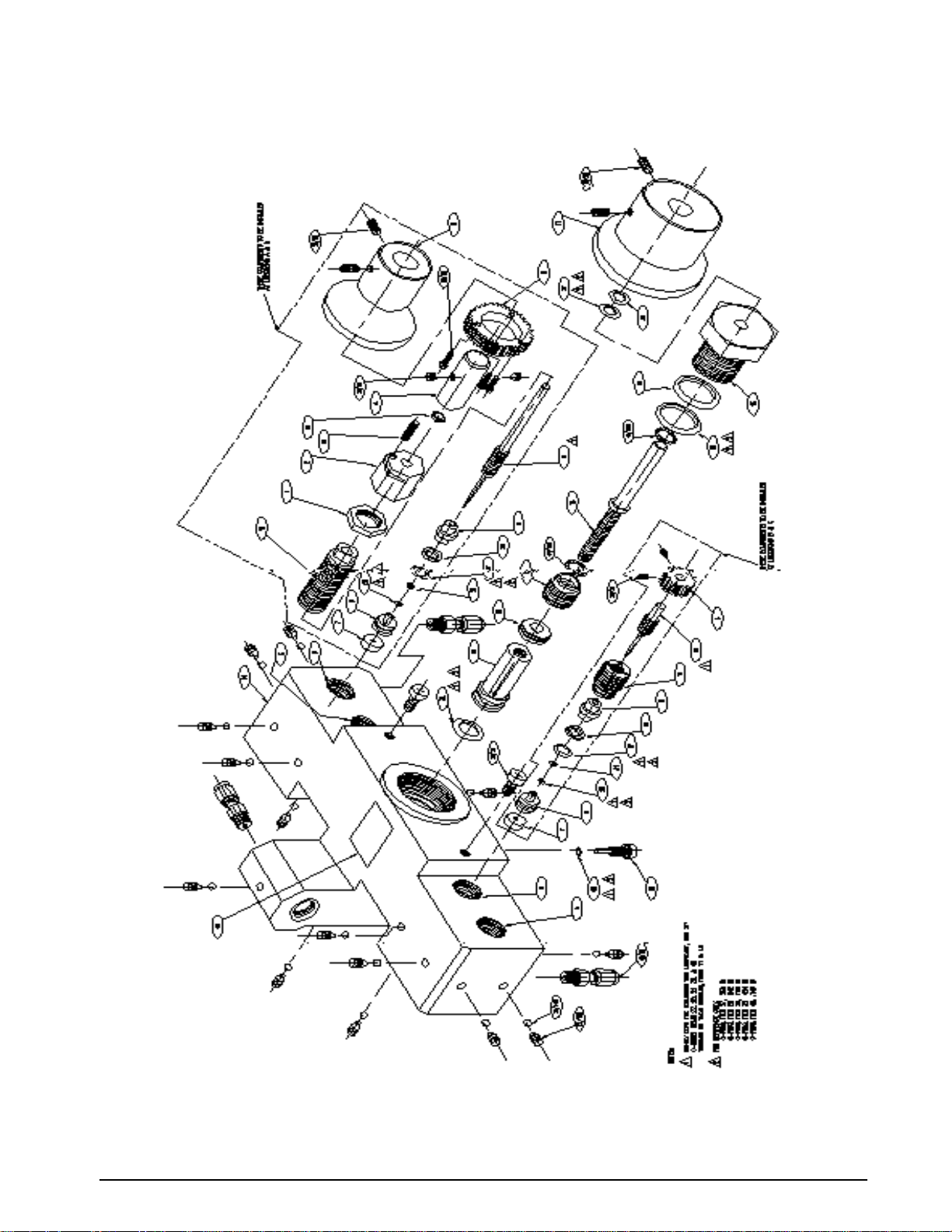
Figure 4-2. ORION-3A Part No. 55287 Exploded View
Maintenance & Service 35
Page 39

4.4 Intensifier Assembly Parts List
Ref
Number
1 59328 Screw, cap, socket 10
2 60704 Washer, flat 10
3 59548 Cap, end 1
4 55589 O-ring, Buna-N (Nitrile) 70 Durometer color black 1
5 59333 Screw, cap, socket head 10
6 59508 Washer, flat 10
7 55579 O-ring, Flourocarbon (Viton) 90 Durometer color black w/white dot 1
8 60133 Housing, spring 1
9 60343 Spring 2
10 57410 Check valve 2
11 56714 Seat, check valve 1
12 57236 Fitting, check valve inlet 1
13 54456 Retainer, packing backup 1
14 55596 O-ring, Flourocarbon (Viton) 90 Durometer color black w/white dot 1
15 57114 Seat, check valve 1
16 59785 Adapter, High Pressure 1/4 NPT Male to Swagelok 1
17 60333 Housing, piston 1
18 59070 Piston 1
19 58786 Cap, end 1
20 60579 Retainer, packing 2
21 55600 O-ring, Buna-N (Nitrile) 70 Durometer color black 1
22 54614 Ring, piston 3
23 59794 Elbow, 90 Tube to Male NPT 1
24 58752 Retainer, piston ring 1
25 69435 Dowel, round 1
PN Description Quantity
Table 4-3. Intensifier Parts List
36 UPC5200/UPC5210 Operation and Maintenance Manual
Page 40
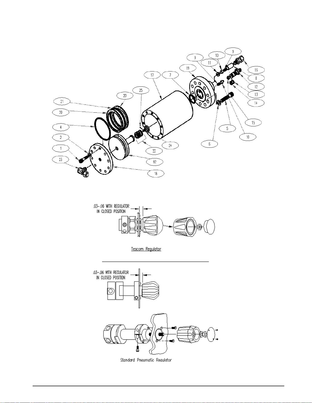
Figure 4-3. Intensifier Exploded View
Figure 4-4. Tescom and Standard Pneumatic Regulator Mounting
Maintenance & Service 37
Page 41
38
NOTES:
1- FOR SCHEMATIC SEE DWG. (D)KHP7316.
2-
OBSERVE POLARITY OF ICs, CAPACITORS, DIODES, AND TRANSISTORS.
3- TEST PROCEDURE: (A)KUA7317
4- MARK APPLICABLE DASH NUMBER, REVISION LEVEL, AND
DATE IN 1/8 INCH HIGH CHARACTERS. USE BLACK EPOXY INK.
5- ITEM 30 REFERENCE DESIGNATIONS: R16, R26, R41, R42,
R44, R46, R47, R54, WITH R28 IN KEU8924-1
& KEU8924-3 ONLY.
6- TRANSFORMER SHIELD TO BE INSTALLED AFTER TEST.
(REFERENCE PART NUMBER MB80-1)
7- ITEM 3 REFERENCE DESIGNATIONS: U1, U2, U3, U26, WITH
U23 IN KEU8924-1 & KEU8924-3 ONLY
8- ITEM 56 REFERENCE DESIGNATIONS: C8, C10-C20, WITH
C28 IN KEU8924-1 & KEU8924-3 ONLY
9- ITEM 65 REFERENCE DESIGNATIONS: CR4, CR5, CR7-CR9,
AND CR12, WITH CR10 IN KEU8924-1 & KEU8924-3 ONLY
10- TB1 IS MADE UP OF ONE (1) ITEM 82 AND ONE (1) ITEM 91,
TB2 IS MADE UP OF ONE (1) ITEM 82.
11- FOR 220VAC: REMOVE JUMPERS ON TRANSFORMER, ITEM 69,
12- REFERENCE:
BETWEEN PINS 1 & 3 AND 2 & 4.
ADD JUMPER BETWEEN PINS 2 & 3.
RE-MARK PART NUMBER AS APPLICABLE.
120VAC
KEU8924-1
KEU8924-2
KEU8924-3
220VAC
KEU8924-4
KEU8924-5
KEU8924-6
USED IN
UPC5000, UPC5200
UPS3000
UPC5100
13- ON KEU8924-2, ADD JUMPER TO E11 AND E12.
14- ON KEU8924-1 & -3:
15- ON KEU8924-3 ONLY, ADD JUMPER BETWEEN E3 AND TP7.
CUT CLAD AT CUT MARKS "G" & "E" AND BETWEEN R23A
MOUNTING HOLES.
USE TWO 8" LENGTHS OF ITEM 109, #22AWG BLK.INS.WIRE,
16-
TO CONNECT COMMON CLAD AS SHOWN IN HIDDEN LINES,
COMPONENT SIDE VIEW, SHEET 2.
17- ITEM 22 REFERENCE DESIGNATIONS: K5, WITH K4 USED IN
KEU8924-1 AND KEU8924-3 ONLY.
18- ITEM 32 REFERENCE DESIGNATIONS:
AND KEU8924-3, WITH R23, R23B USED IN KEU8924-3 ONLY.
19- ITEM 33 REFERENCE DESIGNATIONS: R55, WITH R11 IN
KEU8924-1 & KEU8924-2 ONLY
20- ITEM 35 REFERENCE DESIGNATIONS: R15, WITH R3 & R4
IN KEU8924-1 & KEU8924-2 ONLY
21- ITEM 37 REFERENCE DESIGNATIONS: R8, R9, R10, R18,
WITH R32 IN KEU8924-3 ONLY
22- ITEM 39 REFERENCE DESIGNATIONS: R59, WITH R58 USED
IN KEU8924-1 ONLY.
23- ITEM 53 REFERENCE DESIGNATIONS: C3, C29, WITH C9
KEU8924-1 AND KEU8924-3 ONLY.
24- ITEM 64 REFERENCE DESIGNATIONS: CR2, WITH CR1 USED
IN KEU8924-1 & KEU8924-2 ONLY
25- ITEM 66 REFERENCE DESIGNATIONS: CR6, WITH CR11 USED
IN KEU8924-1 & KEU8924-3 ONLY. EATON P/N KGF327A
MAY BE USED AS A SUBSTITUTE.
26- ITEM 83 REFERENCE DESIGNATIONS:
ITEM 84 REFERENCE DESIGNATIONS:
27 CUT ITEM 101 TO REQUIRED LENGTHS. ON CIRCUIT SIDE OF
BOARD ASSEMBLY JUMPER U8 PINS 9 AND 10 TO U8-7(GND).
DELETE J2 PINS 6 THRU 10,
DELETE J2 PINS 16 THRU 20, &
CUT CLAD GOING TO PINS 1 & 14
JUMPER PINS J2-1 & J2-2
R30 USED IN KEU8924-1
XU4, XU6, XU7, XU8, XU13.
XS1, XU5, XU14, XU15.
28- KEU8924-1 (54254) & KEU8924-3 (54263) ONLY: ON CIRCUIT
SIDE OF BOARD, CUT CLAD BETWEEN CR12 ANODE AND VIA
UNDER U10. CUT CLAD BETWEEN CR10 ANODE AND U6-4.
ADD 3 1/2" 30 AWG WIRE, ITEM 101, BETWEEN CR10 ANODE
AND VIA UNDER U10. SEE PICTORIAL.
29- KEU8924-1 ONLY: INSTALL ITEM 11 AND ITEM 31 IN SERIES AT
R33 LOCATION. TWIST, DO NOT SOLDER, LEADS TOGETHER.
LEAVE APPROXIMATELY 1/4" LEAD LENGTH ON EACH RESISTER.
NOTE TO CONDEC MANUFACTURING:
ITEMS 11 & 31 REQUIRED FOR UPC5200 &UPC5210 UNITS. REMOVE
ITEM 11 AND SOLDER ITEM 31 ONLY PRIOR TO INSTALLING INTO
UPC5000 OR UPC5010.
CPU ASSEMBLY
-1----
---111
---A/R A/R A/R
---333
---1--
---1" 60628
---222
---333
---111
---111
---111
---111
---111
---111
---111
---111
---222
---444
---555
---222
---3-3
---3-3
---111
---111
---111
---111
---111
---111
---111
---111
222---
CPU ASSEMBLY
113
---1--
CPU ASSEMBLY
112
111 WIRE, 22AWG, WHITE---6"6"6"
4 1/2"4 1/2"
101
30 AWG WIRE-WRAP
LOCK WASHER, INTERNAL TOOTH
TEST POINT KFU307A
SOCKET, IC
SOCKET, IC
SOCKET, IC
SOCKET, IC
SOCKET, IC
SOCKET, IC
SOCKET, IC
CONNECTOR
CONNECTOR
CONNECTOR
CONNECTOR
CONNECTOR
CONNECTOR
---111
---212
---767
---122
---1--
---2--
---1- 1
---222
---333
-6 -5 -4 -3 -2
QTY REQD FOR DASH NO.
111---
131213---
222--- C6,C7CM05ED200J03CAPACITOR, MICA55
-1
63
CAPACITOR, ELECTROLYTIC
CAPACITOR, ELECTROLYTIC
CAPACITOR, ELECTROLYTIC
CAPACITOR, CERAMIC
ITEM
NOMENCLATURE OR
NO.
DESCRIPTION
LIST OF MATERIALS (CONTINUED)
-115 KEU8924-31- - - - -
--KEU8924-2
KEU8924-1
- M22759/11-22-9
-110 WIRE, 22AWG, GREEN M22759/11-22-5---6"6"6"
-109 WIRE, 22AWG, BLACK M22759/11-22-0---27" 27" 27"
-108 WIRE, BUS QQW343H22SIT NOTE 11, 13, 141" 1" 1" 2" 3" 2"
-107 STRAP, TIE-DOWN MS3367-4-9---111
B106 NAMEPLATE, INFORMATION KBY7236
-105 SHRINK TUBING
M23053/2-209-0
B104 INSULATOR KYV297M
-103 TAPE, ADHESIVE F1011---A/R A/R A/R
C102 RESISTOR, METAL FILM KPW310H R11
-
-100 COMPOUND, THERMO S1069---A/R A/R A/R
B99 SCREW, SEMS KKP83B
-98 SCREW, NYLON, PAN HD. MS18212-13
A97 TERMINAL LUG KEG307C---111
A96 FUSE HOLDER KLL252 XF1---111
A95 FUSE, SLOW-BLOW KJ350C F1
-94 MS35333-113
C93 BRACKET, POWER SUPPLY KBE7287---111
A92
B91 TERMINAL BLOCK KUH3300C TB1
B90 SOCKET, IC KD251B XU11
B89 KD251C XU9
B88 KD251A XU10
KE251E
B87 XU12
KE251D
B86 XU22
KE251C
B85 XS3, XU20
B84
KE251B
B83
KE251A
B82 TERMINAL BLOCK KUH3300A TB1 & TB2
B81 CONNECTOR, CONTACT KRM354A
B80 KRH354A
C79 KPC354C J1
C78 KBN7354B
B77 KNM354D J2 NOTE 14 20 PIN---111
B76 KNM354B
B75 KNM354C J5
B74 CONNECTOR KNM354A J6
B73 SWITCH, 4 POSITION DIP KTF182G S3
B72 SWITCH, MOMENTARY KAH7182A S2
B71 SWITCH, 8 POSITION DIP KTF182F S1
-70 BARRIER, DIELECTRIC MB80-1 NOTE 6---A/R A/R A/R
C69 TRANSFORMER KR7301A T1---111
A68 CRYSTAL KF357A Y1
B67 FEMALE DISCONNECT KAF7307A----3B66 FULL WAVE BRIDGE KGF327B
A65 DIODE, SILICONE KBV327A NOTE 9
A64 DIODE KFL327B
-62 RESISTOR, METAL FILM RN55C2491F R33
-61 RESISTOR, METAL FILM RN55C1502F R3,R4
B60 KAU7311B C27
B59 KAU7311J C23,C24
B58 KAU7311F C22,C25,C26
KAU7311KCAPACITOR, ELECTROLYTIC57 B
A
-
DWG
SIZE
IDENTIFYING NO.
PART OR
NOTE 11
POLARIZED 6.8uF 20% 35V
C4, C5KGE311QCAPACITOR, ELECTROLYTIC114 B
NOTE 11
NOTE 11
NOTE 16
"1/4 AMP 250V"
3/4" DIA.
TO-220
1.75K 1% 1/8W
NOTES 27 & 28
#6-32 X 1/4 LG
#4-40 X 1/4 LG
1/4 AMP 250V
1/2" I.D.
TP1-TP15---151515
4 POS, NOTE 10
28 PIN DIP
40 PIN DIP
24 PIN DIP
20 PIN DIP
18 PIN DIP
NOTE 26
NOTE 26
J3
J4
8 PIN DIP
16 PIN DIP
14 PIN DIP
3 POS, NOTE 10
MATE-N-LOCK
MATE-N-LOCK
4 PIN
8 PIN
14 PIN
16 PIN
10 PIN
4 SPST
PUSH BUTTON
8 SPST
3 IN. X 2 3/8 IN.
4.9152 MHZ
NOTE 25
NOTE 24
POLARIZED
POLARIZED 4700uF20% 16V
SPECIFICATION
C21
NOTE 8KHV311A56
MATERIAL OR
NOTE
3N249/KB04
1N4002
FDH300
2.49K 1% 0.1W
15K 1% 0.1W
470uF 20% 50V
1000uF 20% 35V
100uF 20% 16VPOLARIZED
+80
.01uF % 100V
-20
20pF 5% 500V
REMARKS
-1/2" 116 -1/2"1/2"1/2"1/2"1/2" WIRE, BUS QQW343H18SIT
-----1
---111
QTY REQD FOR DASH NO.
--1-323---
111--11----
--1--- R21RN55C2000FRESISTOR, METAL FILM50
11---- R32KPW310ZRESISTOR, METAL FILM49 C
111--- R34KBY338FPOTENTIOMETER48 C
--1--- R23CKPW310MRESISTOR, METAL FILM47 C
1-1--- R20RESISTOR, COMPOSITION46 -
--1--- R12KPW310DRESISTOR, METAL FILM45 C
1-1--- R7RN55C6041FRESISTOR, METAL FILM44 -
333---
111---
222---
111---
211--222--- R56,R57RESISTOR, METAL FILM38 C
445--- RESISTOR, METAL FILM37 C
222--331--- RESISTOR, METAL FILM35 C
11---- R13RESISTOR, METAL FILM34 C
221--- RESISTOR, METAL FILM33 C
1-3--- KPW310ERESISTOR, METAL FILM32 C
1----- NOTE 29RN55C1402FRESISTOR, METAL FILM31 -
989--- SEE NOTE 5RN55C1001FRESISTOR, METAL FILM30 555--- R35-R39RN55C8062FRESISTOR, METAL FILM29 -
11---- R21RN55C4321FRESISTOR, METAL FILM28 -
333---
111---
222---
1-1---
333--- K1,K2,K3KJU431BRELAY23 C
212--- KJU431ARELAY22 C
111--1-1--1-1--111--- U1918 C
111--- U18KHY1918B17 C
111--- U17KHY1918C16 C
111--- U16
111--- U15IC, 4 BIT BINARY COUNTER14 C
111--- U14KBE8918BD13 C
111--- U12KBE8918BL12 C
111---
333---
111--111--111--111---
545---
-1-2-3-4-5-6
CAPACITOR, POLYCARBONATE
CAPACITOR, METAL POLY
RESISTOR, COMPOSITION
RESISTOR, COMPOSITION
IC, VOLTAGE REGULATOR
IC, VOLTAGE REGULATOR
IC, VOLTAGE REGULATOR
IC, VOLTAGE REGULATOR
IC, VOLTAGE REGULATOR15 B
IC, NONINVERTED 3 STATE OUT.
IC, OCTAL D TYPE FLIP-FLOP
RESISTER, METAL FILM
11
10
NOMENCLATURE OR
ITEM
NO.
DESCRIPTION
C
B
KDE7311B53
A
C
-
RCR07G241JS
RCR07G103JS
KBY338BPOTENTIOMETER39 B
KPW310G
KPW310N
KPW310
KPW310W
KPW310AY
KPW310R
KHY1918F
KBH1918D
KBE8918AG
-
RN55C50001F
D1 PRINTED CIRCUIT BOARD KKY7361
DWG
IDENTIFYING NO.
SIZE
LIST OF MATERIALS
MATERIAL
SEE BILL
OF MATERIAL
TREATMENT
NONE
THIRD ANGLE PROJECTION
PART OR
MFG.ENG.
APPROVED
DES.ENG.
APPROVED
SPECIFICATION
UNLESS OTHERWISE SPECIFIED
UNITS TO BE INCHES
ALL THREADS TO BE CLASS 2
ALL DIMENSIONS APPLICABLE AFTER TREATMENT
DRAWING TOLERANCES
DO NOT SCALE
UNLESS OTHERWISE SPECIFIED
DRAWING
FOR RLWS
USE ONLY
0
TOL. DECIMAL
SURFACE
FINISH
2 PLC
3 PLC
---
ANGLE
JEW 5/7/87
S.V. 5/11/87 DJS 6/15/00
REV
AF
ECO10483: DELETED ITEMS 10 & 11; REDRAWN ON RLW FORMAT
AG
DELETED ITEM NUMBER 2 .
ECO11898: ADDED NOTE 27, ADDED INFO TO ITEM NO. 101 ON
AH
LIST OF MAT'L, ADDED INFO TO ITEM 31, ADDED NOTE 28 AND 29,
REMOVED SPEC. FROM ITEM 61, 62, 65 AND 1 THRU 54
C1KMV311P54
SEE NOTE 23
C2KKF311BCAPACITOR, CERAMIC52
C1KMV311TCAPACITOR, MYLAR51
R40,R48,R49KMA310URESISTOR, SIP43 C
R50KGE310AU42 C
R51,R5241 R43RCR07G245JSRESISTOR, COMPOSITION40 SEE NOTE 22
SEE NOTE 21
R19,R22RESISTOR, METAL FILM36 C
SEE NOTE 20
SEE NOTE 19
SEE NOTE 18
R5,R6,R45RN55C1002FRESISTOR, METAL FILM27 R25RN55C3011FRESISTOR, METAL FILM26 R1,R2KPW310BRESISTOR, METAL FILM25 C
R29RN55C10R0FRESISTOR, METAL FILM24 -
NOTE 17
R17RN55C1741FRESISTOR, METAL FILM21 R24KBW338EPOTENTIOMETER20 C
U25KGB1918C19 C
R33 NOTE 29
U9KBF8918AIC, 8 BIT MICROCOMPUTER9C
U8,U13,U7KBE8918AIC, 2 INPUT NAND8C
U20KDH8918AIC, OPERATIONAL AMPLIFIER7B
U6KAG1918AEIC, HEX BUFFER/DRIVER6C
CKD.
DR.BY
U5KEV1918DIC, QUAD SWITCH5A
U4KER1918AIC, QUAD AMPLIFIER4A
NOTE 7KBY1918UIC, OPERATIONAL AMPLIFIER3C
MATERIAL OR
---
---
---
LF13333N 16 PIN
HA4741 14 PIN
NOTE
THIS DRAWING AND ALL INFORMATION CONTAINED HEREIN IS AND REMAINS
THE PROPERTY OF RICE LAKE WEIGHING SYSTEMS INC. AND IS CONFIDENTIAL.
IT IS SUBMITTED AND MAY BE USED ONLY IN CONNECTION WITH RICE LAKE
WEIGHING SYSTEMS' PROPOSAL AND/OR ITS CUSTOMERS' ORDERS. IT SHALL NOT BE
DISCLOSED TO OTHERS OR COPIED WITHOUT RICE LAKE WEIGHING SYSTEMS' SPECIFIC
WRITTEN CONSENT AND SHALL BE IMMEDIATELY RETURNED UPON REQUEST.
TITLE
RICE LAKE WEIGHING SYSTEMS
REVISIONS
REFERENCE
.1uF 10% 100V
.5uF 10% 100V
1uF 20% 50V
.22uF 5% 100V
200 1% 0.1W
50K 0.1% 0.1W
500 10% 1/2W
200 0.1% 0.1W
240 5% 1/4W
1.5K 0.1% 0.1W
6.04K 1% 0.1W
10K 2% .3W
430 5% 1/2W
10K 5% 1/4W
2.4M 5% 1/4W
20K 10% 1/2W
80K 0.1% 0.1W
10K 0.1% 0.1W
SELECT
20K 0.1% 0.1W
13.3K 0.1% 0.1W
5K 0.1% 0.1W
1.0K 0.1% 0.1W
14K 1% 0.1W
1.0K 1% 0.1W
80.6K 1% 0.1W
4.32K 1% 0.1W
10K 1% 0.1W
3.01K 1% 0.1W
100K .1% 0.1W
10 1% 0.1W
1.74K 1% 0.1W
2K 10% 1/2W
LM317T 3 PIN
79M12 3 PIN
78M12 3 PIN
78M15 3 PIN
7805 3 PIN
74HCT161 16 PIN
74HCT257 16 PIN
74HCT374 20 PIN
5K 1% 0.1W
80C39 40 PIN
74HCT00 14 PIN
AD708NJX 8 PIN
7417 14 PIN
OP-07CJ 8 PIN
REMARKS
ASSEMBLY,
CPU AND POWER SUPPLY
SHEET OF
SCALE
N/A
12
DWG NO
REVISION
INIT
DJS
KLL
DJS
KLL
KAL
JEW
54254
AH
DATE
6/15/00
10/4/00
12/12/01
UPC5200/UPC5210 Operation and Maintenance Manual
Figure 4-5. CPU and Power Supply Assembly, Sheet 1(For Non-Battery Units Only)
Page 42
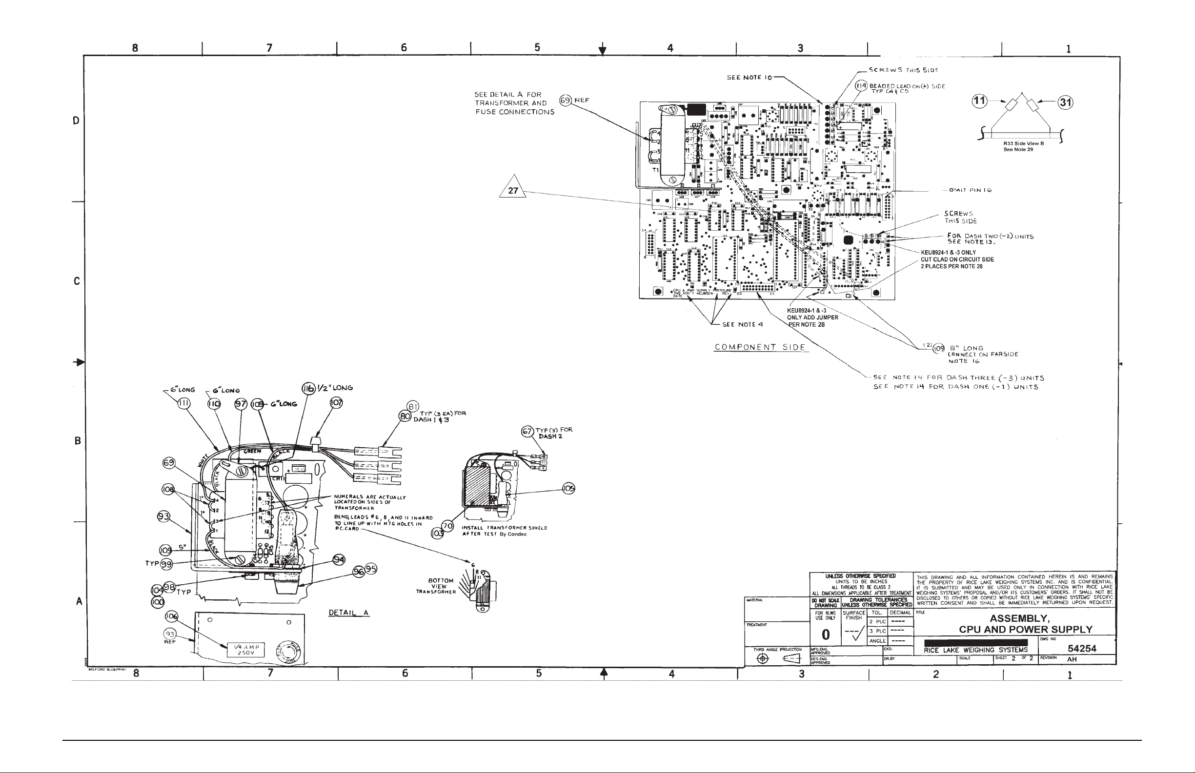
Figure 4-6. CPU and Power Supply Assembly, Sheet 1 (For Non-Battery Units Only)
Maintenance and Service
39
Page 43
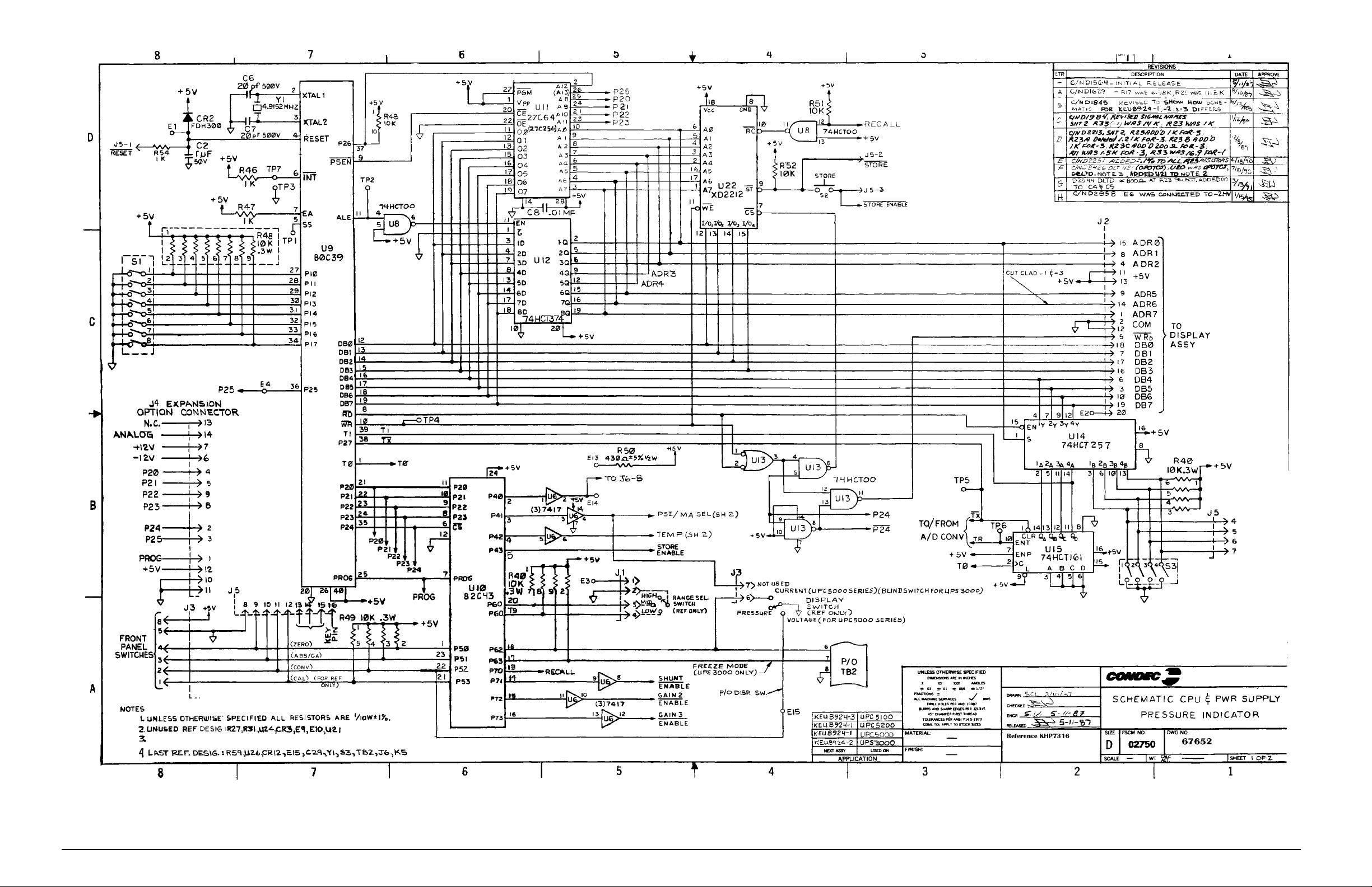
40
UPC5200/UPC5210 Operation and Maintenance Manual
Figure 4-7. Power Supply Assembly (For Battery Units Only)
Page 44
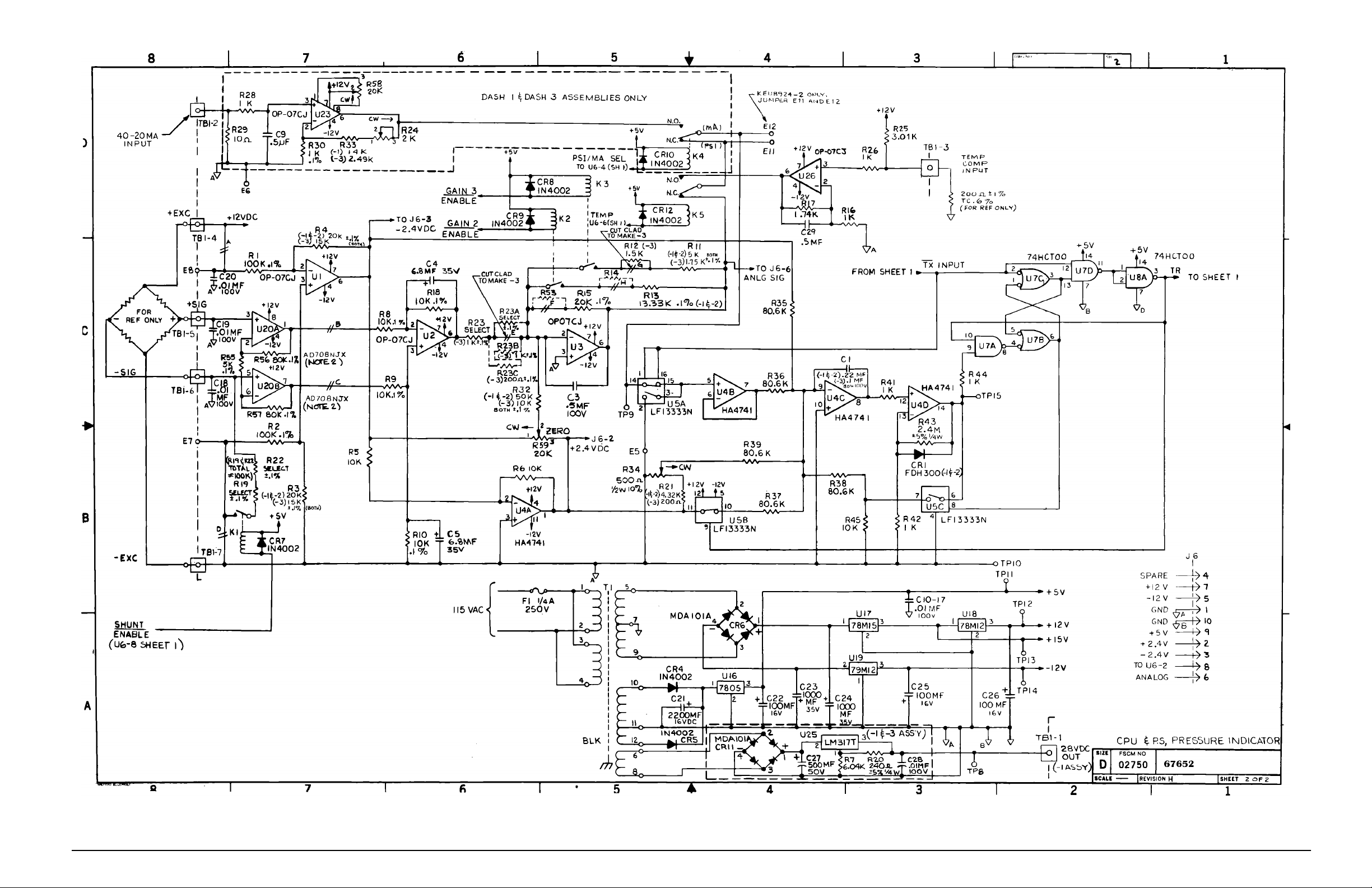
Figure 4-8. CPU Schematic, Sheet 2 (For Battery Units Only)
Maintenance and Service
41
Page 45
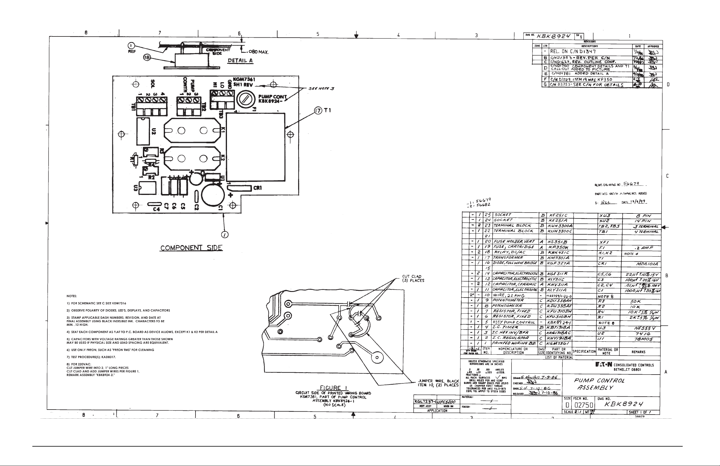
42
UPC5200/UPC5210 Operation and Maintenance Manual
Figure 4-9. Pump Control Board Assembly
Page 46
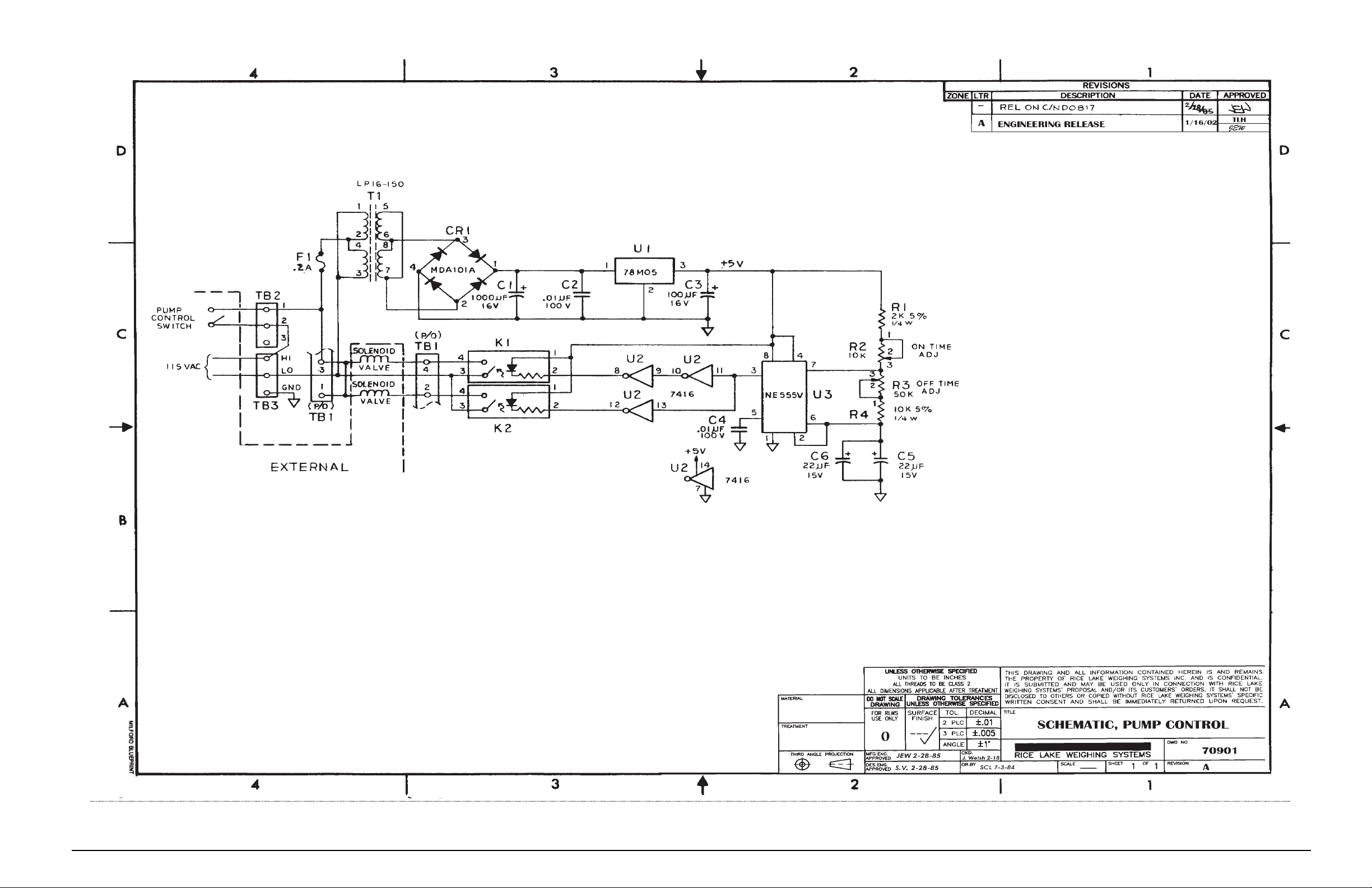
Figure 4-10. Pump Control Board Schematic
Maintenance and Service
43
Page 47

5.0 Model Number System
U P C 5 2 0 0 - ____ ____ ____
U P C 5 2 1 0 - ____ ____ ____
≠ ≠ ≠
+-------------------------------------+ ≠ ≠
≠ ≠ ≠
≠ POWER and RANGE REQUIREMENTS
≠ ≠ ≠
A - 10000/5000/2000 120 VAC * ≠ ≠
B - 5000/2500/1000 120 VAC ≠ ≠
C - 10000/5000/2000 220 VAC * ≠ ≠
D - 5000/2500/1000 220 VAC ≠ ≠
≠ ≠
+----------------------------------------------+ ≠
≠ MODE
≠ ≠
A - Gage Only ≠
B - Absolute Only ≠
≠
+------------------------------------------------------+
≠
≠ ≠
≠ DISPLAY
≠
A - Light Emitting Diode (LED)
B - liquid Crystal (LCD)
* Available in Gage Only
44 UPC5200/UPC5210 Operation and Maintenance Manual
Page 48
6.0 Ranges and Resolutions
NOTE: Display resolution, 0.02% of selected range, unless it is not devisable by 1, 2, or 5.
RANGE (PSI)
HI/MED/LO
10000/5000.0/2000.0
5000.0/2500.0/1000.0
Calibrator Mode
Gage Only
Gage Only or
Absolute Only
Table 6-1. Ranges and Resolutions
RESOLUTION
HI/MED/LO
2/1/0.5
1/0.5/0.2
Ranges and Resolutions 45
Page 49

7.0 Options, Replacement Kits
There are numerous replacement part numbers mentioned throughout manual that can be ordered.
ORION-3A O-Ring Replacement Kit (Data Sheet # 65370):
• Fluorocarbon “Viton” (standard)...........................................................PN 55277
•Nitrile Buna-N.......................................................................................PN 58499
• Ethylene-Propylene ...............................................................................PN 58506
• Silicone..................................................................................................PN 58509
•Neoprene...............................................................................................PN 58515
Note: A small coating of Fluorinated Krytox grease, (PN 55593), should be applied to both sides of
O-ring prior to installation.
• Pressure Trap (Data Sheet # 58596)......................................................PN 58478
•Test Port (output) Quick-Disconnect Male Hose fitting........................PN 55542
• Input Port Hose Nitrogen Bottle Mating fitting (one each of the following)
Cheat Seal Pad...................................PN 54854
Hose Adapter fitting..........................PN 60803
CGA-580 Nipple...............................PN 57150
CGA-580 Nut....................................PN 57154
Note: For Input Port Quick-Disconnect Female Hose fitting assembly instructions see
Section 4.2.19 on page 29.
Test Port (output) Hose, with Quick-Disconnect Male fitting:
• 5' Long...................................................................................................PN 55280
Input Port Hose, with Nitrogen Bottle Mating fitting:
• 4' Long...................................................................................................PN 55360
• 10' Long.................................................................................................PN 55366
• 15' Long.................................................................................................PN 55369
• 20' Long.................................................................................................PN 55375
46 UPC5200/UPC5210 Operation and Maintenance Manual
Page 50

8.0 Specifications
Pressure Specifications:
Pressure range: Three independent pressure ranges
Available pressure
calibrations: Gage only or absolute only,
Overall accuracy: < ±0.05% Full Scale Max. Accuracy
Operating Temp: +40° to +122°F (+4.4° to +50.0° C)
Storage Temperature: 0° to +185° F (–17.8° to +85°C)
Pressure Media: Dry gaseous nitrogen, standard
External Pressure Cylinder, UPC5200 only:
Capacity: 83.3 ft
Volume: 960 in
Rating: 2,216 psig
Test Pressure: 3,694 psig
Material: Aluminum
Regulated Pressure Gage:
Size: 2-1/2 in. diameter
Range: 5K model 0–600 PSIG,
Test Pressure: 5K model 900 PSIG,
Accumulator Gage:
Size: 2-1/2 in. diameter
Range: 5K model 0–6,000 PSIG,
Test Pressure: 5K model 9,000 PSIG,
Over-pressure Rupture Disk:
Rating: 3,000 PSIG, nominal
Type: Stainless steel outer case
Pressure Media Filter:
Rating: 20 microns, Test Port and Input Port
Type: Field replaceable
ORION-3A Control Valve:
Type: Micro-metering with replaceable soft
Material: Aluminum knobs, black anodized
Relief Valve:
Type: Adjustable, atmospheric bleed
Setting: Adjustable, set between 525-550
Material: 300 series Stainless Steel.
per instrument. See Section 5.0 on
page 44 for available ranges.
statement includes all effects of
linearity, hysteresis, repeatability and
ambient temperature
3
N2 @ 2,216 PSIG
3
10K model 0–3,000 PSIG
10K model 4,500 PSIG
10K model 0–15,000 PSIG
10K model 22,500 PSIG
40 microns, Test Port Hose
seat
All other parts 300 series stainless
steel
PSIG
Internal Piping:
Tubing: 1/8 in. O.D., 0.035 in. wall thickness,
Couplings: Stainless Steel, Swagelok type
Input Port:
Style: 1/4" 37° AN flare male
Pressure Rating: 2216 PSIG connected
Material: 300 series Stainless Steel
Test Port:
Pressure Rating: 10,000 PSIG.
Material: 300 series Stainless Steel
Vent Port:
Style: 1/4" 37° AN male
Pressure Rating: 10,000 PSIG
Material: 300 series Stainless Steel
Pressure Hoses:
Quantity Supplied: Two; one input, one output
Length: 4 ft. nominal, input hose
Style: Input hose
Regulator:
Type: Single stage, self-venting, non-bleed
Pressure Rating: 3,000 PSIG max. inlet
Internal Pressure Sensor:
Type: Bonded, metal foil strain gage,
Sensitivity: 3 mV/V nominal.
Construction: Completely weld-sealed Stainless
Carrying Case UPC5200 only:
Type: Aluminum case with latched cover and
Material thickness: 0.090 in., nominal
Finish: Enamel paint, textured finish
Color: Gray
seamless Cu.
1/4 in. O.D., 0.035 and 0.065 in. wall
thickness, seamless 304 Stainless
Steel
5 ft. nominal, output hose
with synthetic fiber braid and polyester
cover. Fitted with CGA-580 (Brass)
nipple fitting on one end and 1/4" 37˚
female AN swivel pressure fitting on
opposite end.
Output hose
with synthetic fiber braid and
polyurethane cover. Fitted with
quick-disconnect plug (St Stl) on one
end and 1/4" 37˚ female AN swivel
tube coupling on the other.
sputtered thin-film or equivalent.
Steel outer body and pressure
cavity.
handle
- Nylon-lined core tube
- Nylon-lined core tube
Specifications 47
Page 51

Control Panel:
Material: Aluminum (5052-H32)
Thickness: 0.125 in.
UPC5200 Finish: Gray enamel paint with black
silkscreen nomeclature
UPC5210 Finish: Dark Tan enamel paint with black
silkscreen nomenclature
Physical Specifications:
Weight: 52 lbs. including all hoses and cables.
UPC5200 Case Dim’s: 11" wide x 18" long x 11.5" high
UPC5210 Case Dim’s: 19" wide x 8.1" deep x 10.5" high
(Case Dimensions excluding front handles).
48 UPC5200/UPC5210 Operation and Maintenance Manual
Page 52

UPC5200/UPC5210 Warranty and Return Policy
If possible, please save original packing material which is specifically designed for the unit. Should it be
necessary to ship the unit back to the factory, a suitable shipping container must be used along with sufficient
packing material. Do not put a shipping label on the unit as a "suitable shipping container." Some units ha v e been
severely damaged this way. This is a delicate, precision instrument. Any damage incurred because of poor
packaging procedures will ultimately result in added service charges and longer turn-around times.
Caution
!
When factory service is required, send in only the unit for repair. Retain fittings, manuals, etc. at your facility.
However, if there is a problem with a particular part, send in that part with the unit.
If a unit is found to be defective, it may be returned to our repair facility at the following address:
CONDEC
3 SIMM LANE
DOOR D, UNIT 2A
NEWTOWN, CT 06470
ATTN: PRESSURE PRODUCTS/REPAIR LAB
Each unit's I.D. plate is stamped with a date code (week/year) prior to shipment. Our warranty is twelve (12)
months from that date code and includes repair and/or replacement of the unit at our, Newtown facilities at no
charge. Units subjected to abuse or damaged by external influences, are not covered under warranty.
If the unit is found to be out of warranty, an evaluation charge of not less than fifty (U.S.) dollars ($50.00) will be
charged. Please note on any attached paperwork if a repair estimate is required or if there are any other specific
instructions.
Vent all pressure lines and the nitrogen cylinder to the atmosphere before shipping.
Please be explicit as to the nature of the problem and/or its symptoms. Your documentation will save needless
time and expense. Also, please include a return shipping address (with a street address) and a contact name with
fax and telephone numbers. Contact numbers are necessary to provide a job estimate and in case further
questions arise at the factory.
UPC5200/UPC5210 Warranty and Return Policy 49
Page 53

UPC5200/UPC5210 Return Material Authorization Form
The repair lab is also equipped to do calibrations on our calibrators and pressure standards. Calibrations include
a certification and are traceable to N.I.S.T.
COMPANY NAME:
STREET:
CITY, STATE, ZIP:
TELEPHONE:
FAX:
CONTACT PERSON:
MODEL NUMBER:________________ SERIAL NUMBER: _______________________________
PROBLEM WITH UNIT (PLEASE BE SPECIFIC):
IS THIS A WARRANTY REPAIR? ( ) YES ( ) NO
SHIP TO Address:
COMPANY NAME:
STREET:
CITY, STATE, ZIP:
ATTN:
CONDEC • 3 SIMM LANE • DOOR D, UNIT 2A • NEWTOWN, CT 06470
ATTN: PRESSURE PRODUCTS/REPAIR LAB
TEL: 888-295-8475 • FAX: 203-364-1556 or 715-234-6967
WEB SITE: www.4condec.com
50 UPC5200/UPC5210 Operation and Maintenance Manual
 Loading...