

Page 1
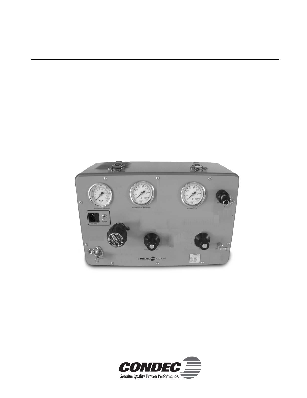
PIN7000 & PIN7010
Portable & Rack-mountable Pneumatic
High Pressure Intensifier Console
Operation and Maintenance
Manual
CONDEC Sales Phone No.: (888) 295-8475
CONDEC Web Site: WWW.4CONDEC.COM
63258
Page 2

Page 3

Contents
About This Manual ................................................................................................................................... 1
1.0 Introduction.................................................................................................................................. 1
2.0 Operation...................................................................................................................................... 3
2.1 Optional External Pressure Cylinder (PN 59533) Filling Procedure . . . . . . . . . . . . . . . . . . . . . . . . . . . 3
2.2 Initial Setup Procedure. . . . . . . . . . . . . . . . . . . . . . . . . . . . . . . . . . . . . . . . . . . . . . . . . . . . . . . . . . . . 3
2.3 Operating Instructions . . . . . . . . . . . . . . . . . . . . . . . . . . . . . . . . . . . . . . . . . . . . . . . . . . . . . . . . . . . . 4
3.0 Maintenance & Service ............................................................................................................... 5
3.1 Troubleshooting. . . . . . . . . . . . . . . . . . . . . . . . . . . . . . . . . . . . . . . . . . . . . . . . . . . . . . . . . . . . . . . . . 5
3.2 Maintenance & Service Procedures . . . . . . . . . . . . . . . . . . . . . . . . . . . . . . . . . . . . . . . . . . . . . . . . . . 5
3.2.1 Panel/Chassis Removal and Installation . . . . . . . . . . . . . . . . . . . . . . . . . . . . . . . . . . . . . . . . . . . . . . . . 6
3.2.2 Accumulator, Intensifier & MPV Valves (PN 65076) Removal . . . . . . . . . . . . . . . . . . . . . . . . . . . . . . . . . 7
3.2.3 MPV Valve, Valve Seat Removal . . . . . . . . . . . . . . . . . . . . . . . . . . . . . . . . . . . . . . . . . . . . . . . . . . . . . . 8
3.2.4 MPV Valve, Valve Seat Installation. . . . . . . . . . . . . . . . . . . . . . . . . . . . . . . . . . . . . . . . . . . . . . . . . . . . . 8
3.2.5 Accumulator, Intensifier and MPV Valves, Panel Installation. . . . . . . . . . . . . . . . . . . . . . . . . . . . . . . . . . 9
3.2.6 MPV Pressure Valve, Adjustment Procedure. . . . . . . . . . . . . . . . . . . . . . . . . . . . . . . . . . . . . . . . . . . . . 9
3.2.7 MPV Vent Valve, Adjustment Procedure . . . . . . . . . . . . . . . . . . . . . . . . . . . . . . . . . . . . . . . . . . . . . . . 10
3.2.8 Accumulator Assembly, O-ring (PN 58051) Replacement, Filter (PN 56993) Cleaning . . . . . . . . . . . . . 11
3.2.9 Intensifier Assembly, O-rings/Seals Replacement . . . . . . . . . . . . . . . . . . . . . . . . . . . . . . . . . . . . . . . . 11
3.2.10 Regulator (Standard Pneumatic) and Solenoid Removal . . . . . . . . . . . . . . . . . . . . . . . . . . . . . . . . . . . 14
3.2.11 Regulator (Standard Pneumatic) and Solenoid Installation. . . . . . . . . . . . . . . . . . . . . . . . . . . . . . . . . . 14
3.2.12 Panel Gauge Removal and Installation . . . . . . . . . . . . . . . . . . . . . . . . . . . . . . . . . . . . . . . . . . . . . . . . 15
3.2.13 Test Port Quick-Connect Fitting (PN 59004) and Filter (PN 54188), Removal and Installation . . . . . . . 15
3.2.14 Test Port (output) Hose Quick-Connect Fitting and Filter (PN 56991), Removal and Installation . . . . . . 16
3.2.15 Input Port Filter (PN 54188), Removal and Installation . . . . . . . . . . . . . . . . . . . . . . . . . . . . . . . . . . . . . 16
3.2.16 Input Port Hose Quick-Disconnect Female Fitting, Removal and Installation . . . . . . . . . . . . . . . . . . . . 17
3.2.17 AC Fuse (PN 57472), Removal and Installation . . . . . . . . . . . . . . . . . . . . . . . . . . . . . . . . . . . . . . . . . . 17
3.2.18 Panel Mounted AC Power/EMI Line Filter (PN 58870), Removal and Installation . . . . . . . . . . . . . . . . . 18
3.2.19 Power Switch (PN 60307), Removal and Installation . . . . . . . . . . . . . . . . . . . . . . . . . . . . . . . . . . . . . . 18
3.2.20 Pump Control Board Assembly, Removal and Installation . . . . . . . . . . . . . . . . . . . . . . . . . . . . . . . . . . 18
3.3 MPV Valve Assembly (PN 65076) Parts List. . . . . . . . . . . . . . . . . . . . . . . . . . . . . . . . . . . . . . . . . . . 20
3.4 Intensifier Assembly Parts List . . . . . . . . . . . . . . . . . . . . . . . . . . . . . . . . . . . . . . . . . . . . . . . . . . . . . 21
4.0 Model Number System .............................................................................................................. 27
5.0 Options, Replacement Kits ........................................................................................................ 28
6.0 Specifications............................................................................................................................ 29
PIN7000/PIN7010 Warranty and Return Policy ..................................................................................... 30
PIN7000/PIN7010 Return Material Authorization Form ........................................................................ 31
© 2005 Rice Lake Weighing Systems. All rights reserved. Printed in the United States of America.
Specifications subject to change without notice.
Version 2.0, June 2005
Page 4

Page 5
About This Manual
This manual is intended for use by service technicians responsible for installing and servicing PIN7000/PIN7010
pressure intensifiers.
The PIN7000 portable pneumatic pressure intensifier and the rack-mounted PIN7010 are rugged, compact
instruments manufactured by Condec. They are designed for custom use and ease of operation.
This manual has been written to give the user a simple and clear explanation of how to operate and maintain
these instruments.
Before attempting to use either style pressure intensifier, the following instructions must be carefully
#AUTION
These units are strictly for use with pneumatic pressures. Erroneous readings and potential damage can result from the
introduction of hydraulic fluids into the internal tubing lines.
read and understood by personnel using the equipment. This is a high-pressure system. It is strongly
recommended that only personnel formally trained in the use of pneumatic pressure equipment be
permitted to operate it. Potentially dangerous conditions can be produced through negligent
handling or operation of the console due to the high pressure output of the unit.
Authorized distributors and their
employees can view or download this
manual from the Condec distributor site
www.4condec.com.
at
1.0 Introduction
The PIN7000/PIN7010 pressure intensifier is an electro-mechanical device that utilizes our precision MPV type
micro-metering valves for pressure adjustment and venting. The unit has one test port, one input port and three
front panel gauges, for the operator to monitor accumulator pressure, regulated input pressure, and intensified
output pressure. The pressure regulator acts as a pressure limiter so that the operator can adjust input system
pressure to 1/10 of the target value. Fill and test hoses are supplied for the customer. A front panel switch
provides selection of the desired pump control mode, momentary (jog) or co ntin uo us. Fo r field u se, the PIN7000
has a optional 83.3 cubic foot, 2,216 PSI cylinder available to provide many hours of use.
The PIN7000 and rack-mounted PIN7010 instruments offer a combination of features, performance, versatility
and reliability not previously available in a pressure intensified instrument. Some of the features are listed below:
• Switch-selectable pressure pump control mode, momentary (jog) and continuous.
• Pressure monitoring: Three front panel mounted gauges provide excellent readability.
• Using a manua lly adjustable regulator, the maximum system input pressure is adjusted to slightly above
1/10 desired value of the full scale range of the device being tested. By using this technique, the device
that is to be pressurized is fully protected from being inadvertently over-pressurized.
• Portable: These compact, self-contained systems are easily carried and operated by only one person.
Total weight is approximately 38 lbs.
• P ressure Source: Nitrogen or clear dry air is supplied by the customer. In either instrument, the pressure
source drives a pneumatically operated 10 to 1 intensifier contained within the PIN7000/PIN7010.
Therefore, a 1,000 PSI input is amplified to 10,000 PSI. An optional external supply cylinder may be
purchased that will contain a volume of 83.3 standard cubic feet off nitrogen and provide up to 2,216
PSIG of pressure for calibration and test.
• S imple Operation: All controls, indicators and pressure ports (PIN7000 only) are accessible from the
front panel. Accompanying operator's manual provides clear, concise instructions for system operation.
• S afe, Clean Operation: All pressure components are made of stainless steel and proof-tested to at least
150% of maximum operating pressure. In addition, the system contains a high-pressure burst disk to
protect both the operator and system components from harm in the event of inadvertent
over-pressurization.
Introduction 1
Page 6
In addition to the features, the PIN7000/PIN7010 pressure intensifier is easy to use. Two MPV style
micro-metering valves are provided to control the internally intensified nitrogen while the output pressure gauge
indicates the magnitude of the applied test pressure. Over-pressure protection is provided through a
fully-adjustable pressure regulator, which is manually set for each new device being tested.
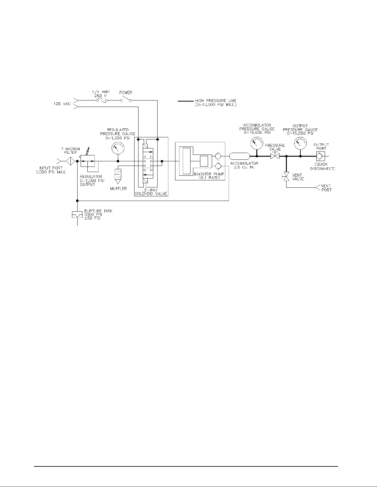
Figure 1-1 provides an overview of the PIN7000/PIN7010’s function.
Figure 1-1. PIN7000/PIN7010 Flow Diagram
2 PIN7000/PIN7010 Operation and Maintenance Manual
Page 7

2.0 Operation
2.1 Optional External Pressure Cylinder (PN 59533) Filling Procedure
NOTE: Condec strongly recommends that the external nitrogen supply cylinder be pressure-tested and re-certified
every five years from date cylinder was manufactured per U.S. DOT. 3AL Regulation, Title 49 CFR, parts 173 and 178.
To initially fill or refill the external pressure cylinder (2,216 PSI max.), proceed as described below.
1. Close the CYLINDER valve by rotating clockwise until it stops.
2. Connect the customer supplied fill hose, to a clean regulated nitrogen source, with an output pressure
gauge and vent valve.
3. Connect the other end of the customer supplied fill hose to the female CGA-580 brass CYLINDER valve
fitting.
4. Open the CYLINDER valve by rotating counter-clockwise until it stops.
5. Slowly open the valve on the nitrogen source and allow the gas to flow into the pressure cylinder. The
customer supplied output pressure gauge indicates the amount of pressure within the internal cylinder.
NOTE: Cylinder is equipped with a rupture disk.
6. Use the following procedure to fill the cylinder:
a) Fill cylinder to 1,000 PSI at a rate of charge equal to a minimum of two minutes, then wait five
minutes for system to stabilize.
b) Fill cylinder from 1,000 PSI to 2,216 PSI at a rate of charge equal to a minimum of two minutes.
c) Wait five minutes for cylinder to stabilize before using.
7. Close the CYLINDER valve by rotating clockwise until it stops.Vent nitrogen source and remove fill hose.
2.2 Initial Setup Procedure
To prepare for actual intensifier usage, see Figure 2-1 below and proceed as follows:
1. Check that the PRESSURE valve (11) is closed (rotate clockwise until it stops) and that the Vent valve
(12) is open (two turns counter-clockwise from its stop). Verify that the REGULATOR (10) is closed
(rotate counter-clockwise until it stops).
2. Plug in the power cord (1).
3. Connect the male end of the test hose to the TEST PORT (9) fitting.
4. Connect the swivel fitting end (7/16-20) of the test (output) hose to the input of the device to be
pressurized using adapters if required. Tighten all connections properly.
5. Optional External Cylinder: Connect the male end of the input hose (3) to the female CGA-580 brass
CYLINDER (5) valve fitting.
Other: Connect the male end of the input hose (3) to the female CGA-580, customer supplied, pressure
source.
6. Connect the swivel fitting end (7/16-20) of the input hose (3) to the INPUT PORT (4) fitting. Tighten all
connections properly.
Operation 3
Page 8
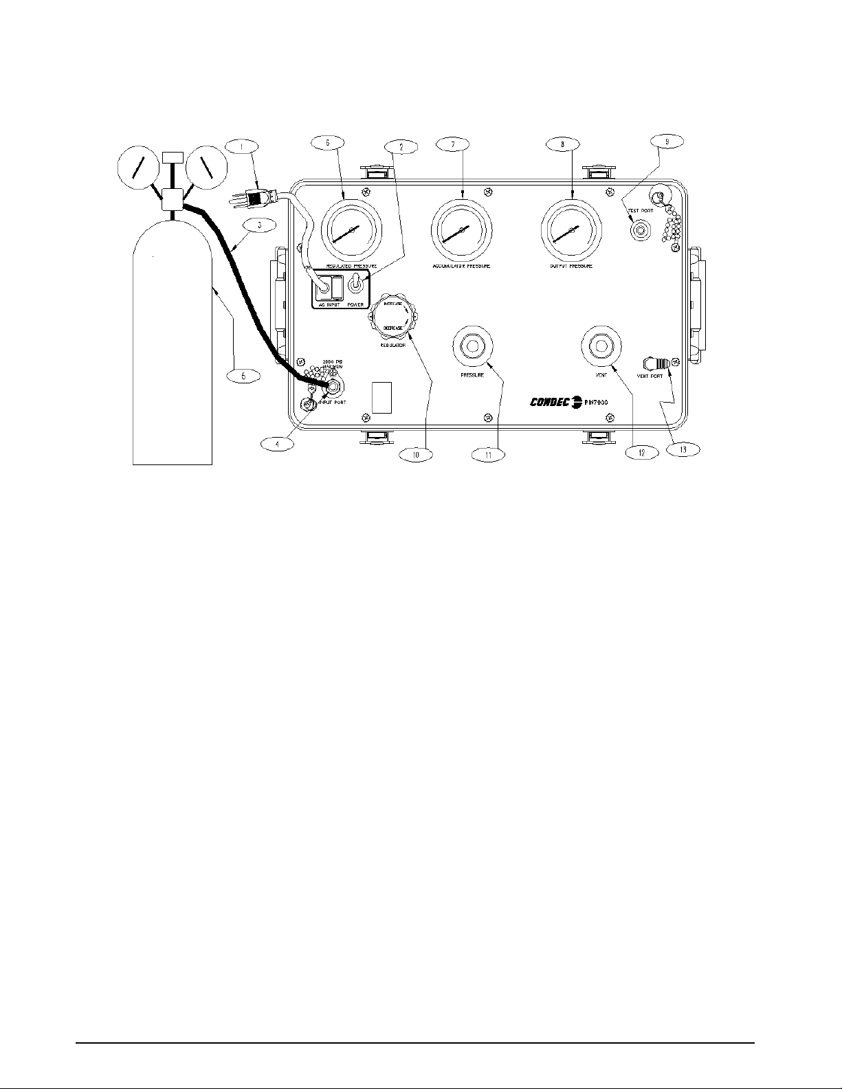
Figure 2-1. Initial Setup/Operating
NOTE: PIN7000 shown, AC Input (1), Test Port (9) and Input Port (4) are on back side of PIN7010 Rack Mountable
Intensifier.
2.3 Operating Instructions
NOTE: See Figure 2-1, when following these steps.
1. Optional External Cylinder: Open the cylinder valve (5) by rotating counter-clockwise slowly until it
stops.
Other: Open the, customer supplied, pressure source valve.
2. Using the REGULATOR (10), adjust the maximum intensifier pump input pressure, as read by the
REGULATED PRESSURE gauge (6), to 1/10 of the target value. The unit utilizes an internal intensifier
with a 10:1 ratio. As an example, setting regulated pressure to 300 PSI would generate an output pressure
of 3,000 PSI. Using this technique, the device to be pressurized, is fully protected from being
accidentally over-pressurized.
3. To generate pressure, enable the POWER switch (2) and monitor the pressure as it builds in the
ACCUMULATOR PRESSURE gauge (7). Turn the
target pressure has been achieved.
NOTE: The intensifier POWER switch (2) can be operated in two modes. The up position is continuous and the down
position is momentary/jog.
4. To apply pressure, the VENT valve (12) must be closed. Open the PRESSURE valve (11), slowly
counter-clockwise, while monitoring the
OUTPUT PRESSURE gauge (8), until reaching the target value.
5. Use either the PRESSURE (11) or VENT valve (8) to obtain a specific pressure reading. Both provide
precise control. As the pressure approaches the desired value, the valve being used for control should be
rotated slowly clockwise to its closed position.
NOTE: Use the intensifier POWER switch (2) if the ACCUMULATOR PRESSURE gauge (7) reading falls below required
target pressure value.
POWER switch (2) off when 10% more than the
4 PIN7000/PIN7010 Operation and Maintenance Manual
Page 9
3.0 Maintenance & Service
This section outlines the mechanical and basic electrical repair procedures for the PIN7000/PIN7010.
3.1 Troubleshooting
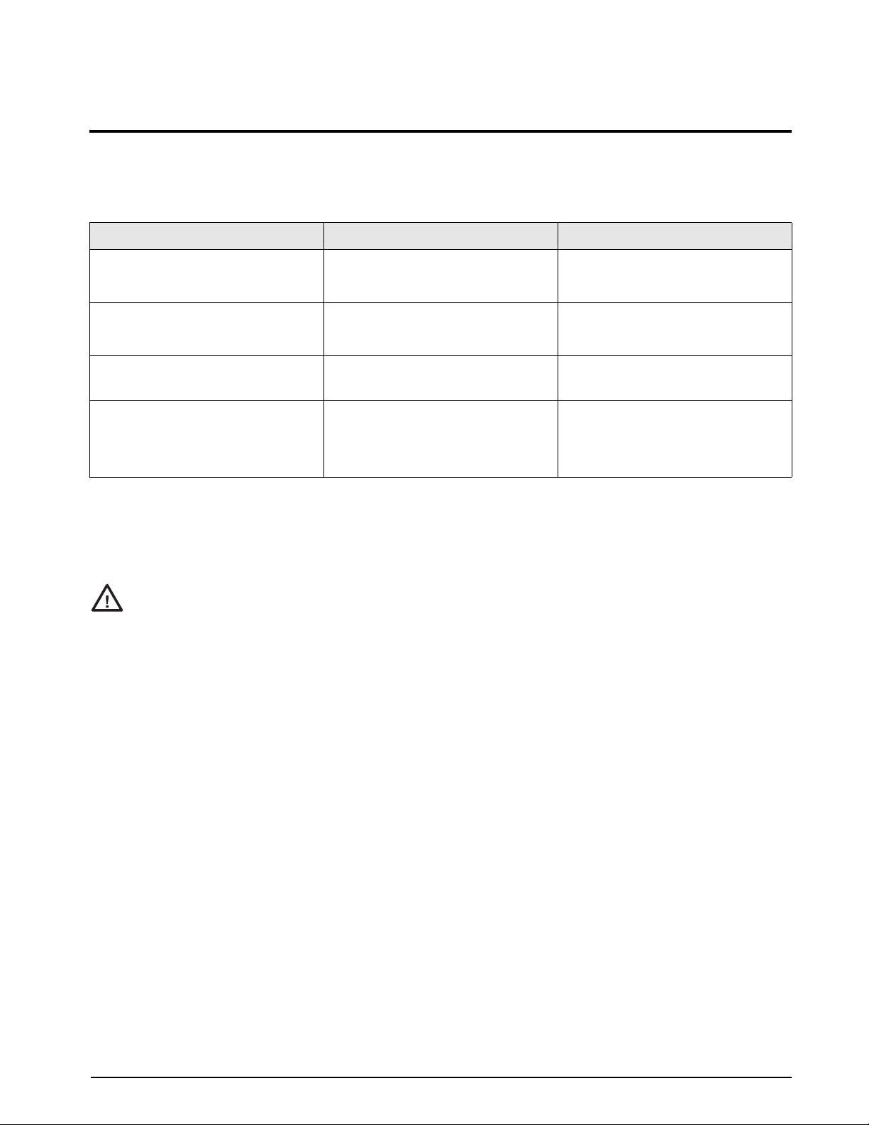
Use T able 3-1 below for information on troubleshooting the PIN7000/PIN7010.
Symptom Problem Remedy
OUTPUT PRESSURE gauge slowly
decreases over time.
OUTPUT PRESSURE gauge increases
or decreases when OUTPUT
PRESSURE or VENT valves are closed.
Unit does not cycle when Pump Control
switch is on.
Unit cycles, but does not pressurize. Debris in check valve seat in intensifier,
Leak in system. Check all compression and pipe fittings
with Snoop®, bottle of liquid leak gas
detector (PN 64781).
No Pressure or Vent control. Replace valve seats or O-rings in valves;
check valve needles.
Fuse blown on Pump Control Board.
No power.
deformity in seat.
No supply pressure.
Replace fuse.
Check that power is on.
Remove seats in intensifier and clean
and/or replace.
Check to see if there is sufficient supply
pressure.
Table 3-1. PIN7000/PIN7010 Troubleshooting
3.2 Maintenance & Service Procedures
The repair procedures cover the major components and sub-assemblies which are critical to the proper
functioning of the calibrators and that need periodic maintenance over the life of the unit.
Only those persons who are formally trained as skilled technicians should attempt to repair these units.
#AUTION
All safety precautions should be observed due to the presence of electrical and high-pressure
components. Unit must always be unplugged from power source and vented.
®
Snoop is a registered trademark of ....
Maintenance & Service 5
Page 10

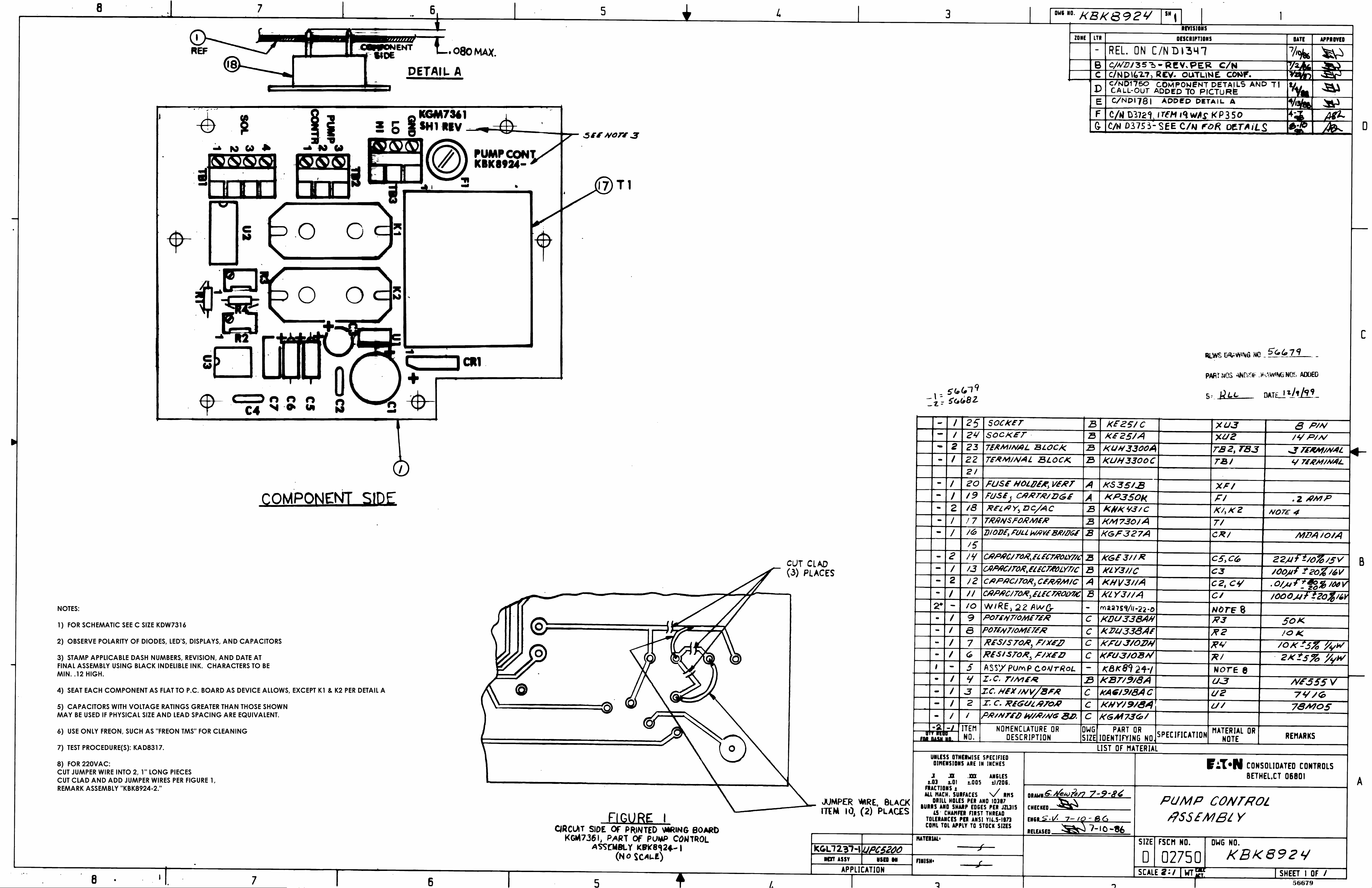
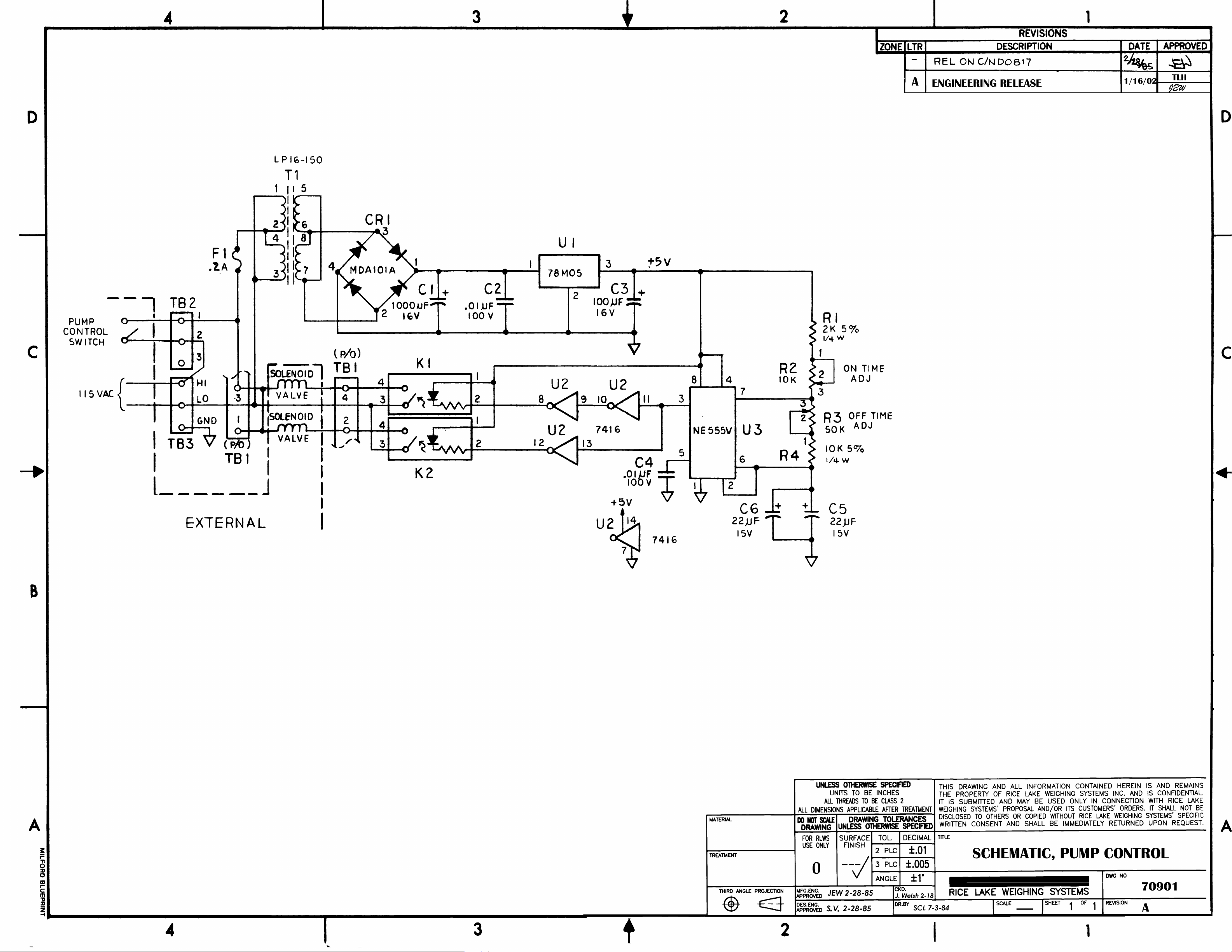
Figure 3-1. PIN7000/PIN7010 Wiring Diagram
3.2.1 Panel/Chassis Removal and Installation
PIN7000 Removal
Tools required: Phillips screwdriver
1. Loosen and remove the 10 screws (PN 14862) that secure the panel assembly to the enclosure.
2. Lift the panel and chassis by first grasping the regulator knob and test port and second, grasping under
the panel edges. Tilt the panel at an angle by lifting the right side before the left side as you face the
panel. Ensure that the wire harnesses do not catch and snag.
3. Gently set the panel/chassis assembly on a bench top. It can be rested on the panel bottom with the
accumulator supported by a screwdriver handle.
PIN7000 Installation
Tools required: Phillips screwdriver
1. Lift the panel and chassis by first grasping the regulator knob and test port.
2. Gently place panel/chassis assembly into enclosure. Tilt the panel at an angle by lifting the right side
before the left side as you face the panel. Ensure that the wire harnesses do not catch and snag.
3. Align mounting holes and install the 10 screws (PN 14862) that secure the panel assembly to the
enclosure.
PIN7010 Removal
Tools required: Phillips screwdriver
1. Loosen and remove the 14 screws (PN 14861) from top, bottom, and sides that secure the panel assembly
to the enclosure. Also, loosen and remove the three screws (P/N 14861) from the rear of unit that secure
the enclosure to the TEST PORT/AC INPUT/INPUT PORT panel.
2. Lift the panel and chassis by grasping the handles located on the front of the rack mountable panel.
Ensure that the wire harnesses do not catch and snag.
3. Gently set the panel/chassis assembly on a bench top. It can be rested on the panel bottom with the
accumulator supported by a screwdriver handle.
PIN7010 Installation
Tools required: Phillips screwdriver
1. Lift the panel and chassis by grasping the handles located on the front of the rack mountable panel.
6 PIN7000/PIN7010 Operation and Maintenance Manual
Page 11

2. Gently place panel/chassis assembly into enclosure. Ensure that the wire harnesses do not catch and
snag.
3. Align mounting holes and install 14 screws (PN 14862) from top, bottom, and sides that secure the
panel/chassis assembly to the enclosure. Also, align mounting holes and install the three screws (PN
14862) from the rear of unit that will secure the enclosure to the TEST POR T/AC INPUT/INPUT PORT
panel.
3.2.2 Accumulator, Intensifier & MPV Valves (PN 65076) Removal
Tools required: Phillips screwdriver
11/32" Wrench or nutdriver
.061" Hex wrench
7/16" Open end wrench
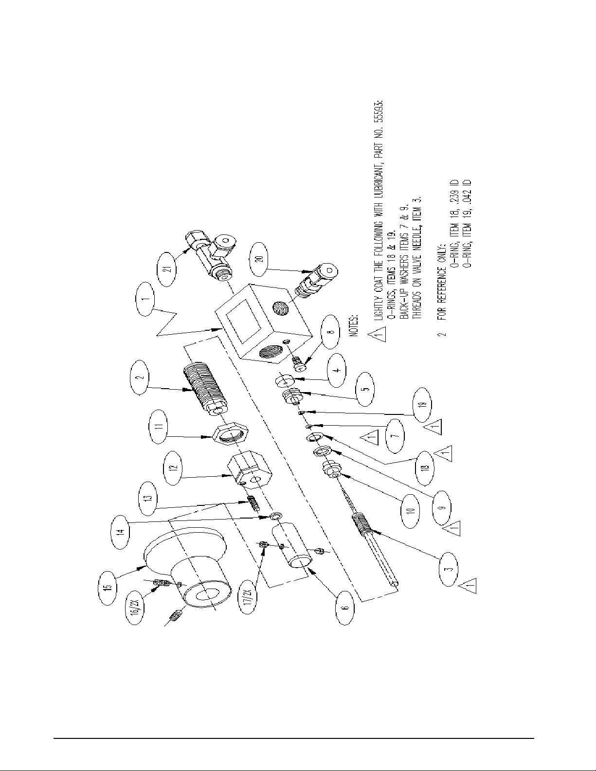
NOTE: See Table 3-2 on page 19 and Figure 3-2 on page 22 for additional MPV valve parts information. See Table 3-3
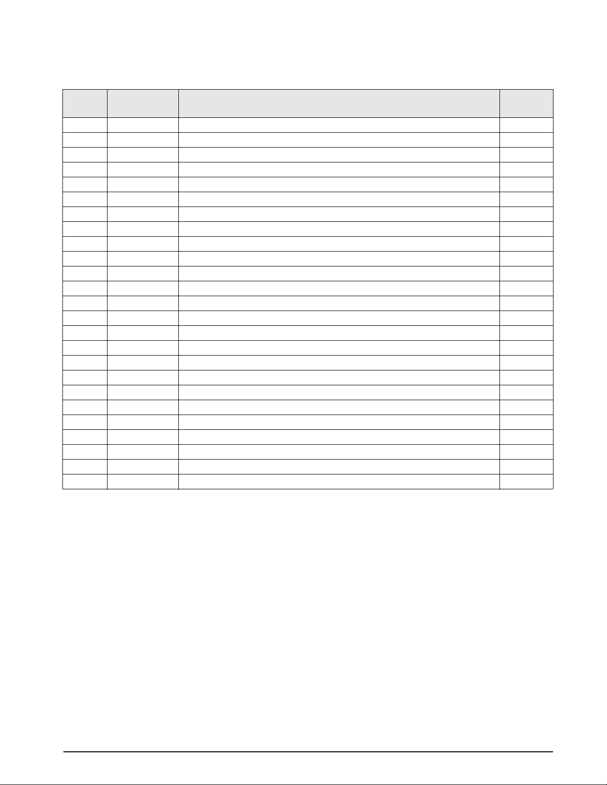
on page 21 and Figure 3-2 on page 22 for additional intensifier parts information.
1. Vent the system to atmosphere before attempting to work on the unit. Disconnect the power cord from
the power source.
2. Remove front panel from its enclosure as described in Section 3.2.1 and carefully set on a bench top.
3. Using a 7/16" wrench, remove the following tubing sections:
•Accumulator to intensifier outlet (1/4" dia.)
•Intensifier assembly to solenoid tee fitting (1/4" dia.)
•Vent valve tee to output pressure gauge (1/8" dia.)
•PIN7010 only: Pressure valve tee to test port fitting
•Accumulator to pressure valve fitting (1/8" dia.)
•Accumulator to accumulator pressure gauge (1/8" dia.)
•Pressure valve tee to vent valve tee (1/8" dia.)
4. Loosen and remove the six screws that secure the two clamps that hold the intensifier and accumulator.
5. Remove the accumulator by sliding out.
6. Loosen the fitting nut at the intensifier end of the long 1/4" diameter tubing section that connects the
solenoid valve to the intensifier. There is no need to remove the tubing.
7. Remove the two clamps and the intensifier.
8. Using a 7/16" wrench, remove the following tubing section:
• Vent port to vent valve outlet (1/8" dia.)
9. Remove the panel knobs from the Pressure and Vent valves using the .061" hex wrench.
10. Loosen and remove the two panel screws (PN 6083 7) from the panel front that secure the valves to the
panel.
11. Remove the five retaining nuts and lock washers that secure the chassis to the panel.
12. Lift the chassis enough to allow the MPV valves to clear and remove the valves.
13. Reposition the chassis over the mounting studs and secure with at least two nuts.
3.2.3 MPV Valve, Valve Seat Removal
Tools required: A/R solvent (de-natured alcohol)
Socket wrench
3/4" Socket
Needle housing socket (65580)
Hex wrench (.050")
Hex wrench (.061")
Needle-nose pliers
Tube fluorinated Krytox grease (PN 55593)
Electric hand drill
No. 43 drill bit
No. 4-40 tap
Tap handle
Small hammer
NOTE: See Table 3-2 on page 19 and Figure 3-2 on page 22 for additional parts information.
Maintenance & Service 7
Page 12

1. Secure the valve body by its center portion, in a bench vise, with the valve knob pointing upward.
2. Using the .061" hex wrench, loosen and remove the knob insert (6) and the n ylon washer (14) from the
valve stem (3).
3. Using the .050" hex wrench, loosen and remove the set screw (13) and lock nut (12).
4. Loosen the 3/4" locknut (11) on the valve threaded needle housings (2).
5. Using the needle housing socket (65580) and socket wrench, loosen and remove the needle/housing
assembly (2, 3).
6. Remove the valve stem seat (10) and valve needle seat (5) using the needle-nose pliers.
7. Remove the inner and outer O-rings (19, 18) and back-up rings (7, 9) from the valve stem seats and wash
all parts in solvent (de-natured alcohol).
8. To remove valve seat (4) from valve, blow compressed air through the inlet and outlet fittings. If this is
unsuccessful, the center hole will have to be drilled and a tap used to extract the seat (steps 9-12).
9. Using the hand drill with the No. 43 bit, carefully drill out the seat hole, ensuring that the drill does not
touch the hole in the valve body housing directly beneath the seat.
10. Blow out any chips from the seat area using compressed air.
11. While holding the 4-40 tap steady and perpendicular to the seat, slowly turn until the tap starts to engage
the seat.
12. When the tap has engaged into the seat, use a small hammer and gently knock upward aga inst the tap
handle to extract the seat.
13. After the seat has been removed, blow any remaining chips from the seat area.
3.2.4 MPV Valve, Valve Seat Installation
Tools required: Needle-nose pliers
Tube fluorinated Krytox grease (PN 55593)
No. 43 drill
A/R solvent (de-natured alcohol)
Hex wrench (.050")
Hex wrench (.061")
Torque wrench
Socket wrench
3/4" Socket
Needle housing socket (PN 65580)
NOTE: See Table 3-2 on page 19 and Figure 3-2 on page 22 for additional parts information.
1. Install a new seat (4) by placing it into the seat well with the needle-nose pliers. Ensure that the seat is
centered within the cavity and gently tap it with a blunt end of a drill bit to install.
2. Install the valve needle seat (5) with the smaller diameter end facing outward.
3. Install new O-rings (19, 18) and back-up rings (7, 9) inside and outside of the valve needle seat. Coat all
O-rings and back-up rings with fluorinated Krytox grease before installation. Make sure that the rings
are installed in the proper order.
4. Install the valve stem seat (10) by grasping the small diameter end with the needle-nose pliers and
positioning in the valve cavity, then gently pushing with the blunt end of a drill bit.
5. Disassemble the valve needle (3) from its housing (2) and check for any burrs or dirt on the threads
which might interfere with smooth operation.
6. Clean both the needle (3) and housing (2) in solvent, dry the parts and apply a small amount of
fluorinated Krytox grease to the needle threads before reassembly.
7. Assemble the Valve Needle (3) into the valve needle housing (2) and turn it until it stops.
8. Reinstall the needle/housing assembly into the valve cavity until finger tight.
9. Mount the valve body (1) in a vise. Torque the needle/housing assembly to 325 in-lb. using the needle
housing socket (PN 65580) and torque wrench.
10. Install the housing lock nut (11) onto the housing (2) and tighten until snug with the 3/4" socket.
11. Using the .050" hex wrench, install and tighten the lock nut (12) and set screw (13).
12. Install the nylon washer (14) and knob insert (6) over the valve needle (3) shaft, align the set screws (17)
with the indents and tighten with the .061" hex wrench.
8 PIN7000/PIN7010 Operation and Maintenance Manual
Page 13

3.2.5 Accumulator, Intensifier and MPV Valves, Panel Installation
Tools required: 7/16" open end wrench
Phillips screwdriver
Hex wrench (.061")
Snoop, liquid leak gas detector (PN 64781)
11/32" Open end wrench (thin)
NOTE: See Table 3-2 and Figure 3-2 on page 22 for additional parts info (* denotes reference to Figure 2-1 on page 4).
1. If not already done, remove the panel knobs from the PRESSURE and VENT valves using the .061" hex
wrench.
2. With the panel facing down against the bench, if not already done, remove the five retaining nuts and
lock washers that secure the chassis to the panel. Lift up the chassis enough so that the MPV va lves are
able to clear.
3. Install the two mounting screws (PN 60837) from the panel front and tighten until snug.
4. Secure the chassis to the panel with the five nuts and lock washers (tighten until snug).
5. Install the MPV valve knob (15) onto the knob insert (6). Repeat for other MPV valve knob. Align the
set screws (16) with the indentations on the knob insert and tighten until snug using the .061" hex
wrench.
NOTE: To perform the valve adjustments, follow the procedure in Section 3.2.6 and 3.2.7 after completing the following
steps.
6. Using a 7/16" wrench, install the following tubing section that goes from vent port to MPV vent valve
outlet (1/8" dia.).
7. Replace the intensifier and the two clamps.
8. Realign and tighten the fitting nut at the intensifier end of the long 1/4" diameter tubing section that
connects the solenoid valve to the intensifier.
9. Replace the accumulator by sliding in through the clamps.
10. Thread and tighten the six screws that secure the two clamps that hold the intensifier and accumulator.
11. Using a 7/16" wrench, realign and tighten the following tubing sections:
•Pressure valve tee to vent valve tee (1/8" dia.)
•Accumulator to accumulator pressure gauge (1/8" dia.)
•Accumulator to pressure valve fitting (1/8" dia.)
•PIN7010 only: Pressure valve tee to test port fitting (1/8" dia.)
•Vent valve tee to output pressure gauge (1/8" dia.)
•Intensifier assembly to solenoid tee fitting (1/4" dia.)
•Accumulator to intensifier outlet (1/4" dia.)
12. Plug power cord into outlet. Using a pressure source connected to the input port (*4) set input pressure to
100 PSI. Open REGULATOR until REGULATED PRESSURE gauge (*6) rises to 100 PSI. Enable the
POWER switch (2) and monitor the pressure as it builds in the ACCUMULATOR PRESSURE gauge
(*2). Turn the
POWER switch (*2) off when 1,000 PSI has been achieved. Check all fittings for leaks. If
there are no leaks vent system and remove pressure source.
NOTE: See Section 2.2 on page 3 for pressure source connection procedure.
13. Install panel/chassis assembly in its enclosure as described in Section 3.2.1 on page 6.
3.2.6 MPV Pressure Valve, Adjustment Procedure
Tools required: Hex wrench (.050")
Hex wrench (.061")
NOTE: See Table 3-2 and Figure 3-2 on page 22 for additional parts information (* denotes reference to Figure 2-1 on
page 4).
1. Turn the supply pressure regulator off.
2. If not already done, remove the valve knob (15) using the .061" hex wrench.
3. Verify the power cord is plugged in.
4. Using a .050" hex wrench, loosen the set screw (13) on the MPV valve locknut (12) and turn the locknut
clockwise to its stop.
Maintenance & Service 9
Page 14

5. Check to see that the knob insert (6) is securely fastened to the valve shaft (3). If it is loose, re-tighten the
set screws (17) with the .061" hex wrench.
6. Close the PRESSURE valve by turning the knob insert (6) clockwise until you feel the valve needle seat
on the O-ring (valve is now in closed position).
7. With a pressure source connected to the INPUT PORT (*4). Use the REGULATOR (*10), to increase
the regulated pressure (monitor REGULATED PRESSURE gauge) to 1,000 PSI. Enable the
POWER
switch (2) and monitor the pressure as it builds in the ACCUMULATOR PRESSURE gauge (*7). Turn
POWER switch (2) off when above 8,000 PSI has been achieved.
the
8. Open the VENT valve (*12) to atmosphere, then close the VENT valve (*12).
9. Slowly open the PRESSURE valve by turning the knob insert (6) counter-clockwise until you notice the
OUTPUT PRESSURE gauge (*8) increase. Then turn the knob insert slightly clockwise until the
pressure stops rising.
10. Mark a radial line at the 12 o'clock position on the knob insert (6).
11. Turn the knob insert (6) clockwise to move the mark to the 6 o'clock position.
12. Turn the locknut (12) counter-clockwise until it contacts the bottom of the stop washer (14). Tighten the
set screw (13) on the locknut with the .050" hex wrench.
13. Install the PRESSURE valve knob (15) on the knob insert (6) and align the set screws (16) with the
indentations on the knob insert.
14. Tighten the set screws (16) with the .061" hex wrench. The PRESSURE valve is now adjusted.
3.2.7 MPV Vent Valve, Adjustment Procedure
Tools required: Hex wrench (.050")
Hex wrench (.061")
NOTE: See Table 3-2 and Figure 3-2 on page 22 for additional parts information (* denotes reference to Figure 2-1 on
page 4).
1. Turn the supply pressure regulator off.
2. If not already done, remove the valve knob (15) using the .061" hex wrench.
3. Verify the power cord is plugged in.
4. Using a .050" hex wrench, loosen the set screw (13) on the MPV valve locknut (12) and turn the locknut
clockwise to its stop.
5. Check to see that the knob insert (6) is securely fastened to the valve shaft (3). If it is loose, re-tighten the
set screws (17) with the .061" hex wrench.
6. Close the PRESSURE valve by turning the knob insert (6) clockwise until you feel the valve needle seat
on the O-ring (valve is now in closed position).
7. With a pressure source connected to the INPUT PORT (*4). Use the REGULATOR (*10), to increase
the regulated pressure (monitor REGULATED PRESSURE gauge) to 1,000 PSI. Enable the POWER
switch (*2) and monitor the pressure as it builds in the ACCUMULATOR PRESSURE gauge (*7). Turn
POWER switch (*2) off when above 8,000 PSI has been achieved.
the
8. Close the VENT valve (*12), then open the PRESSURE valve (*11).
9. Slowly open the VENT valve by turning the knob insert (6) counter-clockwise until you notice the
OUTPUT PRESSURE gauge (*8) decrease. Then turn the knob insert slightly clockwise until the
pressure stops lowering.
10. Mark a radial line at the 12 o'clock position on the knob insert (6).
11. Turn the knob insert (6) clockwise to move the mark to the 6 o'clock position.
12. Turn the locknut (12) counter-clockwise until it contacts the bottom of the stop washer (14). Tighten the
set screw (13) on the locknut with the .050" hex wrench.
13. Install the VENT valve knob (15) on the knob insert (6) and align the set screws (16) with the
indentations on the knob insert.
14. Tighten the set screws (16) with the .061" hex wrench. The VENT valve is now adjusted.
10 PIN7000/PIN7010 Operation and Maintenance Manual
Page 15

3.2.8 Accumulator Assembly, O-ring (PN 58051) Replacement, Filter (PN 56993) Cleaning
Tools required: Phillips screwdriver
5/8" Open end wrench
Adjustable wrench
A/R 1/4" wide teflon tape, (PN 60575)
Tube fluorinated Krytox grease (PN 55593)
A/R solvent (de-natured alcohol)
Disassembly:
1. Remove accumulator assembly from PIN7000/PIN7010 per Section 3.2.2 on page 7.
2. Place accumulator body in vise, using flats.
3. Remove plug adapter fitting (PN 57134) using adjustable wrench.
4. Remove O-ring (PN 58051) and back-up ring (PN 59735).
5. Remove accumulator body from vise and place adapter fitting in vise, using flats, threads facing
upwards.
6. Remove filter retainer fitting (PN 57811) using wrench.
7. Remove plug adapter fitting from vise, turn up side down, and remove filter.
8. Clean the filter (PN 56993) in solvent (de-natured alcohol) and blow-dry with compressed air.
Assembly:
1. Place filter (PN 56993) into filter retainer fitting (PN 57811).
2. Finger tighten filter retainer fitting into plug adapter fitting (PN 57134).
3. Place plug adapter fitting (PN 57134) in a vise and tighten filter retainer fitting.
4. Grease O-ring/back-up ring groove on plug adapter fitting.
5. Grease both sides of O-ring (PN 58051) and back-up ring (PN 59735). Then install backup ring onto
plug adapter fitting, followed by O-ring.
NOTE: Use pointed bent pick when installing O-ring to prevent damage. Verify backup ring split is properly aligned.
6. Place accumulator body in vise using flats. Grease accumulator body in O-ring seat area, then slowly
thread plug adapter fitting using an adjustable wrench into accumulator body.
NOTE: To help seat back-up ring hand tighten plug adapter fitting close to bottoming, then wrap an 8" piece of 22 AWG,
solid buss wire around the edge of back-up ring within gap between accumulator body and plug adapter fitting. Pull
buss wire ends to squeeze back-up ring into proper position within accumulator body. Verify backup ring split is
properly aligned and overlapping properly.
7. Tighten plug adapter fitting.
8. Install accumulator assembly into PIN7000/PIN7010 per Section 3.2.5 on page 9.
3.2.9 Intensifier Assembly, O-rings/Seals Replacement
Tools required: Phillips screwdriver
5/8" Open end wrench
1/4” Hex key
3/16” Hex key
3/8” Hex key
Adjustable wrench
Check valve seat tool (PN 70711)
Fitting holder tool (PN 70710)
Tapered packing retainer tool (PN 70712)
Check valve fitting tool (PN 70709)
A/R 1/4" wide teflon tape, (PN 60575)
Tube fluorinated Krytox grease (PN 55593)
Oil lubricant, (PN 60944)
A/R solvent (de-natured alcohol)
NOTE: See Table 3-3 on page 21 and Figure 3-2 on page 22 for additional parts information.
Maintenance & Service 11
Page 16

Disassembly Rings and Seals:
1. Remove intensifier assembly from PIN7000/PIN7010 per Section 3.2.2 on page 7.
2. Remove the 10 cap screws (1) and washers (2) from the end cap which has the single elbow fitting (23).
3. Remove the end cap (3) and O-ring (4).
4. Remove the piston (18).
5. Remove the small piston retainer (24) and three piston rings (22).
6. Remove the large piston O-ring (21) and two packing retainers (20).
Disassembly of Check Valves:
1. Remove inlet check valve fitting (12) and outlet (16) port.
2. For the outlet valve, remove, in order, the spring housing (8), spring (9), poppet (10) and seat (11).
3. For the inlet valve remove, in order, the seat (15), poppet (10) and spring (9).
Reassembly of Check Valves:
NOTES:
Clean all parts with solvent and use shop air hose to remove any dust particles from all mechanical parts, except screws
and washers. Replace all damaged parts with new ones.
For ease of assembly and to prevent damage to parts it is recommended to use the following tools during assembly:
• check valve seat tool (PN 70711)
• fitting holder tool (PN 70710)
• tapered packing retainer tool (PN 70712),
• check valve fitting tool (PN 70709)
For the outlet valve:
1. Assemble spring (9) and check valve (10) into spring housing (8).
1.1.Press check valve seat (11) into spring housing (8), using larg e diameter end of check valve seat tool (PN
70711). Be sure check valve seat (11) is seated. Coat grease in bottom groove marks, in hole of end cap
(19) where fitting item (16) goes.
NOTE: The larger of the 2 seats belongs to the outlet check valve. Very important not to get grease in counter-sunk hole
located at center of groove marks.
1.2. Place grease on bottom of items (11/8) sub-assembly.
NOTE: Very important not to get grease on item 10.
1.3. Slide (11/8) sub-assembly into end cap (19), until properly seated on bottom. Thread high pressure
tube fitting (16) into end cap (19) and tighten using a 5/8” wrench.
2. For the inlet valve, perform the following steps:
2.1.Thread AN side of inlet check valve fitting (12) into fitting holder tool (PN 70710).
2.2.Place a small amount of grease (PN 55593) on inlet check valve fitting (12) between groove area and top
of fitting to enable ease of installation of packing retainer (13).
2.3.Place tapered Packing Reta iner Tool (PN 70712), stepped part, into hole in packing retainer (13). Place
grease on sides of tool.
2.4.Slide p acking retainer (13) onto packing retainer tool (PN 70712) and down into groove of inlet check
valve fitting (12).
2.5.Remove packing retainer tool (PN 70712) and wipe the grease from tool.
2.6.Grease both sides of O-ring (14) and install into groove on inlet check valve fitting (12).
2.7.Use stepped part of packing retainer tool (PN 70712) on check valve seat (15) to install into recessed end
of inlet check valve fitting (12). Check valve seat (15) must seat flat. If needed, tap tool very lightly to
seat, but make sure no damage occurs to inlet check valve fitting (12).
2.8. If required, tap round dowel (25) into hole on threaded shaft of piston ring retainer (24). Leave extra
material protruding from both sides of shaft. Trim round dowel (25), using cutters, to top of threads on
both sides. Thread piston ring retainer (24) into piston (18), two or three turns, to form threads on round
dowel (25). Remove piston ring retainer (24) from piston (18).
2.9.Grease ins ide wall of end cap (19) where inlet check valve fitting (12), sub-assembly, O-ring & backup
ring will touch.
2.10.Place spring (9) and check valve (10) into end cap (19).
12 PIN7000/PIN7010 Operation and Maintenance Manual
Page 17

2.11.Thread “AN” side of inlet check valve fitting (12), sub-assembly into Fitting Holder Tool (PN 70710).
Now place sub-assembly into Check Valve Fitting Tool (PN 70709), such that, flat side of item (15) goes
through beveled side of tool.
2.12.Slide item (12) back and forth in tool a few times to align O-ring and backup ring. Remove
sub-assembly from check valve fitting tool (PN 70709) and unthread from fitting holder tool (PN
70710). Thread item (12) sub-assembly into end cap (19), where spring (9) and check valve (10) were
previously installed. Tighten using a 5/8” wrench.
Reassembly of Rings and Seals:
NOTE: Clean all parts with solvent and use shop air hose to remove any dust particles from all mechanical parts, except
screws and washers. Wipe the bores of the intensifier housing with a clean cloth before installing the piston. Replace all
damaged parts with new ones.
1. Smear a medium amount of grease in O-ring cavity on piston (18). Grease both sides of the two backup
rings (20) and O-ring (21). Install into groove on piston (18).
NOTE: Split of each backup ring, item 20, must be 180o from each other and ends overlapping properly.
2. Lightly coat edges of backup rings (20) and O-ring (21) with oil lubricant (PN 60944).
3. Lightly coat both inside diameters of housing (17) with oil lubricant.
4. Place grease on piston ring retainer (24) where piston rings (22) seat.
5. Place grease on both sides of the three piston rings (22) and install the three piston rings (beveled sides
aligned) onto piston ring retainer (24).
6. Slide piston (18) into housing (17), being careful not to damage wall areas. Slide until smaller diameter
of piston (18) is exposed from side of housing (17).
7. Thread item (24), with the three piston rings (22) into piston (18) approximately four turns.
8. Stand housing (17) on end, with piston ring retainer (24) facing upward. Push piston ring retainer to
verify it will go into housing fully. Top of piston ring retainer (24) must be slightly below surface of
housing (17).
9. Place housing (17) on its side. Place 3/16" hex key in piston ring retainer (24) and 1/4" hex key in piston
(18). Rotate 1/4" hex key to tighten.
10. Remove the 3/16" hex key and verify piston (18) will rotate. If piston rotates remove 1/4" hex key. If it
doesn’t rotate, loosen piston slightly.
11. Grease both sides of O-ring (4), and end cap (3) O-ring groove. Then install O-ring (4) into groove of
end cap (3).
12. Place housing (17) sub-assembly with large I.D. upward and install end cap (3) into housing (17).
13. Place cap screw (1) through washer (2) and thread finger tight into end cap (3). Repeat for the other nine
cap screws.
14. Use torque wrench and 1/4" hex key socket to torque each bolt to 325 in/lbs.
NOTE: Torque cap screws in a side to side pattern, (do not use a circular pattern), and in small increments to ensure end
cap, item 3, is seated flat to housing surface.
15. If previously removed, place 1/4" Teflon tape, two turns, on 90o NPT elbow (23) . Thread and t ighten 90
NPT elbow (23) into end cap (3). Align so that 90o NPT elbow (23) is parallel with the small hole
located on the side of housing (17).
16. Grease both sides of O-ring (7) and O-ring seat area on end cap (19). Install O-ring (7) onto end cap (19)
and in turn place onto housing (17). Orient such that the small hole located on housing side is on your
left at the "9 o’clock" position. The inlet check valve fitting (12) placement hole located on end cap (19)
must be at the 6 o’clock position.
17. Place cap screw (5) through washer (6) and end cap (19) and thread finger tight into housing (17). Repeat
for the other nine cap screws. Use torque wrench and 3/8” hex key socket to torque each bolt to 325
in/lbs.
NOTE: Torque cap screws in a side to side pattern (do not use a circular pattern) and in small increments to ensure end
cap (item 19) is seated flat to housing surface.
18. Install intensifier assembly into PIN7000/PIN7010 per Section 3.2.5 on page 9.
o
Maintenance & Service 13
Page 18

3.2.10 Regulator (Standard Pneumatic) and Solenoid Removal
Solenoid 120 VAC input - PN 56851, Solenoid 220 VAC input - PN 54366
Tools required: Phillips screwdriver
7/16" Open end wrench
9/16" Open end wrench
A/R 1/4" wide teflon tape, (PN 60575)
A/R 1/2" wide teflon tape, (PN 60911)
1/2" Socket
Socket wrench
1/4" Hex wrench
NOTE: See Figure 3-3 on page 22.
1. Vent any remaining gas from the system to atmosphere. Disconnect the power cord from the power
source.
2. Remove front panel from its enclosure as described in Section 3.2.1 on page 6, and care fully place on a
bench top.
3. Remove regulator knob cap and two screws that secure the round plate.
4. Loosen and remove the locknut using a 1/2" socket while holding the knob. Remove the knob by turning
counter-clockwise.
5. (PIN7010 Only) Loosen tube nuts on INPUT PORT and TEST PORT fittings. Remove the two screws
and AC INPUT/INPUT PORT/TEST PORT panel.
6. Remove all tubing sections that connect to the regulator/solenoid assembly.
7. Loosen the mounting collar in the panel rear using a 1/4" hex wrench.
8. Remove the regulator/solenoid assembly by sliding out from the panel rear.
9. Mount the regulator in a bench vise by the flats in the base.
10. Note the orientation of the solenoids, as well as the inlet and outlet fittings in the regulator. Remove the
fittings and any remnants of teflon tape from the pipe threads.
3.2.11 Regulator (Standard Pneumatic) and Solenoid Installation
Solenoid 120 VAC input - PN 56851, Solenoid 220 VAC input - PN 54366
Tools required: Phillips screwdriver
7/16" Open end wrench
9/16" Open end wrench
A/R 1/4" wide teflon tape, (PN 60575)
A/R 1/2" wide teflon tape, (PN 60911)
Snoop, liquid leak gas detector (PN 64781)
1/2" Socket
Socket wrench
1. Wrap two layers of teflon tape on the pipe threads of each fitting, and using previously noted orientation,
install into the inlet and outlet of the regulator. Ensure that each, as well as, solenoids are oriented
properly. Use a bench vise when doing this.
2. Insert the new regulator/solenoid assembly into the panel through hole. Pass the adjusting end through
the mounting ring.
Do not tighten cap screw until adjusting knob is installed.
3. Install the tubing sections to the inlet and outlet fittings.
PIN7010 only: Replace the AC INPUT/INPUT PORT/TEST PORT panel and two mounting screws.
Thread and tighten tube nuts on INPUT PORT and TEST PORT fittings.
4. Install the adjusting knob on the threaded shaft by turning clockwise. Turn adjusting knob on threaded
shaft until bottomed and install locking nut and tighten. Turn knob until it bottoms. Position the regulator
so that the bottom of the knob is 1/2" from the panel surface, then tighten the cap screw on the
mounting collar.
5. Using a pressure source connected to the INPUT PORT (4), set REGULATOR (10) pressure to 100 PSI.
Enable the
PRESSURE gauge (7). Turn the
POWER switch (2) and monitor the pressure as it builds in the ACCUMULATOR
POWER switch (2) off when 1,000 PSI has been achieved. Check all
fittings for leaks. If there are no leaks vent system and remove pressure source.
NOTE: See Figure 2-1 on page 4 for items in parenthesis.
14 PIN7000/PIN7010 Operation and Maintenance Manual
Page 19

6. Install panel/chassis assembly in its enclosure as described in Section 3.2.1 on page 6.
3.2.12 Panel Gauge Removal and Installation
• Regulated pressure gauge (PN 59751), 0–1,500 PSIG
• Accumulator or Output pressure gauge (PN 59696), 0–15,000 PSIG
Tools required: Phillips screwdriver
7/16" Wrench
9/16" Wrench
A/R 1/4" wide teflon tape (PN 60575)
Snoop, liquid leak gas detector (PN 64781)
Panel Gauge Removal
1. Vent any remaining gas from the system to atmosphere. Disconnect the power cord from the power
source.
2. Remove front panel from its enclosure as described in Section 3.2.1 on page 6, and care fully place on a
bench top.
3. Disconnect the tubing section that connects to the gauge fitting.
4. Loosen the two thumb-nuts that hold the gauge mounting U-clamp.
5. While gripping the square portion of the gauge port with the 9/16" wrench, remove the tube connector
fitting from the gauge.
6. Remove the two thumb-nuts, the mounting U-clamp, and the gauge.
Panel Gauge Installation
1. Before installing a new gauge, wrap two layers of new teflon tape on the port.
2. Install gauge into panel, secure with U-clamp and tighten the two thumb screws.
3. While gripping the square portion of the gauge port with the 9/16" wrench, tighten the Female Tube
Connector onto the gauge.
4. Attach the tubing section that connects to the gauge fitting.
5. Using a pressure source connected to the INPUT PORT (4), set REGULATOR (10) pressure to 100 PSI.
Enable the
PRESSURE gauge (7). Turn the
POWER switch (2) and monitor the pressure as it builds in the ACCUMULATOR
POWER switch (2) off when 1,000 PSI has been achieved. Check all
fittings for leaks. If there are no leaks vent system and remove pressure source.
NOTE: See Figure 2-1 on page 5 for items in parenthesis.
6. Install panel/chassis assembly in its enclosure as described in Section 3.2.1 on page 6.
3.2.13 Test Port Quick-Connect Fitting (PN 59004) and Filter (PN 54188), Removal and Installation
Every two months, a coating of fluorinated Krytox grease should be applied to the inner seal of the test port
fitting. The pressure cap (PN 58216) should be plugged in whenever the unit is not in use.
NOTE: For simplest method, apply fluorinated Krytox grease to the outside surface between sealing lip and end of
mating pressure cap. Do not put grease on flat end of tip, as this may allow grease to enter system. Vent unit line
pressure to atmosphere. Plug pressure cap into test port. Rotate pressure cap clockwise and counter-clockwise to
transfer fluorinated Krytox grease to O-ring seal.
If there is leakage out of the port when the pressure cap is in place, replace the port fitting.
Tools required: Phillips screwdriver
11/16" Open end wrench
Adjustable wrench
9/16" Open end wrench
A/R solvent (de-natured alcohol)
A/R 1/4" wide Teflon tape (PN 60575)
A/R 1/2" wide Teflon tape (PN 60911)
Tube fluorinated grease (PN 55593)
Snoop, liquid leak gas detector (PN 64781)
1. Vent any remaining gas from the system to atmosphere. Disconnect the power cord from the power
source.
2. Remove front panel from its enclosure as described in Section 3.2.1 on page 6, and carefully set on a
bench top.
Maintenance & Service 15
Page 20

3. Loosen and remove the tubing end nut from the reducing tube fitting (PN 59830).
NOTE: Use PN 54047 for reducing tube fitting field replacement.
4. Loosen and remove the reducing tube fitting and filter (PN 54188) from the test port quick-connect fitting.
5. Clean the filter (PN 54188) in solvent (de-natured alcohol) and blow-dry with compressed air.
6. Grasp the test port quick-connect fitting on the flats from the rear of panel with a 11/16" wrench and
using an adjustable wrench, turn the locknut counter-clockwise. Remove locknut.
7. Remove old and install new test port quick-connect fitting (PN 59004) through front of panel.
8. Thread and tighten locknut by grasping the test port quick-connect fitting on the flats from the rear of
panel with a 11/16" wrench and using an adjustable wrench, turn the locknut clockwise.
9. Slide filter (PN 59764) into reducing tube fitting and install into the test port quick-connect fitting.
10. Replace and tighten the tubing end nut on the reducing tube fitting.
11. Using a pressure source connected to the INPUT PORT (4), set REGULATOR (10) pressure to 100 PSI.
Enable the
PRESSURE gauge (7). Turn the
POWER switch (2) and monitor the pressure as it builds in the ACCUMULATOR
POWER switch (2) off when 1,000 PSI has been achieved. Check all
fittings for leaks. If there are no leaks vent system and remove pressure source.
NOTE: See Figure 2-1 on page 4 for items in parenthesis.
12. Install panel/chassis assembly in its enclosure as described in Section 3.2.1 on page 6.
3.2.14 Test Port (output) Hose Quick-Connect Fitting and Filter (PN 56991), Removal and Installation
Tools required: 5/8" Open end wrench
3/4" Open end wrench
13/16" Open end wrench
A/R solvent (de-natured alcohol)
Tube fluorinated grease (PN 55593)
Removal:
1. Loosen and unthread quick-connect fitting assembly from test port hose using 3/4" and 5/8" wrenches.
2. Remove cheat seal pad (PN 54854) from AN thread side of adapter fitting (PN 60803)
3. Place quick-connect fitting assembly in a vise using filter fitting (PN 59588) as clamping area.
4. Loosen and unthread quick-connect fitting (PN 59034) using 13/16" wrench.
5. Remove filter fitting (PN 59588) from vise.
6. While holding filter fitting (PN 59588) vertically, remove filter (PN 56991) and then O-ring (PN 55608)
from filter fitting.
7. Inspect and clean parts in solvent (de-natured alcohol) and blow-dry with compressed air. Replace worn
or damaged parts with new ones.
Installation:
1. Grease inside cavity on bottom flat (none allowed in hole) of quick-connect fitting (PN 59034).
2. Grease O-ring seat groove area in filter fitting (PN 59588).
3. Grease both sides of O-ring (PN 55608). While holding filter fitting (PN 59588) vertically, place O-ring
(PN 55608) and then filter (PN 56991) into filter fitting (PN 59588).
4. Thread quick-connect fitting (PN 59034) onto filter fitting (PN 59588).
5. Place filter fitting (PN 59588) in a vise and tighten quick-connect fitting (PN 59034) using 13/16"
wrench.
6. Remove from vise.
7. Place a cheat seal pad, (PN 54854) on AN part of assembly and thread into test port (output) hose.
Tighten assembly using 5/8" and 3/4" wrenches.
3.2.15 Input Port Filter (PN 54188), Removal and Installation
The port filter is a sintered element filter, which is easily removed for inspection and cleaning.
Tools required: Phillips screwdriver
7/16" Open end wrench
9/16" Open end wrench
A/R solvent (de-natured alcohol)
Snoop, of liquid leak gas detector (PN 64781)
16 PIN7000/PIN7010 Operation and Maintenance Manual
Page 21

Input Port Filter Removal
1. Vent any remaining gas from the system to atmosphere. Disconnect the power cord from the power
source.
2. Remove front panel from its enclosure as described in Section 3.2.1 on page 6, and care fully place on a
bench top.
3. Loosen and remove the tubing end nut from the tube union (PN 59886).
4. Loosen and remove the tubing end nut from the input port bulkhead AN fitting (PN 59707).
5. Remove the tube union (PN 59886), port connector (PN 59746) and filter from the bulkhead AN fitting (PN
59707).
NOTE: Use PN 55705 for port connector field replacement.
6. Clean the filter (PN 54188) in solvent (de-natured alcohol) and blow-dry with compressed air.
Input Port Filter Installation
1. To reinstall, reverse the order of steps 3, 4 and 5 of the "Input Port Filter Removal" procedure above.
2. Using a pressure source connected to the INPUT PORT (4), set REGULATOR (10) pressure to 100 PSI.
Enable the
PRESSURE gauge (7). Turn the
POWER switch (2) and monitor the pressure as it builds in the ACCUMULATOR
POWER switch (2) off when 1,000 PSI has been achieved. Check all
fittings for leaks. If there are no leaks vent system and remove pressure source.
NOTE: See Figure 2-1 on page 4 for items in parenthesis.
3. Install panel/chassis assembly in its enclosure as described in Section 3.2.1 on page 6.
3.2.16 Input Port Hose Quick-Disconnect Female Fitting, Removal and Installation
Tools required: 3/4" Open end wrench
9/16" Open end wrench
A/R solvent (de-natured alcohol)
A/R 1/2" wide Teflon tape (PN 60911)
Removal:
1. Loosen and unthread quick-disconnect fitting from input hose using 3/4" and 9/16” wrenches.
2. Remove cheat seal pad (PN 54854) from “AN” thread side of adapter fitting (PN 60803) and place
CGA-580 nipple (PN 57150) pressure fitting in vise, holding by flats located on nipple.
3. Loosen and unthread adapter fitting (PN 60803) from CGA-580 nipple pressure fitting using a 3/4"
wrench.
4. Remove CGA-580 nut (PN 57154) by sliding over threads of CGA-580 nipple pressure fitting.
5. Remove remnants of teflon tape from fittings.
6. Inspect and clean parts in solvent (de-natured alcohol) and blow-dry with compressed air. Replace worn
or damaged parts with new ones.
Installation:
1. Wrap two turns of 1/2" Teflon Tape around threads of CGA-580 nipple (PN 57150) pressure fitting.
2. Hold CGA-580 nipple pressure fitting in vise by flats located on nipple.
3. Slide CGA-580 nut (PN 57154) over threads of CGA-580 nipple pressu re fitting.
4. Thread and tighten adapter fitting (PN 60803) onto CGA-580 nipple pressure fitting using a 3/4" wrench.
5. Remove assembly from vise and install a cheat seal pad (PN 54854) on AN thread side of adapter fitting
(PN 60803).
6. Thread into input hose and tighten using 3/4" and 9/16" wrenches.
3.2.17 AC Fuse (PN 57472), Removal and Installation
1. Disconnect the power cord from the power source and line filter. Remove the fuse holder at AC INPUT.
2. Inspect fuse. If blown, replace with 1/2 Amp 250 Volt, 20mm x 5mm diameter (PN 57472).
3. Replace the fuse holder at AC INPUT location.
Maintenance & Service 17
Page 22

3.2.18 Panel Mounted AC Power/EMI Line Filter (PN 58870), Removal and Installation
NOTE: See Figure 3-1 on page 6 for wiring diagram.
Tools required: Phillips screwdriver
1/4" Open end wrench or nutdriver
A/R soldering iron
A/R shrink sleeving (PN 60735)
A/R heat gun
1. Disconnect the power cord from the power source and line filter. Remove front panel from its enclosure
as described in
Section 3.2.1 on page 6, and carefully set on a bench top.
2. Remove the three cable connectors from the line filter terminals.
NOTE: Some units may not have connectors and will require wire leads to be unsoldered.
3. Loosen and remove the line filter retaining nuts on the rear of panel.
NOTE: Some units may have screws on the front panel.
4. Remove the AC line filter.
5. To install a new line filter, reverse the order of steps 1 through 4. Connect (or solder) wires to the new
line filter as follows:
Green wire to terminal (E) Ground
White wire to terminal (N) Neutral
Black wire to terminal (P) Line
3.2.19 Power Switch (PN 60307), Removal and Installation
NOTE: See Figure 3-1 on page 6 for wiring diagram.
Tools required: Phillips screwdriver
Flat screwdriver
1/4" open end wrench or nutdriver
A/R soldering iron
A/R shrink sleeving (PN 60735)
A/R heat gun
Removal:
1. Disconnect the power cord from the power source and line filter. Remove front panel from its enclosure
as described in
Section 3.2.1 on page 6, and carefully set on a bench top.
2. Remove the two black wires from pump control board TB2 terminals 1 and 2.
3. Loosen and remove the nut on the panel front and remove the switch from the panel rear.
4. Unsolder and remove the three wires from the switch terminals.
Installation:
1. Use shrink sleeving over wires/terminals for protection. Connect and solder the harness wires to the new
switch terminals per the following:
Terminal Function
Rear of Switch 1 On
2 Off
3 Momentary
Black wire to switch terminal 1
Black wire to switch terminal 2
Black jumper wire between switch terminals 1 & 3
2. Install the new switch through the rear of panel. Rotate switch so that the momentary position is toward
bottom of panel and secure it from the front of panel with the mou ntin g nut.
3. Replace the two black wires to the pump control board TB2. Connect terminal 1 of switch to terminal 1
of TB2, and terminal 2 of switch to terminal 2 of TB2.
4. Install panel/chassis assembly in its enclosure as described in Section 3.2.1 on page 6.
3.2.20 Pump Control Board Assembly, Removal and Installation
NOTE: See Figure 3-1 on page 6 for wiring diagram.
18 PIN7000/PIN7010 Operation and Maintenance Manual
Page 23
120 VAC input - PN 56679, 220 VAC input - PN 56682
Tools required: Phillips screwdriver
Flat blade screwdriver (small)
11/32" Open end wrench or nutdriver
Removal of Pump Control Board:
1. Disconnect the power cord from the power source and line filter. Remove front panel from its enclosure
as described in
Section 3.2.1 on page 6, and carefully set on a bench top.
2. Disconnect the wires from the terminal blocks located on the pump control board assembly.
NOTE:
It may be helpful to mark ends of wire with location.
3. Loosen and remove the four nuts that hold the pump control board and remove the board.
Installation of Pump Control Board:
1. Position the new board over the four standoffs and install four nuts. Tighten the nuts until snug.
2. Connect the wires to the terminal blocks located on the pump control board assembly.
NOTE: Refer to the wiring diagram Figure 3-1 on page 6.
3. Install panel/chassis assembly in its enclosure as described in Section 3.2.1 on page 6.
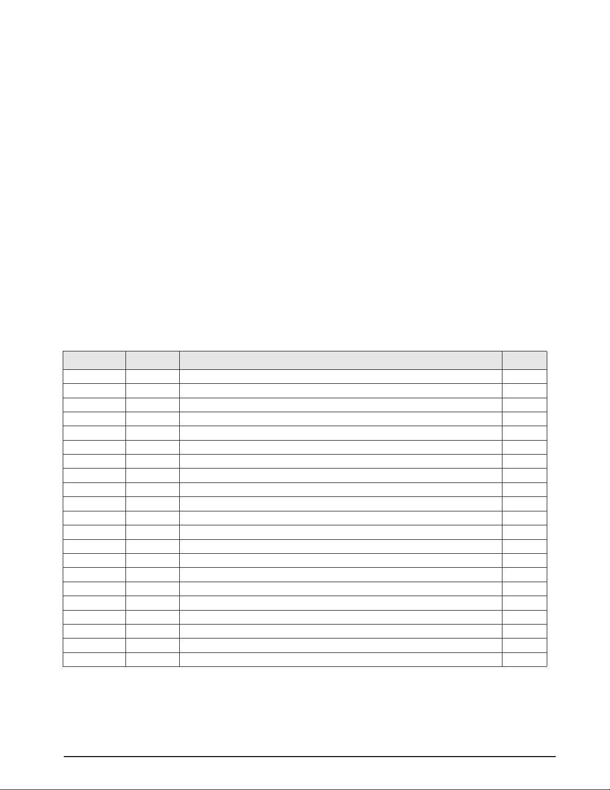
3.3 MPV Valve Assembly (PN 65076) Parts List
The following table lists the component parts of the MPV.
* Part must be ordered seperately.
Ref Number PN Description Quantity
1 54193
2 54540
3 59551
4 55896
5 59045
6 57889
7 55570
8 60837
9 60633
10 59387
11 57482
12 54401
13 60202
14 59245
15 58079
16 59322
17 59383
18 55569
19 55552
20 *59731
21 *59872
Valve body
Housing, valve needle
Valve needle
Valve, seat
Valve, needle seat
Knob Insert
Washer, backing
Screw, mach-pan HD
Retainer, packing
Valve seat, stem
Nut, valve needle housing
Locknut
Setscrew, hex housing
Washer, flat
*Knob
*Setscrew
Setscrew
O-ring, Fluorocarbon (Viton) color black w/white dot
O-ring, Fluorocarbon (Viton), color black w/white dot
Fitting, Male Connector 1/4 Tube
Fitting, Male Run Tee 1/4 Tube
1
1
1
1
1
1
1
1
1
1
1
1
1
1
1
2
2
1
1
1
1
Table 3-2. MPV Valve Assembly Parts List
Maintenance & Service 19
Page 24
20 PIN7000/PIN7010 Operation and Maintenance Manual
Page 25
3.4 Intensifier Assembly Parts List
Ref
Number
1 59328
2 60704
3 59548
4 55589
5 59333
6 59508
7 55579
8 60133
9 60343
10 57410
11 56714
12 57236
13 54456
14 55596
15 57114
16 59785
17 60333
18 59070
19 58786
20 60579
21 55600
22 54614
23 59794
24 58752
25 69435
PN Description Quantity
Screw, cap, socket
Washer, flat
Cap, end
O-ring, Buna-N (Nitrile) 70 Durometer color black
Screw, cap, socket head
Washer, flat
O-ring, Flourocarbon (Viton) 90 Durometer color black w/white dot
Housing, spring
Spring
Check valve
Seat, check valve
Fitting, check valve inlet
Retainer, packing backup
O-ring, Flourocarbon (Viton) 90 Durometer color black w/white dot
Seat, check valve
Adapter, High Pressure 1/4 NPT Male to Swagelok
Housing, piston
Piston
Cap, end
Retainer, packing
O-ring, Buna-N (Nitrile) 70 Durometer color black
Ring, piston
Elbow, 90 Tube to Male NPT
Retainer, piston ring
Dowel, round
10
10
1
1
10
10
1
1
2
2
1
1
1
1
1
1
1
1
1
2
1
3
1
1
1
Table 3-3. Intensifier Parts List
Maintenance & Service 21
Page 26
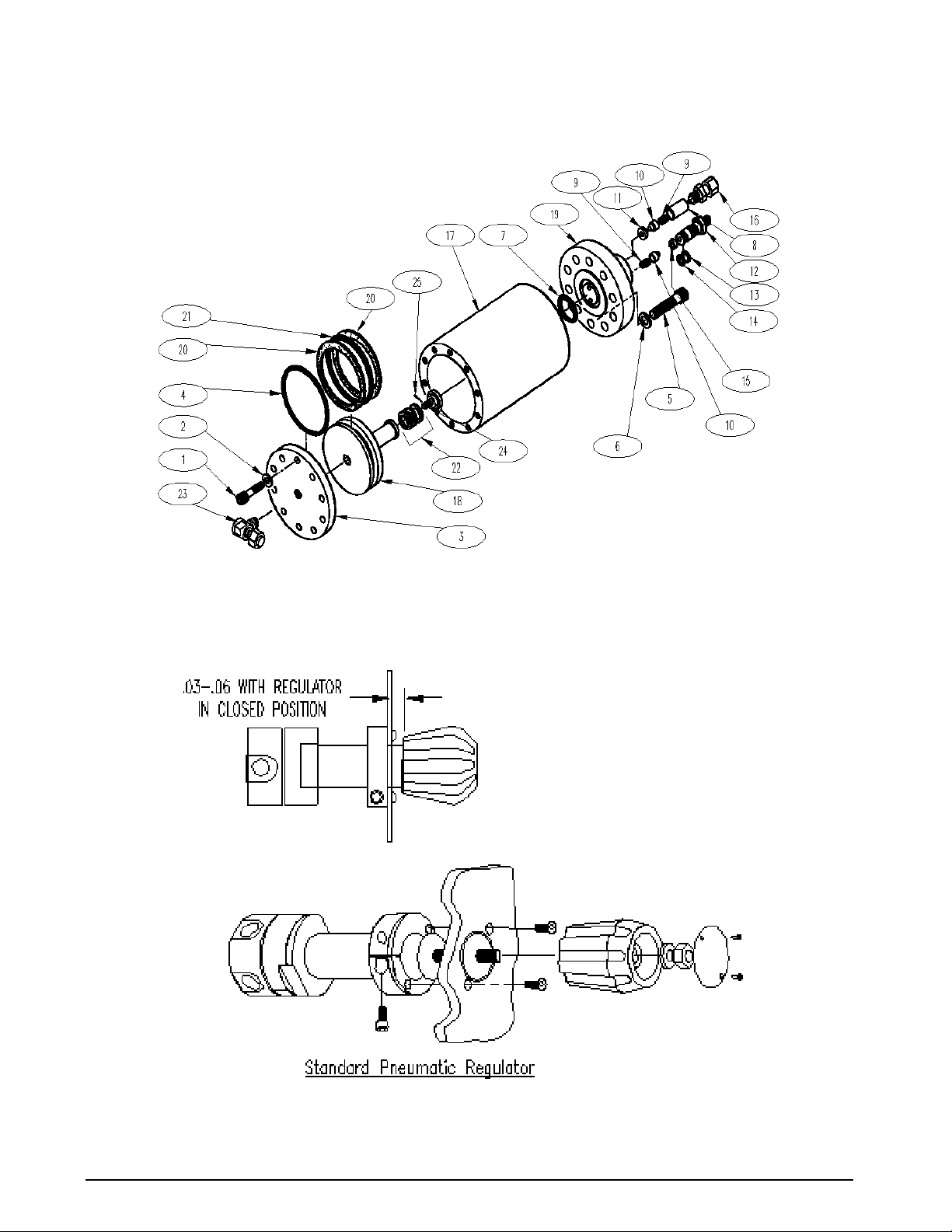
Figure 3-2. Intensifier Exploded View
Figure 3-3. Standard Pneumatic Regulator Mounting
22 PIN7000/PIN7010 Operation and Maintenance Manual
Page 27
Page 28
Page 29

4.0 Model Number System
P I N 7 0 0 0 - ____ ____
P I N 7 0 1 0 - ____ ____
¦ ¦
+-------------------------------------+ ¦
¦ POWER REQUIREMENTS ¦
¦ ¦
A - 120 VAC 50/60 Hz ¦
B - 220 VAC 50/60 Hz ¦
¦
+----------------------------------------------+
A - Standard
(Only applicable letter)
Model Number System 27
Page 30

5.0 Options, Replacement Kits
There are numerous replacement part numbers mentioned throughout manual that can be ordered.
MPV O-Ring Replacement Kit (Data Sheet # 65308):
• Fluorocarbon “Viton” (standard)...........................................................PN 55277
• Nitrile Buna-N.......................................................................................PN 58499
• Ethylene-Propylene...............................................................................PN 58506
• Silicone..................................................................................................PN 58509
• Neoprene ...............................................................................................PN 58515
NOTE: A small coating of Fluorinated Krytox grease, (PN 55593), should be applied to both sides of O-ring prior to
installation.
• Pressure Trap (Data Sheet # 58596)......................................................PN 58478
• Test Port (output) Quick-Disconnect Male Hose fitting.......................PN 55542
• Input Port Hose Nitrogen Bottle Mating fitting (one each of the following)
Cheat Seal Pad...................................PN 54854
Hose Adapter fitting..........................PN 60803
CGA-580 Nipple...............................PN 57150
CGA-580 Nut....................................PN 57154
NOTE: For Input Port Quick-Disconnect Female Hose fitting assembly instructions see Section 3.2.16 on page 17.
Test Port (output) Hose, with Quick-Disconnect Male fitting:
• 5' Long...................................................................................................PN 55280
Input Port Hose, with Nitrogen Bottle Mating fitting:
• 4' Long...................................................................................................PN 55360
• 10' Long.................................................................................................PN 55366
• 15' Long.................................................................................................PN 55369
• 20' Long.................................................................................................PN 55375
External Pressure Cylinder w/ Shut-off Valve, Rupture Disk and Carrying Handle...... PN 59533
28 PIN7000/PIN7010 Operation and Maintenance Manual
Page 31

6.0 Specifications
Operating Temp: +40° to +122°F (+4.4° to +50.0° C)
Storage Temperature: 0° to +185° F (–17.8° to +85°C)
Pressure Media: Dry gaseous nitrogen, standard
Optional External Pressure Cylinder:
Capacity: 83.3 ft3 N2 @ 2,216 PSIG
Volume: 960 in
Rating: 2,216 psig
Test Pressure: 3,694 psig
Material: Aluminum
Regulated Pressure Gauge:
Size: 2-1/2 in. diameter
Range: 0–3,000 PSIG
Test Pressure: 4,500 PSIG
Accumulator and Output Pressure Gauges:
Size: 2-1/2 in. diameter
Range: 0–15,000 PSIG
Test Pressure: 22,500 PSIG
Over-pressure Rupture Disk:
Rating: 3,000 PSIG, nominal
Type: Stainless steel outer case
Pressure Media Filter:
Rating: 20 microns, Test Port and Input Port
Type: Field replaceable
MPV Pressure and Vent Valves:
Type: Micro-metering with replaceable soft
Material: Aluminum knobs, black anodized
Internal Piping:
Tubing: 1/8 in. O.D., 0.035 in. wall thickness,
Couplings: Stainless Steel, Swagelok type
Input Port:
Style: 1/4" 37° AN flare male
Pressure Rating: 2216 PSIG connected
Material: 300 series Stainless Steel
3
40 microns, Test Port Hose
seat
All other parts 300 series stainless
steel
seamless Cu.
1/4 in. O.D., 0.035 and 0.065 in. wall
thickness, seamless 304 Stainless
Steel
Vent Port:
Style: 1/4" 37° AN male
Pressure Rating: 10,000 PSIG
Material: 300 series Stainless Steel
Pressure Hoses:
Quantity Supplied: Two; one input, one output
Length: 4 ft. nominal, input hose
5 ft. nominal, output hose
Style: Input hose - Nylon-lined core tube
with synthetic fiber braid and polyester
cover. Fitted with CGA-580 (Brass)
nipple fitting on one end and 1/4" 37°
female AN swivel pressure fitting on
opposite end.
Output hose - Nylon-lined core tube
with synthetic fiber braid and
polyurethane cover. Fitted with
quick-disconnect plug (St Stl) on one
end and 1/4" 37° female AN swivel
tube coupling on the other.
Regulator:
Type: Single stage, self-venting, non-bleed
Pressure Rating: 3,000 PSIG max. inlet
Carrying Case PIN7000 only:
Type: Aluminum case with latched cover and
handle
Material thickness: 0.090 in., nominal
Finish: Enamel paint, textured finish
Color: Gray
Control Panel:
Material: Aluminum (5052-H32)
Thickness: 0.125 in
PIN7000 Finish: Gray enamel paint with black
silkscreen nomeclature
PIN7010 Finish: Dark Tan enamel paint with black
silkscreen nomenclature
Physical Specifications:
Weight: 46 lbs including all hoses and cables
PIN7000 Case Dim’s: 11" wide x 18" long x 11.5" high
PIN7010 Case Dim’s: 19" wide x 8.1" deep x 10.5" high
(Case Dimensions excluding front handles).
Test P or t:
Pressure Rating: 10,000 PSIG.
Material: 300 series Stainless Steel
Specifications 29
Page 32

7.0 PIN7000/PIN7010 Warranty and Return Policy
If possible, please save original packing material which is specifically designed for the unit. Should it be
necessary to ship the unit back to the factory, a suitable shipping container must be used along with sufficient
packing material. Do not put a shipping label on the unit as a "suitable shipping container." Some units have been
severely damaged this way. This is a delicate, precision instrument. Any damage incurred because of poor
packaging procedures will ultimately result in added service charges and longer turn-around times.
Vent all pressure lines and the nitrogen cylinder, if applicable, to the atmosphere before
#AUTION
When factory service is required, send in only the unit for repair. Retain fittings, nitrogen cylinder, manuals, etc. at
your facility. However, if there is a problem with a particular part, send in that part with the unit.
If a unit is found to be defective, it may be returned to our repair facility at the following address:
CONDEC
3 SIMM LANE
DOOR D, UNIT 2A
NEWTOWN, CT 06470
ATTN: PRESSURE PRODUCTS/REPAIR LAB
Each unit's I.D. plate is stamped with a date code (week/year) prior to shipment. Our warranty is twelve (12)
months from that date code and includes repair and/or replacement of the unit at our, Newtown facilities at no
charge. Units subjected to abuse or damaged by external influences, are not covered under warranty.
If the unit is found to be out of warranty, an evaluation char ge of not less than fifty (U.S.) dollars ($50.00) will be
charged. Please note on any attached paperwork if a repair estimate is required or if there are any other specific
instructions.
Please be explicit as to the nature of the problem and/or its symptoms. Your documentation will save needless
time and expense. Also, please include a return shipping address (with a street address) and a contact name with
fax and telephone numbers. Contact numbers are necessary to provide a job estimate and in case further
questions arise at the factory.
shipping.
30 PIN7000/PIN7010 Operation and Maintenance Manual
Page 33
PIN7000/PIN7010 Return Material Authorization Form
The repair lab is also equipped to do calibrations on our calibrators and pressure standards. Calibrations include a
certification and are traceable to N.I.S.T.
COMPANY NAME:
STREET:
CITY, STATE, ZIP:
TE LE P HON E:
FAX:
CONTACT PERSON:
MODEL NUMBER: _______________ SERIAL NUMBER: ______________________________
PROBLEM WITH UNIT (PLEASE BE SPECIFIC):
IS THIS A WARRANTY REPAIR? ( ) YES ( ) NO
SHIP TO Address:
COMPANY NAME:
STREET:
CITY, STATE, ZIP:
ATTN:
CONDEC • 3 SIMM LANE • DOOR D, UNIT 2A • NEWTOWN, CT 06470
ATTN: PRESSURE PRODUCTS/REPAIR LAB
TEL: 888-295-8475 • FAX: 203-364-1556 or 715-234-6967
WEB SITE: www.4condec.com
PIN7000/PIN7010 Warranty and Return Policy 31
 Loading...