

Page 1
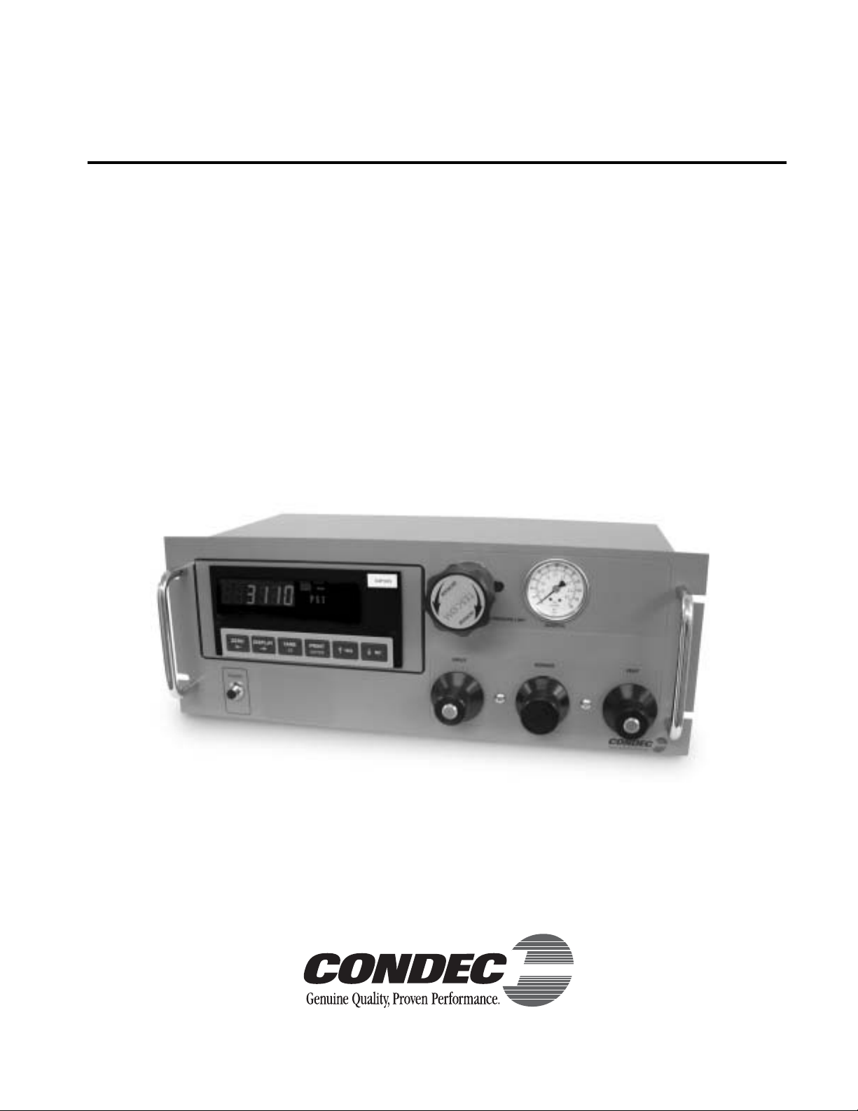
DLR3110
Rack-mountable Pneumatic
Pressure Calibration Console
Technical Manual
• Operation
• Calibration
• Maintenance
• Service
CONDEC Sales Phone No.: (888) 295-8475
CONDEC Web Site: WWW.4CONDEC.COM
74843
Page 2

Page 3

Contents
About This Manual................................................................................................................................... 1
1.0 Introduction.................................................................................................................................. 1
2.0 Installation and Wiring................................................................................................................ 3
2.1 Unpacking and Inspection . . . . . . . . . . . . . . . . . . . . . . . . . . . . . . . . . . . . . . . . . . . . . . . . . . . . . . . . . 3
2.2 Repacking . . . . . . . . . . . . . . . . . . . . . . . . . . . . . . . . . . . . . . . . . . . . . . . . . . . . . . . . . . . . . . . . . . . . . 3
2.3 Rear Panel Configuration . . . . . . . . . . . . . . . . . . . . . . . . . . . . . . . . . . . . . . . . . . . . . . . . . . . . . . . . . . 3
2.4 Hardware Configuration and Wiring . . . . . . . . . . . . . . . . . . . . . . . . . . . . . . . . . . . . . . . . . . . . . . . . . . 4
2.5 Display/Keyboard Functions . . . . . . . . . . . . . . . . . . . . . . . . . . . . . . . . . . . . . . . . . . . . . . . . . . . . . . . 4
2.6 Freeze Mode . . . . . . . . . . . . . . . . . . . . . . . . . . . . . . . . . . . . . . . . . . . . . . . . . . . . . . . . . . . . . . . . . . . 5
2.6.1 Freeze Mode Specifications . . . . . . . . . . . . . . . . . . . . . . . . . . . . . . . . . . . . . . . . . . . . . . . . . . . . . . . . . 6
2.7 Min and Max Mode . . . . . . . . . . . . . . . . . . . . . . . . . . . . . . . . . . . . . . . . . . . . . . . . . . . . . . . . . . . . . . 6
2.7.1 Resetting Min and Max Values . . . . . . . . . . . . . . . . . . . . . . . . . . . . . . . . . . . . . . . . . . . . . . . . . . . . . . . 6
2.8 Remote Display Mode . . . . . . . . . . . . . . . . . . . . . . . . . . . . . . . . . . . . . . . . . . . . . . . . . . . . . . . . . . . . 6
3.0 Operation...................................................................................................................................... 8
3.1 Initial Setup Procedure. . . . . . . . . . . . . . . . . . . . . . . . . . . . . . . . . . . . . . . . . . . . . . . . . . . . . . . . . . . . 8
3.2 Pressure Measurement Sequence (Gage) . . . . . . . . . . . . . . . . . . . . . . . . . . . . . . . . . . . . . . . . . . . . . 8
3.3 Pressure Measurement Sequence (Absolute). . . . . . . . . . . . . . . . . . . . . . . . . . . . . . . . . . . . . . . . . . . 8
4.0 Re-Calibration Only.................................................................................................................... 10
4.1 Pneumatic Calibration Set-Up . . . . . . . . . . . . . . . . . . . . . . . . . . . . . . . . . . . . . . . . . . . . . . . . . . . . . 10
4.2 Instrument Calibration Set-Up . . . . . . . . . . . . . . . . . . . . . . . . . . . . . . . . . . . . . . . . . . . . . . . . . . . . . 10
4.3 Re-Calibration Procedure (Zero, Linearity and Hysteresis) . . . . . . . . . . . . . . . . . . . . . . . . . . . . . . . . 10
5.0 Configuration and Calibration.................................................................................................... 12
5.1 Pneumatic Calibration Set-Up . . . . . . . . . . . . . . . . . . . . . . . . . . . . . . . . . . . . . . . . . . . . . . . . . . . . . 12
5.2 Instrument Calibration Set-Up . . . . . . . . . . . . . . . . . . . . . . . . . . . . . . . . . . . . . . . . . . . . . . . . . . . . . 12
5.3 Mode Selection Switch (S1) . . . . . . . . . . . . . . . . . . . . . . . . . . . . . . . . . . . . . . . . . . . . . . . . . . . . . . . 12
5.4 Main Set-Up Mode Menu Selections . . . . . . . . . . . . . . . . . . . . . . . . . . . . . . . . . . . . . . . . . . . . . . . . 13
5.5 Auto Set-Up Configuration Mode Selection . . . . . . . . . . . . . . . . . . . . . . . . . . . . . . . . . . . . . . . . . . . 14
5.5.1 Auto Set-Up Menu (General). . . . . . . . . . . . . . . . . . . . . . . . . . . . . . . . . . . . . . . . . . . . . . . . . . . . . . . . 14
5.5.2 Auto Set-Up Menu (Gage). . . . . . . . . . . . . . . . . . . . . . . . . . . . . . . . . . . . . . . . . . . . . . . . . . . . . . . . . . 15
5.5.3 Auto Set-Up Menu (Absolute) . . . . . . . . . . . . . . . . . . . . . . . . . . . . . . . . . . . . . . . . . . . . . . . . . . . . . . . 16
5.6 Calibration Set-Up Configuration Mode Selection . . . . . . . . . . . . . . . . . . . . . . . . . . . . . . . . . . . . . . 16
5.6.1 Calibration Mode Menu. . . . . . . . . . . . . . . . . . . . . . . . . . . . . . . . . . . . . . . . . . . . . . . . . . . . . . . . . . . . 17
5.7 Modifying Data . . . . . . . . . . . . . . . . . . . . . . . . . . . . . . . . . . . . . . . . . . . . . . . . . . . . . . . . . . . . . . . . 19
5.8 Span Calibration Points . . . . . . . . . . . . . . . . . . . . . . . . . . . . . . . . . . . . . . . . . . . . . . . . . . . . . . . . . . 19
5.9 Resetting Span Calibration Points . . . . . . . . . . . . . . . . . . . . . . . . . . . . . . . . . . . . . . . . . . . . . . . . . . 19
5.10 Overwriting Span Calibration Points and Hysteresis . . . . . . . . . . . . . . . . . . . . . . . . . . . . . . . . . . . . 19
5.11 Configuration Set-Up Mode Selection . . . . . . . . . . . . . . . . . . . . . . . . . . . . . . . . . . . . . . . . . . . . . . 21
5.12 Conversion Set-Up Mode Selection . . . . . . . . . . . . . . . . . . . . . . . . . . . . . . . . . . . . . . . . . . . . . . . . 22
5.13 I/O Set-Up Mode Selection . . . . . . . . . . . . . . . . . . . . . . . . . . . . . . . . . . . . . . . . . . . . . . . . . . . . . . 23
5.13.1 Port 1 Set-Up Menu . . . . . . . . . . . . . . . . . . . . . . . . . . . . . . . . . . . . . . . . . . . . . . . . . . . . . . . . . . . . . . 24
5.13.2 Port 1 Printer Menu. . . . . . . . . . . . . . . . . . . . . . . . . . . . . . . . . . . . . . . . . . . . . . . . . . . . . . . . . . . . . . . 25
5.13.3 Port 1 Duplex Menu . . . . . . . . . . . . . . . . . . . . . . . . . . . . . . . . . . . . . . . . . . . . . . . . . . . . . . . . . . . . . . 26
5.13.4 Port 1 RS485 Menu . . . . . . . . . . . . . . . . . . . . . . . . . . . . . . . . . . . . . . . . . . . . . . . . . . . . . . . . . . . . . . 28
5.13.5 Port 1 Simplex Menu . . . . . . . . . . . . . . . . . . . . . . . . . . . . . . . . . . . . . . . . . . . . . . . . . . . . . . . . . . . . . 28
5.13.6 Port 2 Set-Up. . . . . . . . . . . . . . . . . . . . . . . . . . . . . . . . . . . . . . . . . . . . . . . . . . . . . . . . . . . . . . . . . . . 29
5.13.7 Time and Date Set-Up Menu . . . . . . . . . . . . . . . . . . . . . . . . . . . . . . . . . . . . . . . . . . . . . . . . . . . . . . . 30
5.13.8 Input Set-Up. . . . . . . . . . . . . . . . . . . . . . . . . . . . . . . . . . . . . . . . . . . . . . . . . . . . . . . . . . . . . . . . . . . . 30
5.13.9 Print and Zero Wiring Configration Example . . . . . . . . . . . . . . . . . . . . . . . . . . . . . . . . . . . . . . . . . . . . 31
Copyright © 2002 Rice Lake Weighing Systems. All rights reserved. Printed in the United States of America.
Specifications subject to change without notice.
December 2002
Page 4

ii
6.0 Serial Input/Output..................................................................................................................... 32
6.1 ASCII - Data Formats. . . . . . . . . . . . . . . . . . . . . . . . . . . . . . . . . . . . . . . . . . . . . . . . . . . . . . . . . . . . 32
6.2 Printer (Port One or Port Two) . . . . . . . . . . . . . . . . . . . . . . . . . . . . . . . . . . . . . . . . . . . . . . . . . . . . . 33
6.3 Duplex (Port One Only) . . . . . . . . . . . . . . . . . . . . . . . . . . . . . . . . . . . . . . . . . . . . . . . . . . . . . . . . . . 33
6.3.1 Full Duplex Protocol . . . . . . . . . . . . . . . . . . . . . . . . . . . . . . . . . . . . . . . . . . . . . . . . . . . . . . . . . . . . . . 34
6.3.2 Command Code <cmd> Description . . . . . . . . . . . . . . . . . . . . . . . . . . . . . . . . . . . . . . . . . . . . . . . . . 34
6.3.3 Basic RS485 Commands . . . . . . . . . . . . . . . . . . . . . . . . . . . . . . . . . . . . . . . . . . . . . . . . . . . . . . . . . . 35
6.4 Continuous Simplex Output (Compressed Format) . . . . . . . . . . . . . . . . . . . . . . . . . . . . . . . . . . . . . 35
6.5 Serial Output Wiring and Hardware Configuration . . . . . . . . . . . . . . . . . . . . . . . . . . . . . . . . . . . . . . 35
7.0 Maintenance and Service.......................................................................................................... 39
7.1 Troubleshooting . . . . . . . . . . . . . . . . . . . . . . . . . . . . . . . . . . . . . . . . . . . . . . . . . . . . . . . . . . . . . . . 39
7.2 Maintenance and Service Procedures . . . . . . . . . . . . . . . . . . . . . . . . . . . . . . . . . . . . . . . . . . . . . . . 39
7.2.1 Panel/Chassis Removal and Installation . . . . . . . . . . . . . . . . . . . . . . . . . . . . . . . . . . . . . . . . . . . . . . . 39
7.2.2 ORION-2C (PN 55283) or ORION-3A (PN 55287) Manifold Removal. . . . . . . . . . . . . . . . . . . . . . . . . . 40
7.2.3 ORION Manifold - Valve Seat Removal . . . . . . . . . . . . . . . . . . . . . . . . . . . . . . . . . . . . . . . . . . . . . . . . 40
7.2.4 ORION Manifold - Vernier Control Disassembly. . . . . . . . . . . . . . . . . . . . . . . . . . . . . . . . . . . . . . . . . . 41
7.2.5 ORION Manifold - Vernier Control Reassembly . . . . . . . . . . . . . . . . . . . . . . . . . . . . . . . . . . . . . . . . . . 42
7.2.6 ORION-2C Manifold - Valve Seat Installation. . . . . . . . . . . . . . . . . . . . . . . . . . . . . . . . . . . . . . . . . . . . 42
7.2.7 ORION Manifold - Panel Installation. . . . . . . . . . . . . . . . . . . . . . . . . . . . . . . . . . . . . . . . . . . . . . . . . . . 43
7.2.8 ORION-2C Manifold - Valve Adjustment Procedure. . . . . . . . . . . . . . . . . . . . . . . . . . . . . . . . . . . . . . . 44
7.2.9 ORION-3A Manifold - Valve Adjustment Procedure . . . . . . . . . . . . . . . . . . . . . . . . . . . . . . . . . . . . . . 45
7.2.10 Pressure Limit Control (Standard Pneumatic), Regulator Removal. . . . . . . . . . . . . . . . . . . . . . . . . . . . 46
7.2.11 Pressure Limit Control (Standard Pneumatic), Regulator Installation . . . . . . . . . . . . . . . . . . . . . . . . . . 46
7.2.12 Pressure Limit Control (Tescom), Regulator Removal . . . . . . . . . . . . . . . . . . . . . . . . . . . . . . . . . . . . . 47
7.2.13 Pressure Limit Control (Tescom), Regulator Installation. . . . . . . . . . . . . . . . . . . . . . . . . . . . . . . . . . . . 47
7.2.14 Panel Gauge Removal. . . . . . . . . . . . . . . . . . . . . . . . . . . . . . . . . . . . . . . . . . . . . . . . . . . . . . . . . . . . . 48
7.2.15 Panel Gauge Installation . . . . . . . . . . . . . . . . . . . . . . . . . . . . . . . . . . . . . . . . . . . . . . . . . . . . . . . . . . . 48
7.2.16 Test Port Quick-Connect Fitting (PN 59762) Removal and Installation - 3 and 100 Full Scale PSI . . . . 48
7.2.17 Test Port Filter (PN 54188) Removal and Installation - 250 and 2500 Full Scale PSI . . . . . . . . . . . . . . 49
7.2.18 Test Port Quick-Connect Fitting (PN 59004) and Filter (PN 54188) Removal and Installation - 5000 and
7.2.19 Test Port (Output) Hose Quick-Connect Fitting and Filter Removal and Installation (PN 56991)- 5000 and
7.2.20 Input Port Filter (PN 54188) Removal and Installation - 2500 Full Scale PSI. . . . . . . . . . . . . . . . . . . . . 50
7.2.21 AC Fuse (PN 58076) - Removal and Installation . . . . . . . . . . . . . . . . . . . . . . . . . . . . . . . . . . . . . . . . . 51
7.2.22 Input Port Filter (PN 54188) Removal and Installation - 5000 and 10000 Full Scale PSI. . . . . . . . . . . . 51
7.2.23 AC Fuse (PN 58076) - Removal and Installation . . . . . . . . . . . . . . . . . . . . . . . . . . . . . . . . . . . . . . . . . 51
7.2.24 AC Power/EMI Line Filter (PN 58870) - Removal and Installation. . . . . . . . . . . . . . . . . . . . . . . . . . . . . 51
7.2.25 Power Switch (PN 58878) - Removal and Installation . . . . . . . . . . . . . . . . . . . . . . . . . . . . . . . . . . . . . 52
10000 Full Scale PSI . . . . . . . . . . . . . . . . . . . . . . . . . . . . . . . . . . . . . . . . . . . . . . . . . . . . . . . . . . . . . .49
10000 Full Scale PSI . . . . . . . . . . . . . . . . . . . . . . . . . . . . . . . . . . . . . . . . . . . . . . . . . . . . . . . . . . . . . .50
7.3 ORION-2C Valve Assembly Parts List . . . . . . . . . . . . . . . . . . . . . . . . . . . . . . . . . . . . . . . . . . . . . . . 53
7.4 ORION-3A Valve Assembly Parts List . . . . . . . . . . . . . . . . . . . . . . . . . . . . . . . . . . . . . . . . . . . . . . . 57
8.0 Model Numbering System......................................................................................................... 62
9.0 Auto Selection Default Tables ................................................................................................... 63
10.0 Conversion Factors.................................................................................................................... 66
11.0 Options, Replacement Kits ........................................................................................................ 67
12.0 Specifications............................................................................................................................ 68
DLR3110 Warranty and Return Policy.................................................................................................... 69
DLR3110 Return Material Authorization Form....................................................................................... 70
DLR3110 Rack Mount Digital Pressure Indicator Manual
Page 5

About This Manual
This manual is intended for use by service technicians
responsible for installing and servicing the DLR3110
Digital Pressure Calibrator.
The DLR3110 series rack-mount combines the DLR
Digital Pressure Calibrator with the Orion vernier for
calibration of a wide variety of pressure sensing and
measuring devices.
The DLR3110 utilizes a repeatable sensor coupled to
microprocessor-based electronic circuitry and a
selectable units conversion display system to provide
digital representation of measured pressure. The unit
has one test port. Dependent on model, a front panel
mounted gauge tells the operator system pressure and
includes a pressure regulator so the operator can not
over-pressure a unit under test. Test hose is supplied
standard for the customer. Front panel buttons provide
Warning
equipment. This is a high-pressure system. Only
personnel formally trained in the use of pneumatic
pressure equipment should be permitted to operate it.
Potentially dangerous conditions can be produced
through negligent handling or operation of the console
due to the high pressure used within the unit.
These units are strictly for use with pneumatic pressures.
Erroneous readings and potential damage could result
from the introduction of hydraulic fluids into the internal
tubing lines.
Before attempting to use either style
pressure calibrator, the following
instructions must be read and
understood by personnel using the
Authorized distributors and their
employees can view or download this
manual from the Condec distributor site
at
www.4condec.com
.
selection of the desired functions, including zeroing
(GAGE models only).
1.0 Introduction
Using microprocessor technology, the rack-mountable DLR3110 instrument offers a combination of features,
performance, versatility and reliability not previously available in a single, rack-mount pressure calibration
instrument. Some of the features of the DLR3110 are listed below:
• Streamlined, multi-function keyboard.
• Selectable configurations, automatic set-up mode and multiple conversion units.
•Based on model, accuracy equal to or better than ±0.05%, ±0.1% or ±0.25% of indicated value from 20%
of full scale.
•Alpha-numeric display prompting provides the operator with functional status information during both
operation and calibration.
•A manually adjustable regulator (when applicable) allows the maximum system input pressure to be
adjusted to any desired value higher (typically 20 – 50%) than the full scale range of the device being
tested. This regulator helps protect the unit under test from being inadvertently over-pressurized.
•No manual alignment or potentiometer adjustments are required for system calibration. (50,000
displayed graduations; ten-point linearity compensation; automatic gain adjustment).
•Calibration integrity: Tamper-proof design. Once calibrated, numerous safeguards guarantee the
integrity of pressure readings obtained.
•Operation: All controls, indicators and test port are accessible from the front panel. A version with test
port on rear of unit is available by special order. See Section 3.0 on page 8 for instructions on system
operation.
•For safe, clean operation, all pressure components are made of brass, copper, aluminum, or stainless steel
and proof-tested to at least 150% of maximum operating pressure. In addition, the system contains a
high-pressure burst disk and relief valves to protect both the operator and system components from harm
in the event of inadvertent over-pressurization.
The heart of this calibration system is a stable and repeatable pressure transducer. These sensors produce an
electrical output signal that is linearly proportional to the applied pressure.
Introduction
1
Page 6
2
By combining these sensors with microprocessor-based circuitry, an even higher degree of operational accuracy
and precision has been accomplished. For example, computer-generated correction curves for both the
non-linearity and the hysteresis of the sensors improve these characteristics by an order of magnitude or more.
Two micro-metering valves and vernier are provided to control the external nitrogen source while the digital
display indicates the magnitude of the applied test pressure. Also, a push-button switch provides the “zeroing” of
the pressure display (on GAGE models). Over-pressure protection, based on model, is provided via a fully
adjustable pressure regulator which is manually set for each new device being tested.
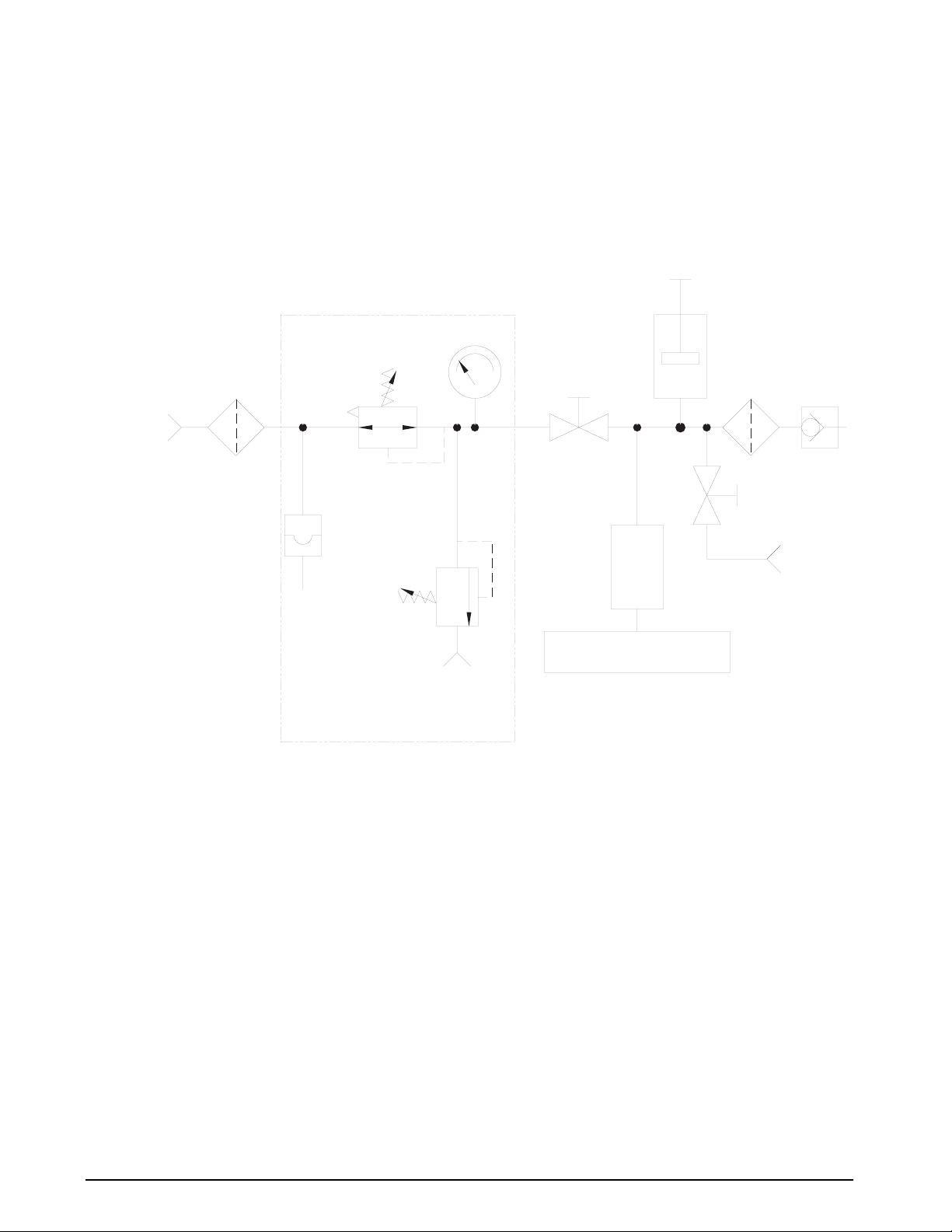
Figure 1-1 provides an overview of the DLR3110’s function.
VERNIER
ADJUST
PRESSURE LIMIT
MONITOR
FILTER
20u
INPUT PORT
NOTE: MAX INPUT BASED\P ON MODEL.
PRESSURE LIMIT
CONTROL
BURST DISK
3000 PSI
±50 PSI
RELIEF
VALVE
NOT REQUIRED ON 5K OR 10K MODELS
Figure 1-1. DLR3110 Flow Diagram
PRESSURE
INCREASE
MICROPROCESSOR-BASED
DIGITAL INDICATOR
DLR3110 FLOW DIAGRAM
FILTER
TEST PORT20u
(QUICK DISCONNECT)
VENT
VENT/VACUUM
PORT
TRANSDUCER
DLR3110 Rack Mount Digital Pressure Calibrator Manual
Page 7
2.0 Installation and Wiring
2.1 Unpacking and Inspection
Carefully remove the instrument from its shipping container. A visual inspection of the instrument's external
surfaces should be performed immediately after unpacking. If obvious damage occurred during transit, notify the
shipping agency and distributor as soon as possible to receive instructions on how to proceed after an assessment
of the damage is completed.
If the instrument shows no signs of damage, check to be sure all the required equipment and accessories were
included. Keep original shipping carton for repacking in case repair is necessary.
2.2 Repacking
If the DLR3110 must be returned for repair, recalibration, or modification, be sure that it is properly cushioned
and packed and that a description of the work to be performed is included. The original shipping carton should be
kept for this purpose.
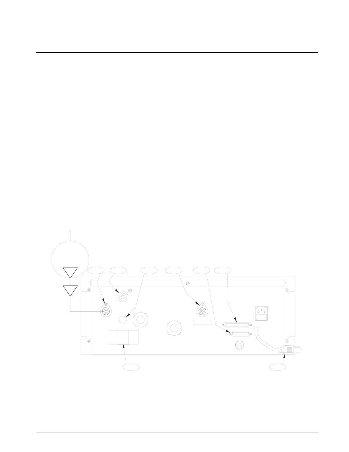
2.3 Rear Panel Configuration
The rear panel of the rack mount DLR3110 Series, contains the following items:
• AC power cord (1) and input receptacle.
• 7/16-20, 37
NOTE: The maximum input pressure, supplied by user, is noted below input pressure port.
• The unit's identification plate (4) and J6, 25 pin D connector, (5) for serial I/O communication interface.
•Optional if required items: Connector J5, 37 pin D connector, (6) for the Parallel BCD output. Connector
J2 (7) for the Freeze mode cable. Test port (8) in place of front mounted.
°
-4 AN male fittings, vent/vacuum port (2) and input pressure port (3).
VACUUM
PUMP
2 5
TEST PORT
J2
FREEZE MODE
VENT/VACUUM
PORT
4
78
J3
3
J1
INPUT
MAX. XXX
REAR VIEW
Figure 2-1. DLR3110 Rear View
6
AC INPUT
J5
J6
FUSE
1
Installation and Wiring
3
Page 8
4
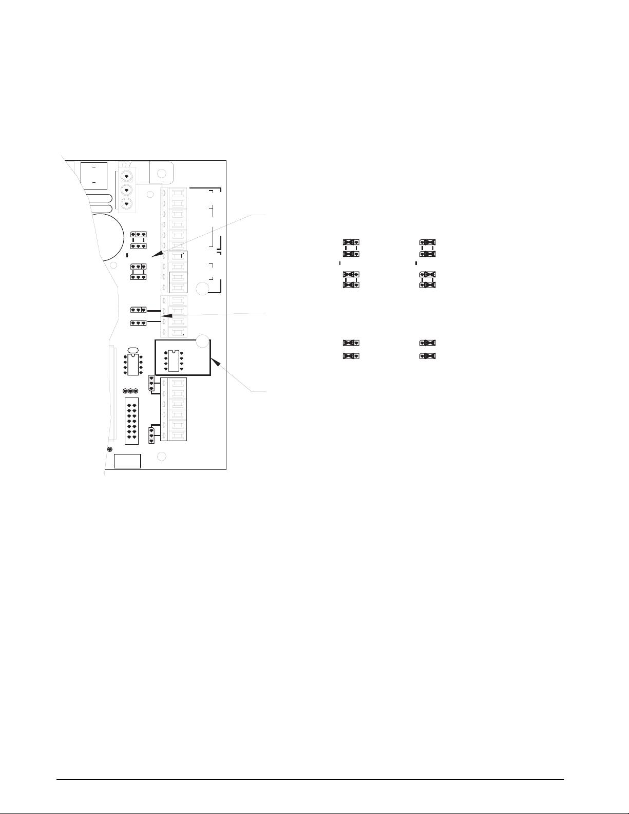
2.4 Hardware Configuration and Wiring
The CPU board in the DLR series has been designed for easy access to wiring and configuration of all available
inputs and outputs. In addition to easy access, the wire and configuration mapping provide clear labeling of all
input and output signals and the associated configurations of their device drivers.
J2
GND
LO
HI
S9
S8
S7
S6
S5
S4
C38
E11
E12
REMOTE SENSING
7
1
J3
+EXC
TB3
OUT
TB2
U18
10
RS485
AB
RS422
BA
1
3
1
S3
S2
20mA LOOP
P2
-OUT
+OUT
-IN
P1
+IN
-OUT
+OUT
SIG COM
IN
OUT
OUTOUT
+5V
I/O 2
I/O 1
RETURN
S10
P1 IN
RS232
OFF
20mA
RS485
RS422
6
-EXC
-SENSE
-SIG
+SIG
+SENSE
+EXC
1
CPU
TB1
TB1
ASSEMBLY
KKR8924-[]
DATE []
REV []
PORT 1 CONFIGURED FOR 20ma
CURRENT LOOP
RS232
P1
PORT 1 CONFIGURED FOR RS232
P2
SHOWN CONFIGURED AS INPUTS
SERIAL INPUT/OUTPUT SELECTION
JUMPER POSITION
P1
20mA
RS232
S9
S8
S7
S6
RS485
RS422
JUMPER POSITION
BA
AB
P1
20mA
RS232
RS485
S9
AB
PORT 1 CONFIGURED FOR RS485 OR
RS422 (TRANSMITTER)
S8
RS422
S7
PORT 1 CONFIGURED FOR RS485 OR
BA
RS422 (RECEIVER)
S6
INPUT/OUTPUT CONFIGURA TION
JUMPER POSITION
INS5OUT
S4
JUMPER POSITION
INS5OUT
S4
SHOWN CONFIGURED AS OUTPUTS
PORT 1 SERIAL INPUT SELECTION
THE PORT 1 INPUT SWITCH SELECTS FROM WHICH DEVICE THE SERIAL DATA IS RECEIVED
F1
C2
C1
3
20mA
P1
RS232
IN
E10
14
8
E8
S13
-EXC
Figure 2-2. CPU Configuration
NOTE: Unit is shipped previously set up and configured. For information on changing hardware configuration see
Section 5.11 on page 21.
2.5 Display/Keyboard Functions
See Figure 2-3 on page 5 for information on display and keyboard functions.
• Six-digit LED display of the measured pressure (1).
• Three annuciators: Two of the LEDs are used for indicating whether the unit is operating as a GAGE
pressure unit or as an absolute (ABS) pressure unit. The LED marked
delta P display mode (2).
• Eight character LED display for indicating the conversion units that the pressure data is currently being
displayed in. This display also scrolls prompting messages if corrective action is required or a problem
occurred in performing an operation (3).
For example, if attempting to perform a push to ZERO while the pressure data is in motion, the display
shows
Unit is in MOTION
• In GAGE units, the
.
function key (4) allows the indicator to be zeroed if it is within the limits
ZERO
defined by the ZERO configuration.
•
DISPLAY
key (5). In the normal operating mode this key is used to select and vie w all acti v e displays that
were enabled in the Configuration mode (i.e., Pressure data, MIN/MAX data, Freeze mode data, and
delta P display mode data).
indicates that the unit is in the
P
DLR3110 Rack Mount Digital Pressure Calibrator Manual
Page 9
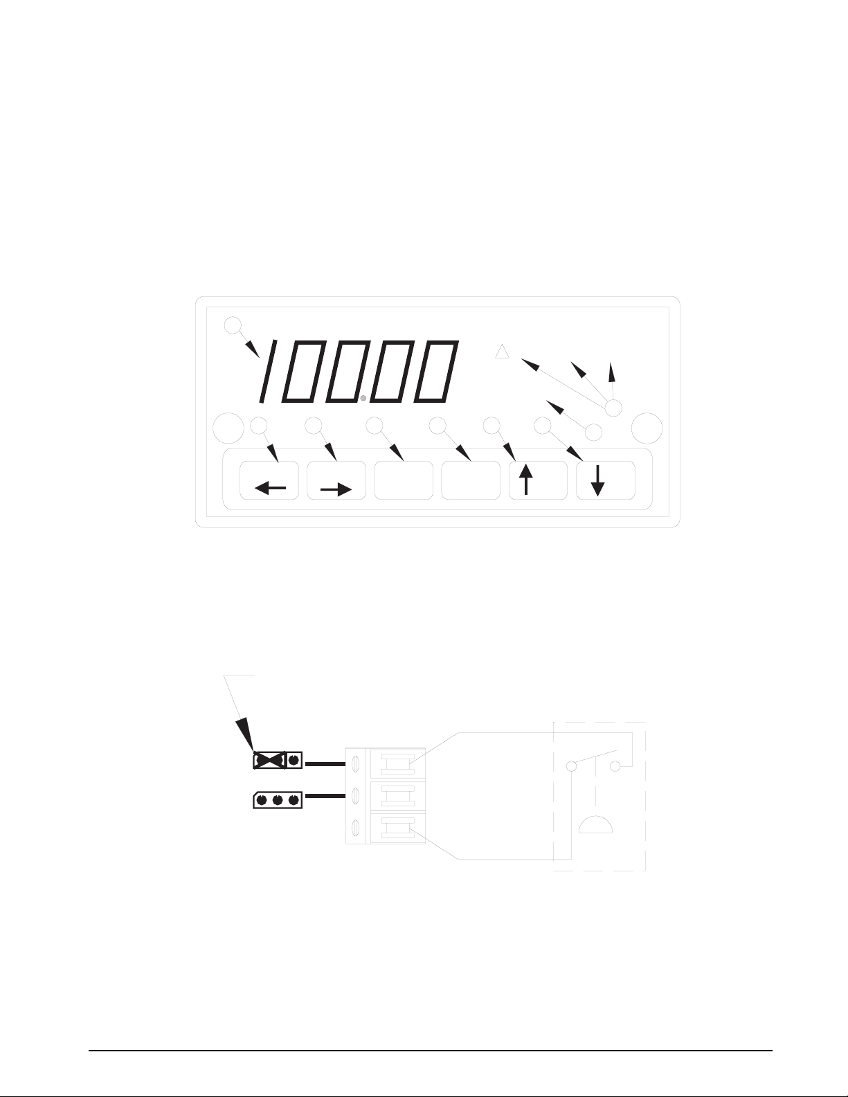
TARE
•
function key (6). The AUTO TARE (Auto.tr) feature is enabled in the Configuration mode under
the ZERO SET selection. When AUTO TARE is enabled, pressing the
TARE
key automatically tares out
the value of the current pressure display reading and shifts the display to the P (delta P) mode. The
resultant ZERO reference reading is useful in cases where it is desirable to subtract the atmospheric
pressure from an absolute reading to obtain a quick gauge reference.
NOTE: This pseudo-gage reading is only valid for the current atmospheric pressure that was tared out. Any
subsequent changes in atmospheric pressure result in an error.
PRINT
•
•
key (7) issues a demand serial printout of the display data from the indicator.
UP
(8) and
DOWN
(9) arrow keys step through and display the data in the conversion units that were
selected in the Configuration mode.
1
P Gage Abs
PSI
2
54
6
7
8 9
3
ZERO
DISPLAY
TARE
CE ENTER
PRINT
YES
NO
Figure 2-3. Display/Keyboard Functions
2.6 Freeze Mode
Freeze mode, used for testing pressure switches, is an edge triggered input signal that freezes the last display
update for the number of seconds (1 – 10 seconds) selected in the Configuration mode. The Freeze mode is
enabled in the CONFIG ?
Freeze mode).
menu under freeze time selections (Refer to Section 5.11 on page 21 for enabling the
JUMPER PLUG SHOWN ON S5 CONFIGURED AS AN INPUT
PRESSURE SWITCH
(+5 VDC)
S5
I/O 2
IN
S4
OUT
TB2
I/O 1
RETURN
(DIGITAL COMMON)
Figure 2-4. Freeze Mode CPU Connections
Either opening or closing of a switch contact between an active input (I/O 1 or I/O 2) and RETURN “freezes”
the
display (for the pre-selected amount of time in seconds) as shown above. However, while the display is in the
freeze condition, it does not respond to another contact transition
.
Installation and Wiring
5
Page 10
6
2.6.1 Freeze Mode Specifications
The following bullet points outline general specifications for the DLR3110’s Freeze mode.
• The freeze input “freezes”
the display for approximately five seconds on the rise and fall time of the
input (edge not level triggered) and can not be re-triggered.
• Input pulse > 100 ms required to guarantee detection.
• Freeze mode “freezes”
the 6 digit numeric and LED bar displays in whatever mode it is in (for example,
Normal, Net, Min and Max mode).
•Alphanumeric display prompts
•During the “freeze”
the front panel keys are inactive.
• Inputs are a +5 VDC logic level. Sinking current approximately
FREEZE
.
0.5 mA.
2.7 Min and Max Mode
The Min and Max mode is designed to capture and store the highest and the lowest pressure readings. These
values may be recalled at anytime in the normal operating mode by repeatedly pressing the
DISPLAY
the desired value is displayed. When either the minimum or maximum value is selected, the alphanumeric
display flashes between the mode (Min and Max) and its units.
NOTE: The Min and Max mode pressure data is automatically converted to any of the active conversion units by
stepping through the conversion units using the UP or DOWN arrow keys.
Both the Min and Max mode are independent of each other and are enabled (turned ON) in the Configuration
mode (see Section 5.11 on page 21).
key until
2.7.1 Resetting Min and Max Values
To reset the stored minimum or maximum value:
1. Select the Min or Max display to be reset using the
key. One of the following messages appears on the alphanumeric
2. Press the
YES OR NO; RESET MIN? YES OR NO.
CE
3. At the display prompt shown above, press the
resetting the value.
NOTE: Min and Max data work with the standard pressure, not delta pressure data.
DISPLAY
key to reset the value or press the
YES
key.
display:
NO
RESET MAX?
key to abort
2.8 Remote Display Mode
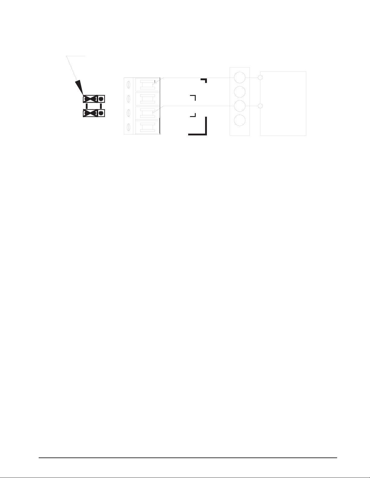
The following describes the setup for connecting the optional six-digit remote display (PN 74683). The display
duplicates the DLR3110 six-digit front panel display for all ranges and units selected (see Figure 2-5 on page 7).
NOTE: Remote display does not show current unit or mode designation.
See Table 5-10 on page 24 for setting the following parameters:
Parameter
Port 1 SIMPLEX
Baud 9600
Parity EVEN
Port 1 Modify
delay 1 AUTO
t –d 1 OFF
data 1 COMPRESS
EOL 1 CR
SOt 1 NONE
EOt 1 NONE
Configuration
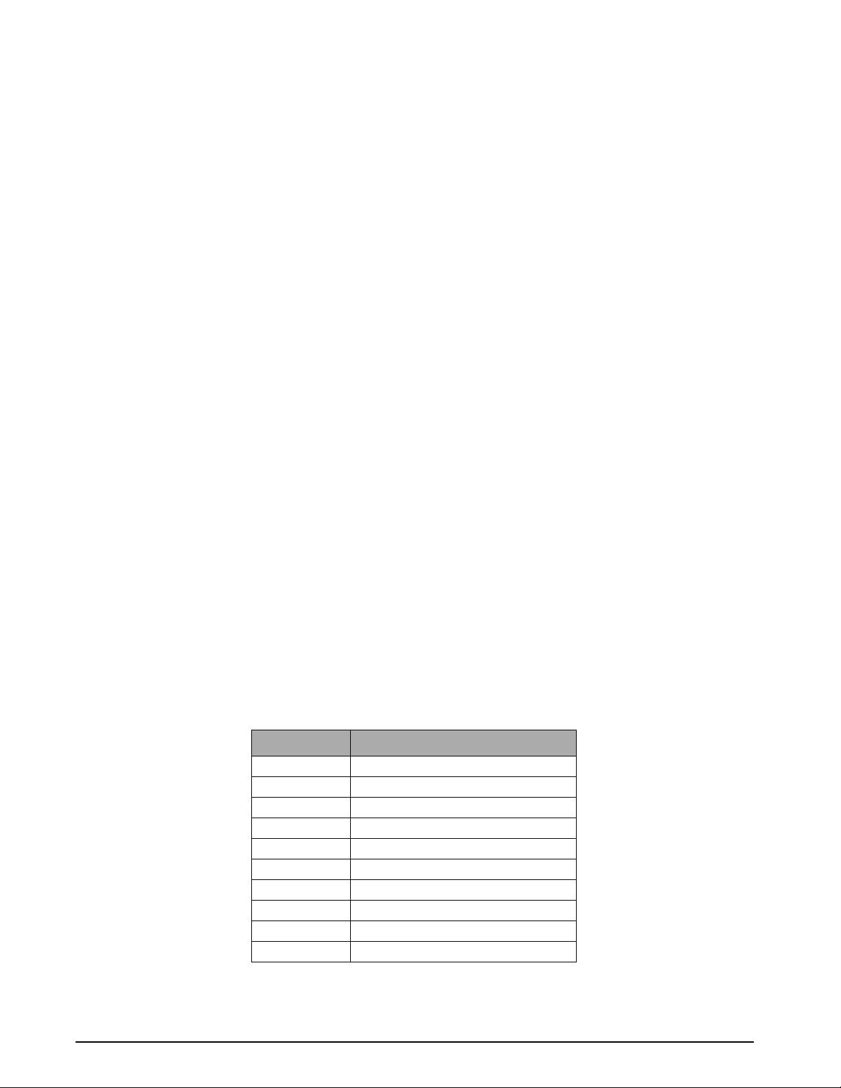
Table 2-1. DLR3110 Parameters
DLR3110 Rack Mount Digital Pressure Calibrator Manual
Page 11
JUMPER PLUGS SHOWN ON S6 & S7 CONFIGURED AS RS232
WIRE\PCOLOR
BLACK
P1
RS232
S7
S6
RS422
TB3
SIG COM
IN
BA
1
OUT
OUT
P1
P2
RS232
RED
Figure 2-5. DLR3110 CPU to Remote Display PN 74683 Wiring
J6
7
2
P2-4
ISO GND
P2-5
RS232 RXD
REMOTE DISPLAY
Installation and Wiring
7
Page 12

8
3.0 Operation
The following sections provide instructions on various operation procedures for the DLR3110.
3.1 Initial Setup Procedure
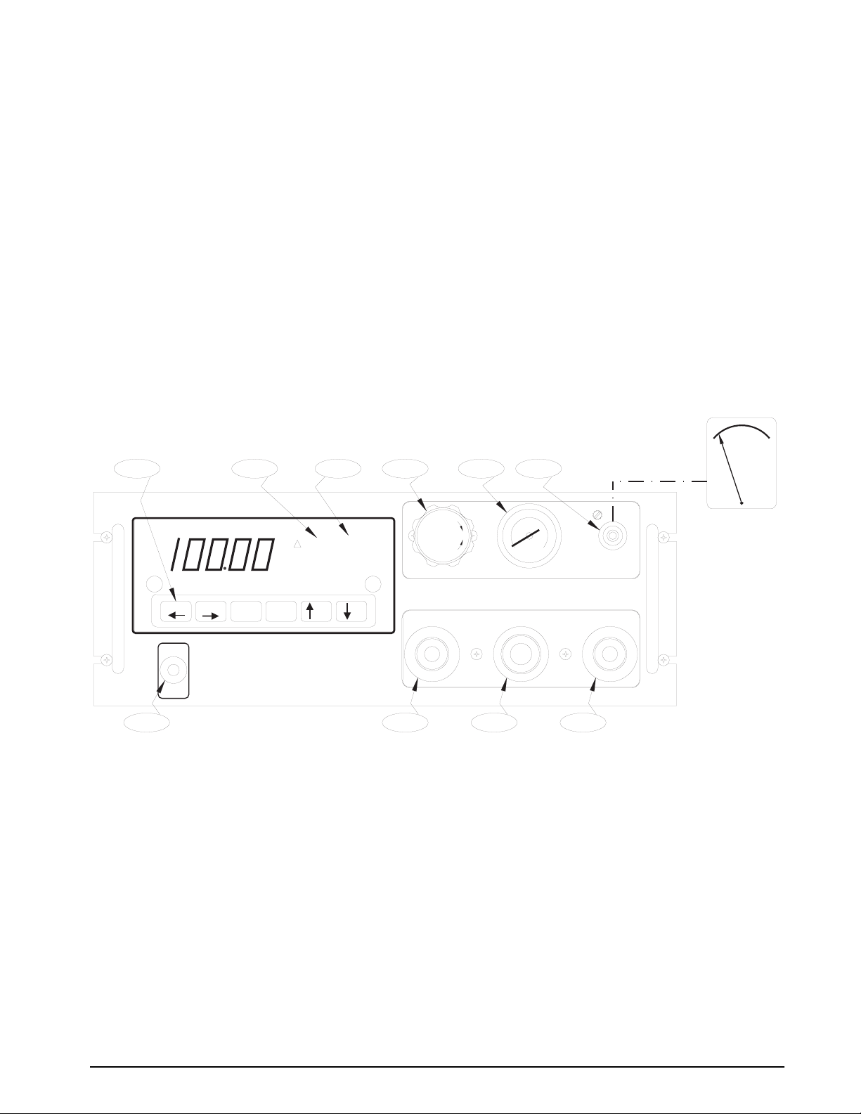
To prepare for actual calibration usage, see Figure 3-1 on page 9 and proceed as follows:
1. Check that the INPUT valve (1) is closed (rotate clockwise until it stops) and that the VENT valve (2) is
open (two turns counter-clockwise from its stop).
2. Plug in the power cord (see Section 2.3 on page 3) and power up the unit by pressing the power switch
(3). Allow at least 10 minutes warm-up time.
3. If applicable, use the PRESSURE LIMIT CONTROL REGULATOR (4) to adjust the maximum system
input pressure, as read by the PRESSURE LIMIT MONITOR (5), to any desired value higher (typically
20–50% higher) than the full-scale range of the Device-Under-Test (DUT). This procedure fully protects
the DUT from being accidentally over-pressurized.
4. Connect the male end of the test hose to the TEST PORT (6) fitting.
NOTE: DLR3110 may be ordered with Test port on rear of unit. See Section 2.3 on page 3.
5. Connect the swivel fitting end (7/16-20) of the test (output) hose to the DUT using adapters if required.
Tighten all connections properly.
3.2 Pressure Measurement Sequence (Gage)
Use the following steps to measure pressure with the GAGE model DLR3110:
1. With reference to Figure 3-1 on page 9, check that the indicator on the right end of the display indicates
Gage
(8). If not, see Section 5.11 on page 21.
switch (7). DLR3110’s LEDs momentarily display the word
2. Press and release the
the display returns to a
(2) is open, by momentarily depressing the
3. To apply pressure, close the VENT
the INPUT valve (1) approximately 1/2 turn counter-clockwise until the numerical display begins to
move. The pressure may change rapidly until reaching approximately 90% of the desired final value.
4. Use either the INPUT (1) or VENT valve (2) to obtain a specific pressure reading. Both provide precise
control. As the pressure approaches the desired value, the valve being used for control should be rotated
slowly clockwise to its closed position. With a little experience, pressure values very close to the desired
final value can be quickly achieved.
5. To obtain exact pressure readings, slowly rotate the VERNIER control knob (10) in the direction
required (clockwise to increase pressure) as indicated by the electronic numerical display.
ZERO
0
reading. The instrument may be zeroed at anytime, as long as the VENT valve
switch (7) for less than 5 seconds.
ZERO
valve (2) approximately two turns clockwise until it stops, then open
Zero
3.3 Pressure Measurement Sequence (Absolute)
Use the following steps to measure pressure with the ABSOLUTE model DLR3110:
1. With reference to Figure 3-1 on page 9, check that the indicator on the right end of the display indicates
Abs
(9). If not, see Section 5.11 on page 21.
2. If only pressure measurements greater than barometric are required, continue to step 2.1. If pressure
measurements above and below atmospheric pressure are required go to step 3.
a) To apply pressure, close the VENT valve (2) by turning clockwise approximately two times until it
stops and open the INPUT valve (1) by turning counter-clockwise approximately 1/2 turn until the
numerical display begins to move. In general, the pressure may be changed rapidly until reaching
approximately 90% of the desired final value.
b) Use either the INPUT (1) or VENT valve (2) to obtain a specific pressure reading. Both provide
precise control. As the pressure approaches the desired value, the valve being used for control should
be rotated slowly clockwise to its closed position. With a little experience, pressure values very close
to the desired final value may be quickly achieved.
c) To obtain exact pressure readings, slowly rotate the VERNIER control knob (10) in the direction
required (clockwise to increase pressure) as indicated by the electronic numerical display.
and then
DLR3110 Rack Mount Digital Pressure Calibrator Manual
Page 13
3. If pressure measurements above and below atmospheric pressure are required, connect a VACUUM
PUMP to the VACUUM/VENT port (2) as shown in Figure 2-1 on page 3.
4. Open the VENT valve (2), close the INPUT valve (1) and apply power to the vacuum pump and allow it
to evacuate the system for several minutes or until the digital display reading reaches equilibrium near
0 PSIA.
5. With the vacuum pump still running, close the VENT valve (2) and check for system leaks. If there are
none, continue to step 5.1.
a) To apply pressure, close the VENT valve (2) by turning clockwise approximately two turns to its
stop and open the INPUT valve (1) by turning counter-clockwise approximately 1/2 turn until the
numerical display begins to move. In general, the pressure may be changed rapidly until reaching
approximately 90% of it desired final value.
b) Use either the INPUT (1) or VENT valve (2) to obtain a specific pressure reading. Both provide
precise control. As the pressure approaches the desired value, the valve being used for control should
be rotated slowly clockwise to its closed position. With a little experience, pressure values very close
to the desired final value may be quickly achieved.
c) To obtain exact pressure readings, slowly rotate the VERNIER control (10) knob in the direction
required (clockwise to increase pressure) as indicated by the electronic numerical display.
7
DISPLAY
ZERO
POWER
89
P Gage Abs
PSI
PRINT
TARE
ENTER
CE
YES
NO
4
INCREASE
DECREASE
CONTROL
INPUT
1
56
PRESSURE LIMIT
MONITOR
VERNIER
DUT
TEST PORT
VENT
23 10
Figure 3-1. Pressure Measurement Sequence
Operation
9
Page 14

4.0 Re-Calibration Only
NOTE: This section is for the technician that is familiar with the front keyboard menus and is doing nothing more than a
re-calibration. The re-calibration must be done in the same base units as originally calibrated. For a more in-depth
configuration and calibration explanation, see Section 5.0 on page 12.
The step-by-step calibration sequence provided on the following pages permits a qualified technician to calibrate
an entire DLR3110 instrument in approximately 45 minutes.
The instrument has been designed and programmed to provide the operator with various prompting symbols and
legends during each phase of the calibration sequence. Also, to prevent unauthorized tampering or calibrations,
numerous features have been incorporated to minimize this potential danger.
However, it must be emphasized that when performing these tests, the computer within the DLR3110 is actually
being re-programmed and as such, it is imperative that the pressure standard being used is in satisfactory
operating condition and that the technician fully understands its operating characteristics and methods of usage.
In addition, the DLR3110 itself must be warmed up for approximately 30 minutes and electrically stabilized
prior to performing a calibration cycle.
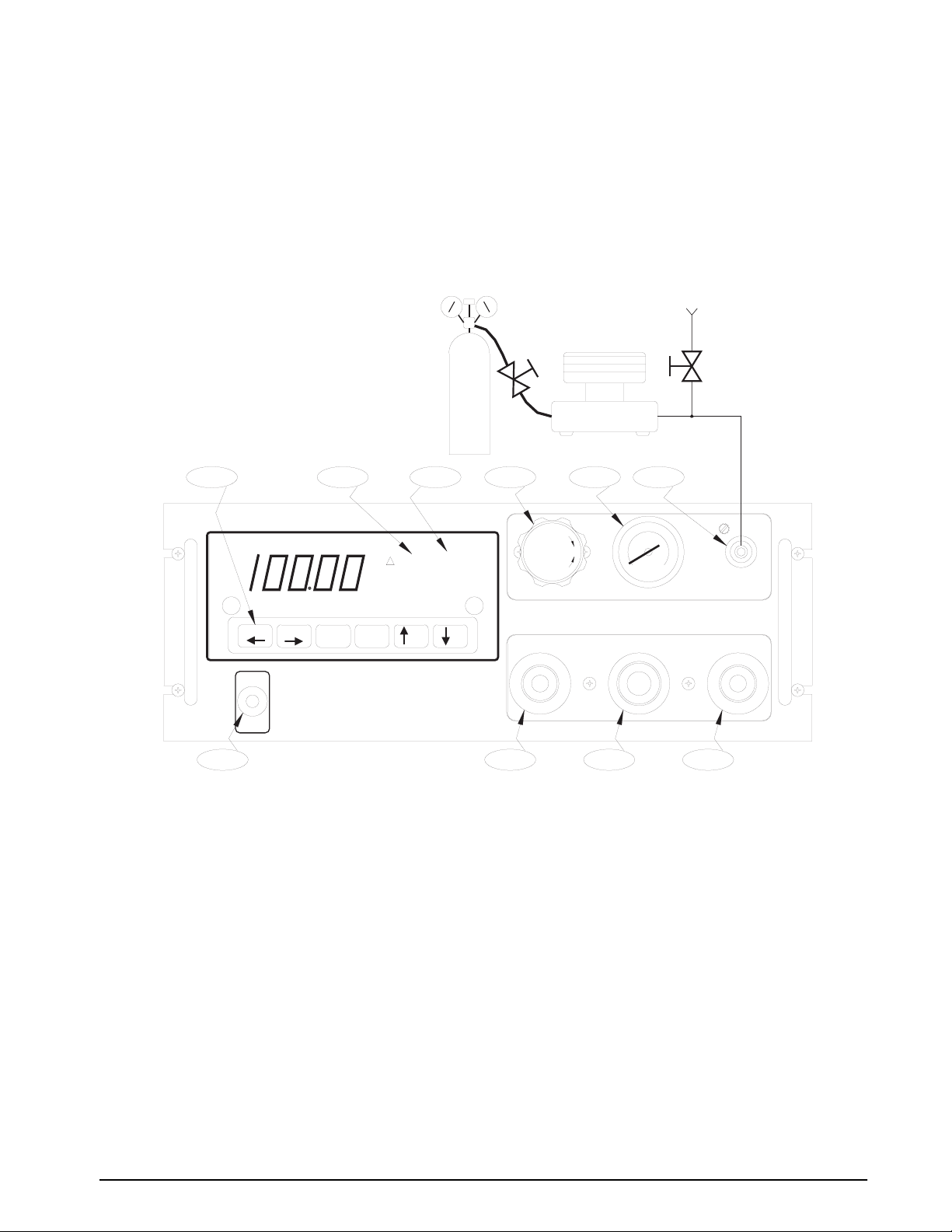
4.1 Pneumatic Calibration Set-Up
Figure 4-1 on page 11 defines a typical calibration set-up using a floating piston type dead weight tester.
However, any type of precision standard is acceptable as long as its basic accuracy is twice that of the
DLR3110’s or better.
To permit proper calibration at least an on/off and a vent valve must be provided (connected as shown in
Figure 4-1 on page 11).
10
4.2 Instrument Calibration Set-Up
Check that the INPUT valve (1) is closed (rotate clockwise until it stops) and that the VENT valve (2) is open
(two turns counter-clockwise from its stop).
The DLR3110 is placed into its Calibrate mode by closing rocker switch
the DLR3110's LED and alpha-numeric display is used to provide operator prompting symbols as well as
displaying the various data formats employed.
S1 position 2. In the Calibrate mode,
4.3 Re-Calibration Procedure (Zero, Linearity and Hysteresis)
Use the following steps for the re-calibration procedure of the DLR3110.
1. The alpha-numeric display reads
2. Press the
3. Press the
4. Press the
5. Press the
models and ABS for ABSOLUTE models. For GAGE models continue to step 6. For ABSOLUTE
models go to step 7.
6. Press the
INPUT valve is closed (rotate clockwise until it stops) and that the VENT valve is open (two turns
counter-clockwise from its stop).
Press the
Close the VENT valve (rotate clockwise until it stops). Go to step 7.
7. The alpha-numeric display reads
Set the input pressure from the test standard to the target value on the display. W ait for system to stabilize
and press the ENTER key on the display panel.
8. The alpha-numeric display reads
Set the input pressure from the test standard to the target value on the display. W ait for system to stabilize
and press the
target values.
DOWN arrow key on the display panel. The alpha-numeric display reads CAPACITY.
DOWN arrow key on the display panel. The display reads XXXX x .x.
DOWN arrow key on the display panel. The LED display reads base.
DOWN arrow key on the display panel. The alpha-numeric display reads GAGE for GAGE
DOWN arrow key on the display panel. The alpha-numeric display reads ZERO CAL. V erify the
ENTER key on the display panel. The LED display reads 0.00 (number of zeros arbitrary).
ENTER key on the display panel. Repeat this step for the next eight predetermined SPAN
FILTER X, where “X” represents a numerical variable.
SPAN 1 CAL TARGET=XXX, where “X” represents a numerical variable.
SPAN 2 CAL TARGET=XXX, where “X” represents a numerical variable.
DLR3110 Rack Mount Digital Pressure Calibrator Manual
Page 15
9. The alpha-numeric display reads HYST. CAL TARGET=XXX (X represents the preset target value on
display). Set the input pressure from the test standard to the target value on the display. Wait for system
to stabilize and press the ENTER key on the display panel.
NOTE: For ABS models, use a vacuum pump to reach the applicable SPAN or HYST target values that are
below local barometric pressure.
10. The alpha-numeric display reads FILTER 5. Save the calibration data by opening rocker switch S1
position 2. DLR3110 returns to normal mode.
11. Vent system and remove test standard.
"ON-OFF"
2-WAY VALVE
PNEUMATIC PRESSURE
TESTER
7
89
4
INCREASE
5
VENT
6
P Gage Abs
PSI
ZERO
POWER
DISPLAY
TARE
PRINT
YES
CE
ENTER
NO
3
DECREASE
CONTROL
INPUT
1
Figure 4-1. Instrument Calibration Set-Up
NOTE: AC input and input port are on back side rack-mountable calibrator.
PRESSURE LIMIT
10
MONITOR
VERNIER
TEST PORT
VENT
2
Re-Calibration Only 11
Page 16
5.0 Configuration and Calibration
The following sections cover configuration and calibration of the DLR3110. For information on calibrating the unit
without configuration changes, see Section 4.0 on page 10.
During the following procedures, the computer within the DLR3110 is actually being re-programmed. The pressure
standard being used during calibration should be in satisfactory condition and fully understood by the service
technician. In addition, the DLR3110 must be warmed up for approximately 30 minutes and electrically stabilized
prior to performing a calibration cycle.
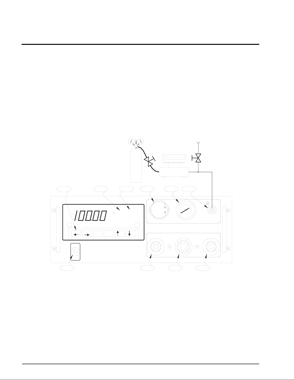
5.1 Pneumatic Calibration Set-Up
Figure 5-1 defines a typical calibration set-up using a floating piston type dead weight tester. Any precision
standard is acceptable to use providing its basic accuracy is at least twice that of the DLR3110’s.
5.2 Instrument Calibration Set-Up
Check that the INPUT valve (1) is closed (rotate clockwise until it stops) and that the VENT valve (2) is open
(two turns counter-clockwise from its stop).
"ON-OFF"
2-WAY VALVE
PNEUMATIC PRESSURE
TESTER
7
DISPLAY
ZERO
POWER
3
8
TARE
PRINT
CE
ENTER
9
P Gage Abs
PSI
YES
NO
4
INCREASE
DECREASE
CONTROL
INPUT
1
5
PRESSURE LIMIT
10
Figure 5-1. Instrument Calibration Set-up
NOTE: AC input and input port are on the back side of rack-mountable calibrator.
MONITOR
VERNIER
VENT
6
TEST PORT
VENT
2
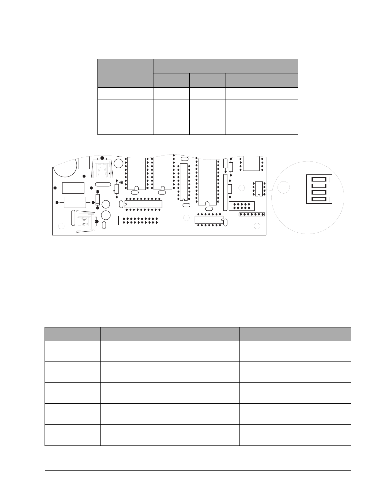
5.3 Mode Selection Switch (S1)
• Main set-up mode - Allows access to the Configuration and Calibration modes.
• Calibration mode - Accesses the Calibration mode directly.
• I/O mode - Allows direct access to the set up of the Serial I/O ports (ports 1 and 2), BCD, Analog output,
discrete inputs/outputs.
• Diagnostic mode - Accesses a diagnostic mode for troubleshooting and evaluation (f actory access only).
12 DLR3110 Rack Mount Digital Pressure Calibrator Manual
Page 17
Switch Position
Mode
1 2 3 4
Normal Closed Open Open Open
Main set-up Open Closed Open Open
Calibration Open Open Closed Open
Diagnostic Open Open Open Closed
Table 5-1. Mode Selection Switch Modes
1
+
+
C4
R4
R3
CR7
R2
C6
1
U1
C8
U2
C5
E15
C31
R20
C10
+
C22
C7
U14
+
11
1
J5
EXPANDER
C14
C20
U8
20
U7
10
C17
U6
C18
C37
U5
R6
DIAG
I/O
CAL
MAIN
R7
5
10
RP1
J1
U20
1
S1
MODE
6
J4
DISP
KEYBD
C35
DIAG
I/O
CAL
MAIN
OPEN
12 43
1
S1
MODE
FRONT OF DLR3110
Figure 5-2. Rocker Switch S1 Location
5.4 Main Set-Up Mode Menu Selections
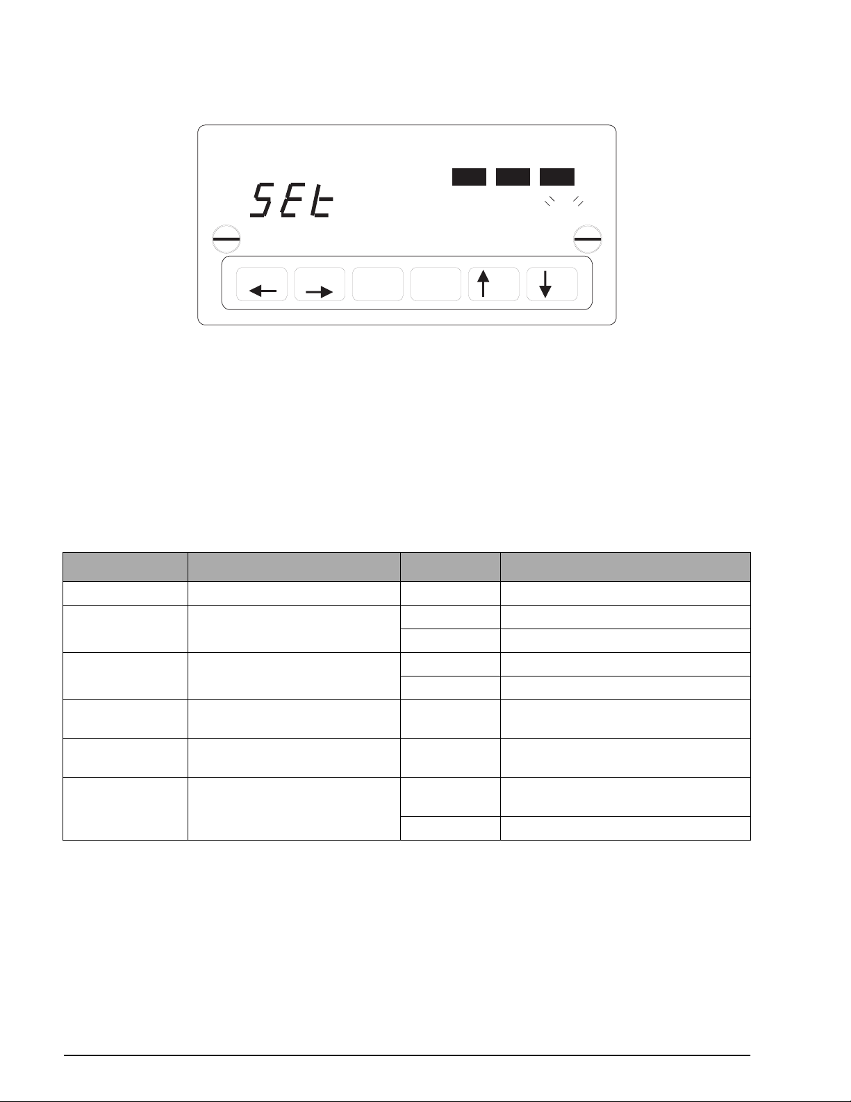
Enter the main setup mode by closing switch 1 of S1 located on the main board (see Section 5.3 on page 12). All
other switch positions on
Press
YES key to accept selections, NO key to reject.
LED Display Alpha-Numeric Display Key Pressed Remarks
SET AUTO ? YES key See Section 5.5 on page 14
SET-UP CONFIG ? YES key See Section 5.11 on page 21
---- CAL ? YES key See Section 5.6.1 on page 17
SET-UP I/O ? YES key See Table 5-10 on page 24
SET-UP CONV. ? YES key See Section 5.12 on page 22
S1 must be open. To save the changes and leave MAIN set-up, open switch 1 of S1.
NO key Continue to CONFIG?
NO key Continue to CAL?
NO key Continue to I/O?
NO key Continue to CONV?
NO key Return to AUTO?
Table 5-2. Main Set-Up Mode Selection Parameters
Configuration and Calibration 13
Page 18
AUTO ?
ZERO
DISPLAY
TARE
CE
PRINT
ENTER
YES
NO
Figure 5-3. Auto Set-Up Mode
5.5 Auto Set-Up Configuration Mode Selection
The auto set-up automatically sets the following conditions in the DLR3110:
•
SET-UP - CONFIG configuration parameters
•
SET-UP - CONV conversion parameters
•
SET-UP - I/O configuration of inputs/outputs
•
---- CAL sets capacity, count by, abs/gage, and cal units; resets all calibration values; sets all cal target
values for span and hysteresis.
5.5.1 Auto Set-Up Menu (General)
LED Display Alpha-Numeric Display Key Pressed* Remarks
SET AUTO ? YES key See Section 5.4 on page 13
---- GAGE ? YES key See Section 5.5.2 on page 15
NO key Continue to ---/ABS?
---- ABS ? YES key See Section 5.5.3 on page 16
NO key Continue to ---/SPECIAL?
---- SPECIAL. ? NO key Allocated for future use, continue to
----/CUSTOM ?
---- CUSTOM ? NO key Allocated for future use, continue to
----/EXIT ?
---- EXIT ? YES key Return to main set-up mode selections
(see Section 5.4 on page 13).
NO key Returns to ----/GAGE ?
Table 5-3. Auto Set-Up Mode Selection Parameters
* Press YES key to accept selection; NO key to reject.
Upon completion and accepting an AUTO set-up configuration, the program automatically advances the
indicator to the calibration mode (see Section 5.6.1 on page 17).
14 DLR3110 Rack Mount Digital Pressure Calibrator Manual
Page 19
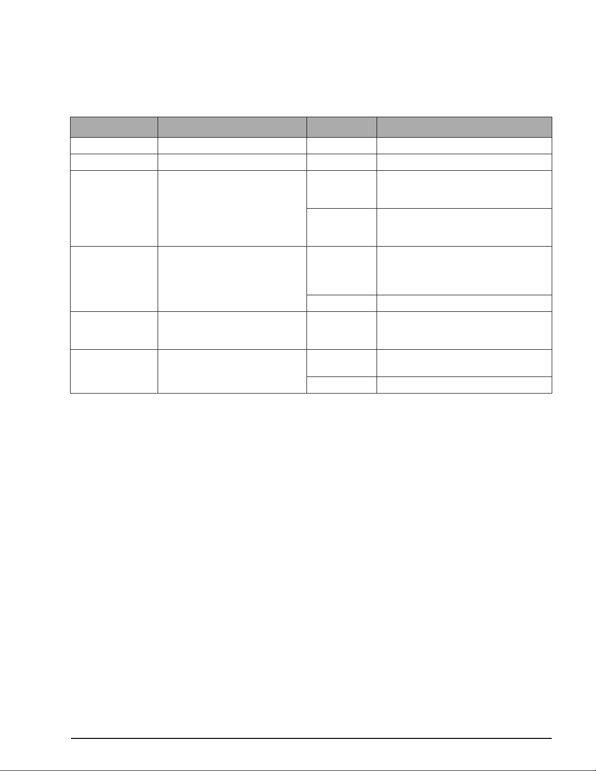
5.5.2 Auto Set-Up Menu (Gage)
See Section 9.0 on page 63 for a complete listing of the default settings for all gage and absolute selections under
the AUTO set-up mode.
LED Display Alpha-Numeric Display Key Pressed Remarks
SET AUTO ? YES key See Section 5.5 on page 14
---- GAGE ? YES key See Section 5.5 on page 14
SET-UP 3 PSIG ? NO key Continue to press NO key until the
alpha-numeric display shows the
DLR3110’s full scale range.
YES key Press YES key when the alpha-numeric
display shows the DLR3110’s full scale
range.
SET-UP ACCEPT ?
YES or NO.
XXXX CAPACITY YES key “XXX” shown on LED display represents
— EXIT ? YES key Return to SET-UP/ I/O?. (see Section 5.4
NO key Continue to press NO key until the
alpha-numeric display shows the
DLR3110’s full scale range. See note
below.
YES key Accept data
the full scale range and is based on
previous selection.
on page 13).
NO key Returns to XXX/CAPACITY
Table 5-4. Auto Set-Up Mode (Gage) Parameters Selections
NOTE: If you continue to press NO key past highest full scale range, DLR3110 will go to exit menu. Hit YES key at exit
menu (see Table 5-3 on page 14).
Configuration and Calibration 15
Page 20
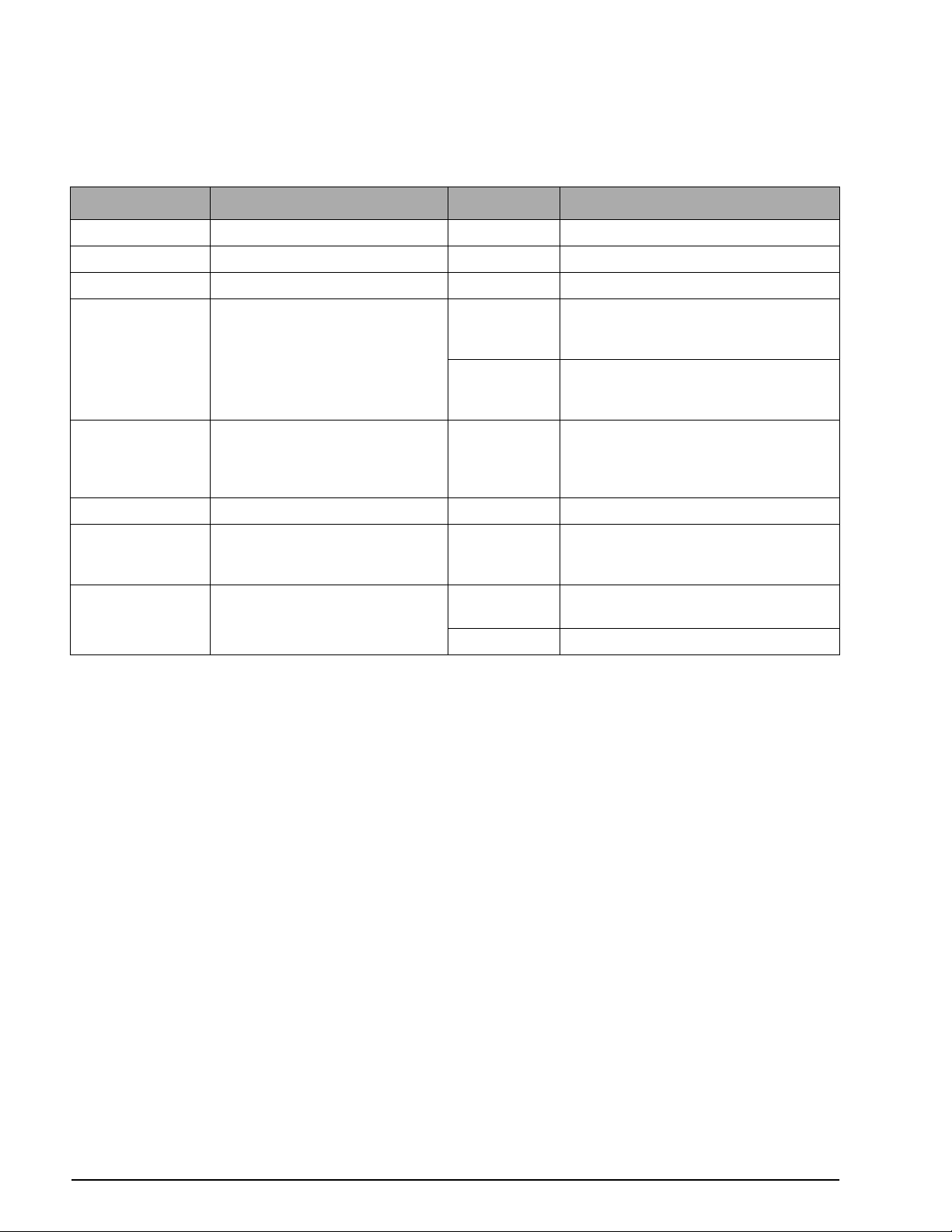
5.5.3 Auto Set-Up Menu (Absolute)
See Section 9.0 on page 63 for a complete listing of the default settings for all gage and absolute selections under
the AUTO set-up mode.
LED Display Alpha-Numeric Display Key Pressed Remarks
SET AUTO ? YES key See Section 5.5 on page 14
---- GAGE ? NO key See Section 5.5 on page 14
— ABS ? YES key See Section 5.5 on page 14
SET-UP 15 PSIA NO key Continue to press NO key until the
alpha-numberic display shows the
DLR3110’s full scale range.
YES key Press YES key when the alpha-numeric
display shows the DLR3110’s full scale
range.
SET-UP ACCEPT ?
YES or NO
——YES key Accept data
XXXX CAPACITY YES key “XXX” shown on LED display represents
— EXIT ? YES key Return to SET-UP/ I/O?. (see Section 5.4
NO key Continue to press NO key until the
alpha-numberic display shows the
DLR3110’s full scale range. See note
below.
the full scale range and is based on
previous selection.
on page 13).
NO key Return to XXX/CAPACITY
Table 5-5. Auto Set-Up Mode (Absolute) Parameters Selections
NOTE: If you continue to press NO key past highest full scale range, DLR3110 will go to exit menu. Hit YES key at exit
menu (see Table 5-3 on page 14).
5.6 Calibration Set-Up Configuration Mode Selection
Use one of the following methods for configuring the calibration set-up mode:
Method 1
CAL (SELECT). See Section 5.4 on page 13 for information on selecting main mode settings.
Method 2
CAL (DIRECT). Closing only rocker switch position
CALIBRATION mode. See Section 5.3 on page 12.
NOTE: If the AUTO SET-UP selection is accepted and completed, the indicator automatically advances to the calibration
mode (see Section 5.5 on page 14).
2 on switch S1 places the DLR3110 directly into
16 DLR3110 Rack Mount Digital Pressure Calibrator Manual
Page 21
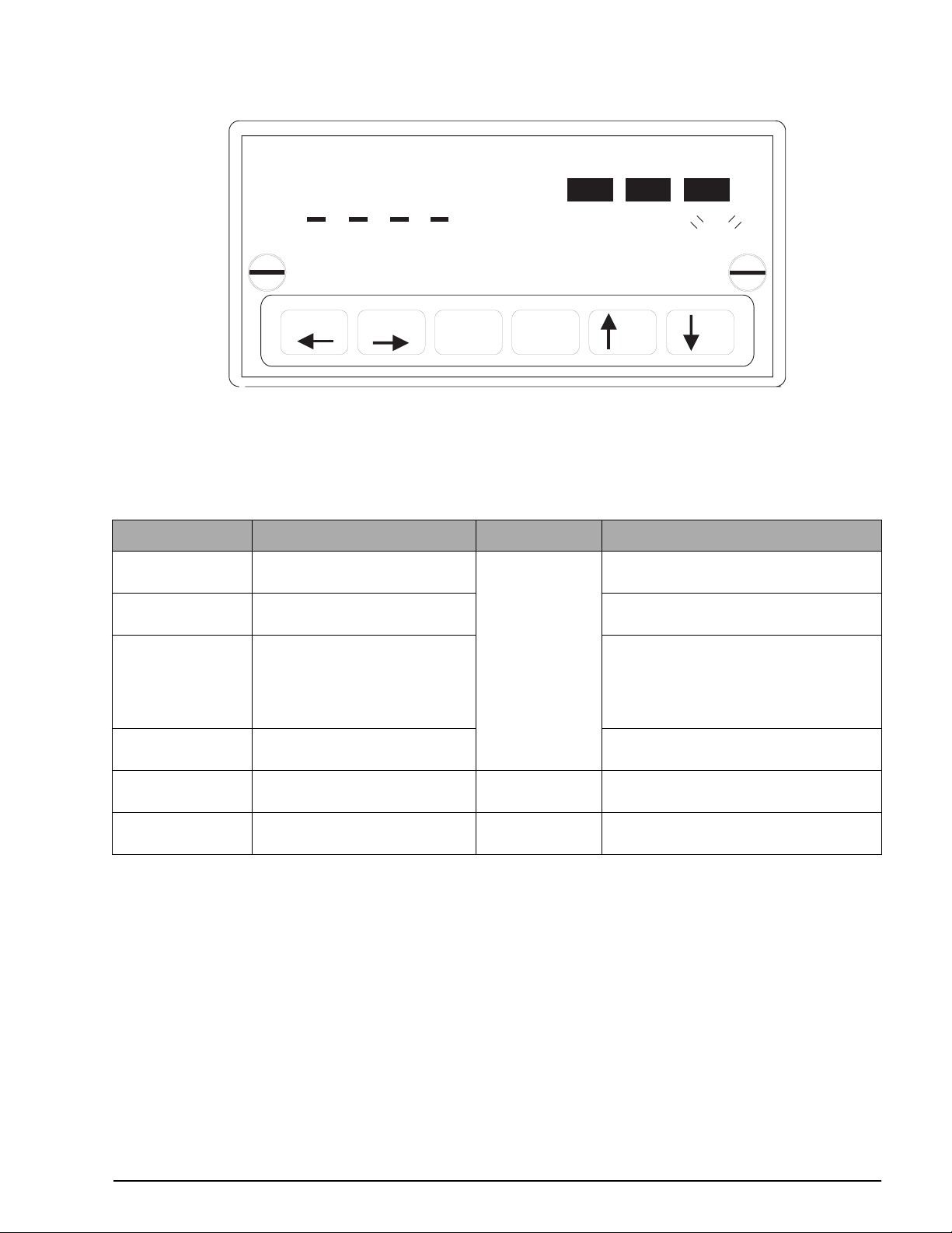
CAL ?
ZERO
DISPLAY
TARE PRINT
CE ENTER
YES
NO
Figure 5-4. Calibration Mode
5.6.1 Calibration Mode Menu
Press LEFT or RIGHT arrow keys to change values. The various menus may be exited or data selection aborted at
any time by pressing the
either the
YES or NO key is pressed.
LED Display Alpha-Numeric Display Key Pressed Remarks
**XXX CAPACITY DOWN arrow To change the capacity value, see
**XXX X .5 To change the resolution value, press LEFT
BASE PSI Press LEFT or RIGHT arrow key to select
---- GAGE ?
*XX ZERO CAL See step 1 below Does not exist on ABS type units. Disregard
*XX SPAN 1 TARGET VALUE=XX See step 3 below To change the target value, see Section 5.7
CE key. If the CE key is pressed, the prompt Exit ? YES or NO scrolls continuously until
Section 5.7 on page 19.
or RIGHT arrow key.
the base unit used to calibrate indicator. If
for any reason this selection is changed, the
indicator must be calibrated to the new
base unit selection.
Press LEFT or RIGHT arrow key to select
or ABS ?
choice.
steps 1 and 2 below on ABS units.
on page 19.
Table 5-6. Calibration Mode Parameter Selections
*XX represents existing data.
**XXX represents the present capacity of the DLR3110.
Use the following steps to set calibration data in the DLR3110 using the Calibration mode menu.
1. Verify that the INPUT valve (1) is closed (rotate clockwise until it stops) and that the VENT valve (2) is
open (two turns counter-clockwise from its stop). See Figure 5-1 on page 12.
2. Press the
ENTER key on the display panel keypad. The LED display reads 0.00. Close the VENT valve
(rotate clockwise until it stops).
NOTE: If ZERO is not accepted, display shows either SIGNAL INPUT UNDER MINIMUM ZERO RANGE or
INPUT ABOVE CAL INPUT RANGE (NO CAL messages).
3. Set the input pressure from the test standard to the target value on the display. W ait for system to stabilize
and press the ENTER key on the display panel.
NOTE: For pneumatic setup, see Section 5.1 on page 12. For absolute models, use a vacuum pump to reach
the applicable SPAN target values that are below local barometric pressure.
Configuration and Calibration 17
Page 22
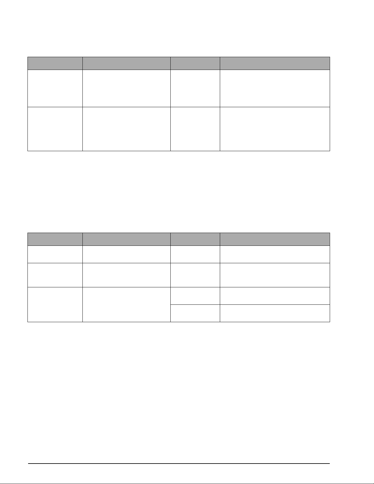
LED Display Alpha-Numeric Display Key Pressed Remarks
CAL SPAN OK N/A Span has been accepted. Proceed to step
4 below. Span may be accepted, but
based on span value, alpha-numeric
display may return with scrolling message
“FULL SCALE WILL NOT BE OBTAINED”.
NO CAL SPAN CAL N/A Span has not been accepted. Repeat step
3 above. If span is not accepted, display
returns with one of the following scrolling
NO CAL messages: “SIGNAL INPUT
UNDER THE MINIMUM ZERO RANGE” or
“INPUT ABOVE CAL INPUT RANGE”.
Table 5-7. Calibration Mode Span Messages
4. The alpha-numeric display reads SPAN 2 CAL TARGET=X (X represents the existing target value on
display). Change target value if required. Set the input pressure from the test standard to the target value
on the display. Wait for system to stabilize and press the ENTER key on the display panel. See Table 5-7
as required.
5. The alpha-numeric display reads
SPAN 3 CAL TARGET=X (X represents the existing target value on
display). Change target value if required. Set the input pressure from the test standard to the target value
on the alpha-numeric display . Wait for system to stabilize and press the ENTER key on the display panel.
Repeat this step for SPAN target values 4 – 10.
LED Display Alpha-Numeric Display Key Pressed Remarks
*XX HYST.CAL TARGET=XXX See step 6 below To change the target value, see Section 5.7
on page 19.
*XX FILTR 5 DOWN arrow To change target value 1 to 10 by 1, 10 to
20 by 2, 20 to 50 by 5, press UP/DOWN
arrow keys.
---- EXIT ? YES key Return to main menu display SET-UP/IO ?.
See Section 5.4 on page 13.
NO key Return to XXX/CAPACITY. See
Section 5.6.1 on page 17.
Table 5-8. Calibration Mode Hysteresis and Filter Target Parameters
6. The alpha-numeric display reads
HYST.CAL TARGET=XXX (X represents the preset target value on
display. See Table 5-8.). Set the input pressure from the test standard to the target value on the
alpha-numeric display. Wait for system to stabilize and press the ENTER key on the display panel.
NOTE: For absolute models, use a vacuum pump to reach the applicable hysteresis target value if below local
barometric pressure.
7. Save the calibration data by opening rocker switch S1 position 2. The DLR3110 returns to normal mode
(see Section 5.3 on page 12).
8. Vent system and remove test standard and/or vacuum pump.
18 DLR3110 Rack Mount Digital Pressure Calibrator Manual
Page 23
5.7 Modifying Data
Data values previously set are easily altered by pressing either of the horizontal arrow keys to enter the
modification mode. Upon entering the mode, the least significant digit
indicates the current position in the data that can be changed. Press the
desired position indicated by the flashing digit, then use the
UP or DOWN arrow key to increment or decrement
the value of the selected digit. Once the new data value has been set, press the
abort. If an abort is issued, the data reverts back to its former value. The display prompts with
(LSD) begins to flash. A flashing digit
LEFT or RIGHT arrow key to select a
ENTER key to accept or the CE to
ENTER or ABORT
accordingly.
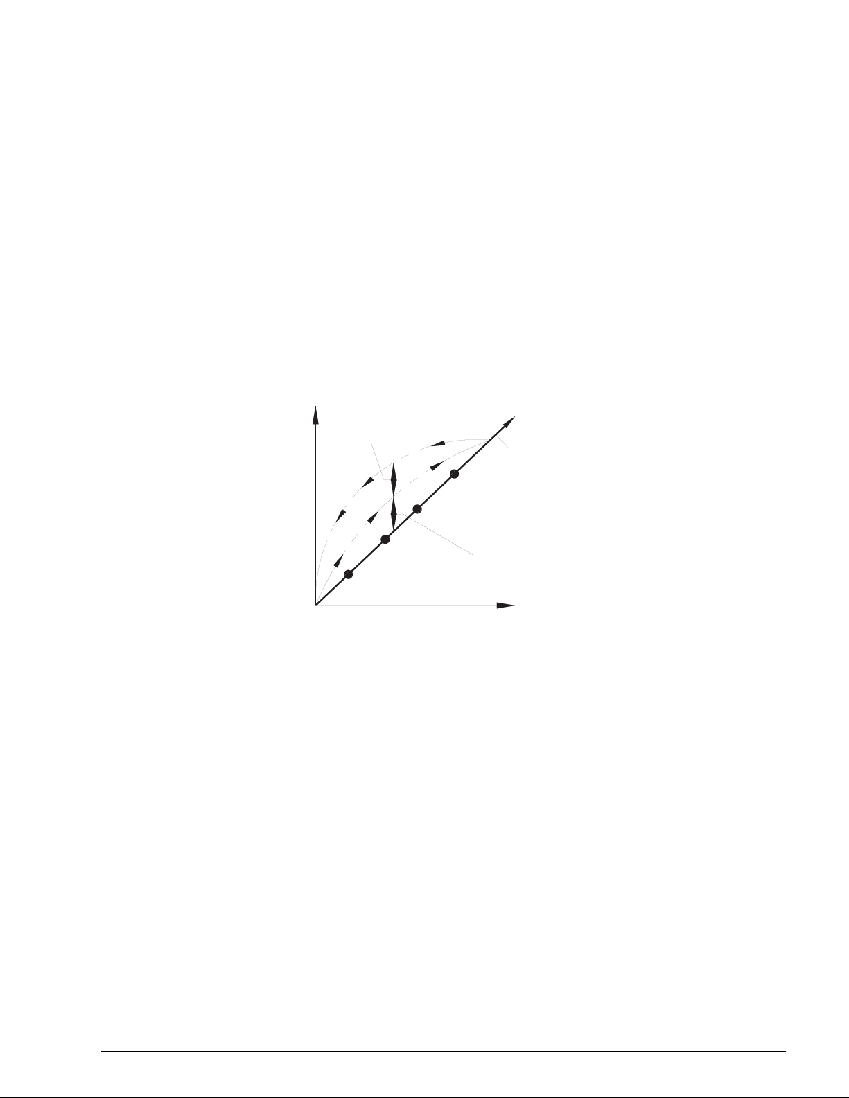
5.8 Span Calibration Points
There are a total of 10 calibration points (SPAN 1 - 10 CAL TARGET) which are sequentially entered. It is not
required that all calibration points be entered. If calibration is performed with less than 10 points, the curve is
extrapolated to full capacity based upon the slope correction between the last two entered SPAN CAL points. In
the example below, if only four span calibration points were entered (SPAN 1 to SPAN 4), the slope correction
from SPAN 4 to full capacity would be defined by the computed slope between SPAN 3 and SPAN 4.
NOTE: If fewer than 10 SPAN CAL points are desired during calibration, simply step past the remaining calibration
points using the DOWN arrow key, until the HYSTERESIS calibration point is reached.
HYSTERESIS\PERROR
DESIRED LINEARITY FROM ZERO TO RATED OUTPUT
SPAN 4
mV/V OUTPUT
SPAN 1
0
LOAD
Figure 5-5. Span Calibration Points
SPAN 3
SPAN 2
NON-LINEARITY\PERROR
5.9 Resetting Span Calibration Points
To reset the span calibration points, use the DOWN arrow key to step to the desired SPAN CAL point and then
press the
CE key. The correction factor of the selected SPAN CAL point and all others beyond will be reset to
unity (see Section 5.6 on page 16).
NOTE: X’s shown on LED display and alpha-numeric display columns represent existing data.
After a reset has been performed, entry of new SPAN CAL points proceeds as described in Section 5.6.1 on
page 17, starting with step 3.
NOTE: If all 10 SPAN CAL points are not used in the calibration, the last span calibration point to appear (SPAN x CAL
TARGET=xx.xx) is not an entered correction point. It only indicates the next span calibration that can be entered.
5.10 Overwriting Span Calibration Points and Hysteresis
Any SPAN CAL point can be overwritten with a new value provided that it remains within the range bounded by
the span calibration points above and below the span point to be overwritten. Figure 5-6 on page 20 shows SPAN
2 CAL point being redefined within the boundaries set by SPAN 1 and SPAN 3. HYSTERESIS can also be
overwritten as long as the new entry is below 80% of the full capacity value. For information on how to reach
SPAN CAL point and HYSTERESIS, see Section 5.6 on page 16.
Configuration and Calibration 19
Page 24
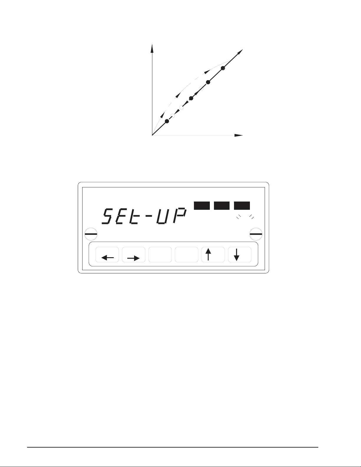
SPAN 4
mV/V OUTPUT
SPAN 2 (ORIGINAL POINT)
SPAN 1
0
LOAD
SPAN 3
Figure 5-6. Overwriting Span Calibration Points
To overwrite a span calibration point or hysteresis, step to the desired point using the DOWN arrow key and then
modify and enter the new value as described in Section 5.6.1 on page 17.
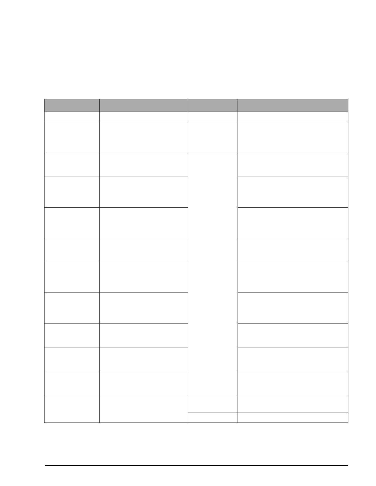
CONFIG ?
ZERO
DISPLAY
TARE PRINT
CE ENTER
YES
NO
Figure 5-7. Configuration Set-Up Mode
20 DLR3110 Rack Mount Digital Pressure Calibrator Manual
Page 25
5.11 Configuration Set-Up Mode Selection
To access Configuration mode, see Section 5.4 on page 13. Press UP and DOWN arrow keys to step through and
select parameters. Press
The Configuration mode may be exited at anytime by pressing the
Exit? YES or NO scrolls continuously until the YES or NO key is pressed. See Figure 5-7 on page 20 for an
example of the DLR3110’s display.
LED Display Alpha-Numeric Display Key Pressed Remarks
SET-UP CONFIG ? YES key Will enter CONFIG menu
LEFT or RIGHT arrow keys to change the current configuration of the selected parameter.
CE key. If the CE key is pressed the prompt
XXX* FILTER 5 UP or DOWN
arrow
AUTO DISP/SEC UP or DOWN
arrow
OFF ZERO % Press LEFT or RIGHT arrow keys to
Full ZERO +/- % Press LEFT or RIGHT arrow keys to
OFF AZM +/- Press LEFT or RIGHT arrow keys to
OFF MOTION Press LEFT or RIGHT arrow keys to
OFF ZERO SET Press LEFT or RIGHT arrow keys to
Press LEFT or RIGHT arrow keys to
change the current configuration of the
selected parameter . 1 to 10 by 1; 10 to 20
by 2; 20 to 50 by 5.
Press LEFT or RIGHT arrow keys to
change the current configuration of the
selected parameter. AUTO, 2, 3 or 5
change the current configuration of the
selected parameter. OFF, 0.5, 1, 2, 5 or
100
change the current configuration of the
selected parameter. Full, 0.05, 0.1, 0.2,
0.5, 1 or 1.5
change the current configuration of the
selected parameter. OFF, 0.5, 1, 3, 5 or 10
change the current configuration of the
selected parameter . OFF, 1, 3, 5, 10, 20 or
50
change the current configuration of the
selected parameter. OFF, Auto.tr or
OFFSET
OFF MIN Press LEFT or RIGHT arrow keys to
change the current configuration of the
selected parameter. OFF or ON
OFF MAX Press LEFT or RIGHT arrow keys to
change the current configuration of the
selected parameter. OFF or ON
OFF FREEZE **Press LEFT or RIGHT arrow keys to
change the current configuration of the
selected parameter. 1 sec to 10 sec by 1
SET-UP EXIT ? YES key Return to MAIN menu SET-UP/CONFIG.
See Section 5.4 on page 13.
NO key Return to XXX/FILTER 5 ?
Table 5-9. Configuration Mode Parameters
* Represent existing data.
** Requires activation by an input. See Section 5.13 on page 23.
Configuration and Calibration 21
Page 26
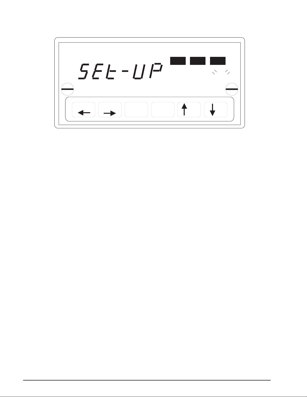
CONV ?
ZERO
DISPLAY
Figure 5-8. Conversion Set-Up Mode
TARE PRINT
CE ENTER
YES
NO
5.12 Conversion Set-Up Mode Selection
To access Conversion mode see Section 5.4 on page 13. Press UP or DOWN arrow keys to step through
conversion selections. Press
The Conversion mode may be e xited at an ytime by pressing the
YES or NO scrolls continuously until the YES or NO key is pressed.
The following is a list of the available conversions as they appear on the alpha-numeric display:
• PSI
•KPa
• mmHG 0
•
C
•BAR
• inHg0
•
C
•mBAR
•cmH
• kg/cm
O
2
2
• inH2O68F
• inH2O4•C
• ftseaH
O
2
•TORR
•metrsH2O
•PASCAL
• mmH
O4•C
2
The following is a list of the inoperative conversions (allocated for future use) as they appear on the
alpha-numeric display:
• CONV.SP1
• CONV.SP2
• CONV.SP1
• CONV.SP2
LEFT or RIGHT arrow keys to change the current state of the selected conversion.
CE key. If the CE key is pressed, the prompt Exit?
22 DLR3110 Rack Mount Digital Pressure Calibrator Manual
Page 27
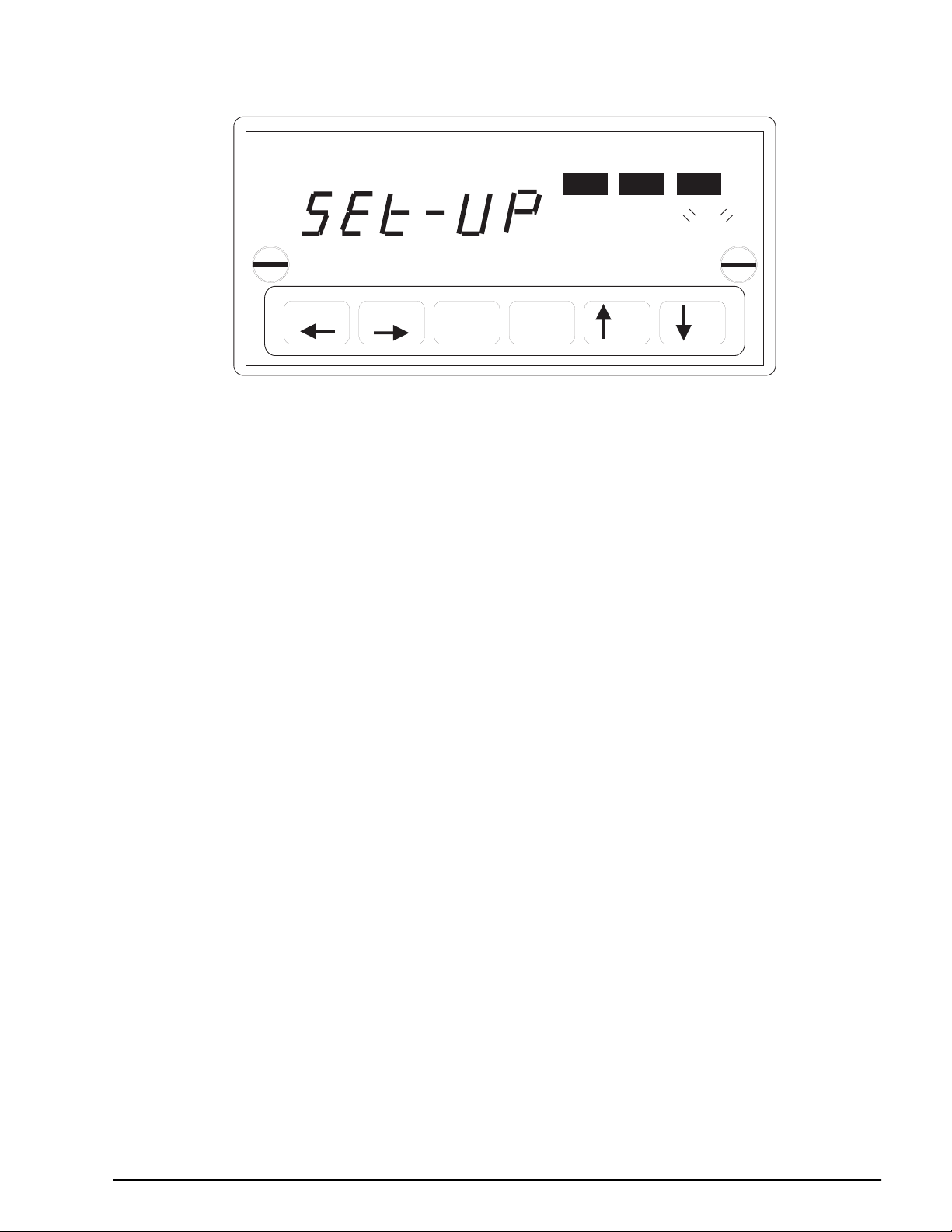
I/O ?
ZERO
DISPLAY
Figure 5-9. Set-Up Mode Selection
TARE PRINT
CE ENTER
YES
NO
5.13 I/O Set-Up Mode Selection
Method 1
I/O (SELECT) - See Section 5.4 on page 13.
Method 2
I/O (DIRECT) - Closing only rocker switch position
mode. See Section 5.3 on page 12.
The I/O SET-UP mode accesses the configuration of available inputs and outputs in the DLR. There are five main
groups of configurable inputs and outputs that are defined as follows:
• Serial I/O - configures ports 1 and 2 for baud rate, parity, continuous or demand, etc.
•Time and date - sets the onboard clock for time and date (allows time and date to be transmitted in the
serial output).
•Parallel output - configures DLR3110 for BCD output. This is an option requiring the installation of the
parallel output option board.
•Analog output - configures DLR3110 for analog output (4-20 mA or 0-10 VDC). This is an option
requiring the installation of the analog output option board.
•Discrete input and outputs - configures two discretes to function as either control output(s) or remote
command input(s).
Press
UP or DOWN arro w k e ys to step through selections. Press LEFT or RIGHT arrow ke ys to change the current
state of the selection. The modes may be exited at any time by pressing the
prompt
Exit? YES or NO scrolls continuously until the YES or NO key is pressed.
3 on switch S1 only places the indicator directly into the I/O
CE key. If the CE key is pressed, the
Configuration and Calibration 23
Page 28
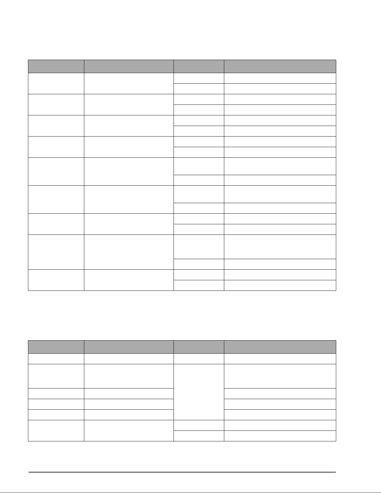
LED Display Alpha-Numeric Display Key Pressed Remarks
SET-UP I/O YES key Enters I/O menu
NO key Continue to PORT 1 ?
SET-UP PORT 1 ? YES key See Section 5.13.1
NO key Continue to PORT 2 ?
SET-UP PORT 2 ? YES key See Section 5.13.6 on page 29
NO key Continue to TIME&D ?
SET-UP TIME&D ? YES key See Table 5-18 on page 29
NO key Continue to PARAL ?
SET-UP PARAL ? YES key Requires the installation of the parallel
output option board
NO key Continue to ANALOG ?
SET-UP ANALOG ? YES key Requires the installation of the analog
output option board
NO key Continue to INPUT ?
SET-UP INPUT ? YES key See Section 5.13.8 on page 30
NO key Continue to TRIP PT ?
SET-UP TRIP PT? YES key Press LEFT or RIGHT arrow keys to
change the current configuration of the
selected parameter. OFF or ON
NO key Continue to EXIT
---- EXIT ? YES key Return to Section 5.4 on page 13
NO key Return to PORT 1 ?
Table 5-10. I/O Set-Up Mode Parameters
5.13.1 Port 1 Set-Up Menu
Table 5-11 outlines the parameters of the Port 1 Set-up menu.
LED Display Alpha-Numeric Display Key Pressed Remarks
SET-UP PORT 1 ? YES key Enters Port 1 Set-up
PORT 1 OFF Press YES key to
to accept, NO
key to exit
PORT 1 PRINTER See Table 5-12 on page 25
PORT 1 DUPLEX See Table 5-14 on page 26
PORT 1 SIMPLEX See Table 5-17 on page 28
---- EXIT ? YES key Return to Table 5-10 on page 24
NO key Return to PORT 1?
Press LEFT or RIGHT arrow keys to
change the current state of the selection.
OFF, PRINTER, DUPLEX, SIMPLEX
Table 5-11. Port 1 Set-Up Menu
24 DLR3110 Rack Mount Digital Pressure Calibrator Manual
Page 29
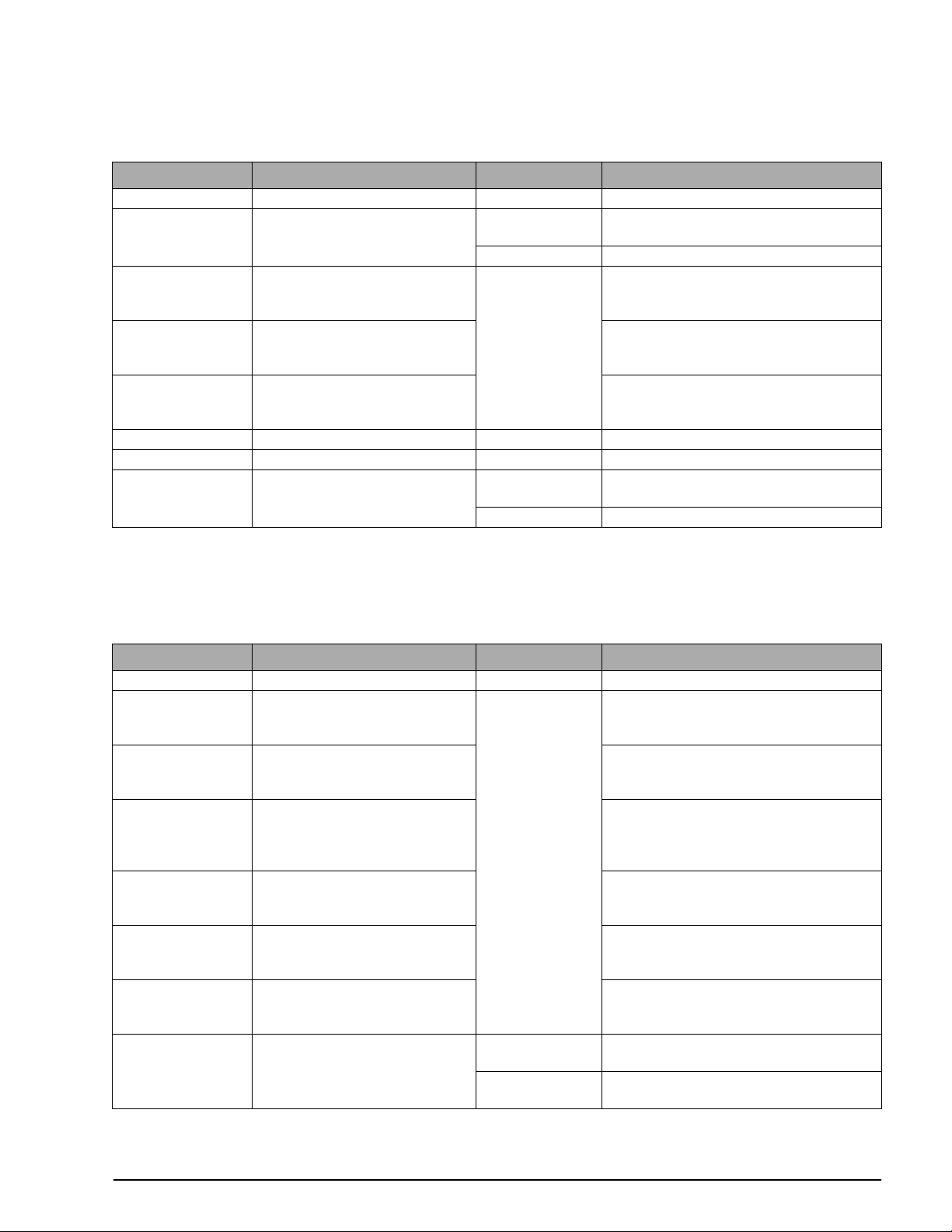
5.13.2 Port 1 Printer Menu
Table 5-12 outlines the parameters of the Port 1 Printer menu.
LED Display Alpha-Numeric Display Key Pressed Remarks
PORT 1 PRINTER DOWN arrow Enters Printer set-up
SET P1 AUTO PR? YES key Enters AUTO PR? menu. Use DOWN arrow
key to scroll PRINT 1 – PRINT 8
NO key Continue to BAUD/9600
BAUD 9600 UP or DOWN
arrow
PARITY EVEN Press LEFT or RIGHT arrow keys to change
PORT 1 ST ANDARD Press LEFT or RIGHT arrow keys to change
PORT 1 MODIFY See Table 5-13 on page 25
PORT 1 CUSTOM Allocated for future use
PORT 1 EXIT ? YES key Return to menu SET-UP/PORT 1 ?. See
NO key Return to PORT 1/PRINTER
Table 5-12. Port 1 Printer Menu
Press LEFT or RIGHT arrow keys to change
the current state of the selection. 1200,
2400, 4800, 9600 or 19200
the current state of the selection. EVEN,
ODD, MARK or NONE
the current state of the selection.
STANDARD, MODIFY or CUSTOM
Table 5-11.
Port 1 Printer Modify Menu
Table 5-13 outlines the parameters of the Port 1 Printer Modify menu.
LED Display Alpha-Numeric Display Key Pressed Remarks
PORT 1 MODIFY DOWN arrow Enters Modify menu
DELAY 1 AUTO UP or DOWN arrow Press LEFT or RIGHT arrow keys to change
the current state of the selection. 1/SEC,
2/SEC, 3/SEC, 4/SEC, 5/SEC or AUTO
T-D1 OFF Press LEFT or RIGHT arrow keys to change
the current state of the selection. ON,
ABOVE, BELOW or OFF
DATA 1 DISPLAY Press LEFT or RIGHT arrow keys to change
the current state of the selection. DISPLAY
or G/T/N (port 1 only). DISPLAY, G/T/N or
COMPRESS (port 2 only).
EOL 1 CR/LF Press LEFT or RIGHT arrow keys to change
the current state of the selection. CR/LF or
CR
SOT 1 STX Press LEFT or RIGHT arrow keys to change
the current state of the selection.
NONE, SOH or STX
EOT 1 NONE Press LEFT or RIGHT arrow keys to change
the current state of the selection.
EOT, ETX, FF, LF or NONE
PORT 1 EXIT ? YES key Return to menu SETUP/PORT 1 ?. See
Table 5-10 on page 24.
NO key Return to menu PORT 1/PRINTER. See
Table 5-12 on page 25.
Table 5-13. Port One Printer Modify Menu
Configuration and Calibration 25
Page 30
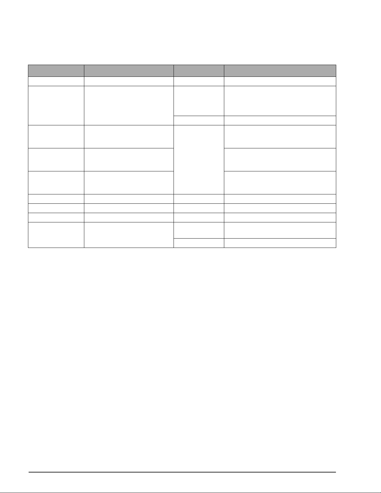
5.13.3 Port 1 Duplex Menu
Table 5-14 outlines the parameters of the Port 1 Duplex menu.
LED Display Alpha-Numeric Display Key Pressed Remarks
PORT 1 DUPLEX DOWN arrow Enters Duplex menu
SET P1 AUTO DU? YES key Enters AUTO DU? menu. Press LEFT or
RIGHT arrow keys to change the current
state of the selection. DUPLEX 1?, DUPLEX
2?, DUPLEX 3? or DUPLEX 4?
NO key Continue to BAUD/9600
BAUD 9600 UP or DOWN
arrow
PARITY EVEN Press LEFT or RIGHT arrow keys to change
PORT 1 ST ANDARD Press LEFT or RIGHT arrow keys to change
PORT 1 MODIFY See Table 5-15 on page 27
PORT 1 RS-485 See Table 5-16 on page 28
PORT 1 CUSTOM Allocated for future use
PORT 1 EXIT ? YES key Return to menu SET-UP/PORT 1 ?. See
NO key Return to PORT 1/DUPLEX
Press LEFT or RIGHT arrow keys to change
the current state of the selection.
1200, 2400, 4800, 9600 or 19200
the current state of the selection.
EVEN, ODD or MARK
the current state of the selection.
STANDARD, MODIFY, RS-485 or CUSTOM
Table 5-11 on page 24.
Table 5-14. Port 1 Duplex Menu
26 DLR3110 Rack Mount Digital Pressure Calibrator Manual
Page 31
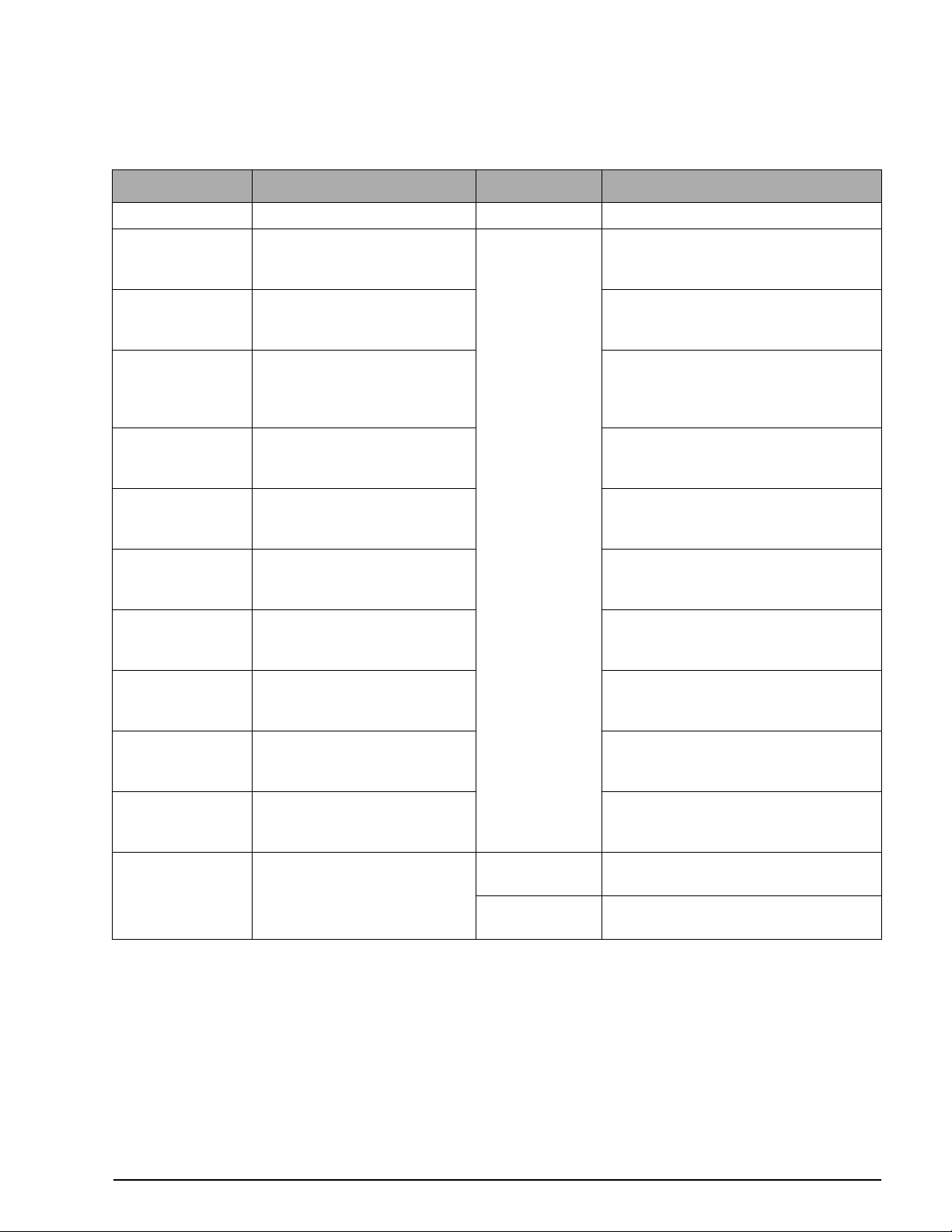
Port 1 Duplex Modify Menu
Table 5-15 outlines the parameters of the Port 1 Duplex Modify menu.
LED Display Alpha-Numeric Display Key Pressed Remarks
PORT 1 MODIFY DOWN arrow Enters Modify menu
PORT 1 PTR OFF UP or DOWN
arrow
PORT 1 CONT OFF Press LEFT or RIGHT arrow keys to
DELAY 1 AUTO
(if either PTR or CONT is ON)
T-D1 OFF
(if either PTR or CONT is ON)
DATA 1 DISPLAY
(if either PTR or CONT is ON)
EOL 1 CR/LF
(if either PTR or CONT is ON)
SOT 1 STX
(if either PTR or CONT is ON)
EOT 1 NONE
(if either PTR or CONT is ON)
Press LEFT or RIGHT arrow keys to
change the current state of the selection.
PTR OFF or PTR ON
change the current state of the selection.
CONT OFF or CONT ON
Press LEFT or RIGHT arrow keys to
change the current state of the selection.
1/SEC, 2/SEC, 3/SEC, 4/SEC, 5/SEC or
AUTO
Press LEFT or RIGHT arrow keys to
change the current state of the selection.
ON LINE, ABOVE, BELOW or OFF
Press LEFT or RIGHT arrow keys to
change the current state of the selection.
DISPLAY or G/T/N
Press LEFT or RIGHT arrow keys to
change the current state of the selection.
CR/LF or CR
Press LEFT or RIGHT arrow keys to
change the current state of the selection.
NONE, SOH or STX
Press LEFT or RIGHT arrow keys to
change the current state of the selection.
EOT, ETX, FF, LF or NONE
CHECK NONE Press LEFT or RIGHT arrow keys to
change the current state of the selection.
NONE, XOR or CHECKSUM
RESP ACK/NAK Press LEFT or RIGHT arrow keys to
change the current state of the selection.
ECHO, ACK/NAK or NONE
PORT 1 EXIT ? YES key Return to menu SET-UP/PORT 1 ?. See
Table 5-10 on page 24.
NO key Return to menu PORT 1/DUPLEX. See
Table 5-14 on page 26.
Table 5-15. Port 1 Duplex Modify Parameters
Configuration and Calibration 27
Page 32
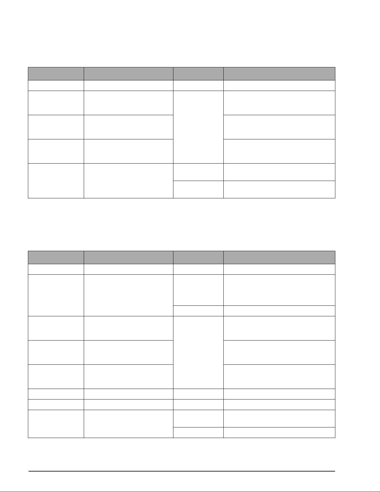
5.13.4 Port 1 RS485 Menu
Table 5-16 outlines the parameters of the Port 1 RS485 menu.
LED Display Alpha-Numeric Display Key Pressed Remarks
PORT 1 RS485 DOWN arrow Enters RS485 menu
ADDR 1 UP or DOWN
arrow
CHECK NONE Press LEFT or RIGHT arrow keys to
RESP ACK/NAK Press LEFT or RIGHT arrow keys to
PORT 1 EXIT ? YES key Return to menu SET-UP/PORT 1 ?. See
NO key Return to menu PORT 1/DUPLEX. See
Press LEFT or RIGHT arrow keys to
change the current state of the selection.
See Section 5.7 on page 19
change the current state of the selection.
NONE, XOR or CHECKSUM
change the current state of the selection.
ECHO, ACK/NAK or NONE
Table 5-10 on page 24.
Table 5-14 on page 26.
Table 5-16. Port 1 RS485 Menu
5.13.5 Port 1 Simplex Menu
Table 5-17 outlines the parameters of the Port 1 Simplex menu.
LED Display Alpha-Numeric Display Key Pressed Remarks
PORT 1 SIMPLEX DOWN arrow Enters Simplex menu
SET P1 AUTO SI? YES key Press LEFT or RIGHT arrow keys to
change the current state of the selection.
SIMPLX 1?, SMPLX 2?, SMPLX 3? or
SMPLX 4?
NO key Continue to BAUD/9600
BAUD 9600 UP or DOWN
arrow
PARITY EVEN Press LEFT or RIGHT arrow keys to
PORT 1 STANDARD Press LEFT or RIGHT arrow keys to
PORT 1 MODIFY See Table 5-16 on page 28
PORT 1 CUSTOM Allocated for future use
PORT 1 EXIT ? YES key Return to menu SET-UP/PORT 1 ?. See
NO key Return to PORT 1/SIMPLEX
Press LEFT or RIGHT arrow keys to
change the current state of the selection.
1200, 2400, 4800, 9600 or 19200
change the current state of the selection.
EVEN, ODD, MARK or NONE
change the current state of the selection.
STANDARD, MODIFY or CUSTOM
Table 5-10 on page 24.
Table 5-17. Port 1 Simplex Parameters
28 DLR3110 Rack Mount Digital Pressure Calibrator Manual
Page 33
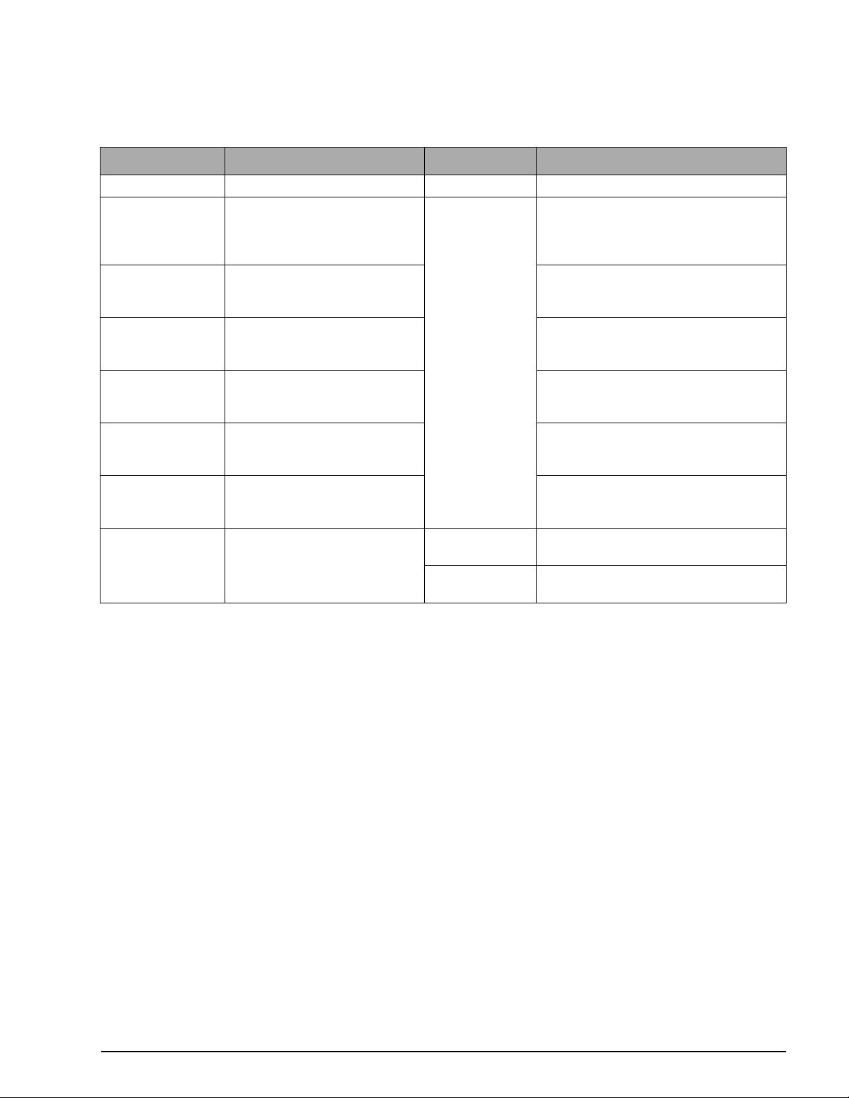
Port One Simplex Modify Menu
Table 5-18 outlines the parameters of the Port 1 Simplex Modify menu.
LED Display Alpha-Numeric Display Key Pressed Remarks
PORT 1 MODIFY DOWN arrow Enters Modify menu
DELAY 1 AUTO UP or DOWN
arrow
T-D1 OFF Press LEFT or RIGHT arrow keys to
DATA 1 DISPLAY Press LEFT or RIGHT arrow keys to
EOL 1 CR/LF Press LEFT or RIGHT arrow keys to
SOT 1 STX Press LEFT or RIGHT arrow keys to
EOT 1 NONE Press LEFT or RIGHT arrow keys to
PORT 1 EXIT ? YES key Return to menu SET-UP/PORT 1 ?. See
NO key Return to menu PORT 1/SIMPLEX. See
Press LEFT or RIGHT arrow keys to
change the current state of the selection.
1/SEC, 2/SEC, 3/SEC, 4/SEC, 5/SEC or
AUTO
change the current state of the selection.
ON ONE, ABOVE, BELOW or OFF
change the current state of the selection.
DISPLAY, G/T/N or COMPRESS
change the current state of the selection.
CR/LF or CR
change the current state of the selection.
NONE, SOH, or STX
change the current state of the selection.
EOT, ETX, FF, LF, or NONE
Table 5-10 on page 24.
Table 5-17 on page 28.
Table 5-18. Port 1 Simplex Modify Parameters
5.13.6 Port 2 Set-Up
Port 2 has the same set-up as Port 1 for the PRINTER or SIMPLEX modes. Port 2 does not have a DUPLEX
mode. All references to Port 1 are replaced with Port 2 for its PRINTER or SIMPLEX modes.
Configuration and Calibration 29
Page 34
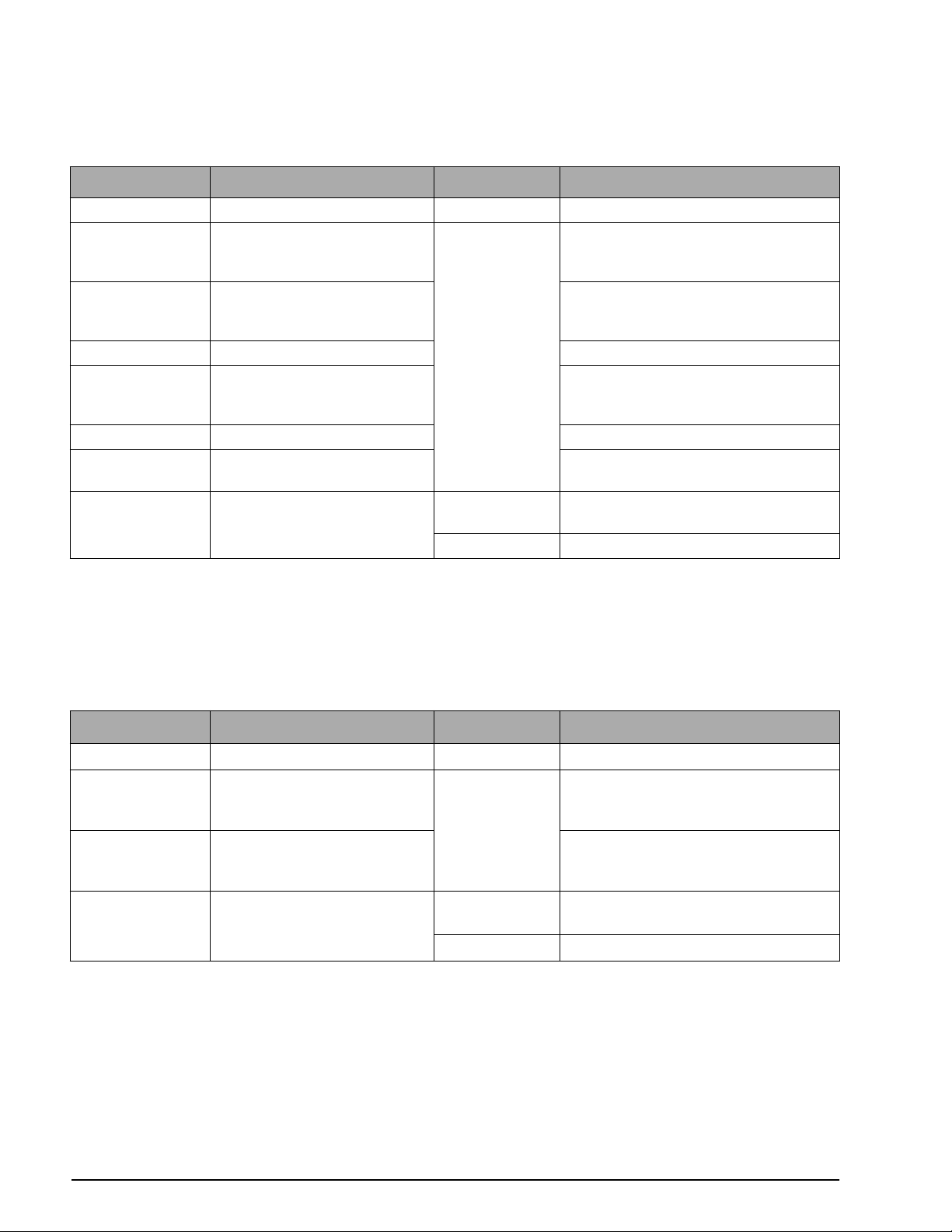
5.13.7 Time and Date Set-Up Menu
Table 5-19 outlines the Time and Date Set-Up menu parameters of the DLR3110.
LED Display Alpha-Numeric Display Key Pressed Remarks
SET-UP TIME&D ? YES key Enters Time and Date menu
TSTANDARD UP or DOWN
arrow
T 12 HOUR Press LEFT or RIGHT arrow keys to
T 6:29 PM See Section 5.7 on page 19.
DATE MM/DD/YY Press LEFT or RIGHT arrow keys to
DATE 10/04/00 See Section 5.7 on page 19.
DATE NUMBER NUMBER or LETTER (print-out format of
PORT 1 EXIT ? YES key Return to menu SET-UP/TIME&D ? See
NO key Return to T/STANDARD.
Press LEFT or RIGHT arrow keys to
change the current state of the selection.
STANDARD or DLS (Day Light Savings)
change the current state of the selection.
12 HOUR or 24 HOUR
change the current state of the selection.
MM/DD/YY or DD/MM/YY
date)
Table 5-10 on page 24.
Table 5-19. Time and Date Set-Up Menu
NOTE: Setting the time is performed in the 24 hour clock mode for both 12 and 24 HOUR selections.
5.13.8 Input Set-Up
Table 5-20 outlines the parameters of the Input Set-up menu.
LED Display Alpha-Numeric Display Key Pressed Remarks
SET-UP INPUT YES key —
INPUT.1 OFF UP or DOWN
arrow
INPUT.2 OFF Press LEFT or RIGHT arrow keys to
---- EXIT ? YES key Return to menu SET-UP/INPUT ?. See
NO key Return to SET-UP/INPUT.1
Table 5-20. Input Set-Up Parameters
Press LEFT or RIGHT arrow keys to
change the current state of the selection.
FREEZE, ZERO, TARE, PRINT or OFF
change the current state of the selection.
FREEZE, ZERO, TARE, PRINT or OFF
Table 5-10 on page 24.
30 DLR3110 Rack Mount Digital Pressure Calibrator Manual
Page 35
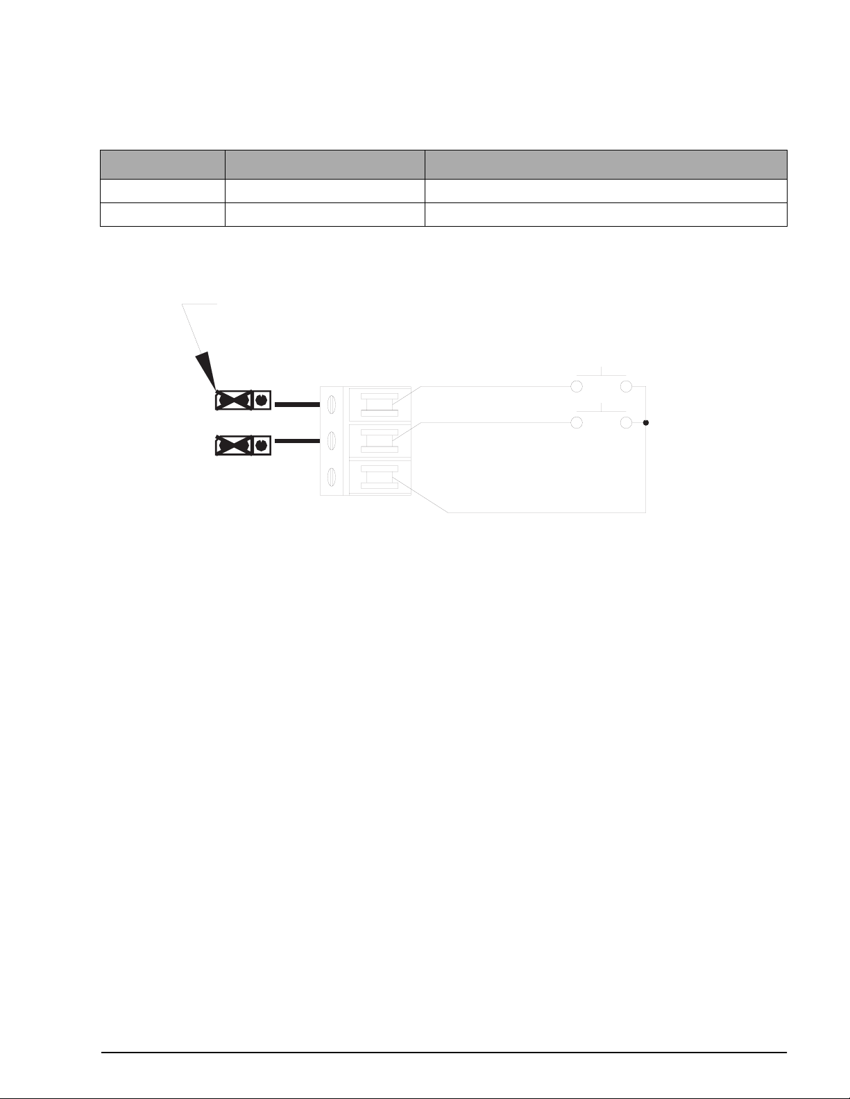
5.13.9 Print and Zero Wiring Configration Example
Table 5-21 illustrates a typical wiring configuration to operate the PRINT and ZERO commands remotely.
LED Display Alpha-Numeric Display Remarks
INPUT.1 ZERO INPUT 1 assigned as a ZERO input
INPUT.2 PRINT INPUT 2 assigned as a PRINT input
Table 5-21. Wiring Configuration Example
JUMPER PLUGS SHOWN ON S4 & S5 CONFIGURED AS AN INPUT
PRINT
S5
I/O 2
IN
S4
OUT
TB2
I/O 1
RETURN
ZERO
(DIGITAL COMMON)
Figure 5-10. Remote Print and Zero Wiring Example
Configuration and Calibration 31
Page 36
6.0 Serial Input/Output
The DLR3110 offers easy access and configuration of two serial communication ports. Both communication
ports are ASCII-compatible and thus the serial data output formats are compatible with most printers,
scoreboards, or other remote serial devices. Port One may be configured for bi-directional full duplex or half
duplex (duplex = two way communication) mode of operation while Port Two is restricted to a simplex output
mode only (simplex = one way communication). The two communication ports support both RS232 and 20 mA
current loop (passive or active). In addition, Port One also supports RS485, or RS422 communication.
The transmission of serial output data strings can be initiated in one of three ways: on demand output, continuous
output, or by serially soliciting the indicator in a duplex (bi-directional) mode of communication.
Section 5.13 on page 23 for configuring.
Port 1 (set up selections)
• OFF - Turns Port One off
•
PRINTER - On demand printout of the data when the PRINT key is pressed or the remote print input is
issued. The printer mode is a simplex output mode.
•
DUPLEX - Bi-directional communication in which serial data can be both received and transmitted
between the indicator and a remote device such as a computer.
•
SIMPLEX - Continuous serial transmission
Port 2 (set up selections) - No DUPLEX communication
• OFF - Turns Port Two of f
•
PRINTER - On demand printout of the data when the PRINT key is pressed or the remote print input is
issued. The printer mode is a simplex output mode.
•
SIMPLEX - Continuous serial transmission
See
6.1 ASCII - Data Formats
Each serial character sent out in the serial data string is in ASCII - compatible format. The data format selection
is based on parity selection in the I/O set-up mode (Refer to Section 5.13 on page 23 for configuration of Serial
Ports). The data format for each ASCII character is of the general form
One ASCII character consists of:
(1) Start Bit,
(7) or (8) Data Bits (data bits are the bits that actually encode for the ASCII character)
(1) or No Parity Bit
(1) Stop Bit
Bit Parity Selection Odd Even Mark None
Start Bit ASCII Data Formats 1111
Data Bit 7778
Parity Bit
Stop Bit 1121
Table 6-1. Various Data Formats Available Through Parity Selection
11(No Parity) (No Parity)
described below.
32 DLR3110 Rack Mount Digital Pressure Calibrator Manual
Page 37
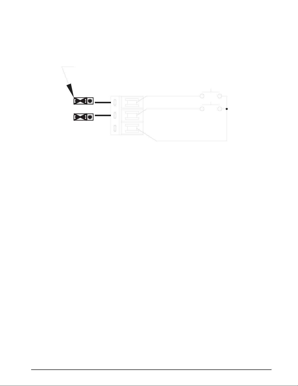
6.2 Printer (Port One or Port Two)
The selection of the PRINTER format is an on-demand serial data transmission that is initiated each time the
front panel
when interfacing to printers.
The data output format of the serial transmission is of the general form shown below:
Where:
PRINT key is pressed or when a remote print input is issued. This mode of serial data output is used
JUMPER PLUGS SHOWN ON S4 & S5 CONFIGURED AS AN INPUT
PRINT
S5
I/O 2
IN
S4
OUT
I/O 1
TB2
(DIGITAL COMMON)
Figure 6-1. Printer Port One and/or Port Two Wiring
RETURN
PRINT
<Pol><Data><space><Units><space><Mode><space><space><CR><LF>
<,> = Brackets are not sent in the transmission of the output data string.
Pol = Single character field that defines polarity of data. Positive data would be space character
(20H) and negative data will have a “-” character (2DH).
Data = Seven (7) digit numeric data field that includes decimal point and/or fixed dummy zero when
applicable. Leading zeroes are suppressed and an ASCII space character (20H) is
transmitted to hold the position of each leading zero.
space = Space character (20H)
Units = A character field that defines the current units of the display data (examples: PSI, cmH2O,
Kpa, mBAR, BAR, PASCAL).
Mode = An alpha character field that describes the current mode the indicator is in. GAGE/
ABSOLUTE/Delta P
CR = Carriage return
LF = Line feed
6.3 Duplex (Port One Only)
The selection of the DUPLEX format is only available on Port One. This selection sets up port 1 for bidirectional
communication in RS485, RS232, or 20mA. Because of the extensive list of command instructions that can be
issued to the indicator from a host computer, the scope of this section is limited to defining those commands that
are most often utilized. A more extensive document detailing the full operational parameters for serial duplex
protocol is available upon request from CONDEC. Ask for Duplex Serial Protocol Manual, PN 74845.
• The duplex protocol includes the following basic functions:
d) Setup entry and recall
e) Current weight/pressure data recall
f) Calibration and correction recall and entry
g) All front panel key functions
h) Temperature calibration and correction recall and entry
Serial Input/Output 33
Page 38

• The protocol between the “standard” full duplex and the RS485 only differ by the addition of the origin
and destination address characters.
•All functions performed via the front panel keys can also be performed via the serial full duplex
communications.
6.3.1 Full Duplex Protocol
Communications from the host computer to the DLR:
<*><DD><OO><cmd><{><data entry><}><CHECK><CR>
NOTE: Destination and origin characters (<DD> and <OO>) are only sent in RS485 format
Response from the DLR:
<:><OO><DD><cmd r><{><data resp><}><CHECK><CR>
Where:
"<",">" = Brackets are not sent
* = Message from master (host computer [2AH])
: = Response from DLR3110 (3AH)
DD = DLR unit address (two digit) if in RS485
OO = Master address (fixed at 00) if in RS485
If RS485 mode is not selected the "DD" and "OO" are not transmitted.
cmd = Three character command to DLR3110
cmd r = Three character command echoed from DLR3110
{ = Start of data character (7BH)
} = End of data character (7DH)
'{' and '}' only sent if data entry or recall.
data entry = Data entered into DLR if entry command
data resp = Data response from DLR if in response
CHECK = Optional two character check if selected
CR = Message terminator (0DH)
A "LF" character following the "CR" is ignored. All characters following the "CR"
and preceding the "*" is ignored.
6.3.2 Command Code <cmd> Description
The <cmd> consists of three (3) characters “ppt” where:
pp = the command parameter (see chart I)
t = the command type
The three (3) command types (t) are as follows:
Direct cmd code = < D > character (44H). “D” commands have no data associated with them
Examples:
•General commands (Zero, Tare, etc.)
•Display Mode commands (Gross, Peak, etc.)
•Weight calibration (Zero Cal, etc.)
Data request code = < R > character (3FH). “R” commands are requests for data from the host to the
DLR
Examples:
•Weight/pressure data
• Status
• Setup data
•Calibration data
34 DLR3110 Rack Mount Digital Pressure Calibrator Manual
Page 39
Data entry code = < E > character (45H). Commands with data sent from the host to be entered into
the DLR.
Examples:
• Setup data
•Calibration data
6.3.3 Basic RS485 Commands
Unit address 01 is used in Table 6-2 for illustration.
NOTE: A more extensive document detailing the full RS485 command codes is available upon request from CONDEC.
Ask for Duplex Serial Protocol Manual, PN 74845.
Polling Command Function
<*><01><00><PDR><cr> Request for the display data
<*><01><00><PGR><cr> Request for the pressure data (irregardless of the current
display data
<*><01><00><PPR><cr> Request for the max data
<*><01><00><PMR><cr> Request for the min data
<*><01><00><ZED><cr> Issues a ZERO command to the pressure indicator
Table 6-2. Basic RS485 Commands
6.4 Continuous Simplex Output (Compressed Format)
The pressure value that is compressed consists of the polarity and pressure value including the <dp>. The data in
the compress mode is based on the six-digit display plus a <dp> when required. To enable see Section 5.13.1 on
page 24.
The data output format of the serial transmission is of the general form shown below:
<-/D06><D05><D04><D03><D02><D01><lb1><lb2><lb3><lb4>
Where:
<-/D06> = The minus character if present and the most significant digit if positive.
<D05>--<D01> = The pressure digits.
<lb1>--<lb4> = Rest of data not effected (for example: units, mode).
The floating <dp> is added to the string when required. Therefore, the string is one character longer
when a <dp> is added.
Examples:
100.0--<sp> <sp> <1> <0> <0> <dp> <0> --123456-- <1> <2> <3> <4> <5> <6> ---
- 345.6 -- <-> <sp> <3> <4> <5> <dp> <6> ---
6.5 Serial Output Wiring and Hardware Configuration
This section details the wiring configuration for serial transmission to a remote device such as a printer. All direct
wiring on terminal block (TB3) and hardware settings are well marked and can be located at the rear portion of
the CPU board assembly.
Serial Input/Output 35
Page 40
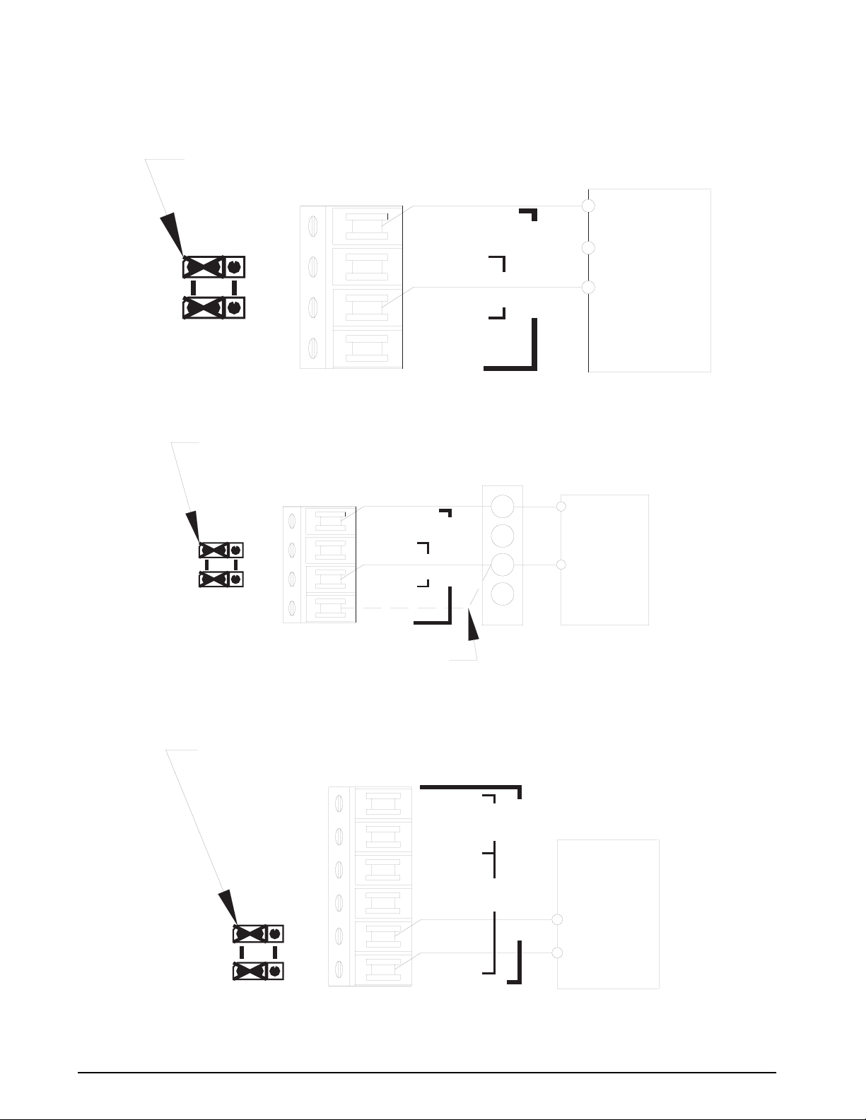
The DLR3110 comes equipped with a 25 pin “D” female serial I/O connector (J6) mounted at the rear of the
enclosure which provides access to Port One - RS232 or
RS485 hook up.
JUMPER PLUGS SHOWN ON S6 & S7 CONFIGURED AS RS232
P1
RS232
P1
RS232
S7
SIG COM
RS422
IN
BA
OUT
S6
TB3
OUT
1
P2
Figure 6-2. Port One RS232 (Simplex) - Direct CPU Terminal Block (TB3) Wiring
JUMPER PLUGS SHOWN ON S6 & S7 CONFIGURED AS RS232
J6
P1
RS232
S7
S6
TB3
RS422
BA
BLACK WIRE
SIG COM
IN
OUT
OUT
1
RS232
P1
P2
7
2
SIG COM
RXD (IN)
REMOTE DEVICE
SIG COM
TXD (OUT)
RXD (IN)
REMOTE DEVICE
MOVE RED WIRE TO THE PORT 2 OUT POSITION FOR PORT 2 WIRING HOOK-UP
Figure 6-3. Port One RS232 (Simplex) - J6 (25 Pin “D”) Wiring
JUMPER PLUGS SHOWN ON S8 & S9 CONFIGURED AS PORT 1 20mA LOOP
10
20mA LOOP
P2
REMOTE DEVICE
P1
-RX (IN)
+RX (+IN)
20mA
S9
S8
RS485
AB
-OUT
+OUT
-IN
+IN
-OUT
+OUT
Figure 6-4. Port One RS232 Active 20mA Loop (Simplex) - Direct CPU Terminal Block (TB3) Wiring
36 DLR3110 Rack Mount Digital Pressure Calibrator Manual
Page 41
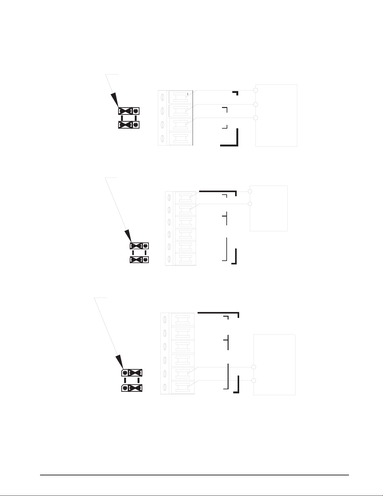
JUMPER PLUGS SHOWN ON S6 & S7 CONFIGURED AS RS232
P1
RS232
S7
S6
TB3
RS422
BA
SIG COM
IN
OUT
1
OUT
RS232
P1
P2
SIG COM
TXD (OUT)
RXD (IN)
REMOTE DEVICE
Figure 6-5. Port One RS232 (Full Duplex) - Direct CPU Terminal Block (TB3) Wiring
JUMPER PLUGS SHOWN ON S8 & S9 CONFIGURED AS PORT 1 RS485
10
-RX (-IN)
+RX (+IN)
REMOTE DEVICE
20mA
S9
S8
RS485
AB
-OUT
+OUT
-IN
+IN
-OUT
+OUT
P2
P1
20mA LOOP
Figure 6-6. Port One RS232 (Full Duplex) - J6 (25 Pin “D”) Wiring
JUMPER PLUGS SHOWN ON S8 & S9 CONFIGURED AS PORT 1 RS485
10
20mA LOOP
P2
P1
REMOTE DEVICE
A
B
20mA
S9
S8
RS485
AB
-OUT
+OUT
-IN
+IN
-OUT
+OUT
Figure 6-7. Port One RS485 Two Wire (Half Duplex) - Direct CPU Terminal Block (TB3) Wiring
Serial Input/Output 37
Page 42
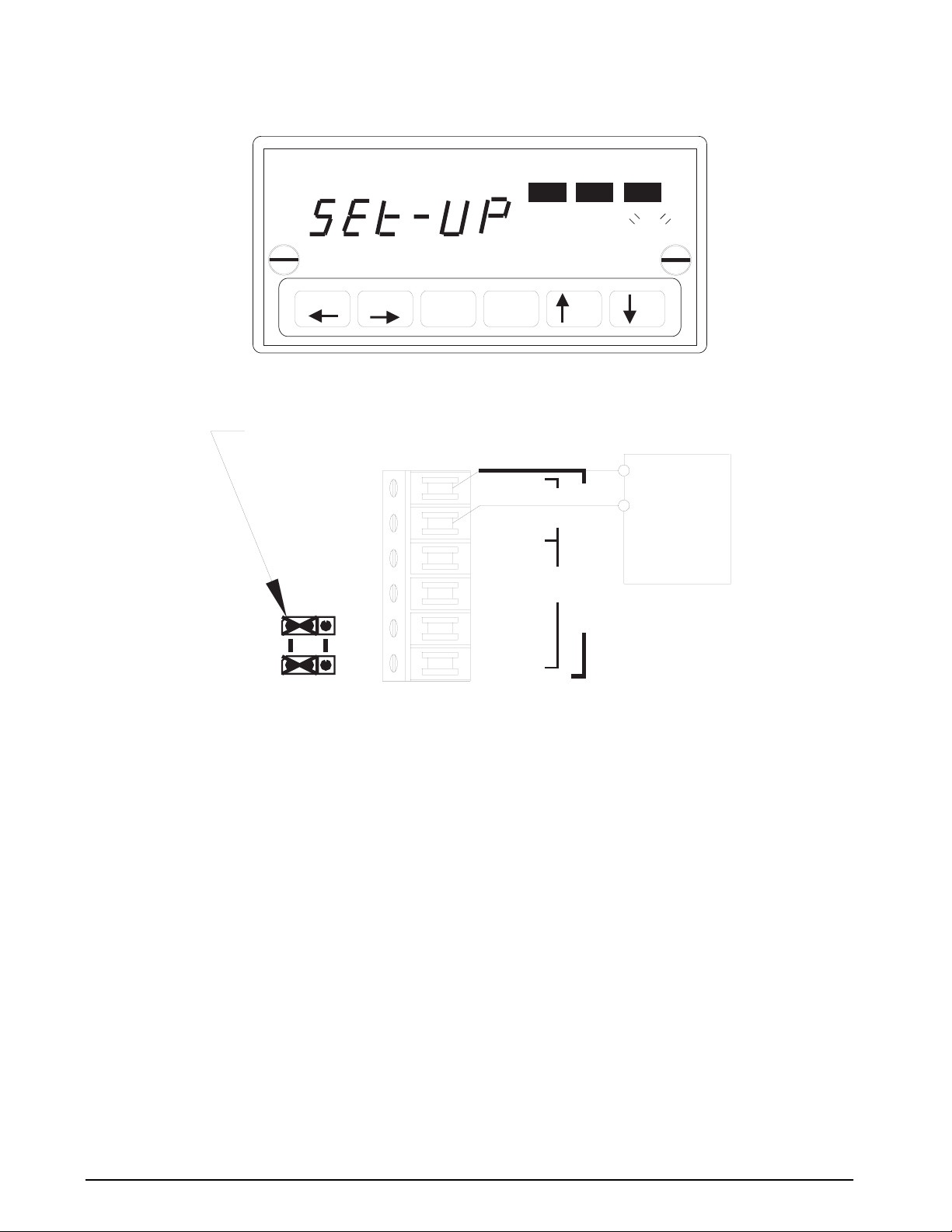
CONV ?
ZERO
DISPLAY
TARE PRINT
CE ENTER
YES
NO
Figure 6-8. Port Two RS232 (Simplex) - Direct CPU Terminal Block (TB3) Wiring
JUMPER PLUGS SHOWN ON S8 & S9 CONFIGURED AS PORT 1 RS485
10
-RX (-IN)
20mA LOOP
-OUT
P2
+RX (+IN)
+OUT
-IN
P1
REMOTE DEVICE
+IN
20mA
AB
RS485
S9
-OUT
+OUT
S8
Figure 6-9. Port Two RS232 Active 20mA Current Loop (Simplex) - Direct CPU Terminal Block (TB3) Wiring
38 DLR3110 Rack Mount Digital Pressure Calibrator Manual
Page 43
7.0 Maintenance and Service
The following sections cover troubleshooting, maintenance and service procedures for the DLR3110.
7.1 Troubleshooting
Symptom Problem Remedy
No lit display Unit does not energize Check fuse, check power source, check
power switch
Display slowly decreases over time Leak in system Check all compression and pipe fittings
with SNOOP
detector (PN 64781)
Display does not respond when Vernier
knob is turned
Display increases or decreases when
INPUT (Pressure) or VENT valves are
closed
Unit will not stay in CAL, display shows
"-0L- -OVER-", or display reads a high
value @ zero PSIG
Display does not zero Display does not zero Perform a ZERO/SPAN calibration
Display shifts, is not steady Transducer drifts or possible over
No Vernier control Readjust isolation valves on Orion;
replace O-ring on Vernier piston
No Pressure or Vent control Replace valve seats or o-rings in valves;
check valve needles
Transducer over-pressurized Replace transducer
Replace transducer
pressure
*
®
, bottle of liquid leak gas
Table 7-1. DLR3110 Troubleshooting
*SNOOP
®
is a registered trademark of Swagelok.
7.2 Maintenance and Service Procedures
This section outlines the mechanical and basic electrical repair procedures for the rack-mount pneumatic
pressure calibrator, model DLR3110. The repair procedures co v er the major components and sub-assemblies that
are critical to the proper functioning of the calibrators and that need periodic maintenance over the life of the
unit. Only those persons who are formally trained as skilled technicians should attempt to repair these units. All
relevant safety precautions should be observed due to the presence of electrical components and high-pressure
components.
NOTE: Based on model, the following may give information on components that are not part of your DLR3110.
7.2.1 Panel/Chassis Removal and Installation
Removal
Tools required: Phillips screwdriver
1. Vent system and remove input pressure source. Disconnect power cord, hoses, connectors, etc. from rear
of DLR3110. Remove from rack, if applicable, by grasping the handles located on the front of the unit
and gently set the rack-mount assembly on a bench top. It can be rested on the panel bottom and chassis
edge.
2. Loosen and remove the three screws (PN 14839) from rear and sides that secure the co ver to the chassis.
Installation
Tools required: Phillips screwdriver
1. Align mounting holes of cover with chassis and install three screws (PN 14839) from rear and sides that
secure the cover to the chassis.
2. Lift the panel and chassis by grasping the handles located on the front of the unit and re-install in rack, if
applicable. Connect input pressure source, power cord, hoses, connectors, to rear of DLR3110.
Maintenance and Service 39
Page 44

7.2.2 ORION-2C (PN 55283) or ORION-3A (PN 55287) Manifold Removal
Tools required: Phillips screwdriver
11/32" wrench or nutdriver
.061" hex wrench
adjusting screwdriver (small flat blade)
11/32" open end wrench (thin)
7/16" open end wrench
1. Vent any remaining gas from the system to atmosphere.
2. Remove cover from chassis as described in Section 7.2.1 on page 39.
3. Remove the test port to Orion tubing section using a 7/16" wrench.
4. If the transducer is wired via a connector, remove the connector by turning counter-clockwise. If the
transducer is hard-wired, loosen and remove the four transducer wires (red, white, green, black) from the
terminal block, TB1, on the CPU board, using the small flat-blade screwdriver.
5. Break the wire ties, if applicable, that hold the transducer wires so that the wires are free.
6. Using the 11/32" thin wrench, loosen and carefully remove the transducer from the Orion-2C manifold.
7. Remove the tubing sections from the vent and pressure inlet fittings on the Orion-2C, using a 7/16"
wrench.
8. Remove the panel knobs from the Coarse (pressure), Vernier and Vent valves using the .061" hex wrench.
9. Loosen and remove the two panel scre ws (PN 60837) from the panel front that secure the manifold to the
panel.
10. Remove the manifold from the front panel.
7.2.3 ORION Manifold - Valve Seat Removal
ORION- 2C: Refer to Section 7.3 on page 53 and Figure 7-1 on page 55.
ORION- 3A: Refer to Section 7.4 on page 57 and Figure 7-2 on page 59.
Tools required: A/R solvent (denatured alcohol)
socket wrench
3/4" socket
female socket (65581)
needle housing socket (65580)
isolation valve needle housing socket (PN 59793)
hex wrench (.050")
hex wrench (.061")
torque wrench
needle-nose pliers
tube fluorinated Krytox grease (PN 55593)
electric hand drill
No. 43 drill bit
No. 4-40 tap
tap handle
small hammer
1. Secure the manifold by its center portion, in a bench vise, with the valve knobs pointing upward.
2. Using the .061" hex wrench, loosen and remove the knob inserts (4) from the pressure and vent valve
stems.
3. Using the .050" hex wrench, loosen and remove the set screw (34) and lock nut (2).
4. Loosen the 3/4" locknuts (1) on the pressure and vent valve threaded needle housings (10).
5. Using the needle housing socket (65580) and torque wrench, loosen and remove the needle/housing
assembly (10, 1).
6. To disassemble the isolation valve, first remove the valve needle (18) by turning the gear clockwise.
7. Loosen and remove the valve housings (19) using the isolation valve housing removal socket (59793)
female socket (65581) and torque wrench.
8. Remove the valve stem seats (8) and valve needle seats (9) using the needle-nose pliers.
9. Remove the inner and outer O-rings (28, 27) and back-up rings (31, 30) from the valve stem seats and
wash all parts in solvent (denatured alcohol).
40 DLR3110 Rack Mount Digital Pressure Calibrator Manual
Page 45

10. To remove valve seats (7) from either the coarse (pressure), vent or isolation valves, try blowing
compressed air through the inlet and outlet fittings. Otherwise, the center holes have to be drilled and a
tap used to extract the seat (Steps 11-14).
11. Using the electric hand drill with the No. 43 bit, carefully drill out the seat hole, ensuring that the drill
does not touch the hole in the manifold housing directly beneath the seat.
12. Blow out any chips from the seat area using compressed air.
13. While holding the 4-40 tap steady and perpendicular to the seat, slowly turn until the tap starts to engage
the seat.
14. When the tap has engaged into the seat, use a small hammer and gently knock upward against the tap
handle to extract the seat.
15. After the seat has been removed, blow any remaining chips from the seat area.
7.2.4 ORION Manifold - Vernier Control Disassembly
ORION- 2C: Refer to Section 7.3 on page 53 and Figure 7-1 on page 55.
ORION- 3A: Refer to Section 7.4 on page 57 and Figure 7-2 on page 59.
Tools required: A/R solvent (denatured alcohol)
1-1/4" open end wrench
screwdriver (flat-blade)
socket wrench
isolation valve needle housing socket (PN 68508)
isolation valve needle housing socket (PN 68509)
1. With the manifold housing mounted in a vise, turn the vernier shaft (14) clockwise until the piston is
bottomed.
2. Loosen and remove the end cap (13) using a 1-1/4" wrench. At certain points during removal the end cap
will appear to lock up. If this occurs, rotate the shaft clockwise until the end cap is free to turn.
3. Remove the O-ring (29) from the end cap.
ORION-3A: Also remove the backup washer (38) from the end cap.
4. Remove the self-sealing screw (36) that acts as the piston key.
5. Extract the piston (15) by partially screwing in the threaded end of the shaft and pulling.
6. Remove the O-ring (32) from the piston groove.
7. To disassemble the end cap/shaft assembly, mount the end cap in the vise.
8. Loosen and remove the locknut (20) using the isolation valve housing socket (PN 59793), female socket
(65581), and socket wrench.
9. ORION-2C: Loosen and remove the end bushing (12) using the same socket. Remove the shaft (14).
1
Remove the Mylar
®
bearing washers (41 or 42) from both sides of the shaft flange.
ORION-3A: Loosen and remove the end bushing (12) using the isolation valve housing socket (PN
68508) and socket wrench. Remove the shaft (14). Remove the ball bearings (41) from both sides of the
shaft flange.
10. Use a small pick or screwdriver to remove the O-ring (27) from the inner groove of the end cap (13).
ORION-3A: Also remove backup retainer (39) from inner groove of the end cap (13).
11. Wash all parts in solvent and blow dry with compressed air.
1. Mylar® is a registered trademark of EI DuPont.
Maintenance and Service 41
Page 46

7.2.5 ORION Manifold - Vernier Control Reassembly
ORION- 2C: Refer to Section 7.3 on page 53 and Figure 7-1 on page 55.
ORION- 3A: Refer to Section 7.4 on page 57 and Figure 7-2 on page 59.
Tools required: tube fluorinated Krytox grease (PN 55593)
1-1/4" wrench
screwdriver (flat-blade)
socket wrench
isolation valve needle housing socket (PN 68508)
isolation valve needle housing socket (PN 68509)
torque wrench
1. Coat all O-rings with fluorinated Krytox grease before installing. Make sure that the O-rings and backup
rings/washers are installed in the proper order.
2. Install the small O-ring (27) into the end cap inner groove.
ORION-3A: Also install backup retainer (39) in inner groove of the end cap (13).
3. ORION-2C: Add Mylar washers (41) or (42) to each side of shaft (14). Apply a small amount of
fluorinated Krytox grease to the shaft threads and install the shaft (14) into the end cap.
NOTE: Part number and quantity will vary. Washers are used to adjust vertical play in shaft (14). Try one item
(41) on each side to start.
Install the end bushing (12) and tighten until snug using the isolation valve needle housing socket (PN
68509) and socket wrench.
4. Feel vertical motion of shaft (14). If motion exists add thicker washer (41) at step 3, otherwise continue
to step 5.
5. Install the locknut (20) into end cap (13) and using the isolation valve needle housing socket (PN 68509)
and torque wrench. Torque to approximately 325 in-lbs. (may not get to torque on all sub-assemblies).
6. Install the O-ring (32) in the piston groove and install the piston (15) into the vernier cavity. Ensure that
the piston keyway is facing the hole into which the self-sealing screw (36) is assembled.
7. Install the self-sealing screw (36) and tighten until snug.
8. Install the O-ring (29) on the end cap/shaft assembly, install into manifold and tighten until snug.
ORION-3A: Also install backup washer (38) on the end cap/shaft assembly.
7.2.6 ORION-2C Manifold - Valve Seat Installation
ORION- 2C: Refer to Section 7.3 on page 53 and Figure 7-1 on page 55.
ORION- 3A: Refer to Section 7.4 on page 57 and Figure 7-2 on page 59.
Tools required: needle-nose pliers
tube fluorinated Krytox grease (PN 55593)
No. 43 drill
A/R solvent (denatured alcohol)
hex wrench (.061")
torque wrench
socket wrench
3/4" socket
needle housing socket (PN 65580)
isolation valve needle housing socket (PN 68509)
1. Install a new seat (7) by placing it into the seat well with the needle-nose pliers. Ensure that the seat is
centered within the cavity and gently tap it with a blunt end of a drill bit to install.
2. Install the valve needle seat (9) with the smaller diameter end facing outward.
3. Install new O-rings (28, 27) inside and outside of the valve stem seat. Coat all O-rings and back-up rings
(30, 31) with fluorinated Krytox grease before installation. Make sure that the rings are installed in the
proper order.
4. Install the valve stem seat (8) by grasping the small diameter end with the needle-nose pliers and
positioning in the valve cavity, then gently pushing with the blunt end of a drill bit.
5. For input (pressure) and vent valves (two outer valves), disassemble the valve needle (11) from its
housing (10) and check for any burrs or dirt on the threads which might interfere with smooth operation.
42 DLR3110 Rack Mount Digital Pressure Calibrator Manual
Page 47
6. Clean both the needle (11) and housing (10) in solvent, dry the parts and apply a small amount of
fluorinated Krytox grease to the needle threads before reassembly.
7. Assemble the Valve Needle (11) into the Valve Needle Housing (10) and turn it until it stops.
8. Reinstall the needle/housing assembly into the valve cavity until finger tight.
9. Mount the manifold body (16) in a vise. For the Coarse (pressure) and Vent valves only, torque the
needle/housing assembly to 325 in-lb. using the needle housing socket (PN 65580) and torque wrench.
10. Install the housing lock nuts (1) onto the housing (10) and tighten until snug with the 3/4" socket.
11. Using the .050" hex wrench, install and tighten the lock nut (2) and set screw (34).
12. Install the Knob Insert (4) over the Valve Needle (11) shaft, align the Set Screws (23) with the indents
and tighten with the .061" hex wrench.
13. For the isolation valves (two inner valves), install the Needle Housing (19) and tighten until snug using
the Isolation Valve Housing Installation Socket (PN 59793), Female Socket (PN 65581) and torque
wrench.
NOTE: There is no specified torque, so use care when tightening so as not to break the socket nibs.
14. Install the Gear (6) over the Isolation Valve Needle (18) shaft, align the Set Screws (23) with the indents
and tighten with the .061" hex wrench.
15. Apply a small amount of fluorinated Krytox grease to the threads of the isolation valve needles (18) and
install into the valve by turning counter-clockwise. Rotate the gear until the needle just stops at the seat.
7.2.7 ORION Manifold - Panel Installation
Tools required: 7/16" open end wrench
Phillips screwdriver
hex wrench (.061")
SNOOP, liquid leak gas detector (PN 64781)
11/32" open end wrench (thin)
1. If not already done, remove the panel knobs from the Input (pressure), Vernier and Vent valves using the
.061" hex wrench.
2. Install the manifold with the transducer port side facing the panel bottom. Install the two mounting
screws (PN 60837) from the panel front and tighten until snug.
3. Install the Vernier Knob (17) onto the Vernier Valve Shaft (14). Align the set screws (25) with the
indentations on the Vernier Valve Shaft and tighten until snug using the .061" hex wrench.
4. To install and adjust the Input (pressure) and Vent Valve Knobs, follow the procedure in Section 7.2.8.
5. Install the transducer into the manifold port, tighten with the 11/32" thin wrench and reconnect its wire
connector.
NOTE: If transducer is hard-wired, connect the 4 wires to the terminal block, TB1, on the CPU board per the
following:
Transducer Wires Terminal Block Wires
+ Excitation TB1-1 Green wire
- Excitation TB1-6 Black wire
+ Signal TB1-3 White wire
- Signal TB1-4 Red wire
Table 7-2. Transducer Wiring Specification
6. Install all tubing sections that attach to the ORION Manifold.
7. Install cover as described in Section 7.2.1 on page 39.
Maintenance and Service 43
Page 48
7.2.8 ORION-2C Manifold - Valve Adjustment Procedure
For DLR3110 models 2500 PSI and below.
ORION- 2C: Refer to Section 7.3 on page 53 and Figure 7-1 on page 55.
Tools required: hex wrench (.050")
hex wrench (.061")
SNOOP, leak gas detector (PN 64781)
NOTE: * Denotes reference to Figure 3-1 on page 9.
1. If not already done, remove the ORION Input and Vent Valve Knobs (3) using the .061" hex wrench.
2. Energize the unit and let warm up. To adjust Input Valve, go to step 4.
3. Using a .050" hex wrench, loosen the Set Screw (34) on the Locknut (2) and turn the Locknut clockwise
to its stop.
4. Check to see that the Knob Insert (4) is securely fastened to the Valve Shaft (11). If it is loose, re-tighten
the Set Screws (23) with the .061" hex wrench.
5. Close the Input Valve by turning the Knob Insert (4) clockwise. until you feel the valve needle seat on the
O-ring (valve is now in closed position).
6. Rotate gears on both Isolation valves, counter-clockwise until they stop, then rotate clockwise 1/2 turn
(opening isolation valves).
7. Use the Pressure Limit Control (*4), to increase the supply pressure to between 80% and 100% of full
scale.
8. GAGE Model: Open the Vent Valve (*2) to atmosphere (rotate counter-clockwise), zero the indicator, by
momentarily pressing ZERO switch (*3), then close the V ent V alve (*2).
ABSOLUTE Model: Open the Vent Valve (*2) to atmosphere (rotate counter-clockwise), to release line
pressure, then close the Vent Valve (*2).
9. Slowly open the Input Valve by turning the Knob Insert (4) counter-clockwise until you notice the
displayed pressure increase. Then turn the Knob Insert slightly clockwise until the pressure stops rising.
10. Mark a radial line at the 12 o'clock position on the Knob Insert.
11. Turn the Knob Insert (4) clockwise to move the mark to the 6 o'clock position.
12. Turn the Locknut (2) counter-clockwise until it contacts the bottom of the stop washer. Tighten the Set
Screw (34) on the Locknut with the .050" hex wrench.
13. Install the Input Valve Knob (3) on the Knob Insert (4) and engage its Gear (5) with the smaller Isolation
Valve Gear (6). Turn the knob clockwise until the Isolation Valve is slightly snug.
Caution
Do not use excessive torque when tightening isolation valve. Doing so can damage the seat.
14. Remove the Input Valve Knob. Align the Set Scre ws (25) with the indentations on the Knob Insert. Install
the Knob on the Knob Insert while engaging the Knob Gear (5) with the Isolation Valve Gear (6).
15. Tighten the Set Screws (25) with the .061" hex wrench. The Input Valve is now adjusted.
16. To adjust the Vent Valve, follow steps 3 and 4.
17. Close the Input Valve by turning the Input knob (*1) clockwise.
18. Close the Vent Valve Knob Insert (4) clockwise until slightly snug.
19. With the supply pressure at 100% of full scale, open the Input Valve until the indicated pressure
stabilizes and then close the Input Valve.
20. Slowly turn the Vent Valve Knob Insert (4) counter-clockwise until the display starts to decrease, then
turn the Knob Insert (4) slightly clockwise until the indicated pressure stops decreasing.
21. Follow steps 10 through 15 replacing the term "Input Valve" with "Vent Valve". The Vent Valve is now
adjusted.
44 DLR3110 Rack Mount Digital Pressure Calibrator Manual
Page 49

7.2.9 ORION-3A Manifold - Valve Adjustment Procedure
For DLR3110 5000 PSI and above models.
ORION- 3A: Refer to Section 7.4 on page 57 and Figure 7-2 on page 59.
Tools required: hex wrench (.050")
hex wrench (.061")
SNOOP, leak gas detector (PN 64781)
NOTES: 1. * denotes reference to Figure 3-1 on page 9.
2. Customer must supply, as a minimum, input supply pressure with a supply gauge and pressure regulator.
1. Turn the supply pressure regulator off and vent manifold.
2. If not already done, remove the ORION Input and vent valve (outer) knobs (3) using the .061" hex
wrench.
3. Energize the unit and let warm up. To adjust Input Valve, go to step 4.
4. Check to see that each Knob Insert (4) is securely fastened to the ORION input and vent valv e shaft (11).
If it is loose, re-tighten the set screws (23) with the .061" hex wrench.
5. Using a .050" hex wrench, loosen the set screw (34) on each ORION input and vent valve locknut (2)
and turn each locknut clockwise to its stop.
6. Close the Input Valve by turning the Knob Insert (4) clockwise. until you feel the valve needle seat on the
O-ring (valve is now in closed position).
7. Rotate gears on both Isolation valves, counter-clockwise until they stop, then rotate clockwise 1/2 turn
(opening isolation valves).
8. Turn the supply pressure regulator to increase the supply pressure to between 80% and 100% of full
scale.
9. Gage model: Open the Vent Valve (*2) to atmosphere (rotate counter-clockwise), zero the indicator, by
momentarily pressing
ZERO switch (*3), then close the Vent Valve (*2).
Absolute model: Open the Vent Valve (*2) to atmosphere (rotate counter-clockwise), to release line
pressure, then close the Vent Valve (*2).
10. Slowly open the Input Valve by turning the Knob Insert (4) counter-clockwise until you notice the
displayed pressure increase. Then turn the Knob Insert slightly clockwise until the pressure stops rising.
11. Mark a radial line at the 12 o'clock position on the Knob Insert.
12. Turn the Knob Insert (4) clockwise to move the mark to the 6 o'clock position.
13. Turn the Locknut (2) counter-clockwise until it contacts the bottom of the stop washer. Tighten the Set
Screw (34) on the Locknut with the .050" hex wrench.
14. Install the Input Valve Knob (3) on the Knob Insert (4) and engage its Gear (5) with the smaller Isolation
Valve Gear (6). Turn the knob clockwise until the Isolation Valve is slightly snug.
Caution
Do not use excessive torque when tightening isolation valve. Doing so can damage the seat.
15. Remove the input valve knob. Align the Set Screws (25) with the indentations on the Knob Insert. Install
the knob on the Knob Insert while engaging the Knob Gear (5) with the Isolation Valve Gear (6).
16. Tighten the Set Screws (25) with the .061" hex wrench. The input valve is now adjusted.
17. Close the input valve by turning the Input Knob (*1) clockwise.
18. Close the Vent Valve Knob Insert (4) clockwise until slightly snug.
19. With the supply pressure at 100% of full scale, open the Input Valve until the indicated pressure
stabilizes and then close the Input Valve.
20. Slowly turn the Vent Valve Knob Insert (4) counter-clockwise until the display starts to decrease, then
turn the Knob Insert (4) slightly clockwise until the indicated pressure stops decreasing.
21. Follow steps 11 through 15 replacing the term "Input Valve" with "Vent Valve". The Vent Valve is now
adjusted.
Maintenance and Service 45
Page 50

7.2.10 Pressure Limit Control (Standard Pneumatic), Regulator Removal
Tools required: Phillips screwdriver
7/16" open end wrench
9/16" open end wrench
A/R 1/4" wide Teflon
A/R 1/2" wide Teflon tape, (PN 60911)
1/2" socket
socket wrench
1/4" hex wrench
NOTE: See Figure 7-3 on page 61.
1
®
tape, (PN 60575)
1. Remove cov er from its chassis as described in Section 7.2.1 on page 39, and carefully place on a bench.
2. Remove regulator knob cap.
3. Remove two screws that secure the round plate.
4. Loosen and remove the locknut using a 1/2" socket while holding the knob. Remove the knob by turning
counter-clockwise
5. Remove all tubing sections that connect to the regulator inlet and outlet fittings.
6. Loosen the mounting collar in the panel rear using a 1/4" hex wrench.
7. Remove the regulator by sliding out from the panel rear.
8. Mount the regulator in a bench vise by the flats in the base.
9. Note the orientation of the inlet and outlet fittings in the regulator. Remove the fittings and any remnants
of Teflon tape from the pipe threads.
7.2.11 Pressure Limit Control (Standard Pneumatic), Regulator Installation
Tools required: Phillips screwdriver
7/16" open end wrench
9/16 " open end wrench
A/R 1/4" wide Teflon tape, (PN 60575)
A/R 1/2" wide Teflon tape, (PN 60911)
SNOOP, liquid leak gas detector (PN 64781)
1/2" socket
socket wrench
NOTE: See Figure 7-3 on page 61. Call CONDEC for replacement part numbers.
1. Wrap two layers of Teflon tape on the pipe threads of each fitting and install into the inlet and outlet of
the regulator and ensure that each is oriented properly. Use a bench vise when doing this.
Insert the new regulator into the panel through hole. Pass the adjusting end through the mounting ring.
Do not tighten cap screw until adjusting knob is installed.
2. Install the tubing sections to the inlet and outlet fittings.
3. Install the adjusting knob on the threaded shaft by turning clockwise. Turn adjusting knob on threaded
shaft until bottomed and install locking nut and tighten. T urn knob until it bottoms. Position the regulator
so that the bottom of the knob is 1/2" from the panel surface, then tighten the cap screw on the
mounting collar.
4. Using a pressure source set input pressure to approximately 100% of full scale rating of DLR3110 and
check all fittings for leaks.
5. Install panel/chassis assembly in its enclosure as described in Section 7.2.1 on page 39.
1. Teflon® is a registered trademark of EI DuPont.
46 DLR3110 Rack Mount Digital Pressure Calibrator Manual
Page 51

7.2.12 Pressure Limit Control (Tescom), Regulator Removal
Tools required: Phillips screwdriver
7/16" open end wrench
9/16" open end wrench
A/R 1/4" wide Teflon tape, (PN 60575)
A/R 1/2" wide Teflon tape, (PN 60911)
1/2" socket
socket wrench
1/4" hex wrench
flat blade screwdriver (small)
channel locks
NOTE: See Figure 7-3 on page 61.
1. Remove cov er from its chassis as described in Section 7.2.1 on page 39, and carefully place on a bench.
2. Remove regulator knob cap by prying off with small screwdriver.
3. Loosen and remove the locknut using a 1/2" socket while holding the knob. Remove the knob by turning
counter-clockwise.
4. Remove all tubing sections that connect to the regulator inlet and outlet fittings.
5. Loosen and remove the panel mounting nut using channel locks.
6. Remove the regulator by sliding out from the panel rear.
7. Mount the regulator in a bench vise by the flats in the base.
8. Note the orientation of the inlet and outlet fittings in the regulator. Remove the fittings and any remnants
of Teflon tape from the pipe threads.
7.2.13 Pressure Limit Control (Tescom), Regulator Installation
Tools required: Phillips screwdriver
7/16" open end wrench
9/16" open end wrench
1/2" socket
socket wrench
A/R 1/4" wide Teflon tape, (PN 60575)
A/R 1/2" wide Teflon tape, (PN 60911)
SNOOP, liquid leak gas detector (PN 64781)
NOTE: See Figure 7-3 on page 61. Call CONDEC for replacement Part Numbers.
1. Wrap two layers of Teflon tape on the pipe threads of each fitting and install into the inlet and outlet of
the regulator and ensure that each is oriented properly. Use a bench vise when doing this.
2. Insert the new regulator into the panel through hole. Thread the large mounting nut onto the body from
the panel front.
3. Install the tubing sections to the inlet and outlet fittings.
4. Install the regulator knob on the threaded shaft by turning clockwise, until it sits just low enough to allo w
locknut to be placed on threaded shaft. Hold knob in position and install the locknut.
5. Close Pressure Limit Monitor, by turning regulator knob counter-clockwise.
6. Using a pressure source set input pressure to approximately 100% of full scale rating of DLR3110 and
check all fittings for leaks.
7. Install panel/chassis assembly in its enclosure as described in Section 7.2.1 on page 39.
8. Energize the unit and let warm up.
9. Close the Input Valve by turning the Input knob clockwise.
10. Turn the regulator knob clockwise until reaching between 5% – 10% of full scale, but not enough to
disturb pressure relief valve.
NOTE: If pressure cannot be attained loosen locknut on shaft, rotate knob a few turns counter-clockwise,
retighten locknut. If you hear the pressure relief valve then rotate regulator knob counter-clockwise until relief
valve shuts off.
11. Remove locknut from threaded shaft, and rotate knob counter-clockwise until bottoming out on large
locknut. After touching large locknut rotate knob clockwise 1/8 turn. Hold knob in position, install and
tighten the locknut with 40 – 50 in-lbs. of torque using a 1/2" socket.
Maintenance and Service 47
Page 52

12. Open Pressure Limit Monitor completely, by turning regulator knob clockwise. If you reach between
100-105% of full scale and pressure relief valve was not disturbed regulator has been adjusted properly.
13. Replace regulator knob cap.
7.2.14 Panel Gauge Removal
Tools required: Phillips screwdriver
7/16" wrench
9/16 " wrench
NOTE: Call CONDEC for replacement Part Numbers.
1. Remove cov er from its chassis as described in Section 7.2.1 on page 39, and carefully place on a bench.
2. Disconnect the tubing section that connects to the gauge fitting.
3. Loosen the two thumb-nuts that hold the gauge mounting U-clamp.
4. While gripping the square portion of the gauge port with the 9/16" wrench, remove the Female Tube
Connector (PN 59721) from the gauge.
5. Remove the two thumb-nuts, the mounting U-clamp, and the gauge.
7.2.15 Panel Gauge Installation
Tools required: Phillips screwdriver
7/16" wrench
9/16" wrench
A/R 1/4" wide Teflon tape (PN 60575)
SNOOP, liquid leak gas detector (PN 64781)
NOTE: Call CONDEC for replacement part numbers.
1. Before installing a new gauge, wrap two layers of new Teflon tape on the port.
2. Install gauge into panel, secure with U-clamp and tighten the two thumb screws.
3. While gripping the square portion of the gauge port with the 9/16" wrench, tighten the Female Tube
Connector on to the gauge.
4. Attach the tubing section that connects to the gauge fitting.
5. Using a pressure source set input pressure to approximately 100% of full scale rating of DLR3110 and
check all fittings for leaks.
6. Install panel/chassis assembly in its enclosure as described in Section 7.2.1 on page 39.
7.2.16 Test Port Quick-Connect Fitting (PN 59762) Removal and Installation - 3 and 100 Full Scale PSI
If there is leakage out of the port, replace the test port fitting.
Tools required: Phillips screwdriver
5/8" two open end wrenches
9/16" open end wrench
SNOOP, liquid leak gas detector (PN 64781)
1. Remove cov er from its chassis as described in Section 7.2.1 on page 39, and carefully set on a bench top.
2. Loosen and remove the tubing end nut from the test port fitting.
3. Grasp the hex nut at the panel face with a 5/8" wrench and using a second wrench, turn the nut on inside
of panel counter-clockwise.
4. Install the new quick-connect fitting (PN 59762) by reversing steps.
5. Using a pressure source set input pressure to approximately 100% of full scale rating of DLR3110 and
check all fittings for leaks.
6. Install panel/chassis assembly in its enclosure as described in Section 7.2.1 on page 39.
48 DLR3110 Rack Mount Digital Pressure Calibrator Manual
Page 53

7.2.17 Test Port Filter (PN 54188) Removal and Installation - 250 and 2500 Full Scale PSI
The port filter is a sintered element filter which is easily removed for inspection and cleaning.
Tools required: Phillips screwdriver
7/16" open end wrench
9/16" open end wrench
A/R solvent (denatured alcohol)
SNOOP, of liquid leak gas detector (PN 64781)
Removal
1. Remove cover from chassis as described in Section 7.2.1 on page 39, and carefully set on a bench.
2. Loosen and remove the tubing end nut from the reducing union (PN 59764).
3. Loosen and remove the reducing union (PN 59764) from the fractional tube fitting (PN 59780).
NOTE: Use PN 54946 for fractional tube fitting field replacement.
4. Clean the filter (PN 54188) in solvent (denatured alcohol) and blow-dry with compressed air.
Installation
1. To reinstall, reverse the order of steps 2 and 3 of Section 7.2.17 above.
2. Using a pressure source set input pressure to approximately 100% of full scale rating of DLR3110 and
check all fittings for leaks.
3. Install panel/chassis assembly in its enclosure as described in Section 7.2.1 on page 39.
7.2.18 Test Port Quick-Connect Fitting (PN 59004) and Filter (PN 54188) Removal and Installation - 5000 and 10000 Full
Scale PSI
Every two months, a coating of fluorinated Krytox grease should be applied to the inner seal of the test port
fitting. The pressure cap (PN 58216) should be plugged in whenever the unit is not in use.
NOTE: For simplest method, apply fluorinated Krytox grease to the outside surface between sealing lip and end of
mating pressure cap. Do not put grease on flat end of tip, as this may allow grease to enter system. Vent unit line
pressure to atmosphere. Plug pressure cap into test port. Rotate pressure cap clockwise and counter-clockwise to
transfer fluorinated Krytox grease to O-ring seal.
If there is leakage out of the port when the pressure cap is in place, replace the port fitting.
Tools required: Phillips screwdriver
11/16" open end wrench
adjustable wrench
9/16" open end wrench
A/R solvent (denatured alcohol)
A/R 1/4" wide Teflon tape (PN 60575)
A/R 1/2" wide Teflon tape (PN 60911)
tube fluorinated grease (PN 55593)
SNOOP, liquid leak gas detector (PN 64781)
1. Remove cover from chassis as described in Section 7.2.1 on page 39, and carefully set on a bench top.
2. Loosen and remove the tubing end nut from the reducing tube fitting (PN 59830).
NOTE: Use PN 54047 for reducing tube fitting field replacement.
3. Loosen and remove the reducing tube fitting and filter (PN 54188) from the test port quick-connect
fitting.
4. Clean the filter (PN 54188) in solvent (denatured alcohol) and blow-dry with compressed air.
5. Grasp the test port quick-connect fitting on the flats from the rear of panel with a 11/16" wrench and
using an adjustable wrench, turn the locknut counter-clockwise. Remove locknut.
6. Remove old and install new test port quick-connect fitting (PN 59004) through front of panel.
7. Thread and tighten locknut by grasping the test port quick-connect fitting on the flats from the rear of
panel with a 11/16" wrench and using an adjustable wrench, turn the locknut clockwise.
8. Slide filter (PN 59764) into reducing tube fitting and install into the test port quick-connect fitting.
9. Replace and tighten the tubing end nut on the reducing tube fitting.
Maintenance and Service 49
Page 54

10. Using a pressure source set input pressure to approximately 100% of full scale rating of DLR3110 and
check all fittings for leaks.
11. Install panel/chassis assembly in its enclosure as described in Section 7.2.1 on page 39.
7.2.19 Test Port (Output) Hose Quick-Connect Fitting and Filter Removal and Installation (PN 56991)- 5000 and 10000
Full Scale PSI
Tools required: 5/8" open end wrench
3/4" open end wrench
13/16" open end wrench
A/R solvent (denatured alcohol)
tube fluorinated grease (PN 55593)
Removal
1. Loosen and unthread quick-connect fitting assembly (PN 55542) from test port hose using 3/4" and 5/8"
wrenches.
NOTE: Use PN 55280 as replacement for hose and quick-connect fitting. Use PN 59889 as replacement for
hose only.
1. Remove cheat seal pad (PN 54854) from “AN” thread side of adapter fitting (PN 60803).
2. Place quick-connect fitting assembly in a vise using filter fitting (PN 59588) as clamping area.
3. Loosen and unthread quick-connect fitting (PN 59034) using 13/16” wrench.
4. Remove filter fitting (PN 59588) from vise.
5. While holding filter fitting (PN 59588) vertically, remove filter (PN 56991) and then O-ring (PN 55608)
from filter fitting.
6. Inspect and clean parts in solvent (denatured alcohol) and blow-dry with compressed air. Replace worn
or damaged parts with new ones.
Installation
1. Grease inside cavity on bottom flat, (none allowed in hole), of quick-connect fitting (PN 59034).
2. Grease O-ring seat groove area in filter fitting (PN 59588).
3. Grease both sides of O-ring (PN 55608). While holding filter fitting (PN 59588) vertically, place O-ring
(PN 55608) and then filter (PN 56991) into filter fitting (PN 59588).
4. Thread quick-connect fitting (PN 59034) onto filter fitting (PN 59588).
5. Place filter fitting (PN 59588) in a vise and tighten quick-connect fitting (PN 59034) using 13/16"
wrench.
6. Remove from vise.
7. Place a cheat seal pad, cheat seal pad (PN 54854) on “AN” part of assembly and thread into test port
(output) hose. Tighten assembly using 5/8" and 3/4" wrenches.
7.2.20 Input Port Filter (PN 54188) Removal and Installation - 2500 Full Scale PSI
The port filter is a sintered element filter which is easily removed for inspection and cleaning.
Tools required: Phillips screwdriver
7/16" open end wrench
9/16" open end wrench
A/R solvent (denatured alcohol)
SNOOP, of liquid leak gas detector (PN 64781)
Input Port Filter Removal
1. Remove cover from chassis as described in Section 7.2.1 on page 39, and carefully set on a bench top.
2. Loosen and remove the tubing end nut from the union (PN 59886).
3. Remove the filter from the port connector fitting (PN 59763).
4. Loosen and remove the tubing end nut from the input port bulkhead AN fitting (PN 59707) to remove the
the port connector fitting if required.
NOTE: Use PN 56223 for port connector fitting field replacement.
5. Clean the filter (PN 54188) in solvent (denatured alcohol) and blow-dry with compressed air.
50 DLR3110 Rack Mount Digital Pressure Calibrator Manual
Page 55

Input Port Filter Installation
1. To reinstall, reverse the order of steps 2, 3 and 4 of the “Input Port Filter Removal” procedure above.
2. Using a pressure source set input pressure to approximately 100% of full scale rating of DLR3110 and
check all fittings for leaks.
3. Install panel/chassis assembly in its enclosure as described in Section 7.2.1 on page 39.
7.2.21 AC Fuse (PN 58076) - Removal and Installation
NOTE: See Figure 2-1 on page 3.
1. Disconnect the power cord from the power source and line filter. Remove the fuse holder at AC input.
2. Inspect fuse, if blown replace with π Amp 250 Volt, 20mm X 5mm diameter (PN 58076).
3. Replace the fuse holder at AC input.
7.2.22 Input Port Filter (PN 54188) Removal and Installation - 5000 and 10000 Full Scale PSI
The port filter is a sintered element filter that is easily removed for inspection and cleaning.
Tools required: Phillips screwdriver
7/16" open end wrench
9/16" open end wrench
A/R solvent (denatured alcohol)
SNOOP, of liquid leak gas detector (PN 64781)
Removal
1. Remove cover from chassis as described in Section 7.2.1 on page 39, and carefully set on a bench top.
2. Loosen and remove the tubing end nut from the reducing tube fitting (PN 59830).
3. Loosen and remove the tubing end nut from the input port bulkhead AN fitting (PN 59707).
4. Remove the reducing tube fitting (PN 59830) and filter from the bulkhead AN fitting (PN 59707).
NOTE: Use PN 54047 for reducing tube fitting field replacement.
5. Clean the filter (PN 54188) in solvent (denatured alcohol) and blow-dry with compressed air.
Installation
1. To reinstall, reverse the order of steps 2, 3 and 4 of the “Input Port Filter Removal” procedure above.
2. Using a pressure source set input pressure to approximately 100% of full scale rating of DLR3110 and
check all fittings for leaks.
3. Install panel/chassis assembly in its enclosure as described in Section 7.2.1 on page 39.
7.2.23 AC Fuse (PN 58076) - Removal and Installation
NOTE: See Figure 2-1 on page 3.
1. Disconnect the power cord from the power source and line filter. Remove the fuse holder at AC input.
2. Inspect fuse. If blown, replace with π Amp 250 Volt, 20mm x 5mm diameter (PN 58076).
3. Replace the fuse holder at AC input.
7.2.24 AC Power/EMI Line Filter (PN 58870) - Removal and Installation
Tools required: Phillips screwdriver
1/4" open end wrench or nutdriver
A/R soldering iron
A/R shrink sleeving (PN 60735)
A/R heat gun
NOTE: See Figure 2-1 on page 3.
1. Disconnect the power cord from the power source and line filter. Remove cover from chassis as
described in Section 7.2.1 on page 39, and carefully set on a bench top.
2. Remove the three cable connectors from the line filter terminals.
Maintenance and Service 51
Page 56
NOTE: Some units may not have connectors and will have to have wire leads unsoldered.
3. Loosen and remove the line filter retaining nuts on the rear of panel.
NOTE: Some units may have screws on the front panel.
4. Remove the AC line filter through the panel front.
5. To install a new line filter, reverse the order of steps 1 through 4.
Connect (or solder) wires to the new line filter as follows:
•Green/Yellow wire to terminal (E) Ground
•Blue wire to terminal (N) Neutral
•Brown wire to terminal (P) Line
7.2.25 Power Switch (PN 58878) - Removal and Installation
Tools required: Phillips screwdriver
1 1/16" open end wrench
A/R soldering iron
A/R shrink sleeving (PN 64567)
A/R heat gun
NOTE: CPU Assembly and option boards may need to be removed to gain access.
Removal:
1. Disconnect the power cord from the power source and line filter. Remove cover from chassis as
described in Section 7.2.1 on page 39, and carefully set on a bench top.
2. Loosen the switch mounting nut and lock washer from the rear of panel.
3. Loosen and remove the trim ring from the panel front.
4. Remove switch, lock washer and nut from rear of panel as one item.
5. Unsolder and remove the wires from the switch terminals.
Installation:
1. Slide shrink sleeving over wires, connect and solder the wires onto their respective switch terminals:
Terminal Color
Normally open Black
(C) common Black
2. Pull shrink sleeving over switch and connections. Apply heat. Install the new switch, lock washer and nut
through the panel rear as one item. Hand tighten the trim ring from front of panel.
3. Tighten the switch mounting nut and lock washer from the rear of panel.
Caution
Do not over tighten if using wrench. Doing so could result in damage to the switch.
4. Install panel/chassis assembly in its enclosure as described in Section 7.2.1 on page 39.
52 DLR3110 Rack Mount Digital Pressure Calibrator Manual
Page 57
7.3 ORION-2C Valve Assembly Parts List
Ref
Number
1 57482 Nut,Valve Needle Housing 9/16-18, Width Across Flats=.75,Thickness=.12 2
2 54401 Locknut 2
3 58079 Knob 2
4 57889 Insert knob 2
5 57256 Spur 40-tooth gear 2
6 59233 Spur 18-tooth gear 2
7 55896 Valve seat 4
8 59387 Stem valve seat 4
9 59045 Needle seat valve 4
10 54540 Valve needle housing 2
11 59551 Valve needle 2
12 57906 End bushing 1
13 59378 End cap 1
14 59495 Shaft 1
15 59241 Piston 1
16 55714 Dual valve body 1
17 57580 Knob 1
18 55533 Valve needle 2
19 55159 Valve needle housing 2
20 56784 Locknut,9/16-18UNF-3A, SST 1
21 59845 Expansion plug (1562 +.0000/-.0012 hole diameter) 14
23 59383 6-32NCx1/8 SST setscrew 4
24 58342 Cap hex socket head screw, #2-56UNC-3A Purchase per MIL Spec 16995-2 6
25 59322 6-32NCx1/4 SST setscrew 6
26 59326 2-56NCx1/8, alloy steel setscrew 4
27 55554 O-ring,AS568A Dash No 010, Buna N (Nitrile) 70 Durometer Color Black 5
28 55536 O-ring,AS568A Dash No 002, Buna N (Nitrile) 70 Durometer Color Black 4
29 55573 O-ring,AS568A Dash No 117, Buna N (Nitrile) 70 Durometer Color Black 1
30 60633 Retainer, Packing Backup , Single Turn Tetrafluoroethylene 4
31 55570 Washer, Backing .04 Thick, Tetrafluoroethylene Resin 4
32 55577 O-ring,AS568A Dash No 111, Buna N (Nitrile) 70 Durometer Color Black 1
33 59245 Washer,#8 Screw Size .187, ID x .440 OD x .040 Thick Nylon 2
34 60202 Hex setscrew 2
35 60837 MACH pan head screw (#10- 32NFx1/2 Phillips Head 300 Series SST) 2
36 58976 Self sealing screw (8-32 x 5/8 Modified to Print) 1
38 53308 Label Roll,1.25x1.25, Polytrans 3000 Void 3" Core 8" OD 1
41 59878
42 59880 .007 thick Mylar spacer 2
PN Description Quantity
.005 thick Mylar
spacer
2
Table 7-3. ORION 2-C Valve Assembly Parts List
Maintenance and Service 53
Page 58

54 DLR3110 Rack Mount Digital Pressure Calibrator Manual
Page 59
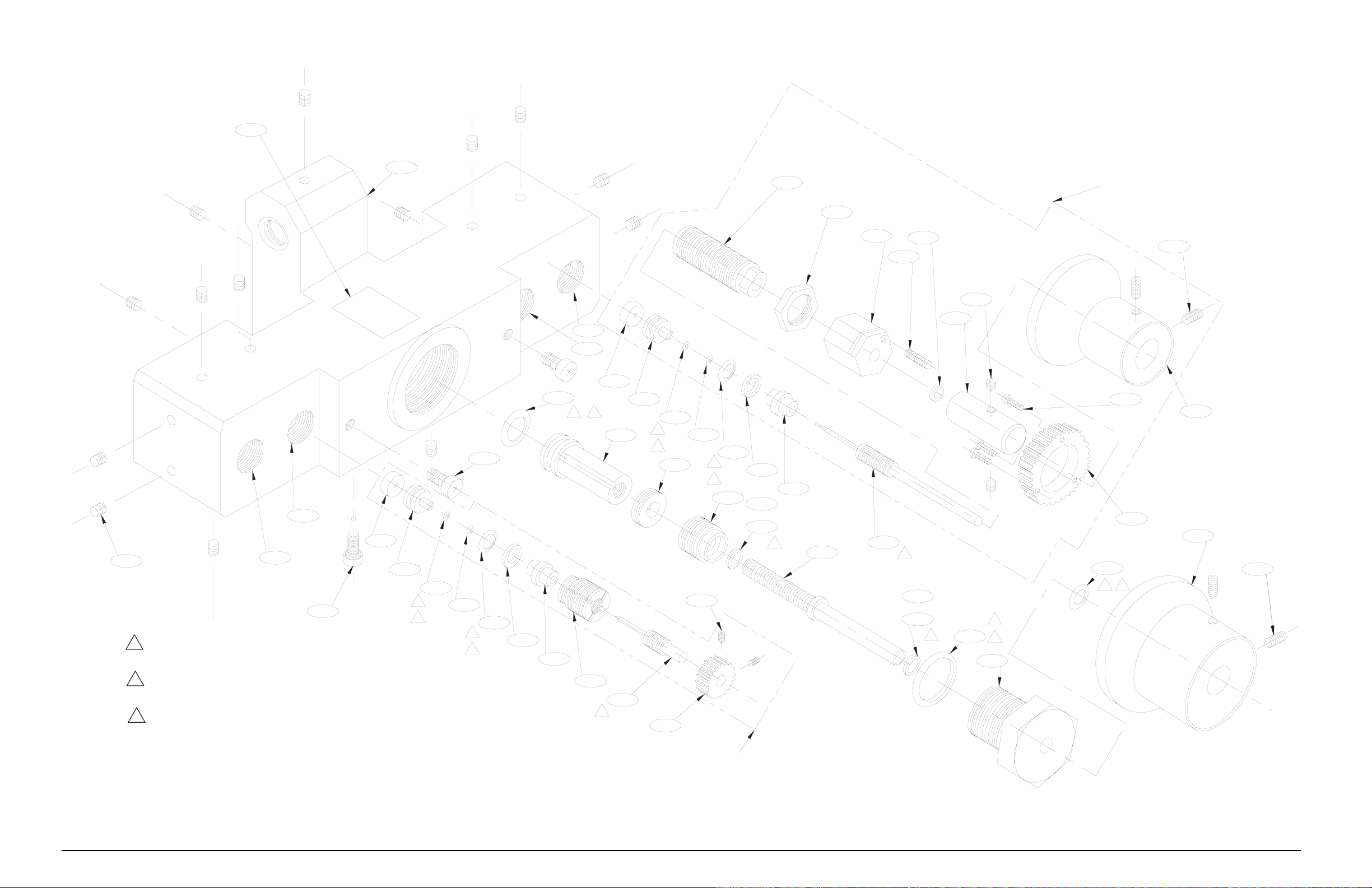
38
21/14X
A
NOTES:
LIGHTLY COAT THE FOLLOWING WITH LUBRICANT, PN 55593
1
O-RINGS, ITEMS 27, 28, 29 & 32.
THREADS ON VALVE NEEDLES, ITEMS 11 & 18.
ITEMS 41 & 42 QUANTITY AND USAGE TO BE SELECTED
2
DEPENDENT ON FIT, SEE VERNIER CONTROL REASSEMBLY
IN MANUAL.
FOR REFERENCE ONLY:
3
O-RING, ITEM 27, .239 ID
O-RING, ITEM 28, .042 ID
O-RING, ITEM 29, .799 ID
O-RING, ITEM 32, .424 ID
16
10
1
2
D
C
7
32
1
3
35/2X
B
7
9
28
36
1
3
31
27
1
3
30
8
19
1
9
28
15
18
1
3
6
31
27
26/2X
1
3
12
30
8
41
OR
42
2
14
11
20
33
34
23/2X
4
1
41
OR
42
2
1
29
3
13
THESE COMPONENTS TO BE INSTALLED
AT LOCATIONS A & D
25/2X
24/3X
3
5
17
27
1
3
25/2X
THESE COMPONENTS TO BE INSTALLED AT LOCATIONS B & C
Figure 7-1. ORION-2C Exploded View
DLR3110 Rack Mount Digital Pressure Calibrator Manual 55
Page 60

DLR3110 Rack Mount Digital Pressure Calibrator Manual 56
Page 61
7.4 ORION-3A Valve Assembly Parts List
Ref Number PN Description Quantity
1 57482 Valve needle housing nut 2
2 54401 Locknut 2
3 58079 Knob 2
4 57889 Insert knob 2
5 57256 Spur 40 tooth gear 2
6 59233 Spur 18-tooth gear 2
7 55896 Valve seat 4
8 59387 Stem valve seat 4
9 59045 Needle seat valve 4
10 54540 Valve needle housing 2
11 59551 Valve needle 2
12 57600 End bushing 1
13 58554 End cap 1
14 58699 Shaft 1
15 58597 Piston 1
16 59309 Dual valve body 1
17 57580 Knob 1
18 55533 Valve needle 2
19 55159 Valve needle housing 2
20 56784 Locknut,9/16-18UNF-3A, SST 1
21 58464 Setscrew,12-24NCx1/4 SST 14
22 58308 Tungsten carbide ball 14
23 59383 Setscrew,6-32NCx1/8 SST 4
24 58342 Screw,Cap Hex Socket Head, #2-56UNC-3A 6
25 59322 Setscrew,6-32NCx1/4 SST 6
26 59326 Setscrew,2-56NCx1/8, alloy steel 4
27 55569 O-ring, Fluorocarbon (Viton) color black w/white dot 5
28 55552 O-ring, Fluorocarbon (Viton) color black w/white dot 4
29 58090 O-ring, Fluorocarbon (Viton) color black w/white dot 1
30 60633 Packing backup retainer 4
31 55570 Backing washer 4
32 58045 O-ring, Fluorocarbon (Viton) color black w/white dot 1
33 59245 Nylon washer 2
34 60202 Hex setscrew 2
35 60837 Screw, MACH #10- 32NF SST 2
36 54905 Self sealing screw 1
38 57027 Backup washer 1
39 54448 Packing backup retainer 1
40 55615 O-ring, Fluorocarbon (Viton) color black w/white dot 1
41 58314 Ball, chrome, steel 32
42 59731 Male connector, 1/8 tube x 1/8 NPT, stainless steel 3
Table 7-4. ORION 3-A Valve Assembly Parts List
DLR3110 Rack Mount Digital Pressure Calibrator Manual 57
Page 62

58 Maintenance and Service
Page 63
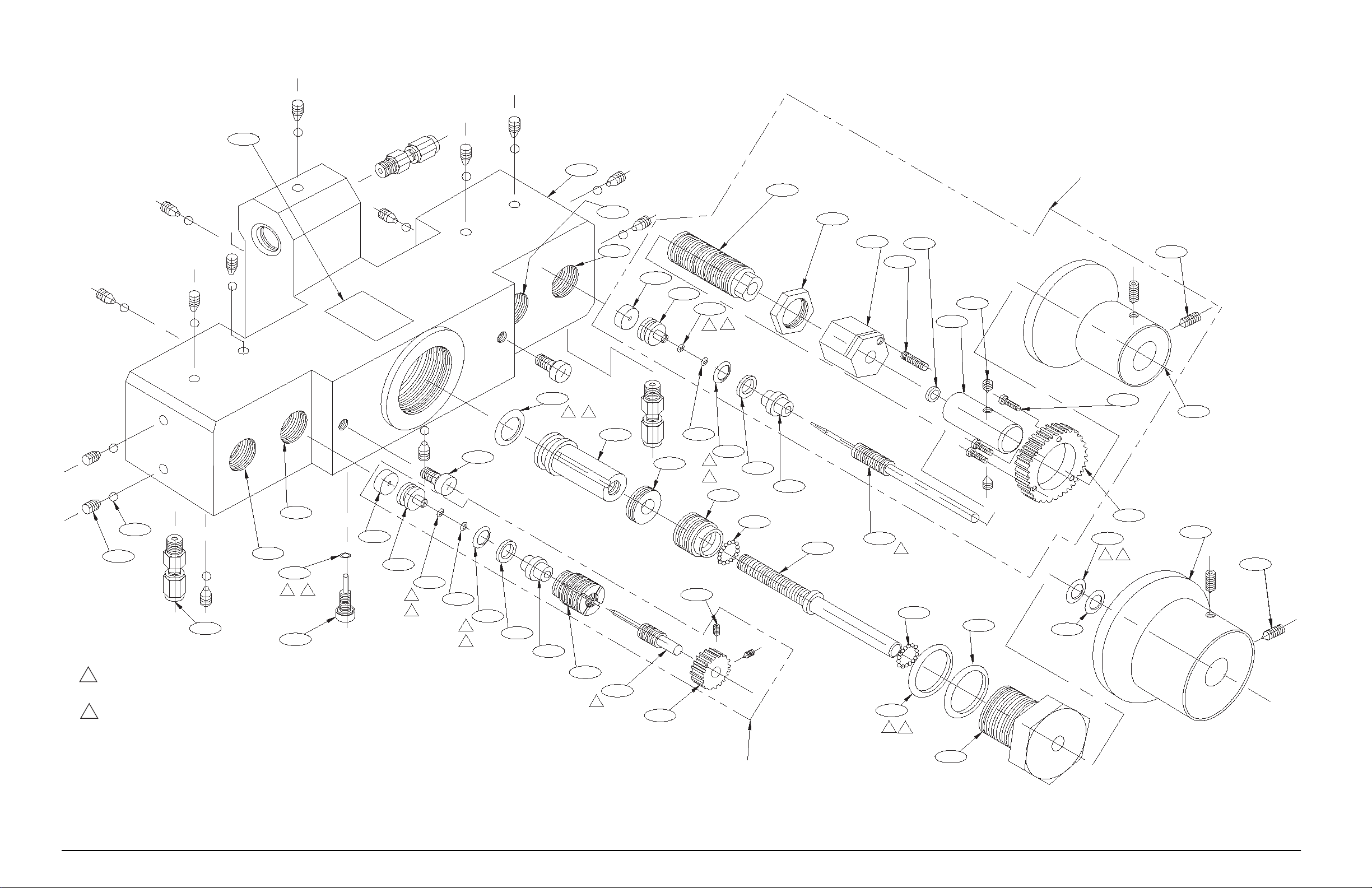
43
22/14X
21/14X
42/3X
NOTES:
LIGHTLY COAT THE FOLLOWING WITH LUBRICANT, PN 55593
1
O-RINGS, ITEMS 27, 28, 29, 32 & 40.
THREADS ON VALVE NEEDLES, ITEMS 11 & 18.
FOR REFERENCE ONLY:
2
O-RING, ITEM 27, .239 ID
O-RING, ITEM 28, .042 ID
O-RING, ITEM 29, .799 ID
O-RING, ITEM 32, .424 ID
O-RING, ITEM 40, .145 ID
16
10
C
D
7
9
28
2
1
32
1
2
15
35/2X
B
7
A
40
2
1
36
9
28
1
2
31
27
1
2
30
8
19
18
1
6
31
27
20
1
2
12
26/2X
THESE COMPONENTS TO BE INSTALLED
AT LOCATIONS B & C
30
8
41/16X
1
2
11
14
33
34
23/2X
4
1
41/16X
38
29
1
2
13
THESE COMPONENTS TO BE INSTALLED
AT LOCATIONS A & D
25/2X
24/3X
5
27
1
2
39
3
17
25/2X
Figure 7-2. ORION-3A Exploded View
DLR3110 Rack Mount Digital Pressure Calibrator Manual 59
Page 64

DLR3110 Rack Mount Digital Pressure Calibrator Manual 60
Page 65
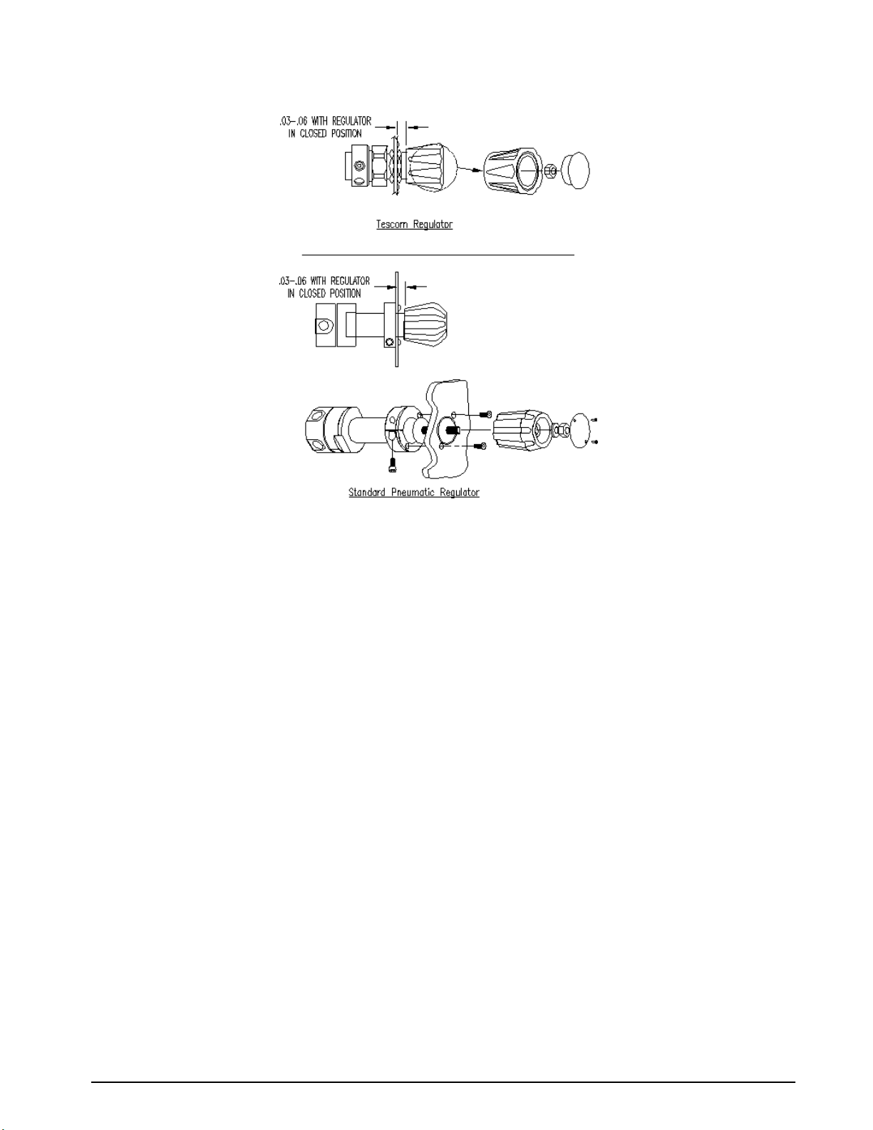
Figure 7-3. Tescom and Standard Pneumatic Regulator Mounting
Maintenance and Service 61
Page 66

8.0 Model Numbering System
DLR3110 - ____ ____ ____ ____ ____
≠ ≠ ≠ ≠ ≠
+-----------------------------+ ≠ ≠ ≠ ≠
≠ MOUNTING
≠ ≠ ≠ ≠ ≠
A - 19 in. Rack Mount ≠ ≠ ≠ ≠
≠ ≠ ≠ ≠
+-------------------------------------+ ≠ ≠ ≠
≠ POWER REQUIREMENTS
A - 120 VAC Operation ≠ ≠ ≠
D - 220 VAC Operation ≠≠ ≠
≠ ≠ ≠
+----------------------------------------------+ ≠ ≠
≠ PRESSURE RANGE
≠ ≠ ≠
A - 0-3 PSIG K - 0-2500 PSIG N - 0-15 PSIA ≠ ≠
B - 0-10 PSIG L - 0-5000 PSIG P - 0-25 PSIA ≠ ≠
C - 0-15 PSIG M - 0-10000 PSIG R - 0-50 PSIA ≠ ≠
D - 0-25 PSIG S - 0-100 PSIA ≠ ≠
E - 0-50 PSIG T - 0-250 PSIA ≠ ≠
F - 0-100 PSIG V - 0-500 PSIA ≠ ≠
G - 0-250 PSIG W - 0-1000 PSIA ≠ ≠
H - 0-500 PSIG Y - 0-2500 PSIA ≠ ≠
J - 0-1000 PSIG Z - 0-10000 PSIA ≠ ≠
≠ ≠
+------------------------------------------------------+ ≠
≠ ACCURACY
≠ ≠
A - 0.05% Indicated value from 20% of full scale ≠
B - 0.1% Indicated value from 20% of full scale ≠
C - 0.25% Indicated value from 20% of full scale ≠
≠
+---------------------------------------------------------------+
≠ OPTIONS
≠
A – Standard unit which includes, multiple conversion units, min/max,
freeze mode, RS232, RS422 and RS485
B – Standard unit plus two Relays and Setpoints option
C - Standard unit plus selectable scalable analog output
0-5VDC, 1-6VDC, 0-10VDC, 0-20mA, and 4-20mA
D - Standard unit plus parallel BCD output
NOTE: DLR3110 is available with test port on back of chassis.
≠ ≠ ≠ ≠
≠ ≠≠
≠ ≠≠
≠ ≠
≠
62 DLR3110 Rack Mount Digital Pressure Calibrator Manual
Page 67
9.0 Auto Selection Default Tables
Auto Selection (Gage) Default Table
Parameter 3 PSIG 10 PSIG 15 PSIG 25 PSIG 50 PSIG 100 PSIG 250 PSIG 500 PSIG
CAPACITY 3 10 15 25 50 100 250 500
CT-BY 0.0005 0.001 0.002 0.002 0.005 0.01 0.02 0.05
UNITS (Cal) PSI PSI PSI PSI PSI PSI PSI PSI
TYPE GAGE GAGE GAGE GAGE GAGE GAGE GAGE GAGE
CAL SPAN 1 0.3 1 1.5 2.5 5 10 25 50
CAL SPAN 2 0.6 2 3.0 5.0 10 20 50 100
CAL SPAN 3 0.9 3 4.5 7.5 15 30 75 150
CAL SPAN 4 1.2 4 6.0 10.0 20 40 100 200
CAL SPAN 5 1.5 5 7.5 12.5 25 50 125 250
CAL SPAN 6 1.8 6 9.0 15.0 30 60 150 300
CAL SPAN 7 2.1 7 10.5 17.5 35 70 175 350
CAL SPAN 8 2.4 8 12 20.5 40 80 200 400
CAL SPAN 9 2.7 9 13.5 22.5 45 90 225 450
CAL SPAN 10 3.0 10 15 25.0 50 100 250 500
HYSTERESIS 1.5 5 7.5 12.5 25 50 125 250
FILTR 55555555
DSP/SEC 33333333
ZERO % 22222222
ZERO+/-% 1.0 1.0 1.0 1.0 1.0 1.0 1.0 1.0
AZM +/- 0.5 0.5 0.5 0.5 0.5 0.5 0.5 0.5
MOTION 11111111
MIN PRES OFF OFF OFF OFF OFF OFF OFF OFF
MAX PRES OFF OFF OFF OFF OFF OFF OFF OFF
PSI ON ON ON ON ON ON ON ON
KPa ON ON ON ON ON ON ON ON
•
mmHg0
C
BAR OFF OFF OFF OFF OFF ON ON ON
•
C
inHg0
mBAR ON ON ON ON ON ON ON ON
0
cmH
2
2
kg/cm
060•F
inH
2
inH
04•C
2
ftseaH
0
2
TORR ON ON ON ON ON ON ON ON
metrsH
0
2
PASCAL ON ON ON ON ON OFF OFF OFF
04ºC
mmH
2
ON ON ON ON ON ON ON ON
ON ON ON ON ON ON ON ON
ON ON ON ON ON ON ON ON
OFF OFF OFF OFF OFF ON ON ON
ON ON ON ON ON ON ON ON
ON ON ON ON ON ON ON ON
ON ON ON ON ON ON ON ON
ON ON ON ON ON ON ON ON
ON ON ON ON ON ON ON ON
Table 9-1. Auto Selection (Gage) Default Table (3 PSIG – 500 PSIG)
Auto Selection Default Tables 63
Page 68
PARAMETER 1000 PSIG 2500 PSIG 5000 PSIG 10000 PSIG
CAPACITY 1000 2500 5000 10000
CT-BY 0.1 0.2 0.5 1
UNITS (CAL) PSI PSI PSI PSI
TYPE GAGE GAGE GAGE GAGE
CAL SPAN 1 100 250 500 1000
CAL SPAN 2 200 500 1000 2000
CAL SPAN 3 300 750 1500 3000
CAL SPAN 4 400 1000 2000 4000
CAL SPAN 5 500 1250 2500 5000
CAL SPAN 6 600 1500 3000 6000
CAL SPAN 7 700 1750 3500 7000
CAL SPAN 8 800 2000 4000 8000
CAL SPAN 9 900 2250 4500 9000
CAL SPAN 10 1000 5000 5000 10000
HYSTERESIS 500 1250 2500 5000
FILTR 5 5 5 5
DSP/SEC 3 3 3 3
ZERO % 2 2 2 2
ZERO+/-% 1.0 1.0 1.0 1.0
AZM +/- 0.5 0.5 0.5 0.5
MOTION 1 1 1 1
MIN PRES OFF OFF OFF OFF
MAX PRES OFF OFF OFF OFF
PSI ON ON ON ON
KPa ON ON ON ON
mmHg0
•
C
ON ON ON ON
BAR OFF OFF OFF OFF
inHg0•C
ON ON ON ON
mBAR ON ON ON ON
0
cmH
kg/cm
inH
060•F
2
inH
04•C
2
ftseaH20
2
2
ON ON ON ON
ON ON ON ON
ON ON ON ON
ON ON ON ON
ON ON ON ON
TORR ON ON ON ON
metrsH
0
2
ON ON ON ON
PASCAL OFF OFF OFF OFF
mmH
04•C
2
OFF OFF OFF OFF
Table 9-2. Auto Selection (Gage) Default Table (1000 PSIG – 10000 PSIG)
64 DLR3110 Rack Mount Digital Pressure Calibrator Manual
Page 69
Auto Selection (Absolute) Default Table
PARAMETER
15
PSIA
25
PSIA
50
PSIA
100
PSIA
250
PSIA
500
PSIA
1000
PSIA
2500
PSIA
10000
PSIA
CAPACITY 15 25 50 100 250 500 1000 2500 10000
CT-BY 0.002 0.002 0.005 0.01 0.02 0..05 0.1 0.2 1
UNITS (CAL) PSI PSI PSI PSI PSI PSI PSI PSI PSI
TYPE ABS ABS ABS ABS ABS ABS ABS ABS ABS
CAL SPAN 1 REF
0.5 0.5 0.5 0.5 0.5 0.5 1 1 1
CAL SPAN 2 1.5 2.5 5 10 25 50 100 250 1000
CAL SPAN 3 3.0 5.0 10 20 50 100 200 500 2000
CAL SPAN 4 4.5 7.5 15 30 75 150 300 750 3000
CAL SPAN 5 6.0 10.0 20 40 100 200 400 1000 4000
CAL SPAN 6 7.5 12.5 25 50 125 250 500 1250 5000
CAL SPAN 7 9.0 15.0 30 60 150 300 600 1500 6000
CAL SPAN 8 10.5 17.5 35 70 175 350 700 1750 7000
CAL SPAN 9 12.0 20 40 80 200 400 800 2000 8000
CAL SPAN 10 15.0 25 50 100 250 500 1000 2500 10000
HYSTERESIS 7.5 12.5 25 50 125 250 500 1250 5000
FILTR 555555555
DSP/SEC 333333333
ZERO % 222222222
ZERO+/-% 1.0 1.0 1.0 1.0 1.0 1.0 1.0 1.0 1.0
AZM +/- 0.5 0.5 0.5 0.5 0.5 0.5 0.5 0.5 0.5
MOTION 111111111
MIN PRES OFF OFF OFF OFF OFF OFF OFF OFF OFF
MAX PRES OFF OFF OFF OFF OFF OFF OFF OFF OFF
PSI ON ON ON ON ON ON ON ON ON
KPa ON ON ON ON ON ON ON ON ON
mmHg0
•
C
ON ON ON ON ON ON ON ON ON
BAR OFF OFF OFF ON ON ON ON ON ON
inHg0•C
ON ON ON ON ON ON ON ON ON
mBAR ON ON ON ON ON ON ON ON ON
0
cmH
kg/cm
060•F
inH
2
inH
04•C
2
ftseaH20
2
2
ON ON ON ON ON ON ON ON ON
OFF OFF OFF ON ON ON ON ON ON
ON ON ON ON ON ON ON ON ON
ON ON ON ON ON ON ON ON ON
ON ON ON ON ON ON ON ON ON
TORR ON ON ON ON ON ON ON ON ON
metrsH
0
2
ON ON ON ON ON ON ON ON ON
PASCAL ON ON ON OFF OFF OFF OFF OFF OFF
mmH
04•C
2
ON ON ON ON ON ON OFF OFF OFF
Table 9-3. Auto Selection (Absolute) Default Table
Auto Selection Default Tables 65
Page 70
10.0 Conversion Factors
Conversion
Conversion Factor
(PSI x )
Conversion Factor
(PSI x )
PSI 1 1.000000e+00
Kpa 6.894757 6.894757e+00
mmHg 0
•
C
51.7149 5.171490e+01
BAR 0.06894757 6.894757e-02
inHg 0
•
C
2.0360 2.036000e+00
mBAR 68.94757 6.894757e+01
cmH
0 70.308 7.030800e+01
2
2
Kg/cm
inH
O 60•F
2
inH2O 68•F
inH
O 4•C
2
ftseaH
O 2.252 2.252000e+00
2
0.070308 7.030800e-02
27.71 2.771000e+01
27.729 2.772900e+01
27.68 2.768000e+01
TORR 51.7149 5.171490e+01
metrsH
O 0.7030696 7.030696e-01
2
PACAL 6894.757 6.894757e+03
mmH
O 4•C
2
703.07 7.030700e+02
Table 10-1. Conversion Factors
66 DLR3110 Rack Mount Digital Pressure Calibrator Manual
Page 71

11.0 Options, Replacement Kits
There are numerous replacement part numbers mentioned throughout manual that may be ordered.
ORION-2C and ORION-3A O-Ring Replacement Kit (data sheet # 65308)
• Fluorocarbon “Viton” (standard for ORION-3A)...........................................PN 55277
•Nitrile Buna-N (standard for ORION-2C)......................................................PN 58499
• Ethylene-Propylene.........................................................................................PN 58506
• Silicone ...........................................................................................................PN 58509
•Neoprene.........................................................................................................PN 58515
NOTE: A small coating of fluorinated Krytox grease, (PN 55593), should be applied to both sides of O-ring prior
to installation.
• Pressure Trap
100 PSI full scale ranges and below (data sheet # 58621) .............................PN 58487
250, 500, 1000 or 2500 PSI full scale range (data sheet # 58609) .................PN 58483
5000 or 10000 PSI full scale range (data sheet # 58596) ...............................PN 58478
•Test Port (output) quick-disconnect male hose fitting
100 PSI full scale ranges and below ..............................................................PN 60195
250, 500, 1000 or 2500 PSI full scale range...................................................PN 55394
5000 or 10000 PSI full scale range.................................................................PN 55542
Test Port (output) hose, with quick-disconnect male fitting:
• 100 PSI full scale ranges and below 5’ long...................................................PN 60195, 55251 (1 each)
• 250, 500, 1000 or 2500 PSI full scale range 5' long ......................................PN 55279
• 250, 500, 1000 or 2500 PSI full scale range 10' long .....................................PN 55300
• 250, 500, 1000 or 2500 PSI full scale range 15' long .....................................PN 55304
• 250, 500, 1000 or 2500 PSI full scale range 20' long .....................................PN 55310
• 5000 or 10000 PSI full scale range 5' long ....................................................PN 55280
NOTE: Model may be ordered with Test Port mounted on rear of unit for additional charge.
Options, Replacement Kits 67
Page 72

12.0 Specifications
Pressure Specifications:
Pressure range: See Section 8.0 on page 62 for
available ranges
Available pressure
calibrations: Gage only or Absolute only
Overall accuracy: 0.05% of reading, or 0.1% of reading,
or 0.25% of reading all from 20% of
full scale and above. Includes all
effects of linearity, hysteresis,
repeatability and ambient temperature.
Accuracy statement includes all
effects of linearity, hysteresis,
repeatability and ambient temperature
Operating Temperature:+40° to +140°F (+4.4° to +6 0.0° C)
Storage Temperature: 0° to +185° F (–17.8° to +85°C)
Pressure Media: Any clean dry gas compatible with
17-4PH stainless steel
*Pressure Limit Gage:
Size: 2-in. diameter
Range: Based on model
Test Pressure: 1.5 times range
Pressure Media Filter:
Rating: 20 microns, Test Port, Input Port
Type: Field replaceable
Vent and Input Port:
Style: 1/4" 37° AN male
Pressure Rating: Based on model
Material: Brass or Stainless Steel
Pressure Hoses:
Quantity Supplied: One output
*Pressure Limit Control Regulator:
Type: Single stage, self-venting, non-bleed
Pressure Rating: 3000 PSIG max. inlet
Internal Pressure Sensor:
Type: Bonded, metal foil strain gage,
sputtered thin-film or equivalent.
Sensitivity: 30 mVfs
Construction: Completely weld-sealed stainless steel
outer body and pressure cavity
Physical Specifications:
Weight: 19 lbs. including all hoses and cables
Color: Dark tan
Case Dim’s: 19" wide x 9" deep x 7" high
(Case dimensions excluding front handles)
Orion Control Valve:
Type: Micro-metering with replaceable soft
seat
Material: Orion-2C: Aluminum body
Orion-3A: Stainless Steel body
Clear anodized
Aluminum knobs, black anodized
All other parts 300 series stainless
steel
*Over-pressure Rupture Disk:
Rating: 3000 PSIG, nominal
Type: Stainless steel outer case
*Relief Valve:
Type: Adjustable, atmospheric bleed
Setting: Adjustable to 10% above highest
calibrated pressure
Material: 300 series stainless steel
*Not required on 5000 or 10000 PSI models.
68 DLR3110 Rack Mount Digital Pressure Calibrator Manual
Page 73

DLR3110 Warranty and Return Policy
If possible, please save original packing material, which is specifically designed for the unit. Should it be
necessary to ship the unit back to the factory, a suitable shipping container must be used along with sufficient
packing material. Do not put a shipping label on the unit as a "suitable shipping container." Some units ha v e been
severely damaged this way. This is a delicate, precision instrument. Any damage incurred because of poor
packaging procedures will ultimately result in added service charges and longer turn-around times.
Vent all pressure lines before shipping.
Warning
When factory service is required, send only the unit in for repair. Retain fittings, manuals, etc. at your facility.
However, if there is a problem with a particular part, send in that part with the unit.
If a unit is found to be defective, it may be returned to our repair facility at the following address:
CONDEC
3 SIMM LANE
DOOR D, UNIT 2A
NEWTOWN, CT 06470
ATTN: PRESSURE PRODUCTS/REPAIR LAB
Each unit's I.D. plate is stamped with a date code (week/year) prior to shipment. Our warranty is twelve (12)
months from that date code and includes repair and/or replacement of the unit at our, Newtown facilities at no
charge. Units subjected to abuse or damaged by external influences, are not covered under warranty.
If the unit is found to be out of warranty, an evaluation charge of not less than fifty (U.S.) dollars ($50.00) will be
charged. Please note on any attached paperwork if a repair estimate is required or if there are any other specific
instructions.
Please be explicit as to the nature of the problem and/or its symptoms. Your documentation will save needless
time and expense. Also, please include a return shipping address (with a street address) and a contact name with
fax and telephone numbers. Contact numbers are necessary to provide a job estimate and in case further
questions arise at the factory.
69
Page 74
DLR3110 Return Material Authorization Form
The repair lab is also equipped to do calibrations on our calibrators and pressure standards. Calibrations include
a certification and are traceable to NIST.
COMPANY NAME:
STREET:
CITY, STATE, ZIP:
TELEPHONE:
FAX:
CONTACT PERSON:
MODEL NUMBER:________________ SERIAL NUMBER: _______________________________
PROBLEM WITH UNIT (PLEASE BE SPECIFIC):
IS THIS A WARRANTY REPAIR? ( ) YES ( ) NO
SHIP TO Address:
COMPANY NAME:
STREET:
CITY, STATE, ZIP:
ATTN:
CONDEC • 3 SIMM LANE • DOOR D, UNIT 2A • NEWTOWN, CT 06470
ATTN: PRESSURE PRODUCTS/REPAIR LAB
TEL: 888-295-8475 • FAX: 203-364-1556 or 715-234-6967
WEB SITE: www.4condec.com
70 DLR3110 Rack Mount Digital Pressure Calibrator Manual
 Loading...