

Page 1

CONCEPTRONIC C150APRA2 ENGLISH
1
Conceptronic C150APRA2
Extended User Manual
Congratulations on the purchase of your
Conceptronic wireless ADSL modem router.
This user manual gives you a step-by-step explanation of how to install and use the Conceptronic
wireless ADSL modem router.
When you need more information or support for your product, we advise you to visit our Service &
Support website at www.conceptronic.net/support and select one of the following options:
FAQ : Frequently Asked Questions database
Downloads : Manuals, Drivers, Firmware and more downloads
Contact : Contact Conceptronic Support
For general information about Conceptronic products visit the Conceptronic website at
www.conceptronic.net.
The information in this quick installation guide is based on Windows 7 and Vista, but can differ from
your computer when you are using a different operating system.
Page 2

CONCEPTRONIC C150APRA2 ENGLISH
2
Table of contents
1. Introduction
1.1 Safety Precautions
1.2 Features
1.3 Package contents
2. The wireless ADSL modem router explained
2.1 Front panel
2.2 Back panel
3. Hardware Installation
3.1 DSL (Telephone) port
3.2 LAN port(s)
4. Configuring the computer
4.1 Configure your IP address
4.2 Checking your connection
5. Modem router configuration
5.1 Factory default settings
5.2 Web-based configuration
5.3 Setup
5.3.1 Setup - Wizard
5.3.2 Setup - Internet Setup
5.3.3 Setup - Wireless
5.3.3.1 Setup - Wireless - Wireless Basic
5.3.3.2 Setup - Wireless - Wireless Security
5.3.4 Setup - Local Network
5.3.5 Setup - Time and Date
5.3.6 Setup - Logout
5.4 Advanced
5.4.1 Advanced – Port Forwarding
5.4.2 Advanced – Advanced Wireless
5.4.2.1 Advanced – Advanced Wireless – Advanced Settings
5.4.2.2 Advanced – Advanced Wireless – MAC Filtering
5.4.2.3 Advanced – Advanced Wireless – Security Settings
5.4.2.4 Advanced – Advanced Wireless – WPS Settings
5.4.3 Advanced – DMZ
5.4.4 Advanced – Parental Control
5.4.4.1 Advanced – Parental Control - Block Website
5.4.4.2 Advanced – Parental Control – Block MAC Address
5.4.5 Advanced – Filtering Options
5.4.5.1 Advanced – Filtering Options – Inbound IP Filtering
5.4.5.2 Advanced – Filtering Options – Outbound IP Filtering
5.4.5.3 Advanced – Filtering Options – Bridge Filtering
5.4.6 Advanced – QOS Config
5.4.6.1 Advanced – QOS Config – QOS Interface Config
5.4.6.2 Advanced – QOS Config – QOS Queue Config
5.4.6.3 Advanced – QOS Config – QOS Classify Config
5.4.7 Advanced – Firewall Settings
5.4.8 Advanced – DNS
5.4.9 Advanced – Dynamic DNS
Page 3

CONCEPTRONIC C150APRA2 ENGLISH
3
5.4.10 Advanced – Network Tools
5.4.10.1 Advanced – Network Tools – Port Mapping
5.4.10.2 Advanced – Network Tools – IGMP Proxy
5.4.10.3 Advanced – Network Tools – IGMP Snooping
5.4.10.4 Advanced – Network Tools – UPnP
5.4.10.5 Advanced – Network Tools – ADSL
5.4.10.6 Advanced – Network Tools – SNMP
5.4.11 Advanced – Routing
5.4.11.1 Advanced – Routing – Static Routing
5.4.11.2 Advanced – Routing – Default Gateway
5.4.11.3 Advanced – Routing – RIP
5.4.12 Advanced – Schedules
5.4.13 Advanced – Logout
5.5 Management
5.5.1 Management – System Management
5.5.2 Management – Firmware Update
5.5.3 Management – Access Controls
5.5.3.1 Management – Access Controls – User Management
5.5.3.2 Management – Access Controls – Services
5.5.3.3 Management – Access Controls – IP Address
5.5.4 Management – Diagnosis
5.5.5 Management – Log Configuration
5.5.6 Management – Logout
5.6 Status
5.6.1 Status – Device Info
5.6.2 Status – Wireless Clients
5.6.3 Status – DHCP Clients
5.6.4 Status – Logs
5.6.5 Status – Statistics
5.6.6 Status – Route Info
5.6.7 Status – Logout
5.7 Help
6. Frequently Asked Questions
7. License Information
Page 4

CONCEPTRONIC C150APRA2 ENGLISH
4
1. Introduction
The C150APRA2 supports multiple line modes. It provides four 10/100 base-T Ethernet interfaces at
the user end. The device provides high speed ADSL broadband connection to the Internet or Intranet
for high-end users, such as net cafes and office users. It provides high performance access to the
Internet, downstream up to 24 Mbps and upstream up to 1 Mbps.
The device supports WLAN access. It can connect to the Internet through a WLAN AP or WLAN
device. It complies with IEEE 802.11, 802.11b/g specifications, WEP, WPA, and WPA2 security
specifications.
In the IEEE 802.11n mode, 1T1R can reach the maximum wireless transmission rate of 150 Mbps.
1.1 Safety Precautions
Refer to the following instructions to prevent the device from risks and damage caused by fire or
electric power:
Use volume labels to mark the type of power.
Use the power adapter packed within the device package.
Pay attention to the power load of the outlet or prolonged lines. An overburden power outlet or
damaged lines and plugs may cause electric shock or fire accident. Check the power cords
regularly. If you find any damage, replace the power cords at once.
Proper space left for heat dissipation is necessary to avoid damage caused by overheating to the
device. The long and thin holes on the device are designed for heat dissipation to ensure that the
device works normally. Do not cover these heat dissipation holes.
Do not put this device close to a place where a heat source exits or high temperature occurs.
Avoid the device from direct sunshine.
Do not put this device close to a place where it is over damp or watery. Do not spill any fluid on
this device.
Do not connect this device to any PCs or electronic products, unless our customer engineer or
your broadband provider instructs you to do this, because any wrong connection may cause power
or fire risk.
Do not place the device on an unstable surface or support.
Page 5

CONCEPTRONIC C150APRA2 ENGLISH
5
1.2 Features
The device supports the following features:
802.11b/g/n
Various line modes
External PPPoE dial-up access
Internal PPPoE and PPPoA dial-up access
1483 Bridged, 1483 Routed, and MER access
Multiple PVCs (up to eight) that can be isolated
from each other
A single PVC with multiple sessions
Multiple PVCs with multiple sessions
Binding of ports with PVCs
802.1Q
DHCP server
NAT and NAPT
Static routing
Firmware upgrade through Web or TFTP
Restore to the factory defaults
DNS
Virtual server
DMZ
Web user interface
Telnet CLI
System status displaying
PPP session PAP, CHAP, and MS-CHAP
IP filter
IP QoS
Remote access control
Line connection status test
Remote management through telnet or HTTP
Backup and restoration of configuration file
Ethernet interface supports crossover
detection, auto-correction and polarity
correction
UPnP
1.3 Package contents
The following items are present in the package of the Conceptronic wireless ADSL modem router:
Conceptronic wireless ADSL modem router (C150APRA2)
Antenna for wireless connections
Power supply 12V DC, 800mA
Network (LAN) cable
Phone cable (RJ-11)
Product CD-ROM
This multi language user manual
Warranty card & CE declaration booklet
Page 6

CONCEPTRONIC C150APRA2 ENGLISH
6
2. The wireless ADSL modem router explained
2.1 Front panel
Nr Description Status Status Explanation
A Power LED OFF Power is OFF
ON - GREEN Power is on and the initialization is normal
ON - RED Device is initiating
ON - FLASHING Firmware is upgrading
B ADSL LED OFF Initial self test failed
ON – FLASHING Device is detecting DSL signal
ON - STEADY DSL signal detected, self test succeeded
C Internet LED ON - Red No DSL connection
ON - Green Internet connection available
D LAN LEDs OFF LAN port is not connected
(1, 2, 3, 4) ON - STEADY A device is connected to the LAN port
ON - FLASHING Data is being transmitted
E WLAN LEDs OFF Wireless LAN is turned off
ON - STEADY Wireless LAN is active and normal
ON - FLASHING Wireless LAN activity (sending or receiving data)
F WPS LED OFF WPS (Wi-Fi Protected setup) not active
ON - FLASHING WPS active, new WLAN clients can be added
ON – STEADY WPS client successfully added
Page 7

CONCEPTRONIC C150APRA2 ENGLISH
7
2.2 Back panel
Nr Description Explanation
A Antenna connection Connect the included antenna to the modem router.
B DSL port Connect your ADSL line to the modem router.
C LAN ports (1 – 4) Connect your computer(s)/network device(s) to the modem router.
D Power connector Connect the power supply to the modem router.
E Reset Perform a factory reset (hold).
F WLAN / WPS button Short press (1 sec) : Turn WiFi on or off.
Long press (> 3 sec) : Start WPS Push Button configuration.
G Power button Turn the modem router on or off.
Page 8

CONCEPTRONIC C150APRA2 ENGLISH
8
3. Hardware Installation
Connect the included antenna to the antenna connection [A] on the back of the modem router.
Connect the power supply to the power connection [D] on the back of the modem router and to
an available wall socket.
Press the power [G] button on the back of the modem router.
The power LED on the front of the modem router will light up and the modem router will perform a
system startup.
3.1 DSL (Telephone) port
Most ADSL providers require a splitter between your phone line and the ADSL modem that prevents
the ADSL line from interfering with regular telephone services. Not using such a splitter could lead
to connection problems or bad performance.
Note: The C150APRA2 is not delivered with a splitter for the ADSL connection. Please contact your
telephone or internet provider for the correct ADSL splitter.
The connection ports of an ADSL splitter are typically labelled as following:
Line : This port connects to the wall jack
ADSL : This port connects to the router
Phone : This port connects to a telephone or other telephone device
Make sure the lines are properly connected. If you are unable to hear a dial tone with the
telephone, check the connections to make sure the cables are securely attached and connected to
the correct port.
Use a telephone cable to connect the Conceptronic wireless ADSL modem router (B) to your local
analog telephone line (or splitter). The ADSL led will light up when an ADSL signal has been
detected.
Note: If the ADSL LED on the front does not lit up, make sure that:
- The wireless ADSL modem router is powered on (the power LED should burn).
- There is an ADSL signal on the line.
- The Internet LED will only be green when correct DSL and user account settings are
applied into the Web Interface of the ADSL modem router.
3.2 LAN port(s)
Connect the network (LAN) cable to 1 of the 4 LAN ports on the back panel of the wireless ADSL
modem routerand to the network card of your computer.
The LAN LED of the used LAN port will lit up, indicating that the computer is connected. (Your
computer must be switched on and the LAN connection must be enabled).
Page 9
CONCEPTRONIC C150APRA2 ENGLISH
9
4. Configuring the computer
4.1 Configure your IP address
The C150APRA2 is equipped with a built-in DHCP server. The DHCP server will automatically assign
an IP address to each connected computer if the connected computer is set to ―Obtain an IP
address automatically‖.
By default most computers are configured to automatically obtain an IP address. When this is not
the case, you will need to configure your computer to obtain an IP address automatically by
following the instructions below. These instructions are based on Windows Vista with Service Pack
1. If your computer has a different version or operaring system, the steps required might be
different.
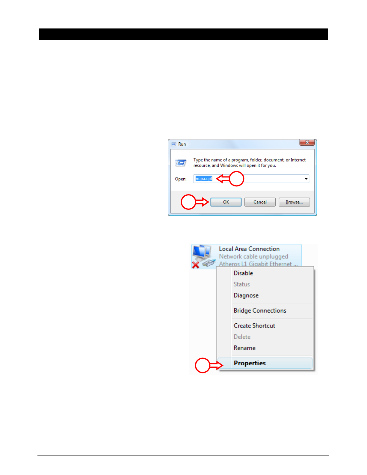
A. Click ―Start‖ ―Run‖.
B. Enter the command ―NCPA.CPL‖
and press ―OK‖.
The ―Network Connections‖ window will appear.
C. Right click your ―Local Area Connection‖
(wired or wireless, depending on the
connection you use) and select
―Properties‖.
B
B
C
Page 10
CONCEPTRONIC C150APRA2 ENGLISH
10
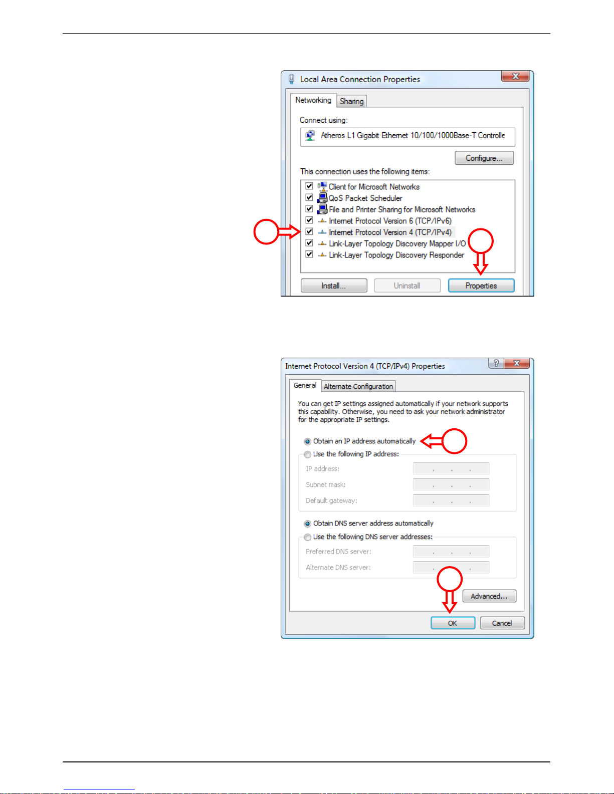
The Properties window of the Local Area Connection will appear.
D. Select the ―Internet Protocol
Version 4 (TCP/IPv4)‖ and click
―Properties‖.
The Properties window of the Internet Protocol Version 4 (TCP/IPv4) will appear.
E. Set the properties to ―Obtain an IP
address automatically‖ and press
―OK‖ to save the settings.
F. Press ―OK‖ in the properties
window of the Local Area
Connection to save the settings.
D D E
E
Page 11
CONCEPTRONIC C150APRA2 ENGLISH
11
4.2 Checking your connection
With the Command Prompt of Windows you can verify if you have received a correct IP address on
your (wired or wireless) Local Area Connection. This example is based on Windows Vista with
Service Pack 1. Windows Vista needs administrative rights to perform the steps below. There is an
explanation on how to gain administrative rights.
A. Click ―Start‖ ―All programs‖ ―Accessories‖, right click ―Command Prompt‖ and select
―Run as administrator‖. You might get a warning message, which you need to accept by
clicking ―Continue‖.
The Command Prompt will appear. Make sure the Command Prompt title bar mentions
―Administrator: Command Prompt‖. When ―Administrator‖ is not mentioned, you do not have the
needed administrative rights for these steps and you will need to perform step A again.
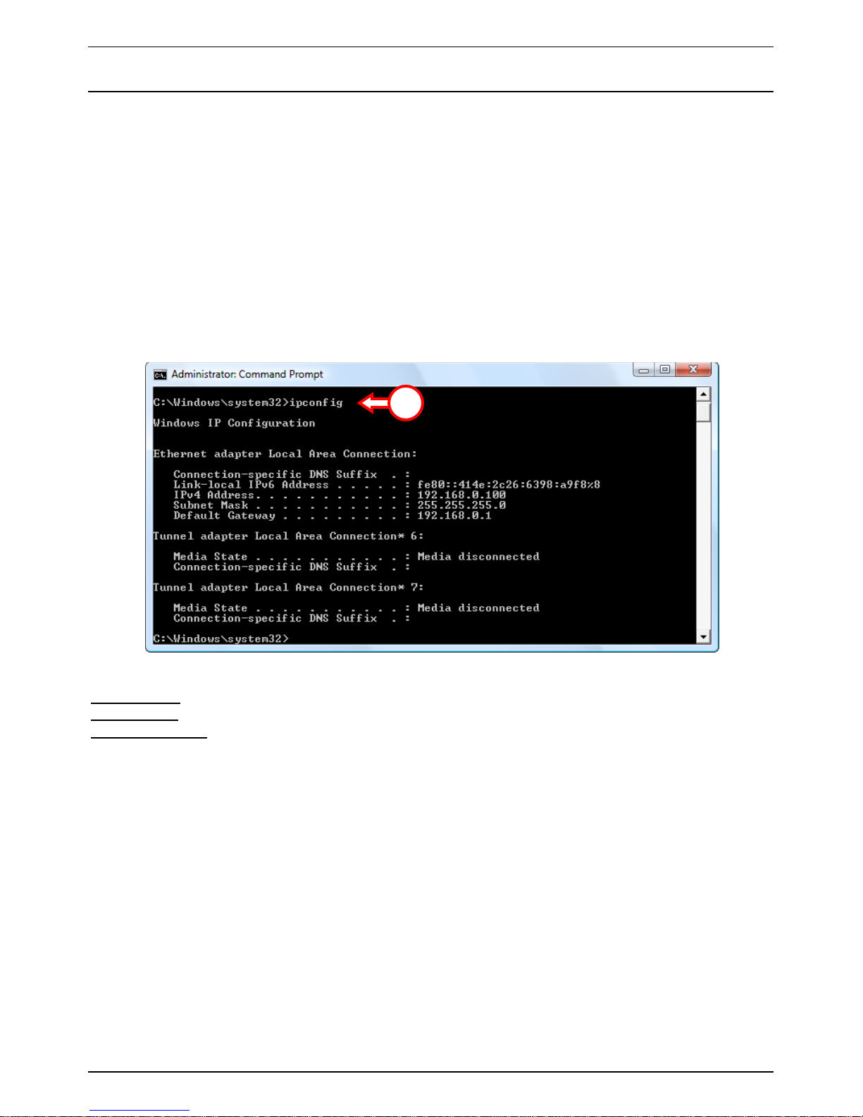
B. Enter the command ―IPCONFIG‖ and press ENTER.
You should see the following information
IPv4 Address : 192.168.0.xxx (Where xxx can vary between 100 ~ 199).
Subnet Mask : 255.255.255.0
Default Gateway : 192.168.0.1
If the information shown above matches your configuration you can continue the configuration of
the device in Chapter 5.
If the information shown above does not match your configuration (i.e. your IP address is
169.254.xxx.xxx) please check the options below:
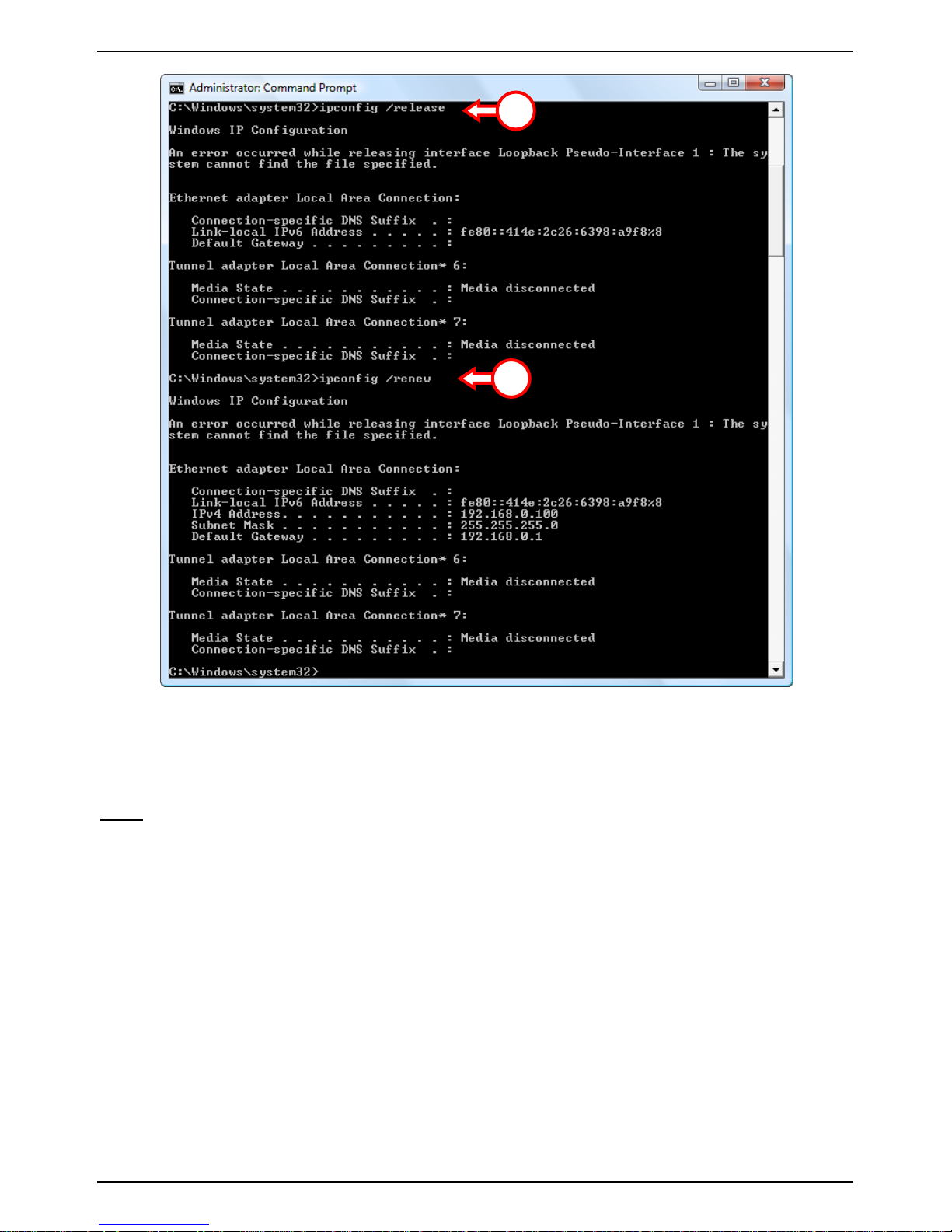
1. Power off and power on the device.
2. Reconnect the LAN cable to the device and to your computer.
3. Renew the IP address of your computer with the following commands:
- ―IPCONFIG /RELEASE‖ to release the incorrect IP address.
- ―IPCONFIG /RENEW‖ to receive a new IP address from the device.
B
Page 12
CONCEPTRONIC C150APRA2 ENGLISH
12
If above steps do not solve the IP address problem, you can reset the device to the factory default
settings with the Reset button on the back of the device.
Press and hold the Reset button for +/- 15 seconds to load the factory default settings. When the
Status LED is active again, repeat step B to renew your IP address.
Note: If the problem remains, check if all cables are connected correctly. The ADSL port should be
connected to the ADSL line and the LAN port to the computer.
3
3
Page 13

CONCEPTRONIC C150APRA2 ENGLISH
13
5. Modem router configuration
This chapter describes how to configure the C150APRA2 using the built-in Quick Start Wizard. After
completing the steps in this chapter your router has been set up for an ADSL connection and will be
able to connect to the internet.
5.1 Factory default settings
The C150APRA2 is preconfigured with several settings. The preconfigured settings can be found
below:
IP Address : 192.168.0.1 (DHCP Server for LAN/WLAN clients Enabled)
Username : admin (select this user)
Password : admin (small characters)
Wireless SSID : C150APRA2
Wireless Channel : Channel 6
Wireless Security : WPA2
UPnP : disabled (can be enabled when internet connection is configured)
When you have changed settings in the configuration of the C150APRA2, they will be saved to the
memory of the router. To restore the factory default settings, press and hold the reset button on
the back of the device for +/- 15 seconds.
5.2 Web-based configuration
The configuration of the C150APRA2 is web based. You will need a web browser for the
configuration of the device.
Note: For configuration of the router it is advised to use a LAN cable connection to the device
instead of a wireless connection.
A. Start your web browser (like: Internet Explorer, FireFox, Safari or Chrome).
B. Enter the IP address of the device in the address bar of your web browser (by default:
http://192.168.0.1/).
C. You will first get a login window asking you for a Username and Password. Select the user
―admin‖ from the dropdown list, enter the password for the administrator (default = ‗admin‘)
and click ―Login‖ to enter the web-based configuration.
Page 14

CONCEPTRONIC C150APRA2 ENGLISH
14
When the Username and Password are correct the router will display the ―overview‖ page:
The ―overview‖ page shows a quick menu for configuring and maintaining the C150APRA2.
Page 15
CONCEPTRONIC C150APRA2 ENGLISH
15
5.3 Setup
In the ―Setup‖ menu, you can configure the basic configuration for your modem router.
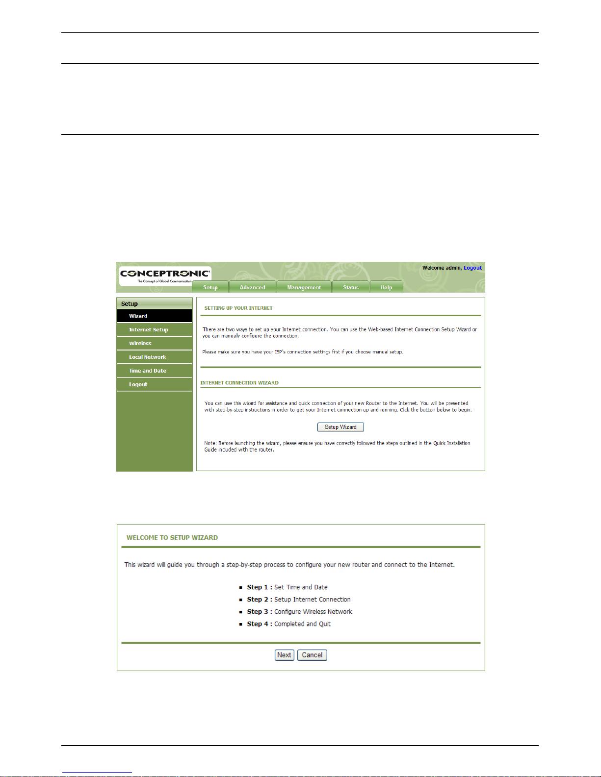
5.3.1 Setup - Wizard
Wizard helps you to fast and accurately configure Internet connection and other important
parameters. The following sections describe these various configuration parameters.
When subscribing to a broadband service, be aware of the Internect connection mode. The physical
WAN device can be Ethernet, DSL, or both. Technical information about properties of Internet
connection is provided by your Internet service provider (ISP). For example, your ISP should inform
you whether you are connected to the Internet using a static or dynamic IP address, and the
protocol, such as PPPoA or PPPoE, that you use to communicate on the Internet.
Step 1 Choose Setup > Wizard. The page as shown in the following figure appears:
Step 2 Click Setup Wizard. The page as shown in the following figure appears:
There are four steps to configure the device. Click Next to continue.
Page 16
CONCEPTRONIC C150APRA2 ENGLISH
16
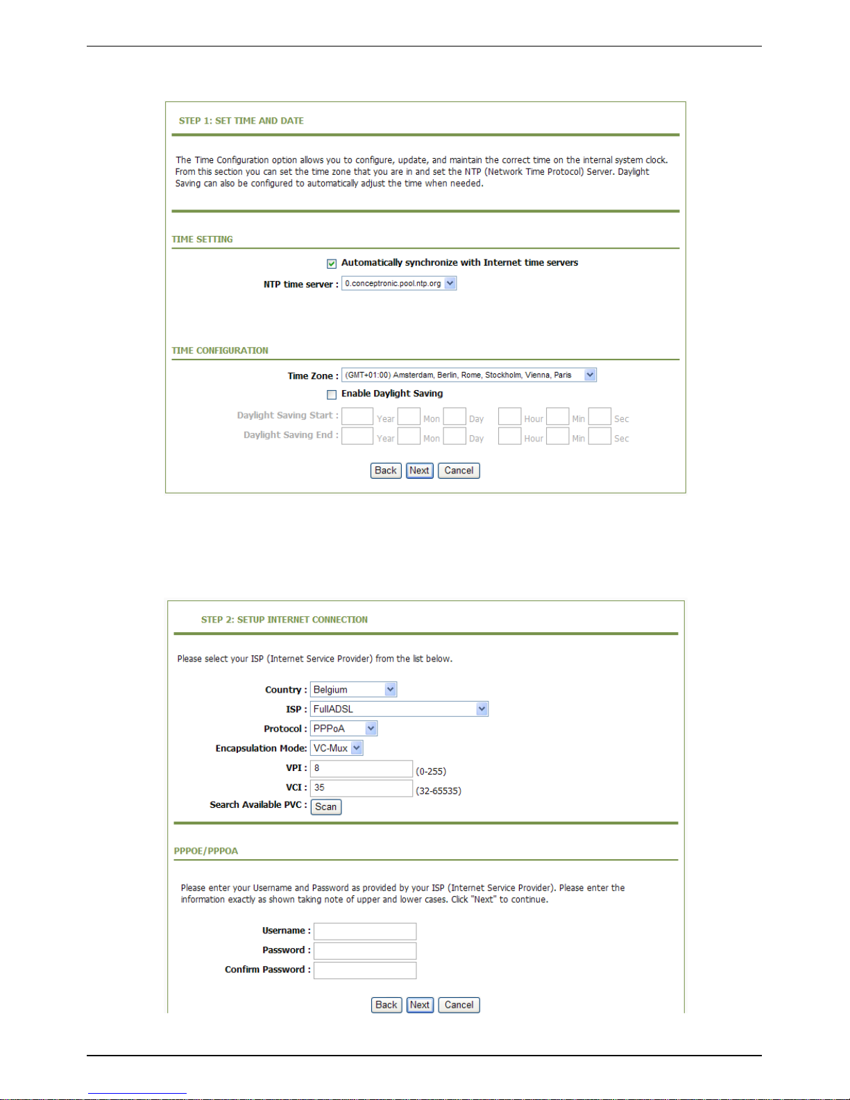
Step 3 Set the time and date. Then, click Next.
Step 4 Configure the Internet connection.
Select the country and ISP from the drop-down list. If the Country is set to Belgium, the
ISP is set to FullADSL, the Protocol is set to PPPoE or PPPoA, the page as shown in the
following figure appears:
You need to enter the user name and password for PPPoE or PPPoA dialup.
Page 17
CONCEPTRONIC C150APRA2 ENGLISH
17
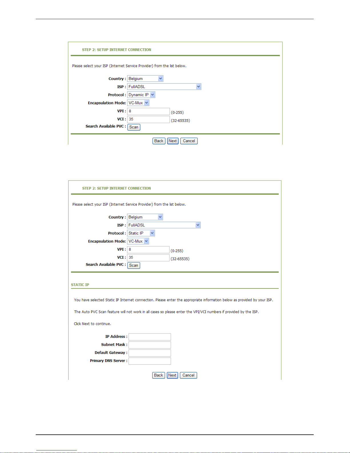
If the Protocol is set to Dynamic IP, the page as shown in the following figure appears:
If the Protocol is set to Static IP, the page as shown in the following figure appears:
You need to enter the information of the IP address, subnet mask, and gateway.
Page 18
CONCEPTRONIC C150APRA2 ENGLISH
18
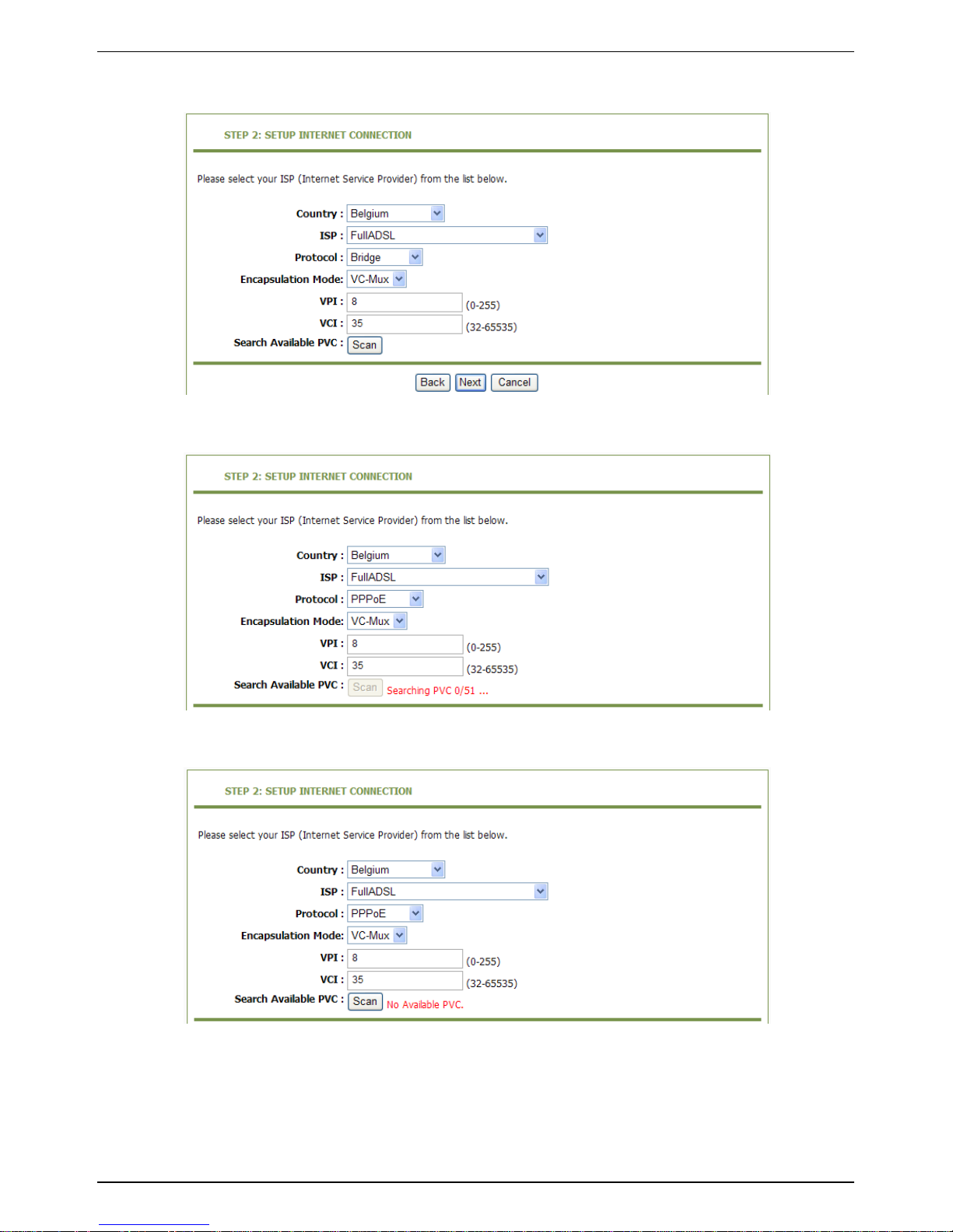
If the Protocol is set to Bridge, the page as shown in the following figure appears:
If you click Scan, the system automatically searches the available PVCs.
After the searching is complete, the result appears next to the Scan button.
After setting, click Next.
Page 19
CONCEPTRONIC C150APRA2 ENGLISH
19
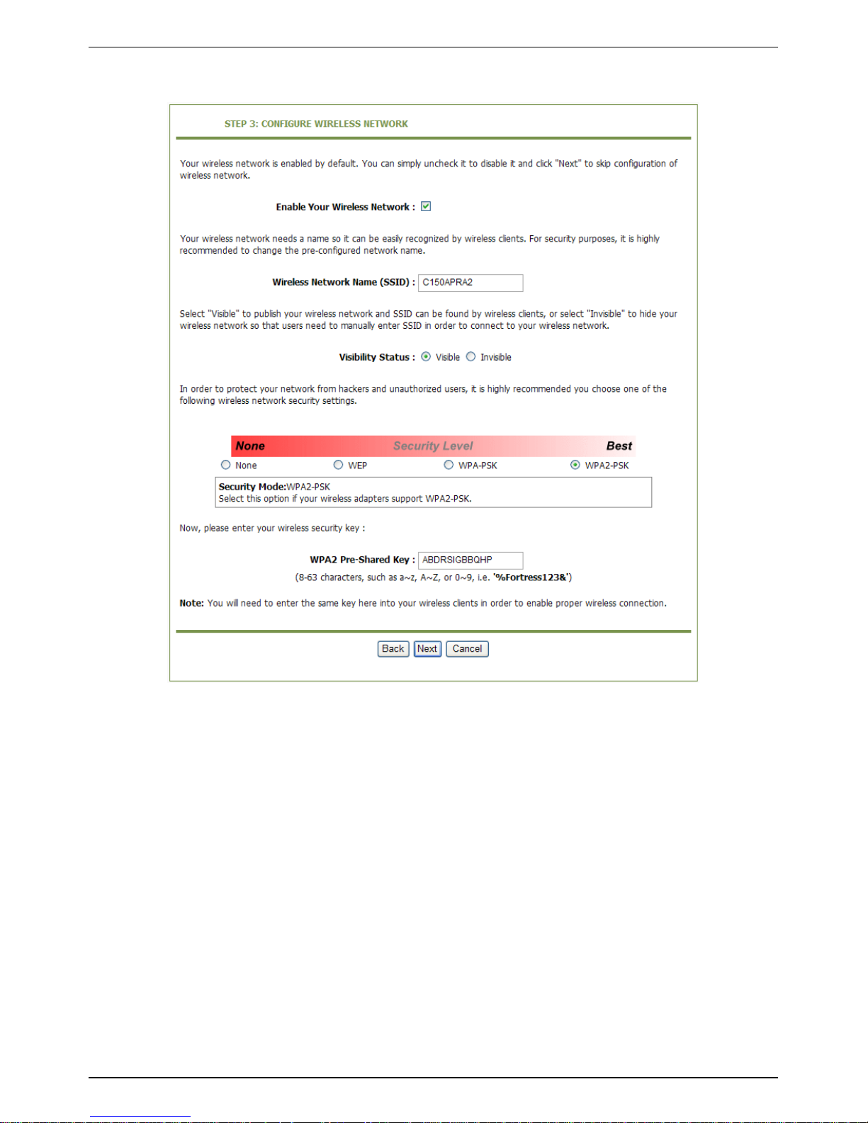
Step 5 Configure the wireless network. Enter the information and click Next.
Step 6 View the configuration information of the device. To modify the information, click Back.
To effect the configuration, click Apply.
Page 20

CONCEPTRONIC C150APRA2 ENGLISH
20
Note: In each step of the Wizard page, you can click Back to review or modify the previous
settings or click Cancel to exit the wizard.
Page 21

CONCEPTRONIC C150APRA2 ENGLISH
21
5.3.2 Setup - Internet Setup
Choose Setup > Internet Setup. The page as shown in the following figure appears:
In this page, you can configure the WAN interface of the device.
Click Add and the page as shown in the following figure appears:
Page 22

CONCEPTRONIC C150APRA2 ENGLISH
22
Page 23

CONCEPTRONIC C150APRA2 ENGLISH
23
The following table describes the parameters in this page.
ATM PVC CONFIGURATION
Field
Description
VPI
Virtual Path Identifier (VPI) is the virtual path between two points
in an ATM network. Its value range is from 0 to 255.
VCI
Virtual Channel Identifier (VCI) is the virtual channel between two
points in an ATM network. Its value range is from 32 to 65535 (0 to
31 is reserved for local management of ATM traffic).
Service Category
Select UBR with PCR, UBR without PCR, CBR, Non Realtime VBR,
or Realtime VBR from the drop-down list.
Peak Cell Rate
Set the maximum transmission rate of the cell in ATM transmission.
Sustainable Cell Rate
Set the minimum transmission rate of the cell in ATM transmission.
Maximum Burst Size
Set the maximum burst size of the cell in ATM transmission.
CONNECTION TYPE
Field
Description
Protocol
Select PPP over ATM (PPPoA), PPP over Ethernet (PPPoE), MAC
Encryption Routing (MER), IP over ATM (IPoA), or Bridging from
the drop-down list.
Encapsulation Mode
Select LLC or VCMUX from the drop-down list. Usually, you can
select LLC.
802.1Q VLAN ID
If you enter a value, packets from the interface is tagged with the
set 802.1q VLAN ID. Its value range is 0-4094, while 0 indicates to
disable this function.
NETWORK ADDRESS TRANSLATION SETTINGS
Field
Description
Enable Bridge Service
Select or deselect the check box to enable or disable the WAN
connection.
Service Name
The name to identify the WAN connection. You need not modify it.
Page 24
CONCEPTRONIC C150APRA2 ENGLISH
24
5.3.3 Setup - Wireless
This section describes the wireless LAN and some basic configuration. Wireless LANs can be as
simple as two computers with wireless LAN cards communicating in a pear-to-pear network or as
complex as a number of computers with wireless LAN cards communicating through access points
that bridge network traffic to a wired LAN.
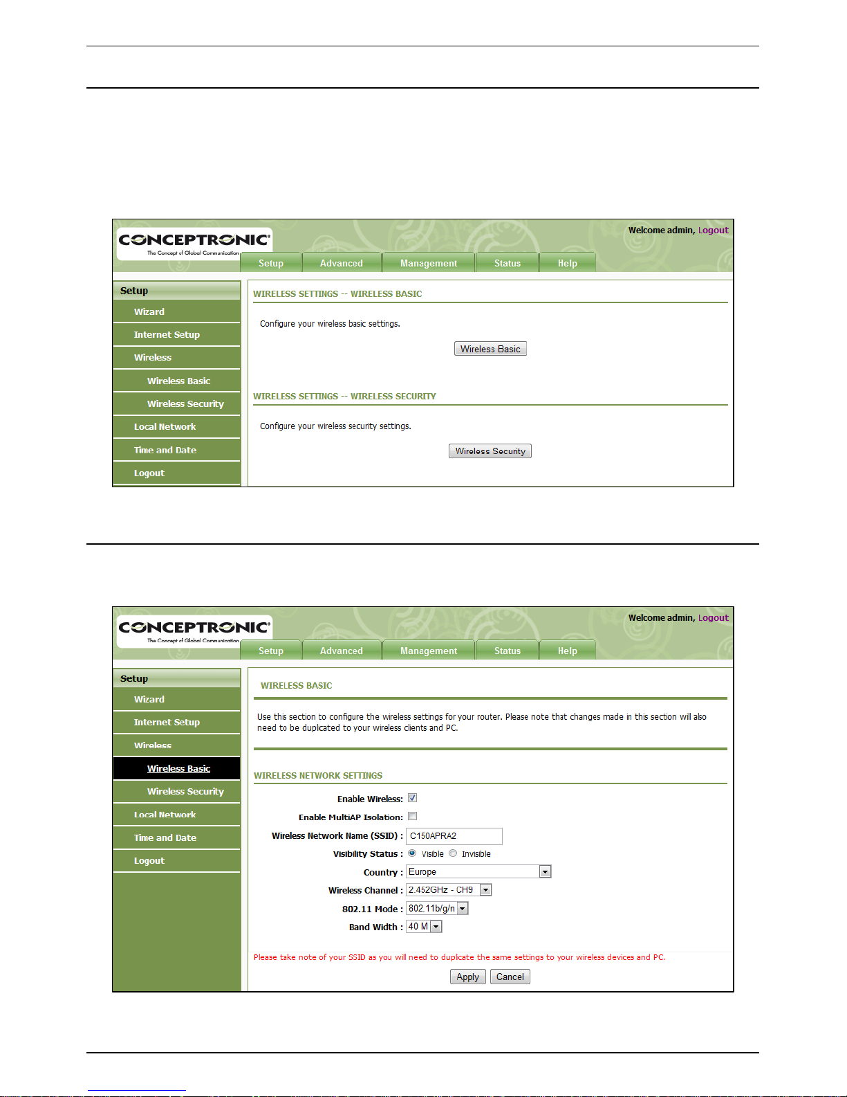
Choose Setup > Wireless. The WIRELESS SETTINGS page as shown in the following figure appears:
5.3.3.1 Setup – Wireless - Wireless Basic
In the WIRELESS SETTINGS page, click Wireless Basic. The page as shown in the following figure
appears:
In this page, you can configure the parameters of wireless LAN clients that may connect to the
device.
Page 25

CONCEPTRONIC C150APRA2 ENGLISH
25
The following table describes the parameters in this page.
Field
Description
Enable Wireless
Select or deselect the check box to enable or disable the wireless
function.
Enable MultiAP Isolation
Select or deselect the check box to enable or disable multiAP
isolation. If this function is enabled, clients of different SSIDs
cannot access each other.
Wireless Network Name
(SSID)
Network name. It can contain up to 32 characters. It can consist
of letters, numerals, and/or underlines.
Visibility Status
Visible indicates that the device broadcasts the SSID.
Invisible indicates that the device does not broadcast the
SSID.
Country
Select the country where you are in from the drop-down list.
Wireless Channel
Select the wireless channel used by the device from the dropdown list. You can select Auto Scan or a value from CH1—CH13.
Auto Scan is recommended.
802.11 Mode
Select the 802.11 mode of the device from the drop-down list.
The device supports 802.11b, 802.11g, 802.11n, 802.11b/g,
802.11n/g, and 802.11b/g/n.
Band Width
You can set the bandwidth only in the 802.11n mode. You can set
the bandwidth of the device to 20M or 40M.
Click Apply to save the settings.
Page 26
CONCEPTRONIC C150APRA2 ENGLISH
26
5.3.3.2 Setup – Wireless - Wireless Security
In the WIRELESS SETTINGS page, click Wireless Security. The page as shown in the following figure
appears:
Wireless security is vital to your network to protect the wireless communication among wireless
stations, access points and the wired network. This device provides the following encryption
modes: None, WEP, Auto (WPA or WPA2), WPA2 Only, and WPA Only.
Page 27
CONCEPTRONIC C150APRA2 ENGLISH
27
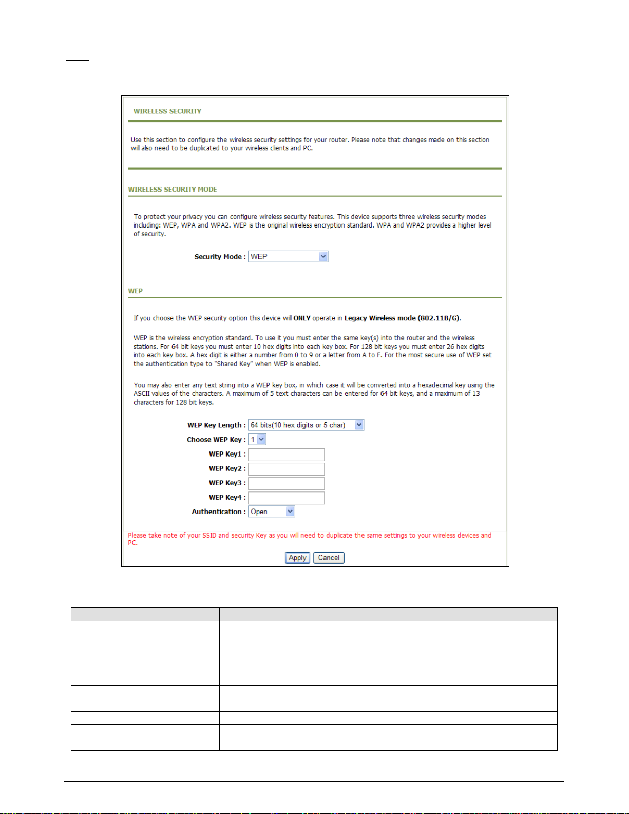
WEP
If the Security Mode is set to WEP, the page as shown in the following figure appears:
The following table describes the parameters in this page.
Field
Description
WEP Key Length
You can select 64 bits or 128 bits from the drop-down list.
If you select 64 bits, you need to enter 10 hexadecimal
numbers or 5 characters.
If you select 128 bits, you need to enter 26 hexadecimal
numbers or 13 characters.
Choose WEP Key
Select the WEP key from the drop-down list. Its value range is 1—
4.
WEP Keys 1—4
Set the 64 bits or 128 bits key, in the format of Hex or ASCII.
Authentication
Select the authentication mode from the drop-down list. You can
select Open or Share Key.
Click Apply to save the settings.
Page 28
CONCEPTRONIC C150APRA2 ENGLISH
28
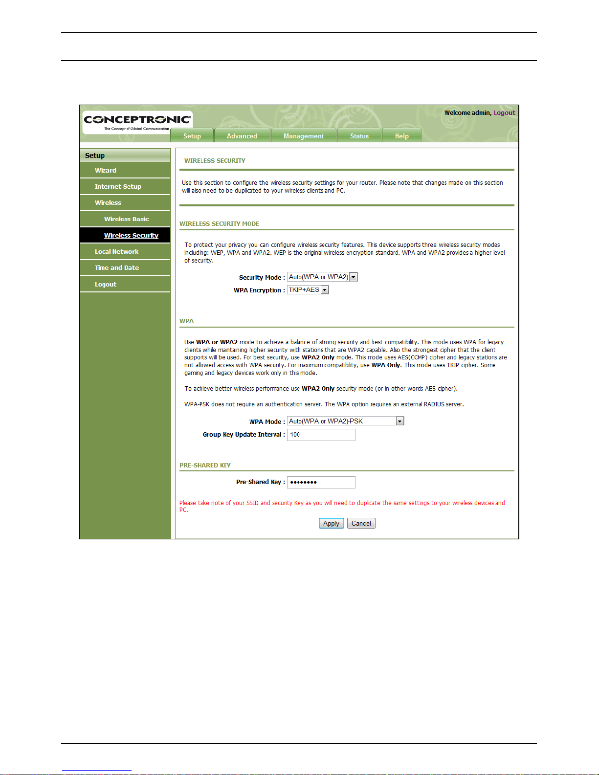
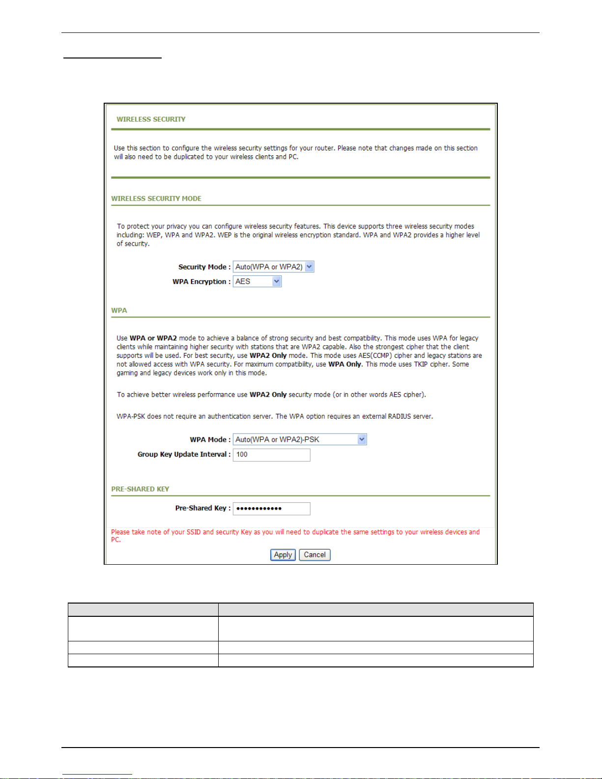
Auto (WPA or WPA2)
If the Security Mode is set to Auto (WPA or WPA2), the page as shown in the following figure
appears:
The following table describes the parameters in this page.
Field
Description
WPA Mode
You can select Auto (WPA or WPA2)-PSK or Auto (WPA or
WPA2)-WPA for Enterprise from the drop-down list.
Group Key Update Interval
Set the interval for updating the key.
Pre-Shared Key
Set the preshared key to identify the workstation.
Page 29
CONCEPTRONIC C150APRA2 ENGLISH
29
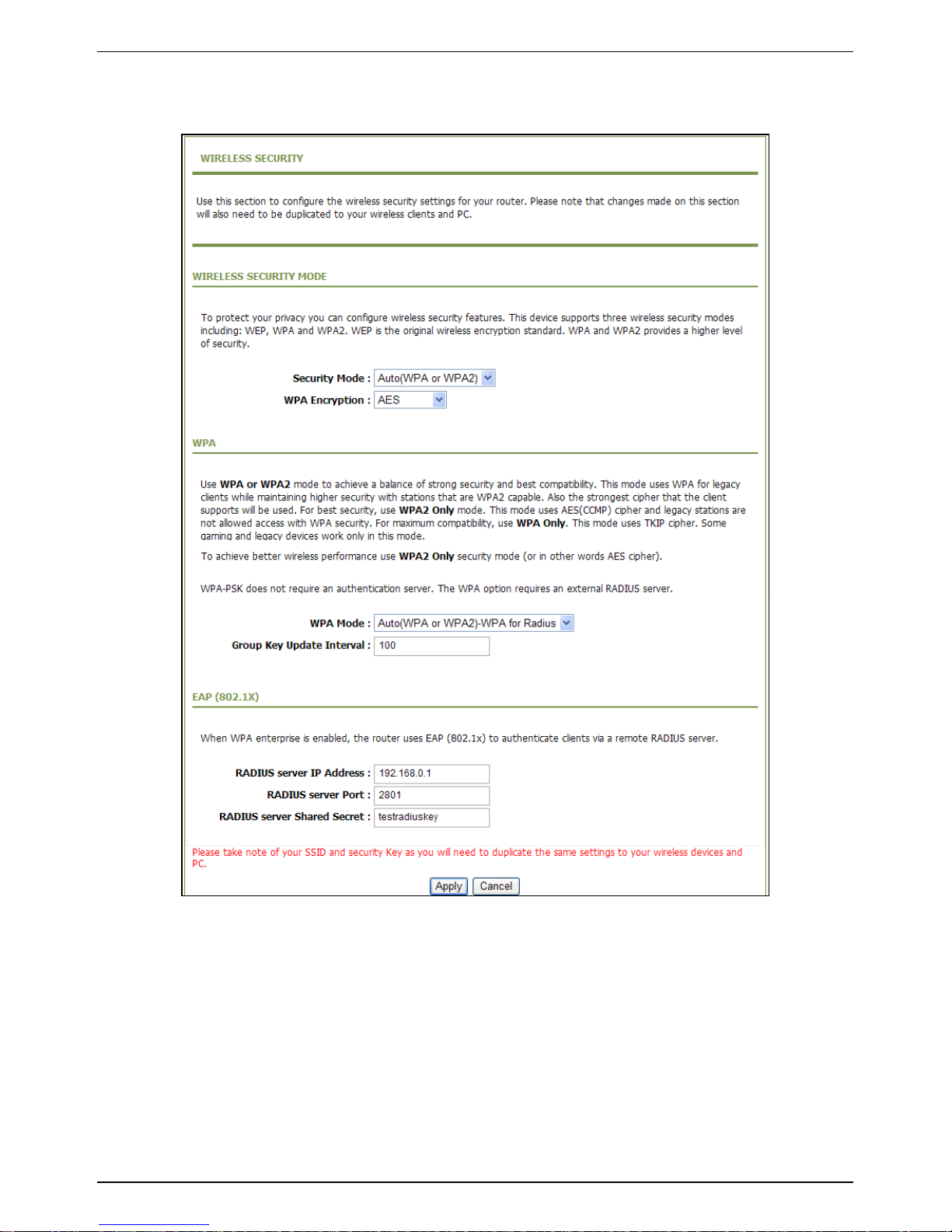
If the WPA Mode is set to Auto (WPA or WPA2)-Enterprise, the page as shown in the following
figure appears:
You need to enter the IP address, port, shared key of the RADIUS server.
Click Apply to save the settings.
Page 30
CONCEPTRONIC C150APRA2 ENGLISH
30
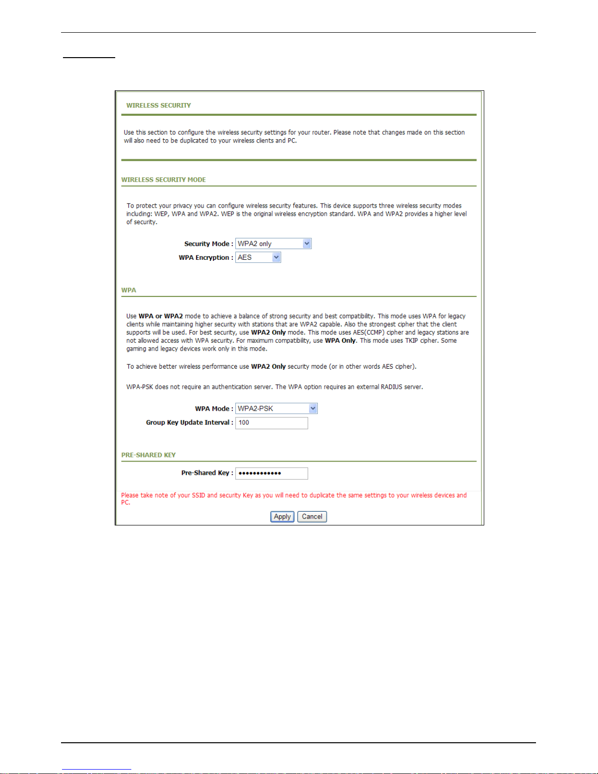
WPA2 Only
If the Security Mode is set to WPA2 only, the page as shown in the following figure appears:
Parameters in this page are similar to those in the page for Auto (WPA or WPA2).
Click Apply to save the settings.
Page 31

CONCEPTRONIC C150APRA2 ENGLISH
31
WPA Only
If the Security Mode is set to WPA only, the page as shown in the following figure appears:
Parameters in this page are similar to those in the page for Auto (WPA or WPA2).
Click Apply to save the settings.
Page 32

CONCEPTRONIC C150APRA2 ENGLISH
32
5.3.4 Setup - Local Network
You can configure the LAN IP address according to the actual application. The preset IP address is
192.168.0.1. You can use the default settings and DHCP service to manage the IP settings of the
private network. The IP address of the device is the base address used for DHCP. To use the device
for DHCP in your LAN, the IP address pool used for DHCP must be compatible with the IP address of
the device. The IP address available in the DHCP IP address pool changes automatically if the IP
address of the device changes.
You can also enable the secondary LAN IP address. The primary and the secondary LAN IP addresses
must be in different network segments.
Choose Setup > Local Network. The LOCAL NETWORK page as shown in the following figure
appears:
Page 33

CONCEPTRONIC C150APRA2 ENGLISH
33
By default, Enable DHCP Server is selected for the LAN interface of the device. DHCP service
provides IP settings to workstations configured to automatically obtain IP settings that are
connected to the device through the Ethernet port. When the device is used for DHCP, it becomes
the default gateway for DHCP client connected to it. If you change the IP address of the device, you
must also change the range of IP addresses in the pool used for DHCP on the LAN. The IP address
pool can contain up to 253 IP addresses.
Click Apply to save the settings.
In the LOCAL NETWORK page, you can assign LAN IP addresses for specific computers according to
their MAC addresses.
Click Add to add static DHCP reservation. The page as shown in the following figure appears:
The following table describes the parameters in this page.
Field
Description
Enable
Select the check box to reserve the IP address for the designated
PC with the configured MAC address.
Computer Name
Enter the computer name. It helps you to recognize the PC with
the MAC address. For example, Father‘s Laptop.
IP Address
Enter the IP address of the computer.
MAC Address
Enter the MAC address of the computer.
Click Apply to save the settings.
After the DHCP reservation information is saved, the DHCP reservations list displays the information.
If the DHCP reservations list is not empty, you can select one or more items and click Edit or
Delete.
The NUMBER OF DYNAMIC DHCP CLIENTS page displays the DHCP clients (PCs or Laptops) currently
connected to the device and the detailed information of the connected computers.
Page 34

CONCEPTRONIC C150APRA2 ENGLISH
34
5.3.5 Setup - Time and Date
Choose Setup > Time and Date. The TIME AND DATE page as shown in the following figure appears:
In the TIME AND DATE page, you can configure, update, and maintain the time of the internal
system clock. You can set the time zone that you are in and the network time protocol (NTP) server.
You can also set daylight saving time to automatically adjust the time when needed.
Select Automatically synchronize with Internet time servers.
Select the appropriate time server and the time zone from the corresponding drop-down lists.
Select Enable Daylight Saving if necessary. Enter the correct the start and end time of the daylight
saving.
Click Apply to save the settings.
Page 35

CONCEPTRONIC C150APRA2 ENGLISH
35
5.3.6 Setup - Logout
Choose Setup > Logout. The page as shown in the following figure appears:
Click Logout to log out of the configuration page.
Page 36

CONCEPTRONIC C150APRA2 ENGLISH
36
5.4 Advanced
This section contains advanced features used for network management, security and administrative
tools to manage the device. You can view the status and other information of the device, to
examine the performance and troubleshoot.
5.4.1 Advanced – Port Forwarding
This function is used to open ports in your device and re-direct data through these ports to a single
PC in your network (WAN-to-LAN traffic). It allows remote users to access services in your LAN, such
as FTP for file transfers or SMTP, and POP3 for e-mail. The device receives remote requests for
these services at your public IP address. It uses the specified TCP or UDP protocol and port, and
redirects these requests to the server on your LAN with the specified LAN IP address. Note that the
specified private IP address must be within the available IP address range of the subnet where the
device is in.
Choose Advanced > Port Forwarding. The page as shown in the following figure appears:
Click Add to add a virtual server. See the following figure:
Page 37

CONCEPTRONIC C150APRA2 ENGLISH
37
Select a service for a preset application or enter the name in the Custom Server field.
Enter an IP address in the Server IP Address field, to appoint the corresponding PC to receive
forwarded packets.
The port table displays the ports that you want to open on the device. The Protocol indicates the
type of protocol used by each port.
Page 38

CONCEPTRONIC C150APRA2 ENGLISH
38
Click Apply to save the settings. The page as shown in the following figure appears. A virtual server
is added.
Page 39

CONCEPTRONIC C150APRA2 ENGLISH
39
5.4.2 Advanced – Advanced Wireless
This function is used to modify the standard 802.11g wireless settings. It is recommended not
changing the default settings, because incorrect settings may affect the performance of the
wireless performance. The default settings provide the best wireless performance in most
environments.
Choose Advanced > Advanced Wireless. The ADVANCED WIRELESS page as shown in the following
figure appears:
Page 40

CONCEPTRONIC C150APRA2 ENGLISH
40
5.4.2.1 Advanced – Advanced Wireless – Advanced Settings
In the ADVANCED WIRELESS page, click Advanced Settings. The page as shown in the following
figure appears:
Page 41

CONCEPTRONIC C150APRA2 ENGLISH
41
The following table describes the parameters in this page.
ADVANCED WIRELESS SETTINGS
Field
Description
Transmission Rate
Select the transmission rate of the wireless network from the
drop-down list.
Multicast Rate
Select the multicast transmission rate of the wireless network
from the drop-down list. You can select Lower or Higher.
Transmit Power
Select the power for data transmission from the drop-down list.
You can select 100%, 80%, 60%, 40%, or 20%.
Beacon Period
By default, the wireless beacon frame sends the data once every
100ms. Its value range is 20—1024.
RTS Threshold
The threshold of transmission request. Its value range is 0—2347
and the default value is 2346.
Fragmentation Threshold
Its value range is 256—2346 and the default value is 2345.
DTIM Interval
Data beacon proportion (transmission quantity indication). Its
value range is 1—255 and the default value is 100.
Preamble Type
Select the preamble code from the drop-down list. You can select
long or short.
SSID
Field
Description
Enable Wireless
Select or deselect the check box to enable or disable the wireless
function.
Wireless Network Name
(SSID)
Set the wireless network name, that is, SSID. SSID is used to
distinguish different wireless networks.
Visibility Status
Select whether to hide the AP. You can select Visible or Invisible.
If you select Invisible, the AP is hidden and the terminal cannot
obtain the SSID through passive scanning.
User Isolation
Select whether users of the AP can communicate with each other.
You can select Off or On from the drop-down list. On indicates
that computers connected to the device cannot communicate
with each other.
Disable WMM Advertise
Select whether to disable WMM. You can select Off or On.
Max Clients
Set the maximum number of clients that can be connected to the
AP at the same time. Its value range is 0—32.
GUEST/VIRTUAL ACCESS POINTS-1—3
Field
Description
Enable Wireless Guest
Network
Select or deselect the check box to enable or disable the wireless
interface.
Guest SSID
Similar to the primary SSID, it identifies a wireless AP.
These settings are applicable only for more technically advanced users who have sufficient
knowledge about wireless LAN. Do not change these settings unless you know the effect of changes
on the device.
Click Apply to save the settings.
Page 42

CONCEPTRONIC C150APRA2 ENGLISH
42
5.4.2.2 Advanced – Advanced Wireless – MAC Filtering
In the ADVANCED WIRELESS page, click MAC Filtering. The page as shown in the following figure
appears:
Click Add and the page as shown in the following figure appears:
Page 43

CONCEPTRONIC C150APRA2 ENGLISH
43
The following table describes the parameters in this page.
Field
Description
User Name
Enter the name that identifies your configuration. For example,
kids.
Current PC’s MAC Address
Enter the MAC address of the computer that connects to the
device.
Other MAC Address
Enter the MAC address of another device that is included in MAC
filtering.
Schedule
Select the time of MAC filter from the drop-down list. You can
select always or never.
Manual Schedule
If you select this check box, you need to manually set the time of
MAC filtering.
Click Apply to save the settings.
Page 44

CONCEPTRONIC C150APRA2 ENGLISH
44
5.4.2.3 Advanced – Advanced Wireless – Security Settings
In the ADVANCED WIRELESS page, click Security Settings. The page as shown in the following figure
appears:
Select the desired SSID from the drop-down list.
Select the encryption type from the Security Mode drop-down list. You can select None, WEP,
AUTO (WPA or WPA2), WPA Only, or WPA2 Only. For parameters of different encryption types, see
section Error! Reference source not found. "Error! Reference source not found.‖.
Click Apply to save the settings.
Page 45

CONCEPTRONIC C150APRA2 ENGLISH
45
5.4.2.4 Advanced – Advanced Wireless – WPS Settings
In the ADVANCED WIRELESS page, click WPS Settings. The WIRELESS WPS page as shown in the
following figure appears:
Enabled: The WPS service is enabled by default.
Note: Ensure that the network card supports the WPS function.
You can use one of the following there methods to use WPS authentication:
Press the WPS button on the side panel for 3 seconds.
In the WIRELESS WPS page, click PBC. It has the same function of the WPS button on the
side panel. This is an optional method on wireless clients.
Note: You need a Registrar when using the PBC method in a special case in which the PIN is all
zeros.
In the WIRELESS WPS page, enter the PIN code provided by the station and click PIN. PIN
entry is a mandatory method of setup for all WPS certified devices.
Note: If you are using the PIN method, you need a Registrar, either an access point or a wireless
router, to initiate the registration between a new device and an active access point or a
wireless router.
Page 46

CONCEPTRONIC C150APRA2 ENGLISH
46
5.4.3 Advanced – DMZ
Choose Advanced > DMZ. The page as shown in the following figure appears:
In this page, you can enable a DMZ host. In this way, access from Internet to the WAN IP address of
the device is forwarded to the DMZ host and network server of the internal LAN is protected.
Click Apply to save the settings.
Page 47

CONCEPTRONIC C150APRA2 ENGLISH
47
5.4.4 Advanced – Parental Control
Choose Advanced > Parental Control. The PARENTAL CONTROL page as shown in the following
figure appears:
This page provides two useful tools for restricting Internet access. Block Website allows you to
quickly create a list of websites that you wish to prevent users from accessing. Block MAC Address
allows you to control Internet access by clients or PCs connected to the device.
Page 48

CONCEPTRONIC C150APRA2 ENGLISH
48
5.4.4.1 Advanced – Parental Control - Block Website
In the PARENTAL CONTROL page, click Block Website. The page as shown in the following figure
appears:
Click Add. The page as shown in the following page appears:
Page 49

CONCEPTRONIC C150APRA2 ENGLISH
49
Enter the website in the URL field. Select the time to block websites from the Schedule drop-down
list, or select Manual Schedule and set the corresponding time and days.
Click Submit to add the website to the BLOCK WEBSITE table.
Page 50

CONCEPTRONIC C150APRA2 ENGLISH
50
5.4.4.2 Advanced – Parental Control – Block MAC Address
In the PARENTAL CONTROL page, click Block MAC Address. The page as shown in the following
figure appears:
Note: The Block MAC Address feature from the PARENTAL CONTROL page refers to the MAC
Filtering from the ADVANCED SETTINGS page.
The following table describes the parameters in this page.
Field
Description
User Name
Enter the name that identifies your configuration. For example,
kids.
Current PC’s MAC Address
Enter the MAC address of the computer that connects to the
device.
Other MAC Address
Enter the MAC address of another device that is included in MAC
filtering.
Schedule
Select the time of MAC filter from the drop-down list. You can
select always or never.
Manual Schedule
If you select this check box, you need to manually set the time of
MAC filtering.
Click Apply to save the settings.
Page 51

CONCEPTRONIC C150APRA2 ENGLISH
51
5.4.5 Advanced – Filtering Options
Choose Advanced > Filtering Options. The FILTERING OPTIONS page as shown in the following
figure appears:
Page 52

CONCEPTRONIC C150APRA2 ENGLISH
52
5.4.5.1 Advanced – Filtering Options – Inbound IP Filtering
In the FILTERING OPTIONS page, click Inbound IP Filtering. The INCOMING IP FILTERING page as
shown in the following figure appears:
Click Add to add an inbound IP filter. The page as shown in the following figure appears:
Page 53

CONCEPTRONIC C150APRA2 ENGLISH
53
Enter the Filter Name and specify at least one of the following criteria: protocol,
source/destination IP address, subnet mask, and source/destination port.
Click Apply to save the settings.
Note: The settings apply only when the firewall is enabled.
The ACTIVE INBOUND FILTER in the INCOMING IP FILTERING page displays detailed information of
each created inbound IP filter. Click Delete to delete an IP filter. Note that the Delete button
appears only when at least one IP filter exists.
Page 54

CONCEPTRONIC C150APRA2 ENGLISH
54
5.4.5.2 Advanced – Filtering Options – Outbound IP Filtering
By default, all outgoing IP traffic from the LAN is allowed. The outbound filter allows you to create
a filter rule to block outgoing IP traffic by specifying a filter name and at least one criterion.
In the FILTERING OPTIONS page, click Outbound IP Filtering. The OUTGOING IP FILTERING page as
shown in the following figure appears:
Click Add to add an outbound IP filter. The page as shown in the following figure appears:
Page 55

CONCEPTRONIC C150APRA2 ENGLISH
55
Enter the Filter Name and specify at least one of the following criteria: protocol,
source/destination IP address, subnet mask, and source/destination port.
Click Apply to save the settings.
The ACTIVE OUTBOUND FILTER in the OUTGOING IP FILTERING page displays detailed information
OF each created outbound IP filter. Click Delete to delete an IP filter. Note that the Delete button
appears only when at least one IP filter exists.
Page 56

CONCEPTRONIC C150APRA2 ENGLISH
56
5.4.5.3 Advanced – Filtering Options – Bridge Filtering
In the FILTERING OPTIONS page, click Bridge Filtering. The page as shown in the following figure
appears:
This page is used to configure bridge parameters. In this page, you can modify the settings or view
the information of the bridge and its attached ports.
Click Add to add a bridge filter. The page as shown in the following figure appears:
Page 57

CONCEPTRONIC C150APRA2 ENGLISH
57
The following table describes the parameters in this page.
Field
Description
Protocol Type
Select the protocol type to be mapped from the drop-down list.
You can select PPPoE, IPv4, IPv6, AppleTalk, IPX, NetBEUI, or
IGMP.
Destination MAC Address
Enter the destination MAC address to be mapped.
Source MAC Address
Enter the source MAC address to be mapped.
Frame Direction
Select the frame direction to be mapped from the drop-down list.
The device supports frame direction from LAN to WAN and that
from WAN to LAN.
Time schedule
Select the time that you want to apply the rule from the dropdown list. You can select always or never.
Wan interface
Select the WAN interface to be mapped from the drop-down list.
Click Apply to save the settings.
Page 58

CONCEPTRONIC C150APRA2 ENGLISH
58
5.4.6 Advanced – QOS Config
Choose Advanced > QoS Config. The page as shown in the following figure appears:
Page 59

CONCEPTRONIC C150APRA2 ENGLISH
59
5.4.6.1 Advanced – QOS Config – QOS Interface Config
In the QoS CONFIG page, click QoS Interface Config. The page as shown in the following figure
appears:
Click Edit and the page as shown in the following figure appears:
Page 60

CONCEPTRONIC C150APRA2 ENGLISH
60
In this page, you can configure the uplink bandwidth and downlink bandwidth of each interface. The
uplink rate and the downlink rate are limited according to the configured bandwidth.
Click Apply to save the settings.
Page 61

CONCEPTRONIC C150APRA2 ENGLISH
61
5.4.6.2 Advanced – QOS Config – QOS Queue Config
In the QoS CONFIG page, click Qos Queue Config. The page as shown in the following figure
appears:
In this page, you can configure the priority of the queue. The device supports the following three
priority levels: high, medium, low. The device handles packets of the high queue priority first, then
packets of medium, and finally packets of low priority.
Click Add. The page as shown in the following figure appears:
Page 62

CONCEPTRONIC C150APRA2 ENGLISH
62
Click Apply to save the settings.
Page 63

CONCEPTRONIC C150APRA2 ENGLISH
63
5.4.6.3 Advanced – QOS Config – QOS Classify Config
In the QoS CONFIG page, click QoS Classify Configuration. The page as shown in the following
figure appears:
This page displays the classes. Click Add and the page as shown in the following figure appears:
Page 64

CONCEPTRONIC C150APRA2 ENGLISH
64
Page 65

CONCEPTRONIC C150APRA2 ENGLISH
65
The following table describes the parameters in this page.
Field
Description
Traffic Class Name
Enter the name of the traffic class.
Enable Classification
Select or deselect the check box to enable or disable QoS
classification.
SPECIFY TRAFFIC CLASSIFICATION RULES
Field
Description
Classification Type
Select L1&L2 or L3&L4 from the drop-down list.
L1&L2 maps to the features of layer 1 and layer 2, such as
the MAC address.
L3&L4 maps to the features of layer 3 and layer 4, such as
the IP address and the port.
Physical Lan Port
Select the physical port of the packet from the drop-down list.
For example, ethernet1, ethernet2, ethernet3, and ethernet4.
Source MAC Address
Enter the source MAC address of the packet.
Source MAC Mask
Use mask 000000ffffff to mask the MAC address. 00 indicates not
mapped and ff indicates mapped.
Destination MAC Address
Enter the destination MAC address of the packet.
Destination MAC Mask
Use mask 000000ffffff to mask the MAC address. 00 indicates not
mapped and ff indicates mapped
Ethernet Type
Select the layer 2 protocol type from the drop-down list. For
example, IP protocol and IPX protocol.
802.1p Priority
Select the 802.1p priority of the packet from the drop-down list.
You can select no assign or a value in the range of 0—7. Note that
this function is not supported at the moment.
SPECIFIC TRAFFIC CLASSIFICATION RESULT
Field
Description
Assign Classification
Queue
Specify the queue to which the packet belongs. You can set the
queue in the classification configuration.
Mark DSCP
Attach the DSCP mark to the mapped packet.
Mark 802.1p Priority
Attach the 802.1p mark to the mapped packet.
Click Apply to save the settings.
Page 66

CONCEPTRONIC C150APRA2 ENGLISH
66
5.4.7 Advanced – Firewall Settings
A denial-of-service (DoS) attack is one of the most common network attacks and is characterized by
an explicit attempt by attackers to prevent legitimate users of a service from using that service. It
usually leads to overload of system server or core dump of the system.
Choose Advanced > Firewall Settings. The page as shown in the following figure appears:
Click Apply to save the settings.
Page 67

CONCEPTRONIC C150APRA2 ENGLISH
67
5.4.8 Advanced – DNS
Domain name system (DNS) is an Internet service that translates domain names into IP addresses.
Because domain names are alphabetic, they are easier to remember. The Internet, however, is
actually based on IP addresses. Each time you use a domain name, a DNS service must translate the
name into the corresponding IP address. For example, the domain name www.example.com might
be translated to 198.105.232.4.
The DNS system is, in fact, its own network. If one DNS server does not know how to translate a
particular domain name, it asks another one, and so on, until the correct IP address is returned.
Choose Advanced > DNS. The page as shown in the following figure appears:
Page 68

CONCEPTRONIC C150APRA2 ENGLISH
68
The following table describes the parameters in this page.
Field
Description
Obtain DNS server address
automatically
If you select this radio button, the device automatically obtains IP
address of the DNS server from the ISP. You need not manually
enter the IP address of the server.
Use the following DNS
server addresses
If you select this radio button, you need to manually enter the IP
address of the server provided by the ISP.
WAN Connection
Select the WAN interface of the DNS server to be connected from
the drop-down list.
Preferred DNS server
Enter the IP address of the primary DNS server.
Alternate DNS server
Enter the IP address of the secondary DNS server. If the primary
DNS server fails to work, the device tries to connect the
secondary DNS server.
Click Apply to save the settings.
Page 69

CONCEPTRONIC C150APRA2 ENGLISH
69
5.4.9 Advanced – Dynamic DNS
The device supports dynamic domain name service (DDNS). The dynamic DNS service allows a
dynamic public IP address to be associated with a static host name in any of the many domains, and
allows access to a specified host from various locations on the Internet. Click a hyperlinked URL in
the form of hostname.dyndns.org and allow remote access to a host. Many ISPs assign public IP
addresses using DHCP, so locating a specific host on the LAN using the standard DNS is difficult. For
example, if you are running a public web server or VPN server on your LAN, DDNS ensures that the
host can be located from the Internet even if the public IP address changes. DDNS requires that an
account be set up with one of the supported DDNS service providers (DyndDNS.org).
Choose Advanced > Dynamic DNS. The page as shown in the following page appears:
Click Add to add dynamic DNS. The page as shown in the following figure appears:
Page 70

CONCEPTRONIC C150APRA2 ENGLISH
70
The following table describes the parameters in this page.
Field
Description
DDNS provider
Select the DDNS provider from the drop-down list. You can select
DynDns.org, TZO, or GnuDIP.
Hostname
Enter the host name that you register with your DDNS provider.
Interface
Select the interface that is used for DDNS service from the dropdown list. The IP address of the interface corresponds to the host
name.
Username
Enter the user name of your DDNS account.
Password
Enter the password of your DDNS account.
Click Apply to save the settings.
Page 71

CONCEPTRONIC C150APRA2 ENGLISH
71
5.4.10 Advanced – Network Tools
Choose Advanced > Network Tools. The NETWORK TOOLS page as shown in the following figure
appears:
Page 72

CONCEPTRONIC C150APRA2 ENGLISH
72
5.4.10.1 Advanced – Network Tools – Port Mapping
In the NETWORK TOOLS page, click Port Mapping. The page as shown in the following figure
appears:
In this page, you can bind the WAN interface and the LAN interface to the same group.
Click Add to add port mapping. The page as shown in the following figure appears:
Page 73

CONCEPTRONIC C150APRA2 ENGLISH
73
To create a mapping group, do as follows:
Step 1 Enter the group name.
Step 2 Select interfaces from the Available Interfaces list and click the <- arrow button to add
them to the grouped interface list, in order to create the required mapping of the ports.
The group name must be unique.
Step 3 Click Apply to save the settings.
Page 74

CONCEPTRONIC C150APRA2 ENGLISH
74
5.4.10.2 Advanced – Network Tools – IGMP Proxy
In the NETWORK TOOLS page, click IGMP Proxy. The page as shown in the following figure appears:
IGMP proxy enables the device to issue IGMP host messages on behalf of hosts that the system
discovered through standard IGMP interfaces. The device serves as a proxy for its hosts after you
enable the function.
Select Enable IGMP Proxy and select the desired WAN and corresponding LAN interface.
Click Apply to save the settings.
Page 75

CONCEPTRONIC C150APRA2 ENGLISH
75
5.4.10.3 Advanced – Network Tools – IGMP Snooping
When IGMP snooping is enabled, only hosts that belong to the group receive the multicast packets.
If a host is deleted from the group, the host cannot receive the multicast packets any more.
In the NETWORK TOOLS page, click IGMP Snooping. The page as shown in the following figure
appears:
Click Apply to save the settings.
Page 76

CONCEPTRONIC C150APRA2 ENGLISH
76
5.4.10.4 Advanced – Network Tools – UPnP
In the NETWORK TOOLS page, click Upnp. The page as shown in the following figure appears:
In this page, you can enable universal plug and play (UPnP) and then the system serves as a
daemon.
UPnP is widely applied in audio and video software. It automatically searches devices in the
network. If you are concerned about UPnP security, you can disable it.
Select the WAN and LAN interfaces at which you want to enable UPnP and click Apply to save the
settings.
Page 77

CONCEPTRONIC C150APRA2 ENGLISH
77
5.4.10.5 Advanced – Network Tools – ADSL
In the NETWORK TOOLS page, click ADSL. The page as shown in the following figure appears:
In this page, you can select the ADSL modulation. Normally, you are recommended to keep the
factory defaults. The device supports the following modulation types: G.Dmt, G.lite, T1.413, ADSL2,
AnnexL, ADSL2+, and AnnexM. The device negotiates the modulation mode with the DSLAM.
Click Apply to save the settings.
Page 78

CONCEPTRONIC C150APRA2 ENGLISH
78
5.4.10.6 Advanced – Network Tools – SNMP
In the NETWORK TOOLS page, click SNMP. The page as shown in the following figure appears:
In this page, you can set the SNMP parameters. The following table describes the parameters in this
page.
Field
Description
Enable SNMP Agent
Select or deselect the check box to enable or disable SNMP agent.
Read Community
Universal character to obtain the device information. It is similar
to the password. The SNMP application entity can use it to
directly obtain the device information.
Set Community
Universal character to modify the device configuration. It is
similar to the password. The SNMP application entity can use it to
directly modify the device configuration.
Trap Manager IP
Enter the address of the server that receives the trap message.
Trap Community
The field that is included in the trap message sent by the device.
Trap Version
Select the trap version from the drop-down list. You can select v1
or v2c.
Click Apply to save the settings.
Page 79

CONCEPTRONIC C150APRA2 ENGLISH
79
5.4.11 Advanced – Routing
Choose Advanced > Routing. The page as shown in the following page appears:
This page contains the following function items: static route, default gateway, and RIP settings.
Page 80

CONCEPTRONIC C150APRA2 ENGLISH
80
5.4.11.1 Advanced – Routing – Static Routing
Choose Advanced > Routing and click Static Route. The page as shown in the following figure
appears:
This page displays the information of existing static routes.
Click Add and the page as shown in the following figure appears:
Page 81

CONCEPTRONIC C150APRA2 ENGLISH
81
The following table describes the parameters in this page.
Field
Description
Destination Network
Address
The destination IP address of the device.
Subnet Mask
The subnet mask of the destination IP address.
Use Gateway IP Address
The gateway IP address of the device.
Use Interface
Select the interface of the static routing used by the device from
the drop-down list.
Note: You can enter the gateway IP address of the device in the Use Gateway IP Address field or
set the User Interface, but cannot apply the two settings at the same time.
Click Apply to save the settings.
Page 82

CONCEPTRONIC C150APRA2 ENGLISH
82
5.4.11.2 Advanced – Routing – Default Gateway
Choose Advanced > Routing and click Default Gateway. The page as shown in the following figure
appears:
In this page, you can select Enable Automatic Assigned Default Gateway, or enter the information
in the Use Gateway IP Address and Use Interface fields.
Click Apply to save the settings.
Page 83

CONCEPTRONIC C150APRA2 ENGLISH
83
5.4.11.3 Advanced – Routing – RIP
Choose Advanced > Routing and click RIP. The page as shown in the following figure appears:
In this page, you can view the interfaces on your device that use RIP and the version of the protocol
used. If you enable RIP, the device communicates with other devices using the routing information
protocol (RIP).
Click Apply to save the settings.
Page 84

CONCEPTRONIC C150APRA2 ENGLISH
84
5.4.12 Advanced – Schedules
Choose Advanced > Schedules. The page as shown in the following figure appears:
Click Add to add a schedule rule. The page as shown in the following figure appears:
Page 85

CONCEPTRONIC C150APRA2 ENGLISH
85
The following table describes the parameters in this page.
Field
Description
Name
Set the name of the schedule.
Day(s)
You can select one, more, or all of the seven days in a week.
All Day – 24 hrs
If you select the check box, the rule applies throughout the 24
hours of the day.
Start Time
Set the start time of the firewall.
End Time
Set the end time of the firewall.
Click Apply to save the settings.
5.4.13 Advanced – Logout
Choose Advanced > Logout. The page as shown in the following figure appears:
Click Logout to log out of the configuration page.
Page 86

CONCEPTRONIC C150APRA2 ENGLISH
86
5.5 Management
5.5.1 Management – System Management
Choose Management > System Management. The System page as shown in the following figure
appears:
In this page, you can restart the device, back up the current settings to a file, update the backup
file, and restore the factory default settings.
The following table describes the buttons in this page.
Button
Description
Reboot
Restart the device.
Backup Setting
Specify the path to back up the current configuration in a
configuration file on your computer. You can rename the
configuration file.
Update Setting
Click Browse… to select the configuration file of device and click
Update Setting to update the configuration of the device.
Restore Default Setting
Reset the device to default settings.
Caution: Do not turn off your device or press the Reset button when the procedure is in
progress.
Page 87

CONCEPTRONIC C150APRA2 ENGLISH
87
5.5.2 Management – Firmware Update
Choose Management > Firmware Update. The page as shown in the following figure appears:
In this page, you can upgrade the firmware of the device. To update the firmware, do as follows:
Step 1 Click Browse…to select the file.
Step 2 Click Update Firmware to update the configuration file.
The device loads the file and reboots automatically.
Caution: Do not turn off your device or press the Reset button when the procedure is in
progress
Page 88

CONCEPTRONIC C150APRA2 ENGLISH
88
5.5.3 Management – Access Controls
Choose Management > Access Controls. The ACCESS CONTROLS page as shown in the following
figure appears:
This page contains Account Password, Services, and IP Address.
Page 89

CONCEPTRONIC C150APRA2 ENGLISH
89
5.5.3.1 Management – Access Controls – User Management
In the ACCESS CONTROLS page, click Account Password. The page as shown in the following figure
appears:
In this page, you can change the password and set the time for automatic logout.
You are recommended to change the default password to ensure the security of your network.
Ensure that you remember the new password or write it down and keep it in a safe location for
future reference. If you forget the password, you need to reset the device to the factory default
settings. In that case, all configuration settings of the device are lost.
Page 90

CONCEPTRONIC C150APRA2 ENGLISH
90
The following table describes the parameters in this page.
ACCOUNT PASSWORD
Field
Description
Username
Select a user name from the drop-down list to access the device.
You can select admin.
Current Password
Enter the password of the user.
New Password
Enter the new password.
Confirm Password
Enter the new password again for confirmation.
WEB IDLE TIME OUT SETTINGS
Field
Description
Web Idle Time Out
Set the time after which the system automatically exits the
configuration page. Its value range is 5—30 minutes.
Click Apply to apply the settings.
Page 91

CONCEPTRONIC C150APRA2 ENGLISH
91
5.5.3.2 Management – Access Controls – Services
In the ACCESS CONTROLS page, click Services. The page as shown in the following figure appears:
In this page, you can enable or disable the services that are used by the remote host. For example,
if telnet service is enabled at port 23, the remote host can access the device by telnet through port
23.
Select the management services that you want to enable or disable at the LAN or WAN interface and
click Apply to apply the settings.
Caution: If you disable the HTTP service, you cannot access the configuration page of the
device any more.
Page 92

CONCEPTRONIC C150APRA2 ENGLISH
92
5.5.3.3 Management – Access Controls – IP Address
In the ACCESS CONTROLS page, click IP Address. The page as shown in the following figure
appears:
In this page, you can configure the IP address in the access control list (ACL). If ACL is enabled, only
devices of the specified IP addresses can access the device.
Select Enable Access Control Mode to enable ACL.
Note: If you enable ACL, ensure that the IP address of the host is in the ACL list.
Page 93

CONCEPTRONIC C150APRA2 ENGLISH
93
Click Add. The page as shown in the following figure appears:
Enter the IP address of the desired device in the IP Address field and click Apply to apply the
settings.
Page 94

CONCEPTRONIC C150APRA2 ENGLISH
94
5.5.4 Management – Diagnosis
Choose Management > Diagnosis. The page as shown in the following figure appears:
In this page, you can test the connection status of the device.
Click Return Diagnostics Test to run diagnostics. The page as shown in the following figure appears:
Note: The above diagnostics information is an example. In your situation, the results can be
different.
Page 95

CONCEPTRONIC C150APRA2 ENGLISH
95
5.5.5 Management – Log Configuration
Choose Management > Log Configuration. The SYSTEM LOG page as shown in the following figure
appears:
In this page, you can enable the log function. You can set Mode to Local, Remote, or Both. Local
indicates to save the log in the local computer. Remote indicates to send the log to the remote log
server. Both indicates to save the log in the local computer and the remote log server.
To log the events, do as follows:
Step 1 Select Enable Log.
Step 2 Select a mode from the drop-down list.
If you select Remote or Both, enter the IP address and port number of the server.
Step 3 Click Apply to apply the settings.
Step 4 Click View System Log to view the detail information of the system log.
Page 96

CONCEPTRONIC C150APRA2 ENGLISH
96
5.5.6 Management – Logout
Choose Management > Logout. The page as shown in the following figure appears:
Click Logout to log out of the configuration page.
Page 97

CONCEPTRONIC C150APRA2 ENGLISH
97
5.6 Status
In the Status page, you can view the system information and monitor the performance of the
device.
5.6.1 Status – Device Info
Choose Status > Device Info. The page as shown in the following figure appears:
The page displays the summary of the device status, including the system information, WAN
connection information, wireless information, and local network information.
Page 98

CONCEPTRONIC C150APRA2 ENGLISH
98
5.6.2 Status – Wireless Clients
Choose Status > Wireless Clients. The page as shown in the following page appears:
The page displays authenticated wireless stations and their statuses.
5.6.3 Status – DHCP Clients
Choose Status > DHCP Clients. The page as shown in the following page appears:
This page displays all client devices that obtain IP addresses from the device. You can view the host
name, IP address, MAC address, and expiration time of the IP address.
Page 99

CONCEPTRONIC C150APRA2 ENGLISH
99
5.6.4 Status – Logs
Choose Status > Logs. The page as shown in the following figure appears:
This page displays the system log. Click Refresh to refresh the system log shown in the box.
Page 100

CONCEPTRONIC C150APRA2 ENGLISH
100
5.6.5 Status – Statistics
Choose Status > Statistics. The page as shown in the following figure appears:
This page displays the statistics information of the network and data transmission. The information
helps technicians to identify whether the device is functioning properly. The information does not
affect the functions of the device.
 Loading...