

Comtrol Rocket linx ES8508, Rocket linx ES8508F, Rocket linx ES8505-XT, Rocket linx ES8508F-XT Quick Installation Manual
Page 1

QUICK INSTALLATION GUIDE
2000577 Rev B | Release Date - September, 2013
ROCKETLINX
ES8508
ES8508 | ES8508F | ES8508-XT | ES8508F-XT
Page 2

INTRODUCTION
The RocketLinx ES8508 series features advanced Layer 2 management
and security for deployment in mission critical networking applications.
The RocketLinx ES8508 series includes the following models:
• ES8508 with 8 Fast Ethernet ports
• ES8508F with 6 Fast Ethernet ports and 2 ber ports (100BASE-FX
Single-Mode and Multi-Mode models)
• ES8508-XT with 8 Fast Ethernet ports with an extended temperature
range
• ES8508F-XT with 6 Fast Ethernet ports and 2 ber ports
(100BASE-FX Single-Mode and Multi-Mode models) with an extended
temperature range
The different ES8508 models are simply referred to as the ES8508 unless
there is model specic information.
See the Comtrol website for complete product specications.
INSTALLATION OVERVIEW
You can use the following overview to install the ES8508. If you need
more detailed installation and conguration information, you can refer
to the
RocketLinx ES8508 Series User Guide
, which is available on the
RocketLinx CD or you can download the latest version.
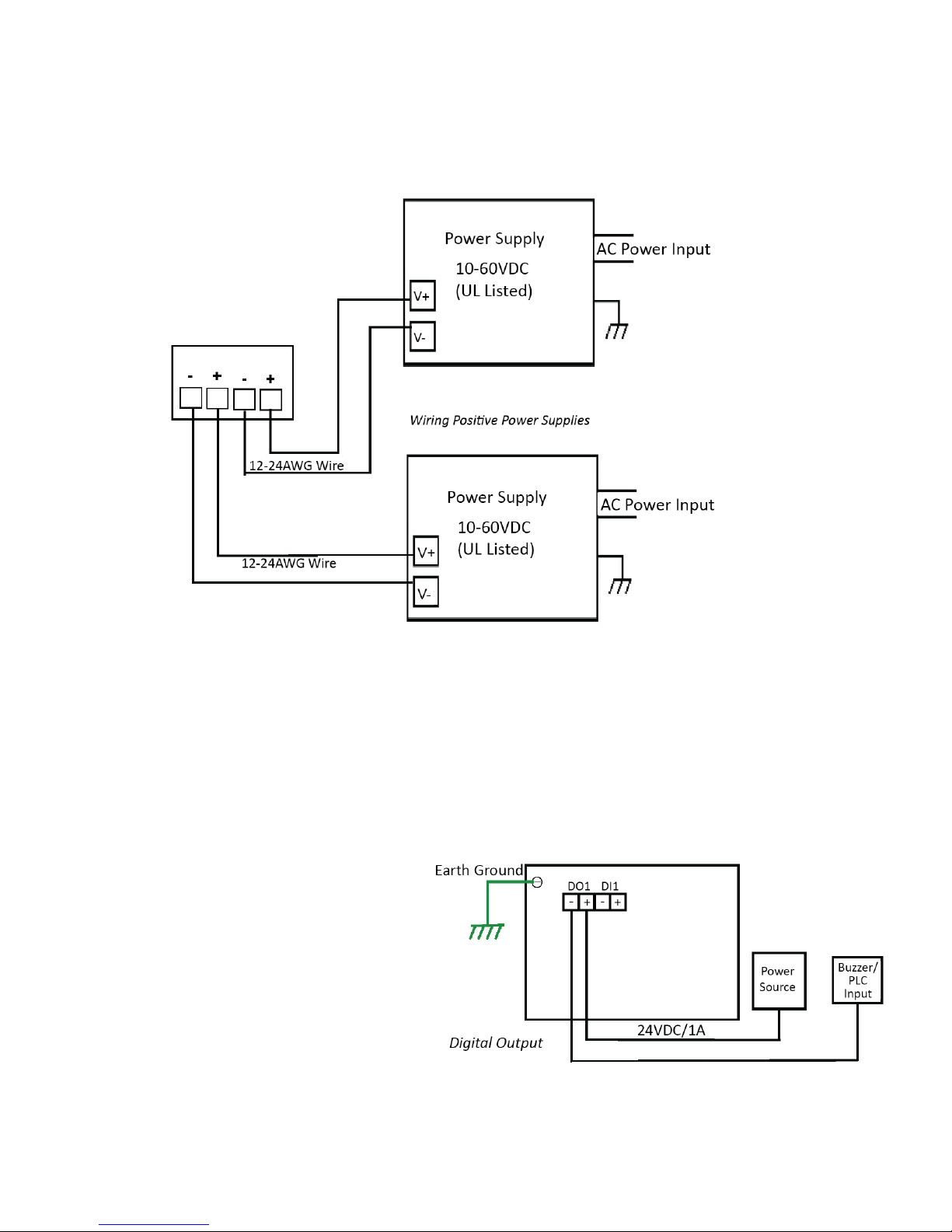
Wiring the Power Inputs
The ES8508 provides redundant power, reverse polarity protection, and
accepts a positive or negative power source but PW1 and PW2 must apply
to the same mode. The recommended working voltage is 24VDC with an
input range of 10-60VDC and a maximum power consumption of 15W.
1. Insert the positive and negative wires into PW+ and PW- contacts
(PW1 and PW2). You can connect a single power supply or two power
supplies depending on your requirements.
2. If both power inputs are connected, the ES8508 will be powered from
the highest connected voltage. The unit can be congured to signal an
alarm for loss of power in either PW1 or PW2.
3. Tighten the wire-clamp screws to prevent the wires from being
loosened.
1 2 3
Page 3
Wiring the Digital Input
The digital input (DI) contacts
are on the terminal block
connector on the bottom of the
ES8508. The contacts accept
one external DC type signal input
and can be congured to send
alert message through Ethernet
when the signal is changed.
The DI supports isolated input circuit with digital high level input of 11VDC
to 30VDC and digital low level input 0VDC to 10VDC. Do not apply a higher
voltage than the specication; it may cause internal circuit damage or a
cause an incorrect DI action.
Grounding the ES8508
Wire the earth ground to ensure the system is not damaged by noise or
any electrical shock, we recommend that you to make a direct connection
between the ES8508 and earth ground.
Using a screw driver, loosen the earth ground screw on the bottom of
the ES8508 and then tighten the screw after the earth ground wire is
connected.
Mounting the ES8508
The DIN rail clip is attached to the ES8508.
1. Insert the upper end of DIN rail clip into the back of DIN rail track from
2. Lightly push the bottom of DIN rail clip into the track.
3. Verify that the DIN rail clip is tightly attached on the track.
Connecting RJ45 Ports
Connect one end of an Ethernet cable into the Ethernet port of the ES8508
and the other end to the attached networking device. The RJ45 ports
support 10/100Mbps half/full-duplex. All RJ45 ports auto-detect the signal
Power should be disconnected from the power supply before connecting
it to the switch. Otherwise, your screwdriver blade can inadvertently short
your terminal connections to the grounded enclosure.
Wiring the Alarm Relay Output
The alarm relay output or digital output (DO) contacts are on the terminal
block connector on the bottom of the ES8508.
The relay contact supports up to 1A at 24VDC. Do not apply voltage and
current higher than the specications.
The alarm relay output is
controlled by the pre-dened
operating rules. To activate the
alarm relay output function, refer
to the
RocketLinx ES8508
Series User Guide
.
Page 4

Wiring the Digital Input
from connected devices to negotiate the link speed and duplex mode. Auto
The digital input (DI) contacts
are on the terminal block
connector on the bottom of the
ES8508. The contacts accept
one external DC type signal input
and can be congured to send
alert message through Ethernet
when the signal is changed.
The DI supports isolated input circuit with digital high level input of 11VDC
to 30VDC and digital low level input 0VDC to 10VDC. Do not apply a higher
voltage than the specication; it may cause internal circuit damage or
cause an incorrect DI action.
Grounding the ES8508
Wire the earth ground to ensure the system is not damaged by noise or
MDI/MDIX allows users to connect another switch, hub, or workstation
without changing straight through or crossover cable.
Link/Act LEDs are lit to indicate traffic and link status, see the LEDs
subsection for more information.
Always make sure that the cables between the switches and attached
any electrical shock, we recommend that you make a direct connection
between the ES8508 and earth ground.
Using a screw driver, loosen the earth ground screw on the bottom of
the ES8508 and then tighten the screw after the earth ground wire is
connected.
Mounting the ES8508
The DIN rail clip is attached to the ES8508.
1. Insert the upper end of DIN rail clip into the back of DIN rail track from
its upper side.
2. Lightly push the bottom of DIN rail clip into the track.
3. Verify that the DIN rail clip is tightly attached on the track.
Connecting RJ45 Ports
Connect one end of an Ethernet cable into the Ethernet port of the ES8508
and the other end to the attached networking device. The RJ45 ports
devices (for example, switch, hub, or workstation) are less than 100 meters
(328 feet). You should use 10/100BASE-TX: Category 5 Cable or higher.
Connecting Fiber Ports (ES8508F/ES8508F-XT Models Only)
Connect the ber port to another Fiber Ethernet device using the following
diagram. An improper connection will cause the ber port to not work
properly. The ber port is a standard or square connector (SC). Make sure
that the ber mode of the cable matches the ber mode of the ES8508
(Single-Mode or Multi-Mode).
support 10/100Mbps half/full-duplex. All RJ45 ports auto-detect the signal
See the
you need ber cabling specications.
Page 5

4
from connected devices to negotiate the link speed and duplex mode. Auto
MDI/MDIX allows users to connect another switch, hub, or workstation
without changing straight through or crossover cable.
Link/Act LEDs are lit to indicate traffic and link status, see the LEDs
subsection for more information.
Always make sure that the cables between the switches and attached
devices (for example, switch, hub, or workstation) are less than 100 meters
(328 feet). You should use 10/100BASE-TX: Category 5 Cable or higher.
Connecting Fiber Ports (ES8508F/ES8508F-XT Models Only)
Connect the ber port to another Fiber Ethernet device using the following
diagram. An improper connection will cause the ber port to not work
properly. The ber port is a standard or square connector (SC). Make sure
that the ber mode of the cable matches the ber mode of the ES8508
(Single-Mode or Multi-Mode).
See the
ES8508 Series User Guide
if
you need ber cabling specications.
Page 6

ROCKETLINX
ES8508
ES8508 | ES8508F | ES8508-XT | ES8508F-XT
PROGRAMMING THE IP ADDRESS
Congure the IP address using one of the following methods:
• PortVision DX (available on the RocketLinx CD shipped with the
product)
• Web browser
• Telnet
• Command line interface (CLI) using the RS-232 console cable
The easiest way to congure a static IP address for your network in
the ES8508 is to use a Windows host and PortVision DX (see below).
For information about using other conguration methods, refer to the
RocketLinx ES8508 Series User Guide.
Note:
Optionally, you can use NetVision if you are accustomed to
using NetVision. PortVision DX is replacing NetVision. NetVision is not
documented in the RocketLinx ES8508 Series User Guide.
The following procedure uses PortVision DX to program network settings.
1. Install PortVision DX on a host system with a Windows operating
system. If you need assistance installing PortVision DX, see the
RocketLinx ES8508 Series User Guide.
2. Start PortVision DX. PortVision DX can be started from Start --> All
Programs --> Comtrol --> PortVision DX.
3. Click the Scan button.
4. Select the Comtrol product families that you want to locate and click
the Scan button.
5. Right-click the ES8508 in the Device List pane (lower) that you want to
congure and click Properties.
6. Enter a user-friendly Device Name.
7. Optionally, enter the ES8508 serial number, which displays a friendly
device name in the
Device List
pane on the main page.
8. Select DHCP IP or Static IP for the
IP Mode
.
• If you select DHCP IP, go to Step 9.
• If you select Static IP, enter an IP address, Subnet Mask, and
Default Gateway value for your network.
5 6 7
Page 7

ROCKETLINX
ES8508
ES8508 | ES8508F | ES8508-XT | ES8508F-XT
In-band management means that you connect remotely using the ES8508
IP address through the network. You can remotely connect with the
ES8508 Java applet web interface or a Telnet console and the CLI.
The following procedure uses a web browser to congure ES8508 features.
Refer to the
methods.
1. If necessary, install the latest version of the Java Runtime
2. Open a web browser and enter the IP address of the ES8508.
3. Click Run when Java prompts you to run the applet.
4. Enter admin for both the user name and the password when
5. Use the web interface to congure your device as needed for your
You can use the help system or the
for information about conguring RocketLinx ES8508 features.
COMTROL CUSTOMER SERVICE
You can use one of the following methods to contact Comtrol.
9. Optionally, select the appropriate Network Topology, which is an
informational eld.
10. Click the Apply Changes button.
11. Click Close to return to the main screen.
12. You are now ready to congure the ES8508 features.
LED INDICATORS
You can also view the LEDs for the ES8508 through the web interface
using the
Device Front Panel
page.
LED Name LED On LED Blinking LED Off
SYS Green: System ready Green: Firmware
loading
Power off
PWR1/2 Green: System power
ready
Not applicable System not ready
R.S. (Ring
Status)
Green: Ring is normal
Amber: Abnormal ring
Green: Ring with the
wrong port
Amber: The device’s
ring port failed
Switch working in slave
mode
DO1 Relay is active and
contacts have been
shorted
Not applicable DO not activated
DI1 High digital signal is
detected
Not applicable DI not activated
LNK/ACT Port is linked Port active Port link down or port
not connected
FEATURE CONFIGURATION
The ES8508 provides both in-band and out-band conguration methods:
Out-band management means that you congure the ES8508 using the
RS-232 console cable and the Command Line Interface (CLI) to access the
ES8508 without attaching an admin PC to the network. You can also use
out-bound management, if you lost the network connection to the ES8508.
Page 8

ROCKETLINX
ES8508
ES8508 | ES8508F | ES8508-XT | ES8508F-XT
In-band management means that you connect remotely using the ES8508
IP address through the network. You can remotely connect with the
ES8508 Java applet web interface or a Telnet console and the CLI.
The following procedure uses a web browser to congure ES8508 features.
Refer to the
methods.
1. If necessary, install the latest version of the Java Runtime
Environment, which is required to run the web management interface.
2. Open a web browser and enter the IP address of the ES8508.
3. Click Run when Java prompts you to run the applet.
4. Enter admin for both the user name and the password when
prompted.
5. Use the web interface to congure your device as needed for your
network.
You can use the help system or the
for information about conguring RocketLinx ES8508 features.
RocketLinx ES8508 Series User Guide
RocketLinx ES8508 Series User Guide
for other conguration
COMTROL CUSTOMER SERVICE
You can use one of the following methods to contact Comtrol.
Contact Method Web Address or Phone Number
Support http://www.comtrol.com/support
Downloads ftp://ftp.comtrol.com/html/ES8508_main.htm
Website http://www.comtrol.com
Phone +1 763.957.6000
 Loading...