

Page 1

SDR-54A
Satellite Demodulator
Installation and Operation Manual
Part Number MN/SDR54A.IOM Revision 4
Page 2

Page 3

Comtech EF Data is an ISO 9001
Registered Company.
SDR-54A
Satellite Demodulator
Installation and Operation Manual
Part Number MN/SDR54A.IOM
Revision 4
July 10, 2003
i
Page 4

Customer Support
Contact the Comtech EF Data Customer Support Department for:
Product support or training
Information on upgrading or returning a product
Reporting comments or suggestions concerning manuals
A Customer Support representative may be reached at:
Comtech EF Data
Attention: Customer Support Department
2114 West 7th Street
Tempe, Arizona 85281 USA
480.333.2200 (Main Comtech EF Data Number)
480.333.4357 (Customer Support Desk)
480.333.2161 FAX
or, E-Mail can be sent to the Customer Support Department at:
service@comtechefdata.com
Contact us via the web at www.comtechefdata.com
1. To return a Comtech EF Data product (in-warranty and out-of-warranty) for
repair or replacement:
2. Request a Return Material Authorization (RMA) number from the Comtech EF
Data Customer Support Department.
3. Be prepared to supply the Customer Support representative with the model
number, serial number, and a description of the problem.
4. To ensure that the product is not damaged during shipping, pack the product in
its original shipping carton/packaging.
5. Ship the product back to Comtech EF Data. (Shipping charges should be
prepaid.)
For more information regarding the warranty policies, see, p. xiv.
.
ii
Page 5

Table of Contents
CHAPTER 1. INTRODUCTION................................................................................. 1–1
1.1 Demodulator Functions .............................................................................................................................1–1
1.2 Overview......................................................................................................................................................1–2
1.3 Options ........................................................................................................................................................1–4
1.4 New in this Revision ...................................................................................................................................1–4
CHAPTER 2. INSTALLATION................................................................................... 2–1
2.1 Unpacking ...................................................................................................................................................2–1
2.2 System Installation .....................................................................................................................................2–2
CHAPTER 3. EXTERNAL CONNECTORS ............................................................... 3–1
3.1 External Connections ................................................................................................................................. 3–1
3.1.1 RF Input (J1)........................................................................................................................................3–2
3.1.2 Fault Connector (J2) ............................................................................................................................3–3
3.1.3 M&C Port (J3) ..................................................................................................................................... 3–3
3.1.3.1 Rear Panel Connector Pinout ...................................................................................................... 3–3
3.1.3.2 Front Panel Connector Pinout.....................................................................................................3–4
3.1.4 Data Out Connector (J4) Interface Type Jumpers ..............................................................................3–4
3.1.4.1 Data Out Connector (J4) Jumper Location .................................................................................3–5
3.1.4.2 Data Out Connector (J4) .............................................................................................................3–5
3.1.4.3 Data Out Connector (J4) .............................................................................................................3–6
3.1.5 Power Entry .........................................................................................................................................3–6
3.1.5.1 AC Option...................................................................................................................................3–6
3.1.5.2 48 VDC Option...........................................................................................................................3–7
3.1.5.3 24 VDC Option...........................................................................................................................3–7
3.1.6 Ground (GND).....................................................................................................................................3–7
iii
Page 6

SDR-54A Satellite Demodulator Revision 4
Preface MN/SDR54A.IOM
CHAPTER 4. OPERATION........................................................................................ 4–1
4.1 Front Panel..................................................................................................................................................4–1
4.1.1 Indicators .............................................................................................................................................4–2
4.1.2 LNB Power .......................................................................................................................................... 4–2
4.2 Configuration Setup ...................................................................................................................................4–2
4.3 Cooling Fan.................................................................................................................................................4–3
CHAPTER 5. DEMUX OPTION ................................................................................. 5–1
5.1 DEMUX Overview ..................................................................................................................................... 5–1
5.2 DEMUX 2/4-Channel (Option) .................................................................................................................5–2
5.2.1 Description...........................................................................................................................................5–2
5.2.2 Installation ...........................................................................................................................................5–3
5.2.3 DEMUX 2/4-Channel Specification....................................................................................................5–5
5.2.4 Tributary Data Interface Connector RS-422 (J4) ................................................................................5–5
5.3 DEMUX 8-Channel (Option).....................................................................................................................5–7
5.3.1 Description...........................................................................................................................................5–7
5.3.2 Installation ...........................................................................................................................................5–8
5.3.3 DEMUX 8-Channel Specification.....................................................................................................5–10
5.3.4 Tributary Data Interface Connector RS-422 (J5 and J6) ...................................................................5–11
CHAPTER 6. REED-SOLOMON ............................................................................... 6–1
6.1 Introduction ................................................................................................................................................6–1
6.2 Descrambler ................................................................................................................................................ 6–2
6.3 Deinterleaver...............................................................................................................................................6–3
6.4 Reed-Solomon Codec ................................................................................................................................. 6–4
6.5 Reed-Solomon Installation.........................................................................................................................6–4
6.6 Functionality ...............................................................................................................................................6–6
6.6.1 Correlator............................................................................................................................................. 6–6
6.6.2 Error Detection ....................................................................................................................................6–6
6.7 BER Performance.......................................................................................................................................6–7
6.7.1 Specification ........................................................................................................................................6–8
6.7.2 Interface Connector .............................................................................................................................6–9
iv
Page 7

SDR-54A Satellite Demodulator Revision 4
Preface MN/SDR54A.IOM
CHAPTER 7. FULLY ACCESSIBLE SYSTEM TOPOLOGY (FAST)........................ 7–1
7.1 FAST Accessible Options...........................................................................................................................7–1
7.2 FAST System Theory .................................................................................................................................7–1
7.3 Implementation...........................................................................................................................................7–2
CHAPTER 8. SPECIFICATIONS............................................................................... 8–1
8.1 Specifications .............................................................................................................................................. 8–1
8.1.1 Prime Power Interface .........................................................................................................................8–3
8.1.2 Desired Carrier Input Power................................................................................................................8–3
8.1.3 Composite to Desired Input Power...................................................................................................... 8–3
8.1.4 IF Input Shape .....................................................................................................................................8–3
8.1.5 Adjacent Channel Interface Performance............................................................................................ 8–4
8.1.6 Frequency Stability..............................................................................................................................8–4
8.2 Digital Data Rates ..................................................................................................................................8–4
8.2.1 Demodulator and FEC Decoding Types..............................................................................................8–5
8.2.2 BPSK and QPSK BER Performance with Noise................................................................................. 8–5
8.2.3 QPSK and BPSK Performance with Noise and Reed-Solomon..........................................................8–5
8.3 Carrier and Clock Acquisition Time....................................................................................................8–7
8.3.1 Received IF Carrier Acquisition Range............................................................................................... 8–7
8.3.2 Received Data Clock Frequency Error ................................................................................................8–7
8.4 Signal Level for Antenna Pointing ............................................................................................................. 8–8
8.5 Unit-to-Unit Dalay Variation.....................................................................................................................8–8
8.6 Monitor and Control (M&C) Specification .............................................................................................8–9
8.6.1 M&C Interface Connector(s).............................................................................................................8–10
8.6.2 M&C Interface Configurtion .............................................................................................................8–10
8.6.3 M&C Communications......................................................................................................................8–10
8.6.4 M&C Message Formats.....................................................................................................................8–10
8.7 Monitored Signals.....................................................................................................................................8–10
8.8 Faults Monitored ......................................................................................................................................8–11
8.9 System Status ............................................................................................................................................ 8–11
8.10 Space Link Remote Control (SLRC) Specifications.............................................................................. 8–12
8.11 Integrated Demultiplexer Option............................................................................................................ 8–13
v
Page 8

SDR-54A Satellite Demodulator Revision 4
Preface MN/SDR54A.IOM
8.12 8-Channel Demux (SP/5839) (Comtech EF Data) .................................................................................8–14
8.12.1 Specifications.....................................................................................................................................8–14
8.12.2 Tributary Data Connector (J3)...........................................................................................................8–15
8.12.3 Tributary Data Connector (J4)...........................................................................................................8–16
8.12.4 Aggregate Data/Clock Input, Power Connector ................................................................................8–17
8.12.5 Mode and SYNC Connector..............................................................................................................8–17
8.12.6 Secondary Demodulator Interface Connector....................................................................................8–17
8.13 Reed-Solomon Option ..............................................................................................................................8–18
APPENDIX A. REMOTE CONTROL OPERATION ...................................................A–1
A.1 General...................................................................................................................................................A–1
A.2 Message Structure................................................................................................................................. A–1
A.2.1 Start Character ....................................................................................................................................A–2
A.2.2 Device Address................................................................................................................................... A–2
A.2.3 Command/Response ...........................................................................................................................A–3
A.2.4 End Character .....................................................................................................................................A–3
A.3 Configuration Commands/Responses ................................................................................................. A–4
A.3.1 Demodulator .......................................................................................................................................A–4
A.4 Status Commands/Responses...............................................................................................................A–7
A.5 DEMUX Commands/Responses ........................................................................................................ A–10
A.6 Interface Configuration Status ..........................................................................................................A–11
GLOSSARY .................................................................................................................g-1
INDEX ...........................................................................................................................i-1
vi
Page 9

SDR-54A Satellite Demodulator Revision 4
Preface MN/SDR54A.IOM
Figures
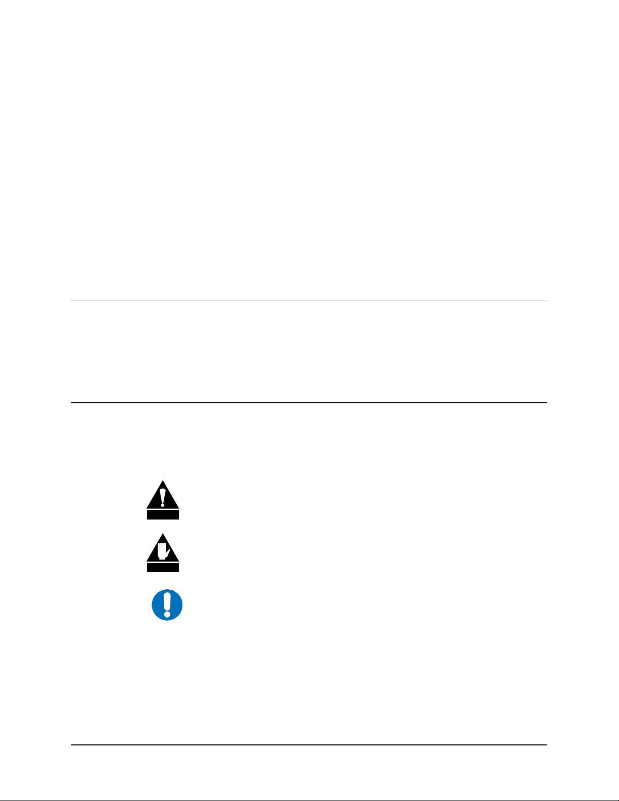
Figure 1-1. SDR-54A Desktop Unit.........................................................................................................................1–2
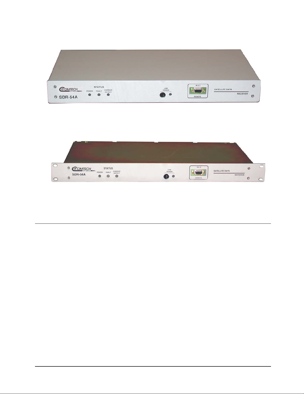
Figure 1-2. SDR-54A Rack Mount Unit ..................................................................................................................1–2
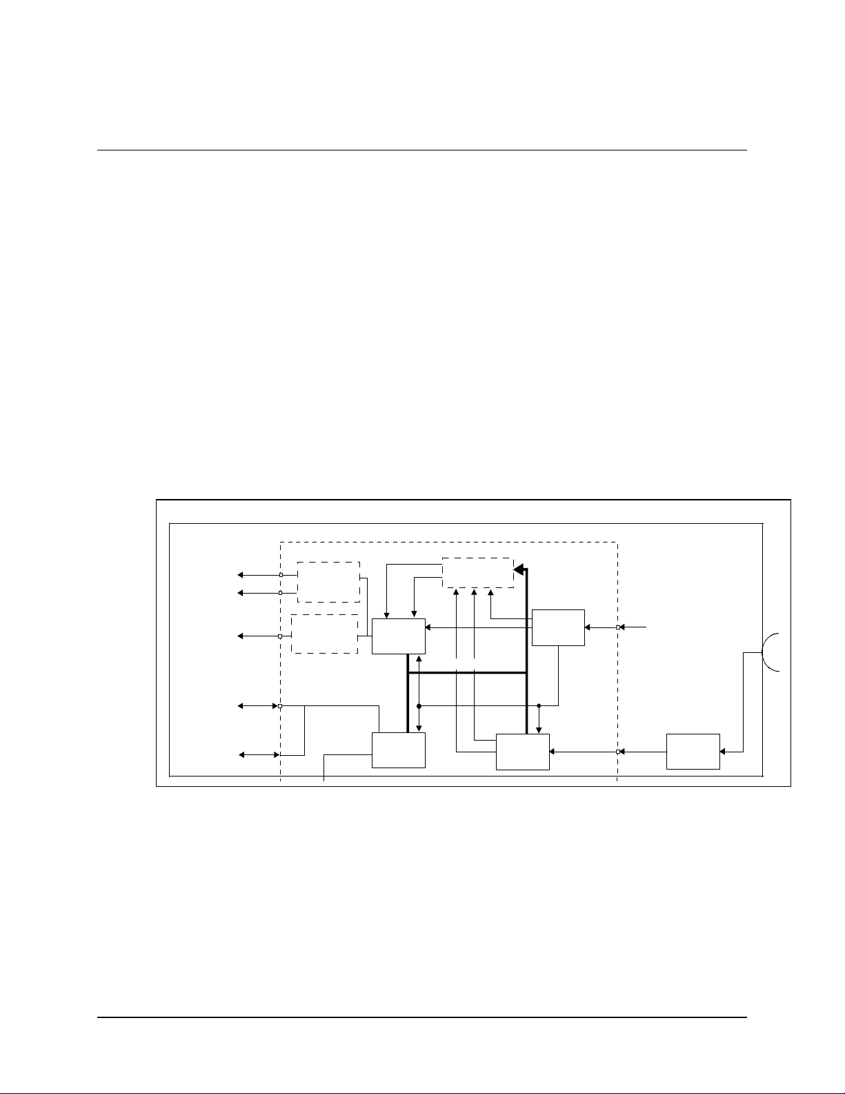
Figure 2-1. Interconnect Diagram ............................................................................................................................2–2
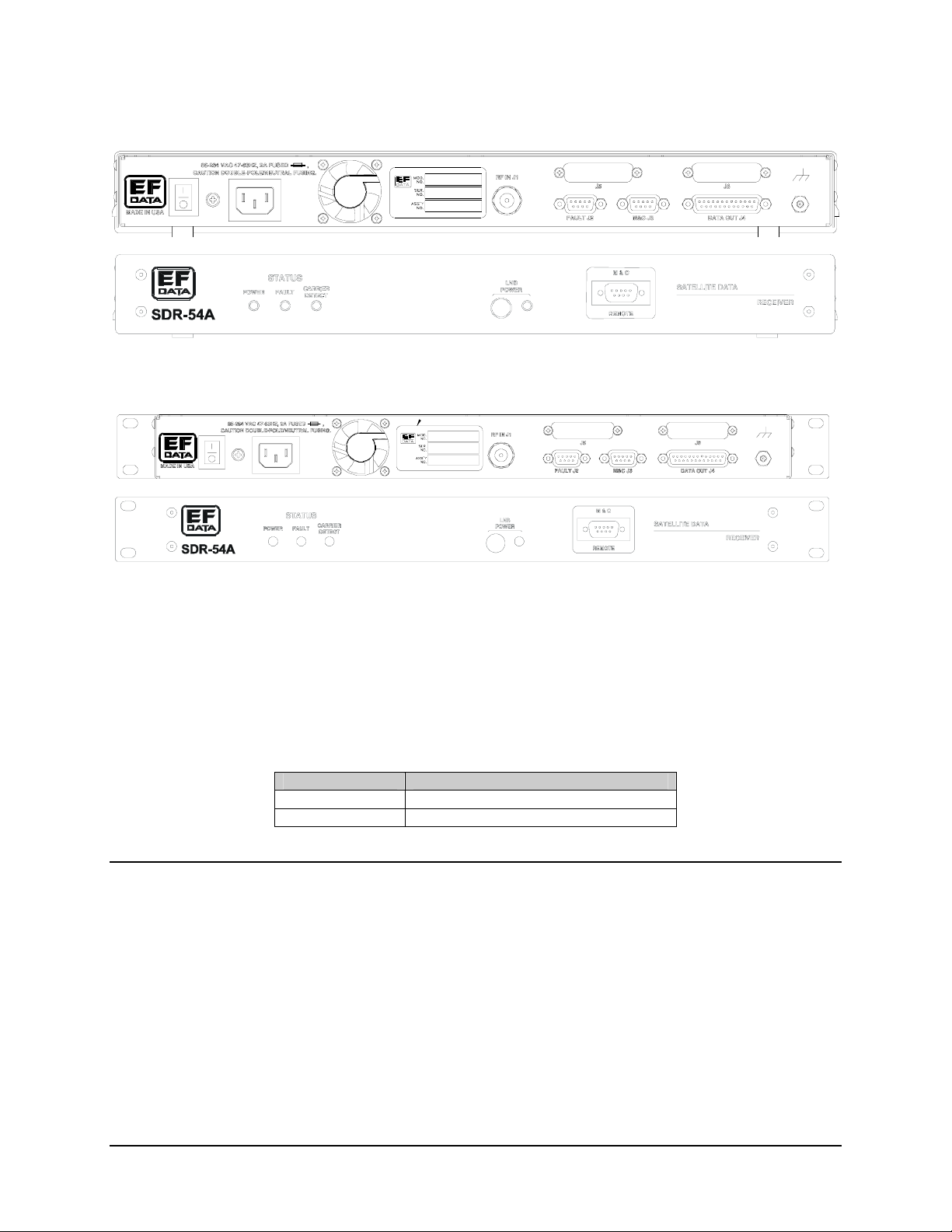
Figure 3-1. SDR-54A Desktop Unit (Rear and Front Panel) ...................................................................................3–2
Figure 3-2. SDR-54A Rack Mount Unit (Rear and Front Panel)............................................................................. 3–2
Figure 3-3. Data Out (J4) Interface Jumpers ............................................................................................................3–4
Figure 3-4. RS-530 Jumper Location (J4)................................................................................................................3–5
Figure 4-1. SDR-54A Desktop Unit (Front Panel)...................................................................................................4–1
Figure 4-2. SDR-54A Rack Mount Unit (Front Panel) ............................................................................................4–1
Figure 5-1. DEMUX 2/4 PCB .................................................................................................................................. 5–2
Figure 5-2. Installation of DEMUX 2/4 Card...........................................................................................................5–4
Figure 5-3. DEMUX 8-Channel PCB.......................................................................................................................5–7
Figure 5-4. Installation of DEMUX 8-Channel Card ...............................................................................................5–9
Figure 6-1. Reed-Solomon Card...............................................................................................................................6–1
Figure 6-2. V.35 Self-Synchronizing Descrambler .................................................................................................. 6–2
Figure 6-3. R-S Code Word Format ......................................................................................................................... 6–3
Figure 6-4. Installation of Reed-Solomon Card (AS/6285)......................................................................................6–5
Figure 6-5. Reed-Solomon Decoder Section Block Diagram...................................................................................6–7
Figure 6-6. BER Performance with Noise, Viterbi Decoder, and Reed-Solomon (Optional).................................. 6–8
Figure 8-1. BPSK and QPSK BER Performance .....................................................................................................8–6
vii
Page 10

SDR-54A Satellite Demodulator Revision 4
Preface MN/SDR54A.IOM
Tables
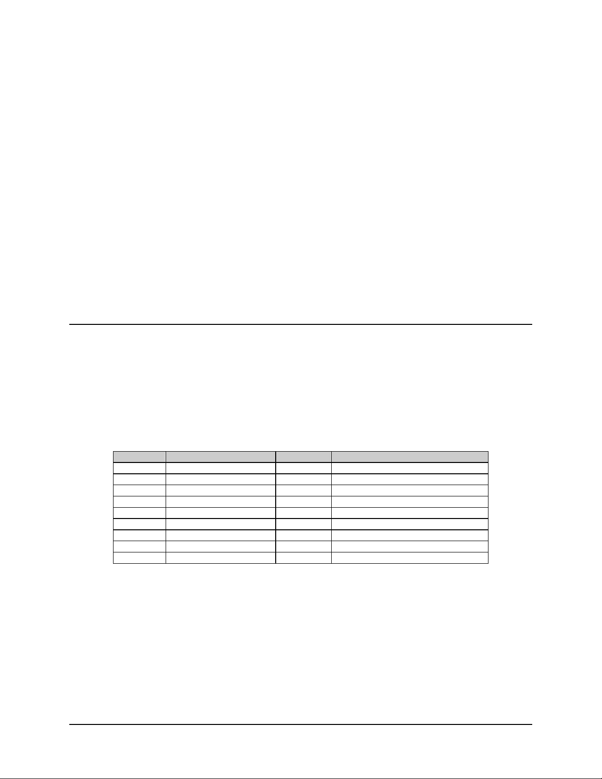
Table 3-1. External Connectors................................................................................................................................3–1
Table 3-2. RF Input (J1) Specification .....................................................................................................................3–2
Table 3-3. Fault Connector 9-Pin D Sub Female .....................................................................................................3–3
Table 3-4. Rear Panel Connector Pinouts................................................................................................................. 3–3
Table 3-5. Front Panel Connector Pinouts................................................................................................................3–4
Table 3-6. Data Interface Connector 25-Pin D Sub..................................................................................................3–5
Table 3-7. Data Interface Connector (RS-232) 25-Pin D Sub.................................................................................. 3–6
Table 3-8. AC Option ............................................................................................................................................... 3–6
Table 3-9. 48 VDC Option .......................................................................................................................................3–7
Table 3-10. 24 VDC Option .....................................................................................................................................3–7
Table 4-1. Indicators.................................................................................................................................................4–2
Table 5-1. Summary of DEMUX Specification .......................................................................................................5–5
Table 5-2. Tributary Data Interface Connector (RS-422) ........................................................................................5–5
Table 5-3. Tributary Data Interface Connector (RS-232) 25-Pin D Sub (Female) ..................................................5–6
Table 5-4. DEMUX 8-Channel Specification .......................................................................................................5–10
Table 5-5. Monitor & Control Additions................................................................................................................5–11
Table 5-6. Tributary Data Interface Connector (J5) ...............................................................................................5–11
Table 5-7. Tributary Data Interface Connector (J6) ...............................................................................................5–12
Table 5-8. Aggregate Data and Clock ....................................................................................................................5–12
Table 6-1. R-S Codes ...............................................................................................................................................6–4
Table 6-2. BER PErformance Curve Data................................................................................................................6–7
Table 6-3. Reed-Solomon Specifications .................................................................................................................6–8
Table 6-4. Interface Connector.................................................................................................................................6–9
Table 8-1. Demodulator Specifications ....................................................................................................................8–1
Table 8-2. Environmental and Physical Specification..............................................................................................8–2
Table 8-3. Digital Data Rates ...................................................................................................................................8–4
Table 8-4. Demodulator and FEC Decoding Types .................................................................................................8–5
Table 8-5. BPSK and QPSK BER Performance.......................................................................................................8–5
Table 8-6. BPSK and QPSK BER Performance.......................................................................................................8–5
Table 8-7. Carrier and Clock Acquisition Time .......................................................................................................8–7
Table 8-8. Monitor and Control Specifications ........................................................................................................8–9
Table 8-9. Aggregate Data/Clock Input and Power Connector (J3).......................................................................8–14
Table 8-10. 8-Channel Demux Specifications........................................................................................................8–14
Table 8-11. Tributary Data Connector (J3) ...........................................................................................................8–15
Table 8-12 Tributary Data Connector (J4) ............................................................................................................8–16
Table 8-13. Aggregate Data/Clock Inpout, Power Connector................................................................................8–17
Table 8-14. Mode and SYNC Connector (JP2)......................................................................................................8–17
Table 8-15. Secondary Demodulator Interface Connector ..................................................................................... 8–17
Table 8-16. Reed-Solomon Specifications .............................................................................................................8–18
viii
Page 11
SDR-54A Satellite Demodulator Revision 4
Preface MN/SDR54A.IOM
Preface
About this Manual
This manual provides installation and operation information for the Comtech EF Data
SDR-54A satellite demodulator. This is a technical document intended for earth station
engineers, technicians, and operators responsible for the operation and maintenance of the
SDR-54A.
Conventions and References Used in this Manual
Cautions and Warnings
CAUTION indicates a hazardous situation that, if not avoided, may result in
minor or moderate injury. CAUTION may also be used to indicate other
CAUTION
WARN ING
IMPORTANT
unsafe practices or risks of property damage.
WARNING indicates a potentially hazardous situation that, if not avoided,
could result in death or serious injury.
IMPORTANT indicates a statement that is associated with the task
being performed. .
ix
Page 12

SDR-54A Satellite Demodulator Revision 4
Preface MN/SDR54A.IOM
Trademarks
Product names mentioned in this manual may be a trademark or registered trademarks of
their respective companies and are hereby acknowledged.
Metric Conversion
Metric conversion information is located on the inside back cover of this manual. This
information will assist the operator in cross-referencing English to Metric conversions.
Related Documents
The following documents are referenced in this manual:
• Comtech EF Data Specification SP/5231, SOS 2/4 Channel Demux
• Comtech EF Data Specification SP/5487 SLRC - Space Link Remote Control
• Comtech EF Data Specification SP/5839 Comtech EF Data 8-Channel Demux
• Comtech EF Data Specification SP/6258 SDM-300A (Reed-Solomon)
• Comtech EF Data Specification SP/6537, SDR-54A L-Band Demodulator
Overview of Changes to Previous Edition
Changes made to Revision 3 include:
Total revision and reformat.
Added FW/5445-1K Verison: 4.2.4
Reporting Comments or Suggestions Concerning this Manual
Comments and suggestions regarding the content and design of this manual will be
appreciated. To submit comments, please contact the Comtech EF Data Customer
Support Department according to the information in the following section.
x
Page 13

SDR-54A Satellite Demodulator Revision 4
Preface MN/SDR54A.IOM
Warranty Policy
This Comtech EF Data product is warranted against defects in material and workmanship
for a period of 1 year from the date of shipment. During the warranty period, Comtech EF
Data will, at its option, repair or replace products that prove to be defective.
For equipment under warranty, the customer is responsible for freight to Comtech EF
Data and all related custom, taxes, tariffs, insurance, etc. Comtech EF Data is responsible
for the freight charges only for return of the equipment from the factory to the customer.
Comtech EF Data will return the equipment by the same method (i.e., Air, Express,
Surface) as the equipment was sent to Comtech EF Data.
Limitations of Warranty
The foregoing warranty shall not apply to defects resulting from improper installation or
maintenance, abuse, unauthorized modification, or operation outside of environmental
specifications for the product, or, for damages that occur due to improper repackaging of
equipment for return to Comtech EF Data.
No other warranty is expressed or implied. Comtech EF Data specifically disclaims the
implied warranties of merchantability and fitness for particular purpose.
Exclusive Remedies
The remedies provided herein are the buyer's sole and exclusive remedies. Comtech EF
Data shall not be liable for any direct, indirect, special, incidental, or consequential
damages, whether based on contract, tort, or any other legal theory.
Disclaimer
Comtech EF Data has reviewed this manual thoroughly in order that it will be an easy-touse guide to your equipment. All statements, technical information, and recommendations
in this manual and in any guides or related documents are believed reliable, but the
accuracy and completeness thereof are not guaranteed or warranted, and they are not
intended to be, nor should they be understood to be, representations or warranties
concerning the products described. Further, Comtech EF Data reserves the right to make
changes in the specifications of the products described in this manual at any time without
notice and without obligation to notify any person of such changes.
If you have any questions regarding your equipment or the information in this manual,
please contact the Comtech EF Data Customer Support Department.
xi
Page 14

SDR-54A Satellite Demodulator Revision 4
Preface MN/SDR54A.IOM
This page is intentionally left blank.
xii
Page 15

Chapter 1. Introduction
This chapter describes the SDR-54A satellite demodulator, hereinafter referred to as
“the demodulator.”
Two versions of the SDR-54A are available:
• Desktop (Figure 1-1)
• Rack Mount (Figure 1-2)
1.1 Demodulator Functions
For the purposes of this document, a demodulator will consist of a device having the
following functions:
• Perform filtered QPSK or BPSK demodulation from carriers of variable
frequencies/amplitudes.
• Decode the data.
• Descramble the data.
• Provide Terrestrial data interface.
• Provide Monitor and Control interface for remote operation.
• Maintain full functionality of SDM-51, SDM-52, and all their respective
configurations.
1–1
Page 16
SDR-54A Satellite Demodulator Revision 4
Introduction MN/SDR54A.IOM
Figure 1-1. SDR-54A Desktop Unit
1.2 Overview
The demodulator provides all necessary functions for accepting L-Band digital data
transmissions, extracting the data, and providing it to the user in a standard serial data
format.
The demodulator is composed of four units:
♦ L-Band digital demodulator
♦ DEMUX (optional)
♦ L-Band low noise block (LNB) converter (required)
♦ Reed-Solomon (optional)
The demodulator is available as either a desktop or rack mount unit. The demodulator may
be located away from the LNB, provided the interconnecting cable losses do not reduce
the signal to below the minimum discernible level of the demodulator (typically
30 dB of loss, dependent on the receive signal level).
The demodulator provides all necessary functions for converting an RF modulated data
carrier input into a digital synchronous data output.
Figure 1-2. SDR-54A Rack Mount Unit
1–2
Page 17

SDR-54A Satellite Demodulator Revision 4
A f
Introduction MN/SDR54A.IOM
The LNB converter is mounted directly to the antenna and preserves received signal-tonoise while providing gain and frequency down conversion. This feature minimizes signal
degradation between the antenna site and demodulator. An appropriate LNB must be used
in order to properly operate the demodulator. LNB primary power is provided by the
demodulator via the coaxial signal interconnect. See Chapter 8 for LNB specification
information.
ully compatible LNB is available from Comtech EF Data. Contact Comtech EF
IMPORTANT
Data Customer Support representative for more information.
L-Band input frequencies are tunable from 950 to 1550 MHz, in graduated steps of
10 kHz. The demodulator will lock to a carrier within the frequency stability range of the
receive system (± 500 kHz), and will perform coherent detection for QPSK and BPSK
modulation.
Forward Error Correction (FEC) is provided by the demodulator’s integrated Viterbi
decoder, which can support 1/2, 3/4, and 7/8 rate coding, along with the optional
Reed-Solomon.
Digital data output is selectable between synchronous RS-232 or RS-422 format. Data
rates from 4.8 to 1250 kbps for BPSK and 9.6 to 4000 kbps for QPSK. The demodulator is
compatible with the following:
• INTELSAT open network filtering
• Comtech EF Data closed network filtering
• SDM-51, -52
Monitor and control of the demodulator is provided by a user-accessible RS-232 serial
port. Once configured, power may be removed for at least 1 year and reapplied without
loss of configuration.
The demodulator incorporates features for remote configuration over the satellite channel
using Comtech EF Data’s Space Link Remote Control (SLRC) protocol.
For more information about the SLRC, refer to the Comtech EF Data Space Link Remote
Control System User’s Guide.
Provisions for optional demultiplexers are as follows:
• Option 1: Synchronous/symmetrical DEMUX 2- or 4-channel. Maximum tributary
data rates of :
1–3
Page 18

SDR-54A Satellite Demodulator Revision 4
Introduction MN/SDR54A.IOM
128 kbps in the 2-channel mode.
64 kbps in the 4-channel mode.
• Option 2: Synchronous/asymmetrical DEMUX 8-channel demultiplexer with
maximum tributary data rate of 4000.0 kbps.
Notes:
1. When using the optional DEMUX 2/4-daughter card, the data output will be in
RS-422 format only.
2. When using the optional DEMUX 8-Channel daughter card, the data output is
software selectable to RS-422 or RS-232.
Refer to Chapter 5 for additional information about DEMUX options.
1.3 Options
• Rack mounted or desktop configurations
• 48 VDC input power
• 24 VDC input power
• 2- or 4-channel synchronous DEMUX (SP/5231 SOSOFT)
• 4- or 8-channel synchronous DEMUX (SP/5839 Comtech EF Data)
• Reed-Solomon Concatenated Codec IESS 308/309 (SP/6285)
1.4 New in this Revision
Incorporated FW/5445-1K, version 4.2.4.
Replaced company name to Comtech EF Data.
1–4
Page 19

This chapter provides unpacking, installation instructions.
2.1 Unpacking
The demodulator and manual are packaged in pre-formed reusable cardboard cartons
containing foam spacing for maximum shipping protection.
To remove the unit from the box, proceed as follows:
CAUTION
1. Cut the tape at the top of the carton, where it is labeled “OPEN THIS END.”
2. Lift out the cardboard/foam spacer covering the demodulator.
3. Remove the demodulator, manual, and power cord from the carton.
4. Save the packing material for reshipment.
5. Inspect the equipment for damage incurred during shipment.
6. Ensure the shipment is complete by checking the equipment against the packing
list shipped with the equipment.
7. Refer to Section 2.2 for system installation instructions.
Chapter 2. Installation
To avoid damage to the unit, do not use any cutting tool, which will extend
more than 1 inch into the container.
2–1
Page 20
SDR-54A Satellite Demodulator Revision 4
Installation MN/SDR54A.IOM
2.2 System Installation
Note: The demodulator is configured at the factory. Use the remote control interface on the
front or rear panel to alter the configuration. For information on configuration and remote
control, refer to Appendix A.
After unpacking the system as outlined in Section 2.1, install the system as follows:
1. Attach an LNB converter to the antenna and connect one end of the
LNB/demodulator interconnecting cable to the LNB coaxial output.
2. Refer to Figure 2-1 prior to cabling the demodulator, the output data port must be
configured for the appropriate interface: RS-232 or RS-422.
a. The interface is configured as RS-422 at the factory.
b. If RS-232 is required, remove the demodulator cover, locate the jumpers of
JP8 (directly behind the DATA OUT connector), and reposition , as outlined
in Chapter 3.
CLK/
DATA
OUT
EIA-422 OR
EIA-232
CLK/
DATA
OUT
EIA-422 OR
EIA-232
REMOTE
SERIAL
INTERFACE
EIA-232
FRONT PANEL
M&C REMOTE
SERIAL INTERFACE
EIA-232
J6
J5
J4
J3
DEMUX
OPTION EFD
8-CHANNEL
DEMUX
OPTION EFD
24-CHANNEL
DATA
INTERFACE
MONITOR
&
CONTROL
CLK
REED-SOLOMON
OPTION
COMMAND BUS
DATA
CLK
DEMOD
CODE
POWER
SUPPLY
+24 VDC
L-BAND
IF INPUT
1.5A
90 TO 264 VAC:
47 TO 63 Hz
J1
950 TO 1550 MHz
-30 TO -80 dBm
Figure 2-1. Interconnect Diagram
3. Connect the AC power cord and turn on the demodulator. The front panel
POWER indicator should illuminate and the FAULT indicator should be off.
4. Configure the demodulator. Refer to Appendix A for specific demodulator
configuration information.
L-BAND
LNB
WAVEGUIDE
2–2
Page 21

SDR-54A Satellite Demodulator Revision 4
Installation MN/SDR54A.IOM
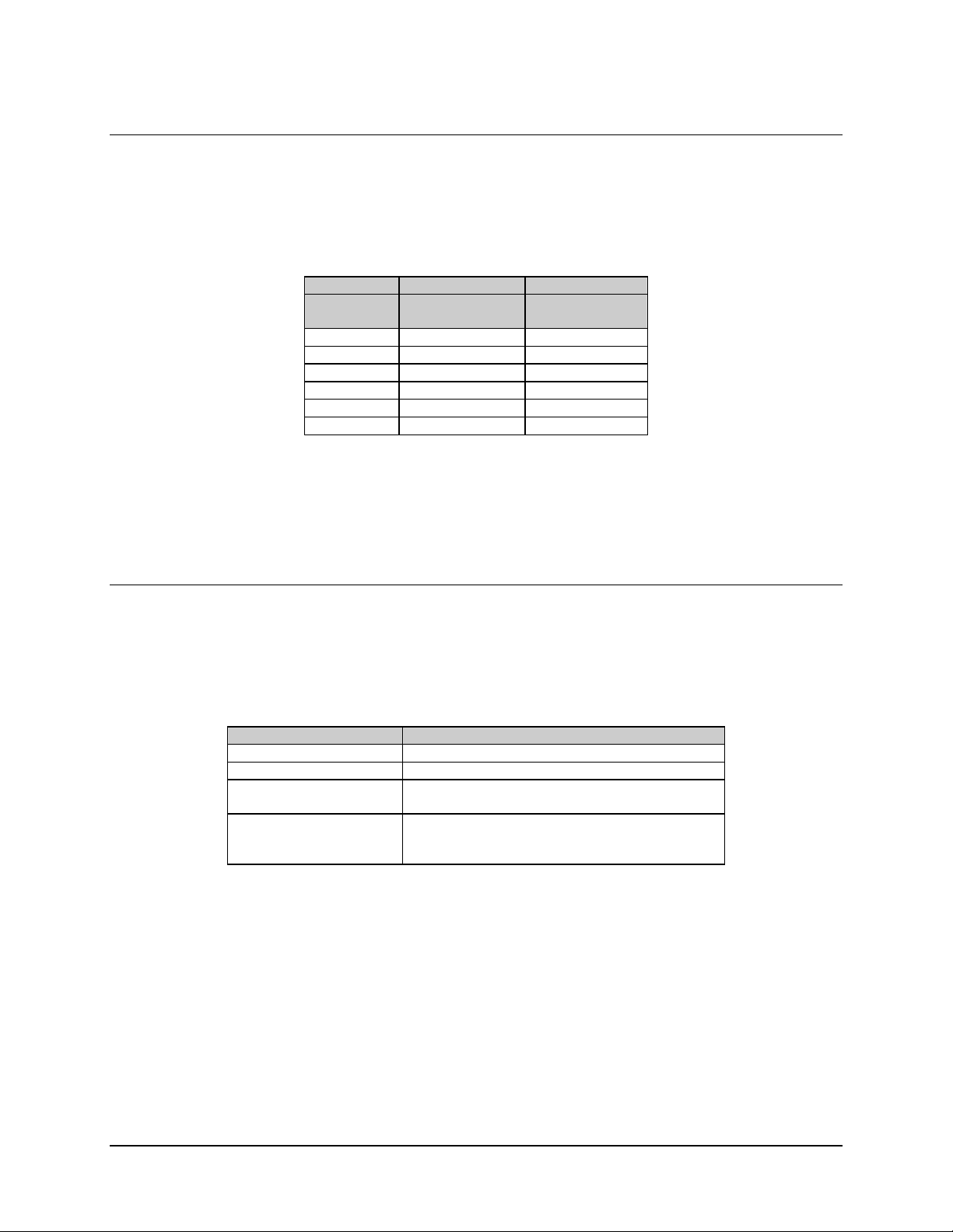
Demodulation frequency, rate, and reacquisition time are defined as follows:
Term Definition
Frequency Carrier frequency of the desired channel
Rate Data rate of the desired channel
Reacquisition Time Time delay from incidental carrier loss until the modem initiates
carrier search
Note: The above values, when set, are retained by the demodulator until changed by the
user. Once the demodulator is configured and operating, the terminal is no longer
required.
Once configured, the demodulator will perform an acquisition search for the desired
channel. If a signal is present at a sufficient level, the CARRIER DETECT indicator on
the front panel will illuminate. Data will be present at the DATA OUT serial port, if the
detected signal can be demodulated and decoded.
2–3
Page 22

SDR-54A Satellite Demodulator Revision 4
Installation MN/SDR54A.IOM
Notes:
_______________________________________________________________________
_______________________________________________________________________
_______________________________________________________________________
_______________________________________________________________________
_______________________________________________________________________
_______________________________________________________________________
_______________________________________________________________________
_______________________________________________________________________
_______________________________________________________________________
_______________________________________________________________________
_______________________________________________________________________
_______________________________________________________________________
_______________________________________________________________________
_______________________________________________________________________
_______________________________________________________________________
_______________________________________________________________________
_______________________________________________________________________
_______________________________________________________________________
_______________________________________________________________________
_______________________________________________________________________
_______________________________________________________________________
_______________________________________________________________________
_______________________________________________________________________
_______________________________________________________________________
_______________________________________________________________________
_______________________________________________________________________
_______________________________________________________________________
_______________________________________________________________________
_______________________________________________________________________
_______________________________________________________________________
_______________________________________________________________________
_______________________________________________________________________
_______________________________________________________________________
_______________________________________________________________________
_______________________________________________________________________
_______________________________________________________________________
_______________________________________________________________________
_______________________________________________________________________
_______________________________________________________________________
_______________________________________________________________________
2–4
Page 23
Chapter 3. External Connectors
This chapter provides a description of external connections.
3.1 External Connections
Connections between the demodulator and other equipment are made through external
connectors. These connectors are listed in Table 3-1, and their locations are shown in
Figure 3-1 and Figure 3-2. The use of each connector is described in the following
paragraphs.
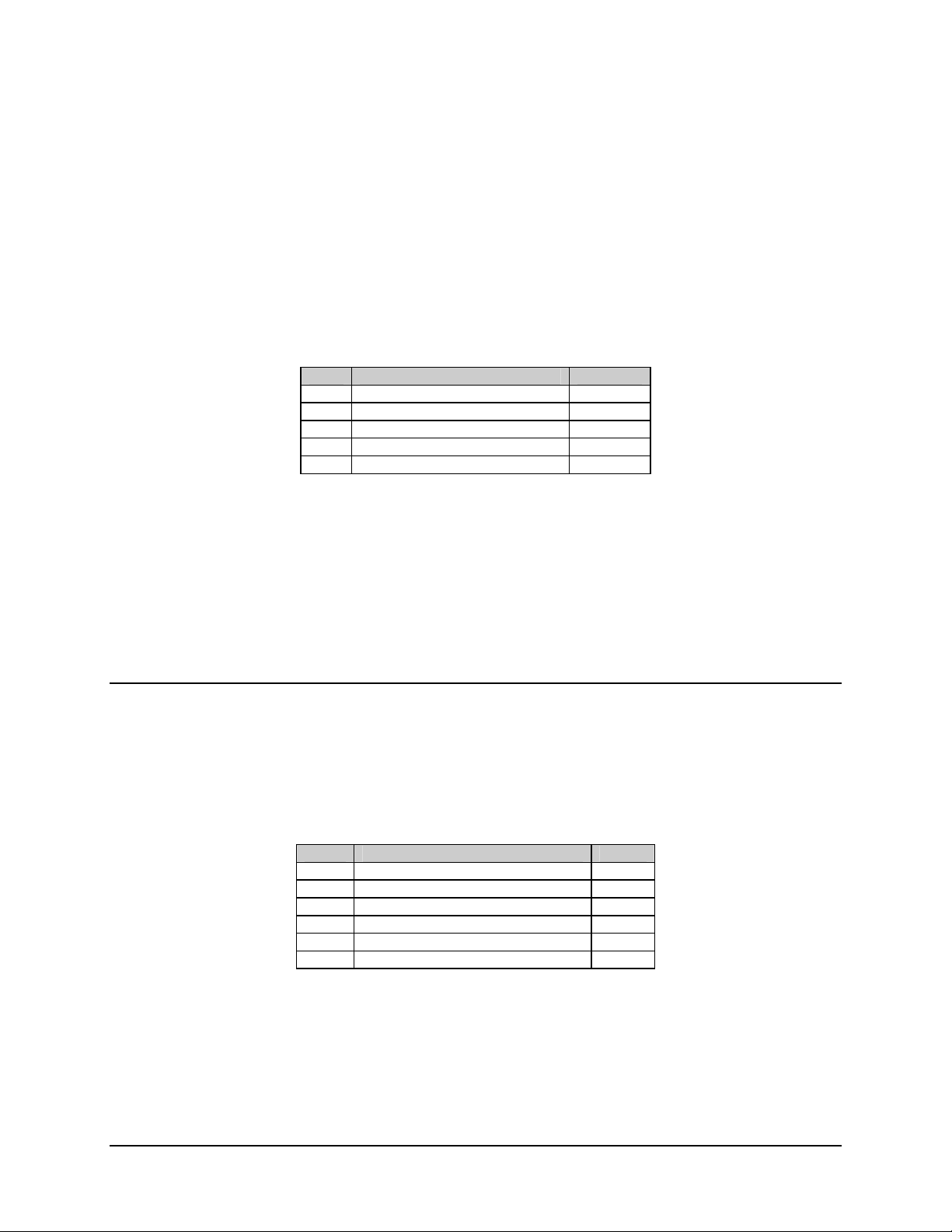
Table 3-1. External Connectors
Ref. Desig. Name Type Function
J1 RF INPUT F coax LNB input/LNB power
J2 FAULT 9-pin D External Fault Status
J3 M&C 9-pin D Configuration and Status (RS-232)
J4 DATA OUT (RX Data) 25-pin D RS-232 or RS-422 Selectable
*J5 DEMUX T1 through T4 25-pin D DEMUX Outputs T1 through T4
*J6 DEMUX T5 through T8 25-pin D DEMUX Outputs T5 through T8
None M&C REMOTE 9-pin D Remote Configuration and Status
None PRIME POWER Standard AC Power Input
None GND #10-32 Chassis Ground
*Note: J5 and J6 are optional.
3–1
Page 24
SDR-54A Satellite Demodulator Revision 4
External Connectors MN/SDR54A.IOM
Figure 3-1. SDR-54A Desktop Unit (Rear and Front Panel)
Figure 3-2. SDR-54A Rack Mount Unit (Rear and Front Panel)
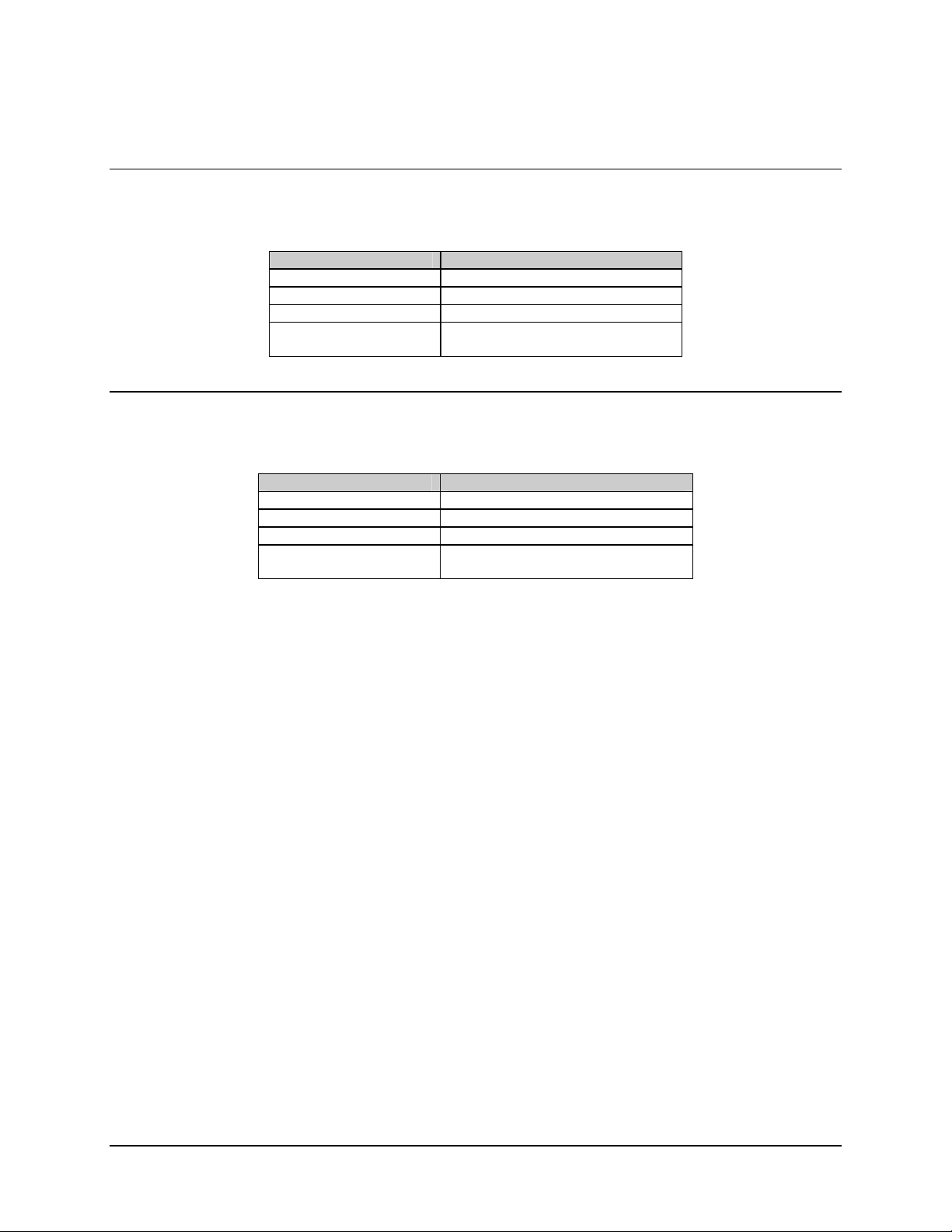
3.1.1 RF Input (J1)
Refer to Table 3-2 for RF Input (J1) specification.
Table 3-2. RF Input (J1) Specification
Parameter Specification
Connector type
Return loss -8 dB or greater from 950 to 1550 MHz
3.1.1.1 L-Band RF Input
This is a type F female coaxial connector for signal input to the demodulator unit from the
LNB. This connector also provides DC power to the LNB along the center conductor, with
the shield as the return.
F Type (Female) 75Ω
3–2
Page 25
SDR-54A Satellite Demodulator Revision 4
External Connectors MN/SDR54A.IOM
3.1.2 Fault Connector (J2)
A fault connection occurs when any of the indicators in the demodulator fault status
command show a fault condition.
Refer to Table 3-3 for Fault connector specifications.
Table 3-3. Fault Connector 9-Pin D Sub Female
Pin # Signal Function Name
1 Ground GND
2 FORM C Normally Closed FCNC
3 FORM C Common FCC
4 FORM C Normally Open FCNO
8 TTL OPEN Collector TTL-OC
Note: A connection between FCNO (pin 4) and FCC (pin 3) indicates no fault.
3.1.3 M&C Port (J3)
The M&C port enables the user to exercise the control and status commands listed in
Appendix A. The port is accessible from either the front or rear panel. Only one of these
ports may be used at a time.
3.1.3.1 Rear Panel Connector Pinout
The M&C port is provided on a 9-pin female D connector. Screw locks are provided for
mechanical security of the mating connector. This connector is a DCE interface. Pinouts are
described in Table 3-4:
Table 3-4. Rear Panel Connector Pinouts
Pin # Signal Function Name
2 Receive data output (RS-232-C) RX
3 Transmit data input (RS-232-C) TX
5 Ground GND
*7 Request to send input (RS-232-C) RTS
*8 Clear to send output (RS-232-C) CTS
9 AGC Analog 0 to 5 VDC at 10 mA AGC
*Note: RTS and CTS are internally connected together.
3–3
Page 26
SDR-54A Satellite Demodulator Revision 4
External Connectors MN/SDR54A.IOM
3.1.3.2 Front Panel Connector Pinout
The M&C port is provided on a 9-pin female D connector. Screw locks are provided for
mechanical security of the mating connector. This connector is a DCE interface. Pinouts are
described in Table 3-5:
Table 3-5. Front Panel Connector Pinouts
Pin # Signal Function Name
1 +5 VDC at 100 mA +5
2 Receive data output (RS-232-C) RX
3 Transmit data input (RS-232-C) TX
5 Ground GND
*7 Request to send input (RS-232-C) RTS
*8 Clear to send output (RS-232-C) CTS
9 AGC Analog 0 to 5 VDC at 10 mA AGC
*Note: RTS and CTS are internally connected together.
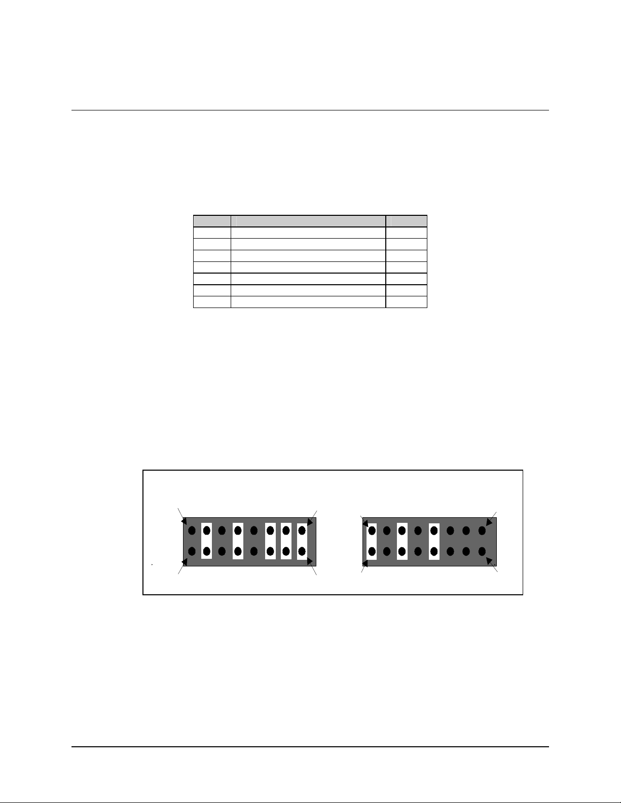
3.1.4 Data Out Connector (J4) Interface Type Jumpers
The J4 port is the interface between the demodulator and the user’s terrestrial equipment.
This port may be configured internally as an RS-232 or RS-422 interface, as required, by
removing the modem cover and positioning the jumpers of JP3 (Figure 3-3), as follows:
2216 16
OPEN
1
Figure 3-3. Interface Type Jumper Location (JP3)
Notes:
1. If optional DEMUX 2/4 PCB is installed, position jumpers for RS-422 operation.
2. If optional DEMUX 8-Channel PCB is installed, refer to Chapter 5.
OPEN
JUMP
JUMP
EIA-422
OPEN
JUMP
JUMP
JUMP
15
1
OPEN
JUMP
JUMP
OPEN
OPEN
JUMP
EIA-232
OPEN
OPEN
15
3–4
Page 27
SDR-54A Satellite Demodulator Revision 4
External Connectors MN/SDR54A.IOM
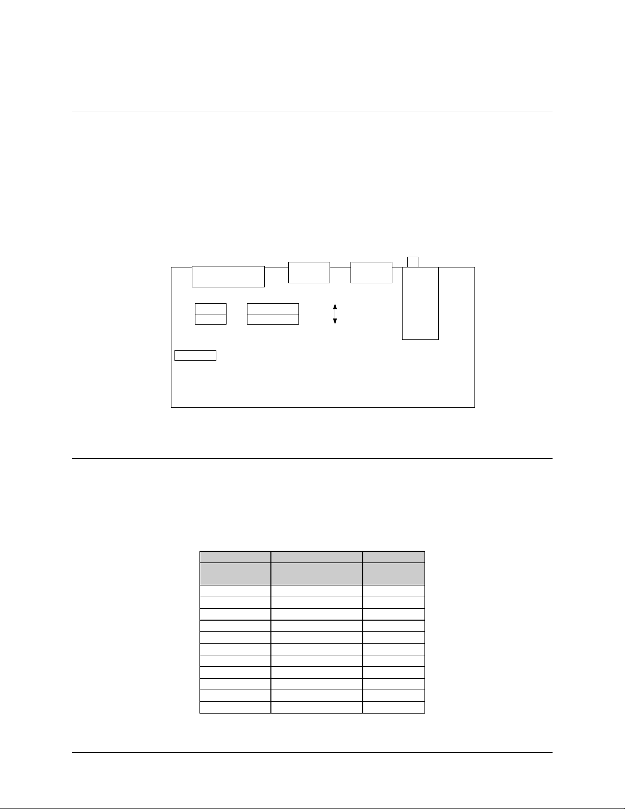
3.1.4.1 Data Out Connector (J4) Pinout Jumper Location
The pinout configuration for the Data Out Connector (J4) can be set for:
• Standard (SDR-54A, SDM-51/-52 compatible)
• EIA-530
This is accomplished by removing the cover and positioning the jumper blocks at JP4 and
JP5 to the appropriate positions. Refer to Figure 3-4 for EIA-530 jumper location.
J4
JP4
Pinout Jumper Blocks
JP3
RS232/
RS422
JP5
Figure 3-4. Data Pinout Jumper Location (JP4/JP5)
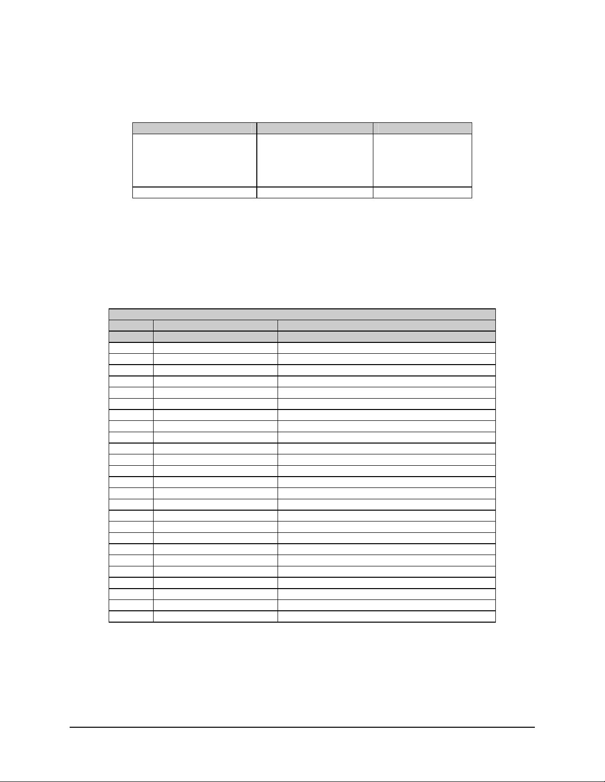
3.1.4.2 Data Out Connector (J4)
Refer to Table 3-6 for data interface connector specifications. This table reflects a
non-DEMUX operation.
Table 3-6. Data Interface Connector 25-Pin D Sub
Standard RS-422 EIA-530
DB25M (J4)
Pin #
3 RX Data A (-) 3
4 RX Data B (+) 16
17 RX Clock A (-) 17
18 RX Clock B (+) 9
CD/RR A (-) 8
20 CD/RR B (+) 10
DM A (-) 6
DM B (-) 22
DF 21
7 SIG GND 7
SHLD GND 1
Signal Name
Standard
EIA-530
DB25M (J4)
Pin#
3–5
Page 28
SDR-54A Satellite Demodulator Revision 4
External Connectors MN/SDR54A.IOM
3.1.4.3 Data Out Connector (J4)
Refer to Table 3-7 for data interface connector specifications.
Table 3-7. Data Interface Connector (EIA-232)
25-Pin D Sub
Standard EIA-432 EIA-530
DB25M (J4)
Pin #
3 RX Data 3
17 RX Clock 17
8 CD/RR 8
N/A DM 6
7 SIG GND 7
N/A SHLD GND 1
Signal Name
DB25M (J4)
Pin #
Note: Table 3-7 reflects non-DEMUX operation.
3.1.5 Power Entry
3.1.5.1 AC Option
The AC power is supplied to the demodulator by a standard, detachable, non-locking,
3-prong power cord. Refer to Table 3-8 for the required specifications.
Parameter Specification
Connector Type I.E.C.
Input Power 40W maximum.
Input Voltage 90 to 132VAC, or 175 to 264 VAC. Unit switches
Fuse Protection
(internal on power supply)
Table 3-8. AC Option
ranges automatically.
3.15A slo-blo.
Line and neutral fusing.
5mm type fuse.
3–6
Page 29
SDR-54A Satellite Demodulator Revision 4
External Connectors MN/SDR54A.IOM
3.1.5.2 48 VDC Option
Table 3-9. 48 VDC Option
Parameter Specification
Connector Type 20A 3-way screw-type terminal block.
Input Power 40W maximum.
Input Voltage 46 to 50 VDC.
Fuse Protection
(internal on power supply)
2A slo-blo.
3.1.5.3 24 VDC Option
Table 3-10. 24 VDC Option
Parameter Specification
Connector Type 20A 3-way screw-type terminal block.
Input Power 40W maximum.
Input Voltage 23 to 25 VDC.
Fuse Protection
(Internal on power supply)
2A slo-blo.
3.1.6 Ground (GND)
A #10-32 stud is available on the rear for connecting a common chassis ground among all
of the equipment.
Note: The safety ground is provided through the AC power connector.
3–7
Page 30

SDR-54A Satellite Demodulator Revision 4
External Connectors MN/SDR54A.IOM
Notes:
_______________________________________________________________________
_______________________________________________________________________
_______________________________________________________________________
_______________________________________________________________________
_______________________________________________________________________
_______________________________________________________________________
_______________________________________________________________________
_______________________________________________________________________
_______________________________________________________________________
_______________________________________________________________________
_______________________________________________________________________
_______________________________________________________________________
_______________________________________________________________________
_______________________________________________________________________
_______________________________________________________________________
_______________________________________________________________________
_______________________________________________________________________
_______________________________________________________________________
_______________________________________________________________________
_______________________________________________________________________
_______________________________________________________________________
_______________________________________________________________________
_______________________________________________________________________
_______________________________________________________________________
_______________________________________________________________________
_______________________________________________________________________
_______________________________________________________________________
_______________________________________________________________________
_______________________________________________________________________
_______________________________________________________________________
_______________________________________________________________________
_______________________________________________________________________
_______________________________________________________________________
_______________________________________________________________________
_______________________________________________________________________
_______________________________________________________________________
_______________________________________________________________________
_______________________________________________________________________
_______________________________________________________________________
_______________________________________________________________________
3–8
Page 31

This chapter describes the operation of the indicators and controls located on the unit.
4.1 Front Panel
Refer to Figure 4-1 and Figure 4-2 for front panel views of the Desktop and Rack Mount
versions of the demodulator.
Figure 4-1. SDR-54A Desktop Unit (Front Panel)
Chapter 4. Operation
Figure 4-2. SDR-54A Rack Mount Unit (Front Panel)
4–1
Page 32

SDR-54A Satellite Demodulator Revision 4
Operation MN/SDR54A.IOM
4.1.1 Indicators
There are three LED indicators for monitoring demodulator status and one LED indicator
for monitoring external features, see Table 4-1:
Table 4-1. Indicators
Monitoring Demodulator Features
Feature Color Description
POWER Green Indicates that power is applied to the unit.
FAULT Red Indicates that a demodulator fault condition exists.
CARRIER
DETECT
LNB POWER Green/Red Indicates LNB power enabled/LNB Fault.
Note: Due to the sensitivity of the SDR-54A tuner, a Carrier Detect indication may be
seen at some frequencies without the LNB attached.
Green Indicates carrier presence.
Monitoring External Features
4.1.2 LNB Power
LNB power is controlled by a pushbutton switch. An LED indicates when the LNB
power is enabled. The power (+24 VDC) is supplied along the center conductor of the IF
input coaxial cable.
• If the current drawn by the LNB is within the established limits, the LED will
illuminate GREEN.
• If the current drawn by the LNB is out of the established limits, the LED will
illuminate RED.
Refer to Chapter 8 for additional information.
4.2 Configuration Setup
The SDR-54A must be configured using a remote terminal. For information on remote
control operation, refer to Appendix A.
4–2
Page 33

SDR-54A Satellite Demodulator Revision 4
Operation MN/SDR54A.IOM
4.3 Cooling Fan
The SDR-54A uses a 12VDC fan to provide adequate cooling of the unit. Be sure to
provide sufficient clearance (1 inch minimum) on the back and sides of the unit for
proper ventilation.
Units manufactured prior to May 1, 2002 incorporated a temperature control circuit for
fan operation. This control circuit would activate fan operation when the unit reached a
certain temperature and then shut the fan off when the unit cooled. Units built after May
1, 2002 have the control circuit removed thus allowing constant fan operation, resulting
in a more stable internal temperature. Any units sent in to CEFD for repair also will have
the control circuit bypassed.
4–3
Page 34

SDR-54A Satellite Demodulator Revision 4
Operation MN/SDR54A.IOM
Notes:
_______________________________________________________________________
_______________________________________________________________________
_______________________________________________________________________
_______________________________________________________________________
_______________________________________________________________________
_______________________________________________________________________
_______________________________________________________________________
_______________________________________________________________________
_______________________________________________________________________
_______________________________________________________________________
_______________________________________________________________________
_______________________________________________________________________
_______________________________________________________________________
_______________________________________________________________________
_______________________________________________________________________
_______________________________________________________________________
_______________________________________________________________________
_______________________________________________________________________
_______________________________________________________________________
_______________________________________________________________________
_______________________________________________________________________
_______________________________________________________________________
_______________________________________________________________________
_______________________________________________________________________
_______________________________________________________________________
_______________________________________________________________________
_______________________________________________________________________
_______________________________________________________________________
_______________________________________________________________________
_______________________________________________________________________
_______________________________________________________________________
_______________________________________________________________________
_______________________________________________________________________
_______________________________________________________________________
_______________________________________________________________________
_______________________________________________________________________
_______________________________________________________________________
_______________________________________________________________________
_______________________________________________________________________
_______________________________________________________________________
_______________________________________________________________________
_______________________________________________________________________
_______________________________________________________________________
_______________________________________________________________________
_______________________________________________________________________
4–4
Page 35

Chapter 5. DEMUX Option
This chapter describes the two DEMUX daughter card options that are supported by the
SDR-54A.
5.1 DEMUX Overview
The SDR-54A DEMUX options, hereafter referred to as “the DEMUX 2/4” or the
“DEMUX 8-Channel”, are “daughter card” plug-in options for the demodulator.
The SDR-54A supports two DEMUX daughter card options:
• DEMUX 2/4
• DEMUX 8-Channel
The DEMUX 2/4 converts a single, aggregate-input data stream into two or four tributary
output data streams. Aggregate-input data consists of interleaved tributary data and
synchronization overhead added by a remote uplink multiplexer.
The DEMUX 2/4 is designed to operate in a 2- or 4-channel broadcast multiplexer
system, and to inter-operate with Comtech EF Data’s MUX24 multiplexer.
For more information on the MUX24, refer to Comtech EF Data Specification SP/5231
SOSOFT 2/4 Channel Demux.
The DEMUX 8-Channel converts the aggregate data stream into one to eight tributaries.
Aggregate input data consists of interleaved tributary data and synchronization overhead
added by a remote uplink multiplexer.
The DEMUX 8-Channel is designed to operate in a 1- to 8-channel broadcast multiplexer
system, and to inter-operate with Comtech EF Data’s 8-Channel multiplexer.
For more information on the DEMUX 8-Channel multiplexer, refer to the Comtech EF
Data Specification SP/6285 SDM-300A RX Reed-Solomon.
5-1
Page 36

SDR-54A Satellite Demodulator Revision 4
DEMUX Option MN/SDR54A.IOM
5.2 DEMUX 2/4-Channel (Option)
5.2.1 Description
The (AS/5231) DEMUX 2/4 PCB, shown in Figure 5-1, is an option which plugs into the
demodulator motherboard.
Figure 5-1. DEMUX 2/4 PCB
Note: The shunt on JP2 should always be positioned between pins 2 and 3.
5-2
Page 37

SDR-54A Satellite Demodulator Revision 4
DEMUX Option MN/SDR54A.IOM
5.2.2 Installation
Install the DEMUX 2/4 card as follows:
1. Remove the six 6-32 pan head screws (three on each side) which secure the cover
to the chassis.
Note: The cover and chassis are held together by flange tabs located on the top
and bottom surfaces.
2. Remove the cover from the chassis as follows:
a. Two extraction slots near the front of the unit are located on the top surface.
b. Separate the chassis and cover by placing a screw driver into the extraction
slots and twisting.
Note: To remove the chassis from the cover, gently pry the chassis and cover
away from each other.
c. A ribbon connection between the front panel and the main PCB will allow
for the removal of the chassis without disconnecting the front panel.
Use Electrostatic Discharge (ESD) precautionary procedures when
touching, removing, or inserting PCBs.
CAUTION
3. Locate the DEMUX mounting location at the right rear of the demodulator PCB
as shown in Figure 5-2.
4. Carefully remove the DEMUX PCB from the anti-static bag and plug it into
position on the PCB as shown in Figure 5-2.
Be careful to not bend or break any of the DEMUX mounting pins
when installing the PCB.
CAUTION
5-3
Page 38

SDR-54A Satellite Demodulator Revision 4
DEMUX Option MN/SDR54A.IOM
Figure 5-2. Installation of DEMUX 2/4 Card
Do not overtighten the screws. Damage to the DEMUX mounting
pins could result.
CAUTION
5. Install three 2-56 screws and split lockwashers.
6. Install the top chassis as follows:
a. Coat the 6 securing screws with a small amount of Loctite 425, instant
adhesive.
b. Position the top chassis in place, ensuring the tabs are aligned and secure.
c. Press the top chassis into the bottom while ensuring the LED lights tubes and
push-button switches are aligned.
Do not overtighten the 6 securing screws. Damage to the top chassis
can occur.
CAUTION
d. Secure the top chassis with the 6 screws, using a 5/64 hex driver.
5-4
Page 39

SDR-54A Satellite Demodulator Revision 4
DEMUX Option MN/SDR54A.IOM
5.2.3 DEMUX 2/4-Channel Specification
Table 5-1. Summary of DEMUX Specification
Parameter Specification
DEMUX Type Synchronous, symmetrical data rates on all tributaries
Tributary Channels 2 or 4, automatic detection
Tributary Data Interface RS-422 or RS-232, 25-pin D-sub
Tributary Data Rate:
4-Channel Mode
2-Channel Mode
Clock
Synchronization Indicator TTL, on interface connector (1 = SYNC)
Mode Indicator TTL, on interface connector (0 = 2 channel mode)
9.6 to 64.0 kbit/s, 32/129 of aggregate channel
9.6 to 128.0 kbit/s, 64/129 of aggregate channel
50% duty cycle, ± 10%, phase locked to aggregate channel
5.2.4 Tributary Data Interface Connector RS-422 (J4)
Table 5-2. Tributary Data Interface Connector (RS-422)
Rear Panel 25-Pin D Connector
J4 DEMUX T1-4
Pin # Circuit Description
1 RXDaT1 Trib #1 data inverting output
14 RXDbT1 Trib #1 data non-inverting output
2 RXCaT1 Trib #1 clock inverting output
15 RXCbT1 Trib #1 clock non-inverting output
6 RXDaT2 Trib #2 data inverting output
19 RXDbT2 Trib #2 data non-inverting output
21 RXCaT2 Trib #2 clock inverting output
9 RXCbT2 Trib #2 clock non-inverting output
22 RXDaT3 Trib #3 data inverting output
10 RXDbT3 Trib #3 data non-inverting output
23 RXCaT3 Trib #3 clock inverting output
11 RXCbT3 Trib #3 clock non-inverting output
24 RXDaT4 Trib #4 data inverting output
12 RXDbT4 Trib #4 data non-inverting output
15 RXCaT4 Trib #4 clock inverting output
13 RXCbT4 Trib #4 clock non-inverting output
16 DMXSYNC DEMUX synchronization indicator (TTL, 1 = SYNC)
5 DMXMD DEMUX mode indicator (TTL, 0 = 2 channel mode)
7 GND Ground
8 CDa Carrier detect inverting
20 CDb Carrier detect non-inverting
3 RXDa Aggregate channel data inverting output (RS-422)
4 RXDb Aggregate channel data non-inverting output (RS-422)
17 RXCa Aggregate channel clock inverting output (RS-422)
18 RXCb Aggregate channel clock non-inverting output (RS-422)
5-5
Page 40

SDR-54A Satellite Demodulator Revision 4
DEMUX Option MN/SDR54A.IOM
5.2.4.1 RS-232, 2/4-Channel Demultiplexer Option (J4)
Table 5-3. Tributary Data Interface Connector (RS-232) 25-Pin
D-Sub (Female)
Pin # Name Signal Function
1 RXDT1 Trib #1 data output (RS-232)
2 RXCT1 Trib #1 clock output (RS-232)
6 RXDT2 Trib #2 data output (RS-232)
21 RXCT2 Trib #2 clock output (RS-232)
22 RXDT3 Trib #3 data output (RS-232)
23 RXCT3 Trib #3 clock output (RS-232)
24 RXDT4 Trib #4 data output (RS-232)
25 RXCT4 Trib #4 clock output (RS-232)
16 DMXSYNC Demux synchronization indicator (TTL, 1 = SYNC)
5 DMXMD Demux mode indicator (TTL, 0 = 2 channel mode)
3 RXD Aggregate channel data output (RS-232)
17 RXC Aggregate channel clock (RS-232)
8 CD Carrier detect output
7 GND Ground
5-6
Page 41

SDR-54A Satellite Demodulator Revision 4
DEMUX Option MN/SDR54A.IOM
5.3 DEMUX 8-Channel (Option)
5.3.1 Description
The (AS/5839) DEMUX 8-Channel PCB, shown in Figure 5-3, is an option which plugs
into the demodulator motherboard. This DEMUX is designed to be used with the
8-Channel MUX (AS/5985) and the SDM-300/-300A Satellite Modem. The aggregate
data rate selected on the SDR-54A must include the 1.3 kbps overhead.
Figure 5-3. DEMUX 8-Channel PCB
5-7
Page 42

SDR-54A Satellite Demodulator Revision 4
DEMUX Option MN/SDR54A.IOM
5.3.2 Installation
Install the DEMUX 8-Channel card as follows:
1. Remove the six 6-32 pan head screws which secure the cover to the chassis.
Note: The cover and chassis are held together by flange tabs located on the top
and bottom surfaces.
2. Remove the cover from the chassis as follows:
a. Two extraction slots near the front of the unit are located on the top surface.
b. Separate the chassis and cover by placing a screw driver into the extraction
slots and twisting.
Note: To remove the chassis from the cover, gently pry the chassis and cover
away from each other.
c. A ribbon connection between the front panel and the main PCB will allow
for the removal of the chassis without disconnecting the front panel.
Use Electrostatic Discharge (ESD) precautionary procedures when
touching, removing, or inserting PCBs.
CAUTION
3. Install connector/ribbon assemblies at the J5 and J6 position as follows:
a. Remove the two blank cover plates installed over J5 and J6 slots, located on
the rear panel of the unit.
b. Install the two 25-pin D-sub connector/ribbon cable assemblies to the rear
panel of the unit.
Note: The ribbon cable assemblies are of slightly different size:
1. Install the longer ribbon cable assembly into J5.
2. Install the shorter cable assembly into J6.
4. Locate the DEMUX mounting location at the right rear of the demodulator PCB,
as shown in Figure 5-4.
5-8
Page 43

SDR-54A Satellite Demodulator Revision 4
DEMUX Option MN/SDR54A.IOM
5. Carefully remove the DEMUX 8-Channel PCB from the anti-static bag and
connect the ribbon cable assemblies to JP3 and JP4 of the DEMUX 8-Channel
PCB.
Be careful to not bend or break any of the DEMUX mounting pins
when installing the PCB.
CAUTION
6. Plug the DEMUX 8-Channel card into position on the PCB, as shown in
Figure 5-4.
Do not overtighten the screws. Damage to the DEMUX mounting
pins could result.
CAUTION
7. Install four 4-40 screws and split lockwashers.
Figure 5-4. Installation of DEMUX 8-Channel Card
Do not overtighten the securing screws. Damage to the top chassis can
occur.
CAUTION
8. Coat the six top chassis securing screws with a small amount of Loctite 425.
Position the top chassis in place ensuring the tabs are aligned. Press the top
chassis into the bottom while ensuring the LED light tubes and push-button
switches are aligned. Secure the top chassis with the six screws, using a 5/64 hex
driver.
5-9
Page 44

SDR-54A Satellite Demodulator Revision 4
DEMUX Option MN/SDR54A.IOM
5.3.3 DEMUX 8-Channel Specification
Table 5-4. DEMUX 8-Channel Specification
Parameter Specification
Aggregate Input:
Type
Data/Clock Interface
Data Rate
Clock
Multiplex Technique
Overhead
Tributary Outputs:
Number of Channels
Data Rate
Type
Data Interface
Clock
Lock Time 1 second maximum after demodulator Carrier Detect.
Operational BER Performance
Input Power
Environmental:
Operating Temperature
Storage Temperature
Humidity
Interface Connectors:
JP1
JP2
*JP3
*JP4
Breakout Panel Optional: 1 RU breakout panel (UB-54) converts interface to eight 15-pin D sub
Unit-to-Unit Delay Variation < 10% of 1/tributary data rate for identically configured demultiplexers.
*Note: JP3 and JP4 headers are connected to the rear panel 25-pin D connectors J5 and J6 respectively
(refer to Section A.3.4).
Synchronous (clock/data).
TTL (inverted data). Data valid on rising edge of clock.
4001.3 kbit/s maximum, the aggregate data rate is the sum of all tributary data rates
plus the multiplex overhead.
50% duty cycle, ± 10%.
Data interleaved time division.
1.3 kbit/s fixed per frame.
1 to 8
600 bit/s to 4000 kbps, (configurable for each tributary in 100 bit/s increments).
Notes:
1. RS-232 maximum data rate is 64 kbit/s.
2. The sum of all tributary data rates plus overhead cannot exceed the
maximum aggregate data rate of 4001.3 kbit/s.
Synchronous clock and data.
RS-422 or RS-232.
50% duty cycle, ± 10%, phase locked to aggregate clock input, 0.25 dB maximum
jitter gain from aggregate clock input.
Will lock and maintain synchronization with BER ≥10
5 VDC, ± 10%, 900 mA maximum.
-20° to +60°C (-4° to 140°F)
-55° to +125°C (-67° to 257°F)
≤ 95% Non-condensing.
+5 VDC power, aggregate data, I
Output sync and mode signals.
26-pin header, for tributary interfaces 1 through 4.
26-pin header, for tributary interfaces 5 through 8.
connector for separate tributary interfaces.
Note: This is in addition to the delay variation of the base unit.
2
C communications to demodulator card.
-3
.
5-10
Page 45
SDR-54A Satellite Demodulator Revision 4
DEMUX Option MN/SDR54A.IOM
Table 5-5. Monitor & Control Additions
Parameter Condition Specification
Configuration Parameter TRIB Data Rate
TRIB Interface Type
TRIB Output Mapping
TRIB Clock Phase
TRIB Data Phase
Fault Status DMX_SYNC OK/FLT
0.6 to 4000 kbit/s
RS-422 or RS-232
1 to 8
NRM or INV
NRM or INV
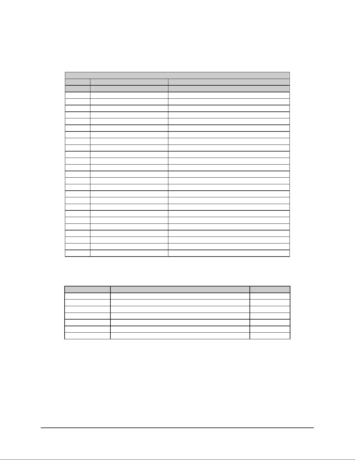
5.3.4 Tributary Data Interface Connectors (J5 and J6)
For all interface types, the 8-channel demultiplexer adds two DB-25 connectors
(J5 and J6) for tributary outputs.
Table 5-6. Tributary Data Interface Connector (J5)
Rear Panel 25-Pin D Connector
J5 DEMUX T1-4
Pin # Circuit Description
1 RD422A_1 RS-422, RX DATA (-), TRIB1
14 RD422B_1 RS-422, RX DATB (+), TRIB1
2 RC422A_1 RS-422, RX CLKA (-), TRIB1
15 RC422B_1 RS-422, RX CLKB (+), TRIB1
3 RD232_1 RS-232, RECEIVE DATA, TRIB1
16 RC232_1 RS-232, RECEIVE CLOCK, TRIB1
4 RD422A_2 RS-422, RX DATA (-), TRIB2
17 RD422B_2 RS-422, RX DATB (+), TRIB2
5 RC422A_2 RS-422, RX CLKA (-), TRIB2
18 RC422B_2 RS-422, RX CLKB (+), TRIB2
6 RD232_2 RS-232, RECEIVE DATA, TRIB2
19 RC232_2 RS-232, RECEIVE CLOCK, TRIB2
7 RD422A_3 RS-422, RX DATA (-), TRIB3
20 RD422B_3 RS-422, RX DATB (+), TRIB3
8 RC422A_3 RS-422, RX CLKA (-) ,TRIB3
21 RC422B_3 RS-422, RX CLKB (+), TRIB3
9 RD232_3 RS-232, RECEIVE DATA, TRIB3
22 RC232_3 RS-232, RECEIVE CLOCK, TRIB3
10 RD422A_4 RS-422, RX DATA (-), TRIB4
23 RD422B_4 RS-422, RX DATB (+), TRIB4
11 RC422A_4 RS-422, RX CLKA (-), TRIB4
24 RC422B_4 RS-422 ,RX CLKB (+), TRIB4
12 RD232_4 RS-232 ,RECEIVE DATA, TRIB4
25 RC232_4 RS-232, RECEIVE CLOCK, TRIB4
13 GND GROUND
5-11
Page 46
SDR-54A Satellite Demodulator Revision 4
DEMUX Option MN/SDR54A.IOM
Table 5-7. Tributary Data Interface Connector (J6)
Rear Panel 25-Pin D Connector
J6 DEMUX T5-8
Pin # Circuit Description
1 RD422A_5 RS-422, RX DATA (-), TRIB5
14 RD422B_5 RS-422, RX DATB (+), TRIB5
2 RC422A_5 RS-422, RX CLKA (-), TRIB5
15 RC422B_5 RS-422, RX CLKB (+), TRIB5
3 RD232_5 RS-232, RECEIVE DATA, TRIB5
16 RC232_5 RS-232, RECEIVE CLOCK, TRIB5
4 RD422A_6 RS-422, RX DATA (-), TRIB6
17 RD422B_6 RS-422, RX DATB (+), TRIB6
5 RC422A_6 RS-422, RX CLKA (-), TRIB6
18 RC422B_6 RS-422, RX CLKB (+), TRIB6
6 RD232_6 RS-232, RECEIVE DATA, TRIB6
19 RC232_6 RS-232, RECEIVE CLOCK, TRIB6
7 RD422A_7 RS-422, RX DATA (-), TRIB7
20 RD422B_7 RS-422, RX DATB (+), TRIB7
8 RC422A_7 RS-422 ,RX CLKA (-), TRIB7
21 RC422B_7 RS-422, RX CLKB (+), TRIB7
9 RD232_7 RS-232, RECEIVE DATA, TRIB7
22 RC232_7 RS-232, RECEIVE CLOCK, TRIB7
10 RD422A_8 RS-422, RX DATA (-), TRIB8
23 RD422B_8 RS-422, RX DATB (+), TRIB8
11 RC422A_8 RS-422, RX CLKA (-), TRIB8
24 RC422B_8 RS-422, RX CLKB (+), TRIB8
12 RD232_8 RS-232, RECEIVE DATA, TRIB8
25 RC232_8 RS-232, RECEIVE CLOCK, TRIB8
13 GND GROUND
Table 5-8. Aggregate Data and Clock
Pin # Signal Function Name
3 Receive data inverting output (RS-422) RXDa
4 Receive data non-inverting output (RS-422) RXDb
7 Ground GND
8 Carrier detect inverting CDa
17 Receive clock inverting output (RS-422) RXCa
18 Receive clock non-inverting output (RS-422) RXCb
20 Carrier detect non-inverting output (RS-422) CDb
5-12
Page 47

Chapter 6. Reed-Solomon Option
6.1 Introduction
The Reed-Solomon (AS/6285) assembly is a 1.2 x 4.2 inch (3.04 x 10.7 cm) daughter card
for the SDR-54A. Refer to Figure 6-1.
Figure 6-1. Reed-Solomon Card
6–1
Page 48

SDR-54A Satellite Demodulator Revision 4
Reed-Solomon Option MN/SDR54A.IOM
Design guidelines are in accordance with IESS-308/309 (refer to Table 6-1).
Options for the Rx required Reed-Solomon PCB contain the following
• Self-synchronizing Descrambler
• Variable Deinterleaver Depth (8 or 16)
6.2 Descrambler
The descrambler used in the Reed-Solomon assembly is a 220-1 descrambler. It has an
adverse state detector, reset by XOR’ ing bits 11 and 19. The adverse state detector counts
from 0 to 31. At count 31, it inserts a one into the descrambler. The tap points into the
descrambler are 0 and 17. The data is inverted before it is sent through the descrambler.
Refer to Figure 6-2, which shows a block diagram of the V.35 Self-Synchronizing
Descrambler.
Figure 6-2. V.35 Self-Synchronizing Descrambler
6–2
Page 49

SDR-54A Satellite Demodulator Revision 4
Reed-Solomon Option MN/SDR54A.IOM
6.3 Deinterleaver
The unique words inserted by the encoder are used by the decoder to detect the frame
boundary for synchronization of the descrambler and the deinterleaver. The deinterleaver
operates in a similar manner as the interleaver, except that it writes scrambled and R-S
encoded data (with checkbytes) into a static ram in column format, and reads in row
format. The result is data in the original RS code word format. See Figure 6-3 for the R-S
Code Word after deinterleaving.
'RSWORD'
nBYTES
2+t
CHECK BYTES
1RSPAGE
'RSWORD'
kBYTES
OF DATA
RS SYNCH
PERIOD
UNIQUE WORD BYTES
GO INTO THESE BYTE S
Figure 6-3. R-S Code Word Format
6–3
Page 50

SDR-54A Satellite Demodulator Revision 4
Reed-Solomon Option MN/SDR54A.IOM
6.4 Reed-Solomon Codec
The design implements R-S decoding by utilizing the Advanced Hardware P/N
AHA4011B chip set. Refer to Table 6-1 for R-S codes.
Table 6-1. R-S Codes
Service Data Rate
(kbit/s)
Closed Network 4.8 to 4375 kbps 225, 205, 10
Note: Reed-Solomon concatenated decoding is compatible with the Comtech EF Data
SDM-300 Series or SDM-8000 modems.
6.5 Reed-Solomon Installation
Install the Reed-Solomon card as follows:
1. Remove the six 6-32 pan head screws which secure the cover to the chassis.
Note: The cover and chassis are held together by flange tabs located on the top
and bottom surfaces.
2. Remove the cover from the chassis as follows:
a. Two extraction slots near the front of the unit are located on the top surface.
b. Separate the chassis and cover by placing a screw driver into the extraction
slots and twisting.
Note: To remove the chassis from the cover, gently pry the chassis and cover
away from each other.
Use Electrostatic Discharge (ESD) precautionary procedures when
touching, removing, or inserting PCBs.
CAUTION
3. Gently insert the Reed-Solomon card into the socket, with the card-edge (the side
with the silver strips and ‘RX Reed-Solomon’) facing downward.
4. Carefully apply a slight amount of pressure downward on the top of the card, until
it snaps into position in the connector socket’s retaining clips.
Note: The correct position of a properly installed AS/6285 Reed-Solomon card is
standing nearly upright, tilting at a slight angle, as shown in Figure 6-4.
R-S Code
(n, k, t)
6–4
Page 51

SDR-54A Satellite Demodulator Revision 4
Reed-Solomon Option MN/SDR54A.IOM
Do not overtighten the securing screws. Damage to the top chassis can
occur.
CAUTION
5. Position the top chassis in place ensuring the tabs are aligned. Press the top chassis
into the bottom while ensuring the LED light tubes and push-button switches are
aligned. Secure the top chassis with the six screws, using a driver.
Figure 6-4. Installation of Reed-Solomon Card (AS/6285)
6–5
Page 52

SDR-54A Satellite Demodulator Revision 4
Reed-Solomon Option MN/SDR54A.IOM
6.6 Functionality
6.6.1 Correlator
On the Rx (decoder) side, the correlator searches for unique words from the R-S frame.
The correlator starts in hunt mode, searching for the first two bytes of the unique word.
Upon detection of the first two bytes of the unique word, the correlator searches for the
next two bytes of the unique word. When all four bytes of the unique word are found, an
up/down counter is incremented. The correlator acknowledges a locked condition when
the up/down counter reaches a maximum count of 16.
Once the counter starts counting up, a missing byte of the unique word causes the counter
to count down. The counter must count down to zero before entering the hunt mode again,
offering some compliance for noise in the system.
After a locked condition is reached, the correlator uses the known frame sync position to
synchronize the counters that generate the deinterleaver addresses, W/R selects, and the
descrambler synchronization. The correlator converts the input data stream to an 8-bit
parallel byte format for processing by the deinterleaver and R-S decoder.
6.6.2 Error Detection
The decoder provides a means to check for uncorrectable R-S blocks. The decode Xilinx
monitors the CRTN line out of the R-S decoder. CRTN is valid during the first byte of
each R-S block. CRTN is programmed such that a low indicates that the incoming R-S
block of data was correctable.
• If CRTN is high during the first byte, then the upcoming R-S block of data
exceeded the correction capability of the R-S decoder.
• If the block is uncorrectable, the data is passed through the decoder as
received, meaning no correction was performed on that block of data.
The decode Xilinx monitors the CRTN line and latches a status line on any high state.
Approximately once every second, the M&C reads the status line and reports any UAS
(unavailable seconds) as a stored fault on the modems front panel. The status line is
cleared every time the M&C reads the status.
Refer to Figure 6-5 for a block diagram of the Reed-Solomon Decoder section.
6–6
Page 53

SDR-54A Satellite Demodulator Revision 4
Reed-Solomon Option MN/SDR54A.IOM
RXSATDAT
(SERIAL)
RXSATCLK
UNIQUE WORD
DETECTOR
SERIAL
TO PARALLEL
CONVERTER
RAM
DEINTERLEAVER
DEINTERLEAVER
ADDRESS
GENERATOR
Figure 6-5. Reed-Solomon Decoder Section Block Diagram
6.7 BER Performance
Table 6-2. BER Performance Curve Data
Eb/N
0 (dB) Specification
BER 1/2 Rate 3/4 Rate 7/8 Rate
10-6 N/A 5.6 6.7
10-7 N/A 5.8 6.9
10-8 N/A 6.0 7.1
-10
10
5.0 6.3 7.5
RS CODEC
(DECODER SECTION)
RS TIMING CONTROLLER
PARALLEL
TO SERIAL
CONVERTER
SYNCHRONOUS
DESCRAMBLER
DMXDAT
(SERIAL)
DMXCLK
6–7
Page 54

SDR-54A Satellite Demodulator Revision 4
Reed-Solomon Option MN/SDR54A.IOM
Reed-Solomon
10-5
B
E
R
10-6
10-7
10-8
1/2 RATE
10-9
-10
10
3.0 4.0 5.0 6.0
3/4 RATE
7/8 RATE
7.0 8.0 9.0 10.0 11.0
Eb/N0 (dB)
Figure 6-6. BER Performance with Noise, Viterbi Decoder, and Reed-Solomon (Optional)
6.7.1 Specification
Table 6-3. Reed-Solomon Specifications
Decoder Type IESS 308 Polynomial
Deinterleaver Type IESS 308 Block (modified)
Deinterleaver Depth 8 or 16
RS Code Words 225,205,10
Descrambler Modified V.35 Self Synchronizing
6–8
Page 55

SDR-54A Satellite Demodulator Revision 4
Reed-Solomon Option MN/SDR54A.IOM
6.7.2 Interface Connector
Connector type 72-pin simm.
Table 6-4. Interface Connector
Pin # Signal Description
1 to 4, 69 to 72 GND Ground
5 to 8, 65 to 68 +5V +5V
9 to 11 Spare 0-2 NC
12 to 15 RS_SPR3-6 Spares from FPGA
16, 17 Spare 3, 4 NC
18 TXDAT NC (Pull up)
19 TXCLK NC (Pull up)
20 to 22 Spare 5-7 NC
23 SCT_OUT NC
24 Spare 8 NC
25 DEC_DAT (RS) Data to Main
26 DEC_CLK (RS) Clock from Main
27 RS_DAT RX Data from Main
28 RS_CLK RX Clock from Main
29 Spare 9 NC
30 /TRS_EN NC
31 /RS_CS RS Chip Select
32 Spare 10 NC
33 SDA IIC Port Expander Data
34 SCL IIC Port Expander Clock
35 Spare 11 NC
36 to 43 BAD[0..7] M&C Address/Data Bus
44 Spare 12 NC
45 BALE M&C Buffer ALE
46 /BRD M&C Buffer Read
47 /BWR M&C Buffer Write
48 Spare 13 NC
49 RSXLX_CLK 25 MHz Clock RS Xilinx
50 Spare 14 NC
51 AHA_CLK 25 MHz Clock RS Decoder
52 RS_SPR7 NC
53 RI_SP NC
54 RR_SP NC
55 RT_SP NC
56 RS_SPR8 NC
57 to 59 TXPA0-TXPA2 NC
60 RS_SPR9 NC
61 to 63 RXPA0-RX_PA2 ID
64 RS_SPR10 NC
6–9
Page 56

SDR-54A Satellite Demodulator Revision 4
Reed-Solomon Option MN/SDR54A.IOM
Notes:
_____________________________________________________________________________
_____________________________________________________________________________
_____________________________________________________________________________
_____________________________________________________________________________
_____________________________________________________________________________
_____________________________________________________________________________
_____________________________________________________________________________
_____________________________________________________________________________
_____________________________________________________________________________
_____________________________________________________________________________
_____________________________________________________________________________
_____________________________________________________________________________
_____________________________________________________________________________
_____________________________________________________________________________
_____________________________________________________________________________
_____________________________________________________________________________
_____________________________________________________________________________
_____________________________________________________________________________
_____________________________________________________________________________
_____________________________________________________________________________
_____________________________________________________________________________
_____________________________________________________________________________
_____________________________________________________________________________
_____________________________________________________________________________
_____________________________________________________________________________
_____________________________________________________________________________
_____________________________________________________________________________
_____________________________________________________________________________
_____________________________________________________________________________
_____________________________________________________________________________
_____________________________________________________________________________
_____________________________________________________________________________
_____________________________________________________________________________
_____________________________________________________________________________
_____________________________________________________________________________
_____________________________________________________________________________
_____________________________________________________________________________
6–10
Page 57

Chapter 7. Fully Accessible
System Topology (FAST)
This appendix describes the Fully Accessible System Topology (FAST) option available
for the demodulator.
7.1 FAST Accessible Options
Comtech EF Data’s FAST system allows immediate implementation of different options
through the user interface keypad. Some FAST options are available through the basic
platform unit, while others require that the unit is equipped with optional hardware, or
that the hardware be installed in the field.
The options available through the FAST architecture include:
Variable Data Rates
•
Other options are available through conventional changes, such as installing daughter
card PCBs. Refer to Section D.2, Conventional Options, for additional information.
7.2 FAST System Theory
FAST is an enhancement feature available only in Comtech EF Data products, enabling
on-location upgrade of the operating feature set—in the rack—without removing a
modem from the setup. When service requirements change, the operator can upgrade the
topology of the modem to meet those requirements within minutes after confirmation by
Comtech Ef Data. This accelerated upgrade can be accomplished only because of FAST’s
extensive use of programmable devices incorporating Comtech Ef Data-proprietary signal
processing techniques. These techniques allow the use of a unique access code to enable
7–1
Page 58

SDR-54A Satellite Demodulator Revision 4
Fully Accessible System Topology (FAST) MN/SDR54A.IOM
configuration of the available hardware. The access code can be purchased at any time
from Comtech Ef Data. Once obtained, the access code is loaded into the unit through the
front panel keyboard or the rear remote port.
With the exclusive FAST technology, operators have maximum flexibility for enabling
functions, as they are required. FAST allows an operator to order a modem precisely
tailored for the initial application, reducing risk and cost overruns during the application
integration process.
7.3 Implementation
FAST is factory-implemented in the modem at the time of order. Hardware options for
basic modems can be ordered and installed either at the factory or in the field. The
operator can select options that can be activated easily in the field, depending on the
current hardware configuration of the modem.
7.3.1 Activation Procedure
1. Obtain Demodulator serial number as follows:
a. Establish a connection to M&C REMOTE port.
b. [ENTER] <1/SNUM_'cr'
c. Record the following serial numbers as follows.
• Record Modem Serial Number: ______________.
• Record Card #1 Serial Number: ______________.
• Record Card #2 Serial number: _______________.
d. [ENTER] <MOI_'cr' to view available features.
Single Rate [ ] Card #1 [ ]
Low Rate Variable [ ] Card #2 [ ]
Full Rate Variable [ ]
7–2
Page 59

SDR-54A Satellite Demodulator Revision 4
Fully Accessible System Topology (FAST) MN/SDR54A.IOM
Notes:
1. If the menu displays a “0”, the unit will need to be returned to the
manuafacturer for desired hardware upgrade.
2. If the menu displays an “X”, the unit can be upgraded in the field.
3. If the unit displays a “+”, the feature is installed.
4. If the unit displays a “-”, the feature is FAST accessible.
e. Press [CLEAR].
f. [ENTER] <1/C10I_'cr' to select Card #1 (Overhead Card) options.
4-Channel [ ] 8-Channel [ ]
g. [ENTER] <1/C20I_'cr' to select CARD #2 (Reed-Solomon Card) options.
INTELSAT [ ]
h. Contact an Comtech EF Data Sales Representative to order desired features.
i. Comtech EF Data Customer personnel will verify the order and provide an
invoice and instructions.
7–3
Page 60

SDR-54A Satellite Demodulator Revision 4
Fully Accessible System Topology (FAST) MN/SDR54A.IOM
Notes:
_______________________________________________________________________
_______________________________________________________________________
_______________________________________________________________________
_______________________________________________________________________
_______________________________________________________________________
_______________________________________________________________________
_______________________________________________________________________
_______________________________________________________________________
_______________________________________________________________________
_______________________________________________________________________
_______________________________________________________________________
_______________________________________________________________________
_______________________________________________________________________
_______________________________________________________________________
_______________________________________________________________________
_______________________________________________________________________
_______________________________________________________________________
_______________________________________________________________________
_______________________________________________________________________
_______________________________________________________________________
_______________________________________________________________________
_______________________________________________________________________
_______________________________________________________________________
_______________________________________________________________________
_______________________________________________________________________
_______________________________________________________________________
_______________________________________________________________________
_______________________________________________________________________
_______________________________________________________________________
_______________________________________________________________________
_______________________________________________________________________
_______________________________________________________________________
_______________________________________________________________________
_______________________________________________________________________
_______________________________________________________________________
_______________________________________________________________________
_______________________________________________________________________
_______________________________________________________________________
_______________________________________________________________________
_______________________________________________________________________
7–4
Page 61
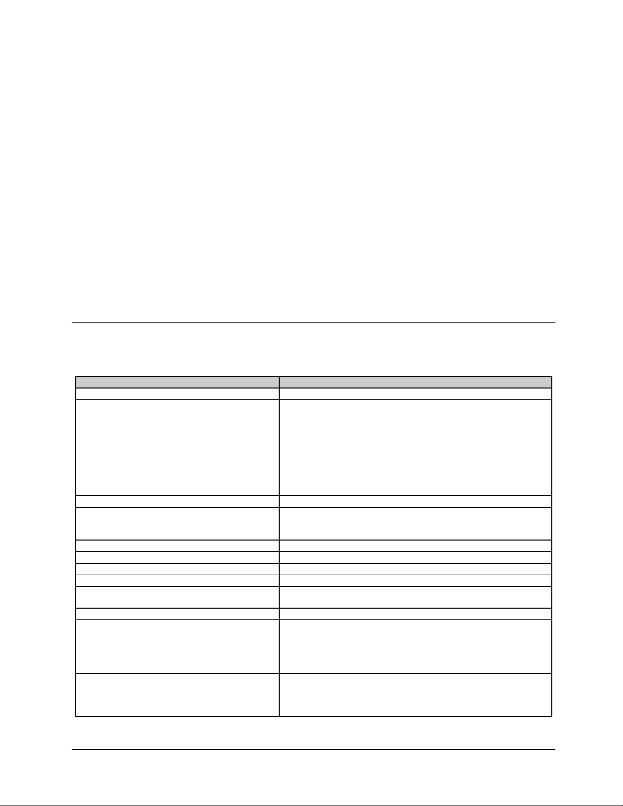
Chapter 8. Specifications
8.1 Specifications
Table 8-1. Demodulator Specifications
Parameter Specification
RF Input Frequency Range 950.0 to 1550.0 MHz, in graduated 10 kHz steps
RF Input Level:
Typical
Guaranteed
RF Input Impedance
RF Input Return Loss (950.0 to 1550.0 MHz):
Typical
Guaranteed
RF Input Connector F type (female)
LNB Power
Baseband Filtering 4-Pole Butterworth, EFData Closed, Intelsat open
Demodulation Coherent QPSK and BPSK (selectable)
Acquisition Range 10 kHz to 1 MHz, programmable in 10 kHz increments, range is
Symbol Rate Range (variable) 9.6 to 2500.0 kbps
Data Rate Change (variable):
QPSK
BPSK
Forward Error Correction Viterbi K = 7 decoder, 1/2 rate, 3/4 rate, and 7/8 rate
-90 to -30 dBm
-80 to -30 dBm
Notes:
For symbol rates < 64 kbps, input is –40 dBm max.
For symbol rates > 2048 ks/s, input level is –75 dBm min.
For all other symbols rates, the typical absolute input is
–90 dBm min.
75Ω with a retun loss of ≥ 8 dB return loss
>10 dB
> 8 dB
+24 ± 1 VDC (500 mA maximum)
rounded to nearest multiple of the operating symbol rate.
9.6 to 4000.0 kbps, in 1.0 bps steps
4.8 to 1250.0 kbps, in 1.0 bps steps
Note: For RS-232 interface, maximum data rate = 64 kbps.
Optional: Reed-Solomon IESS308/309 Concatenated 225, 205
T=10
8–1
Page 62

SDR-54A Satellite Demodulator Revision 4
Specifications MN/SDR54A.IOM
Table 8-1. Specifications (Continued)
Parameter Specification
Bit Error Rate:
Viterbi 1/2 rate:
Typical
Guaranteed
Viterbi 1/2 Rate with Reed-
Solomon
Ambiguity Resolution Method Differential decoder
Descrambling CCITT V.35 INTELSAT modified.
Deinterleaver (RS Codec) Depth 8
Differential Decoder Selectable On or Off
Composite Input Power, maximum Composite Input Power is –8.
Data Interface:
Connector Type
Clock Jitter 2.0 dB maximum jitter gain, 4% RMS of 1/symbol rate absolute.
Status LEDs Power, carrier lock, fault, and LNB power
Certification The demodulator shall be both CE mark and FCC certified. CE
-8
1 x 10
for Eb/N0 6.7 dB
1 x 10⁻⁸ for Eb/N0 7.2 dB
-10
1 x 10
Modified V.35 Self-Synchronizing (Closed Network RS option).
None.
Depth 16
Note: Hardware designed to attempt to support variable depth.
Synchronous RS-232 and RS-422 (selectable)
25-pin sub-D (female) rack mount, desktop
mark testing will be done for Conducted and Radiated Emissions
per EN55022. Radiated immunity will be tested per EN50082-1.
Low voltage directive safety will be tested per EN60950. The unit
will be tested per FCC Part 15 Class B.
for Eb/N0 5.0 dB
Note: Warm up periods are required for the folowing operating temperature:
0 to 60°C 15 minutes, approximately
0°C 45 minutes, approximately
Table 8-2. Environmental and Physical Specifications
Parameter Specification
Environmental:
Operating Temperature:
Desktop
Rack Mount
Temperature (Storage)
Humidity (non-condensing)
Frequency Stability:
Standard
High-Stability
Dimensions:
Desktop
Rack Mount (1RU)
Unit-to-Unit Delay Variation
0° to +50°C (+32° to +122°F)
-20° to +60°C (-4° to +140°F)
-40° to +70°C (-40° to +158°F)
0 to 95% at 40°C (40°F)
±15 ppm
± 0.5 ppm
17.36W x 2.04H x 8.35D in. (44.1W x 5.2H x 21.2D cm)
19W x 1.75H x 8.35D in. (48.3W x 4.4H x 21.2D cm)
< 2.3% of 1 (data rate) for R 1/2 only, without Reed-Solomon
concatenated decoder.
< 1µs for symbol rates 19.2 to 800 ks/s
< 1µs for symbol rates < 19.2 ks/s
8–2
Page 63

SDR-54A Satellite Demodulator Revision 4
Specifications MN/SDR54A.IOM
8.1.1 Prime Power Interface
The demodulator will not exceed a total power consumption of 40W. The demodulator
card receives the following prime power supplies:
+5V Supply
+12V Supply
-12V Supply
For rack mount and desktop configurations, the power consumption shall not exceed 40W.
The input will be as follows:
AC 90 to 132 VAC or 175 to 264 VAC,
47 to 63 Hz
DC (Option)
48 or 24 VDC, ± 5% at TBDA
8.1.2 Desired Carrier Input Power
For symbol rates > 2048 ks/s, the desired carrier input power is –75 to –30 dBm
guaranteed.
• For symbol rates from 64 to 2048 ks/s, the desired carrier input power is –80
to –30 dBm guaranteed.
• For symbol rates < 64 ks/s, the desired inpout power is –80 to –40 dBm
guaranteed.
• For all symbol rates, the typical absolute minimum input is –90 dBm.
+5 VDC, ± 5% at 2.0A
+12 VDC, ± 5% at 1.2A
-12 VDC, ± 5% at 0.5A
IEC Connector
3-position Terminal
block
8.1.3 Composite to Desired Input Power
The composite to desired ratio is 47 dB with a carrier of 9.6 ks/s wide (-55 dBm maximum
input) and 24 dB with a carrier of 2500 ks/s wide (-32 dBm maximum input).
8.1.4 IF Input Shape
The basic spectral mask is equivalent to a 4-pole Butterworth, and is compatible with the
SDM-51, -52 products. The demodulator is designed such that other spectral shaping is
accommodated with firmware upgrades.
Examples are IESS Open Network and Comtech EF Data Closed Network filtering.
Up to four different filter types are programmed/selected via the M&C interface.
8–3
Page 64

SDR-54A Satellite Demodulator Revision 4
Specifications MN/SDR54A.IOM
8.1.5 Adjacent Channel Interface Performance
The degradation in performance in terms of Eb/No shall not exceed 0.5 dB as a result of
adjacent channel interference caused by the presence of two simultaneous adjacent
channels. The channels are similar to the desired but up to 6 dBc higher in power. The
channel spacing varies as follows:
QPSK
BPSK
± 1.3 x symbol clock
± 1.3 x symbol clock
8.1.6 Frequency Stability
The frequency stability of the standard configuration is ± 15 ppm. The high-stability
option provides for a frequency stability of ± 0.5 ppm.
8.2 Digital Data Rates
The data rate (Table 8-3) for the demodulator is programmable in 1 bps steps. The symbol
rate is automatically calculated based on demodulation type and FEC coding. Any data
rate entered that exceeds data rate or symbol rate specifications will be rejected. The
demodulator is capable of supporting symbol rates from 9.6 kbps to 2.5 Ms/s. This
corresponds to data rates as follows:
Table 8-3. Digital Data Rates
Modulation FEC Data Rate
BPSK 1/2 Viterbi 4.8 to 1250 kbps
QPSK 1/2 Viterbi 9.6 to 2500 kbps
QPSK 3/4 Viterbi 14.4 to 3750 kbps
QPSK 7/8 Viterbi 16.8 to 4000 kbps
BPSK 1/2 Viterbi & Reed-Solomon 4.8 to 1138 kbps
QPSK 1/2 Viterbi & Reed-Solomon 9.6 to 2277 kbps
QPSK 3/4 Viterbi & Reed-Solomon 14.4 to 3416 kbps
QPSK 7/8 Viterbi & Reed-Solomon 16.8 to 3986 kbps
Note: For RS-232 data interface, maximum data rate = 64.0 kbps.
8–4
Page 65

SDR-54A Satellite Demodulator Revision 4
Specifications MN/SDR54A.IOM
8.2.1 Demodulation and FEC Decoding Types
The following combinations (Table 8-4) of demodulation and forward error correction
decoding are available:
Table 8-4. Demodulation and FEC Decoding Types
Decoder Code Rate Demodulation
Viterbi, K7 1/2 BPSK
Viterbi, K7
Reed-Solomon
Viterbi, K7 1/2, 3/4, 7/8 QPSK
Viterbi, K7
Reed-Solomon
1/2
225/205
1/2, 3/4, 7/8
225/205
BPSK
QPSK
Note: Hardware designed to attempt to support programmable R-S Code words.
8.2.2 BPSK and QPSK BER Performance with Noise
BER performance for the receiver for QPSK and BPSK modulation types is shown in
Table 8-5 and Figure 8-1.
Table 8-5. BPSK and QPSK BER Performance
BER 1/2 Rate 3/4 Rate 7/8 Rate
10-3 N/A 5.2 6.4
10-4 4.8 6.0 7.2
10-5 5.5 6.7 7.9
10-6 6.1 7.5 8.6
10-7 6.7 8.2 9.2
10-8 7.2 8.8 9.9
Eb/N0 (dB) Specification
8.2.3 QPSK and BPSK Performance with Noise and Reed-Solomon
BER performance for the receiver for QPSK and BPSK modulation type with ReedSolomon is shown in Table 8-6).
Table 8-6. QPSK and BPSK BER Performance with Reed-Solomon
BER 1/2 Rate 3/4 Rate 7/8 Rate
10-6 N/A 5.6 6.7
10-7 N/A 5.8 6.9
10-8 N/A 6.0 7.1
-10
10
5.0 6.3 7.5
Eb/N0 (dB) Specification
8–5
Page 66

SDR-54A Satellite Demodulator Revision 4
Specifications MN/SDR54A.IOM
-2
10
SPECIFICATIONS
B
E
R
10
10
10
10
10
-3
-4
-5
-6
-7
1/2 RATE
3/4 RATE
7/8 RATE
-8
10
3.0 4.0 5.0 6.0
Figure 8-1. BPSK and QPSK BER Performance
7.0 8.0 9.0 10.0 11.0
Eb/N0 (dB)
8–6
Page 67

SDR-54A Satellite Demodulator Revision 4
Specifications MN/SDR54A.IOM
8.3 Carrier and Clock Acquisition Time
Table 8-7. Carrier and Clock Acquisition Time
Viterbi
Symbol Rate Range BPSK Time QPSK Time
< 2500K
512K ≤
178K ≤
70K ≤
40K ≤
19.2K ≤
R
R
s
< 512K
R
s
< 178
R
s
< 70K
R
s
< 40K
R
s
< 19.2K < 110 sec < 220 sec
s
The receiver will acquire carrier and data clock synchronization from continuous
transmissions only from a randomly modulated portion of the received transmission
(i.e., without preamble) with a probability of success of greater than 95% per Table 8-7.
The above probability of success is met under the following worst case conditions:
• The input Eb/N0 is no less than 6.0 dB for 1/2 rate coding, 7.4 dB for 3/4 rate, and
8.5 dB for 7/8 rate.
• Carrier frequency uncertainty of ± 30 kHz.
• Data clock frequency error of ± 100 PPM.
≤ 2.55 sec ≤ 2.55 sec
≤ 20.0 sec ≤ 10.0 sec
≤ 5 sec ≤ 10 sec
≤ 25 sec ≤ 50 sec
≤ 55 sec ≤ 1100 sec
8.3.1 Received IF Carrier Acquisition Range
The acquisition range of the demodulator is programmed from 10.0 kHz to 1 MHz,
in steps of 10 kHz.
8.3.2 Received Data Clock Frequency Error
The data clock frequency error of the signal applied to the demodulator input must not
exceed ± 100 PPM.
8–7
Page 68

SDR-54A Satellite Demodulator Revision 4
Specifications MN/SDR54A.IOM
8.4 Signal Level Indication for Antenna Pointing
The receiver provides the AGC control signal as an output to aid the user in coarse
pointing the antenna towards the satellite. The AGC control signal is provided both as an
analog signal, and as a digital value through the M&C interface (per the M&C interface
specification). The analog signal is a buffered DC output, proportional to the receive
signal level, available on the front panel M&C connector at 10 mA maximum, 0 to 5V.
For fine antenna pointing, the estimated Eb/N0 value will be used. The Eb/N0 value is
available to the host computer or terminal via the M&C interface.
8.5 Unit-to-Unit Delay Variation
The demodulator will have a unit-to-unit delay variation for rate 1/2 only, as follows
without Reed-Solomon.
Symbol Rate Range Delay Variation
19.2k ≤ RS ≤ 800K
RS < 19.2K
1 µS
2 µS
8–8
Page 69

SDR-54A Satellite Demodulator Revision 4
Specifications MN/SDR54A.IOM
8.6 Monitor and Control (M&C) Specification
Refer to (Table 8-8) for M&C specifications.
Table 8-8. Monitor and Control Specifications
Parameter Specification
Interface Asynchronous RS-232
Connector Type 9-pin sub-D (female)
Baud Rate 9600 bps
Data Format 11 bits/characters: 7 data, 2 stop, 1 start, and 1 parity
Parity Even
Configuration Parameters:
BER Threshold
Code Rate (1/2, 3/4, or 7/8)
Data Rate
Data Inhibit
Demodulation Type
Demux Tributary Clock Phase Demux
Tributary Data Rate
Demux Tributary Data Phase
Demux Tributary Interface Type
Demux Tributary Output Mapping
Descrambler Decoder
Differential Decoder
L-Band Frequency
LNB Power Mon:
Reacquisition Time
Reed-Solomon Decoder
Reed-Solomon Deinterleaver Depth
SLRC Group Address
SLRC Individual Address
Spectral Rotation
Sweep Range
Sweep Reset
Non-volatile Configuration Storage Configuration retained without prime power for at least
Fault Status BER Threshold
Monitor Status Corrected BER
System Status DSP Firmware/ASIC Configuration Data
1E-3 to 1E-8 or None
QPSK or BPSK (1/2, 3/4, and 7/8)
4.8 to 4375 kbps
ON/OFF
INTELSAT Open, CEFD Closed, SDM-51
INV/NRM
600 bps to 4 Mbps
INV/NRM
RS-232 or RS-422
1 to 8
Enable
Enable
950.0 to 1550.0 MHz
Low Limit: 0 to 500 mA/High Limit: 0 to 500 mA
0 to 99 seconds
ON/OFF
8 or 16
0 to 255
0 to 65535
INV/NRM
10.0 to 1000 kHz
Stop Sweep
1 year
Carrier Detect
Demux Module/Lock
DSP Active
FPGA Program
LNB Power
Reed-Solomon Module/Lock
RF LO Lock Detect
E
b/N0
Raw BER
Receive Frequency Offset
Receive Signal Level
Equipment Type
FPGA Firmware
M&C Firmware
8–9
Page 70

SDR-54A Satellite Demodulator Revision 4
Specifications MN/SDR54A.IOM
8.6.1 M&C Interface Connector(s)
The M&C interface is an Asynchronous, RS-232 interface on a 9-pin female D-sub
connector.
The connector is located on both the front and back of the rackmount
configuration and on the back of the desktop configuration. The connectors in the
rackmount and desktop configurations are wired in parallel.
either port, but the user must verify that commands will not be issued simultaneously.
Commands can be issued from
Status messages will be sent to both ports simultaneously.
8.6.2 M&C Interface Configuration
The M&C interface is configured for 9600 baud, 7 data bits, 1 parity bit (even), and 2 stop
bits.
8.6.3 M&C Communications
Commands and data are transferred on the M&C communications link as
US ASCII-encoded character strings.
The M&C communications link is operated in a half-duplex mode.
Communications on the remote link are initiated by a remote controller or terminal.
receiver never transmits data on the link unless it is commanded to do so.
8.6.4 M&C Message Formats
The message formats for the M&C interface are described in the SDR-54A Installation and
Operation Manual (draft available).
8.7 Monitored Signals
The operator can read one of the following, continually updated, performance monitors:
• Receive signal level
• Raw BER
• Corrected BER
b/N0
• E
• Receive frequency offset
The
8–10
Page 71

SDR-54A Satellite Demodulator Revision 4
Specifications MN/SDR54A.IOM
8.8 Faults Monitored
The faults monitored by the M&C and the resulting action taken are as follows:
FPGA Program FAULT LED TTL-OC FORM-C
DSP Active FAULT LED TTL-OC FORM-C
RF LO Lock Detect FAULT LED TTL-OC FORM-C
BER Threshold FAULT LED TTL-OC FORM-C
Carrier Detect LOCK LED
LNA Power FAULT LED TTL-OC FORM-C
LNB-POWER LED
DMX Module/Lock FAULT LED TTL-OC FORM-C
RS Module/Lock FAULT LED TTL-OC FORM-C
The operator can also read the fault status via the M&C interface.
The TTL open collector fault signal and the Form-C contact closure signals are available
on the Fault connector.
An optional LNB power current monitor is available.
8.9 Fault Status
The operator can read the following Fault Status information via the M&C interface:
SLRC Address (group or local) Remark
Carrier Detect OK/FLT
BER Threshold OK/FLT
RF SYNC Lock Detect OK/FLT
FPGA Load OK/FLT
DSP Comm OK/FLT
LNB Power OK/FLT/OFF
DEMUX OK/FLT/OFF
Reed-Solomon OK/FLT
8–11
Page 72

SDR-54A Satellite Demodulator Revision 4
Specifications MN/SDR54A.IOM
8.10 Space Link Remote Control (SLRC) Specifications
The Space Link Remote Control operation is described in Comtech EF Data specification
SP/5487.
controlled via SLRC:
BER Threshold 3 to 8 or FF (Off)
Code Rate QPSK or BPSK 1/2, 3/4, and 7/8
Data Rate 4.8 to 4375 kbps
Data Inhibit On or Off
Demodulation Type INTL Open, CEFD Closed, or SDM-51
DEMIUX TRIB x Clock Phase INV or NRM
DEMIUX TRIB x Data Rate 0.6 to 4000 kbps or Off
DEMIUX TRIB x Data Phase INV or NRM
DEMIUX TRIB x Interface Type RS-232/RS-422
DEMIUX TRIB x Output Map 1 to 8
Fail-Safe Coonfirmation Carrier Lock or Time-Out
Fail-Safe Confirmation Time-Out 0 to 65535 seconds
LNB Power Mon. Low-Limit 0 to 500 mA
LNB Power Mon. High Limit 0 to 500 mA
RF Input Frequency 950.0 to 1550.0 MHz
Reed-Solomon Decoder On/Off
Reed-Solomon Deinterleaver Depth 8 or 16
Sweep Range 1.0 to 1000 kHz
Sweep Reacquisition 0 to 99 seconds
Spectral Rotation INV or NRM
Note:
The following is a summary of demodulator configuration parameters that can be
Parameter Specification
Requires use of Comtech EF Data modulator and PC software.
8–12
Page 73

SDR-54A Satellite Demodulator Revision 4
Specifications MN/SDR54A.IOM
8.11 Integrated Demultiplexer Option
8.11.1 2/4 Channel Demux (SP/5231) (Sosoft)
Demultiplexer Type Synchronous, symmetrical data rates on all
tributaries
Number of Tributary Channels 2 or 4, automatic detection
Tributary Data Interface RS-422 or RS-232, 25-pin D-sub
Tributary Data Rate: SP/5231
4-Channel Mode
2-Channel Mode
Clock
Synchronization Indicator TTL, on interface connector (1 = SYNC)
Mode Indicator TTL, on interface connector (0 = 2 channel mode)
9.6 to 64.0 kbps, 32/129 of aggregate channel
9.6 to 128.0 kbps, 64/129 of aggregate channel
50% duty cycle ± 10%, phase locked to aggregate
channel
8.11.1.1 Tributary Data Output Connector (J4)
Connector type: Dual row (2 x 13), Female.
Tributary Data Output Connector
Signal Function Name Pin #
Trib #1 Data inverting output (RS-422) RXDaT1 1
Trib #1 Data non-inverting output (RS-422) RXDbT1 2
Trib #1 Clock inverting output (RS-422) RXCaT1 3
Trib #1 Clock non-inverting output (RS-422) RXCbT1 4
Trib #2 Data inverting output (RS-422) RXDaT2 11
Trib #2 Data non-inverting output (RS-422) RXDbT2 12
Trib #2 Clock inverting output (RS-422) RXCaT2 16
Trib #2 Clock non-inverting output (RS-422) RXCbT2 17
Trib #3 Data inverting output (RS-422) RXDaT3 18
Trib #3 Data non-inverting output (RS-422) RXDbT3 19
Trib #3 Clock inverting output (RS-422) RXCaT3 20
Trib #3 Clock non-inverting output (RS-422) RXCbT3 21
Trib #4 Data inverting output (RS-422) RXDaT4 22
Trib #4 Data non-inverting output (RS-422) RXDbT4 23
Trib #4 Clock inverting output (RS-422) RXCaT4 24
Trib #4 Clock non-inverting output (RS-422) RXCbT4 25
Demux synchronization indicator (TTL, 1 = SYNC) DMXSYNC 6
Demux mode indicator (TTL, 0 = 2 channel mode) DMXMD 9
Ground GND 13, 26
No Connects 5, 7, 8, 10, 14, 15
8–13
Page 74

SDR-54A Satellite Demodulator Revision 4
Specifications MN/SDR54A.IOM
8.11.1.2 Aggregate Data/Clock Input and Power Connector (J3)
Connector type: Dual row (2 x 5), Female.
Table 8-9. Aggregate Data/Clock Input and Power Connector (J3)
Aggregate Data Input and Power Connector
Signal Function Name Pin #
Aggregate data input (inverted TTL) /ADAT 1
Aggregate clock input (TTL) ACLK 7
+5V power VCC 9
Ground GND 10
No connects 2, 3, 4, 5, 6, 8
8.12 8-Channel Demux (SP/5839) (Comtech EFData)
8.12.1 Specifications
Table 8-10. 8-Channel Demux Specifications
Aggregate Input:
Type Synchronous (clock/data).
Data/Clock Interface TTL (inverted data). Data valid on rising edge of clock.
Data Rate 4001.3 kbps maximum, the aggregate data rate is the sum of all
tributary data rates plus the multiplex overhead.
Clock
Multiplex Technique Data interleaved time division.
Overhead 1.3 kbps fixed per frame.
Tributary Outputs:
Number of Channels One to eight.
Data Rate 600 bits/second to 4000.0 kbps/second (configurable for each
Type Synchronous clock and data.
Data Interface RS-422 or RS-232.
Clock
Lock Time 1 second maximum after demodulator Carrier Detect (CD).
Operational Bit Error Rate
Performance
Input Power
Environmental:
Operating Temperature
Storage Temperature
Humidity Up to 95% non-condensing.
50% duty cycle, ± 10%.
tributary in 100 bits/second increments).
Notes:
1. RS-232 maximum data rate is 64.0 kbps.
2. The sum of all tributary data rates plus overhead cannot
exceed the maximum aggregate data rate of
4001.3 kbps/second.
50% duty cycle, ± 10%, phase locked to aggregate clock input,
0.25 dB maximum jitter gain from aggregate clock input.
Will lock and maintain synchronization with BER ≥ 10
5 VDC, ±
-20° to +60°C.
-55° to +125°C.
10%, 900 mA maximum.
-3
.
8–14
Page 75

SDR-54A Satellite Demodulator Revision 4
Specifications MN/SDR54A.IOM
Table 8-10. 8-Channel Demux Specifications (Continued)
Interface Connectors:
JP1 +5 VDC power, aggregate data, I2C communications to
demodulator card.
JP2 Output sync and mode signals.
JP3 26-pin header, for tributary interfaces 1 through 4.
JP4 26-pin header, for tributary interfaces 5 through 8.
Unit-to-Unit Delay Variation < 10% of 1/tributary data rate for identically configured
demultiplexers. (See Note.)
Breakout Panel (UB-54) Optional 1 RU breakout panel converts interface to eight separate
15-pin ‘D” tributary interfaces.
Note: This is in addition to the delay variation of the base unit.
8.12.2 Tributary Data Connector (J3)
Table 8-11. Tributary Data Connector (J3)
JP3
Pin #
1 RD422A_1 RS-422, RX DATA (-), TRIB1
2 RD422B_1 RS-422, RX DATB (+), TRIB1
3 RC422A_1 RS-422, RX CLKA (-), TRIB1
4 RC422B_1 RS-422, RX CLKB (+), TRIB1
5 RD232_1 RS-232, RECEIVE DATA, TRIB1
6 RC232_1 RS-232, RECEIVE CLOCK, TRIB1
7 RD422A_2 RS-422, RX DATA (-), TRIB2
8 RD422B_2 RS-422, RX DATB (+), TRIB2
9 RC422A_2 RS-422, RX CLKA (-), TRIB2
10 RC422B_2 RS-422, RX CLKB (+), TRIB2
11 RD232_2 RS-232, RECEIVE DATA, TRIB2
12 RC232_2 RS-232, RECEIVE CLOCK, TRIB2
13 RD422A_3 RS-422, RX DATA (-), TRIB3
14 RD422B_3 RS-422, RX DATB (+), TRIB3
15 RC422A_3 RS-422, RX CLKA (-), TRIB3
16 RC422B_3 RS-422, RX CLKB (+), TRIB3
17 RD232_3 RS-232, RECEIVE DATA, TRIB3
18 RC232_3 RS-232, RECEIVE CLOCK, TRIB3
19 RD422A_4 RS-422, RX DATA (-), TRIB4
20 RD422B_4 RS-422, RX DATB (+), TRIB4
21 RC422A_4 RS-422, RX CLKA (-), TRIB4
22 RC422B_4 RS-422, RX CLKB (+), TRIB4
23 RD232_4 RS-232, RECEIVE DATA, TRIB4
24 RC232_4 RS-232, RECEIVE CLOCK, TRIB4
25 GND GROUND
26 GND GROUND
Demux T1-4
Circuit
Description
8–15
Page 76

SDR-54A Satellite Demodulator Revision 4
Specifications MN/SDR54A.IOM
8.12.3 Tributary Data Connector (J4)
Table 8-12. Tributary Data Connector (J4)
JP4
Pin #
1 RD422A_5 RS-422, RX DATA (-), TRIB5
2 RD422B_5 RS-422, RX DATB (+), TRIB5
3 RC422A_5 RS-422, RX CLKA (-), TRIB5
4 RC422B_5 RS-422, RX CLKB (+), TRIB5
5 RD232_5 RS-232, RECEIVE DATA, TRIB5
6 RC232_5 RS-232, RECEIVE CLOCK, TRIB5
7 RD422A_6 RS-422, RX DATA (-), TRIB6
8 RD422B_6 RS-422, RX DATB (+), TRIB6
9 RC422A_6 RS-422, RX CLKA (-), TRIB6
10 RC422B_6 RS-422, RX CLKB (+), TRIB6
11 RD232_6 RS-232, RECEIVE DATA ,TRIB6
12 RC232_6 RS-232, RECEIVE CLOCK, TRIB6
13 RD422A_7 RS-422, RX DATA (-), TRIB7
14 RD422B_7 RS-422, RX DATB (+), TRIB7
15 RC422A_7 RS-422, RX CLKA (-), TRIB7
16 RC422B_7 RS-422, RX CLKB (+), TRIB7
17 RD232_7 RS-232, RECEIVE DATA, TRIB7
18 RC232_7 RS-232, RECEIVE CLOCK, TRIB7
19 RD422A_8 RS-422, RX DATA (-), TRIB8
20 RD422B_8 RS-422, RX DATB (+), TRIB8
21 RC422A_8 RS-422, RX CLKA (-), TRIB8
22 RC422B_8 RS-422, RX CLKB (+), TRIB8
23 RD232_8 RS-232, RECEIVE DATA, TRIB8
24 RC232_8 RS-232, RECEIVE CLOCK, TRIB8
25 GND GROUND
26 GND GROUND
Demux T5-8
Circuit
Description
Note: Tributary data connectors are on Demux Board (PL5839).
8–16
Page 77

SDR-54A Satellite Demodulator Revision 4
Specifications MN/SDR54A.IOM
8.12.4 Aggregate Data/Clock Input, Power Connector
Connector type: Dual row (2 x 5), Female.
Table 8-13. Aggregate Data/Clock Input, Power Connector
Aggregate Data/Clock Input, Power Connector
Signal Function Name Pin #
Aggregate Data - Inverted /ADAT 1
Barker Word Data Sequence BARK 2
IIC Serial Control Data SDA 3
Barker Word Sequence Timing Pulse BARKNOT 4
IIC Serial Control Clock SCL 5
Spare BARK3 6
Aggregate Clock Non-Inverted ACLK 7
+5 VDC +5VDC 8
+5 VDC +5VDC 9
Ground GND 10
8.12.5 Mode and Sync Connector
Connector type: Dual row (2 x 13), Female.
Table 8-14. Mode and SYNC Connector (JP2)
Mode and Sync Connector JP2
Signal Function Name Pin
Demux synchronization indicator (TTL, 1 = SYNC) DMXSYNC 6
Demux mode indicator DMXMD 9
Ground GND 13, 26
No Connects 1-5, 7, 8, 10-25
8.12.6 Secondary Demodulator Interface Connector
Connector type: Dual row (2 x 5), Female.
Table 8-15. Secondary Demodulator Interfacve Connector
Secondary Demodulator Interface Connector
Signal Function Name Pin #
Xilinx CCLK from Main Board CCLK 1
Xilinx DOUT from Main Board DOUT 2
Spare DMSPR_1 3
Spare DMSPR_2 4
No Connect NC 5 to 9
Ground GND 10
#
8–17
Page 78

SDR-54A Satellite Demodulator Revision 4
Specifications MN/SDR54A.IOM
8.13 Reed-Solomon Option
8.13.1 Specification
Refer to Table 8-16 for Reed-Solomon specification.
Table 8-16. Reed-Solomon Specifications
Decoder Type IESS 308 Polynomial
Deinterleaver Type IESS 308 Block (modified)
Deinterleaver Depth 8 or 16
RS Code Words 225,205,10
Descrambler Modified V.35 Self Synchronizing
8–18
Page 79

Appendix A. Remote Control
This appendix describes the remote control operation of the SDR-54A.
• Firmware number: FW/5445-1K
• Software version: 4.2.4
A.1 General
Remote controls and status information are transferred via an EIA-232 serial
communications link.
Commands and data are transferred on the remote control communications link as
US ASCII-encoded character strings.
The remote communications link is operated in a half-duplex mode.
Communications on the remote link are initiated by a remote controller or terminal. The
modem never transmits data on the link unless it is commanded to do so.
Operation
A.2 Message Structure
The ASCII character format used requires 9600 bits/second, 11 bits/character:
• 1 start bit
• 7 information bits
• 1 parity bit (even)
• 2 stop bits
A–1
Page 80

SDR-54A Satellite Demodulator Revision 4
Remote Control Specification MN/SDR54A.IOM
Messages on the remote link fall into the categories of commands and responses.
Commands are messages which are transmitted to a satellite modem, while responses are
messages returned by a satellite modem in response to a command.
Note: All commands must be in uppercase.
The general message structure is as follows:
• Start Character
• Device Address
• Command/Response
• End of Message Character
A.2.1 Start Character
A single character precedes all messages transmitted on the remote link. This character
flags the start of a message. This character is:
“<” for commands
•
•
“>” for responses
A.2.2 Device Address
The only valid address that will be recognized and accepted by the SDR-54A is 1.
A–2
Page 81

SDR-54A Satellite Demodulator Revision 4
Remote Control Specification MN/SDR54A.IOM
A.2.3 Command/Response
The command/response portion of the message contains a variable-length character
sequence which conveys command and response data.
If a satellite modem receives a message addressed to it which does not match the
established protocol or cannot be implemented, a negative acknowledgment message is
sent in response. This message is:
• >1/?ER2_invalid parameter’cr’’lf’]
(Error message for a recognized command which cannot be implemented or has parameters which
are out of range.)
• >1/?ER3_unrecognizable command’cr’’lf’]
(Error message for unrecognizable command or bad command syntax.)
• >1/?ER5_hard coded parameter’cr’’lf’]
(Error message indicating that the parameter is hardware dependent and may not be changed
remotely.)
Note: All commands must be in uppercase.
Example: To enter a data rate of 64 kbit/s, type the following and press
"ENTER":
<1/DR_64
The response should be:
>1/DR_64
A.2.4 End Character
Each message is ended with a single character which signals the end of the message:
“cr” Carriage return character for commands
•
•
“]” End bracket for responses
A–3
Page 82

SDR-54A Satellite Demodulator Revision 4
Remote Control Specification MN/SDR54A.IOM
A.3 Configuration Commands/Responses
The following commands are used to control and configure specific portions of the
demodulator. Issuing these commands with no parameter will result in the current
configuration being reported. Exceptions are noted in the individual command
description.
A.3.1 Demodulator
Set
Demodulator
Frequency
Set
Demodulator
Code Rate
Set
Demodulator
Data Rate
Set
Demodulator
Code & Data
Rate Variable
Reset Sweep Command:
Set Sweep
Reacquisition Time
Sweep Width
Range
Command:
Response:
Status:
Response:
Command:
Response:
Status:
Response:
Command:
Response:
Status:
Response:
Command:
Response:
Status:
Response:
Response:
Command:
Response:
Status:
Response:
Command:
Response:
Status:
Response:
<1/DF_nnnn.nn'cr'
>1/DF_nnnn.nn'cr''lf']
<1/DF_'cr'
>1/DF_nnnn.nn'cr''lf']
<1/CR_xxxx'cr'
>1/CR_xxxx'cr''lf']
<1/CR_'cr'
>1/CR_xxxx'cr''lf']
<1/DR_nnnn.nnn'cr'
>1/DR_nnnn.nnn'cr''lf']
<1/DR_'cr'
>1/DR_nnnn.nnn'cr''lf']
<1/SDRV_xxxx_nnnn.nnn'cr'
>1/SDRV_xxxx_nnnn.nnn'cr''lf']
<1/SDRV_'cr'
>1/SDRV_xxxx_nnnn.nnn'cr'lf']
<1/RS_'cr'
>1/RS_'cr''lf']
<1/SR_xx'cr'
>1/SR_xx'cr''lf']
<1/SR_'cr'
>1/SR_xx'cr''lf']
<1/SWR_nnnn'cr'
>1/SWR_nnnn'cr''lf']
<1/SWR_'cr'
>1/SWR_nnnn'cr''lf']
Where: nnnn.nn = Frequency in MHz, 950.00 to 1550.00 in
10 kHz steps.
Changes the current value of the demodulator frequency.
Where: xxxx = 1/2 (QPSK 1/2), 3/4 (QPSK 3/4), 7/8 (QPSK
7/8), or BP12 (BPSK 1/2).
Changes the current value of the demodulator code rate.
Note: If changing the code rate makes the current data rate
invalid, then the data rate will be reset to 64.000 kbit/s.
Where: nnnn.nnn = Data rate in kbit/s (QPSK 1/2: 9.6 to
2500.0 kbit/s), (QPSK 3/4: 14.4 to 3750.0 kbit/s), (QPSK 7/8:
16.8 to 4375.0 kbit/s), or (BPSK 1/2: 4.8 to 1250.0 kbit/s).
Changes the current value of demodulator data rate.
Where:
xxxx = 1/2 (QPSK 1/2), 3/4 (QPSK 3/4), 7/8 (QPSK 7/8), or
BP12 (BPSK 1/2).
nnnn.nnn = Data rate in kbit/s (QPSK 1/2: 9.6 to
2500.0 kbit/s), (QPSK 3/4: 14.4 to 3750.0 kbit/s), (QPSK
7/8: 16.8 to 4375.0 kbit/s), or (BPSK 1/2: 4.8 to
1250.0 kbit/s).
Changes the current value of both the code and data rates.
Resets the demodulator sweep to the starting frequency.
Where: xx = 0 to 99 (number of seconds).
Sets the time delay between losing lock and beginning a new
sweep.
Where: nnnn = Frequency in kHz, 10 to 1000 in 10 kHz steps.
Sets the range of the sweep. The specified range extends
50% above and below the sweep center frequency.
A–4
Page 83

SDR-54A Satellite Demodulator Revision 4
Remote Control Specification MN/SDR54A.IOM
Receive AIS
(Data Inhibit)
Group Link
Address
Local
(Individual)
Link Address
Demodulator
Spectrum
Rotation
Set LNB
Power
Monitor
Option Low
Current
Threshold
Set LNB
Power
Monitor
Option High
Current
Threshold
Demodulator
Type
Differential
Decoder
Enable
Descrambler
Enable
Command:
Response:
Status:
Response:
Command:
Response:
Status:
Response:
Command:
Response:
Status:
Response:
Command:
Response:
Status:
Response:
Command:
Response:
Status:
Response:
Command:
Response:
Status:
Response:
Command:
Response:
Status:
Response:
Command:
Response:
Status:
Response:
Command:
Response:
Status:
Response:
<1/RAIS_xxx'cr'
>1/RAIS_xxx'cr''lf']
<1/RAIS_'cr'
>1/RAIS_xxx'cr''lf']
<1/GA_xxx'cr'
>1/GA_xxx'cr''lf']
<1/GA_'cr'
>1/GA_xxx'cr''lf']
<1/LA_xxxxx'cr'
>1/LA_xxxxx'cr''lf']
<1/LA_'cr'
>1/LA_xxxxx'cr''lf']
<1/DSR_xxx'cr'
>1/DSR_xxx'cr''lf']
<1/DSR_'cr'
>1/DSR_xxx'cr''lf']
<1/SPL_nnn'cr'
>1/SPL_nnn'cr''lf']
<1/SPL_'cr'
>1/SPL_nnn'cr''lf']
<1/SPH_nnn'cr'
>1/SPH_nnn'cr''lf']
<1/SPH_'cr'
>1/SPH_nnn'cr''lf']
<1/DT_xxxxx'cr'
>1/DT_xxxxx'cr''lf']
<1/DT_'cr'
>1/DT_xxxxx'cr''lf']
<1/DDEC_xxx'cr'
>1/DDEC_xxx'cr''lf']
<1/DDEC_'cr'
>1/DDEC_xxx'cr''lf']
<1/DE_xxxx'cr'
>1/DE_xxxx'cr''lf']
<1/DE_'cr'
>1/DE_xxxx'cr''lf']
Where: xxx = ON (force all 1s) or OFF (normal data).
Forces the output data to all ones.
Where: xxx = 0 to 255.
Sets the group link address.
Note: A ‘0' indicates ignore all group and global link
messages.
Where: xxxxx = 0 to 65535.
Sets the local link address.
Note: A ‘0' indicates ignore all local, group, and global link
messages.
Where: xxx = NRM (normal spectrum) or INV (inverted
spectrum).
Sets the spectrum rotation to either normal or inverted.
Where: nnn = 50 to 500 mA, in 50 mA steps.
Sets the low current threshold for the LNB fault monitoring.
Current draw less than this value will result in an error being
reported in the demodulator faults.
Note: The lower limit specified must be less than or equal to
the current upper limit (LNB switch must be on).
Where: nnn = 50 to 500 mA, in 50 mA steps.
Sets the high current threshold for the LNB fault monitoring.
Current draw exceeding this value will result in an error being
reported in the demodulator faults.
Notes:
1. The upper limit specified must be greater than or equal
to the current lower limit.
2. LNB Switch (S3) must be ON.
Where: xxxxx = INTL (INTELSAT Open Network), EFD
(EFData Closed Network), or SDM51 (SDM-51 compatible).
The demodulator type species the filter to be applied to the
received data.
Where: xxx = OFF (Differential Decoder Disabled) or ON
(Differential Decoder Enabled).
Enables or disables the differential decoder section of the
Viterbi decoder.
Where: xxxx = OFF (Descrambler Disabled) or ON
(Descrambler Enable).
Enables or disables the descrambler section of the Viterbi
decoder.
A–5
Page 84

SDR-54A Satellite Demodulator Revision 4
Remote Control Specification MN/SDR54A.IOM
Bit Error Rate
Threshold
ReedSolomon
Decoder
Enable
RX ReedSolomon I
Value
Command:
Response:
Status:
Response:
Command:
Response:
Status:
Response:
Command:
Response:
Status:
Response:
<1/BERT_xxxx'cr'
>1/BERT_xxxx'cr''lf']
<1/BERT_'cr'
>1/BERT_xxxx'cr''lf']
<1/RSDE_xxx'cr'
>1/RSDE_xxx'cr''lf']
<1/RSDE_'cr'
>1/RSDE_xxx'cr''lf']
<1/RRSI_xx'cr'
>1/RRSI_xx'cr''lf']
<1/RRSI_'cr'
>1/RRSI_xx'cr''lf']
-n
Where: xxxx = NONE or E1
[exponent of threshold]).
Sets the exponent for the fault reporting for of BER threshold.
Entering NONE turns off BER testing.
Where: xxx = ON or OFF.
Where: xx = 8 or 16.
(where n = 3, 4, 5, 6, 7, or 8
A–6
Page 85

SDR-54A Satellite Demodulator Revision 4
Remote Control Specification MN/SDR54A.IOM
A.4 Status Commands/Responses
Demodulator
Status
Command:
Response:
Eb/N0 Status Command:
Response:
Receive
Signal Level
Status
LNB Current
Monitor
Status
Current
Sweep Value
Command:
Response:
Command:
Response:
Command:
Response:
<1/DS_'cr'
>1/DS_'cr'
CD_xxx'cr'
BERT_xxx'cr'
SYN_xxx'cr'
FPGA_xxx'cr'
DSP_xxx'cr'
LNB_xxx'cr'
DMX_xxx'cr'
RS_xxx'cr''lf']
<1/EBN0_'cr'
>1/EBN0_xnn.ndB'cr''lf']
<1/RSL_'cr'
>1/RSL_xsnndBm'cr''lf']
<1/CMS_'cr'
>1/CMS_nnn'cr''lf']
<1/CSV_'cr'
>1/CSV_snnnnnn'cr''lf']
Carrier Detect (OK/FLT)
BER Threshold (OK/FLT)
RF Lock Detect (OK/FLT)
FPGA Load Error (OK/FLT)
DSP Communications (OK/FLT)
LNB Power (OK/FLT/OFF)
Demux Fault (OK/FLT/OFF)
Reed-Solomon (OK/FLT/OFF)
This status command queries the fault detection section of
the demodulator. Errors for the sections indicated below are
reported.
Where:
x = < or > (data modifier to indicate that the E
b/N0 is less
than or greater than the returned value).
nn.n = 1.0 to 99.9 in dB (E
b/N0 value).
Reports current E
b/N0 status.
Notes:
1. The 'x' (< or >) parameter is only returned if the E
b/N0
has exceeded the computational resolution of the
system.
2. 'No Data' is returned if the E
b/N0 cannot be calculated.
3. 'Sampling' is returned if not enough data is currently
available to calculate the E
b/N0.
Where:
x = < or > (data modifier to indicate that the receive signal
level is less than or greater than the returned value).
s = + or - (receive signal level sign, ±).
nn = 20 to 90 in dBm (receive signal level magnitude).
Reports the amplitude of the received signal.
Notes:
1. The 'x' (< or >) parameter is only returned if the level
has exceeded the computational resolution of the
system.
2. 'No Data' is returned if the level cannot be calculated.
3. 'Sampling' is returned if not enough data is currently
available to calculate the level.
Where: nnn = 0 to 500, or 'OVR'.
Reports the current draw of the LNB. The system is capable
of accurately measuring current levels up to 500 mA. Levels
above 500 mA will be reported as ‘OVR'.
Where:
s = + or - (Sweep offset from center).
nnnnnn = 0 to 500000 Hz.
This command returns the current sweep value.
A–7
Page 86

SDR-54A Satellite Demodulator Revision 4
Remote Control Specification MN/SDR54A.IOM
Equipment
Type
Firmware
Information
Raw BER
Status
Corrected
BER
Command:
Response:
Command:
Response:
Command:
Response:
Command:
Response:
<1/ET_'cr'
>1/ET_SDR54A_tttttttt_xxx.yyy.zzz'
cr''lf']
<1/FI_'cr'
>1/FI_'cr'
VER_xxx.yyy.zzz'cr'
MC_FW/nnnnnn-ddr'cr'
MC_mm/dd/yy'cr'
FPGA_FW/nnnnnn-ddr'cr'
FPGA_mm/dd/yy'cr'
DSP_FW/nnnnnn-ddr'cr'
DSP_mm/dd/yy'cr''lf']
<1/RBER_'cr'
>1/RBER_xm.mE-ee'cr''lf']
<1/CBER_'cr'
>1/CBER_xm.mE-ee'cr''lf']
Where: tttttttt = Equipment type.
xxx.yyy.zzz = Software version.
Equipment type specifies the unit and current firmware
versions.
Where:
xxx.yyy.zzz = Software version number (0.0.0 to
999.999.999).
nnnnnn = Firmware number (0 to 999999).
dd = Firmware dash number (0 to 99).
r = Firmware revision (-, or A to Z).
Where:
x = < or > (data modifier to indicate that the E
b/N0 is less
than or greater than the returned value).
m.m = 1.0 to 9.9 (error rate mantissa).
ee = 1 to 99 (error rate exponent).
Reports current measurement of the raw BER.
Notes:
1. The 'x' parameter is only returned if the error rate has
exceeded the computational resolution of the system.
2. 'No Data' is returned if the error rate cannot be
calculated.
3. 'Sampling' is returned if not enough data is currently
available to calculate the error rate.
Where:
x = < or > (data modifier to indicate that the E
b/N0 is less
than or greater than the returned value).
m.m = 1.0 to 9.9 (error rate mantissa).
ee = 1 to 99 (error rate exponent).
Reports current measurement of the corrected BER.
Notes:
1. The 'x' parameter is only returned if the error rate has
exceeded the computational resolution of the system.
2. 'No Data' is returned if the error rate cannot be
calculated.
3. 'Sampling' is returned if not enough data is currently
available to calculate the error rate.
A–8
Page 87

SDR-54A Satellite Demodulator Revision 4
Remote Control Specification MN/SDR54A.IOM
Demodulator
Config Status
Modem
Options/
Misc
Information
Card #1 Type
Information
Card #2 Type
Information
Card #1
Options/
Misc
Information
Card #2
Options/
Misc
Information
Serial
Number
Command:
Response:
Command:
Response:
Command:
Response:
Command:
Response:
Command:
Response:
Command:
Response:
Command:
Response:
<1/DCS_'cr'
>1/DCS_'cr'
DF_nnnn.nn'cr'
DR_nnnn.nnn'cr'
CR_xxxx'cr'
SR_xx'cr'
SWR_nnnnnnn'cr'
DDEC_'cr'
DE_'cr'
BERT_'cr'
DT_xxxx'cr'
RAIS_xxx'cr'
GA_xxx'cr'
LA_xxxxx'cr'
DSR_xxxx'cr'
SPL_nnn'cr'
SPH_nnn'cr'
RSDE_xxx'cr’
RRSI_'xx'cr''lf']
<1/MOI_'cr'
>1/MOI_'cr'
s,SR'cr'
s,LRV'cr'
s,FRV'cr'
s,CARD_1_PCB'cr'
s,CARD_2_PCB'cr''lf']
<1/C1TI_'cr'
>1/C1TI_'cr'ttttt'cr''lf']
<1/C2TI_'cr'
>1/C2TI_'cr’ttttt'cr''lf']
(Reed-Solomon)
<1/C1OI_'cr'
>1/C1OI_'cr''lf']
DEMUX_01 List:
s,4_CHAN'cr'
s,8_CHAN'cr'
<1/C2OI_'cr'
<1/C2OI_'cr''lf']
(Reed-Solomon)
<1/SNUM_'cr'
>1/SNUM_'cr'
MODEM xxxxxxxxx'cr''lf']
CARD_1_xxxxxxxxx'cr''lf'] (Note 1)
CARD_2_xxxxxxxxx'cr''lf'] (Note 2)
Demodulator Frequency
Demodulator Data Rate
Demodulator Code Rate
Sweep Reacquisition Time
Sweep Width Range
Differential Decoder Enable
Descrambler Enable
BER Threshold
Demodulator Type
Data Inhibit
Group Link Address
Local Link Address
Demodulator Spectrum Rotation
LNB Power Low Current Threshold
LNB Power High Current Threshold
Reed-Solomon Decoder Enable
RX Reed-Solomon I Value
This command gives a status of each of the systems
configured by the commands covered in Section B.4 of this
remote document.
(- or +) Single Code/data Rate
(- or +) Low Rate Variable
(- or +) Full Rate Variable
(x or +) Card #1 (DEMUX) Installed
(x or +) Card #2 (RS) Installed
Where: s = 0 (Not Installed or Upgraded), - (Not Installed,
FAST Upgradable), + (Installed). Or X (Not Installed, Field
Upgradable).
Where: ttttt = type (DEMUX_01, or Not _Installed).
Where: ttttt = type (RS_03 or NOT_INSTALLED)
Where: s = 0 (Not_Installed) or + (Installed).
Note: Card #1 installed only.
Where: s = - (Not Installed, FAST Upgradeable) or
+ (Installed).
RS_03 list: s, INTELSAT’cr’’lf’] (- or +).
Note: Card #2 installed only.
Where: xxxxxxxxx = Serial number 000000000 to
999999999.
Notes:
1. Data is returned only if Card #1 is installed.
2. Data is returned only if Card #2 is installed.
A–9
Page 88

SDR-54A Satellite Demodulator Revision 4
Remote Control Specification MN/SDR54A.IOM
A.5 DEMUX Commands/Responses
DEMUX
Tributary
Data Rate &
Enable
DEMUX
Tributary
Interface
Type
DEMUX
Tributary
Output Map
DEMUX
Tributary
Clock
Phase
DEMUX
Tributary
Data Phase
Command:
Response:
Status:
Response:
Command:
Response:
Status:
Response:
Command:
Response:
Status:
Response:
Command:
Response:
Status:
Response:
Command:
Response:
Status:
Response:
<1/DTDR_x_yyyyyy'cr'
>1/DTDR_x_yyyyyy'cr''lf']
<1/DTDR_x_'cr'
>1/DTDR_x_yyyyyy'cr''lf']
<1/DTIT_x_yyyyy'cr'
>1/DTIT_x_yyyyy'cr''lf']
<1/DTIT_x_'cr'
>1/DTIT_x_yyyyy'cr''lf']
<1/DTOP_n_m'cr'
>1/DTOP_n_m'cr''lf']
<1/DTOP_n'cr'
>1/DTOP_n_m'cr''lf']
<1/DTCP_x_yyy'cr'
>1/DTCP_x_yyy'cr''lf']
<1/DTCP_x_'cr'
>1/DTCP_x_yyy'cr''lf']
<1/DTDP_x_yyy'cr'
>1/DTDP_x_yyy'cr''lf']
<1/DTDP_x_'cr'
>1/DTDP_x_yyy'cr''lf']
Where:
x = 1 to 8 (Tributary number).
yyyyyy = Off (Disabled), 0.6 to 4000.0 kbit/s for RS422, in
100 bit/s steps, or 0.6 to 64.0 kbit/s for RS232, in 100 bit/s
steps.
Where:
x = 1 to 8 (Tributary number).
yyyyy = RS422 or RS232.
Where:
n = Tributary number (1 to 8).
m = Output number (1 to 8).
Where:
x = 1 to 8 (Tributary number).
yyy = NRM (Normal Clock Phasing) or INV (Inverted Clock
Phasing).
Where:
x = 1 to 8 (Tributary number).
yyy = NRM (Normal Data Phasing) or INV (Inverted Data
Phasing).
A–10
Page 89

SDR-54A Satellite Demodulator Revision 4
Remote Control Specification MN/SDR54A.IOM
A.6 Interface Configuration Status
Command:
Response:
<1/ICS_'cr'
>1/ICS_'cr'
DTDR_1_yyyyyy'cr'
DTIT_1_yyyyy'cr'
DTOP_1_m'cr'
DTCP_1_yyy'cr'
DTDP_1_yyy'cr'
DTDR_2_yyyyyy'cr'
DTIT_2_yyyyy'cr'
DTOP_2_m'cr'
DTCP_2_yyy'cr'
DTDP_2_yyy'cr'
DTDR_3_yyyyyy'cr'
DTIT_3_yyyyy'cr'
DTOP_3_m'cr'
DTCP_3_yyy'cr'
DTDP_3_yyy'cr'
DTDR_4_yyyyyy'cr'
DTIT_4_yyyyy'cr'
DTCP_4_yyy'cr'
DTOP_4_m'cr'
DTDP_4_yyy'cr'
DTDR_5_yyyyyy'cr'
DTIT_5_yyyyy'cr'
DTOP_5_m'cr'
DTCP_5_yyy'cr'
DTDP_5_yyy'cr'
DTDR_6_yyyyyy'cr'
DTIT_6_yyyyy'cr'
DTOP_6_m'cr'
DTCP_6_yyy'cr'
DTDP_6_yyy'cr'
DTDR_7_yyyyyy'cr'
DTIT_7_yyyyy'cr'
DTOP_7_m'cr'
DTCP_7_yyy'cr'
DTDP_7_yyy'cr'
DTDR_8_yyyyyy'cr'
DTIT_8_yyyyy'cr'
DTOP_8_m'cr'
DTCP_8_yyy'cr'
DTDP_8_yyy'cr''lf']
DEMUX Tributary #1
DEMUX Tributary #1
DEMUX Tributary #1
DEMUX Tributary #1
DEMUX Tributary #1
DEMUX Tributary #2
DEMUX Tributary #2
DEMUX Tributary #2
DEMUX Tributary #2
DEMUX Tributary #2
DEMUX Tributary #3
DEMUX Tributary #3
DEMUX Tributary #3
DEMUX Tributary #3
DEMUX Tributary #3
DEMUX Tributary #4
DEMUX Tributary #4
DEMUX Tributary #4
DEMUX Tributary #4
DEMUX Tributary #4
DEMUX Tributary #5
DEMUX Tributary #5
DEMUX Tributary #5
DEMUX Tributary #5
DEMUX Tributary #5
DEMUX Tributary #6
DEMUX Tributary #6
DEMUX Tributary #6
DEMUX Tributary #6
DEMUX Tributary #6
DEMUX Tributary #7
DEMUX Tributary #7
DEMUX Tributary #7
DEMUX Tributary #7
DEMUX Tributary #7
DEMUX Tributary #8
DEMUX Tributary #8
DEMUX Tributary #8
DEMUX Tributary #8
Note: See Section B.5 for detailed description of these
responses.
A–11
Page 90

SDR-54A Satellite Demodulator Revision 4
Remote Control Specification MN/SDR54A.IOM
Notes:
_______________________________________________________________________
_______________________________________________________________________
_______________________________________________________________________
_______________________________________________________________________
_______________________________________________________________________
_______________________________________________________________________
_______________________________________________________________________
_______________________________________________________________________
_______________________________________________________________________
_______________________________________________________________________
_______________________________________________________________________
_______________________________________________________________________
_______________________________________________________________________
_______________________________________________________________________
_______________________________________________________________________
_______________________________________________________________________
_______________________________________________________________________
_______________________________________________________________________
_______________________________________________________________________
_______________________________________________________________________
_______________________________________________________________________
_______________________________________________________________________
_______________________________________________________________________
_______________________________________________________________________
_______________________________________________________________________
_______________________________________________________________________
_______________________________________________________________________
_______________________________________________________________________
_______________________________________________________________________
_______________________________________________________________________
_______________________________________________________________________
_______________________________________________________________________
_______________________________________________________________________
_______________________________________________________________________
_______________________________________________________________________
_______________________________________________________________________
_______________________________________________________________________
_______________________________________________________________________
_______________________________________________________________________
_______________________________________________________________________
A–12
Page 91

Glossary
The following is a list of acronyms and abbreviations that may be found in this manual.
Acronym/
Abbreviation
Ω
AC Alternating Current
AGC Automatic Gain Control
AIS Alarm Indication Signal
ASCII American Standard Code for Information Interchange
ASYNC Asynchronous
BER Bit Error Rate
bit/s Bits per second
BPSK Bi-Phase Shift Keying
C Celsius
CCITT International Telephone and Telegraph Consultative Committee
CEFD Comtech EF Data
CLK Clock
cr Carriage Return
CTS Clear to Send
DC Direct Current
DAMA Demand Assignment Multiple Access
dB Decibels
dBm Decibels referred to 1.0 milliwatt
DCE Data Circuit Terminating Equipment
Demod Demodulator
DEMUX Demultiplexer
DSP Digital Signal Processing
Eb/N0 Bit Energy-to-Noise Ratio
ESD Electrostatic Discharge
FAST Fully Accessible System Topology
FM Frequency Modulation
FPGA Field Programmable Gate Array
FW Firmware
Ohms
Definition
g–1
Page 92

SDR-54A Satellite Demodulator Revision 4
Glossary MN/SDR54A.IOM
Acronym/ Definition
Abbreviation
GHz
Gigahertz (109 hertz)
GND Ground
Hz Hertz (cycle per second)
IESS INTELSAT Earth Station Standards
IF Intermediate Frequency
INV Inverted
k
kbit/s
kHz
ks/s
Kilo (103)
Kilobits per second (103 bits per second)
Kilohertz (103 Hertz)
Kilosymbols Per Second (103 symbols per second)
LED Light-Emitting Diode
lf Line Feed
LNB Low Noise Block Converter
LO Local Oscillator
m
Milli (10-3)
M&C Monitor and Control
mA Milliamperes
Max Maximum
M&C Monitor and Control
MHz
Megahertz (106 Hertz)
Min Minimum or Minute
Mod Modulator
ms
Millisecond (10
-3
second)
Ms/s Megasymbols per second
NRM Normal
OQPSK Offset Quadrature Phase Shift Keying
PCB Printed Circuit Board
RF Radio Frequency
RMA Return Material Authorization
RTS Request to Send
RX Receive (Receiver)
S/N Signal-to-Noise Ratio
SIG Signal
SHLD Shield
SLRC Space Link Remote Control
SYNC Synchronize
TRIB Tributary
TTL Transistor-Transistor Logic
TX Transmit (Transmitter)
TXCLK Transmit Clock
US United States
VAC Volts, Alternating Current
VDC Volts, Direct Current
VSWR Voltage Standing Wave Ratio
W Watt
g–2
Page 93

Index
8-Channel Demux (SP/5839)
(Comtech EF Data), 8-14
24 VDC Option, 3-7
48 VDC Option, 3-7
AC Option, 3-6
Adjacent Channel Interface Performance, 8-4
Aggregate Data/Clock Input,
Power Connector, 8-17
BER Performance, 6-7
BPSK and QPSK BER Performance
with Noise, 8-5
Carrier and Clock Acquisition Time, 8-7
Command/Response, A-3
Composite to Desired Input Power, 8-3
Configuration Commands/Responses, A-4
Configuration Setup, 4-2
Cooling Fan, 4-3
Correlator, 6-6
Data Out Connector (J4), 3-5
Data Out Connector (J4) Pinout Jumper
Location, 3-5
Data Out Connector (J4) Interface Type
Jumpers, 3-4
Deinterleaver, 6-3
Demodulator Functions,1-1
Demodulator and FEC Decoding Types, 8-5
Descrambler, 6-2
Description, 5-2
Desired Carrier Input Power, 8-3
DEMUX Commands/Responses, A-10
DEMUX Overview, 5-1
DEMUX 2/4-Channel (Optional), 5-2
DEMUX 8-Channel (Optional), 5-6
DEMUX 2/4-Channel Specification, 5-5
DEMUX 8-Channel Specification, 5-10
Device Address, A-2
Digital Data Rates, 8-4
End Character, A-3
Error Detection, 6-6
External Connectors, 3-1
FAST Accessible Options, 7-1
FAST System Theory, 7-1
Fault Connector (J2), 3-3
Fault Monitored, 8-11
Frequency Stability, 8-4
Front Panel, 4-1
Front Panel Connector Pinout, 3-4
Fully Accessible System Topology, 7-1
Functionality, 6-6
General, A-1
Ground, 3-7
IF Input Shape, 8-3
Implementation, 7-2
Indicators, 4-2
Installation, 2-1, 5-5, 5-7
Integrated Demultiplexer Option, 8-13
Interface Configuration Status, A-11
Interface Connector, 6-9, 8-19
Introduction, 1-1, 6-1
LNB Power, 4-2
M&C Communications, 8-10
M&C Interface Connector(s), 8-10
M&C Interface Configuration, 8-10
M&C Message Format, 8-10
i–1
Page 94

SDR-54A Satellite Demodulator Revision 4
Index MN/SDR54A.IOMMN/SDR54A.IOM
M&C Port (J3), 3-3
Message Structure, A-1
Mode and SYNC Connector, 8-17
Monitor Signals, 8-10
Monitor and Control Specifications, 8-9
New in this Revision, 1-6
Operation, 4-1
Options, 1-5
Overview, 1-2
Power Entry, 3-6
Prime Power Interface, 7-3
QPSK and BPSK Performance with Noise and
Reed-Solomon, 8-5
Rear Panel Connector Pinout, 3-3
Receive Data Clock Frequency Error, 8-7
Receive IF Carrier Acquisition Range, 8-7
Reed-Solomon, 6-1
Reed-Solomon Codec, 6-4
Reed-Solomon Installation, 6-4
Reed-Solomon Option, 8-18
Remote Control Operation, A-1
RF Input (J1), 3-2
RS-232, 2/4-Channel Demultiplexer
Option (J4), 5-6
Secondary Demodulator Interface
Connector, 8-17
Signal Level for Antenna Pointing, 8-8
Space Link Remote Control (SLRC)
Specifications, 8-12
Specification, 6-8, 8-1, 8-14, 8-18
Start Character, A-2
Status Commands/Responses, A-7
System Installation, 2-2
System Status, 8-11
Tributary Data Connector (J3), 8-15
Tributary Data Connector (J4), 8-16
Tributary Data Interface Connector (J-4), 5-5
Tributary Data Interface Connector
RS-422 (J5/J6), 5-11
Unit-to-Unit Dalay Variations, 8-8
Unpacking, 2-1
i–2
Page 95
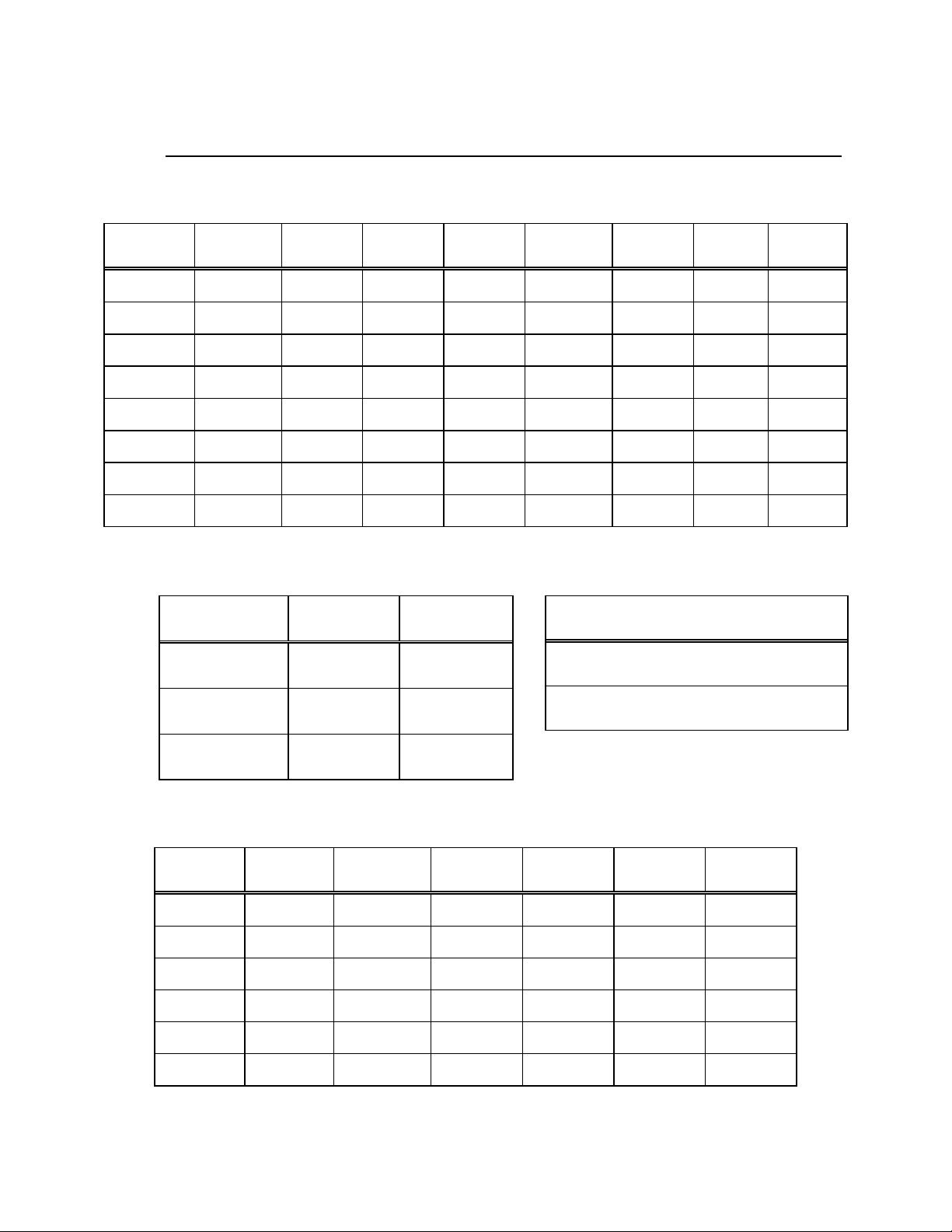
METRIC CONVERSIONS
Units of Length
Unit
1 centimeter — 0.3937 0.03281 0.01094
1 inch 2.540 — 0.08333 0.2778
1 foot 30.480 12.0 — 0.3333
1 yard 91.44 36.0 3.0 —
Centimeter
Inch
Foot
Yard
Mile
6.214 x 10
1.578 x 10
1.893 x 10
5.679 x 10
Meter
-6
-5
-4
-4
0.01 — —
0.254 — 25.4
0.3048 — —
0.9144 — —
Kilometer Millimeter
1 meter 100.0 39.37 3.281 1.094
1 mile
1 mm — 0.03937 — — — — — —
1 kilometer — — — — 0.621 — — —
1.609 x 10
5
6.336 x 10⁴ 5.280 x 10³ 1.760 x 10³
6.214 x 10
-4
—
— — —
1.609 x 10³
1.609 —
Temperature Conversions
Unit
32° Fahrenheit
212° Fahrenheit
-459.6° Fahrenheit
° Fahrenheit
—
—
—
° Centigrade
0
(water freezes)
100
(water boils)
273.1
(absolute 0)
Formulas
C = (F - 32) * 0.555
F = (C * 1.8) + 32
Units of Weight
Unit
1 gram — 0.03527 0.03215 0.002205 0.002679 0.001
Gram
Ounce
Avoirdupois
Ounce
Troy
Pound
Avoir.
Pound
Troy
Kilogram
1 oz. avoir. 28.35 — 0.9115 0.0625 0.07595 0.02835
1 oz. troy 31.10 1.097 — 0.06857 0.08333 0.03110
1 lb. avoir. 453.6 16.0 14.58 — 1.215 0.4536
1 lb. Troy 373.2 13.17 12.0 0.8229 — 0.3732
1 kilogram
1.0 x 10
3
35.27 32.15 2.205 2.679 —
Page 96

2114 WEST 7TH STREET TEMPE ARIZONA 85281 USA
480 • 333 • 2200 PHONE
480 • 333 • 2161
FAX
 Loading...