

Page 1

NetPerformer® SDM-9600 with SDM-9606 Blades
Hardware Installation Guide
Page 2

COPYRIGHTS AND DISCLAIMERS
Published Date: October 2013
Document # 1659 current revision tracker
This publication contains information proprietary and confidential to Memotec Inc. Any reproduction,
disclosure or unauthorized use of this publication is expressly prohibited except as Memotec Inc. may
otherwise authorize in writing.
Memotec Inc. reserves the right to make changes without notice in product or component design as warranted
by evolution in user needs or progress in engineering or manufacturing technology. Changes which affect the
operation of the unit will be documented in the next revision of the manual.
We have made every effort to ensure the accuracy of the information presented in our documentation.
However, Memotec assumes no responsibility for the accuracy of the information published. Product
documentation is subject to change without notice. Changes, if any, will be incorporated in new editions of
these documents. Memotec may make improvements or changes in the products or programs described within
the documents at any time without notice. Mention of products or services not manufactured or sold by
Memotec is for informational purposes only and constitutes neither an endorsement nor a recommendation for
such products or services.
Memotec Inc. is a wholly owned subsidiary of Comtech EF Data Corp., and its parent company Comtech
Telecommunications Corp (NASDAQ: CMTL).
AccessView, CXTool, CX-U Series, CX-UA Series, AbisXpress, NetPerformer, AccessGate, ACTView,
SDM-8400, and the SDM-9000 series of products are either registered trademarks or trademarks of Memotec
Inc.in Canada, the United States of America, and in other countries.
artf3363
Windows is a registered trademark of Microsoft Corporation in the United States and other countries.
Whatsup and WhatsupGold are registered trademarks of Ipswitch Inc. in the United States and other countries.
Any other trademarks are the property of their respective companies.
7755 Henri Bourassa Blvd. West
Montreal, Quebec
Canada H4S 1P7
Page 3

Contents
Chapter 1: Preface. . . . . . . . . . . . . . . . . . . . . . . . . . . . . . . . . . . . . . . . . . . . . . . . . . . . . . . . . 1-1
1. 1 About this Document . . . . . . . . . . . . . . . . . . . . . . . . . . . . . . . . . . . . . . . . . 1-2
1. 2 Audience . . . . . . . . . . . . . . . . . . . . . . . . . . . . . . . . . . . . . . . . . . . . . . . . . . 1-3
1.2.1 Instructions to the Reader . . . . . . . . . . . . . . . . . . . . . . . . . . . . . 1-3
1. 3 Product Overview . . . . . . . . . . . . . . . . . . . . . . . . . . . . . . . . . . . . . . . . . . . 1-4
1.3.1 SDM-9600 Chassis . . . . . . . . . . . . . . . . . . . . . . . . . . . . . . . . . . 1-4
1.3.2 SDM-9606 Blade . . . . . . . . . . . . . . . . . . . . . . . . . . . . . . . . . . . . 1-4
1.3.3 NetPerformer Software . . . . . . . . . . . . . . . . . . . . . . . . . . . . . . . 1-5
1.3.4 Changes to Console Operations . . . . . . . . . . . . . . . . . . . . . . . . 1-5
1. 4 Related Documents. . . . . . . . . . . . . . . . . . . . . . . . . . . . . . . . . . . . . . . . . . 1-6
1.4.1 NetPerformer Document Set . . . . . . . . . . . . . . . . . . . . . . . . . . . 1-6
1.4.2 Request for Comments . . . . . . . . . . . . . . . . . . . . . . . . . . . . . . . 1-6
1.4.3 Training . . . . . . . . . . . . . . . . . . . . . . . . . . . . . . . . . . . . . . . . . . . 1-7
1. 5 Technical Support . . . . . . . . . . . . . . . . . . . . . . . . . . . . . . . . . . . . . . . . . . . 1-8
1.5.1 Providing Product Numbers to Technical Support . . . . . . . . . . . 1-8
1.5.2 Product Serial Number. . . . . . . . . . . . . . . . . . . . . . . . . . . . . . . . 1-8
1.5.3 Product Work Order Number . . . . . . . . . . . . . . . . . . . . . . . . . . . 1-8
1.5.4 Checking the Contents of Your Product Package . . . . . . . . . . . 1-9
1.5.5 Returning an SDM-9600 Chassis or SDM-9606 Blade . . . . . . 1-10
1. 6 Sales Contacts. . . . . . . . . . . . . . . . . . . . . . . . . . . . . . . . . . . . . . . . . . . . . 1-11
Chapter 2: Compliance Information. . . . . . . . . . . . . . . . . . . . . . . . . . . . . . . . . . . . . . . . . . . 2-1
2. 1 Regulatory – Compliance and Agency Approval. . . . . . . . . . . . . . . . . . . . 2-2
2. 2 Compliance and Regulatory Statements. . . . . . . . . . . . . . . . . . . . . . . . . . 2-3
2.2.1 EU Directive 1999/5 . . . . . . . . . . . . . . . . . . . . . . . . . . . . . . . . . . 2-3
2.2.2 Marking . . . . . . . . . . . . . . . . . . . . . . . . . . . . . . . . . . . . . . . . . . . 2-5
2.2.3 Intent of Use and Network Compatibility . . . . . . . . . . . . . . . . . . 2-6
2.2.4 EN55022 and CISPR22 Warning. . . . . . . . . . . . . . . . . . . . . . . . 2-6
2.2.5 FERRITES (EMI Filters). . . . . . . . . . . . . . . . . . . . . . . . . . . . . . . 2-6
2.2.6 FCC Part 15 Statement . . . . . . . . . . . . . . . . . . . . . . . . . . . . . . . 2-7
2.2.7 Industry Canada Statements . . . . . . . . . . . . . . . . . . . . . . . . . . . 2-7
2.2.8 Notice d'Industrie Canada . . . . . . . . . . . . . . . . . . . . . . . . . . . . . 2-7
2. 3 Environmental Information. . . . . . . . . . . . . . . . . . . . . . . . . . . . . . . . . . . . . 2-8
2.3.1 Waste Electrical and Electronic Equipment – WEEE. . . . . . . . . 2-8
2.3.2 Restriction of Hazardous Substances - RoHS . . . . . . . . . . . . . . 2-9
Memotec Inc.
Page 4

2.3.3 Compliance to China RoHS. . . . . . . . . . . . . . . . . . . . . . . . . . . 2-10
2. 4 Safety Warnings and Precautions. . . . . . . . . . . . . . . . . . . . . . . . . . . . . . 2-11
2. 5 Making Changes or Modifications. . . . . . . . . . . . . . . . . . . . . . . . . . . . . . 2-11
Chapter 3: Unpacking the SDM-9600 . . . . . . . . . . . . . . . . . . . . . . . . . . . . . . . . . . . . . . . . . 3-1
3. 1 Selecting a Location . . . . . . . . . . . . . . . . . . . . . . . . . . . . . . . . . . . . . . . . . 3-2
3.1.1 Rack Requirements. . . . . . . . . . . . . . . . . . . . . . . . . . . . . . . . . . 3-2
3.1.2 Distance Requirements . . . . . . . . . . . . . . . . . . . . . . . . . . . . . . . 3-2
3.1.3 Environmental Requirements . . . . . . . . . . . . . . . . . . . . . . . . . . 3-2
3. 2 Preparing the Site . . . . . . . . . . . . . . . . . . . . . . . . . . . . . . . . . . . . . . . . . . . 3-3
3.2.1 What You Will Need. . . . . . . . . . . . . . . . . . . . . . . . . . . . . . . . . . 3-3
Chapter 4: Hardware Installation. . . . . . . . . . . . . . . . . . . . . . . . . . . . . . . . . . . . . . . . . . . . . 4-1
4. 1 About the Hardware Installation . . . . . . . . . . . . . . . . . . . . . . . . . . . . . . . . 4-2
4. 2 Installing the SDM-9600 Chassis in a Rack . . . . . . . . . . . . . . . . . . . . . . . 4-3
4. 3 Installing or Upgrading the DSP Modules . . . . . . . . . . . . . . . . . . . . . . . . . 4-4
4.3.1 Location of DSP Socket on the SDM-9606 Blade . . . . . . . . . . . 4-4
4.3.2 Installation Procedure . . . . . . . . . . . . . . . . . . . . . . . . . . . . . . . . 4-5
4. 4 Hardware Strapping for E1 Ports . . . . . . . . . . . . . . . . . . . . . . . . . . . . . . . 4-8
4.4.1 Strapping for E1-75 Operation. . . . . . . . . . . . . . . . . . . . . . . . . . 4-8
4. 5 Installing a Blade. . . . . . . . . . . . . . . . . . . . . . . . . . . . . . . . . . . . . . . . . . . . 4-9
4. 6 Removing a Blade. . . . . . . . . . . . . . . . . . . . . . . . . . . . . . . . . . . . . . . . . . 4-12
4. 7 Installing the Filler Panels . . . . . . . . . . . . . . . . . . . . . . . . . . . . . . . . . . . . 4-14
4. 8 Powering Up the Unit . . . . . . . . . . . . . . . . . . . . . . . . . . . . . . . . . . . . . . . 4-15
4.8.1 Connecting to the Power Source. . . . . . . . . . . . . . . . . . . . . . . 4-15
4.8.2 System Status on Power-up . . . . . . . . . . . . . . . . . . . . . . . . . . 4-16
4. 9 Connecting the Console Terminal. . . . . . . . . . . . . . . . . . . . . . . . . . . . . . 4-18
4.9.1 Important Console and Modem Settings for Startup . . . . . . . . 4-18
4.9.2 Activating the Console Connection . . . . . . . . . . . . . . . . . . . . . 4-19
4.9.3 Concerning HyperTerminal Connections. . . . . . . . . . . . . . . . . 4-20
4. 10 Installing the Licensed Software Options . . . . . . . . . . . . . . . . . . . . . . . . 4-21
4.10.1 Software License Key . . . . . . . . . . . . . . . . . . . . . . . . . . . . . . . 4-21
4. 11 Connecting the LAN Hub. . . . . . . . . . . . . . . . . . . . . . . . . . . . . . . . . . . . . 4-22
4. 12 Cleaning the Air Filter . . . . . . . . . . . . . . . . . . . . . . . . . . . . . . . . . . . . . . . 4-23
Chapter 5: Product Description. . . . . . . . . . . . . . . . . . . . . . . . . . . . . . . . . . . . . . . . . . . . . . 5-1
Memotec Inc.
Page 5

5. 1 SDM-9600 Chassis . . . . . . . . . . . . . . . . . . . . . . . . . . . . . . . . . . . . . . . . . . 5-2
5. 2 SDM-9606 Blade . . . . . . . . . . . . . . . . . . . . . . . . . . . . . . . . . . . . . . . . . . . . 5-2
5. 3 Optional Hardware. . . . . . . . . . . . . . . . . . . . . . . . . . . . . . . . . . . . . . . . . . . 5-2
5. 4 Base Unit Chassis . . . . . . . . . . . . . . . . . . . . . . . . . . . . . . . . . . . . . . . . . . . 5-3
5.4.1 Physical Dimensions . . . . . . . . . . . . . . . . . . . . . . . . . . . . . . . . . 5-4
5.4.2 Chassis System Status LEDs . . . . . . . . . . . . . . . . . . . . . . . . . . 5-4
5.4.3 Power Input Modules . . . . . . . . . . . . . . . . . . . . . . . . . . . . . . . . . 5-4
5.4.4 Fan Unit . . . . . . . . . . . . . . . . . . . . . . . . . . . . . . . . . . . . . . . . . . . 5-5
5.4.5 Air Filter . . . . . . . . . . . . . . . . . . . . . . . . . . . . . . . . . . . . . . . . . . . 5-6
5. 5 Blades for SDM-9600 Chassis. . . . . . . . . . . . . . . . . . . . . . . . . . . . . . . . . . 5-7
5.5.1 SDM-9606 Blade . . . . . . . . . . . . . . . . . . . . . . . . . . . . . . . . . . . . 5-7
5.5.2 System Status LEDs . . . . . . . . . . . . . . . . . . . . . . . . . . . . . . . . . 5-8
5. 6 Ethernet Ports . . . . . . . . . . . . . . . . . . . . . . . . . . . . . . . . . . . . . . . . . . . . . . 5-9
5.6.1 Ports. . . . . . . . . . . . . . . . . . . . . . . . . . . . . . . . . . . . . . . . . . . . . . 5-9
5.6.2 LAN Port Status LEDs . . . . . . . . . . . . . . . . . . . . . . . . . . . . . . . . 5-9
5.6.3 LAN Cables . . . . . . . . . . . . . . . . . . . . . . . . . . . . . . . . . . . . . . . . 5-9
5.6.4 RJ-45 Connector for Ethernet LAN Port. . . . . . . . . . . . . . . . . . 5-10
5. 7 DSP Modules. . . . . . . . . . . . . . . . . . . . . . . . . . . . . . . . . . . . . . . . . . . . . . 5-11
5.7.1 High-density DSP Modules . . . . . . . . . . . . . . . . . . . . . . . . . . . 5-11
5. 8 Console Port . . . . . . . . . . . . . . . . . . . . . . . . . . . . . . . . . . . . . . . . . . . . . . 5-13
5.8.1 Port. . . . . . . . . . . . . . . . . . . . . . . . . . . . . . . . . . . . . . . . . . . . . . 5-13
5.8.2 Console Cable . . . . . . . . . . . . . . . . . . . . . . . . . . . . . . . . . . . . . 5-13
5.8.3 RJ-45 Connector for Console Port. . . . . . . . . . . . . . . . . . . . . . 5-14
5. 9 E1/T1 Digital Interfaces . . . . . . . . . . . . . . . . . . . . . . . . . . . . . . . . . . . . . . 5-15
5.9.1 Ports. . . . . . . . . . . . . . . . . . . . . . . . . . . . . . . . . . . . . . . . . . . . . 5-15
5.9.2 E1/T1 Port Status LEDs. . . . . . . . . . . . . . . . . . . . . . . . . . . . . . 5-16
5.9.3 Supporting E1-75 on an E1/T1 Port. . . . . . . . . . . . . . . . . . . . . 5-16
5.9.4 Adaptor Cable . . . . . . . . . . . . . . . . . . . . . . . . . . . . . . . . . . . . . 5-17
5.9.5 E1/T1 Cables . . . . . . . . . . . . . . . . . . . . . . . . . . . . . . . . . . . . . . 5-18
Chapter 6: Troubleshooting Tips. . . . . . . . . . . . . . . . . . . . . . . . . . . . . . . . . . . . . . . . . . . . . 6-1
6. 1 Symptoms, Problems, and Solutions. . . . . . . . . . . . . . . . . . . . . . . . . . . . . 6-2
Chapter 7: Networking Features . . . . . . . . . . . . . . . . . . . . . . . . . . . . . . . . . . . . . . . . . . . . . 7-1
7. 1 GSM A-bis/A-ter Optimization . . . . . . . . . . . . . . . . . . . . . . . . . . . . . . . . . . 7-2
7. 2 Voice Channels . . . . . . . . . . . . . . . . . . . . . . . . . . . . . . . . . . . . . . . . . . . . . 7-3
7. 3 Network Connections. . . . . . . . . . . . . . . . . . . . . . . . . . . . . . . . . . . . . . . . . 7-4
Memotec Inc.
Page 6

7. 4 Network Management and Security . . . . . . . . . . . . . . . . . . . . . . . . . . . . . 7-5
Index . . . . . . . . . . . . . . . . . . . . . . . . . . . . . . . . . . . . . . . . . . . . . . . . . . . . . . . . . . . . . . . . . . . . 7
Memotec Inc.
Page 7

List of Figures
Location of Product Numbering on the SDM-9600 DC Nameplate . . . . . . . . . . . . . . . . . . . . . . . . 1-9
The SDM-9600 Chassis Equipped with SDM-9606 Blades . . . . . . . . . . . . . . . . . . . . . . . . . . . . . . 4-2
DSP Socket on the SDM-9606 Blade . . . . . . . . . . . . . . . . . . . . . . . . . . . . . . . . . . . . . . . . . . . . . . . 4-4
Inserting a DSP Module – Starting Position . . . . . . . . . . . . . . . . . . . . . . . . . . . . . . . . . . . . . . . . . . 4-6
Inserting a DSP Module – Final Position . . . . . . . . . . . . . . . . . . . . . . . . . . . . . . . . . . . . . . . . . . . . 4-7
Installing an SDM-9606Blade in the SDM-9600 Chassis . . . . . . . . . . . . . . . . . . . . . . . . . . . . . . . . 4-9
Blade Handle Operation . . . . . . . . . . . . . . . . . . . . . . . . . . . . . . . . . . . . . . . . . . . . . . . . . . . . . . . . 4-12
Rear View of the SDM-9600 Chassis with Filler Panels . . . . . . . . . . . . . . . . . . . . . . . . . . . . . . . 4-14
Accessing the Air Filter Tray . . . . . . . . . . . . . . . . . . . . . . . . . . . . . . . . . . . . . . . . . . . . . . . . . . . . 4-23
Air Filter and Outer Grill . . . . . . . . . . . . . . . . . . . . . . . . . . . . . . . . . . . . . . . . . . . . . . . . . . . . . . . . 4-24
Front View of the SDM-9600 Chassis Equipped with SDM-9606 Blades . . . . . . . . . . . . . . . . . . . 5-3
Rear View of the SDM-9600 Chassis . . . . . . . . . . . . . . . . . . . . . . . . . . . . . . . . . . . . . . . . . . . . . . . 5-3
Location of Fan Unit . . . . . . . . . . . . . . . . . . . . . . . . . . . . . . . . . . . . . . . . . . . . . . . . . . . . . . . . . . . . 5-5
Location of Air Filter . . . . . . . . . . . . . . . . . . . . . . . . . . . . . . . . . . . . . . . . . . . . . . . . . . . . . . . . . . . . 5-6
The SDM-9606 Blade . . . . . . . . . . . . . . . . . . . . . . . . . . . . . . . . . . . . . . . . . . . . . . . . . . . . . . . . . . . 5-7
Synchronous High-density DSP Module . . . . . . . . . . . . . . . . . . . . . . . . . . . . . . . . . . . . . . . . . . . . 5-11
RJ-48 to E1-75 Dual BNC Adaptor Cable . . . . . . . . . . . . . . . . . . . . . . . . . . . . . . . . . . . . . . . . . . 5-17
Memotec Inc.
Page 8

Memotec Inc.
Page 9

List of Tables
Compatible Telecom Services . . . . . . . . . . . . . . . . . . . . . . . . . . . . . . . . . . . . . . . . . . . . . . . . . . . . . 2-6
SDM-9606 Front Panel LED States During Normal Initialization Sequence . . . . . . . . . . . . . . . . 4-16
Feature items for the SDM-9600 chassis . . . . . . . . . . . . . . . . . . . . . . . . . . . . . . . . . . . . . . . . . . . . .5-2
Feature items for the SDM-9606 blade . . . . . . . . . . . . . . . . . . . . . . . . . . . . . . . . . . . . . . . . . . . . . .5-2
Feature items for optional hardware. . . . . . . . . . . . . . . . . . . . . . . . . . . . . . . . . . . . . . . . . . . . . . . . . 5-2
SDM-9606 ports . . . . . . . . . . . . . . . . . . . . . . . . . . . . . . . . . . . . . . . . . . . . . . . . . . . . . . . . . . . . . . . . 5-7
ST LED states. . . . . . . . . . . . . . . . . . . . . . . . . . . . . . . . . . . . . . . . . . . . . . . . . . . . . . . . . . . . . . . . . . 5-8
ALM LED states. . . . . . . . . . . . . . . . . . . . . . . . . . . . . . . . . . . . . . . . . . . . . . . . . . . . . . . . . . . . . . . . 5-8
RJ-45 pinout for Ethernet LAN port. . . . . . . . . . . . . . . . . . . . . . . . . . . . . . . . . . . . . . . . . . . . . . . .5-10
RJ-45 pinout for console port . . . . . . . . . . . . . . . . . . . . . . . . . . . . . . . . . . . . . . . . . . . . . . . . . . . . . 5-14
Status LED indicators on SDM-9606 digital interfaces . . . . . . . . . . . . . . . . . . . . . . . . . . . . . . . . . 5-16
RJ-48 pinout for E1/T1 ports . . . . . . . . . . . . . . . . . . . . . . . . . . . . . . . . . . . . . . . . . . . . . . . . . . . . . 5-18
Buffering scheme for packetization of DSP packets . . . . . . . . . . . . . . . . . . . . . . . . . . . . . . . . . . . . 7-3
Memotec Inc.
Page 10

Memotec Inc.
Page 11

Preface
1
Memotec Inc. 1-1
Page 12
SDM-9600 with SDM-9606 Blades Hardware Installation Guide
1.1 About this Document
This document, NetPerformer® SDM-9600 Hardware Installation Guide, provides the
following information about the SDM-9600 chassis installed with SDM-9606 blades:
• Unpacking instructions (“Unpacking the SDM-9600” on page 3-1)
• Hardware installation instructions (“Hardware Installation” on page 4-1)
• Product description (“Product Description” on page 5-1)
• Troubleshooting procedures (“Troubleshooting Tips” on page 6-1)
• Networking features (“Networking Features” on page 7-1)
• Notice concerning HyperTerminal connection (“Notice Concerning HyperTermi-
nal Connections” on page 8-1).
For information on configuring the NetPerformer, consult the NetPerformer System
Reference. See the “NetPerformer Document Set” on page 1-6 for a list of other
references.
NOTE: All NetPerformer documents are available on the NetPerformer
Documentation CD, which is included with your product package.
CAUTION: All documents on the NetPerformer Documentation
CD, including this guide, must be opened with Adobe™
Acrobat Reader 6.0, which is provided on the CD. If you open a
NetPerformer document with an earlier version of Acrobat Reader,
some of the text will not appear in its intended format. This can
make the text difficult or impossible to read correctly, especially
from a printed copy.
1-2 Memotec Inc.
Page 13
1.2 Audience
This document is intended for use by NetPerformer system administrators as well as
technicians who are qualified to set up, configure and troubleshoot a NetPerformer
Enterprise Network.
Installation of NetPerformer hardware requires knowledge and proficiency in the
configuration, operation, maintenance and security of all enterprise network elements in
your application. You should also have a thorough understanding of telecommunications
and be familiar with the networking strategies and telephony solutions currently used by
your organization.
1.2.1 Instructions to the Reader
Instructions to the reader include notes, cautions and warnings, which are distinguished
from the rest of the text by distinctive formatting and icons. Here is an example of each:
NOTE: A note may contain a reference, tip or other information related to the subject
at hand. The content of a note is intended to be helpful or of interest to the
reader.
Preface
CAUTION: A caution contains an instruction that the reader must
follow in order to prevent damage to equipment, network failure or
loss of data. The content of a caution must be read carefully and
explicitly obeyed.
WARNING: A warning contains an instruction that the reader must
follow in order to prevent electrical shock, death or serious injury
to personnel. The content of a warning must be read carefully
and explicitly obeyed.
Memotec Inc. 1-3
Page 14

SDM-9600 with SDM-9606 Blades Hardware Installation Guide
1.3 Product Overview
1.3.1 SDM-9600 Chassis
The NetPerformer SDM-9600 is a high-end chassis based on a standardized platform
architecture for carrier-grade telecommunication applications. It is ideal for large-scale
network applications such as GSM using point-to-point E1/T1 circuits, transport through
IP (terrestrial or satellite) or satellite Single Channel Per Carrier (SCPC) connections, and
Voice over IP (VoIP). Voice/data over PowerCell applications can use IP or WAN
connections and are able to integrate SCPC on digital or serial interfaces.
• PICMG 3.0 standard rack solution
• 19" rack-mountable
• -48 VDC (dual feed)
• Maximum 5 blades, loaded from the front
NOTE: All slots on the SDM-9600 must be installed with the same type of blade, in
this case, the SDM-9606.
• Hot swappable components
• Removable fan control module and air filter.
The basic software set provides support of PowerCell Voice and Data (including legacy
user data) and IP routing over Ethernet, serial or digital ports using PPP or Frame Relay
RFC-1490. Optional software licenses can be procured for support of GSM A-bis/ter,
SkyPerformer satellite access and TCP Acceleration.
1.3.2 SDM-9606 Blade
• Loads into front slots (maximum 5)
• Each blade has 6 built-in T1/E1 universal digital ports in the front (NT hardwired)
• Can be loaded with 1 DSP module
• Each blade has a capacity of up to 120 digital telephony channels
• A fully loaded SDM-9600 supports 600 simultaneous voice calls
• 1 RJ-45 console port
• 2 10/100 Ethernet ports
• Hot swap capability and power management control
• GSM and ATM capable.
1-4 Memotec Inc.
Page 15
1.3.3 NetPerformer Software
The basic software set provides support of PowerCell voice and data (including legacy
user data) and IP routing over Ethernet, serial or digital ports using PowerCell WAN, PPP
or Frame Relay RFC-1490. The GSM A-bis/A-ter software license is sold separately.
Optional software licenses can be procured for support of SkyPerformer satellite access
and TCP Acceleration.
1.3.4 Changes to Console Operations
The following change to console operations was made in NetPerformer firmware version
V9.2.0 and higher. If you are familiar with earlier versions of the NetPerformer firmware,
this change should be taken into consideration before you configure or manage the
product.
• The way you access the NetPerformer console has changed to allow for multiple
user profiles:
CAUTION: The default LOGIN is now ADMIN instead of ACT.
Preface
NOTE: The default PASSWORD for this login remains SETUP.
For full instructions on setting up user profiles, refer to the Quick Configuration module of
the NetPerformer Reference Guides.
Memotec Inc. 1-5
Page 16

SDM-9600 with SDM-9606 Blades Hardware Installation Guide
1.4 Related Documents
NOTE: All of the documents listed here are available on the NetPerformer
Documentation CD, which is included with your product package (Part No.
520-0081-001).
1.4.1 NetPerformer Document Set
For complete information on the NetPerformer, consult the following:
• NetPerformer System Reference
Includes detailed information on NetPerformer features, menus, commands,
parameters and statistics displays for versions V10.2.1 R02 and higher. This System Reference, which is divided into fascicles for each application, also integrates all information from the Addenda to the NetPerformer System Reference
Manual for versions 9.0.0, 9.1.0, 9.2.0 and 10.1.X.
• NetPerformer Hardware Installation Guides
These documents describe the hardware specific to each NetPerformer product,
including installable options, complete installation instructions and firmware
download procedures.
• NetPerformer Release Bulletins
These documents summarize the system specifications, software fixes and
changes, and post-production documentation changes for a particular NetPerformer release. They also include firmware upgrade procedures.
• NetPerformer Network Design Guide
Offers valuable tips on how to design a NetPerformer application for maximum
efficiency, including an analysis of data and voice traffic throughput issues and
the impact of traffic flow. Provides examples of network setup and traffic measurement using various NetPerformer products.
1.4.2 Request for Comments
Our Technical Publications group welcomes your feedback. Please help us improve future
releases of this document by sending us your comments and suggestions. You can send
email to
docs@memotec.com.
1-6 Memotec Inc.
Page 17

1.4.3 Training
Preface
We offer a variety of classes to reduce your learning curve and make your employees
more productive. Students learn how to tailor NetPerformer products to meet their specific
business requirements. Each course is developed and delivered by certified instructors
who have in-depth expertise and extensive technical training experience.
To learn more about our training services, email our education facilities at
memotectraining@memotec.com.
Memotec Inc. 1-7
Page 18

SDM-9600 with SDM-9606 Blades Hardware Installation Guide
1.5 Technical Support
Memotec Technical Support is designed to meet your full range of support needs. From
basic service to mission-critical support, we are committed to ensuring your success with
NetPerformer products. We tailor different support plans to meet your evolving business
requirements. By employing state-of-the-art products and the latest technologies available,
we provide some of the fastest, most efficient service in the industry.
Our entire support organization is focused on complete customer satisfaction and
providing immediate solutions to your business needs.
You can contact Technical Support by calling or sending email to our helpdesk facilities:
Telephone: + (1) 514 738 4781 during regular business hours, EST (GMT-05:00)
Email:
Be prepared to provide the following information:
• Your name
• Company name
• Your location
• Telephone number
• Product serial numbers (see next section)
• Product work order number (see next section)
• Detailed problem description
• Remote access to the troubled unit via Telnet or dial-up modem.
MemotecSupport@memotec.com
1.5.1 Providing Product Numbers to Technical Support
You may be requested to provide the product serial number and work order number when
communicating with Technical Support.
1.5.2 Product Serial Number
The product serial number is provided on the nameplate on the underside of the SDM9606 blade (see
Figure 1-1).
1.5.3 Product Work Order Number
The product work order number provides the manufacturing year and month of your unit.
This may be required for RMA or inspection purposes. The work order number appears
1-8 Memotec Inc.
Page 19
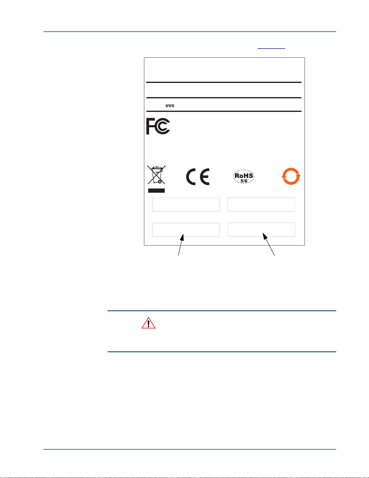
only on the nameplate on the underside of the blade (see Figure 1-1).
Memotec Inc.
Preface
Model:
_
48V
This Class A digital equipment meets all requirements of the Canadian
Interference-Causing Equipment Regulations
Cet appareil numérique de la Classe A respecte toutes les exigences du
Règlement sur le Matériel Brouilleur du Canada.
SDM-9600 DC
3A max
Complies with the limits for Class A digital device, pursuant to
Part-15 of the FCC rules..
50
Sellable #
S/N:
Product Serial Number
Base Unit #
W/O
MEMP37000108-C
Work Order Number
Figure 1-1: Location of Product Numbering on the SDM-9600 DC Nameplate
1.5.4 Checking the Contents of Your Product Package
CAUTION: As soon as you receive your SDM-9600 chassis and
components, check the carton and its contents for any sign of
damage during shipment. If there is any damage, contact the
shipping agent immediately.
Before you start SDM-9600 installation, verify the contents of the carton to ensure that
you have received all the units, blades, accessories, cables and optional hardware that you
ordered.
A summary of product items appears on “Product Description” on page 5-1.
If any items are missing, or if you have any questions concerning your shipment, contact
Technical Support.
Memotec Inc. 1-9
Page 20

SDM-9600 with SDM-9606 Blades Hardware Installation Guide
1.5.5 Returning an SDM-9600 Chassis or SDM-9606 Blade
If you need to return the SDM-9600 chassis or an SDM-9606 blade for any reason, you
must ship it in the original carton using adequate shock insulation material. Failure to
do so may void the equipment warranty. Consult the Warranty statements included with
the product package. Contact Technical Support for RMA requirements.
1-10 Memotec Inc.
Page 21

1.6 Sales Contacts
To order NetPerformer units, DSP modules, cables and optional parts, contact Memotec
Inc. or your NetPerformer distributor. To contact Memotec Inc.:
• Mail:
Memotec Inc.
7755 Henri Bourassa Blvd. West
Montreal, Quebec
Canada H4S 1P7
• Telephone: +1 (514) 738-4781 during regular business hours, EST (GMT-5:00)
• Fax: + (1) 514 738 4436
Preface
• Web:
http://www.memotec.com
Memotec Inc. 1-11
Page 22

SDM-9600 with SDM-9606 Blades Hardware Installation Guide
1-12 Memotec Inc.
Page 23

Compliance Information
2
Memotec Inc. 2-1
Page 24

SDM-9600 with SDM-9606 Blades Hardware Installation Guide
2.1 Regulatory – Compliance and Agency Approval
These products comply with or have obtained Regulatory Agency approval at least against
the following standards:
• EMC – Emission – Class A
• EMC – Immunity EN 55024:1998 + A1 + A2
• Safety EN 60950-1:2006 + A11
• Telecom – Digital
FCC Part 15
EN 55022:1998 + A1 + A2
TBR4
TBR 12 + TBR 13
2-2 Memotec Inc.
Page 25
Compliance Information
2.2 Compliance and Regulatory Statements
2.2.1 EU Directive 1999/5
DECLARATION OF CONFORMITY
We
declare under our sole responsibility that the NetPerformer product:
SDM-9600
Consisting of Model SDM-9600 DC
Equipped with the following blade:
- SDM 9606 blade (100-1210-501)
Equipped with the following cable
- RJ45 to Dual BNC (502-0459-001)
to which this declaration relates, is in conformity with all applicable essential
requirements following the provisions of the European Directive 1999/5/EC.
The conformity assessment procedure used for this declaration is the Annex II of the Directive.
Product compliance has been demonstrated against the following standards:
EN 55022 1998 + Amendments 1 and 2
EN 55024 1998 + Amendments 1 and 2
EN 60950-1 2006 + Amendment 11
The technical file is kept at:
Montreal, 11 March 2011
Stéphane Caron
Hardware Manager
Memotec Inc
7755 Blvd Henri Bourassa
Montreal, Quebec H4S 1P7
Canada
137-0026-001-B
Memotec Inc. 2-3
Page 26

SDM-9600 with SDM-9606 Blades Hardware Installation Guide
• MEMOTEC vakuuttaa täten että NetPerformer tyyppinen laite on direktiivin
1999/5/EY oleellisten vaatimusten ja sitä koskevien direktiivin muiden ehtojen
mukainen.
• Hierbij verklaart MEMOTEC dat het toestel NetPerformer in overeenstemming
is met de essentiële eisen en de andere relevante bepalingen van richtlijn 1999/5/
EG.
• Par la présente MEMOTEC déclare que l'appareil NetPerformer est conforme
aux exigences essentielles et aux autres dispositions pertinentes de la directive
1999/5/CE.
• Härmed intygar MEMOTEC att denna NetPerformer står I överensstämmelse
med de väsentliga egenskapskrav och övriga relevanta bestämmelser som framgår av direktiv 1999/5/EG.
• Undertegnede MEMOTEC erklærer herved, at følgende udstyr NetPerformer
overholder de væsentlige krav og øvrige relevante krav i direktiv 1999/5/EF.
• Hiermit erklärt MEMOTEC, dass sich dieses NetPerformer in Übereinstimmung
mit den grundlegenden Anforderungen und den anderen relevanten Vorschriften
der Richtlinie 1999/5/EG befindet. (BMWi).
• ΜΕ ΤΗΝ ΠΑΡΟΥΣΑ MEMOTEC ΔΗΛΩΝΕΙ ΟΤΙ NetPerformer
ΣΥΜΜΟΡΦΩΝΕΤΑΙ ΠΡΟΣ ΤΙΣ ΟΥΣΙΩΔΕΙΣ ΑΠΑΙΤΗΣΕΙΣ ΚΑΙ ΤΙΣ
ΛΟΙΠΕΣ ΣΧΕΤΙΚΕΣ ΔΙΑΤΑΞΕΙΣ ΤΗΣ ΟΔΗΓΙΑΣ 1999/5/ΕΚ.
• Con la presente MEMOTEC dichiara che questo NetPerformer è conforme ai
requisiti essenziali ed alle altre disposizioni pertinenti stabilite dalla direttiva
1999/5/CE.
• Por medio de la presente MEMOTEC declara que el NetPerformer cumple con
los requisitos esenciales y cualesquiera otras disposiciones aplicables o exigibles
de la Directiva 1999/5/CE.
• MEMOTEC declara que este NetPerformer está conforme com os requisitos
essenciais e outras disposições da Directiva 1999/5/CE.
• Hawnhekk, MEMOTEC, jiddikjara li dan NetPerformer jikkonforma mal-htigijiet essenzjali u ma provvedimenti ohrajn relevanti li hemm fid-Dirrettiva 1999/
5/EC.
• Käesolevaga kinnitab MEMOTEC seadme NetPerformer vastavust direktiivi
1999/5/EÜ põhinõuetele ja nimetatud direktiivist tulenevatele teistele asjakohastele sätetele.
• Alulírott, MEMOTEC nyilatkozom, hogy a NetPerformer megfelel a vonatkozó
alapvetõ követelményeknek és az 1999/5/EC irányelv egyéb elõírásainak.
• MEMOTEC týmto vyhlasuje, že NetPerformer spĺňa základné požiadavky a
všetky príslušné ustanovenia Smernice 1999/5/ES.
• MEMOTEC tímto prohlašuje, že tento NetPerformer je ve shodě se základními
požadavky a dalšími příslušnými ustanoveními směrnice 1999/5/ES.
2-4 Memotec Inc.
Page 27
Compliance Information
• Šiuo MEMOTEC deklaruoja, kad šis NetPerformer atitinka esminius reikalavimus ir kitas 1999/5/EB Direktyvos nuostatas.
• Ar šo MEMOTEC deklarē, ka NetPerformer atbilst Direktīvas 1999/5/EK
būtiskajām prasībām un citiem ar to saistītajiem noteikumiem.
• MEMOTEC izjavlja, da je ta NetPerformer skladu z bistvenimi zahtevami in
ostalimi relevantnimi dolo㶜ili direktive 1999/5/ES.
• Hér með lýsir MEMOTEC yfir því að NetPerformer er í samræmi við grunnkröfur og aðrar kröfur, sem gerðar eru í tilskipun 1999/5/EC.
• Niniejszym MEMOTEC oświadcza, że NetPerformer jest zgodny z zasadniczymi
wymogami oraz pozostałymi stosownymi postanowieniami Dyrektywy 1999/5/
EC.
• MEMOTEC erklærer herved at utstyret NetPerformer er i samsvar med de
grunnleggende krav og øvrige relevante krav i direktiv 1999/5/EF.
• Noi MEMOTEC declarăm că aparatul NetPerformer este în conformitate cu
cerinţele esenţiale şi cu alte prevederi relevante ale Hotărârii Guvernuluinr.88/
2003 şi Directivei 1999/5/EC
• MEMOTEC декларирам на своя отговорност, че далекосъобщително
устройство NetPerformer съответства на съществените изисквания по 1999/
5/EC
2.2.2 Marking
This Telecom equipment bears the following CE mark:
Memotec Inc. 2-5
Page 28

SDM-9600 with SDM-9606 Blades Hardware Installation Guide
2.2.3 Intent of Use and Network Compatibility
Item Compatible Telecom Services
With SDM-9606 blade
100-1210-501
This telecom Equipment is intended to be connected to the
following telecom services:
• ISDN Primary rate access at 2048 kbps in all the countries
• G.703 Leased circuits at 2048 kbps structured and
List of countries: Austria, Belgium, Bulgaria, Czech Republic,
Cyprus, Denmark, Estonia, Finland, France, Germany,
Greece, Hungary, Iceland, Republic of Ireland, Italy, Latvia,
Lithuania, Luxemburg, Malta, Netherlands, Norway, Poland,
Portugal, Romania, Slovakia, Slovenia, Spain, Sweden,
Switzerland, UK.
Table 2-1: Compatible Telecom Services
2.2.4 EN55022 and CISPR22 Warning
This is a Class A product that may cause radio interference. In this case, the user may be
required to take adequate measures.
2.2.5 FERRITES (EMI Filters)
listed below
unstructured, using 120 Ohm interface, in all the countries
listed below.
To ensure compliance in the European Union with the standard EN 55024:1998 + A1 +
A2, Ferrites are required on each RJ48 cable connected to an E1 port and on each cable
connected to an Ethernet port.
Simply clamp the ferrite onto the cable, approximately 1 inch away from the connector on
the chassis.
2-6 Memotec Inc.
Page 29

2.2.6 FCC Part 15 Statement
This digital equipment has been tested and found to comply with the limits
for a Class A digital device, pursuant to part 15 of the FCC Rules.
These limits are designed to provide reasonable protection against harmful interference
when t he equipment is operated in a commercial environment. This equipment generates,
uses and can radiate radio frequency energy and, if n ot installed and used in accordanc e
with the instruction manual, may cause harmful interference to radio communications.
Operation of this equipment in a residential area is likely to cause harmful interference,
in which case the user will be required to correct the interference at his or her own
expense.
2.2.7 Industry Canada Statements
This digital equipment does not exceed Class A limits for radio noise emissions for digital
apparatus, set out in Radio Interference Regulation of the Industry Canada. Operation in a
residential area may cause unacceptable interference to radio and TV reception requiring
the owner or operator to take whatever steps necessary to correct the interference.
This product meets the applicable Industry Canada technical specifications.
Compliance Information
2.2.8 Notice d'Industrie Canada
Cet équipement ne dépasse pas les limites de Classe A d'émission de bruits
radioélectriques pour les appareils numériques, telles que prescrites par le Règlement sur
le brouillage radioélectrique établi par l’Industrie Canada. L'exploitation faite en milieu
résidentiel peut entraîner le brouillage des réceptions de radio et de télévision, ce qui
obligerait le propriétaire ou l'opérateur à prendre les dispositions nécessaires pour en
éliminer les causes.
Memotec Inc. 2-7
Page 30

SDM-9600 with SDM-9606 Blades Hardware Installation Guide
2.3 Environmental Information
2.3.1 Waste Electrical and Electronic Equipment – WEEE
The WEEE (Waste Electrical and Electronic Equipment) legislation aims to raise the level
of recycling of electrical and electronic equipment and to encourage designers to create
products with recycling in mind.
The NetPerformer equipment that you bought has required the extraction and use of
natural resources for its production. It may contain hazardous substances that could impact
health and the environment.
In order to avoid the dissemination of those substances in our environment and to diminish
the pressure on the natural resources, we encourage you to use the appropriate take-back
systems. Those systems will reuse or recycle most of the materials of your end-of-life
equipment in a sound way.
The crossed-out wheeled bin symbol invites you not to dispose of WEEE as unsorted
municipal waste and to collect such WEEE separately.
If you need more information on the collection, reuse and recycling systems, please
contact your local or regional waste administration.
You can also contact us for more information on the environmental performances of our
products.
2-8 Memotec Inc.
Page 31

2.3.2 Restriction of Hazardous Substances - RoHS
RoHS - DECLARATION OF COMPLIANCE
We
declare that the NetPerformer product:
SDM-9600
Consisting of Model SDM-9600 DC
is in full compliance with the RoHS Directive 2002/95/EC of the European
Parliament and of the Council of 27 January 2003, on the restriction of the use of
the following substances in electrical and electronic equipment:
1- Mercury
2- Cadmium
3- Hexavalent chromium
4- Polybrominated biphenyls
5- Polybrominated diphenyl ethers
As permitted by item 7 of the Annex to the Directive 2002/95/EC, the SDM-9606
blades utilize the lead-in-solder exemption for Network Infrastructure
Equipment.
Compliance Information
The product bears the following label: RoHS-5/6
Montreal, 11 March 2011
Stéphane Caron
Hardware Manager
740-0504-001-C
Memotec Inc. 2-9
Page 32

SDM-9600 with SDM-9606 Blades Hardware Installation Guide
䶵⚗₼⦌ 5R+6
䜘Ԧ〠
ᴹ∂ᴹᇣ⢙䍘ᡆݳ㍐
䫵
⊎
䭹
ޝԧ䬜
ཊⓤ㚄㤟
ཊⓤҼ㤟䟊
᧕
⭥㔶
ᔰޣ
ᵪ㇡
仾ᡷ
2.3.3 Compliance to China RoHS
䶵
(Compliance to China RoHS)
(Hazardous Substances)
(Parts)
(Interface Cards)
(Cables)
(Switch)
(Chassis)
(Fans)
(Pb)
X
OOOOOO
OOOOOO
OOOOOO
OOOOOO
(Hg)
OOOOO
(Cd)
(CrV)
(PBB)
(PBDE)
O㺘⽪䈕ᴹ∂ᴹᇣ⢙䍘൘䈕䜘Ԧᡰᴹ൷䍘ᶀᯉѝⲴ䟿൷൘ SJ/T11363-2006 ḷ߶㿴ᇊⲴ䲀䟿㾱≲ԕлDŽ
Indicates that the concentration of the hazardous substance in all homogeneous materials in the parts is
below the relevant threshold of the SJ/T11363-2006 standard.
X 㺘⽪䈕ᴹ∂ᴹᇣ⢙䍘㠣ቁ൘䈕䜘ԦⲴḀа൷䍘ᶀᯉѝⲴ䟿䎵ࠪSJ/T11363-2006 ḷ߶㿴ᇊⲴ䲀䟿㾱≲DŽ
Indicates that the concentration of the hazardous substance of at least one of all homogeneous materials in
the parts is above the relevant threshold of the SJ/T11363-2006 standard.
2-10 Memotec Inc.
Page 33

2.4 Safety Warnings and Precautions
WARNING:
Warnung
Avertissement
Compliance Information
Access to the interior of this
unit shall be made only by a
qualified technician.
Remove power plug from
the power socket before
performing any service on
the unit.
To ensure adequate cooling
of the equipment, a 2-inch
unobstructed space must
be provided around all sides
of the unit.
The Power Socket shall be
installed near the equipment and shall be easily
accessible.
To prevent the risk of shock
or fire hazard, replace fuse
with same type and rating.
Der Zugang ins Innere des
Gerätes ist nur einem
fachlich qualifizierten Techniker gestattet.
Vorm Ôffnen des Gerätes
muss der Netzstecker yom
Stromnetz getrennt werden!
Um die Kühlung des
Gerätes nicht zu beeinträchtigen, ist es notwendig,
an allen Seiten des Gerätes
ca 5 cm Raum zu lassen.
Stellen Sie das Gerät in der
Nähe eines geer- deten
Schutzkontaktsteckers so
auf, dass der Stecker leicht
erreichbar und zugänglich
ist.
Zür Vermeidung der Stromschlag-und Feuergefahr
beim Auswechseln Sicherungen des gleichen Typs
und der gleichen Nennleistung einsetzen.
Seul un spécialiste doit
avoir accès à l'appareil.
Débranchez l'appareil avant
de l'ouvrir.
Afin de ne pas nuire au processus de refroidissement,
il est nécessaire de laisser
un espace d'environ 5 cm
de chaque côté de l'appareil.
Placez l'appareil près d’une
prise de courant facilement
accessible.
Afin d’éviter tout risque
d’incendie ou d’électrocution, remplacez les fusibles
par des fusibles de même
type et de même ampérage.
2.5 Making Changes or Modifications
CAUTION:Any changes and modifications not expressly approved
by Memotec Inc.
approval, and will void the user’s authority to operate the
equipment.
Memotec Inc. 2-11
will void any compliance and regulatory
Page 34

SDM-9600 with SDM-9606 Blades Hardware Installation Guide
2-12 Memotec Inc.
Page 35

Unpacking the SDM-9600
3
Memotec Inc. 3-1
Page 36

SDM-9600 with SDM-9606 Blades Hardware Installation Guide
3.1 Selecting a Location
To ensure that the SDM-9600 functions properly, you should install the unit in an
appropriate location which satisfies certain criteria for size, connection distance and
ambient environment.
3.1.1 Rack Requirements
The SDM-9600 chassis is designed with rackmount ears for installation in a rack:
• Standard 19" rack
• Near an easily accessible -48 VDC power supply.
• To ensure proper ventilation of the SDM-9600 and its components, leave 5 cm (2
inches) of unobstructed space around the unit chassis.
CAUTION: Unit must be installed in a restricted access location.
3.1.2 Distance Requirements
The SDM-9600 unit should be no more than 2 meters (approx. 6 feet) away from:
• A power supply appropriate to the type of power module on the unit: -48 VDC, 3
Amps maximum.
• An independent Ground.
WARNING: Ensure that the unit is independently grounded with a
wire from Ground securely attached to the ground lug on the SDM9600 chassis. The ground lug is located below the
LED at the front of the chassis.
3.1.3 Environmental Requirements
For trouble-free operation of the SDM-9600 its location must satisfy the following
environmental criteria:
• Operating temperature: 0C to 45C (32F to 113F)*
• Storage temperature: -20C to 65C (-4F to 149F)
POWER ON
• Relative humidity: 10% to 95%, non-condensing
3-2 Memotec Inc.
Page 37

• Maximum operating altitude: 4572 meters (15 000 feet)*
* NOTE:Above 3048 meters (10 000 feet) altitude the maximum operating temperature
of the unit drops from 45°C to 35°C.
• Ventilation requirement: leave 5 cm (2 inches) of unobstructed space around the
unit. All unused slots must be closed with a filler panel.
3.2 Preparing the Site
3.2.1 What You Will Need
For trouble-free installation of the SDM-9600 hardware make sure you have the following
on hand:
• The SDM-9600 chassis, with all SDM-9606 blades, accessories, cables and
optional hardware you received in the product package. Refer to “Product
Description” on page 5-1.
Unpacking the SDM-9600
• At least one of the following configuration and management access devices:
- A console terminal (TTY terminal or a PC equipped with terminal emulation
software) for direct or dial-up connection to the console port on the front face
of the SDM-9606 blade
- A TELNET network device accessed through IP connectivity over LAN/
WA N
NOTE: When you first take an SDM-9606 blade out of the box, the only configura-
tion device you can use is the console terminal, since the unit does not yet
have an IP address. For details, see “Connecting the Console Terminal” on
page 4-18.
CAUTION: If you intend to use the HyperTerminal
communications program as your console terminal, read the
“Notice Concerning HyperTerminal Connections” on page 8-1.
• A sufficient number and length of cables for all digital ports:
These cables are not provided with the SDM-9600 product package.
- One RJ-48 to RJ-48 cable for each E1/T1 port (at least 26AWG, or 0.4mm)
Memotec Inc. 3-3
Page 38

SDM-9600 with SDM-9606 Blades Hardware Installation Guide
- One crossover cable for each E1/T1 port that must provide a TE connection
(connecting to
NT equipment). All E1/T1 interfaces are strapped at the fac-
tory for NT mode
- Two BNC coaxial cables for each E1/T1 port that will be configured for E175 operations
An adaptor is also required for an E1-75 connection
on an E1/T1 port. The
following adaptors is available:
Adaptor cable: RJ-48 to E1-75 dual BNC (Part No. 161-0469-001). See
“Adaptor Cable” on page 5-17 for details.
- One straight through 10/100/1000BaseT LAN cable, RJ-45M to RJ-45M, for
each Ethernet port
• For all voice transmissions using PowerCell, an Internet connection or access to a
private IP network that supports the TCP and UDP/IP protocols.
PPP, Frame Relay (RFC1490) and WAN (PVCR) connections can be made without the requirement to support IP routing.
• All user equipment that will be directly connected to the digital ports.
3-4 Memotec Inc.
Page 39

Hardware Installation
4
Memotec Inc. 4-1
Page 40

SDM-9600 with SDM-9606 Blades Hardware Installation Guide
4.1 About the Hardware Installation
Figure 4-1: The SDM-9600 Chassis Equipped with SDM-9606 Blades
Hardware installation of the SDM-9600 involves the following steps:
• Installing the SDM-9600 chassis in a rack (“Installing the SDM-9600 Chassis in
a Rack” on page 4-3)
• Installing or upgrading a DSP module on the SDM-9606 blade (“Installing or
Upgrading the DSP Modules” on page 4-4)
• Hardware strapping on E1/T1 ports: Operation at 75 ohms (“Strapping for E1-75
Operation” on page 4-8)
• Installing a blade into the front of the SDM-9600 chassis (“Installing a Blade” on
page 4-9)
• Removing a blade (“Removing a Blade” on page 4-12)
• Installing the filler panels (“Installing the Filler Panels” on page 4-14)
• Powering up the unit (“Powering Up the Unit” on page 4-15)
• Connecting the console terminal (“Connecting the Console Terminal” on page 4-
18)
• Installing the licensed software options (“Installing the Licensed Software
Options” on page 4-21)
• (Optional) Connecting the unit to the LAN hub (“Connecting the LAN Hub” on
page 4-22)
In addition, the following maintenance procedure should be carried out on a regular basis:
• Cleaning the air filter in the SDM-9600 chassis (“Cleaning the Air Filter” on
page 4-23).
4-2 Memotec Inc.
Page 41

Hardware Installation
4.2 Installing the SDM-9600 Chassis in a Rack
The SDM-9600 chassis is designed with rackmount ears for installation in a standard 19"
rack (see Figure 4-1 on page 2). Rack requirements are discussed on page 2.
To install the SDM-9600 chassis in a rack:
1. Carefully insert the SDM-9600 chassis into the front of the rack
2. Secure each rackmount ear onto the rack using 2 mounting screws with washers.
Memotec Inc. 4-3
Page 42
SDM-9600 with SDM-9606 Blades Hardware Installation Guide
4.3 Installing or Upgrading the DSP Modules
Follow the procedure in this section for both installation and upgrade of a DSP module on
the SDM-9606 blade.
You need to have a DSP module to support voice/fax channels and GSM TRXs. This DSP
module is ordered separately from the unit and must be installed when you set up the
hardware at your site. For ordering information, refer to “Sales Contacts” on page 1-11.
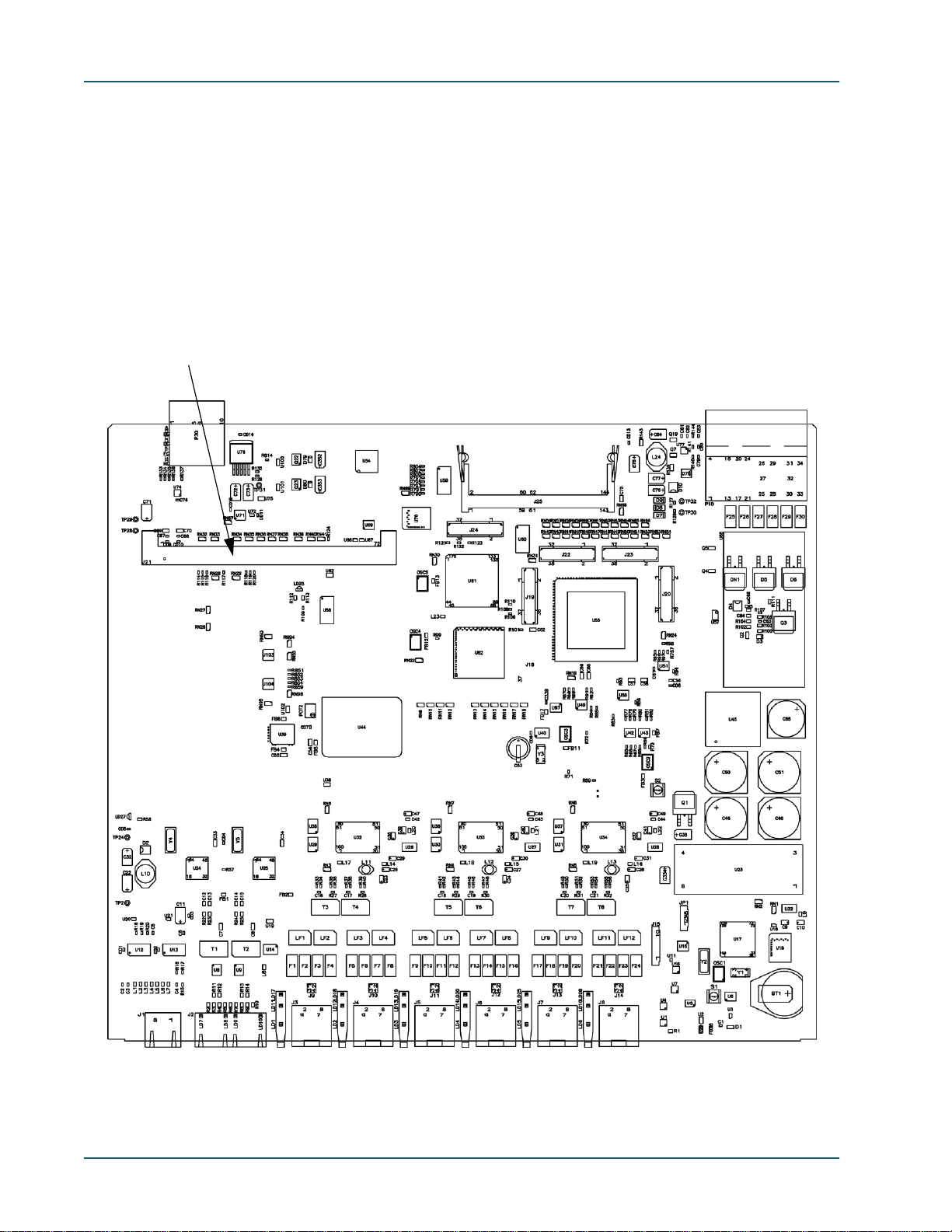
4.3.1 Location of DSP Socket on the SDM-9606 Blade
DSP Socket
Figure 4-2: DSP Socket on the SDM-9606 Blade
4-4 Memotec Inc.
Page 43

You can increase the number of voice channels supported by upgrading the DSP module.
Refer to “DSP Modules” on page 5-11 for a description of the different kinds of DSP
modules that can be installed.
CAUTION: These DSP modules are for the SDM-9210/9210GW, SDM-9220/
9220GW, SDM-9230/9230GW, SDM-9606 or SDM-9620 only. DO NOT use
a DSP module intended for the SDM-9360, SDM-9380 or SDM-9585.
NOTE: The SDM-9606 has one DSP socket for a single DSP module (see Figure 4-
2).
4.3.2 Installation Procedure
Hardware Installation
NOTE: To ensure proper digital voice operations and GSM traffic handling, install all
required DSP modules before you power up and configure the unit.
To install a DSP module:
1. Wear an ESD (Electrostatic Sensitive Devices) wrist strap, and attach it to one of the
ground lugs on the SDM-9600 chassis:
• Front ground lug, located beneath the
POWER ON LED. Refer to Figure 5-1.
• Rear ground lug, located to the right of the dual power input modules. Refer to
Figure 5-2.
CAUTION: Electrostatic charges can damage system components. Always use
an ESD wrist strap when accessing internal components of the unit.
In countries where a 2-pin non-grounded power cord must be used, ensure that the
SDM-9600 is independently grounded with a wire from Ground securely attached to
one of the ground lugs on the SDM-9600 chassis.
2. Locate the blade on which you want to install the DSP module. If this blade is already
installed in the SDM-9600 chassis, remove it as described in “Removing a Blade” on
page 4-12.
3. Place the blade on a hard, flat surface. Skip to step
6 if the DSP socket is empty.
4. If you are upgrading a DSP module that has already been installed:
Memotec Inc. 4-5
Page 44

SDM-9600 with SDM-9606 Blades Hardware Installation Guide
a. Locate the small metal clips that hold the DSP module into place at each
side of the DSP socket
b. Push the clips apart with the tips of your fingers. The DSP module will
spring to an angle of about 45°.
5. Holding the DSP module by its edge, carefully lift it up and out of its socket.
Caution: Do not expose the DSP module or SDM-9606 blade to a mag-
netic field or electrostatic charge at any time. Damage to their components
could result.
6. Carefully remove the new DSP module from its protective packaging.
7. Hold the DSP module over the DSP socket at an angle of about 45° with its notched
edge down. Center the module over the socket.
45° angle
Figure 4-3: Inserting a DSP Module – Starting Position
8. Insert the DSP module into the DSP socket:
a. First push the bottom edge of the DSP module all the way into the socket.
Use enough pressure to ensure that the DSP module is properly aligned
and fully inserted.
4-6 Memotec Inc.
Page 45

Hardware Installation
b. Press the top edge down until the module snaps into place between the
two metal clips at each end of the DSP socket.
NOTE: When properly installed, the DSP module should lie flat in its socket, beneath
the two metal clips.
CAUTION: Do not force the DSP module into the DSP socket. If the DSP
module does not snap into place easily or sit properly in the socket, make
sure you have inserted it with the notched edge down.
DSP lies flat
Figure 4-4: Inserting a DSP Module – Final Position
9. Reinstall the SDM-9606 blade into the SDM-9600 chassis. Refer to the procedure on
“Installing a Blade” on page 4-9.
Memotec Inc. 4-7
Page 46

SDM-9600 with SDM-9606 Blades Hardware Installation Guide
4.4 Hardware Strapping for E1 Ports
The E1/T1 interfaces on the SDM-9606 blade can be strapped for E1-75 operation
(see next section).
NOTE: No hardware strapping is required for NT/TE mode on these
interfaces. All E1/T1 interfaces ar e strapped at the factory as NT.
If you need a TE connection, attach a crossover cable to the interface.
For details about the E1/T1 ports, refer to “E1/T1 Digital Interfaces” on page 5-
15.
4.4.1 Strapping for E1-75 Operation
An E1-75 connection is accomplished by installing an adaptor on the E1/T1 port
(see “Supporting E1-75 on an E1/T1 Port” on page 5-16). The following adaptor
is available: RJ-48 to E1-75 dual BNC (Part No. AG2CA0001).
No other hardware strapping is required.
To set an E1/T1 port to E1-75, connect an adaptor for E1-75 operations onto the
digital port using an RJ-48 to E1-75 dual BNC adaptor cable (Part No.
AG2CA0001, see “Adaptor Cable” on page 5-17)
NOTE: Without an adaptor, the E1 port will not operate at 75 ohms.
CAUTION: The RJ-48 to E1-75 dual BNC adaptor cable and attached
BNC cables require strain relief to ensure that they do not loosen from
the digital port:
-If the unit is mounted in a rack, you must secure the cables to a side
rail using tie-wraps, or support the weight of the cables on a tray
-If the unit is on a table, you must support the weight of the cables on
the table.
The digital port can desynchronize and the unit reset if the full weight of the BNC
cables is unsupported.
4-8 Memotec Inc.
Page 47

4.5 Installing a Blade
The SDM-9606 blades are installed in slots at the front of the SDM-9600 chassis. Up to 5
blades can be installed. Refer to Figure 4-5.
NOTE: For easier installation and configuration, install all blades required for your
application before you power up and configure the unit. However, blades for
the SDM-9600 chassis are hot-swappable. The chassis does not need to be
powered down to insert another blade at a later time.
Hardware Installation
Figure 4-5: Installing an SDM-9606Blade in the SDM-9600 Chassis
To install a blade:
1. Wear an ESD (Electrostatic Sensitive Devices) wrist strap, and attach it to one of the
ground lugs on the SDM-9600 chassis:
• Front ground lug, located beneath the
POWER ON LED. Refer to Figure 5-1.
• Rear ground lug, located to the right of the dual power input modules. Refer to
Figure 5-2.
CAUTION: Electrostatic charges can damage system components. Always use
an ESD wrist strap when accessing internal components of the unit.
In countries where a two-pin non-grounded power cord must be used, ensure that the
SDM-9600 is independently grounded with a wire from Ground securely attached to
Memotec Inc. 4-9
Page 48

SDM-9600 with SDM-9606 Blades Hardware Installation Guide
one of the ground lugs on the SDM-9600 chassis.
2. Select an available blade slot on the front of the SDM-9600 chassis. These are the
wide slots labelled from
1 to 5 down the left side.
There is no loading sequence; any slot can be chosen. You do not need to disconnect
any cables connected to the ports on other blades.
3. If a filler panel is installed in the blade slot, remove it as follows:
a. Unscrew the 2 knurled M3 retention screws that hold the filler panel into
place on both sides
These screws can be loosened, but not removed.
b. Slide the filler panel out of the chassis, and set it aside.
Important: Keep the filler panel for possible reuse at a later time. To limit
electromagnetic interference and ensure optimum ventilation, there should be
no large openings in the SDM-9600 chassis. If you decide to remove a blade at a
later time, you will need to replace the filler panel for that slot.
4. Carefully remove the SDM-9606 blade from its protective packaging.
CAUTION: Do not expose the blade to a magnetic field or electrostatic charge at
any time. Damage to its components could result. Use ESD procedure at all
times.
5. Hold the blade so that the printing on its front panel is right side up, and slide it into
the slot from the front of the chassis.
CAUTION: Do not force the blade into the slot. If the blade is properly
aligned, it should slide easily all the way in along the guide rails provided.
6. Press the blade firmly into place, so that the two alignment holes at the rear of the
blade connect with the pins at the rear of the chassis slot.
When the front face of the blade is flush with the front of the chassis, the card
handles will close toward the center.
CAUTION: Carefully insert each blade fully into the unit. If a blade is not
correctly installed, proper contact cannot be made with the power source.
7. To secure the blade in place, press the 2 retention screws in and tighten them
clockwise.
8. Ensure that both card handles are pressed flat against the blade:
• Push the small lever into its housing on the card handle, then
4-10 Memotec Inc.
Page 49

Hardware Installation
• Press the handle back toward the front face of the blade.
NOTE: The right card handle is equipped with a microswitch that senses whether the
blade is fully inserted. It is very important that the card handles be fully
closed.
Memotec Inc. 4-11
Page 50

SDM-9600 with SDM-9606 Blades Hardware Installation Guide
4.6 Removing a Blade
Caution: Blades must be removed with care. Use ESD procedure at all times.
NOTE: Blades for the SDM-9600 chassis are hot-swappable, so the chassis does
not need to be powered down to remove a blade.
To remove a blade:
1. (Optional) Disconnect any cables that may be connected to the ports at the front of
the blade that you wish to remove.
2. Open both card handles slightly by pushing the lever in and opening the handle
toward you.
The blue H/S LED will blink, indicating that the blade is NOT READY to be
removed.
Caution: Do not remove the blade until the H/S LED has turned off.
3. When the
H/S LED has turned off, unscrew the two knurled M3 retention screws that
hold the blade into place on both sides.
These screws can be loosened, but not removed.
4. Pull the two card handles outward from the chassis, toward you.
The blade disengages from the pins at the rear.
Open outward
(toward you)
Left handle
Figure 4-6: Blade Handle Operation
4-12 Memotec Inc.
Page 51

Hardware Installation
5. Slide the blade the rest of the way out of the chassis.
Caution: Do not expose the blade to a magnetic field or electrostatic
charge at any time. Damage to its components could result.
6. Install a filler panel to cover the empty slot. Refer to the next section.
Memotec Inc. 4-13
Page 52

SDM-9600 with SDM-9606 Blades Hardware Installation Guide
4.7 Installing the Filler Panels
To limit electromagnetic interference and ensure optimum ventilation inside the SDM9600 chassis, there should be no large openings in the chassis. Each unused slot on both
the front and rear of the chassis requires a filler panel (Part No. 161-1140-000) to control
the air flow.
Example:
An SDM-9600 installed with a single SDM-9606 blade requires 9 filler panels, 4 in the
empty front slots and 5 in the empty rear slots. See Figure 4-7.
To install a filler panel:
1. Slide the filler panel through the slot opening, along the guide rails provided.
2. To secure the filler panel in place, press the 2 knurled M3 retention screws into the
panel, and tighten them by turning clockwise.
Figure 4-7: Rear View of the SDM-9600 Chassis with Filler Panels
Filler
Panels
4-14 Memotec Inc.
Page 53

4.8 Powering Up the Unit
4.8.1 Connecting to the Power Source
NOTE: Information about the power input modules is provided on “Power Input
Modules” on page 5-4.
CAUTION: This procedure must be carried out by a qualified electrical
technician only.
WARNING: A 20A circuit breaker must be provided as part of the
building installation for the -48VDC power connection.
Hardware Installation
To connect the SDM-9600 chassis to the power source:
1. Turn off the circuit breakers to the -48 volt DC power supply.
WARNING: To avoid electrical shock and possible damage to the
unit, ensure that the -48 VDC power supply is shut OFF before
you connect the SDM-9600 DC unit.
2. Ensure that all blades and filler panels are fully inserted into their slots and secured
in place.
3. Ensure that all wires of the -48 VDC connection harness have an appropriate
connector for installation onto a DC inlet.
CAUTION: Select a harness with a wire gauge capable of supporting a maximum
of 20 Amps.
4. Remove the clear plastic protector from one of the DC inlets located at the rear of the
SDM-9600 chassis, either
INPUT A or INPUT B, by removing the screws from the
two spacers on either side of the inlet lugs. Refer to Figure 5-2.
5. Install the harness to the DC inlet, terminating the wire connectors on the lugs
labelled
Memotec Inc. 4-15
-48V and RTN.
Page 54

SDM-9600 with SDM-9606 Blades Hardware Installation Guide
6. Connect the strip terminations of the harness wires to the -48 volt DC power supply.
7. Reinstall the clear plastic protector, ensuring that the harness wires come through the
hole in the bottom without obstruction. Tighten the two screws onto the spacers.
8. Turn on the circuit breakers to the -48 volt DC power supply.
9. Locate the power switch for the DC inlet you have selected, and turn the power switch
ON by pushing it to 1. The unit will begin power-up and system check immediately.
Warning: If at a later time you need to access internal components, turn OFF
the unit and the -48 VDC power supply, and disconnect the harness from the
DC inlet on the SDM-9600 DC chassis to avoid electrical shock and damage to
the unit.
4.8.2 System Status on Power-up
On power-up the SDM-9606 blades execute program decompression, Signaling Engine
software load and system test.
You can follow the system status from the console (see next section), or by watching the
LEDs on the front of the blades. Table 4-1 shows the various LED states that occur during
SDM-9606 initialization sequence (after a power-on or software reset).
NOTE: The entire startup sequence is executed within 30 seconds. Some of its stages
are brief, and may be difficult to distinguish from the rest..
Stage OOS ST ALM H/S Current Status of the Unit
1 Amber Blink Blink Blink Quick hardware test by the boot-
strap; lamp test on all LEDs. Blinking and frequent color changes
occur during this stage
2 Green Red Green Off Hardware initialization by the boot-
strap
3 Green Red Off Off Bootstrap is running. Preparing to
start the boot sector
4 Green Amber Off Off Boot sector is running. Validating
the application
5 Green Amber Amber Off Boot sector is running. Decom-
pressing the application
Table 4-1: SDM-9606 Front Panel LED States During Normal Initialization Sequence
4-16 Memotec Inc.
Page 55

Hardware Installation
Stage OOS ST ALM H/S Current Status of the Unit
6 Green Off Off Off Application has started from a
power-on
Red Off Application has started from a soft-
ware reset
7 Green Green Off Off Application has started from a
power-on; at least one link is up
Red Off Application has started from a soft-
ware reset; at least one link is up
Table 4-1: SDM-9606 Front Panel LED States During Normal Initialization Sequence
NOTE: If the OOS LED on the SDM-9606 blade stays amber, the unit may be faulty.
Contact Technical Support for assistance ( “Technical Support” on page 1-8).
See also “Troubleshooting Tips” on page 6-1 for other critical error situations.
Memotec Inc. 4-17
Page 56

SDM-9600 with SDM-9606 Blades Hardware Installation Guide
4.9 Connecting the Console Terminal
A console cable kit (Part no. 161-1066-001) is provided with the SDM-9606 product
package to connect your console terminal to the blade. This kit includes:
• A 14-ft. (4.25 m) console cable with RJ-45 male connectors at both ends, and
• A TIA-232 (V.24) terminal adaptor, RJ-45 female to DB-9 female.
NOTE: You can order an extra console cable kit from Memotec Inc. or your NetPer-
former distributor. Refer to “Sales Contacts” on page 1-11.
To connect the console terminal to the blade:
1. Install one end of the console cable onto the console port on the blade, labelled
Refer to Figure 5-5.
2. Connect the other end of the console cable to the RJ-45 female side of the terminal
adaptor.
3. Plug the DB-9 female side of the terminal adaptor into a COM port on the console
terminal or PC, or to a modem for dialup connection to a remote console.
4.9.1 Important Console and Modem Settings for Startup
The console port performs autobaud detection when in auto-sensing mode. The SDM9606 blade will set the speed of the console port as soon as it detects an active connection.
CAUTION: For trouble-free startup, you must set the console terminal and
modem as follows:
• Console terminal: The default console speed is 9600 bps during bootstrap ini-
tialization, boot sector validation and system initialization. Set your console ter-
minal emulator to 9600 bps to view all NetPerformer system status messages
on-screen during the startup sequence.
• Modem: Configure your modem with the following AT commands:
CSL.
-
at&d0 to ignore DTR. The SDM-9606 blade cannot supply DTR to the
modem when in auto-sensing mode (the default setting).
ats0=1 for Auto Answer mode
-
at&w0 to save the modem configuration.
-
Once system startup has completed successfully, the SDM-9606 blade enters auto-sensing
mode automatically. At that point, you can change your console speed, if desired.
4-18 Memotec Inc.
Page 57

• Available console speeds are 1200, 2400, 4800, 9600, 19200, 28800, 38400,
57600 and 115200 bps. The equipment you connect to the console port must
operate at one of these speeds.
4.9.2 Activating the Console Connection
To activate the console connection:
1. Ensure that all SDM-9606 blades have successfully powered up with no system status
errors (see “System Status on Power-up” on page 4-16).
2. Power the console terminal on or start your console terminal emulation program.
Take note of:
• “Important Console and Modem Settings for Startup” on page 4-18
• “Notice Concerning HyperTerminal Connections” on page 8-1.
Hardware Installation
3. When you see the prompt
T ype <ENTER> to connect, press the <Enter> key on the
console terminal keyboard several times, until the NetPerformer responds with a
prompt for the user login.
4. Enter the administrator login:
ADMIN.
This is the default login. Additional user logins can be defined. For details, refer to
the chapter
Configuration fascicle of the NetPerformer System Reference.
Controlling Access to the NetPerformer in the Quick
5. Enter the password for this login. The default password for the administrator login is
SETUP.
When the password is entered correctly, the SDM-9606 blade sends the product
banner to the console screen, as in this example:
LOGIN:ADMIN
PASSWORD:*****
ACCEPTED
SDM-9606 vx.x.x Memotec Technologies, Inc. (c) 2007
DSP QCxxx.BIZ code version: x.x.x
Console connected through TELNET
Voice transport method: PowerCell
Display commands, type HE
B3046082>
6. Enter the Display Alarms (DA) command at the NetPerformer console command line
to verify that your unit is problem free. In particular, look for any alarm messages that
indicate
Memotec Inc. 4-19
Call Technical Support.
Page 58

SDM-9600 with SDM-9606 Blades Hardware Installation Guide
4.9.3 Concerning HyperTerminal Connections
The HyperTerminal communications program comes with Microsoft Windows
products, and can be used for very basic NetPerformer console functions if no terminal
emulation program is available.
Caution: HyperTerminal is not recommended for adjusting the
NetPerformer configuration or monitoring its operations. Known problems
include the following:
• The arrow keys cannot be used to view channel status on all slots
• The console speed cannot be changed once the console connection is up and running
• On some computers, the default Emulation setting of the HyperTerminal
com-
munications program can potentially cause problems for console operations.
must use HyperTerminal for your console connection, you should change the
If you
Emulation setting from
Auto detect to ANSI, as follows:
1. Access HyperTerminal using the Windows Start button and drop-down menus:
Start > Programs > Accessories > Communications > HyperTerminal
2. If you have already defined the connection to the NetPerformer console port, open
that connection:
File > Open > your_filename.ht
3. If you have not yet defined the connection to the NetPerformer console port, create a
new connection:
File > New Connection > your_filename
4. Open the Properties window for the connection:
File > Properties
5. Click on the Settings tab to view the current value of the Emulation parameter.
6. Select the value
7. Click
OK.
ANSI from the list box for the Emulation parameter.
NOTE: The above procedure does not resolve the problems with arrow key func-
tionality or console speed, and should be considered a temporary solution
only. You should procure a more robust terminal emulation software program
for configuration and monitoring purposes. Contact Technical Support if you
need further assistance.
4-20 Memotec Inc.
Page 59

Hardware Installation
4.10 Installing the Licensed Software Options
Execute the Product License Status (PLS) command at the NetPerformer console
command line to install all licensed software options you have purchased for your SDM9606 blade.
Each licensed option includes a Software Licensing Agreement, which can be found in the
product package. You must agree to the terms and conditions of this agreement before
loading the software. Each NetPerformer unit or blade participating in the software
application must be installed with a separate software license.
4.10.1 Software License Key
The Memotec Software License Key is a traceable number that is used to activate the
licensed software option.
• This number is printed on an adhesive label on the cover of the licensed software
option product package
• Enter this number during execution of the
PLS command to activate the software
license
• You must then execute Reset Unit (
For details concerning installation of licensed software options, refer to the
Installation and Licensing module of the NetPerformer System Reference, which
is included on the
NetPerformer Documentation CD in the product package.
RU) command to apply the new license.
Software
Memotec Inc. 4-21
Page 60

SDM-9600 with SDM-9606 Blades Hardware Installation Guide
4.11 Connecting the LAN Hub
You must provide a standard straight through Ethernet 802.3 LAN cable (10/100/
1000BaseT, RJ-45M to RJ-45M) for connection to each LAN port.
NOTE: LAN cables are not provided with the SDM-9606 product package.
To connect the SDM-9606 blade to a LAN hub:
1. Connect one end of the LAN cable to one of the Ethernet LAN ports on the blade,
labelled
2. Connect the other end of the LAN cable to one of the 10/100/1000BaseT ports on
your local LAN hub.
ETH 1 and ETH 2. Refer to Figure 5-5.
3. The link is up when the
LAN connection:
- Amber: 100 Mbps
- Green: 10 Mbps.
LNK LED is on. The LED color indicates the speed of the
4-22 Memotec Inc.
Page 61

4.12 Cleaning the Air Filter
The air filter in the SDM-9600 chassis should be verified on a regular basis and cleaned
when required.
To clean the air filter:
1. Unscrew the M2.5 screw located near the center of the fan unit front panel. Refer to
Figure 4-8.
NOTE: This screw can be loosened, but not removed.
CAUTION: Do not unscrew the knurled M3 retention scr ew at the bottom of
the fan unit, which hold the fans in place.
2. Slide the air filter tray out of the SDM-9600 chassis.
Hardware Installation
Figure 4-8: Accessing the Air Filter Tray
Memotec Inc. 4-23
Page 62

SDM-9600 with SDM-9606 Blades Hardware Installation Guide
NOTE: If the air filter tray is difficult to remove, you can use the M3 retention screw
at the bottom of the fan unit as a gripping point.
3. The air filter is a black, washable fabric that adheres to the outer grill. Carefully peel
the air filter away from the outer grill.
Air filterOuter grill
Figure 4-9: Air Filter and Outer Grill
4. Wash the filter in a solution of warm water and mild detergent.
5. Rinse thoroughly in water and allow to dry completely before replacing the filter
in the fan unit.
WARNING: To prevent electrical shock and damage to the unit,
do not install a wet air filter into the SDM-9600 chassis.
6. When the air filter is dry, press it back into place on the outer grill of the air filter tray.
7. Slide the air filter tray into the SDM-9600 chassis, along the guide rail provided.
8. Push the air filter tray all the way back into place, so that its front face is flush with
the right rack bracket of the SDM-9600 chassis.
4-24 Memotec Inc.
Page 63

Product Description
5
Memotec Inc. 5-1
Page 64

SDM-9600 with SDM-9606 Blades Hardware Installation Guide
5.1 SDM-9600 Chassis
Item Details
Base unit chassis with 5 front slots for
SDM-9606 blades
2 redundant -48VDC power input modules
Fan unit, with removable air filter “Fan Unit” on page 5-5
5.2 SDM-9606 Blade
1 console port, with console cable “Console Port” on page 5-13
2 Ethernet ports (require customer-sup-
plied LAN cables and snap-on ferrites)
6 built-in E1/T1 interfaces (require cus-
tomer-supplied RJ-48 cables and snap-on
ferrites)
“Base Unit Chassis” on page 5-3
“Power Input Modules” on page 5-4
Table 5-1: Feature items for the SDM-9600 chassis
Item Details
“Ethernet Ports” on page 5-9
“E1/T1 Digital Interfaces” on
page 5-15
Table 5-2: Feature items for the SDM-9606 blade
5.3 Optional Hardware
Item Details
DSP modules: high-density “DSP Modules” on page 5-11
Table 5-3: Feature items for optional hardware
5-2 Memotec Inc.
Page 65

5.4 Base Unit Chassis
5 slots
for blades
1 slot
unavailable
for blade
Product Description
Rackmount Ears
Plastic
Protector
Card Handles
Figure 5-1: Front View of the SDM-9600 Chassis Equipped with SDM-9606 Blades
Power Input
Modules
Power ON/OFF Switches
POWER ON
LED
Ground
Lug
Ground Lug
Fan Unit
Filler Panels
Figure 5-2: Rear View of the SDM-9600 Chassis
Memotec Inc. 5-3
Page 66

SDM-9600 with SDM-9606 Blades Hardware Installation Guide
5.4.1 Physical Dimensions
• Width (chassis only): 43.58 cm (17.16")
• Width (with brackets): 48.26 cm (19.0")
• Depth (chassis only): 38.55 cm (15.18")
• Depth (including power input shields): 41.42 cm (16.31")
• Height: 22.48 cm (8.72")
• Weight (chassis only): 12.7 kg (28 lb)
• Typical weight (fully loaded): 15 kg (33 lb).
5.4.2 Chassis System Status LEDs
A POWER ON LED is provided on the front panel of the SDM-9600 chassis. This LED is
located on the right side of the unit when viewed from the front. Refer to
page 3.
POWER ON (green) goes on when the unit is powered on.
Figure 5-1 on
NOTE: Other system status LEDs are located on the SDM-9606 blades (OOS, ST,
ALM and H/S). See page 8.
5.4.3 Power Input Modules
Dual power input modules are located at the rear of the SDM-9600 chassis (see Figure 5-
2):
• 2 redundant power input modules
• DC power connectors
• 1 power switch on each power input module (
• Voltage: -48 VDC ± 5%, reverse polarity protected.
• Current: 6 Amps maximum
• SDM-9606 card maximum power consumption: 60 Watts.
NOTE: A harness with 2 m. (approx. 6 feet) of triple wire is required to connect the
unit to the power source. Connection should be carried out by a qualified
technician only. Refer to “Connecting to the Power Source” on page 4-15 for
instructions.
1 = ON, 0 = OFF)
5-4 Memotec Inc.
Page 67

5.4.4 Fan Unit
The fan unit, including fans and an air filter module, is located on the right side of the
SDM-9600 chassis when viewed from the front.
Product Description
Figure 5-3: Location of Fan Unit
• 2 fans, 290 cubic feet per minute, 24 VDC
• Provides cooling for up to 200 W per board
Memotec Inc. 5-5
Page 68

SDM-9600 with SDM-9606 Blades Hardware Installation Guide
5.4.5 Air Filter
Figure 5-4: Location of Air Filter
The air filter is:
• Washable fabric
• Velcro™-type adherence to outer grill
• Maintenance or replacement possible after opening the 1 U fan tray (refer to
“Cleaning the Air Filter” on page 4-23)
• No tools required for reassembly onto the fan tray.
5-6 Memotec Inc.
Page 69

5.5 Blades for SDM-9600 Chassis
5.5.1 SDM-9606 Blade
The SDM-9606 blade provides IP connectivity, E1/T1 universal digital ports, GSM and
voice traffic processing through an optional DSP module, and connection to the
NetPerformer command line interface.
Product Description
Card handle
Console port
Ethernet ports (2)
NOTE: On the NetPerformer console, SDM-9606 ports are identified as follows:
6 digital ports (T1/E1)
System status LEDs E1/T1 port status LEDs
Figure 5-5: The SDM-9606 Blade
Physical Port Port Number on Console (LINK)
CONSOLE CSL
ETH 1 (left) ETH1
ETH 2 (right) ETH2
1 (E1/T1 link) 100
2 (E1/T1 link) 200
3 (E1/T1 link) 300
4 (E1/T1 link) 400
Card handle
5 (E1/T1 link) 500
6 (E1/T1 link) 600
Table 5-4: SDM-9606 ports
Memotec Inc. 5-7
Page 70

SDM-9600 with SDM-9606 Blades Hardware Installation Guide
5.5.2 System Status LEDs
The following system status LEDs are located on the front face of the SDM-9606 blade:
OOS (Out Of Service; green/amber) goes on (green) when the blade is powered
•
on; turns amber when the card has failed in a chassis that has been powered on
ST (Status, red/amber/green) indicates the current program status on the blade, as
•
shown in
ALM (Alarm; red/amber/green) indicates several alarm states, including a system
•
alarm when a software reset occurs. See
H/S (Hot Swap: blue), located on the right side of the blade, goes on and blinks
•
when the card handles are opened, indicating that the blade is NOT READY for
removal. The blade can be removed when this LED turns off. Refer to “Remov-
ing a Blade” on page 4-12.
The E1/T1 port status LEDS are described on “E1/T1 Port Status LEDs” on page 5-16.
State Interpretation
Table 5-5
Table 5-6
Red
Amber
Off
Green
State Interpretation
Green Hardware initialization is in progress
Amber
Red
Early stages of system startup, when the bootstrap program is
running
Later stages of system startup, when the boot sector is running
Note: The exact function that is taking place can be determined
in conjunction with the ALM LED. Refer to Table 4-1
System startup complete. The application is running but no link
is up
The application is running and at least one link is up (specified
by the T1/E1 PORT LEDs)
Table 5-5: ST LED states
A Write operation to Flash memory is in progress, e.g. decom-
pressing the application during startup, saving the application
after a download
A software reset has occurred
Note: To turn the ALM LED off, enter the CE (Clear ERR/DIAG
LED) command at the console command line.
Off
5-8 Memotec Inc.
No alarm has occurred on the unit since the alarms were last
cleared
Table 5-6: ALM LED states
Page 71

5.6 Ethernet Ports
5.6.1 Ports
• 2 fully routed Ethernet IEEE 802.3 LAN interfaces
• RJ-45 10/100BaseT connectors
• Each port can be configured with 2 IP addresses
• Auto-detect speed, 10 or 100 Mbps
• Frame types: Ethernet II, IEEE 802.2, 802.3, SNAP
• Ethernet interface: Ethernet II and IEEE 802.2, 802.3
• Standards: IP RIP V1/V2 or Static, OSPF, NAT, IP Multicast IGMP V1/V2 PIMDM, BOOTP/DHCP Relay, DHCP client, IPX RIP and SAP, LLC2, 802.1p/q prioritization and VLAN, 802.1D Spanning Tree Protocol (STP), MAC Layer
• Filter Criteria: Based on protocol, address (source, destination or SAP) or custom
filtering.
For information on connecting to the LAN hub, refer to “Connecting the LAN Hub” on
page 4-22.
Product Description
5.6.2 LAN Port Status LEDs
Two LAN status indicators are located above each Ethernet port on the SDM-9606 blade
(refer to
Table 5-5). These LEDs indicate the following:
LNK: Indicates the LAN speed:
•
- Off: 10 Mbps
- Static green: 100 Mbps.
ACT: Blinks (green) when there is activity on the corresponding LAN port (LAN
•
traffic transmitted or received).
5.6.3 LAN Cables
Each Ethernet LAN port has an RJ-45 female connector to attach a LAN cable. Select a
standard LAN cable with RJ-45 connectors at both ends.
NOTE: Install a ferrite on each cable that connects to an Ethernet port: Steward ferrite
28A2029-0A0, Part No. 332-0003-000.
Memotec Inc. 5-9
Page 72

SDM-9600 with SDM-9606 Blades Hardware Installation Guide
5.6.4 RJ-45 Connector for Ethernet LAN Port
The RJ-45 female connectors marked ETH on the SDM-9606 blade provide two physical
LAN ports for attachment to the local LAN hub (10/100/1000Base-T, MDI connection).
The following table describes the RJ-45 pinout for a LAN port.
Pin No. Usage Description
1 TX+ Transmit (+) Output
2 TX- Transmit (-) Output
3 RX+ Receive (+) Input
4 – (not used)
5 – (not used)
6 RX- Receive (-) Input
7 – (not used)
8 – (not used)
Table 5-7: RJ-45 pinout for Ethernet LAN port
5-10 Memotec Inc.
Page 73

5.7 DSP Modules
On the SDM-9606 blade the DSP processors digitize, process and compress voice signals,
handle fax/modem emulation and, on units installed with the GSM A-bis/ter licensed
software option, perform A-bis/ter optimization and autodetection of GSM timeslot
subchannels.
• The SDM-9606 blade can be installed with either a synchronous low-density
DSP module (see next section) or a synchronous high-density DSP module (see
“High-density DSP Modules” on page 5-11). 1 DSP socket is provided on the
blade.
Refer to “Installing or Upgrading the DSP Modules” on page 4-4 for instructions on
installing the DSP modules. For ordering information, refer to “Sales Contacts” on page 1-
11.
NOTE: To determine whether any DSP modules are currently installed on the SDM-
9606 blade, power up the unit as described on “Powering Up the Unit” on
page 4-15. The DSP type is displayed with the product banner that appears
after boot-up is complete.
Product Description
5.7.1 High-density DSP Modules
The synchronous high-density DSP module (HD-DSP), which is the one type of DSP
supported on the SDM-9606 blade, can be installed on either the SDM-9606 blade to
support a greater number of GSM TRXs and voice calls.
Notched edge
Figure 5-6: Synchronous High-density DSP Module
A single synchronous high-density DSP module supports 60, 80, 100 or 120 timeslots.
Maximum 120 voice channels or 60 GSM TRXs per DSP.
CAUTION: The synchronous high-density DSP module is intended
for the SDM-9210/9210GW, SDM-9220/9220GW, SDM-9230/
9230GW, SDM-9606 and SDM-9620 only. DO NOT replace this
DSP module with a DSP intended for legacy NetPerformer
Memotec Inc. 5-11
Page 74

SDM-9600 with SDM-9606 Blades Hardware Installation Guide
products (SDM-9360, SDM-9380 and SDM-9585).
5-12 Memotec Inc.
Page 75

5.8 Console Port
5.8.1 Port
One PC-compatible console port:
• RJ-45 female connector
• TIA-232 (V.24) serial interface
• Autobaud asynchronous transmission, 1200, 2400, 4800, 9600, 19200, 28800,
38400, 57600 and 115200 bps
The equipment you connect to the console port must operate at 9600 bps when
you first power up the SDM-9606 blade. Also, if you are connecting to the console terminal via a modem, you must set the modem to ignore DTR. See
“Important Console and Modem Settings for Startup” on page 4-18.
• Autosensing gender, DTE/DCE
• Protocol: VT-100 or PPP
• Reverse console function also available for satellite applications (SkyPerformer).
Product Description
5.8.2 Console Cable
A console cable kit for the console port is included with the SDM-9606 product package
(Part no. 161-1066-001). This kit includes:
• 1 14-ft. (4.25 m) standard TIA-232 (V.24) straight-through cable with RJ-45 male
• 1 TIA-232 (V.24) adaptor for console terminal connection, RJ-45 female to DB-9
The console port (labelled
supplied console cable. Use the RJ-45 to DB-9 adaptor to connect the console cable to the
workstation that will serve as the console terminal. Refer to “Connecting the Console
Terminal” on page 4-18.
connectors at both ends, and
female
CSL) has an RJ-45 female connector to attach the factory-
Memotec Inc. 5-13
Page 76
SDM-9600 with SDM-9606 Blades Hardware Installation Guide
5.8.3 RJ-45 Connector for Console Port
The RJ-45 female connector marked CSL provides a physical port for attachment of the
console cable. It is a dedicated port with autosensing DTE/DCE mode and autobaud.
The following table describes the RJ-45 pinout for the console port.
Pin No. Usage Description
1 RTS Request T o Send
2 DTR DTE Ready
3 TXD Transmitted Data
4 SGND Signal Ground
5 DCD Carrier Detect
6 RXD Received Data
7 DSR DCE Ready
8 CTS Clear To Send
Table 5-8: RJ-45 pinout for console port
5-14 Memotec Inc.
Page 77

5.9 E1/T1 Digital Interfaces
5.9.1 Ports
6 digital ports are built into front of the SDM-9606 blade.
Each port has:
• E1/T1 channelized digital interface, RJ-48 female connector
• Supports from 15 to 120 channels (timeslots), depending on the number of DSPs
installed. These channels support TRXs on a unit installed with the GSM A-bis/
ter licensed software option, or voice connections on a base unit in PowerCell
mode. Refer to “Installing or Upgrading the DSP Modules” on page 4-4 for the
installation procedure.
• Two independent software configurable transceivers:
- T1 (DS1)/ISDN-PRI: Provides a 1.544 Mbps channelized digital connection
at 100 Ohms with up to 24 timeslots
- E1 (CEPT) PCM-30/ISDN-PRI: Provides a 2.048 Mbps channelized digital
connection with up to 32 timeslots, software selectable at 75 or 120 Ohms
Product Description
For hardware strapping of an E1-75 port, refer to “Hardware Strapping for E1
Ports” on page 4-8.
• Framing and line coding:
- T1: D4 or ESF framing and B8ZS, B7ZS or AMI line coding
- E1: G.704 framing and HDB3 line coding
• All ports are hard strapped as
a crossover cable where
• Add/drop capability with cross-connect: any incoming timeslot on any digital
port can be connected to any other timeslot on the same port, or any timeslot on
another digital port on the same blade or another blade installed in the same
SDM-9600 chassis.
NT by default for connection to TE equipment. Use
TE mode is required for connection to NT equipment.
Memotec Inc. 5-15
Page 78

SDM-9600 with SDM-9606 Blades Hardware Installation Guide
5.9.2 E1/T1 Port Status LEDs
Three LEDs are located to the left of each digital interface on the front face of the SDM9606 blade:
these LEDs should be interpreted.
SYN-AL (top), T1-E1 (middle) and D-CH (bottom). Table 5-9 explains how
LED Color Indication
Either the port is not configured (State = DISABLED) or
Off
Green The digital link is synchronized
SYN-AL
Amber
it did not pass the power-up self test and is not functional
One or more Y ellow Alarms have occurred on the link.
Note: The NetPerformer assumes that the physical
link is out of sync when a yellow alarm is
detected, and brings down any active channels
on that link
A fatal error has occurred, for example, loss of synchro-
nization on the digital link
Either the port is not configured or it did not pass the
power-up self test and is not functional
T1-E1
D-CH
Red
Off
Amber The port has been configured for T1 operation
Green The port has been configured for E1 operation
Off The D-channel is DOWN
Green The D-channel is UP
Table 5-9: Status LED indicators on SDM-9606 digital interfaces
5.9.3 Supporting E1-75 on an E1/T1 Port
An E1-75 connection requires an adaptor for E1-75 operations, as described in the next
section). You must provide strain relief for the cables to ensure that they do not loosen
from the digital port. See “Hardware Strapping for E1 Ports” on page 4-8.
5-16 Memotec Inc.
Page 79

5.9.4 Adaptor Cable
• RJ-48M to E1-75 dual BNC adaptor cable (Ordering part number: AG2CA0001)
Product Description
• Installed between the digital port and the BNC coaxial cable. Refer to
Dual BNC
connectors
RJ-48 connector
for E1 port
Figure 5-7: RJ-48 to E1-75 Dual BNC Adaptor Cable
page 8.
Memotec Inc. 5-17
Page 80

SDM-9600 with SDM-9606 Blades Hardware Installation Guide
5.9.5 E1/T1 Cables
You must provide an RJ-48 cable for each E1/T1 connection. Select a standard unshielded
twisted pair (UTP) male-male cable with RJ-48 connectors, at least 26AWG, or 0.4mm.
NOTE: Install a ferrite on each cable that connects to an E1/T1 port when installed
and operated in the European Union: Steward ferrite 28A2024-0A0, Part No.
332-0003-000.
The following table describes the RJ-48 pinout required for E1/T1 ports.
TE Mode NT Mode
Pin No. Signal Pin No. Signal
1 Receive (+) 1 Transmit
2 Receive (-) 2 Transmit
3 (not used) 3 (not used)
4 Transmit (+) 4 Receive
5 Transmit (-) 5 Receive
6 (not used) 6 (not used)
7 (not used) 7 (not used)
8 (not used) 8 (not used)
Table 5-10: RJ-48 pinout for E1/T1 ports
NOTE: An E1/T1 interface is hard-strapped as NT by default for connection to TE
equipment. Use a crossover cable where
TE mode is required for connection
to NT equipment.
5-18 Memotec Inc.
Page 81

Troubleshooting Tips
6
Memotec Inc. 6-1
Page 82

SDM-9600 with SDM-9606 Blades Hardware Installation Guide
6.1 Symptoms, Problems, and Solutions
Symptom Possible Problem Solution
Unit does not start, with:
OOS LED off
ST LED off
ALM LED off
Unit does not start, with:
OOS LED amber
ST LED any state
ALM LED any state
Unit starts, with:
OOS LED green
ST LED any state
ALM LED red
Unit starts, with an alarm
message of the type:
No power to unit Make sure the power harness is properly attached to
the power inlet on the uni.t, and to the DC power
supply
Check power harness and replace immediately if
damaged.
Make sure the DC power inlet has power.
Critical error. Unit
may be faulty
A software reset
occurred
A hardware error
occurred
Contact Technical Support for assistance (see
“Technical Support” on page 1-8).
Enter DA at the console command line to view the
alarms.
If a soft start (rst) alarm has been logged with the
notation M=xx A=xx D=xx, enter ER to dump the
Exit Record. Send to Technical Support.
Enter CE (Clear ERR/DIAG LED) to turn the ALM
LED off.
Enter DA at the console command line to view the
alarms.
An error has occurred
(0x00100000 0xC0000002),
please call the technical
support.
Console connection does not
work
Incorrect cable
connection
HyperTerminal
communications
program
Incorrect modem
setting
Contact Technical Support and provide alarm codes.
Make sure you are using the factory-supplied
console cable and RJ-45 to DB-9 terminal adaptor
Make sure the cable is properly plugged into the CSL
port and the console terminal COM port
Change Emulation parameter setting from Auto
detect to ANSI (see “Notice Concerning
HyperTerminal Connections” on page 8-1).
Set the modem to ignore DTR by executing the AT
command at&d0
Set the modem to Auto Answer mode: execute
ats0=1
6-2 Memotec Inc.
Page 83

Troubleshooting Tips
Symptom Possible Problem Solution
Console terminal displays
unreadable characters
Console terminal
was not set to the
default console
speed before startup
LAN connection does not work No power to LAN
hub
Incorrect cable
connection
Set your console terminal emulator to 9600 bps, and
start again
Make sure the DC power inlet has power
Make sure the LAN hub is properly plugged in and
switched on
If LNK LED is off, check LAN cable and replace if
damaged
If LNK LED is on, make sure you are using the
correct IP address for transmissions
Memotec Inc. 6-3
Page 84

SDM-9600 with SDM-9606 Blades Hardware Installation Guide
6-4 Memotec Inc.
Page 85

Networking Features
7
Memotec Inc. 7-1
Page 86

SDM-9600 with SDM-9606 Blades Hardware Installation Guide
7.1 GSM A-bis/A-ter Optimization
• Voice:
-FR
- EFR
-HR
- AMR 16K
- AMR 8K
• Data:
- GPRS (CS-1 to CS-4)
- EDGE (MSC-1 to MSC-9)
- HSCSD
• Signaling:
- 16K
- 32K
- 64K
- Concentrated and Non-Concentrated
• Fax, modem
• Short Message Service (SMS)
• Dual Rate
• Auto-detection of time slot assignments
• DS0 Cross connect
• SS7 FISU spoofing for A-ter signaling
7-2 Memotec Inc.
Page 87

7.2 Voice Channels
NOTE: Available with PowerCell transport (global Voice transport method parameter
set to PowerCell).
• Voice compression algorithms: ACELP-CN (8K/6K), G.729/G.729A (8K),
G.711 (PCM 64K), G.723 (low 5.3K/high 6.4K), G.726 (ADPCM 16K/24K/
30K/40K)
• Dialing: Multi-Frequency (MF), Dual Tone Multi-Frequency (DTMF) or Pulse
• Line activation: dedicated or switched
• Fallback: buffering scheme for packetization of DSP packets:
Compression Packetization Fallback (Buffering)
ACELP-CN 8K and 6K (configurable) up to 5
Networking Features
G.723 6.4K and 5.3K (configurable) up to 3
G.726 16K 16K none
G.726 24K 24K none
G.726 32K 32K none
G.726 40K 40K none
G.729, G.729A 8K up to 8
PCM64K 64K up to 2
Table 7-1: Buffering scheme for packetization of DSP packets
• Signaling: ISDN-PRI, QSIG
• Echo cancellation: CCITT G.165
• Fax Relay: Group III FAX 4.8, 7.2, 9.6, 12.0, 14.4 Kbps, over PowerCell or T.38
for SIP. Super G3 configurable to passthrough or fallback to G3. Group IV fax
and other non-voice bearer ISDN channel at 64K over VoIP
• Fax signal types: V.21 channel 2, V27ter 2400 bps, V27ter 4800 bps, V29 7200
bps, V29 9600 bps, V33 12000bps, V33 14400bps, V17 7200bps, V17 9600bps,
V17 12000bps, V17 14400bps
• Modem Relay: V.32bis demodulation up to 14.4 Kbps, modem passthrough
(G.711) for other modem types
• Encoding: Mu-law or A-law
Memotec Inc. 7-3
Page 88

SDM-9600 with SDM-9606 Blades Hardware Installation Guide
7.3 Network Connections
• Circuits: leased, switched, public and private Frame Relay
• Network topology: mesh, hierarchical, star, point-to-point, satellite point-topoint/multipoint (with SkyPerformer option)
• Automatic node discovery with least cost metric routing
• PPP dial backup, time-of-day connect
• PowerCell node discovery, load balancing, bandwidth on demand, dial backup
over leased line
• QoS: 8 classes of service, 16 priority weights, association to 802.1p and DiffServ
TOS bits
• PSTN digital (CAS)
• ISDN-PRI
7-4 Memotec Inc.
Page 89

7.4 Network Management and Security
• SNMP management and monitoring via SNMP-based network management system like HP Network Node Manager i (NNMi) software
• Menu-driven asynchronous console port (VT-100) via DB-9 male connector,
autosensing DTE/DCE
• Remote Telnet access to command port
• FTP or Zmodem upload and download of software and configuration
• Text-based configuration files and journal log
• Traps, traces and extended statistics
• Username/password security control
• Administrative filtering
Networking Features
Memotec Inc. 7-5
Page 90

SDM-9600 with SDM-9606 Blades Hardware Installation Guide
7-6 Memotec Inc.
Page 91

Index
A
Access methods 3-3
ACT LED
on LAN port
Air filter
cleaning
ALARM LED
Auto-detection
console port speed
gender
5-9
4-23
5-8
5-13
5-13
B
Blades 5-7
installing
removing
4-9
4-12
C
Cables 3-3
console port
E1/T1
E1-75 adaptor
LAN port
Chassis
Configuration access methods
Connectors
Console port
Console terminal
5-3
dimensions
LEDs
5-4
console port
LAN port
cable
5-13
speeds supported
activating connection to
connecting
startup setting
5-13
5-18
5-16
5-9
5-4
5-14
5-10
5-13
5-13
4-19
4-18
4-18
3-3
installation
location
4-5
4-4
E
E1/T1 cable 5-18
E1/T1 ports
LEDs
5-16
E1-75
cable
5-16
E1-75 operation
Environmental tolerances
Ethernet ports
4-8
3-2
5-9
H
H/S LED 5-8
Hardware
chassis
options
HyperTerminal
changing the Emulation setting
known problems
5-3
5-2
4-20
I
Indicators
chassis
E1/T1 ports
LAN port
Installation
blade
connecting to power source
console terminal
DSP module
LAN hub connection
location
requirements
resolving problems
5-4
5-16
5-9
4-9
4-18
4-4
4-22
3-2
3-3
6-1
4-20
4-15
D
Damage, avoiding 4-6, 4-10, 4-13
D-CH LED
Dimensions
Distance requirements
DSP module
installation
DSPs
SDM-9600 with SDM-9606 Blades Hardware Installation Guide Index-7
5-16
5-4
3-2
4-4
5-11
L
LAN hub, connecting 4-22
LAN port
LEDs
5-9
cable
5-9
current speed
LEDs
5-9
ACT
5-9
5-9
Page 92

ALARM 5-8
chassis
D-CH
E1/T1 ports
H/S
interpreting problems
LAN port
LINK
on SDM-9606 digital ports
OOS
POWER ON
STATUS
SYN-AL
T1-E1
LINK LED
Location
5-4
5-16
5-16
5-8
5-9
5-9
5-8
5-4
5-8
5-16
5-16
5-9
3-2
M
Modem
startup setting
4-18
6-1
5-16
Returning the unit
1-10
S
Sales contacts 1-11
SDM-9600 chassis
SDM-9606 blade
Security, specifications
Serial number
Site preparation
Solutions to common problems
Speed
console port
LAN port, viewing
Startup
system status
troubleshooting
STATUS LED
Strapping
E1-75
4-8
SYN-AL LED
5-2
5-2, 5-7
7-5
1-8
3-3
5-13
5-9
4-16
6-1
5-8
5-16
6-1
N
Network
management
management access methods
7-5
O
OOS LED 5-8
Optional hardware
Ordering information
5-2
1-11
P
Ports
cables
console
LAN
Power input modules
POWER ON LED
Power, connecting to
Power-up sequence
Product
package
Product numbers
5-9, 5-13
5-13
5-9
5-4
5-4
4-15
4-16
1-9
1-8
R
Rack requirements 3-2
Requirements
distance
environmental
location
materials
rack
3-2
3-2
3-2
3-3
3-2
3-3
T
T1-E1 LED 5-16
Troubleshooting tips
6-1
U
Unpacking 1-9
V
Voice interfaces
specifications
7-3
W
Work order number 1-8
8-Index Memotec Inc.
Page 93

SDM-9600 with SDM-9606 Blades Hardware Installation Guide Index-9
Page 94

REACH FURTHER. OFFER MORE.
Contact Memotec:
tel.: +1-514-738-4781
e-mail: MemotecSupport@memotec.com
7755 Henri Bourassa Blvd. West
Montreal, Quebec | Canada H4S 1P7 www.memotec.com
 Loading...