

Page 1

SDM-9000
p
Satellite Modem
Installation and O
Part Number MN/SDM9000.IOM Revision 4
eration Manual
Page 2

Page 3
Errata A
Comtech EFData Documentation Update
Subject:
Date:
Document:
Part Number:
Collating Instructions:
Comments:
The following changes provide updated information for Section 1.4.3, Table 1-4, Figures
1-6 and 1-7. This information will be incorporated into the next revision.
Change Specifics:
Added 8PSK and 16QAM information
June 6, 2000
SDM-9000 Satellite Modem Installation and Operation Manual
Part Number MN/SDM9000.IOM Rev. 4 dated May 5, 1997
MN/SDM9000.EA4
Attach this page to page 1-16
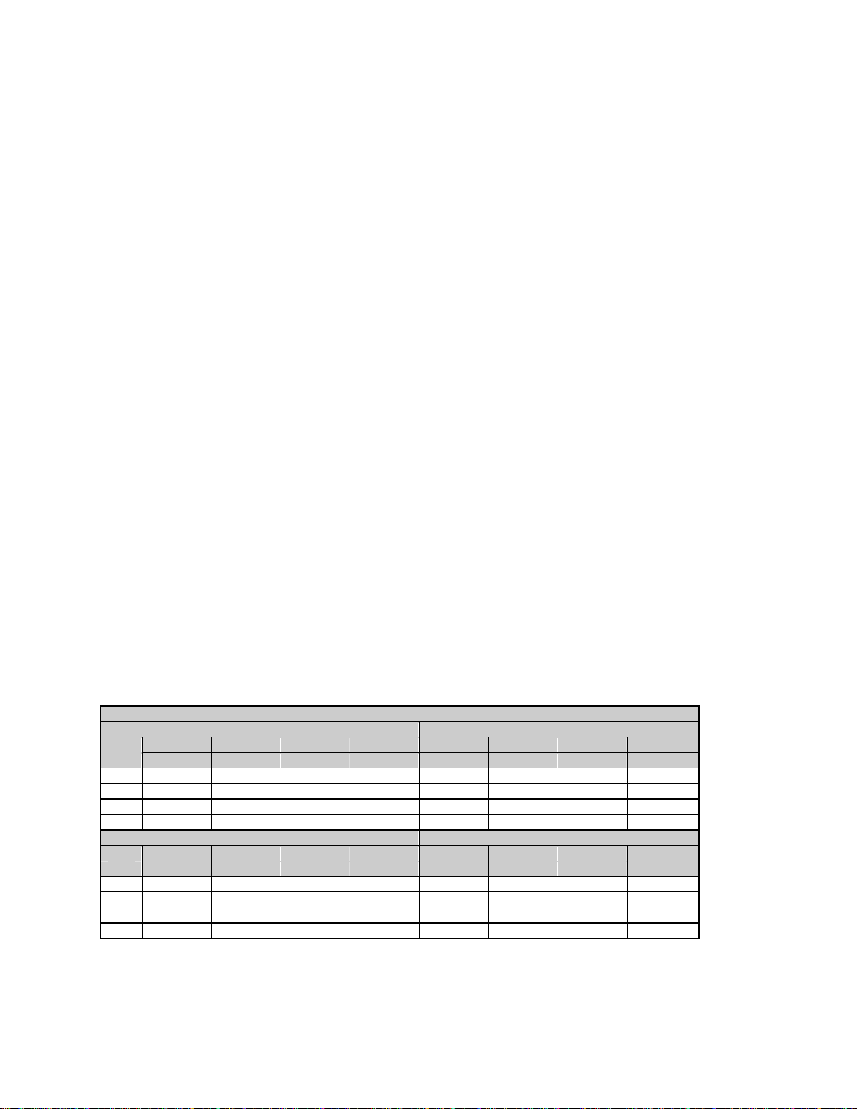
1.4.3 8PSK and 16QAM (Viterbi Decoder and Reed-Solomon Codec)
The 8PSK and 16QAM specifications for the Eb/N0 required to achieve 10-6 to
-9
10
BER with the Viterbi decoder and Reed-Solomon Codec are shown in
Table 1-4. Refer to Figures 1-6 (8PSK) and 1-7 (16QAM) for the BER curves
with the Reed-Solomon option.
Table 1-4. 8PSK and 16QAM BER Data
Specification
Without IDR With IDR
8PSK 8PSK 16QAM 16QAM 8PSK 8PSK 16QAM 16QAM
BER 2/3 Rate 5/6 Rate 3/4 Rate 7/8 Rate 2/3 Rate 5/6 Rate ¾ Rate 7/8 Rate
10-6 6.1 dB 8.2 dB 8.3 dB 9.8 dB 6.5 dB 8.6 dB 8.7 dB 10.2 dB
10-7 6.4 dB 8.5 dB 8.5 dB 10.0 dB 6.9 dB 8.9 dB 8.9 dB 10.4 dB
10-8 6.6 dB 8.9 dB 8.7 dB 10.3 dB 7.1 dB 9.3 dB 9.1 dB 10.7 dB
10-9 6.9 dB 9.3 dB 8.9 dB 10.5 dB 7.4 dB 9.7 dB 9.4 dB 10.9 dB
Typical Typical
8PSK 8PSK 16QAM 16QAM 8PSK 8PSK 16QAM 16QAM
BER 2/3 Rate 5/6 Rate 3/4 Rate 7/8 Rate 2/3 Rate 5/6 Rate 3/4 Rate 7/8 Rate
10-6 5.6 dB 7.7 dB 7.8 dB 9.4 dB 5.9 dB 8.1 dB 8.2 dB 9.8 dB
10-7 5.8 dB 7.9 dB 8.1 dB 9.7 dB 6.2 dB 8.3 dB 8.5 dB 10.1 dB
10-8 6.1 dB 8.4 dB 8.3 dB 9.9 dB 6.5 dB 8.9 dB 8.7 dB 10.3 dB
10-9 6.3 dB 8.7 dB 8.6 dB 10.2 dB 6.7 dB 9.1 dB 9.0 dB 10.6 dB
Note: Reed-Solomon parameters differ from open network and closed network. Open network
meets IESS-308 QPSK operation, using a 4-deep interleaver. Closed networks run different
Reed-Solomon parameters. A longer code word and an 8-deep interleaver is used, resulting in
better performance.
Page 4
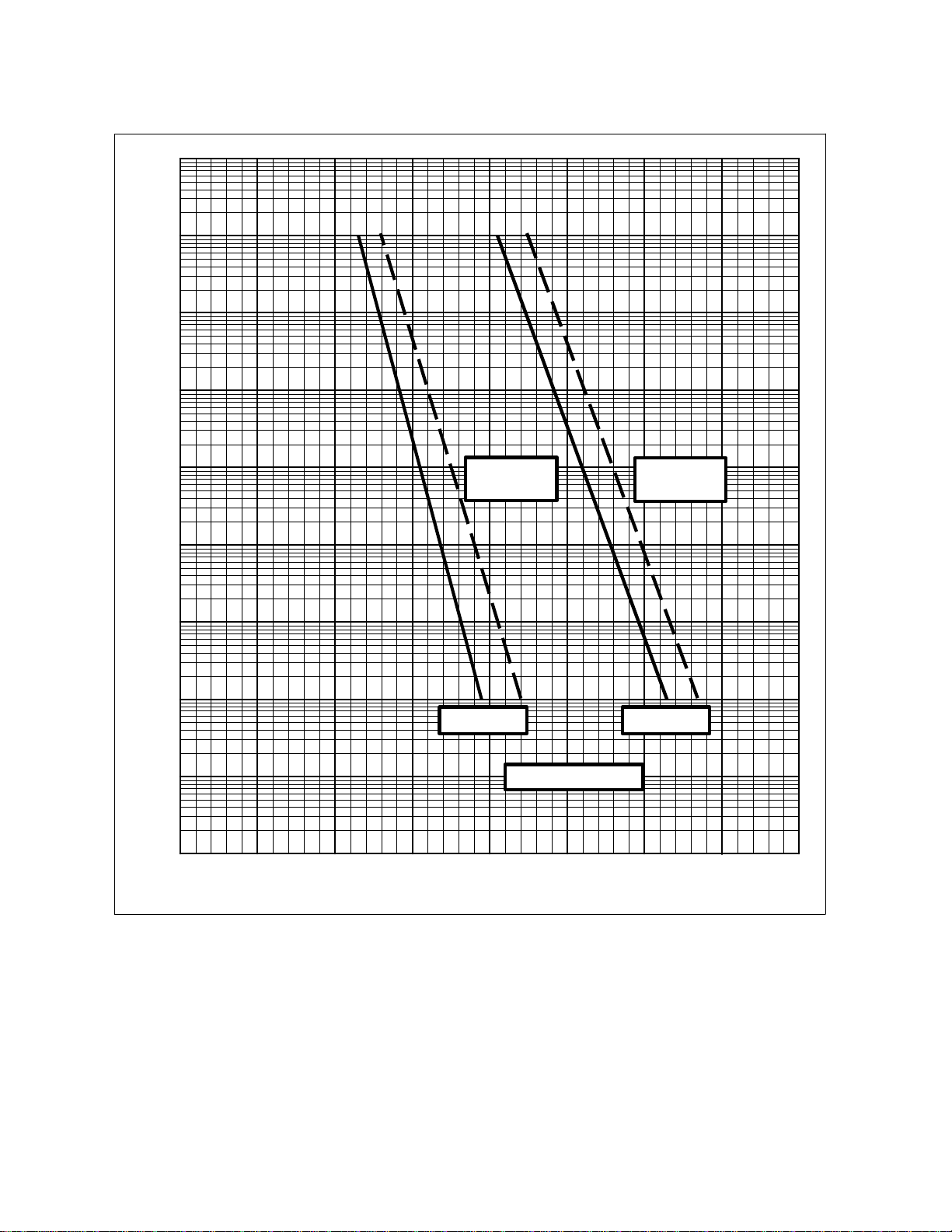
-2
10
-3
10
-4
10
-5
10
BER
-6
10
-7
10
-8
10
-9
10
-10
10
3.0 4.0 5.0 6.0
8 Mbit/s,
8PSK w/IDR
2/3 RATE
SPECIFICATIONS
8 Mbit/s,
8PSK w/IDR
5/6 RATE
7.0 8.0 9.0 10.0 11.0
(dB)
E
b/N0
Figure 1-6. 8PSK BER Performance Curves (with Reed-Solomon)
Filename: T_ERRATA 2
Page 5
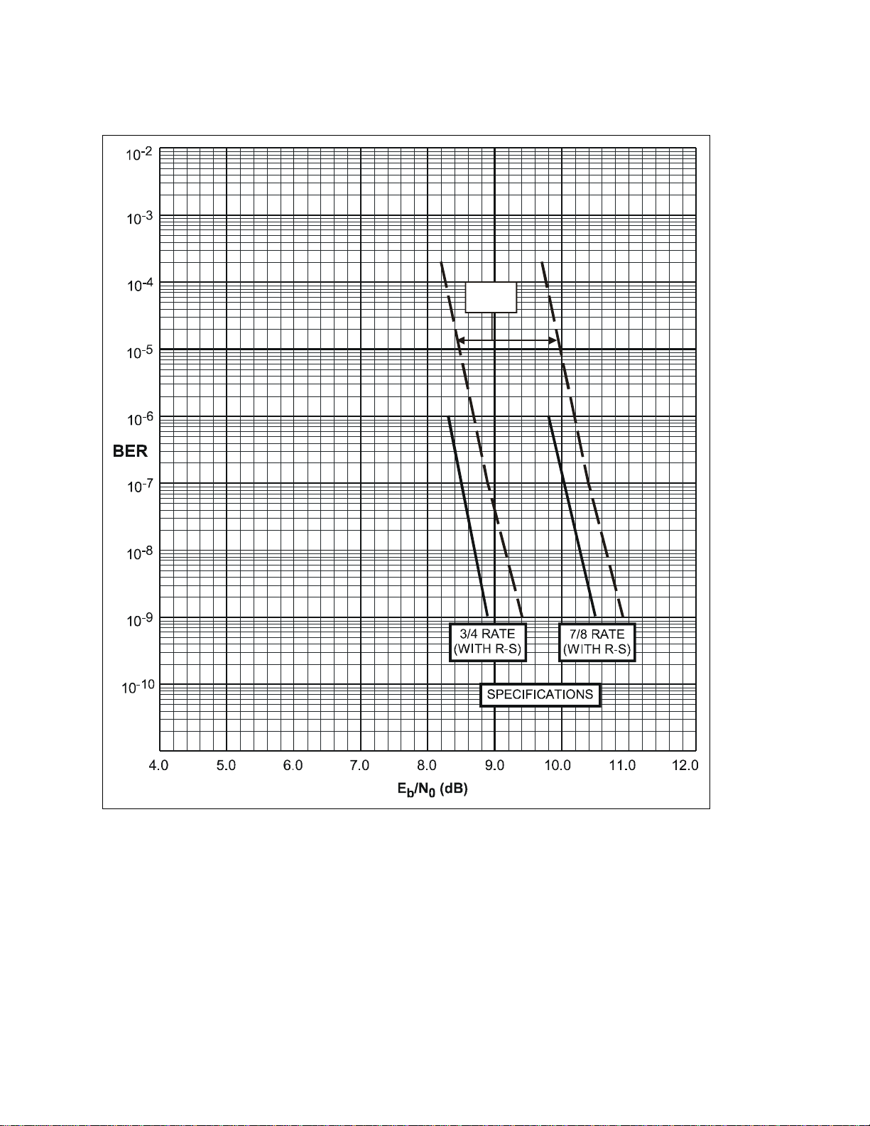
8 Mbit/s,
w/ IDR
Figure 1-7. 16QAM BER Performance Curves (with Reed-Solomon)
Filename: T_ERRATA 3
Page 6
Errata B
Comtech EFData Documentation Update
Subject:
Date:
Document:
Part Number:
Collating Instructions:
Comments:
The following changes provide updated information for page 2-15. This information will be
incorporated into the next revision.
Change Specifics:
2.4.10 Alarms (J10)
Changes to Note in Section 2.4.10, Alarms
January 19, 2001
SDM-9000 Satellite Data Modem Installation and Operation
Manual, Rev. 4, dated May 5, 1997
MN/SDM9000.EB4
Attach this page to page 2-15
The alarms connector is used to provide three Form C contact closures for alarm
reporting, as follows:
• Alarm 1 = Not used
• Alarm 2 = TX
• Alarm 3 = RX
The two Form C summary fault contacts currently used are:
• Transmit alarm (Alarm 2)
• Receive alarm (Alarm 3)
Refer to Chapter 4 for a discussion of alarms monitored. To obtain a system summary
alarm, connect all the Form C contacts in parallel.
The alarms connection is a 9-pin female D connector located on the rear panel of the
modem. Screw locks are provided for mechanical security on the mating connector.
Pin # Signal Function Name
1 NO
2 Alarm 1 COM
3 NC
4 NO
5 Alarm 2 COM
6 NC
7 NO
8 Alarm 3 COM
9 NC
Note: A connection between the common (COM) and normally closed (NC) contacts
indicates no alarm.
Filename: T_ERRATA 1
Page 7
Errata C
Comtech EFData Documentation Update
Subject:
Date:
Document:
Part Number:
Collating Instructions:
Comments:
The following changes provide updated information for Table 3-2. This information will be
incorporated into the next revision.
Changes to Table 3-2 (Modulator PCB Jumper Settings)
January 23, 2002
SDM-9000 Satellite Modem Installation and Operation Manual,
Rev. 4, dated May 5, 1997
MN/SDM9000.EC4
Attach this page to page 3-3
Change Specifics:
3.2 Modulator
The modulator PCB (AS/3969) is located in the top slot of the modem chassis. The jumper settings are
listed in Table 3-2. Figure 3-2 shows the modulator card and the jumper locations.
Table 3-2. Modulator PCB Jumper Settings
Jumper Position Function
J7 1 to 2
2 to 3
J9
(EEPROM size select)
Note: The modulator PCB jumpers in Table 3-2 are factory set.
1 to 2
2 to 3
Output forced ON, test mode
Normal, processor control
27C512 (64K EEPROM)
27C256 (32K EEPROM)
Filename: T_ERRATA 1
Page 8

Page 9

Comtech EFData is an ISO 9001
Registered Company.
SDM-9000
Satellite Modem
Installation and Operation Manual
Part Number MN/SDM9000.IOM
Revision 4
May 5, 1997
Comtech EFData, 2114 West 7th Street, Tempe, Arizona 85281 USA, (480) 333-2200, FAX: (480) 333-2161.
Copyright © Comtech EFData, 2000. All rights reserved. Printed in the USA.
Page 10

Customer Support
Contact the Comtech EFData Customer Support Department for:
•
Product support or training
•
Information on upgrading or returning a product
•
Reporting comments or suggestions concerning manuals
A Customer Support representative may be reached at:
Comtech EFData
Attention: Customer Support Department
2114 West 7th Street
Tempe, Arizona 85281 USA
(480) 333-2200 (Main Comtech EFData Number)
(480) 333-4357 (Customer Support Desk)
(480) 333-2161 FAX
or, E-Mail can be sent to the Customer Support Department at:
service@comtechefdata.com
Contact us via the web at www.comtechefdata.com.
1. To return a Comtech EFData product (in-warranty and out-of-warranty) for
repair or replacement:
2. Request a Return Material Authorization (RMA) number from the Comtech
EFData Customer Support Department.
3. Be prepared to supply the Customer Support representative with the model
number, serial number, and a description of the problem.
4. To ensure that the product is not damaged during shipping, pack the product in
its original shipping carton/packaging.
5. Ship the product back to Comtech EFData. (Shipping charges should be prepaid.)
For more information regarding the warranty policies, see Warranty Policy, p. xiv.
ii Rev. 4
Page 11

Table of Contents
CHAPTER 1. INTRODUCTION........................................................................................1–1
1.1 Overview................................................................................................................................................................. 1–2
1.1.1 Nyquist Filter Printed Circuit Boards............................................................................................................... 1–3
1.1.2 Description........................................................................................................................................................ 1–4
1.1.3 Options ................................................................................................................. ............................................1–6
1.1.3.1 Reed-Solomon Codec................................................................................................................................ 1–6
1.1.3.2 8PSK/16QAM........................................................................................................................................... 1–6
1.1.3.3 Direct Broadcast Satellite.......................................................................................................................... 1–7
1.2 Modem Assemblies................................................................................................................................................. 1–8
1.3 Modem Specifications............................................................................................................................................ 1–10
1.4 BER Performance Specifications.......................................................................................................................... 1–12
1.4.1 Viterbi Decoder BER (QPSK).......................................................................................................................... 1–12
1.4.2 Reed-Solomon Codec BER (QPSK)................................................................................................................. 1–14
1.4.3 8PSK and 16QAM (Viterbi Decoder and Reed-Solomon Codec).................................................................... 1–16
CHAPTER 2. INSTALLATION.........................................................................................2–1
2.1 Unpacking............................................................................................................................................................... 2–1
2.2 System Options....................................................................................................................................................... 2–2
2.3 System Installation................................................................................................................................................. 2–3
2.4 External Connectors.............................................................................................................................................. 2–5
2.4.1 TX/IF Output (CP1).......................................................................................................................................... 2–6
2.4.2 RX/IF Input (CP2)............................................................................................................................................ 2–6
2.4.3 Receive Data (CP3).......................................................................................................................................... 2–6
2.4.4 Send Data (CP4)............................................................................................................................................... 2–6
2.4.5 External Clock (CP5)........................................................................................................................................ 2–6
2.4.6 Remote (J6) ...................................................................................................................................................... 2–7
2.4.7 Fault (J7)........................................................................................................................................................... 2–8
2.4.8 DATA I/O (ESC) Interface (J8)........................................................................................................................ 2–9
2.4.8.1 G.703 (IDR) Interface (J8) (Audio Mode) ................................................................................................ 2–10
Rev. 4 iii
Page 12

Preface SDM-9000 Satelite Modem
2.4.8.2 G.703 (IDR) Interface (J8) (64 kbit/s Mode) ............................................................................................ 2–11
2.4.8.3 ECL Interface (J8)..................................................................................................................................... 2–12
2.4.8.4 MIL-STD-188 Interface (J8)..................................................................................................................... 2–13
2.4.9 AUX 1 (J9)....................................................................................................................................................... 2–14
2.4.10 Alarms (J10)................................................................................................................................................... 2–15
2.4.11 AC Power ....................................................................................................................................................... 2–16
2.4.12 DC Power ....................................................................................................................................................... 2–16
2.4.13 Ground (GND)................................................................................................................................................ 2–16
CHAPTER 3. CONFIGURATION.....................................................................................3–1
3.1 Display/M&C.......................................................................................................................................................... 3–1
3.2 Modulator............................................................................................................................................................... 3–3
3.3 Demodulator........................................................................................................................................................... 3–4
3.4 Interface.................................................................................................................................................................. 3–5
3.5 Nyquist Filter Configuration................................................................................................................................. 3–9
3.5.1 Compatibility.................................................................................................................................................... 3–10
3.5.2 Installation........................................................................................................................................................ 3–10
3.5.2.1 Unpacking Instructions.............................................................................................................................. 3–10
3.5.2.2 Tools Required.......................................................................................................................................... 3–11
3.5.2.3 Installation Procedure................................................................................................................................ 3–11
3.5.2.3.1 Nyquist Filter Removal...................................................................................................................... 3–11
3.5.2.3.2 Nyquist Filter Replacement................................................................................................................ 3–13
3.6 Software Configuration......................................................................................................................................... 3–14
3.6.1 Revision Emulation .......................................................................................................................................... 3–14
3.6.2 Remote Interface Specification......................................................................................................................... 3–15
3.6.2.1 Remote Baud Rate..................................................................................................................................... 3–15
3.6.2.2 Remote Address........................................................................................................................................ 3–15
3.6.3 Modem Defaults............................................................................................................................................... 3–16
CHAPTER 4. OPERATION..............................................................................................4–1
4.1 Front Panel............................................................................................................................................................. 4–1
4.1.1 LED Indicators ................................................................................................................................................. 4–2
4.1.2 Front Panel Controls......................................................................................................................................... 4–3
4.2 Menu System .......................................................................................................................................................... 4–4
4.2.1 Configuration.................................................................................................................................................... 4–5
4.2.1.1 Configuration Modulator........................................................................................................................... 4–7
4.2.1.2 Configuration Demodulator.......................................................................................................................4–11
4.2.1.3 Configuration Interface............................................................................................................................. 4–15
4.2.1.4 Configuration Save.................................................................................................................................... 4–20
4.2.1.5 Configuration Recall................................................................................................................................. 4–21
4.2.2 Monitor............................................................................................................................................................. 4–23
4.2.3 Faults/Alarms.................................................................................................................................................... 4–25
4.2.3.1 Modulator Faults....................................................................................................................................... 4–26
4.2.3.2 Demodulator Faults................................................................................................................................... 4–27
4.2.3.3 TX Interface Faults.................................................................................................................................... 4–28
iv Rev. 4
Page 13

SDM-9000 Satelite Modem Preface
4.2.3.4 RX Interface Faults ................................................................................................................................... 4–29
4.2.3.5 Common Equipment Faults....................................................................................................................... 4–30
4.2.3.6 Backward Alarms...................................................................................................................................... 4–30
4.2.4 Stored Faults/Alarms........................................................................................................................................ 4–33
4.2.5 Utility................................................................................................................................................................ 4–35
4.2.5.1 Utility Modulator....................................................................................................................................... 4–37
4.2.5.2 Utility Demodulator .................................................................................................................................. 4–39
4.2.5.3 Utility Interface......................................................................................................................................... 4–42
4.2.5.4 Utility System............................................................................................................................................ 4–45
4.2.5.5 Utility Modem Type.................................................................................................................................. 4–49
4.2.5.6 Utility Factory Setup................................................................................................................................. 4–50
4.3 Clocking Options.................................................................................................................................................... 4–53
4.3.1 G.703 Interface Clocking..................................................................................................................................4–53
4.3.1.1 TX Timing................................................................................................................................................. 4–53
4.3.1.2 RX Timing................................................................................................................................................. 4–53
4.3.1.2.1 RX Timing (with Buffer)................................................................................................................... 4–53
4.3.1.2.2 RX Timing (without Buffer).............................................................................................................. 4–53
4.3.2 ECL/MIL-STD-188 Interface Clocking ........................................................................................................... 4–54
4.3.2.1 TX Timing................................................................................................................................................ 4–54
4.3.2.2 RX Timing................................................................................................................................................. 4–54
4.3.2.2.1 RX Timing (with Buffer)................................................................................................................... 4–54
4.3.2.2.2 RX Timing (without Buffer).............................................................................................................. 4–54
CHAPTER 5. THEORY OF OPERATION........................................................................5–1
5.1 Display/M&C.......................................................................................................................................................... 5–1
5.1.1 Description........................................................................................................................................................ 5–1
5.1.2 Theory of Operation ......................................................................................................................................... 5–2
5.2 Modulator............................................................................................................................................................... 5–4
5.2.1 Description........................................................................................................................................................ 5–4
5.2.2 Specifications.................................................................................................................................................... 5–6
5.2.3 Theory of Operation ......................................................................................................................................... 5–7
5.2.4 Theory of Modulation Types............................................................................................................................ 5–9
5.2.4.1 Description................................................................................................................................................ 5–9
5.2.4.2 QPSK Encoding/Modulation..................................................................................................................... 5–9
5.2.4.3 8PSK Encoding/Modulation...................................................................................................................... 5–10
5.2.4.4 16QAM Encoding/Modulation.................................................................................................................. 5–10
5.3 Demodulator........................................................................................................................................................... 5–11
5.3.1 Description........................................................................................................................................................ 5–11
5.3.2 Specifications.................................................................................................................................................... 5–11
5.3.3 Theory of Operation ......................................................................................................................................... 5–13
5.4 Viterbi Decoder...................................................................................................................................................... 5–16
5.4.1 Description........................................................................................................................................................ 5–16
5.4.2 Specifications.................................................................................................................................................... 5–16
5.4.3 Theory of Operation ......................................................................................................................................... 5–17
5.5 Interface.................................................................................................................................................................. 5–18
5.5.1 Description........................................................................................................................................................ 5–18
5.5.2 Digital Interface Specifications ........................................................................................................................ 5–19
5.5.2.1 G.703 ......................................................................................................................................................... 5–20
Rev. 4 v
Page 14

Preface SDM-9000 Satelite Modem
5.5.2.2 ECL........................................................................................................................................................... 5–20
5.5.2.3 MIL-STD-188........................................................................................................................................... 5–20
5.5.3 Theory of Operation ......................................................................................................................................... 5–21
5.5.3.1 Transmit Data Path.................................................................................................................................... 5–23
5.5.3.2 Receive Data Path ..................................................................................................................................... 5–24
5.5.3.3 Loopbacks................................................................................................................................................. 5–26
5.5.3.3.1 Baseband Loopback........................................................................................................................... 5–26
5.5.3.3.2 Interface Loopback............................................................................................................................ 5–27
5.5.3.4 Engineering Service Channel (ESC)......................................................................................................... 5–27
5.6 Backward Alarm Theory and Connections......................................................................................................... 5–28
CHAPTER 6. MAINTENANCE.........................................................................................6–1
6.1 System Checkout.................................................................................................................................................... 6–1
6.1.1 Interface............................................................................................................................................................ 6–1
6.1.2 Modulator ......................................................................................................................................................... 6–3
6.1.3 Demodulator..................................................................................................................................................... 6–8
6.1.4 Test Points ........................................................................................................................................................ 6–10
6.1.4.1 Interface PCB............................................................................................................................................ 6–10
6.1.4.2 Modulator PCB ......................................................................................................................................... 6–11
6.1.4.3 Demodulator PCB..................................................................................................................................... 6–12
6.2 Fault Isolation......................................................................................................................................................... 6–13
6.2.1 Guidelines......................................................................................................................................................... 6–13
6.2.2 System Faults/Alarms....................................................................................................................................... 6–14
6.2.2.1 Fault/Alarm Display and Description........................................................................................................ 6–18
6.2.2.2 Fault/Alarm Analysis ................................................................................................................................ 6–19
6.2.2.2.1 Modulator Faults................................................................................................................................ 6–19
6.2.2.2.2 Demodulator Faults............................................................................................................................ 6–20
6.2.2.2.3 TX Interface Faults ............................................................................................................................ 6–22
6.2.2.2.4 RX Interface Faults............................................................................................................................ 6–23
6.2.2.2.5 Common Equipment Faults................................................................................................................6–25
6.2.2.2.6 Backward Alarms............................................................................................................................... 6–26
6.3 Module Replacement ............................................................................................................................................. 6–27
6.4 Module Identification ............................................................................................................................................ 6–27
6.5 Repacking for Shipment........................................................................................................................................ 6–27
APPENDIX A. OPTIONS ..................................................................................................A–1
A.1 Reed-Solomon Codec............................................................................................................................................ A–1
A.1.1 Specifications................................................................................................................................................... A–2
A.1.2 Theory of Operation......................................................................................................................................... A–2
A.1.2.1 Reed-Solomon Encoder............................................................................................................................ A–2
A.1.2.2 Reed-Solomon Decoder............................................................................................................................ A–5
A.1.3 Installation....................................................................................................................................................... A–7
A.1.3.1 Unpacking Instructions............................................................................................................................. A–7
A.1.3.2 Tools Required......................................................................................................................................... A–7
A.1.3.3 Installation Procedure............................................................................................................................... A–8
A.2 Direct Broadcast Satellite..................................................................................................................................... A–10
vi Rev. 4
Page 15

SDM-9000 Satelite Modem Preface
A.2.1 Requirements................................................................................................................................................... A–11
A.2.2 Baseband Physical Interfaces........................................................................................................................... A–12
A.2.2.1 ECL Physical Interface............................................................................................................................. A–12
A.2.2.2 PECL Physical Interface........................................................................................................................... A–13
A.2.3 DBS Baseband Interface.................................................................................................................................. A–14
A.2.3.1 DBS TX Baseband Interface.................................................................................................................... A–14
A.2.3.2 DBS RX Baseband Interface.................................................................................................................... A–14
A.2.4 Baseband Interface Requirements.................................................................................................................... A–15
A.2.4.1 Timing for Transmit Baseband Interface.................................................................................................. A–15
A.2.4.1.1 DBS Mode TX SYNC Pulse Timing................................................................................................ A–16
A.2.4.2 Timing for Receive Baseband Interface ................................................................................................... A–16
A.2.4.2.1 DBS Mode Receive SYNC Pulse Timing.................................................................................. ....... A–17
A.2.5 SYNC Decoder (Correlater) ............................................................................................................................ A–18
A.2.5.1 DBS Mode SYNC Decoder for 204-Byte Packets ................................................................................... A–18
A.2.5.1.1 TX Functions of the DBS Mode SYNC Decoder............................................................................. A–18
A.2.5.1.2 RX Functions of the DBS Mode SYNC Decoder............................................................................. A–18
A.2.6 SYNC 1 Inversion and Scrambler/Descrambler.............................................................................................. A–19
A.2.6.1 DBS Mode (De)Scrambler for 204-Byte Packets..................................................................................... A–20
A.2.7 Reed-Solomon Coder/Decoder........................................................................................................................ A–21
A.2.7.1 DBS Mode Check Byte Framing for 204-Byte Packets........................................................................... A–22
A.2.8 Depth 12 Interleaver/De-interleaver................................................................................................................ A–23
A.2.9 Inner Coder/Decoder........................................................................................................................................ A–25
A.2.9.1 Punctured Operation................................................................................................................................. A–25
A.2.9.2 Signal Space Mapping .............................................................................................................................. A–27
A.2.10 Nyquist Filters................................................................................................................................................ A–28
A.2.11 DVB with Reed-Solomon BER (QPSK) ....................................................................................................... A–29
A.3 ESC 64 kbit/s Data Option................................................................................................................................... A–31
APPENDIX B. REMOTE CONTROL OPERATION ..........................................................B–1
B.1 General................................................................................................................................................................... B–1
B.2 Message Structure................................................................................................................................................. B–2
B.2.1 Start Character ................................................................................................................................................. B–2
B.2.2 Device Address................................................................................................................................................ B–2
B.2.3 Command/Responses....................................................................................................................................... B–3
B.2.4 End Character................................................................................................................................................... B–3
B.3 Configuration Commands/Responses.................................................................................................................. B–4
B.3.1 Modulator......................................................................................................................................................... B–4
B.3.2 Demodulator .................................................................................................................................................... B–5
B.3.3 Interface........................................................................................................................................................... B–6
B.3.4 System.............................................................................................................................................................. B–9
B.4 Status Commands/Responses............................................................................................................................... B–10
B.4.1 Configuration................................................................................................................................................... B–10
B.4.2 Error Performance............................................................................................................................................ B–15
B.5 Stored Faults.......................................................................................................................................................... B–19
GLOSSARY ......................................................................................................................g-1
Rev. 4 vii
Page 16

Preface SDM-9000 Satelite Modem
Figures
Figure 1-1. SDM-9000 .............................................................................................................................................. 1–1
Figure 1-2. Modular Construction............................................................................................................................. 1–4
Figure 1-3. SDM-9000 Block Diagram..................................................................................................................... 1–5
Figure 1-4. Viterbi BER Performance Curves (QPSK)............................................................................................. 1–13
Figure 1-5. Reed-Solomon BER Performance Curves (QPSK)................................................................................. 1–15
Figure 1-6. 8PSK BER Performance Curves (with Reed-Solomon) ......................................................................... 1–17
Figure 1-7. 16QAM BER Performance Curves (with Reed-Solomon) ..................................................................... 1–18
Figure 1-8. SDM-9000 Typical Spectral Occupancy................................................................................................. 1–19
Figure 2-1. SDM-9000 Dimensional Drawing .......................................................................................................... 2–4
Figure 2-2. SDM-9000 Rear Panel View................................................................................................................... 2–5
Figure 3-1. Display/M&C PCB................................................................................................................................. 3–2
Figure 3-2. Modulator PCB (AS/3969) ..................................................................................................................... 3–3
Figure 3-3. Demodulator PCB (AS/3970)................................................................................................................. 3–4
Figure 3-4. Interface PCB (AS/3971)........................................................................................................................ 3–6
Figure 3-5. Interface PCB (AS/4477)........................................................................................................................ 3–7
Figure 3-6. Interface PCB (AS/5618)........................................................................................................................ 3–8
Figure 3-7. Nyquist Filter Installation....................................................................................................................... 3–12
Figure 4-1. SDM-9000 Front Panel View.................................................................................................................. 4–1
Figure 4-2. Main Menu.............................................................................................................................................. 4–4
Figure 4-3. Configuration Modulator Menu.............................................................................................................. 4–6
Figure 4-4. Configuration Demodulator Menu.......................................................................................................... 4–10
Figure 4-5. Configuration Interface Menu................................................................................................................. 4–14
Figure 4-6. Configuration Save Menu....................................................................................................................... 4–20
Figure 4-7. Configuration Recall Menu..................................................................................................................... 4–21
Figure 4-8. Monitor Menu......................................................................................................................................... 4–22
Figure 4-9. Faults/Alarm Menu................................................................................................................................. 4–24
Figure 4-10. Stored Faults/Alarms Menu.................................................................................................................. 4–32
Figure 4-11. Utility Modulator Menu........................................................................................................................ 4–36
Figure 4-12. Utility Demodulator Menu.................................................................................................................... 4–38
Figure 4-13. Utility Interface Menu........................................................................................................................... 4–40
Figure 4-13. Utility Interface Menu Continued......................................................................................................... 4–41
Figure 4-14. Utility System Menu............................................................................................................................. 4–44
Figure 4-15. Utility Modem Type Menu................................................................................................................... 4–48
Figure 4-16. Utility Factory Setup Menu................................................................................................................... 4–50
Figure 4-17. RF Loopback......................................................................................................................................... 4–51
Figure 4-18. IF Loopback.......................................................................................................................................... 4–51
Figure 4-19. Baseband Loopback.............................................................................................................................. 4–52
Figure 4-20. Interface Loopback............................................................................................................................... 4–52
Figure 4-21. G.703 Interface Clocking Diagram....................................................................................................... 4–55
Figure 4-22. ECL/MIL-STD-188 Interface Clocking Diagram................................................................................. 4–55
Figure 5-1. Display/M&C Block Diagram................................................................................................................ 5–2
Figure 5-2. Modulator Baseband Section Block Diagram......................................................................................... 5–4
Figure 5-3. Modulator RF Section Block Diagram.................................................................................................... 5–5
Figure 5-4. Demodulator Block Diagram.................................................................................................................. 5–12
Figure 5-5. Viterbi Decoder Block Diagram............................................................................................................. 5–16
Figure 5-6. Interface Block Diagram......................................................................................................................... 5–22
Figure 5-7. Baseband Loopback Block Diagram....................................................................................................... 5–26
Figure 5-8. Interface Loopback Block Diagram........................................................................................................ 5–27
Figure 6-1. Fault Isolation Test Setup ....................................................................................................................... 6–2
Figure 6-2. Typical Output Spectrum (with Noise)................................................................................................... 6–4
Figure 6-3. Typical Output Spectrum (without Noise).............................................................................................. 6–4
viii Rev. 4
Page 17

SDM-9000 Satelite Modem Preface
Figure 6-4. Typical Eye Constellations..................................................................................................................... 6–9
Figure 6-5. Interface PCB Test Points....................................................................................................................... 6–10
Figure 6-6. Modulator PCB Test Points.................................................................................................................... 6–11
Figure 6-7. Demodulator PCB Test Points................................................................................................................ 6–12
Figure A-1. Reed-Solomon Codec Block Diagram................................................................................................... A–1
Figure A-2. Reed-Solomon Encoder Section Block Diagram................................................................................... A–2
Figure A-3. Reed-Solomon Codec Frame Format..................................................................................................... A–4
Figure A-4. Reed-Solomon Decoder Section Block Diagram................................................................................... A–5
Figure A-5. Reed-Solomon Installation..................................................................................................................... A–9
Figure A-6. Block Diagram of SDM-9000 Configured for DBS/DVB Operation.................................................... A–11
Figure A-7. Typical Differential ECL Receiver and Driver...................................................................................... A–12
Figure A-8. Typical Differential PECL Receiver and Driver.................................................................................... A–13
Figure A-9. DBS Mode Baseband Packet ................................................................................................................. A–14
Figure A-10. Timing for Transmit Baseband Interface ............................................................................................. A–15
Figure A-11. DBS Mode TX SYNC Pulse Timing................................................................................................... A–16
Figure A-12. Timing for Receive Baseband Interface............................................................................................... A–16
Figure A-13. DBS Mode Receive SYNC Pulse Timing............................................................................................ A–17
Figure A-14. DBS Mode Receive with Extended SYNC.......................................................................................... A–17
Figure A-15. Scrambler/Descrambler........................................................................................................................ A–19
Figure A-16. DBS Scrambler Sequence.................................................................................................................... A–20
Figure A-17. Reed-Solomon RS(204,188,8) Error-Protected Packet........................................................................ A–21
Figure A-18. Interleaver/De-interleaver.................................................................................................................... A–23
Figure A-19. Interleaved Frame Structure................................................................................................................. A–24
Figure A-20. DVB Puncturing................................................................................................................................... A–25
Figure A-21. QPSK Constellation............................................................................................................................. A–27
Figure A-22. QPSK (1/2, 3/4, 7/8 Rates) with Reed-Solomon (DVB)...................................................................... A–30
Tables
Table 1-1. SDM-9000 Specifications............................................................................................................................. 1–10
Table 1-2. Viterbi Decoder BER Data........................................................................................................................... 1–12
Table 1-3. Reed-Solomon BER Data............................................................................................................................. 1–14
Table 1-4. 8PSK and 16QAM BER Data....................................................................................................................... 1–16
Table 2-1. Modem Rear Panel Connectors.................................................................................................................... 2–5
Table 3-1. Display/M&C PCB Jumper Settings............................................................................................................ 3–2
Table 3-2. Modulator PCB Jumper Settings.................................................................................................................. 3–3
Table 3-3. Demodulator PCB Jumper Settings.............................................................................................................. 3–4
Table 3-4. Interface Configuration Jumper Settings...................................................................................................... 3–5
Table 3-5. SDM-9000 Revision Emulation.................................................................................................................... 3–14
Table 3-6. Modem Defaults........................................................................................................................................... 3–16
Table 6-1. Conversion to S/N and Eb/N0 Chart (QPSK)............................................................................................... 6–5
Table 6-2. Conversion to S/N and Eb/N0 Chart (8PSK)................................................................................................ 6–6
Table 6-3. Conversion to S/N and Eb/N0 Chart (16QAM)............................................................................................ 6–7
Table 6-4. SDM-9000 Modem Fault Tree ..................................................................................................................... 6–15
Table A-1. Electrical Characteristics of ECL and PECL Interface Types ..................................................................... A–13
Table A-2. TX Baseband Interface Timing.................................................................................................................... A–15
Table A-3. Receive Baseband Interface Timing............................................................................................................ A–17
Table A-4. Rate Exchange Ratios for DVB Puncturing................................................................................................. A–26
Table A-5. Reed-Solomon BER Data.............................................................................................. .............................. A–29
Rev. 4 ix
Page 18

Preface SDM-9000 Satelite Modem
Overview of Changes to Previous Edition
Changes made to Rev. 3 include:
•
Added metric conversion paragraph to Preface.
•
Incorporated comment column to table on Page 1-3.
•
Revised table reflecting SDM-9000 part numbers.
•
Relocated reference to Figure 1-8 to Page 1-21.
•
Rearranged Chapter 2 paragraphing as follows:
•
Changed 2.5 to 2.2
•
Changed 2.2 to 2.3
•
Changed 2.4 to 2.5
•
Added second step to Note on Page 2-3.
•
Rearranged Table 2-1 to reflect a alpha/numeric sequence.
•
Rearranged paragraphing to agree with Table 2-1.
•
Deleted the notes following 2.4.8.1, 2.4.8.1.1, 2.4.8.2, and 2.4.8.3.
•
Chapter 2.4.8 note references are to the notes listed in 2.4.8.
•
Incorporated tool reference in 3.5.2.3.1, step (1)
•
Incorporated tool reference in 3.5.2.3.2, step (1).
•
Revised section 3.6.1 to reflect history of software versions.
•
Revised table in 4.2.1.1 to agree with Figure 4-3.
•
Revised Figure 4-4 to reflect to reflect Test Mode Configuration conditions.
•
Revised table 4.2.1.2 to agree with Figure 4-4.
•
Revised table 4.2.1.3 to agree with Figure 4-5.
•
Deleted 4.2.4.1.
•
Added Reed Solomon to table specified in 5.5.1.
•
Added section A.3 ESC 64 kbit/s Data Option to Appendix A.
•
Added metric conversion table to inside of back cover.
x Rev. 4
Page 19

SDM-9000 Satelite Modem Preface
About this Manual
This manual provides installation and oper at ion info rm ation for the EFData SDM- 9000
satellite modem. This is a technical document intended for earth station engineers,
technicians, and operators responsible for the operation and maintenance of the
SDM-9000.
Related Documents
The following documents are referenced in this manual:
•
Department of Defense (DOD) MIL-STD-188-114A, “
Digital Interface Circuits
•
Comtech EFData Specification SP/3965
•
INTELSAT Earth Station Standards (IESS) 308/309
”
Electrical Characteristics of
•
Sonnet Specifications STS-1
•
International Telephone and Telegraph Consultative Committee (CCITT) V.35
•
European Broadcasting Union (EBU) DVB SB 5 (94) 5
•
EBU ETS 300 421
•
ISO/IEC 13818
•
Comtech EFData B141-1 Breakout Panel Installation and Operation Manual
Conventions and References
Cautions and Warnings
CAUTION indicates a hazardous situation that, if not avoided, may result in
minor or moderate injury. CAUTION may also be used to indicate other
CAUTION
unsafe practices or risks of property damage.
WARNING indicates a potentially hazardous situation that, if not avoided,
could result in death or serious injury.
WARNING
Rev. 4 xi
Page 20

Preface SDM-9000 Satelite Modem
Metric Conversion
Metric conversion information is located on the inside back cover of this manual. This
information is provided to assist the operator in cross-referencing English to Metric
conversions.
Recommended Standard Designations
Recommended Standard (RS) Designations have been superseded by the new designation
of the Electronic Industries Association (EIA). References to the old designations are
shown only when depicting actual text displayed on the screen of the unit (RS-232, RS485, etc.). All other references in the manual will be shown with the EIA designations
(EIA-232, EIA-485, etc.) only.
Military Standards
References to “MIL-STD-188” apply to the 114A series (i.e., MIL-STD-188-114A),
which provides electrical and functional characteristics of the unbalanced and balanced
voltage digital interface circuits applicable to both long haul and tactical
communications. Specifically, these references apply to the MIL-STD-188-114A
electrical characteristics for a balanced voltage digital interface circuit, Type 1 generator,
for the full range of data rates. For more information, refer to the Department of Defense
(DOD) MIL-STD-188-114A, “
Electrical Characteristics of Digital Interface Circuits
.”
Trademarks
Product names mentioned in this manual may be trademarks or registered trademarks of
their respective companies and are hereby acknowledged.
xii Rev. 4
Page 21
SDM-9000 Satelite Modem Preface
European EMC Directive
In order to meet the European Electro-Magnetic Compatibility (EMC) Directive
(EN55022, EN50082-1), properly shielded cables for DATA I/O are required. More
specifically, these cables must be double-shielded from end-to-end, ensuring a continuous
ground shield.
The following information is applicable for the European Low Voltage Directive
(EN60950):
<HAR> Type of power cord required for use in the European Community.
CAUTION: Double-pole/Neutral Fusing
!
International Symbols:
ACHTUNG: Zweipolige bzw. Neutralleiter-Sicherung
Alternating Current.
Fuse.
Safety Ground.
Chassis Ground.
Note:
For additional symbols, refer to “Cautions and Warnings” listed earlier in this
preface.
Reporting Comments or Suggestions Concerning this Manual
Comments and suggestions regarding the content and design of this manual will be
appreciated. To submit comments, please contact the Comtech EFData Customer Support
Department.
Rev. 4 xiii
Page 22

Preface SDM-9000 Satelite Modem
Warranty Policy
This Comtech EFData product is warranted against defects in material and workmanship
for a period of one year from the date of shipment. During the warranty period, Comtech
EFData will, at its option, repair or replace products that prove to be defective.
For equipment under warranty, the customer is responsible for freight to Comtech
EFData and all related custom, taxes, tariffs, insurance, etc. Comtech EFData is
responsible for the freight charges
the customer. Comtech EFData will return the equipment by the same method (i.e., Air,
Express, Surface) as the equipment was sent to Comtech EFData.
only
for return of the equipment from the factory to
Limitations of Warranty
The foregoing warranty shall not apply to defects resulting from improper installation or
maintenance, abuse, unauthorized modification, or operation outside of environmental
specifications for the product, or, for damages that occur due to improper repack ag ing of
equipment for return to Comtech EFData.
No other warranty is expressed or implied. Comtech EFData specifically disclaims the
implied warranties of merchantability and fitness for particular purpose.
Exclusive Remedies
The remedies provided herein are the buyer's sole and exclusive remedies. Comtech
EFData shall not be liable for any direct, indirect, special, incidental, or consequential
damages, whether based on contract, tort, or any other legal theory.
Disclaimer
Comtech EFData has reviewed this manual thoroughly in order that it will be an easy-touse guide to your equipment. All statements, technical information, and
recommendations in this manual and in any guides or related documents are believed
reliable, but the accuracy and completeness thereof are not guaranteed or warranted, and
they are not intended to be, nor should they be understood to be, representations or
warranties concerning the products described. Further, Comtech EFData reserves the
right to make changes in the specifications of the products described in this manual at any
time without notice and without obligation to notify any person of such changes.
If you have any questions regarding your equipment or the information in this manual,
please contact the Comtech EFData Customer Support Department.
xiv Rev. 4
Page 23
Chapter 1.
INTRODUCTION
1
This chapter describes the options and provides an overview, description, and
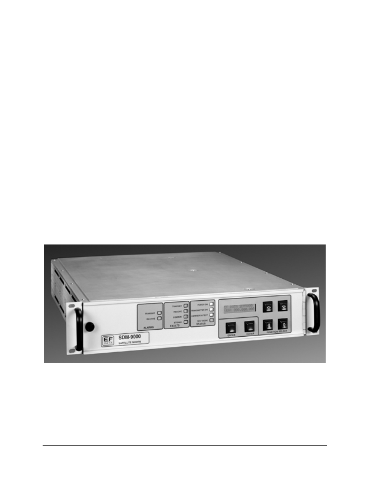
specifications for the SDM-9000 satellite modem, referred to in this manual as
“the modem” (Figure 1-1).
Figure 1-1. SDM-9000
Rev.4 1–1
Page 24
Introduction SDM-9000 Satellite Modem
1.1 Overview
The modem is a high performance, full-duplex, digital-vector modulator/demodulator
that meets the open network requirements of the IESS-308 specifications for
Intermediate Data Rate (IDR). The modem can also be used for any closed network and
satellite communication system applications. Refer to Section 1.1.3 for additional
applications data.
Module types that are compatible with each application are as follows:
Configuration Interface Type FEC Option Options
70/140 MHz Duplex (AC) MIL188/144 with Buffer QPSK
70/140 MHz TX (AC) MIL188/144 with ESC 8PSSK/16QAM
70/140 MHz RX (AC) MIL188/144 with Buffer /RS Digital Video Broadcast
70/140 MHz Duplex (DC ) MIL188/144 with ESC/RS
70/140 MHz TX (DC ) ECL w ith Buffer
70/140 MHz RX (DC) ECL with ESC
ECL with Buffer/RS
PECL with Buffer
PECL with ESC
PECL with Buffer/RS
PECL with ESC/RS
G.703 with Buffer
G.703 with ESC
G.703 Buffer/RS
G.703 with ESC/RS
G.703 with ESC/64 kbit/s
G.703 with ESC/64 kbit/s /RS
50Ω
H/S 10
(DVB)
H/S 10
-7
-7
with DVB
Notes:
1. 75Ω, QPSK, and +5 dBm output are standard with the SDM-9000.
2. The standard Reed-Solomon is in accordance with IESS-308 (IDR).
The modem operates with IF converter equipment operating within a 50 to 180 MHz
band. An internal channel unit, conforming to the IESS-308 specification, provides
overhead designated for Engineering Service Circuits (ESC).
The modem contains:
• Built-in scramblers/descramblers
• Differential encoder/decoder
• Transmit and receive frequency synthesizers
• Multi–rate Forward Error Correction (FEC) convolutional encoder and Viterbi
decoder
1–2 Rev. 4
Page 25

SDM-9000 Satellite Modem Introduction
The modem provides high performance with:
• Narrow occupied bandwidth
• Automatic signal acquisition
• High flexibility
• Extensive online monitoring circuits
The modem interfaces between Single Channel Per Carrier (SCPC) fixed-rate terminal
equipment that operates within the following specifications:
• Data rate of 6.0 to 51.84 Mbit/s
• Symbol rate of 1.7 to 37.5 Ms/s
• Configured to add overhead and framing to the data
The 51.84 Mbit/s data rate is defined by STS-1 (Sonnet specifications).
1.1.1 Nyquist Filter Printed Circuit Boards
The modem features include a Nyquist filter Printed Circuit Board (PCB) for enabling
the user to change data rates at the modulator or demodulator. The modem supports up to
four channels at the following data rate and modulation type combinations:
Data Rates 6.0 to 51.84 Mbit/s Comments
Modulation Types QPSK 1/2 Rate
QPSK 3/4 Rate
QPSK 7/8 Rate
8PSK 2/3 Rate
8PSK 5/6 Rate
16QAM 3/4 Rate
16QAM 7/8 Rate
Optional
Optional
Optional
Optional
Data rate information is automatically recovered from the filter module upon system
power-up or initialization. The installed interface, modulator, and demodulator must be
compatible with the installed filters for proper modem operation. The filters can be
installed in the factory or field.
Refer to Chapter 3 for information about modem configuration.
Rev. 4 1–3
Page 26

Introduction SDM-9000 Satellite Modem
1.1.2 Description
The modem is a complete, self-contained unit in a standard 2 unit (2U) 19”
rack-mountable enclosure weighing approximately 19 lbs. The unit is of modular
construction consisting of five PCB assemblies:
• Modulator
• Demodulator
• Interface
• Display/Monitor & Control (M&C) (front panel)
• Backplane (rear panel)
The backplane PCB is mounted on the chassis assembly and contains receptacles for
three plug-in PCBs:
• Modulator
• Demodulator
• Interface
Test points are located on the front edges of the three PCBs. Figure 1-2 shows the front
view of the modem (without the front panel).
All M&C functions and indicators for operation of the modem are located on the
display/M&C. The chassis also contains a fan (on the rear panel) and a power supply.
Refer to Figure 1-3 for a system block diagram.
Figure 1-2. Modular Construction
1–4 Rev. 4
Page 27
SDM-9000 Satellite Modem Introduction
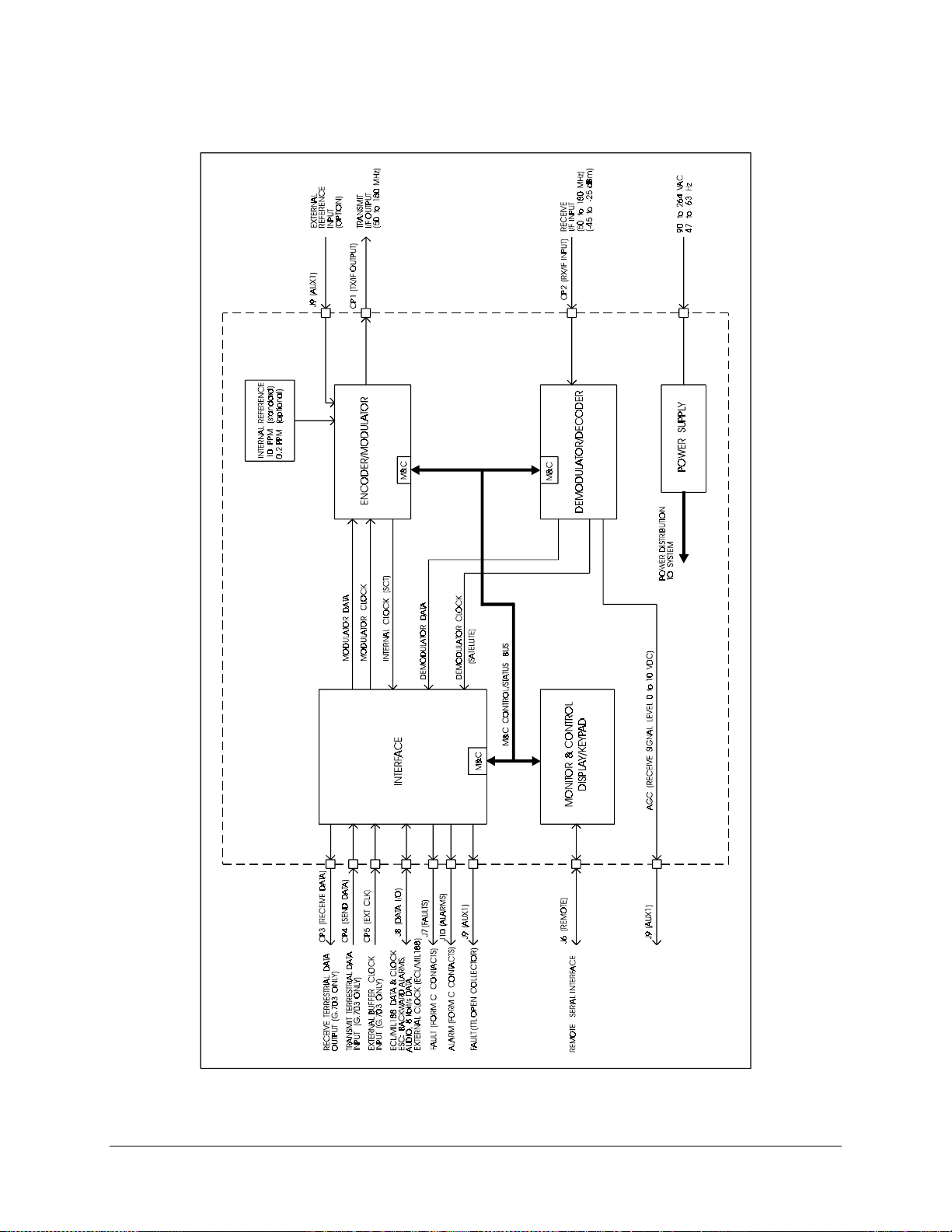
Figure 1-3. SDM-9000 Block Diagram
Rev. 4 1–5
Page 28
Introduction SDM-9000 Satellite Modem
1.1.3 Options
1.1.3.1 Reed-Solomon Codec
The Reed-Solomon Codec works in conjunction with the Viterbi decoder, and includes
additional framing, interleaving, and Codec.
This option can be factory or user installed. Refer to the following table for modem
compatibility requirements.
Interface PCB Type 2 or 3 (or greater)
AS/3971-2
AS/3971-3
Display/M&C PCB AS/2305 Rev. C4 (or greater)
Modulator PCB AS/3969
Demodulator PCB AS/3970
Reed-Solomon Codec PCB AS/4080
Reed-Solomon Daughter
Board (DVB Standard)
AS/4524
Refer to Appendix A for more information.
1.1.3.2 8PSK/16QAM
The 8PSK modulation type is a PSK encoding method for providing a modulated carrier
at 6.0 to 51.84 Mbit/s by pragmatic trellis encoding at 2/3 and 5/6 code rates. This option
is installed at the factory.
The 16QAM is an encoding method for providing a modulated carrier at 6.0 to
51.84 Mbit/s in 3/4 and 7/8 rates.
Interface PCB Type 2 and 3 (or greater)
AS/3971-2
AS/3971-3
Display/M&C PCB AS/2305 Rev. C4 (or greater)
Modulator PCB AS/3969-1, -2, -5, and -6
Demodulator PCB AS/3970-1 and -2
Reed-Solomon Codec PCB AS/4080
Note:
The Reed-Solomon option is required for 8PSK/16QAM operation.
1–6 Rev. 4
Page 29

SDM-9000 Satellite Modem Introduction
1.1.3.3 Direct Broadcast Satellite
As implemented in the SDM-9000, Direct Broadcast Satellite (DBS) mode supports data
rates up to 44.736 Mbit/s using a single FEC channel. Single channel implementation
differs significantly from the International Telecommunications Satellite Organisation
(INTELSAT) specifications (for carriers greater than 10 Mbit/s) for communicating the
data across three channels.
Refer to Appendix A for more information.
Rev. 4 1–7
Page 30
Introduction SDM-9000 Satellite Modem
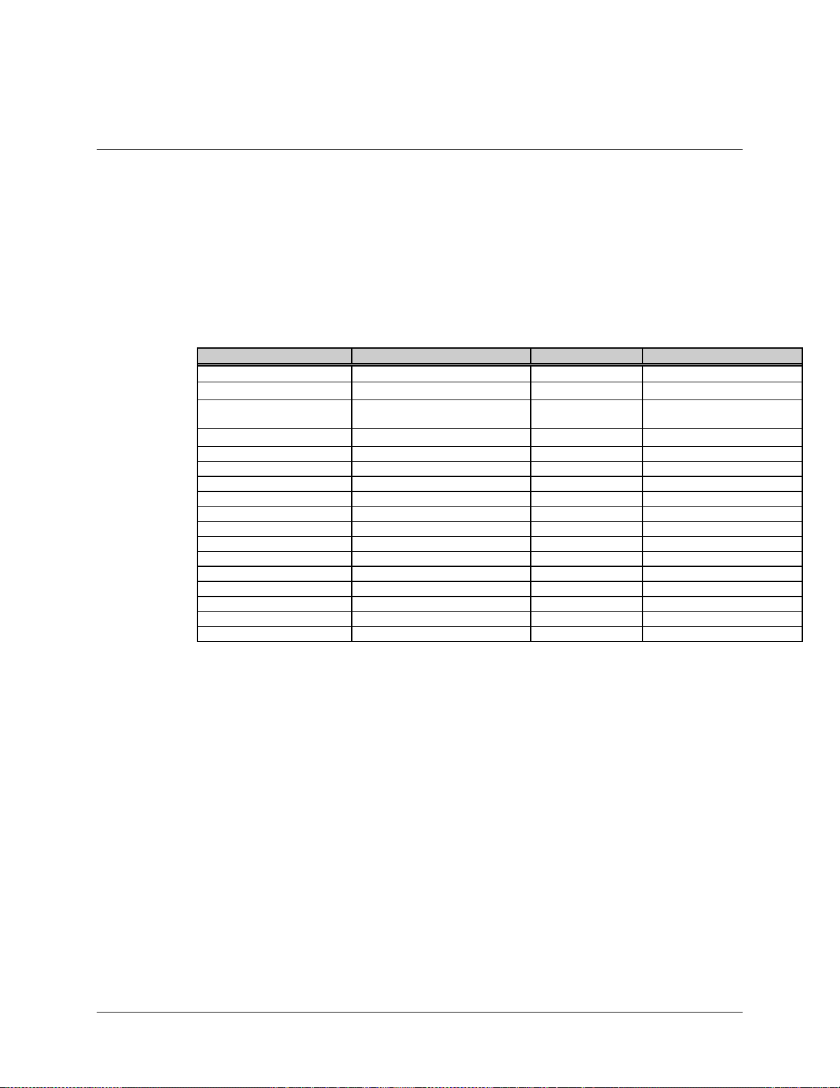
1.2 Modem Assemblies
The following table reflects the possible configurations available for the SDM-9000:
Interface
Configuration Type Chassis P/N Mod Demod.
70/140 MHz Duplex AC 3966-1 X QPSK
70/140 MHz TX AC 3966-1 X
70/140 MHz RX AC 3966-1 X 8PSK/
70/140 MHz Duplex DC 3966-2
70/140 MHz TX DC 3966-2
70/140 MHz RX DC 3966-2
The current main assemblies, options, and alternates for the modem are listed in the table
below:
Type
16QAM
Part
Number
AS/3965 Assy, Top SDM-9000
PL/3966-1 Assy, Chassis, AC CE Mark
PL/3966-2 Assy, Chassis, DC
PL/3978 Motherboard
PL/2305 Display/M onitor & C ontrol No FW/ included
PL/4124-1 Filter, Nyquist TX
PL/4124-2 Filter, Nyquist RX
PL/4109 Supply, Power AC Alternate
PL/4110 Supply, Power AC Preferred
Description Comments
The following table outlines the options available for a specific SDM-9000
configuration:
Output Oscillator Data
Format
50
75
50
75
50
75
50
75
Ω
Ω
Ω
Ω
Ω
Ω
Ω
Ω
Standard QPSK
8PSK
16QAM
Standard QPSK
8PSK
16QAM
Standard QPSK 3969-3 3995-33 3970-3 4401-31
Standard QPSK 3969-4 3995-34 3970-4 4401-32
HI Stability QPSK
8PSK
16QAM
HI Stability QPSK
8PSK
16QAM
HI Stability QPSK 3969-7 3995-37 3970-3 4401-31
HI Stability QPSK 3969-8 3995-38 3970-4 4401-32
Mod P/N RF Mod
P/N
3969-1 3995-33 3970-1 4401-31
3969-2 3995-34 3970-2 4401-32
3969-5 3995-37 3970-1 4401-31
3969-6 3995-38 3970-2 4401-32
Demod
P/N
RF Demod
P/N
1–8 Rev. 4
Page 31

SDM-9000 Satellite Modem Introduction
The following table reflects the relationship of the interface card (MIL-STD-188) with
Reed-Solomon:
ReedInterface Card
(MIL-STD-188)
Condition
Base 4477-13
Buffer 4477-23
Buffer with ESC 4477-33
Buffer with Reed Solomon 4477-23 4080 4524
ESC with Reed-Solomon 4477-33 4080 4524
P/N
Solomon
(IDR STD)
P/N
(DVB STD)
The following table reflects the relationship of the interface card (ECL) with
Reed-Solomon:
Reed Solomon
(IDR STD)
P/N
Condition ECL P/N
Base 4477-11
Buffer 4477-21
ESC 4477-31
Buffer with Reed Solomon 4477-21 4080 4524
ESC with Reed-Solomon 4477-31 4080 4524
Reed
Solomon
P/N
Reed
Solomon
(DVB STD)
P/N
The following table reflects the relationship of the interface card (G.703) with
Reed-Solomon:
Reed Solomon
(IDR STD)
P/N
Condition G.703 P/N
Base 3971-1
Buffer 3971-2
ESC 3971-3
Buffer with Reed Solomon 3971-2 4080 4524
ESC with Reed-Solomon 3971-3 4080 4524
Without Buffer 5618-1
Buffer, 8 Mbit/s 5618-2 4080 4524
ESC, 64kbit/s, 8 Mbit/s 5618-3 4080 4524
Solomon
(DVB STD)
Reed
P/N
Rev. 4 1–9
Page 32

Introduction SDM-9000 Satellite Modem
1.3 Modem Specifications
Table 1-1 lists the operating specifications of the modem.
Table 1-1. SDM-9000 Specifications
General Specifications
Operating Frequency Range 50 to 180 MHz, synthesized in 2.5 kHz steps
Modulation Types
Operating Channel Spacing Less than 0.5 dB degradation operating with 2 adjacent like
BER See Tables 1-2 through 1-4
Baseband Interface:
MIL-STD-188
ECL
G.703
Elastic Buffer 2 to 32 ms, selectable from front panel
Digital Data Rate 6.0 to 51.84 Mbit/s, in 1 bit steps
Scrambling/Descrambling Types
Forward Error Correction:
Viterbi K=7
Reed-Solomon
Pragmatic Trellis
M&C Front panel display (16 character by 2 rows)
Filter Mask Types INTELSAT
ESC IDR or None, field selectable
Loopback Modes
Diagnostic Features
Prime Power 90 to 264 VAC, 47 to 63 Hz,
Size
Weight
• QPSK at 1/2, 3/4, and 7/8 rates
• 8PSK trellis at 2/3 and 5/6 rates (optional)
• 16QAM at 3/4 and 7/8 rates (optional)
channels, each 10 dB higher at 1.3 times the symbol rate
6 to 13 Mbit/s
6 to 51.84 Mbit/s
8.448 Mbit/s
32.064 Mbit/s
34.368 Mbit/s
44.736 Mbit/s
51.840 Mbit/s
• V.35 (per CCITT V.35)
• IDR (per IESS-308)
• EFD (SDM-450 compatible)
Rates:
1/2, 3/4, 7/8
Optional
2/3 and 5/6
• Baseband (near end)
• Interface (near end and far end)
• IF/RF
• IF/RF loopbacks
• Baseband/Interface loopbacks
• Fault monitoring (includes current/stored faults)
• BER monitoring
• Input IF power monitoring
• Buffer fill status monitoring
• Remote control via serial port
200W maximum, fused at 2A
38 to 64 VDC
Physical
3.5” H x 19.0” W x 20.0” D (2 RU) (see Figure 2-1)
19 lbs. (approximate)
1–10 Rev. 4
Page 33

SDM-9000 Satellite Modem Introduction
Environmental
Temperature Range
Humidity
0 to 50°C
0 to 95%, noncondensing
Additional Modulator Specifications
Output Power -20 to +5 dBm, adjustable in 0.1 dB steps
Accuracy
0.5 dB
±
Output Spurious and Harmonics -55 dBc
Output Impedance 75Ω (50Ω optional)
Output Return Loss > 18 dB
Output Frequency Stability
Internal Data Clock Stability
10 PPM (± 0.2 PPM with high stability option)
±
10 PPM internal oscillator
±
0.2 PPM with high stability option
±
Additional Demodulator Specifications
Input Power (Desired Carrier) -45 to -25 dBm
Input Impedance 75Ω (50Ω optional)
Input Return Loss > 18 dB
Carrier Acquisition Range
Clock Acquisition Range
60 kHz maximum
±
100 PPM
±
Remote Control Specifications
Serial Interface RS-232-C or RS-485
Baud Rate 110 to 19200 bit/s
Functions Controlled
• Transmit/Receive frequency
• Transmit power
• Transmitter on/off
• Data rate/modulation
• RF/IF loopback
• Baseband/Interface loopbacks
• Scrambler/Descrambler types
• Scrambler/Descrambler on/off
• Buffer clock TX/RX/INT/EXT
• Receive clock normal/invert
• Differential encoding and decoding
• Transmit and receive overhead type
• IDR backward alarm control on/off
• Reed-Solomon on/off
• Mod and demod spectrum norm/invert
• Sweep width range
• Rev emulation current/functional
Signals Monitored
• Raw error rate
• Corrected BER
• Receive E
b/N0
• Receive signal level
• Receive carrier detect
• Power supply voltages
• Fault status
• Current sweep value
• Stored fault status
Configuration Retention Will maintain current configuration for at least one year
without power
Addressing Programmable to 1 of 255 possibilities; address 0 reserved
for global addressing
Note:
Local control of all remote functions included by push-button entry.
Rev. 4 1–11
Page 34

Introduction SDM-9000 Satellite Modem
1.4 BER Performance Specifications
The bit energy-to-noise ratios (Eb/N0) required to achieve 10-3 to 10
(BERs) are listed in Tables 1-2 through 1-4. The BER performance curves are shown in
the following figures:
Figure Modulation
1-4 QPSK
1-5 QPSK (with Reed-Solomon)
1-6 8PSK (with Reed-Solomon)
1-7 16QAM (with Reed-Solomon)
1.4.1 Viterbi Decoder BER (QPSK)
The Viterbi specifications for the Eb/N0 required to achieve 10-3 to 10
coding configurations are shown in Table 1-2. All values are for operation in QPSK
mode.
Performance measurements are recorded with transmit and receive IF connected
back-to-back through an additive white Gaussian noise channel. Refer to Figure 1-4 for
the Viterbi BER curves.
-10
Bit Error Rates
-8
BER for different
Table 1-2. Viterbi Decoder BER Data
Specification
BER 1/2 Rate 3/4 Rate 7/8 Rate
-3
10
10
10
10
10
10
BER 1/2 Rate 3/4 Rate 7/8 Rate
10
10
10
10
10
10
4.2 dB 5.2 dB 6.4 dB
-4
4.8 dB 6.0 dB 7.2 dB
-5
5.4 dB 6.7 dB 7.9 dB
-6
6.0 dB 7.5 dB 8.6 dB
-7
6.6 dB 8.2 dB 9.2 dB
-8
7.2 dB 8.8 dB 9.9 dB
Typical
-3
3.8 dB 4.8 dB 6.0 dB
-4
4.2 dB 5.5 dB 6.6 dB
-5
4.9 dB 6.1 dB 7.3 dB
-6
5.5 dB 6.7 dB 8.0 dB
-7
6.1 dB 7.6 dB 8.6 dB
-8
6.7 dB 8.2 dB 9.3 dB
1–12 Rev. 4
Page 35

SDM-9000 Satellite Modem Introduction
-2
10
-3
10
-4
10
-5
10
-6
10
BER
-7
10
-8
10
-9
10
-10
10
3.0 4.0 5.0 6.0
Figure 1-4. Viterbi BER Performance Curves (QPSK)
1/2 RATE 3/4 RATE
SPECIFICATIONS
7/8 RATE
7.0 8.0 9.0 10.0 11.0
E
(dB)
b/N0
Rev. 4 1–13
Page 36

Introduction SDM-9000 Satellite Modem
1.4.2 Reed-Solomon Codec BER (QPSK)
The Reed-Solomon specifications for the Eb/N0 required to achieve 10-6 to 10
-10
different configurations are shown in Table 1-3. All values are for QPSK mode
operation. Refer to Figure 1-5 for the Reed-Solomon BER curves.
Table 1-3. Reed-Solomon BER Data
Specification
BER 1/2 Rate 3/4 R ate 7/8 Rate
-6
10
10
10
10
BER 1/2 Rate 3/4 R ate 7/8 Rate
10
10
10
10
4.1 dB 5.6 dB 6.7 dB
-7
4.2 dB 5.8 dB 6.9 dB
-8
4.4 dB 6.0 dB 7.1 dB
-10
4.7 dB 6.4 dB 7.5 dB
Typical
-6
3.5 dB 5.0 dB 6.1 dB
-7
3.6 dB 5.2 dB 6.3 dB
-8
3.8 dB 5.4 dB 6.5 dB
-10
4.1 dB 5.8 dB 6.9 dB
BER for
1–14 Rev. 4
Page 37

SDM-9000 Satellite Modem Introduction
-2
10
-3
10
-4
10
-5
10
-6
10
BER
-7
10
-8
10
-9
10
-10
10
3.0 4.0 5.0 6.0
1/2 RATE 7/8 RATE
Figure 1-5. Reed-Solomon BER Performance Curves (QPSK)
3/4 RATE
SPECIFICATIONS
E
7.0 8.0 9.0 10.0 11.0
(dB)
b/N0
Rev. 4 1–15
Page 38

Introduction SDM-9000 Satellite Modem
1.4.3 8PSK and 16QAM (Viterbi Decoder and Reed-Solomon Codec)
The 8PSK and 16QAM specifications for the Eb/N0 required to achieve 10-6 to 10-9 BER
with the Viterbi decoder and Reed-Solomon Codec are shown in Table 1-4. Refer to
Figures 1-6 (8PSK) and 1-7 (16QAM) for the BER curves with the Reed-Solomon
option.
Table 1-4. 8PSK and 16QAM BER Data
Specification
8PSK 8PSK 16QAM 16QAM
BER 2/3 Rate 5/6 Rate 3/4 Rate 7/8 Rate
-6
10
10
10
10
BER 2/3 Rate 5/6 Rate 3/4 Rate 7/8 Rate
10
10
10
10
6.1 dB 8.2 dB 8.3 dB 9.8 dB
-7
6.4 dB 8.5 dB 8.5 dB 10.0 dB
-8
6.6 dB 8.9 dB 8.7 dB 10.3 dB
-9
6.9 dB 9.3 dB 8.9 dB 10.5 dB
Typical
8PSK 8PSK 16QAM 16QAM
-6
5.6 dB 7.7 dB 7.8 dB 9.4 dB
-7
5.8 dB 7.9 dB 8.1 dB 9.7 dB
-8
6.1 dB 8.4 dB 8.3 dB 9.9 dB
-9
6.3 dB 8.7 dB 8.6 dB 10.2 dB
1–16 Rev. 4
Page 39

SDM-9000 Satellite Modem Introduction
-2
10
-3
10
-4
10
-5
10
-6
10
BER
-7
10
-8
10
-9
10
-10
10
3.0 4.0 5.0 6.0
Figure 1-6. 8PSK BER Performance Curves (with Reed-Solomon)
2/3 RATE
(WITH R-S )
SPECIFICATIONS
5/6 RATE
(WITH R-S )
7.0 8.0 9.0 10.0 11.0
E
(dB)
b/N0
Rev. 4 1–17
Page 40

Introduction SDM-9000 Satellite Modem
-2
10
-3
10
-4
10
-5
10
-6
10
BER
-7
10
-8
10
-9
10
-10
10
4.0 5.0 6.0
Figure 1-7. 16QAM BER Performance Curves (with Reed-Solomon)
3/4 RATE
(WITH R-S )
SPECIFICATIONS
7/8 RATE
(WITH R-S )
7.0 8.0 9.0 10.0 11.0
E
(dB)
b/N0
12.0
1–18 Rev. 4
Page 41

SDM-9000 Satellite Modem Introduction
A typical spectral occupancy curve is shown in Figure 1-8.
Figure 1-8. SDM-9000 Typical Spectral Occupancy
Rev. 4 1–19
Page 42

Introduction SDM-9000 Satellite Modem
This page is intentionally left blank.
1–20 Rev. 4
Page 43

This chapter includes instructions for unpacking and installing the modem, a description
of the external connections, and backward alarm information.
CAUTION
2.1 Unpacking
The modem and manual are packaged in preformed, reusable cardboard cartons
containing foam spacing for maximum shipping protection. The circuit cards are packed
in separate cardboard caddypacks (also packaged within the cardboard carton).
Chapter 2.
INSTALLATION
2
This equipment contains parts and assemblies sensitive to damage by
Electrostatic Discharge (ESD). Use ESD precautionary procedures when
touching, removing, or inserting PCBs.
Do not use any cutting tool that will extend more than 1” into the containe r
and cause damage to the modem.
CAUTION
To remove the modem:
1. Cut the tape at the top of the carton (indicated by OPEN THIS END).
2. Remove the cardboard/foam spacer covering the modem and caddypacks.
3. Remove the modem, caddypacks, manual, and power cord from carton.
4. Save the packing material for storage or reshipment purposes.
5. Inspect the equipment for any possible damage incurred during shipment.
6. Check the equipment against the packing list to ensure the shipment is complete.
7. Refer to Section 2.2 for further system installation instructions.
Rev. 4 2–1
Page 44

Installation SDM-9000 Satellite Modem
2.2 System Options
The standard SDM-9000 with all PCB assemblies installed (Chapter 1) is a full-duplex
QPSK satellite modem. The system can also be configured for TX-only or RX-only
operation.
1. For a TX-only system, the demodulator PCB (AS/3970) should be removed.
• Enter the System Utility menu on the front panel and select Operation mode.
• Enter the menu and select TX-only. This will mask the RX faults and stored
faults in the Faults menu.
2. For RX-only system, the modulator PCB (AS/3969) should be removed.
• Enter the System Utility menu on the front panel and select Operation mode.
• Enter the menu and select RX-only. This will mask the TX faults and stored
faults in the Faults menu.
2–2 Rev. 4
Page 45

SDM-9000 Satellite Modem Installation
2.3 System Installation
Install the modem as follows:
1. Mount the modem chassis in the assigned position of the equipment rack. It is
recommended that the modem be supported by a rack-mounted shelf, or the two
rear rack-mount brackets supplied with the unit.
Note:
For a custom rack installation, refer to the chassis dimensional drawing in
Figure 2-1.
2. Connect the cables to the proper locations on the rear panel. Refer to Section 2.4
for connector pinouts, placement, and functions.
3. Open the front panel and install the three main PCB assemblies (Figure 1-2) as
follows:
a. Install the modulator PCB (AS/3969) in the top slot.
b. Install the interface PCB (AS/3971, AS/4477, or AS/5618) in the middle
slot.
c. Install the demodulator PCB (AS/3970) in the bottom slot.
Note:
The cards are keyed, and will only fit in the proper chassis slot. Verify
the PCBs are properly seated.
4. Before turning on the power switch, verify all interface jumper settings are in
their proper positions (Chapter 3), and become familiar with front panel
operation (Chapter 4).
5. Turn on the power switch (located inside the front panel).
6. Check for the proper TX output signal level and spectrum.
7. Check for the proper RX input signal level and spectrum.
8. If there is any installation problem, refer to Chapter 6 for troubleshooting
assistance.
Rev. 4 2–3
Page 46

Installation SDM-9000 Satellite Modem
Note:
All dimensions are listed in inches.
Figure 2-1. SDM-9000 Dimensional Drawing
2–4 Rev. 4
Page 47

SDM-9000 Satellite Modem Installation
2.4 External Connectors
When a breakout panel is not required, the external modem connections between the
modem and other equipment are made through several rear panel connectors. These
connectors are shown in Figure 2-2, and their locations are listed in Table 2-1. The
connectors are described in the following paragraphs.
When a B141-1 breakout panel is required, refer to the B141-1 Breakout Panel
Installation and Operation Manual for connector information.
Figure 2-2. SDM-9000 Rear Panel View
Note:
In order to meet the European EMC Directive (EN55022, EN50082-1), properly
shielded cables for DATA I/O are required. These cables must be double-shielded from
end to end, ensuring a continuous ground shield.
Table 2-1. Modem Rear Panel Connectors
Name Ref.
Desig.
TX/IF OUTPUT CP1 BNC RF output
RX/IF INPUT CP2 BNC RF input
RECEIVE DATA CP3 BNC RX terrestrial data input
SEND DATA CP4 BNC TX terrestrial data input
EXT CLK CP5 BNC External clock input
REMOTE J6 9-pin D Remote interface
FAULTS J7 9-pin D Form C fault relay contacts
DATA I/O J8 50-pin D Data I/O (ESC)
AUX1 J9 9-pin D TTL faults
ALARMS J10 9-pin D Form C alarm relay contacts
Connector
Type
Function
External reference
AGC output
Rev. 4 2–5
Page 48

Installation SDM-9000 Satellite Modem
2.4.1 TX/IF Output (CP1)
The TX/IF output connection is a BNC connector used for the transmit IF signal. The
output impedance is 75
In normal operation, the output is a modulated carrier with center frequency between 50
and 180 MHz.
(50Ω optional). The output power level is +5 to -20 dBm.
Ω
2.4.2 RX/IF Input (CP2)
The RX/IF input connection is a BNC connector used for the receive IF signal. The input
impedance is 75
should be between -25 and -45 dBm.
The signal frequency of the receive RX/IF input is between 50 and 180 MHz.
(50Ω optional). For normal operation, the desired carrier signal level
Ω
2.4.3 Receive Data (CP3)
The Receive Data connection is a BNC connector used for the terrestrial data output
(G.703 interface only). The output impedance is 75
2.4.4 Send Data (CP4)
The Send Data connection is a BNC connector used for the terrestrial data input (G.703
interface only). The input impedance is 75
2.4.5 External Clock (CP5)
The External Clock connection is a BNC connector used for the external buffer clock
input (Ext Clk). The input impedance is 75
only. The external clock input for ECL/MIL-STD-188 interfaces is provided on the J8
connector.
.
Ω
.
Ω
Ω. This input is used for the G.703 interface
2–6 Rev. 4
Page 49

SDM-9000 Satellite Modem Installation
2.4.6 Remote (J6)
The remote connector is used to interface the M&C functions to a remote location. This
is a Data Circuit Terminating Equipment (DCE) interface that can be either RS-232-C or
RS-485. Refer to Appendix B for remote control operation information.
The remote interface connection is a 9-pin female D connector located on the rear panel
of the modem. Screw locks are provided for mechanical security of the mating connector.
RS-485 RS-232-C
4-Wire Mode 2-Wire Mode
Pin # Name Name Pin # Name
1GND GND 1
2 2 RD (RX)
33TD (TX)
4 +TX +RX/TX 4
5 -TX -RX/TX 5 GND
66DSR
77RTS
8 +RX +RX/TX 8 CTS
9-RX-RX/TX 9
Rev. 4 2–7
Page 50

Installation SDM-9000 Satellite Modem
2.4.7 Fault (J7)
The fault connector is used to provide Form C contact closures for fault reporting. The
three Form C summary fault contacts are:
• Transmit faults
• Receive faults
• Common equipment faults
Refer to Chapter 4 for a discussion of faults monitored. To obtain a system summary
fault, connect all the Form C contacts in parallel
The fault interface connection is a 9-pin female D connector located on the rear panel of
the modem. Screw locks are provided for mechanical security on the mating connector.
Signal Function Name Pin #
Common equipment is OK NO 1
Common COM 2
Common equipment is faulted NC 3
Transmit is OK NO 4
Common COM 5
Transmit is faulted NC 6
Receive is OK NO 7
Common COM 8
Receive is faulted NC 9
Note:
A connection between the common (COM) and normally open (NO) contacts
indicates no fault.
2–8 Rev. 4
Page 51

SDM-9000 Satellite Modem Installation
2.4.8 DATA I/O (ESC) Interface (J8)
The DATA I/O (ESC) connection is a 50-pin female D connector located on the rear
panel of the modem. Screw locks are provided for mechanical security of the mating
connector.
The J8 connector is used to interface data input/output and ESC signals to and from the
modem. The configuration of J8 depends on the following interface types:
• G.703
•ECL
•PECL
• MIL-STD-188
The DATA I/O pinout will be different for each of the interface configurations. The
interface pinouts are listed in the following sections. Refer to the following Notes for
additional data applying to each condition.
Notes:
1. Backward alarm relay contacts named for normal no-fault condition
(BWOx–C connected to BWOx–NC if no fault).
2. Backward alarm inputs must be grounded or pulled logic low to clear alarm.
3. Signals MF, DF, and DMA are open-collector high-impedance, if faulted. MF
and DF are used by M:N protection switch, if used in redundant system.
4. Relay contacts DF–C and DF–NO named for faulted condition (DF–C connected
to DF–NO unless Demod fault).
Rev. 4 2–9
Page 52

Installation SDM-9000 Satellite Modem
2.4.8.1 G.703 (IDR) Interface (J8) (Audio Mode)
Signal Function Name Pin #
Ground GND 1, 2
8 kbit/s TX data input (RS-422) TXD–A 37
TXD–B 38
8 kHz TX clock output (RS-422) TXC–A 21
TXC–B 22
1 kHz TX octet input (RS-422) TXO–A 4
TXO–B 5
8 kbit/s RX data output (RS-422) RXD–A
RXD–B
8 kHz RX clock output (RS-422) RXC–A 23
RXC–B 24
1 kHz RX octet output (RS-422) RXO–A 6
RXO–B 7
ADPCM 1 audio input A1I–A 45
A1I–B 29
ADPCM 1 audio output A1O–A 46
A1O–B 30
ADPCM 2 audio input A2I–A 47
A2I–B 31
ADPCM 2 audio output A2O–A 48
A2O–B 32
Backward alarm 1 output BWO1–C 8
BWO1–NC 25
BWO1–NO 41
Backward alarm 2 output BWO2–C 9
BWO2–NC 26
BWO2–NO 42
Backward alarm 3 output BWO3–C 10
BWO3–NC 27
BWO3–NO 43
Backward alarm 4 output BWO4–C 11
BWO4–NC 28
BWO4–NO 44
Backward alarm 1 input BWI1 12
Backward alarm 2 input BWI2 13
Backward alarm 3 input BWI3 14
Backward alarm 4 input BWI4 15
Modulator fault (TTL) MF 49
Demodulator fault (TTL) DF 33
Deferred maintenance alarm DMA 17
Demodulator fault relay DF–C 16
DF–NO 50
AGC output
AGC–OUT 3
(receive input, if level)
39
40
(Note 1)
(Note 1)
(Note 1)
(Note 1)
(Note 2)
(Note 2)
(Note 2)
(Note 2)
(Note 3)
(Note 3)
(Note 3)
(Note 4)
2–10 Rev. 4
Page 53

SDM-9000 Satellite Modem Installation
2.4.8.2 G.703 (IDR) Interface (J8) (64 kbit/s Mode)
Signal Function Name Pin #
Ground GND 1, 2
8 kbit/s TX data input (RS-422) TXD–A 37
TXD–B 38
8 kHz TX clock output (RS-422) TXC–A 21
TXC–B 22
1 kHz TX octet input (RS-422) TXO–A 4
TXO–B 5
8 kbit/s RX data output (RS-422) RXD–A 39
RXD–B 40
8 kHz RX clock output (RS-422) RXC–A 23
RXC–B 24
1 kHz RX octet output (RS-422) RXO–A 6
RXO–B 7
64 kbit/s send data input (RS-422) E-SD-A
E-SD-B
64 kHz receive timing out
(RS-422)
E-RT-A
E-RT-B
64 kHz send timing out (RS-422) E-ST-A 47
E-ST-B 31
64 kbit/s receive data out (RS-422) E-RD-A
E-RD-B
Backward alarm 1 output BWO1–C 8
BWO1–NC 25
BWO1–NO 41
Backward alarm 2 output BWO2–C 9
BWO2–NC 26
BWO2–NO 42
Backward alarm 3 output BWO3–C 10
BWO3–NC 27
BWO3–NO 43
Backward alarm 4 output BWO4–C 11
BWO4–NC 28
BWO4–NO 44
Backward alarm 1 input BWI1 12
Backward alarm 2 input BWI2 13
Backward alarm 3 input BWI3 14
Backward alarm 4 input BWI4 15
Modulator fault (TTL) MF 49
Demodulator fault (TTL) D F 33
Deferred maintenance alarm DMA 17
Demodulator fault relay DF–C
DF–NO
AGC output
AGC–OUT 3
(receive input, if level)
45
29
46
30
48
32
16
50
(Note 1)
(Note 1)
(Note 1
(Note 1)
(Note 2)
(Note 2)
(Note 2)
(Note 2)
(Note 3)
(Note 3)
(Note 3)
(Note 4)
)
Rev. 4 2–11
Page 54

Installation SDM-9000 Satellite Modem
2.4.8.3 ECL Interface (J8)
Signal Function Name Pin #
Ground GND 1, 2
Send data input TXD–A (ECL-) 37
TXD–B (ECL+) 38
Terrestrial timing input (TT) TXO–A (ECL-) 4
TXO–B (ECL+) 5
SYNC TX frame input (TX SY N C) SD–A (ECL-) 34
SD–B (ECL+) 18
Send timing output (ST) TXC–A (ECL-) 21
TXC–B (ECL+) 22
Receive data output (RD) RXD–A (ECL-) 39
RXD–B (ECL+) 40
Receive timing output (RT) RX C–A (EC L-) 23
RXC–B (ECL+) 24
SYNC RX frame output (RX SYNC) RD–A (ECL-) 36
RD–B (ECL+) 20
External clock input (EXC) EXC- (ECL-) 35
EXC+ (ECL+) 19
ADPCM 1 audio input A1I–A 45
A1I–B 29
ADPCM 1 audio output A1O–A 46
A1O–B 30
ADPCM 2 audio input A2I–A 47
A2I–B 31
ADPCM 2 audio output A2O–A 48
A2O–B 32
Backward alarm 1 output BWO1–C 8
BWO1–NC 25
BWO1–NO 41
Backward alarm 2 output BWO2–C 9
BWO2–NC 26
BWO2–NO 42
Backward alarm 3 output BWO3–C 10
BWO3–NC 27
BWO3–NO 43
Backward alarm 4 output BWO4–C 11
BWO4–NC 28
BWO4–NO 44
Backward alarm 1 input BWI1 12
Backward alarm 2 input BWI2 13
Backward alarm 3 input BWI3 14
Backward alarm 4 input BWI4 15
Modulator fault (TTL) MF 49
Demodulator fault (TTL) DF 33
Deferred maintenance Alarm DMA 17
Demodulator fault relay DF–C 16
DF–NO 50
AGC output (receive input, if level) AGC–OUT 3
(Note 1
(Note 1
(Note 1)
(Note 1)
(Note 2)
(Note 2
(Note 2)
(Note 2)
(Note 3)
(Note 3
(Note 3)
(Note 4
)
)
)
)
)
2–12 Rev. 4
Page 55

SDM-9000 Satellite Modem Installation
2.4.8.4 MIL-STD-188 Interface (J8)
Signal Function Name Pin #
Ground GND 1, 2
Send data input TXD–A 37
TXD–B 38
Terrestrial timing input (TT) TXO–A 4
TXO–B 5
Request to send input (RTS) SD–A 34
SD–B 18
Send timing output (ST) TXC–A 21
TXC–B 22
Receive data output (RD) RXD–A 39
RXD–B 40
Receive timing output (RT) RXC–A 23
RXC–B 24
Data mode output (DM/DSR) RD–A 36
RD–B 20
External clock input (EXC) EXC- 35
EXC+ 19
Receiver ready output (RR/RLSD) RXO–A 6
RXO–B 7
ADPCM 1 audio input A1I–A 45
A1I–B 29
ADPCM 1 audio output A1O–A 46
A1O–B 30
ADPCM 2 audio input A2I–A 47
A2I–B 31
ADPCM 2 audio output A2O–A 48
A2O–B 32
Backward alarm 1 output BWO1–C 8
BWO1–NC 25
BWO1–NO 41
Backward alarm 2 output BWO2–C 9
BWO2–NC 26
BWO2–NO 42
Backward alarm 3 output BWO3–C 10
BWO3–NC 27
BWO3–NO 43
Backward alarm 4 output BWO4–C 11
BWO4–NC 28
BWO4–NO 44
Backward alarm 1 input BWI1 12
Backward alarm 2 input BWI2 13
Backward alarm 3 input BWI3 14
Backward alarm 4 input BWI4 15
Modulator fault (TTL) MF 49
Demodulator fault (TTL) DF 33
Deferred maintenance alarm DMA 17
Demodulator fault relay DF–C 16
DF–NO 50
AGC output (receive input, if level) AGC–OUT 3
(Note 1)
(Note 1)
(Note 1)
(Note 1)
(Note 2)
(Note 2)
(Note 2)
(Note 2)
(Note 3)
(Note 3)
(Note 3)
(Note 4)
Rev. 4 2–13
Page 56

Installation SDM-9000 Satellite Modem
2.4.9 AUX 1 (J9)
The Auxiliary 1 (AUX 1) connector provides:
• TTL faults
• External high stability reference
• AGC output voltage
The faults are open collector levels to indicate a modulator or demodulator failure. A
logic 1 indicates the faulted condition. The signals are primarily used in operating a
protection switch.
The external high stability reference clock input is 5, 10, or 20 MHz.
AGC-OUT is the voltage for a receive signal level between -25 and -50 dBm.
The AUX 1 connection is a 9-pin female D connector located on the rear panel of the
modem. Screw locks are provided for mechanical security on the mating connector.
Signal Function Name Pin #
Ground GND 5, 6, 8
External reference EXT –REF 2
Transmit fault MDTTLFLT 4
Receive fault DMTTLFLT 7
AGC output
(Receive input, IF level)
AGC–OUT 1
2–14 Rev. 4
Page 57

SDM-9000 Satellite Modem Installation
2.4.10 Alarms (J10)
The alarms connector is used to provide three Form C contact closures for alarm
reporting, as follows:
• Alarm 1 = Not used
• Alarm 2 = TX
• Alarm 3 = RX
The two Form C summary fault contacts currently used are:
• Transmit alarm (Alarm 2)
• Receive alarm (Alarm 3)
Refer to Chapter 4 for a discussion of alarms monitored. To obtain a system summary
alarm, connect all the Form C contacts in parallel.
The alarms connection is a 9-pin female D connector located on the rear panel of the
modem. Screw locks are provided for mechanical security on the mating connector.
Signal Function Name Pin #
Alarm 1 is OK NO 1
Common COM 2
Alarm 1 is faulted NC 3
Alarm 2 is OK NO 4
Common COM 5
Alarm 2 is faulted NC 6
Alarm 3 is OK NO 7
Common COM 8
Alarm 3 is faulted NC 9
Note:
A connection between the common (COM) and normally open (NO) contacts
indicates no alarm.
Rev. 4 2–15
Page 58

Installation SDM-9000 Satellite Modem
2.4.11 AC Power
The AC power is supplied to the modem by a standard detachable, non-locking, 3-prong
power cord (IEC plug). Normal input voltage is 90 to 264 VAC, 47 to 63 Hz. The power
supply will automatically switch between ranges. Maximum power consumption is less
than 200W.
2.4.12 DC Power
The DC power is supplied to the modem by a standard detachable, non-locking, 3-prong
power cord (IEC plug). Normal input voltage is 38 to 64 VDC.
2.4.13 Ground (GND)
A #10-32 stud on the rear panel of the modem is used for connecting a common chassis
ground between all equipment.
Note:
The safety ground is provided through the AC power connector.
2–16 Rev. 4
Page 59

This chapter describes the hardware and software configuration of the modem.
Note:
3.1 Display/M&C
The Display/M&C PCB (AS/2305) is located on the front panel of the modem.
Figure 3-1 shows the Display/M&C card and the jumper locations. The jumper settings
are listed in Table 3-1.
All modem functions can be remotely controlled and monitored via an RS-485/
RS-232-C communications link. The 2- or 4-wire, half-duplex RS-485 interface makes it
possible to operate 1 to 255 modems on a common communications link. The RS-232-C
interface is used to communicate with a single modem.
Chapter 3.
CONFIGURATION
3
All jumper settings are described in their appropriate tables.
The M&C module must be hardware configured to one of the two interfaces as listed in
Table 3-1.
Rev.4 3–1
Page 60

Configuration SDM-9000 Satellite Modem
ASSEMBLY NUMBER AND
SERIAL NUMBER
JP2JP3JP1 JP5
Figure 3-1. Display/M&C PCB
Table 3-1. Display/M&C PCB Jumper Settings
Jumper Position Function
JP1 1 to 2
3 to 4
5 to 6
7 to 8
(
JP2
See Note
) 1 to 2
2 to 3
JP3
(
See Note
)
1 to 2
2 to 3
JP5 1 to 2
2 to 3
JP9 and JP10 32K
64K
128K
256K
256K
Note:
Pins JP2 and JP3 must be in the 4-wire position for RS-232-C.
RS-485 Remote
RS-485 Remote
RS-232-C Remote
RS-232-C Remote
4-Wire
2-Wire
4-Wire
2-Wire
RS-485 Remote
RS-232-C Remote
27C256 EEPROM at U17
27C512 EEPROM at U17
27C010 EEPROM at U17
27C020 EEPROM at U17
27C040 EEPROM at U17
JP9 JP10
RS-485 Configuration Install two jumpers (shunts) at the RS-485 positions of JP1, and
install one jumper at the RS-485 position of JP5.
For 2- or 4-wire operation, position jumpers at JP2 and JP3 to the
designated positions.
RS-232-C Configuration Install two jumpers (shunts) at the RS-232-C positions of JP1, and
install one jumper at the RS-232-C position of JP5.
Install jumpers at JP2 and JP3 for 4-wire operation.
3–2 Rev. 4
Page 61

SDM-9000 Satellite Modem Configuration
3.2 Modulator
The modulator PCB (AS/3969) is located in the top slot of the modem chassis. The
jumper settings are listed in Table 3-2. Figure 3-2 shows the modulator card and the
jumper locations.
Table 3-2. Modulator PCB Jumper Settings
Jumper Position Function
J7 1 to 2
2 to 3
J9
(EEPROM size select)
Note:
The modulator PCB jumpers in Table 3-2 are factory set.
1 to 2
2 to 3
Normal, processor control
Output forced ON, test mode
27C512 (64K EEPROM)
27C256 (32K EEPROM)
Figure 3-2. Modulator PCB (AS/3969)
Rev.4 3–3
Page 62

Configuration SDM-9000 Satellite Modem
3.3 Demodulator
The demodulator PCB (AS/3970) is located in the bottom slot of the modem chassis. The
jumper settings are listed in Table 3-3. Figure 3-3 shows the demodulator card and the
location of jumper JP5.
Table 3-3. Demodulator PCB Jumper Settings
Jumper Position Function
JP5 (EEPROM size select) 1 to 2
2 to 3
Note:
The demodulator PCB jumpers in Table 3-3 are factory set.
27C256 (32K EEPROM)
27C512 (64K EEPROM)
Figure 3-3. Demodulator PCB (AS/3970)
3–4 Rev. 4
Page 63

SDM-9000 Satellite Modem Configuration
3.4 Interface
The interface PCB (AS/3971, AS/4477, or AS/5618) is located in the middle slot of the
modem chassis. The three interface configurations are:
AS/3971 G.703
AS/4477 ECL/MIL-STD-188-144
AS/5618-3 G.703 with 64 kbit/s ESC
Note:
The AS/5618-3 G.703 interface assembly supports one 64 kbit/s data channel or
two 32 kbit/s audio channels (per IESS-308, Rev. 8A). The modem can provide
independent transmit (TX) and receive (RX) of audio or digital 64 kbit/s data. This
allows four possible applications:
• TX and RX: one 64 kbit/s data channel
• TX and RX: two 32 kbit/s audio channels
• TX: one 64 kbit/s data channel while RX: two 32 kbit/s audio channels
• TX: two 32 kbit/s audio channels while RX: one 64 kbit/s data channel
The jumper settings are listed in Table 3-4. Figure 3-4 (AS/3971) and Figure 3-5
(AS/4477) show the interface cards and the locations of jumper JP1.
See Table 3-4 for the appropriate jumper settings for a particular application.
Table 3-4. Interface Configuration Jumper Settings
AS/3971 Interface Only
Jumper Position Function
JP1 (EEPROM size select) 1 to 2
2 to 3
AS/5618-3 G.703 Interface Only
Channel Jumper Position Function
TX JP7
(Jumper block)
RX JP6
(Jumper block)
Note:
See options, Appendix A for additional timing information.
1 to 2
2 to 3
1 to 2
2 to 3
27C256 (32K EEPROM)
27C512 (64K EEPROM)
64 kbit/s
Audio
64 kbit/s
Audio
Rev.4 3–5
Page 64

Configuration SDM-9000 Satellite Modem
JP1
Figure 3-4. Interface PCB (AS/3971)
3–6 Rev. 4
Page 65

SDM-9000 Satellite Modem Configuration
Figure 3-5. Interface PCB (AS/4477)
Rev.4 3–7
Page 66

Configuration SDM-9000 Satellite Modem
JP7
JP6
JP1
Figure 3-6. Interface PCB (AS/5618)
3–8 Rev. 4
Page 67

SDM-9000 Satellite Modem Configuration
3.5 Nyquist Filter Configuration
The Nyquist filter (AS/4124) is a 4.5” x 5.0” daughter card that is located on the
modulator and demodulator PCBs. The filters are capable of supporting four data/code
rate and modulation type combinations per card. There is one TX card and one RX card:
Type Part Number Used with
TX PCB AS/4124-1 Baseband Modulator PCB (AS/3969)
RX PCB AS/4124-2 Baseband Demodulator PCB (AS/3970)
The filters include a factory programmable device that contains:
• Data Rates
• Coding Rates
• Symbol Rates
• Options
This information is programmed into the filter PCB at calibration time. A label indicates
the symbol rates of the populated filters. For example, a Nyquist filter may be required
with four symbol rates as follows:
• 21.376 MHz
• 22.912 MHz
• 29.824 MHz
• 34.560 MHz
Configuration information is recovered from the filter PCBs during system power-up and
initialization. The filter configuration information is available to the user. Refer to
Chapter 4 for the Configuration Modulator, Configuration Demodulator, and Utility
menus.
Rev.4 3–9
Page 68

Configuration SDM-9000 Satellite Modem
3.5.1 Compatibility
For proper modem operation, the installed interface, modulator, and demodulator must
be compatible with the installed filters. Refer to the following table for baseband
interface data rates.
Interface Type Data Rates
G.703 8.448 Mbit/s
32.064 Mbit/s
34.368 Mbit/s
44.736 Mbit/s
51.840 Mbit/s
ECL/PECL 6.0 to 52.0 Mbit/s, in 1 bit/s steps
MIL-STD-188 6.0 to 13.0 Mbit/s, in 1 bit/s steps
3.5.2 Installation
Installation instructions for the field-installed Nyquist filters (AS/4124) include:
• Unpacking/initial inspection
• Tools required
• Installation procedure
3.5.2.1 Unpacking Instructions
This equipment contains parts and assemblies sensitive to damage by ESD.
Use ESD precautionary procedures when touching, removing, or inserting
CAUTION
PCBs.
1. Remove the Nyquist filter PCB and mounting hardware from the cardboard
caddypack and anti-static material.
2. Check packing list to ensure the shipment is complete.
3. Inspect the Nyquist filter PCB for any shipping damage. Ensure all ICs are
seated properly.
3–10 Rev. 4
Page 69

SDM-9000 Satellite Modem Configuration
3.5.2.2 Tools Required
The following tool is required to accomplish the task of this section:
Tool Description
Driver, Nut 1/4-inch
3.5.2.3 Installation Procedure
Note:
The Nyquist filter PCB is field-replaceable to enable the user to install optional
data rates.
1. Install the Nyquist filter PCB as a daughter card on the modulator or
demodulator PCB as follows:
Type Part Number Used with
TX PCB AS/4124-1 Baseband Modulator PCB (AS/3969)
RX PCB AS/4124-2 Baseband Demodulator PCB (AS/3970)
a. Ensure that each filter has three 10-pin connectors for I/O and power.
b. Mount the card on the four standoffs with a 1/4” hex nut on each standoff to
secure the PCB. Tighten each nut using the 1/4” nut driver.
2. Refer to Figure 3-7 for connector locations.
3.5.2.3.1 Nyquist Filter Removal
1. Remove the TX filter (AS/4124-1) or RX filter (AS/4124-2) as follows:
a. Open the modem front door and turn off the power.
b. Remove the modulator or demodulator PCB from the modem and place on a
static-free work area.
c. Remove the four 1/4” hex nuts that secure the filter card (AS/4124-X) using
the 1/4” nut driver.
Note:
Do not remove the screws and standoffs from the modulator or
demodulator. Remove the four hex nuts only.
2. Carefully unplug the filter card from the modulator or demodulator connectors.
Rev.4 3–11
Page 70

Configuration SDM-9000 Satellite Modem
Figure 3-7. Nyquist Filter Installation
3–12 Rev. 4
Page 71

SDM-9000 Satellite Modem Configuration
3.5.2.3.2 Nyquist Filter Replacement
1. Replace the TX filter (AS/4124-1) or RX filter (AS/4124-2) as follows:
a. Remove the TX/RX filter card (AS/4124) in accordance with
Section 3.5.2.3.1.
b. Carefully install the TX/RX filter card on the three 10-pin connectors.
Note:
The TX/RX filter cards are keyed for easy installation.
TX Filter
Connectors
Filter Modulator Filter Demodulator
JP1 JP1 JP1 P1
JP2 JP2 JP2 P3
JP3 JP4 JP3 P2
RX Filter
Connectors
Ensure the connector pins are not bent during installation.
CAUTION
c. Install the four 1/4” hex nuts to the standoffs, and tighten using the 1/4” nut
driver.
2. Install the modulator or demodulator in the modem.
Rev.4 3–13
Page 72

Configuration SDM-9000 Satellite Modem
3.6 Software Configuration
This section consists of the following software information:
• Revision emulation feature
• Programming the remote baud rates/addresses
• Modem defaults
3.6.1 Revision Emulation
The modem includes a revision emulation feature that allows the user to program an
emulation mode of a previous functional revision. This feature is accessed through the
Utility Modem Type menu (refer to Chapter 4). The user can emulate Version 1.1.1
through the current version by selecting a functional number at the Rev. Emulation menu
(refer to Table 3-5).
Table 3-5. SDM-9000 Revision Emulation
Functional # Software
Version
1 1.1.1 4100-1- Original version
2 2.1.1 4100-1A Software changes
3 3.1.1 4100-1B Software changes
3 3.1.2 4100-1C Correctional Setting
4 4.1.1 4100-1D Software changes
5 5.1.1 4100-1E Software changes
6 6.1.1 4100-1F Software changes
Firmware # Description of Change
Notes:
1. Programming a functional number (1 through X) eliminates all changes
(disables new features/options) for the later version numbers. For example,
functional number 3 may eliminate some features/options for Version 4.1.1
or greater.
2. Programming Current Version (default) allows all features and options to
operate (if installed).
3. The user must manually program the functional version on a cold-start
(default is Current Version).
4. Revision emulation will not affect some user interface changes that do not
affect direct operation of the modem. For example: Configuration
Save/Recall; cosmetic changes; Test Mode screen in the Utility System
menu; all Factory Setup modes, and so forth.
3–14 Rev. 4
Page 73

SDM-9000 Satellite Modem Configuration
3.6.2 Remote Interface Specification
Refer to Appendix B for remote control operation information.
3.6.2.1 Remote Baud Rate
The remote communications baud rate and parity are programmed by the front panel
control in the Utility System menu (refer to Chapter 4). The programmed baud rate and
parity are maintained indefinitely by use of the EEPROM on the M&C module. The
parity bits can be set to EVEN, ODD, or NONE (with 8 data bits). The available baud
rates (bit/s) are listed below:
• 110
• 150
• 300
• 600
• 1200
• 2400
• 4800
• 9600
• 19200
3.6.2.2 Remote Address
To communicate with the established remote communications protocol, each modem
must be configured for one address between 1 and 255. Address 0 is reserved as a global
address that simultaneously addresses all devices on a given communications link. Each
modem on a common remote communications link (RS-485) must have a distinct
address.
The addresses are programmed by front panel control in the Utility System menu and
maintained in EEPROM.
Rev.4 3–15
Page 74

Configuration SDM-9000 Satellite Modem
3.6.3 Modem Defaults
With certain exceptions, the M&C default settings are loaded into the modem after a
hard reset (refer to Chapter 4). The defaults are listed in Table 3-6.
In the case of the exceptions, the settings last saved are retained. Exceptions include the
following:
• Address
• Parity
• Baud Rate
• Ext AGC: Minimum Pwr
• Ext AGC: Maximum Pwr
• Display Contrast
Table 3-6. Modem Defaults
Modulator Defaults Demodulator Defaults
Data Rate
IF Frequency 70 MHz IF Frequency 70 MHz
IF Output OFF Differential Decoder ON
Mod Power Offset 0 dB IF Loopback OFF
TX Power Level 0.0 dBm RF Loopback OFF
Differential Encoder ON BER Threshold NONE
Carrier Mode Normal (OFF) Demod Spectrum Normal
Mod Spectrum Normal
Buffer Clock Source RX Satellite Descrambler ON
TX Clock Phase Normal Buffer Size 12 ms
RX Clock Phase Normal Service Channel T X 1 -5 dBm
Ext-Ref Freq. 5000.000 kHz Service Channel TX2 -5 dBm
B-Band Loopback OFF Service Channel RX1 -5 dBm
Intrfc Loopback OFF Service Channel RX2 -5 dBm
TX Coding Format AMI Loop Timing OFF
RX Coding Format AMI TX Overhead Type NONE
TX 2047 Pattern OFF RX Overhead Ty pe NONE
RX 2047 Pattern OFF TX Data Phase Normal
TX Data Fault NONE RX Data Phase Normal
RX Data Fault NONE IDR B/W Alarm Control ON
Descrambler Type IDR Scrambler ON
Scrambler Type IDR Scrambler Defaults ON
Operation Mode Duplex Remote Address (See Note) 1
Baud Rate (See Note) 9600 Time 12:00 AM
Parity (See Note) EVEN Date 11/21/94
Ext AGC: Min Pwr
(
See Note
(See Note)
)
TX Rate A Data Rate
Interface Defaults
System Defaults
10.0V Ext AGC: Max Pwr 0.0V
(See Note)
RX Rate A
Note:
All code rate/data rate information is read from the modulator/demodulator filter
boards on power-up. If a board is missing or the filters were not installed per order,
“N/A” (Not Applicable) will be displayed on the front panel.
3–16 Rev. 4
Page 75
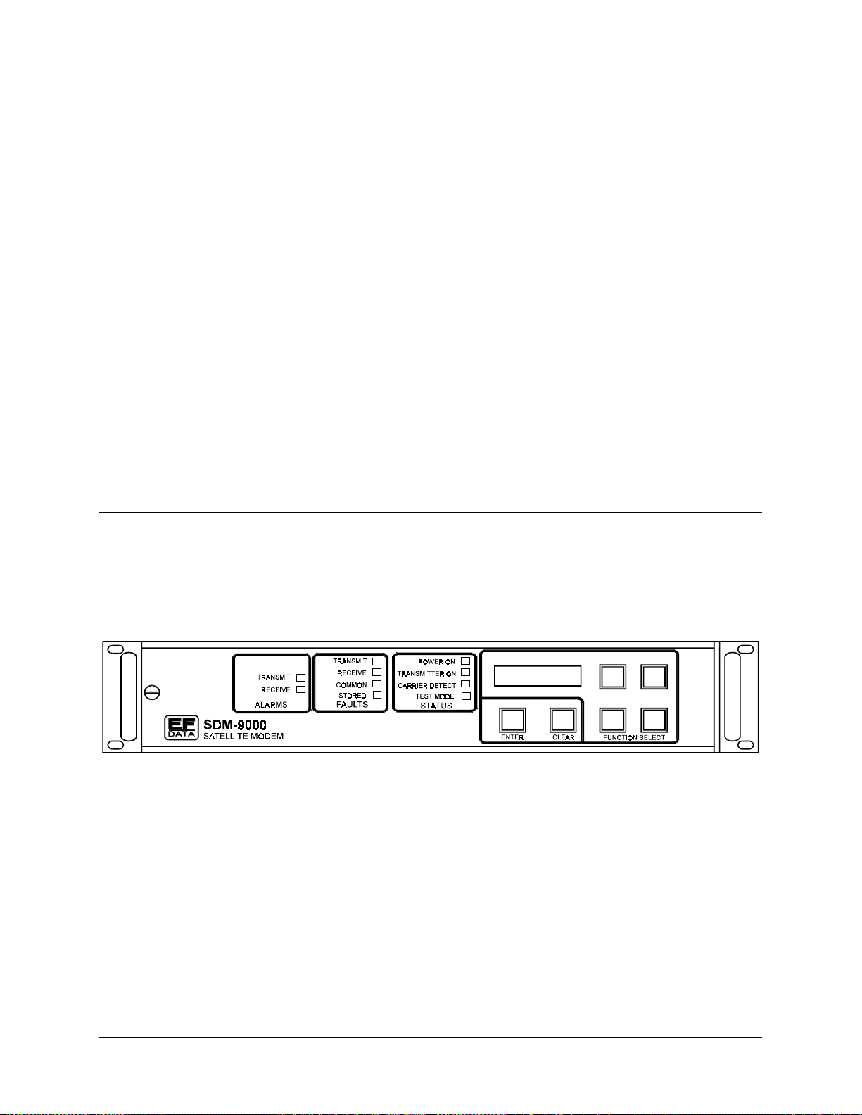
This chapter includes operational information for the front panel and the menu system.
4.1 Front Panel
The modem front panel (Figure 4-1) enables the user to control modem configuration
parameters and display the modem status.
Chapter 4.
OPERATION
4
Figure 4-1. SDM-9000 Front Panel View
The major front panel features are:
• 32-character, 2-line LCD display
• 6-button keypad for providing sophisticated functions
• 10 LEDs to provide overall status at a glance
Rev. 4 4–1
Page 76

Operation SDM-9000 Satellite Modem
All functions are accessible at the front panel by entering one of five pre-defined
Function Select categories or levels:
• Configuration
• Monitor
• Faults/Alarms
• Stored Faults/Alarms
• Utility
4.1.1 LED Indicators
General modem summary fault information, status, and alarms are indicated by the
10 LEDs on the front panel. The LEDs, when lit, indicate the following information:
LED Color Description
Faults
TX Red A fault condition exists in the T X chain.
RX Red A fault condition exists in the RX chain.
Common Red A common equipment fault condition exists.
Stored Yellow A fault has been logged and stored. The fault may be active.
Status
Power ON Green Power is applied to the modem.
TX ON Green TX is currently on. This indicator reflects the actual condition of
the TX, as opposed to the programmed condition.
Carrier Detect Green Decoder is locked.
Test Mode Yellow Flashes when the modem is in a test configuration. The test
mode status can be identified in the Utility System menu in
Figure 4-14.
Alarms
TX Yellow A TX function is in an alarm condition.
RX Yellow AN RX function is in an alarm condition.
4–2 Rev. 4
Page 77

SDM-9000 Satellite Modem Operation
4.1.2 Front Panel Controls
The modem is locally operated by using the front panel keypad (Figure 4-1). The keypad
consists of six keys. Each key provides one or more logical functions:
Key Function
[ENTER] [ENTER] is used to select a displayed function or to ex ecute a modem
configuration change.
[CLEAR] [CLEAR] is used to back out of a selection or to cancel a configuration change
which has not been executed using [ENTER]. Pressing [CLEAR ] generally
returns the display to the previous selection.
[←] and [→]
[↑] and [↓]
The modem responds by beeping whenever a key is pressed:
• A single beep indicates a valid entry and the appropriate action was taken.
• A double beep indicates an invalid entry or a parameter is not available.
These keys are used to move to the next selection or to move the cursor for
certain functions.
These keys are used primarily to change configuration data (numbers), but are
also used at times to move from one section to another.
The modem front panel control uses a tree-structured menu system (Figures 4-2 through
4-16) to access and execute all functions. The base level of this structure is the sign-on
message that is displayed on the front panel when the modem power is turned on:
• Line 1 of the sign-on message is the modem model number (SDM-9000).
• Line 2 is the version number of the firmware implemented in the modem.
The main level of the menu system is Function Select. This may be accessed from the
base level by pressing any of the arrow keys. From the Function Select menu, the user
may select any one of five functional categories:
Note:
The user should proceed to the Utility menu and establish the identity of the
modem before proceeding with the Configuration menu.
• Configuration
• Monitor
• Faults/Alarms
• Stored Faults/Alarms
• Utility
Press [
←] or [→] to move from one selection to another. When the desired function is
displayed on line 2, select that level by pressing [ENTER]. After entering the appropriate
functional level, move to the desired function by pressing [
←] or [→]. Refer to the
following section for information on individual functional categories and their functions.
Rev. 4 4–3
Page 78

Operation SDM-9000 Satellite Modem
4.2 Menu System
SDM-9000 "TYPE"
VER: 6.1.1
FUNCTION SELECT
CONFIGURATION
CONFIGURATION
MODULATOR
(Figure 4-3)
CONFIGURATION
DEMODULATOR
(Figure 4-4)
CONFIGURATION
INTERFACE
(Figure 4-5)
CONFIGURATION
SAVE
(Figure 4-6)
CONFIGURATION
RECALL
(Figure 4-7)
FUNCTION SELECT
MONITOR
MONITOR
RAW BER
(Figure 4-8)
MONITOR
CORRECTED BER
(Figure 4-8)
MONITOR
EB/N0
(Figure 4-8)
MONITOR
RECEIVE SIGNAL
(Figure 4-8)
MONITOR
SWEEP
FREQUENCY
(Figure 4-8)
MONITOR
BUFFER FILL
(Figure 4-8)
FUNCTION SELECT
FAULTS/ALARMS
FAULTS/ALARMS
MODULATOR
(Figure 4-9)
FAULTS/ALARMS
DEMODULATOR
(Figure 4-9)
FAULTS/ALARMS
TX INTERFACE
(Figure 4-9)
FAULTS/ALARMS
RX INTERFACE
(Figure 4-9)
FAULTS/ALARMS
COMMON
(Figure 4-9)
FAULTS/ALARMS
BACKWARD ALARMS
(Figure 4-9)
FUNCTION SELECT
STORED
FAULTS/ALARMS
STORED
FAULTS/ALARMS
MODULATOR
(Figure 4-10)
STORED
FAULTS/ALARMS
DEMODULATOR
(Figure 4-10)
STORED
FAULTS/ALARMS
TX INTERFACE
(Figure 4-10)
STORED
FAULTS/ALARMS
RX INTERFACE
(Figure 4-10)
STORED
FAULTS/ALARMS
COMMON
(Figure 4-10)
STORED
FAULTS/ALARMS
BACKWARD ALARMS
(Figure 4-10)
FUNCTION SELECT
UTILITY
UTILITY
MODULATOR
(Figure 4-11)
UTILITY
DEMODULATOR
(Figure 4-12)
UTILITY
INTERFACE
(Figure 4-13)
UTILITY
SYSTEM
(Figure 4-14)
UTILITY
MODEM TYPE
(Figure 4-15)
UTILITY
FACTORY SETUP
(Figure 4-16)
Key:
ACCESS TO
SUBMENU
MONITOR
FRAME ERRORS
(Figure 4-8)
CONDITIONAL OR
OPTION-DEPENDENT
Parameter Information
STORED
FAULTS/ALARMS
UNAVAL SECONDS
(Figure 4-10)
STORED
FAULTS/ALARMS
CLEAR???
(Figure 4-10)
Figure 4-2. Main Menu
4–4 Rev. 4
Page 79

SDM-9000 Satellite Modem Operation
4.2.1 Configuration
Refer to the menu trees (Figures 4-3 through 4-7) for configuration changes. Modem
configuration may be viewed or changed by entering the Configuration level from the
Function Select menu on the front panel. Once in the Configuration menu, press [
[
→] to select one of the following configurations:
• Modulator
• Demodulator
• Interface
• Save
• Recall
] or
←
Enter the selected configuration menu by pressing [ENTER]. Press [
] or [→] to view the
←
selected configuration parameters. If a configuration parameter change is required, press
[ENTER] to begin the change process.
Press the arrow keys to change the parameters. After the display represents the correct
parameters, execute the change by pressing [ENTER]. This action initiates the necessary
programming by the modem.
To cancel a parameter prior to executing the change, simply press [CLEAR].
Notes:
1. Hardware configuration may change the front panel menu selection (all front
panel configuration windows are listed in the following paragraphs).
2. If a particular window is specific to a certain modem configuration, the user will
not be able to enter that window unless that configuration is selected. This
eliminates incompatible parameters from accidentally being set in the different
modes of operation.
Rev. 4 4–5
Page 80

Operation SDM-9000 Satellite Modem
SDM-9000 "TYPE"
VER: 6.1.1
TX-X CODE_RATE TX-IF FREQUENCY TX-IF OUTPUT TX POWER LEVEL
x = FILTER A, B, C, or D
See table below for code rate
and data rate range.
DIFF. ENCODER
ON
OFF
Code Rate G.703 ECL/PECL MIL-STD-188
QPSK 1/2 8.448, 32.064, 34.368 6.000 to 37.000 All code rates:
QPSK 3/4 All other All other 6.000 to 13.000
QPSK 7/8 code rates: code rates:
8PSK 2/3 32.064, 34.368 6.000 to 51.840
8PSK 5/6 44.736, 51.840
16QAM 3/4
16QAM 7/8
(Mbit/s) (Mbit/s) (Mbit/s)
FUNCTION SELECT
CONFIGURATION
70.000 MHz
50 to 180 MHz
in 2.5 kHz steps.
CARRIER MODE
(TEST MODE
CONFIGURATION)
NORMAL (OFF)
CENTER
OFFSET
DUAL
CONFIGURATION
MODULATOR
MODULATOR REF
INTERNAL
EXT 5 MHz
EXT 10 MHz
EXT 20 MHz
Modulator high stability
reference option only.
Key:
ON
OFF
ACCESS TO
SUBMENU
+5 to -20 dBm (no offset)
or
-5.0 to -30.0 dBm
fixed user, total range)
RS ENCODER
ON
Reed-Solomon option only.
OFF
CONDITIONAL OR
OPTION-DEPENDENT
(offset,
Parameter Information
Figure 4-3. Configuration Modulator Menu
4–6 Rev. 4
Page 81

SDM-9000 Satellite Modem Operation
4.2.1.1 Configuration Modulator
TX-X CODE_R AT E TX Rate Selection. Under the Utility menu, select one of four
(A, B, C, or D) pre-defined TX code/data rate combinations.
On entry, the current TX rate is displayed on line 1. The data
rate is displayed on line 2. Press [←] or [→] to select one of
four pre-defined rates (A, B, C, or D).
Note:
When the TX rate has been programmed, the TX is
automatically turned off to prevent swamping of other
channels. To turn on the TX, use the IF Output function.
TX-IF FREQUENCY Programs the modulator TX frequency between 50 and
180 MHz, in 2.5 kHz steps.
On entry, the current TX frequency is displayed. Press [←] or
[→] to move the flashing cursor, and [↑] or [↓] to increment or
decrement the digit at the flashing cursor. Press [ENTER] to
execute the change.
Note:
When the TX frequency is changed, the TX is
automatically turned off to prevent the possible swamping of
other channels. To turn the TX on, use the IF Output function.
TX-IF OUTPUT Programs the modulator output on or off.
On entry, the current status of the output is displayed. Press
[←] or [→] to select ON or OFF. Press [ENTER] to execute the
change.
TX POWER LEVEL Programs the following modulator output power levels:
• +5 to -20 dBm, in 0.1 dBm steps (no offset)
• -5.0 to -30.0 dBm (offset)
An offset can be added through the Utility menu to remove
loses or gains in the system.
On entry, the current TX power lev el is display ed. Press [↑] or
[↓] to increase or decrease the output power level, in 0.1 dBm
steps. Press [ENTER] to execute the change.
Note:
The actual front panel display may be changed in the
power offset utility function. Using this function does not
change the actual output power level.
DIFF. ENCODER Programs the differential encoder on or off.
On entry, the current status of the differential encoder is
displayed. Press [←] or [→] to select ON or OFF. Press
[ENTER] to execute the change.
Rev. 4 4–7
Page 82

Operation SDM-9000 Satellite Modem
CARRIER MODE
(Test Mode Configuration
Option)
Programs the modem for continuous wave mode. Four modes
of operation are available:
• Normal (OFF)
• Center
• Offset
• Dual
Normal (OFF) Mode:
The Carrier mode is normally in the OFF position. To ex ecute
any of the Carrier continuous wave modes, the user must
enter the Carrier mode and select the test mode of choice.
Center Mode:
Generates a carrier at the current modulator frequency. This
can be used to measure the output frequency.
Offset Mode:
Generates a single upper sideband suppressed carrier signal.
The upper sideband is at one-quarter of the symbol rate from
the carrier. This is used to check the quadrature.
Dual Mode:
Generates a dual side-band suppressed carrier signal.
Sidebands are at one-half of the symbol rate from the carrier.
This is used to check the channel balance and carrier null.
On entry, the Center mode is displayed. To activate this test
mode, press [ENTER]. Press [←] or [→] to select the Dual or
Offset modes.
To return to the Configuration menu, press [CLEAR].
Note:
When [CLEAR] is pressed, the modem is configured to
the state before CW mode was invoked. The TX is
automatically turned off to prevent the possible swamping of
other channels. To turn the TX on, use the IF Output function.
MODULATOR R EF Optional program for selecting the high stability 5 MHz internal
reference and the 5, 10, and 20 MHz external references.
On entry, the Internal mode is displayed. Press [↑] or [↓] to
select external 5 MHz, external 10 MHz, or ex ternal 20 MHz
references. Press [ENTER] to execute the change.
RS ENCODER Programs the Reed-Solomon encoder on or off.
On entry, the current status of the Reed-Solomon encoder is
displayed. Press [←] or [→] to select ON or OFF. Press
[ENTER] to execute the change.
Note:
Programming the Reed-Solomon encoder automatically
turns off the RF TX (because of symbol rate changes).
4–8 Rev. 4
Page 83

SDM-9000 Satellite Modem Operation
This page is intentionally left blank.
Rev. 4 4–9
Page 84

Operation SDM-9000 Satellite Modem
SDM-9000 "TYPE"
VER: 6.1.1
RX-X CODE_RATE RX-IF FREQUENCY DIFF. DECODER RF LOOP BACK
x = FILTER A, B, C, or D
See table below for code rate
and data rate range.
IF LOOP BACK BER THRESHOLD
ON
OFF
(TEST MODE CONFIGURATION)
Code Rate G.703 ECL/PECL MIL-STD-188
QPSK 1/2 8.448, 32.064, 34.368 6.000 to 37.000 All code rates:
QPSK 3/4 All other All other 6.000 to 13.000
QPSK 7/8 code rates: code rates:
8PSK 2/3 32.064, 34.368 6.000 to 51.840
8PSK 5/6 44.736, 51.840
16QAM 3/4
16QAM 7/8
(Mbit/s) (Mbit/s) (Mbit/s)
FUNCTION SELECT
CONFIGURATION
70.000 MHz
50 to 180 MHz
in 2.5 kHz steps.
1.0 E-3 to 1.0 E-8
NONE
CONFIGURATION
DEMODULATOR
SWEEP RANGE
0 to 120,000 Hz
Key:
ON
OFF
ACCESS TO
SUBMENU
(TEST MODE CONFIGURATION
RS DECODER
CORRECTION_OFF
Reed-Solomon option only.
CONDITIONAL OR
OPTION-DEPENDENT
ON
OFF
ON
OFF
Parameter Information
)
Figure 4-4. Configuration Demodulator Menu
4–10 Rev. 4
Page 85

SDM-9000 Satellite Modem Operation
4.2.1.2 Configuration Demodulator
RX X CODE_RAT E RX rate selection. Select one of four (A, B, C, or D) pre-defined
RX decoder/data rate combinations.
On entry, the current RX rate is displayed on line 1. The data
rate is displayed on line 2. Press [←] or [→] to select one of
four pre-defined rates (A, B, C, or D).
RX-IF FREQUENCY Programs the demodulator RX frequency between 50 and 180
MHz, in 2.5 kHz steps.
On entry, the current RX frequency is displayed w ith the
flashing cursor on the first character. Press [←] or [→] to move
the flashing cursor. Press [↑] or [↓] to increment or decrement
the digit at the flashing cursor. Press [ENTER] to execute the
change.
DIFF. DECODER Programs the differential decoder on or off.
On entry, the current status of the differential decoder is
displayed. Press [←] or [→] to select ON or OFF. Press
[ENTER] to execute the change.
RF LOOP BACK
(Test Mode Configuration
Option)
Programs the modem for RF loopback operation. When RF
loopback is turned on, the demodulator is programmed to the
same frequency as the modulator. When RF loopback is
turned off, the demodulator is tuned to the previous frequency.
Refer to Figure 4-17 for a block diagram of RF loopback
operation.
IF LOOP BACK
(Test Mode Configuration
Option)
Note:
RF loopback nullifies IF loopback.
On entry, the current status of the RF loopback is displayed.
Press [←] or [→] to select ON or OFF. Press [ENT ER] to
execute the change.
Programs the modem for IF loopback operation. When IF
loopback is turned on, the demodulator input is connected to
the modulator output through an internal attenuator. The
demodulator is programmed to the same frequency as the
modulator. An attenuator within the modem connects the IF out
to the IF in. When IF loopback is turned off, the demodulator is
tuned to the previous frequency and is reconnected to the IF
input. Refer to Figure 4-18 for a block diagram of IF loopback
operation.
Note:
IF loopback nullifies RF loopback.
On entry, the current status of IF loopback is displayed. Press
[←] or [→] to select ON or OFF. Press [ENTER] to execute the
change.
Rev. 4 4–11
Page 86

Operation SDM-9000 Satellite Modem
BER THRESHOLD This function is used to set the BER threshold. If the BER
threshold set is exceeded, an RX fault will be indicated by the
modem status indicators. BER threshold may be set from 1.0
-3
to 1.0-8, or may be disabled by specifying NONE.
On entry, the current setting of the BER threshold is displayed.
Press [↑] or [↓] to select the desired setting. Press [ENTER] to
execute the change.
SWEEP RANGE Programs the overall travel of the sweep width range during
acquisition in the directed sweep mode. The sweep width may
be set from 0 to 120000 Hz. When set at 120000 Hz, the
modem is in the normal acquisition mode.
Upon entry, the current programmed setting is displayed. Press
[←] or [→] to move the flashing cursor. Press [↑] or [↓] to
increment or decrement the digit at the flashing cursor. Press
[ENTER] to execute the change. The smaller the range, the
faster the modem will lock, provided the RX carrier center
frequency is within the RX IF frequency sw eep range.
RS DECODER Programs the Reed-Solomon decoder ON,
CORRECTION_OFF, or OFF.
On entry, the current status of the Reed-Solomon decoder is
displayed. Press [←] or [→] to select one of the following
modes:
• ON
• CORRECTION_OFF
• OFF
Press [ENTER] to execute the change.
OFF Mode:
The RS decoder is normally disabled (OFF position). To
execute any of the Reed-Solomon decoder modes, enter the
desired Reed-Solomon decoder and select the desired mode.
Correction OFF Mode:
This mode turns OFF the Reed-Solomon decoder data error
correction circuitry. Data flow is then routed through normal
data paths without error corrections.
ON Mode:
The ON mode enables the Reed-Solomon decoder to provide
data error corrections.
Note:
With the Reed-Solomon decoder turned ON (not OFF or
CORRECTION_OFF), the corrected BER will be reported from
the outer decoder (Reed-Solomon decoder).
4–12 Rev. 4
Page 87

SDM-9000 Satellite Modem Operation
This page is intentionally left blank.
Rev. 4 4–13
Page 88

Operation SDM-9000 Satellite Modem
SDM-9000 "TYPE"
VER: 6.1.1
TX CLOCK PHASE EXT-REF FREQ BUFFER CLOCK BUFFER SIZE
NORMAL
INVERT
ECL, PECL, or MIL-STD-188
interface only.
BUFFER CENTER RX CLOCK PHASE
YES
NO
Only available when buffer
installed.
LOOP TIMING
ON
ECL, PECL, or MIL-STD-188
OFF
interface only.
FUNCTION SELECT
CONFIGURATION
1544.000 to 51840.000 kHz
Steps of 8 kHz or at data
rate if data rate is over
20000.0 kbit/s.
NORMAL
INVERT
ECL, PECL, or MIL-STD-188
interface only.
TX CODING
FORMAT
AMI
B3ZS
HDB3
Only available when G.703
interface installed.
CONFIGURATION
INTERFACE
RX (SATELLITE)
INTERNAL CLOCK
EXT CLOCK
TX TERRESTRIAL
Only available when buffer
installed.
B-BAND LOOPBACK
ON
OFF
RX CODING
FORMAT
AMI
B3ZS
HDB3
Only available when G.703
interface installed.
2 to 32 ms (steps of 2 ms)
0 (bypass)
Only available when buffer
installed.
INTERFC
LOOPBACK
ON
OFF
SCRAMBLER
ON
OFF
DESCRAMBLER
ON
OFF
RX 2047 PATTERN
ON
OFF
TX DATA FAULT
NONE
AIS
DATA
SERVICE CHANNEL
ADJUST
CHANNEL: TX-1 -5 dBm
CHANNEL: TX-2 -5 dBm
CHANNEL: RX-1 -5 dBm
CHANNEL: RX-2 -5 dBm
Level = +10 to -20 dBm.
IDR overhead only.
RX DATA FAULT
NONE
AIS
DATA
Key:
ACCESS TO
SUBMENU
TX 2047 PATTERN
CONDITIONAL OR
OPTION-DEPENDENT
ON
OFF
Parameter Information
Figure 4-5. Configuration Interface Menu
4–14 Rev. 4
Page 89

SDM-9000 Satellite Modem Operation
4.2.1.3 Configuration Interface
TX CLOCK PHASE Programs the TX clock phase to:
• Normal
• Invert
On entry, the current setting for the TX clock phase is displayed.
Press [↑] or [↓] to select Normal or Invert. Press [ENTER] to
execute the change.
Note:
This menu is only available for the ECL, PECL, or
MIL-STD-188 interface.
EXT-REF FREQ Programs the external reference clock input frequency betw een
1544.000 and 51840.000 kHz, in steps of 8 kHz, or at data rate (if
data rate is over 20000.0 kbit/s).
On entry, the current setting for the external reference is displayed.
Press [↑] or [↓] to increment or decrement the digit at the flashing
cursor. Press [ENTER] to execute the change.
BUFFER CLOCK Programs the interface buffer output clock to one of the following
modes:
• RX Satellite
• Internal Clock
• External Clock
• TX Terrestrial
RX (Satellite) Mode:
Sets the buffer output clock to the satellite clock.
Internal Clock Mode:
Sets the buffer output clock to operate from the modem internal
clock. This is also the fallback clock.
External Clock Mode:
Sets the clock source to the external supplied buffer clock.
TX Terrestrial Mode:
Sets the buffer output clock to recover timing from the incoming TX
data clock.
On entry, the current setting of the buffer clock is displayed. Press
[←] or [→] to select Satellite, Internal, External Reference, or T X
Terrestrial for the buffer clock. Press [ENTER] to execute the
change.
Notes:
1. T his menu is only av ailable w hen the buffer is installed.
2. T he buffer clock source selection must fall w ithin the
parameters listed in Chapter 5.
Rev. 4 4–15
Page 90

Operation SDM-9000 Satellite Modem
BUFFER SIZE This configuration function is used to set the size of the buffer.
On entry, the current buffer length is displayed. Press [↑] or [↓] to
select the desired buffer size. The buffer size will be displayed in
ms. The user may choose from 2 to 32 ms, in increments of 2 ms,
or 0 (bypass). Press [ENTER] to execute the change.
Note:
This menu is only available when the buffer is installed.
BUFFER CENTER This configuration function is used to center the buffer. Press
[ENTER] twice to center the plesiochronous buffer.
Note:
This menu is only available when the buffer is installed.
RX CLOCK PHASE Programs the RX clock phase to:
• Normal
• Invert
On entry, the current status of the RX clock is displayed. Press [←]
or [→] to select Normal or Inverted. Press [ENTER] to execute the
change.
Note:
This menu is only available for the ECL, PECL, or
MIL-STD-188 interface.
B-BAND LOOPBACK
(Test Mode
Configuration Option)
Programs the modem for baseband loopback operation.
When baseband loopback is turned on, the data and timing signals
are hard-wired (via relays) from the demodulator to the modulator
on the modem side of the interface. The DTE baseband signals are
also looped back from the TX data and clock to RX data and clock
on the customer side of the interface. This is a bi-directional
loopback of the baseband data. Refer to Figure 4-19 for a block
diagram of baseband loopback operation.
On entry, the current status is displayed. Press [←] or [→] to select
ON or OFF. Press [ENTER] to execute the change.
Notes:
1. If baseband loopback is turned on, the buffer clock w ill be
programmed for RX satellite.
2. When baseband loopback is turned off, the previous buffer
clock selection will be programmed back.
INTERFC LOOPBACK
(Test Mode
Configuration Option)
LOOP TIMING Programs the send timing output reference clocking to the satellite
Programs the modem for interface loopback operation. When
interface loopback is turned on, data is looped back at the modem
side of the interface. This is a bi-directional loopback of the data
after the baseband data has had the overhead added. Refer to
Figure 4-20 for a block diagram of interface loopback operation.
On entry, the current status is displayed. Press [←] or [→] to select
ON or OFF. Press [ENTER] to execute the change.
clock. Refer to Figures 4-21 and 4-22 for the interface clocking
diagram.
On entry, the current status is displayed. Press [←] or [→] to select
ON or OFF. Press [ENTER] to execute the change.
Note:
This menu is only available with the ECL, PECL, or
MIL-STD-188 interface.
4–16 Rev. 4
Page 91

SDM-9000 Satellite Modem Operation
TX CODING FOR MAT Programs the TX for the following coding of the baseband data:
• AMI
• B3ZS
• HDB3
On entry, the current coding format is displayed. Press [←] or [→]
to select the desired coding format. Press [ENTER] to execute the
change.
Note:
This menu is only available when the G.703 interface is
installed.
RX CODING FORMAT Programs the RX for the following coding:
• AMI
• B3ZS
• HDB3
On entry, the current coding format is displayed. Press [←] or [→]
to select the desired coding format. Press [ENTER] to execute the
change.
Note:
This menu is only available when the G.703 interface is
installed.
SCRAMBLER Programs the scrambler on or off.
On entry, the current status of the scrambler is displayed. Press
[←] or [→] to select ON or OFF. Press [ENTER] to execute the
change.
DESCRAMBLER Programs the descrambler on or off.
On entry, the current status of the descrambler is displayed. Press
[←] or [→] to select ON or OFF. Press [ENTER] to execute the
change.
TX DATA FAULT TX data fault. This configuration function is used to select a T X
interface fault monitor of:
• NONE
• AIS
• DATA
None Mode:
The TX interface fault Data/AIS is not activated.
AIS Mode:
Sets TX interface fault Data/AIS to monitor a fault condition of all 1s
from customer data input to the modem.
Data Fault Mode:
Sets TX interface fault Data/AIS to monitor a fault condition of all 1s
or all 0s. This is referred to as a data-stable condition, which means
that the data is not transitioning.
On entry, the current TX data fault that is being monitored is
displayed. Press [←] or [→] to select Data, AIS, or None. Press
[ENTER] to execute the change.
Rev. 4 4–17
Page 92

Operation SDM-9000 Satellite Modem
RX DATA FAULT RX data fault. This configuration function is used to select an RX
interface fault monitor of:
• NONE
• AIS
• DATA
The data monitored for RX data is coming from the satellite. Refer
to TX data fault for a description of the function choices.
On entry, the current RX data fault that is being monitored is
displayed. Press [←] or [→] to select Data, AIS, or None. Press
[ENTER] to execute the change.
TX 2047 PATTERN
(Test Mode
Configuration Option)
RX 2047 PATTERN
(Test Mode
Configuration Option)
SERVICE CHANNEL This configuration function is used to set service channel audio
Programs the TX to insert a 2047 pattern in lieu of the normal TX
data.
On entry, the current status is displayed. Press [←] or [→] to select
ON or OFF. Press [ENTER] to execute the change.
Programs the modem to RX a 2047 pattern as the normal RX data,
and allows the BER monitor to work on that 2047 pattern.
On entry, the current status is displayed. Press [←] or [→] to select
ON or OFF. Press [ENTER] to execute the change.
levels between +10.0 and -20.0 dBm.
On entry, press [←] or [→] to select the desired service channel:
• TX-1
• TX-2
• RX-1
• RX-2
To adjust the service channel level (+10.0 to -20.0 dBm), press
[ENTER]. Press [↑] or [↓] to adjust the service channel. Press
[ENTER] to execute the change.
Note:
This menu is only available when IDR has been selected for
TX or RX overhead in the Interface Utility menu.
4–18 Rev. 4
Page 93

SDM-9000 Satellite Modem Operation
SDM-9000 "TYPE"
VER: 6.1.1
CONFIGURATION #X
FUNCTION SELECT
CONFIGURATION
CONFIGURATION
SAVE
Key:
x = 1, 2, 3, 4, or 5
ACCESS TO
SUBMENU
CONDITIONAL OR
OPTION-DEPENDENT
Parameter Information
Figure 4-6. Configuration Save Menu
4.2.1.4 Configuration Save
This feature allows the user to program configuration parameters into memory on the
M&C. There are five memory locations that may be used to store specific configuration
setups that are used frequently. This feature speeds up the configuration process and
allows faster configuration changes.
After setting all configuration parameters to the desired settings, enter the Configuration
Save menu (Figure 4-6) and select memory location 1, 2, 3, 4, or 5. Press [ENTER] to
execute the save.
Rev. 4 4–19
Page 94

Operation SDM-9000 Satellite Modem
SDM-9000 "TYPE"
VER: 6.1.1
CONFIGURATION #X
FUNCTION SELECT
CONFIGURATION
CONFIGURATION
RECALL
Key:
x = 1, 2, 3, 4, or 5
ACCESS TO
SUBMENU
CONDITIONAL OR
OPTION-DEPENDENT
Parameter Information
Figure 4-7. Configuration Recall Menu
4.2.1.5 Configuration Recall
Once a configuration setup has been saved, it may be recalled by entering Configuration
Recall. On entry, select the appropriate memory location (1, 2, 3, 4, or 5) by pressing [
or [
]. Press [ENTER] to execute the Recall. The modem will now be reconfigured to
→
the setting that was in that memory location.
]
←
4–20 Rev. 4
Page 95

SDM-9000 Satellite Modem Operation
SDM-9000 "TYPE"
VER: 6.1.1
RAW BER
2.4 E-3
CURRENT RAW BER
Low limit: based on performance.
High Limit: based on data/code rate.
NO DATA (if carrier not locked).
SWEEP FREQUENCY BUFFER FILL
CURRENT SWEEP
FREQUENCY
(-60,000 to +60,000 Hz).
FUNCTION SELECT
MONITOR
CORRECTED BER
CURRENT CORRECTED BER
Low limit: based on performance.
High limit: 1.0 E-12.
NO DATA (if carrier not locked).
CURRENT BUFFER FILL STATUS
(1 to 99%)
or
NO DATA (if carrier not locked).
Only available when buffer installed.
4.0 E-3
EB/N0
CURRENT Eb/N0
Low limit: based on data rate.
High limit: 16.0 dB.
NO DATA (if carrier not locked).
CURRENT FRAME/2047 BER
Low limit: based on performance,
High limit: based on data/code rate,
or
NO DATA (if carrier not locked),
or
SAMPLING (if collecting data).
RECEIVE SIGNAL
-45 dBm
CURRENT RECEIVE
LEVEL
(-25 to -50 dBm)
FRAME ERRORS
Key:
ACCESS TO
SUBMENU
CONDITIONAL OR
OPTION-DEPENDENT
Figure 4-8. Monitor Menu
Parameter Information
Rev. 4 4–21
Page 96

Operation SDM-9000 Satellite Modem
4.2.2 Monitor
When the Monitor level is entered, press [←] or [→] to select the desired monitor
function. Each monitor function is displayed in real time as long as it is selected.
RAW BER Displays the current BER or No Data (if carrier is not locked).
Range: <m.m
Note:
Low limit based on performance. High limit based on
-e
to >m.m-e.
data/code rate.
CORRECTED BER Displays the current corrected BER or No Data (if carrier is not
locked).
-e
to >m.m-e.
-12
.
Eb/N
Range: <m.m
Note:
Low limit based on performance. High limit is 1.0
0
Displays the current Eb/N0 or No Data (if carrier is not locked).
Range: <mm.m to >mm.m.
Note:
Low limit based on performance. High limit is 16.0 dB.
RX SIGNAL Displays the current RX signal level.
Range: -mm dBm (-25 to -50 dBm).
SWEEP FREQUENCY Displays the current sweep frequency.
Range: -60,000 to +60,000 Hz.
BUFFER FILL Displays the current plesiochronous buffer fill status percent, or No
Data (if carrier not locked).
Range: nn% (1% to 99%).
Note:
This menu is only available when buffer installed.
FRAME ERRORS Displays the following information:
• Current framing pattern BER.
• “No Data” (if carrier is not locked).
• “Sampling” if collecting data.
-e
Range: <mm.m
Note:
Low limit based on performance. High limit based on
to >mm.m-e.
data/code rate.
4–22 Rev. 4
Page 97

SDM-9000 Satellite Modem Operation
SDM-9000 "TYPE"
VER: 6.1.1
MODULATOR DEMODULATOR TX INTERFACE RX INTERFACE
IF SYNTHESIZER
DATA CLOCK ACT
DATA CLOCK SYN
I CHANNEL
Q CHANNEL
AGC LEVEL
INTERNAL SCT SYN
EXT REF ACT
MODULE
PROGRAMMING
CONFIGURATION
See notes.
COMMON BACKWARD ALARMS
BATTERY/CLOCK
-12 VOLT SUPPLY
+12 VOLT SUPPLY
+5 VOLT SUPPLY
-5 VOLT SUPPLY
CONTROLLER
INTERFACE MODULE
See notes.
FUNCTION SELECT
FAULTS/ALARMS
CARRIER DETECT
IF SYNTHESIZER
RX CLOCK SYN
I CHANNEL
Q CHANNEL
DESCRAMBLER
BER THRESHOLD
MODULE
PROGRAMMING
CONFIGURATION
See notes.
BW ALARM RX #4
BW ALARM RX #3
BW ALARM RX #2
BW ALARM RX #1
BW ALARM TX #4
BW ALARM TX #3
BW ALARM TX #2
BW ALARM TX #1
See notes.
IDR overhead only.
TX CLK ACTIVITY
PROGRAMMING
CONFIGURATION
Key:
ACCESS TO
SUBMENU
TX DATA/AIS
TX CLK PLL
See notes.
Notes:
1. A "-" indicates that no fault or alarm exists.
2. A "+" indicates that a fault exists, and will
cause switching in a redundant system.
3. A reversed contrast "+" indicates an active
alarm.
CONDITIONAL OR
OPTION-DEPENDENT
BUFFER UNDERFLOW
BUFFER OVERFLOW
RX DATA/AIS
FRAME BER
BUFFER CLK PLL
BUFFER CLK ACT
DEMUX LOCK
RX 2047 LOCK
BUFFER FULL
PROGRAMMING
CONFIGURATION
See notes.
Parameter Information
Figure 4-9. Faults/Alarms Menu
Rev. 4 4–23
Page 98

Operation SDM-9000 Satellite Modem
4.2.3 Faults/Alarms
The Faults/Alarms level is accessible from the Function Select menu. Faults/Alarms are
similar to Monitor functions, as they display the current fault status of the group being
displayed. Press [
• Modulator
• Demodulator
• TX Interface
• RX Interface
• Common
• Backward Alarms (IDR overhead only)
The current Faults/Alarms status is displayed on line 2 of the display in real time.
For each parameter monitored, fault status is displayed as follows:
] or [→] to move between the following Fault/Alarm groups:
←
• “-” indicates that no fault or alarm exists.
• “+” indicates that a fault exists, and will cause switching in a redundant system.
• A reversed-contrast “+” indicates an alarm is active. Alarms do not cause
switching to occur.
To display labels for individual faults or alarms, press [ENTER]. Press [
] or [→] to
←
move the flashing cursor to identify the fault or alarm. The label for that Fault/Alarm is
then displayed on line 1.
Press [CLEAR] to exit this level of operation and return to the previous level.
The following sections outline the faults and alarms monitored and displayed in each
group. Refer to the fault isolation section in Chapter 6 for more details on the causes of
each fault.
4–24 Rev. 4
Page 99

SDM-9000 Satellite Modem Operation
4.2.3.1 Modulator Faults
IF SYNTHESIZER Modulator IF synthesizer fault.
DATA CLOCK ACT T X data clock activity alarm.
Indicates that data clock activity was not detected.
DATA CLOCK SYN TX clock synthesizer fault.
Indicates the internal VCO has not locked to the incoming data clock.
I CHANNEL I channel data activity fault.
Q CHANNEL Q channel data activity fault.
AGC LEVEL TX IF AGC lev el fault.
INTERNAL SCT SY N Internal TX data clock synthesizer fault.
EXT REF ACT Modulator fault.
This is only used with the External Reference H igh Stability option.
Indicates modulator does not have an external reference.
MODULE Modulator module fault.
Typically indicates that the modulator module is missing or will not
program.
PROGRAMMIN G Modulator programming fault.
CONFIGURATION Modulator configuration fault.
Indicates the modulator cannot execute a programmed configuration
parameter.
Rev. 4 4–25
Page 100

Operation SDM-9000 Satellite Modem
4.2.3.2 Demodulator Faults
CARRIER DETECT Carrier detect fault.
Indicates the decoder is not locked.
IF SYNTHESIZER Demodulator IF synthesizer fault.
Indicates the IF synthesizer is not locked.
RX CLOCK SYN RX data clock synthesiz er fault.
Indicates a loss of lock on the reference of the demodulator clock
recovery oscillator.
I CHANNEL I channel activity fault.
Indicates a loss of activity in the I channel of the quadrature
demodulator.
Q CHANNEL Q channel activity fault.
Indicates a loss of activity in the Q channel of the quadrature
demodulator.
DESCRAMBLER Descrambler activity alarm.
Indicates a loss of activity in the descrambler.
BER THRESHOLD BER threshold set in the Configuration Demod menu.
MODULE Demodulator/decoder module fault.
Typically indicates that the Demod/decoder module is missing or will
not program.
PROGRAMMIN G Demodulator programming fault.
CONFIGURATION Demodulator configuration fault.
Indicates the demodulator cannot execute a programmed
configuration parameter.
4–26 Rev. 4
 Loading...