

Page 1

Comtech EF Data is an ISO 9001 Registered Company
SDM-309B
SDM-309B
SDM-309BSDM-309B
Satellite Modem
Satellite Modem
Satellite ModemSatellite Modem
Installation and Operation Manual
Installation and Operation Manual
Installation and Operation ManualInstallation and Operation Manual
Part Number MN/SDM309B.IOM
Edition 2
February 29, 1992
Page 2

Comtech EF Data is an ISO 9001 Registered Company
SDM-309B
SDM-309B
SDM-309BSDM-309B
Satellite Modem
Satellite Modem
Satellite ModemSatellite Modem
Installation and Operation Manual
Installation and Operation Manual
Installation and Operation ManualInstallation and Operation Manual
Part Number MN/SDM309B.IOM
Edition 2
February 29, 1992
Special Instructions:
This is the second edition of the manual.
Copyright © Comtech EF Data, 2006
All rights reserved.
Printed in the USA.
Comtech EF Data, 2114 West 7th Street, Tempe, Arizona 85281 USA, (480) 333-2200, FAX: (480) 333-2161.
Page 3

Warranty Policy
This Adaptive Broadband product is warranted against defects in material and
workmanship for a period of one year from the date of shipment. During the warranty
period, Adaptive Broadband will, at its option, repair or replace products that prove to
be defective.
For equipment under warranty, the customer is responsible for freight to Adaptive
Broadband and all related custom, taxes, tariffs, insurance, etc. Adaptive Broadband
is responsible for the freight charges
to the customer. Adaptive Broadband will return the equipment by the same method
(i.e., Air, Express, Surface) as the equipment was sent to Adaptive Broadband.
for return of the equipment from the factory
only
Limitations of Warranty
The foregoing warranty shall not apply to defects resulting from improper installation
or maintenance, abuse, unauthorized modification, or operation outside of
environmental specifications for the product, or, for damages that occur due to
improper repackaging of equipment for return to Adaptive Broadband.
No other warranty is expressed or implied. Adaptive Broadband specifically
disclaims the implied warranties of merchantability and fitness for particular
purpose.
Exclusive Remedies
The remedies provided herein are the buyer's sole and exclusive remedies. Adaptive
Broadband shall not be liable for any direct, indirect, special, incidental, or
consequential damages, whether based on contract, tort, or any other legal theory.
Disclaimer
Adaptive Broadband has reviewed this manual thoroughly in order that it will be an
easy-to-use guide to your equipment. All statements, technical information, and
recommendations in this manual and in any guides or related documents are believed
reliable, but the accuracy and completeness thereof are not guaranteed or warranted,
and they are not intended to be, nor should they be understood to be, representations
or warranties concerning the products described. Further, Adaptive Broadband
reserves the right to make changes in the specifications of the products described in
this manual at any time without notice and without obligation to notify any person of
such changes.
If you have any questions regarding your equipment or the information in this manual,
please contact the Adaptive Broadband Customer Support Department. (For more
information, refer to the preface.)
Page 4

About this Manual
Effective April 29, 1999, California Microwave EFData has changed its name to
Adaptive Broadband Corporation to reflect its focus as a leading architect of the
wireless broadband evolution.
This manual provides installat ion and operat ion info rmation for the Adaptive Broadband
SDM-309B satellite modem. This is a technical document intended for earth station
engineers, technicians, and operators responsible for the operation and maintenance of
the SDM-309B.
Conventions and References Used in this Manual
Preface
Cautions and Warnings
CAUTION indicates a hazardous situation that, if not avoided, may result in
minor or moderate injury. CAUTION may also be used to indicate other
CAUTION
WARNING
unsafe practices or risks of property damage.
WARNING indicates a potentially hazardous situation that, if not avoided,
could result in death or serious injury.
Metric Conversion
Metric conversion information is located on the inside back cover of this manual. This
information is provided to assist the operator in cross-referencing English to Metric
conversions.
Rev. 0 i
Page 5

Preface SDM-309B Satellite Modem
Trademarks
Product names mentioned in this manual may be trademarks or registered trademarks of
their respective companies and are hereby acknowledged.
Reporting Comments or Suggestions Concerning this Manual
Comments and suggestions regarding the content and design of this manual will be
appreciated. To submit comments, please contact the Adaptive Broadband Customer
Support Department according to the following information.
ii Rev. 0
Page 6

SDM-309B Satellite Modem Preface
Customer Support
Contact the Adaptive Broadband Customer Support Department for:
! Product support
! Information on returning a product
! Information on upgrading a product
! Product training
! Reporting comments or suggestions concerning manuals
An Adaptive Broadband Customer Support representative may be reached at:
Adaptive Broadband
Attention: Customer Support Department
2114 West 7th Street
Tempe, Arizona 85281 USA
(480) 333-2200 (Main Adaptive Broadband Number)
(480) 333-4357 (Customer Support Desk)
(480) 333-2161 FAX
or, E-Mail can be sent to the Customer Support Department at:
service@adaptivebroadband.com
To return an Adaptive Broadband product (in-warranty and out-of-warranty) for repair or
replacement:
1. Request a Return Material Authorization (RMA) number from the Adaptive
Broadband Customer Support Department.
Be prepared to supply the Customer Support representative with the model
number, serial number, and a description of the problem.
2. To ensure that the product is not damaged during shipping, pack the product in
its original shipping carton /p ack ag ing .
3. Ship the product back to Adaptive Broadband. (Shipping charges should be
prepaid.)
For more information regarding the warranty policies, refer to the disclaimer page
located behind the title page.
Rev. 0 iii
Page 7

Preface SDM-309B Satellite Modem
This page is intentionally blank.
iv Rev. 0
Page 8

Table of Contents
CHAPTER 1. INTRODUCTION...................................................................................1–1
1.1 Scope .................................................................................................................................................................1–1
1.2 Purpose And Function..................................................................................................................................... 1–1
1.3 Description........................................................................................................................................................ 1–1
1.4 System Specification ........................................................................................................................................1–7
CHAPTER 2. INSTALLATION....................................................................................2–1
2.1 Unpacking.........................................................................................................................................................2–1
2.2 External Connections....................................................................................................................................... 2–1
2.2.1 Data I/O......................................................................................................................................................2–4
2.2.2 Remote (J6) ................................................................................................................................................2–4
2.2.2.1 Connector Pinout (J6)..........................................................................................................................2–4
2.2.3 Fault (J7)..................................................................................................................................................... 2–4
2.2.3.1 Connector Pinout (J7)..........................................................................................................................2–4
2.2.4 IF Output (CP1).......................................................................................................................................... 2–5
2.2.5 IF Input (CP2).............................................................................................................................................2–5
2.2.6 AC Power ................................................................................................................................................... 2–5
2.2.7 GND ............................................................................................................................................................ 2–5
2.3 System Requirements.......................................................................................................................................2–5
2.4 System Installation........................................................................................................................................... 2–6
CHAPTER 3. OPERATION.........................................................................................3–1
3.1 SDM 309/M1200P Front Panel....................................................................................................................... 3–1
3.1.1 General ....................................................................................................................................................... 3–1
3.1.2 LED Indicators ........................................................................................................................................... 3–1
3.1.3 Front Panel Controls...................................................................................................................................3–2
3.1.4 Configuration.............................................................................................................................................. 3–4
Rev. 0 v
Page 9

Table of Contents SDM-309B Satellite Modem
3.1.4.1 MOD Configuration............................................................................................................................ 3–4
3.1.4.2 DEMOD Configuration ....................................................................................................................... 3–5
3.1.4.3 Interface Configuration.......................................................................................................................3–8
3.1.5 Monitor..................................................................................................................................................... 3–10
3.1.6 Faults ........................................................................................................................................................ 3–10
3.1.6.1 Mod_Flts - Modulator Faults.............................................................................................................3–11
3.1.6.2 Dmd_Flts - Demodulator/Decoder Faults......................................................................................... 3–11
3.1.6.3 CEQ_Flts - Common Equipment Faults............................................................................................3–11
3.1.6.4 TX_INTF - Transmit Interface Faults............................................................................................... 3–11
3.1.6.5 RX_INTF - Receive Interface Faults.................................................................................................3–11
3.1.7 Stored Faults............................................................................................................................................. 3–12
3.1.8 Utility........................................................................................................................................................ 3–12
3.2 Drop And Insert Front Panel Operation......................................................................................................3–26
3.2.1 General ..................................................................................................................................................... 3–26
3.2.2 Configuration............................................................................................................................................ 3–26
3.2.2.1 MOD Configuration........................................................................................................................... 3–27
3.2.2.2 DEMOD Configuration ..................................................................................................................... 3–28
3.2.2.3 Interface Configuration.....................................................................................................................3–30
3.2.3 Monitor..................................................................................................................................................... 3–34
3.2.4 Faults ........................................................................................................................................................ 3–35
3.2.4.1 Mod_Flts - Modulator Faults.............................................................................................................3–35
3.2.4.2 Dmd_Flts - Demodulator/Decoder Faults......................................................................................... 3–36
3.2.4.3 CEQ_Flts - Common Equipment Faults.......................................................................................3–36
3.2.4.4 TX_INTF - Transmit Interface Faults............................................................................................... 3–36
3.2.4.5 RX_INTF - Receive Interface Faults.................................................................................................3–36
3.2.5 Stored Faults............................................................................................................................................. 3–36
3.2.6 Utility......................................................................................................................................................... 3–37
CHAPTER 4. M&C AND INTERFACES .....................................................................4–1
4.1 Monitor And Control....................................................................................................................................... 4–1
4.1.1 General ....................................................................................................................................................... 4–1
4.1.2 Description of Options................................................................................................................................4–1
4.1.2.1 Remote Interface.................................................................................................................................4–1
4.1.2.2 Remote Baud Rate............................................................................................................................... 4–4
4.1.2.3 Remote Address.................................................................................................................................. 4–4
4.1.2.4 Battery................................................................................................................................................. 4–4
4.1.2.5 Modulator/Coder Defaults...................................................................................................................4–5
4.1.2.6 Demodulator/Decoder Defaults........................................................................................................... 4–5
4.1.2.7 Interface Configuration Defaults......................................................................................................... 4–5
4.1.2.8 Utility Defaults....................................................................................................................................4–6
4.1.3 Remote Interface Specification...................................................................................................................4–6
4.1.4 Monitor and Control Theory of Operation.................................................................................................. 4–6
4.2 Digital Interfaces..............................................................................................................................................4–6
4.2.1 IBS/M1200P Interface................................................................................................................................4–7
4.2.1.1 Functional Description........................................................................................................................4–7
4.2.1.2 Data Interface...................................................................................................................................... 4–7
4.2.1.3 Transmit Multiplexer........................................................................................................................... 4–7
4.2.1.4 Receive Multiplexer..........................................................................................................................4–13
4.2.1.5 Plesiochronous Buffer....................................................................................................................... 4–13
4.2.1.6 Engineering Service Channel (ESC)................................................................................................. 4–14
4.2.1.7 IBS Interface Connector Pinouts.......................................................................................................4–14
vi Rev. 0
Page 10

SDM-309B Satellite Modem Table of Contents
4.2.1.8 IBS Interface Specification................................................................................................................4–15
4.2.1.9 IBS Interface Breakout Panel............................................................................................................ 4–17
4.2.1.9.1 IBS Terrestrial Interface (J1)..................................................................................................... 4–19
4.2.1.9.2 RS422 Interface (J2).................................................................................................................. 4–19
4.2.1.9.3 V.35 Interface (J3)..................................................................................................................... 4–20
4.2.1.9.4 Engineering Service Channel..................................................................................................... 4–20
4.2.1.9.5 G.703 Interface (J5)................................................................................................................... 4–21
4.2.1.9.6 External Reference Clock (J6)................................................................................................... 4–21
4.2.1.9.7 Send Data (J7)............................................................................................................................ 4–21
4.2.1.9.8 Receive Data (J8)....................................................................................................................... 4–22
4.2.1.9.9 Alarm Outputs (TB1)................................................................................................................. 4–22
4.2.2 Drop & Insert Interface.............................................................................................................................4–24
4.2.2.1 Functional Description......................................................................................................................4–24
4.2.2.2 Data Interface.................................................................................................................................... 4–25
4.2.2.3 Transmit Multiplexer......................................................................................................................... 4–25
4.2.2.4 Receive Demultiplexer...................................................................................................................... 4–25
4.2.2.5 Plesiochronous Buffer....................................................................................................................... 4–26
4.2.2.6 Engineering Service Channel (ESC)................................................................................................. 4–26
4.2.2.7 Backward Alarm................................................................................................................................4–26
4.2.2.8 Drop & Insert Interface Connector Pinouts....................................................................................... 4–32
4.2.2.9 Drop & Insert Interface Specification ............................................................................................... 4–32
4.2.2.10 Drop & Insert Breakout Panel.........................................................................................................4–34
4.2.2.10.1 Drop Data Input, Insert Data Output, and Ext. Ref Clk (J1).................................................... 4–36
4.2.2.10.2 Drop Data Output (J2)..............................................................................................................4–36
4.2.2.10.3 Insert Data Input (J3)............................................................................................................... 4–36
4.2.2.10.4 Insert Data Output (J4).............................................................................................................4–37
4.2.2.10.5 Drop Data Input (J5)................................................................................................................ 4–37
4.2.2.10.6 Drop Data Output (J6)..............................................................................................................4–37
4.2.2.10.7 Insert Data Input (J7)............................................................................................................... 4–37
4.2.2.10.8 Insert Data Output (J8).............................................................................................................4–37
4.2.2.10.9 External Reference Clock (J9)................................................................................................. 4–37
4.2.2.10.10 ESC Channel (J10).................................................................................................................4–38
4.2.2.10.11 Faults (J11) ............................................................................................................................ 4–38
4.2.2.10.12 Data Interface (J12)................................................................................................................4–38
4.2.2.11 Rear Panel Switches........................................................................................................................ 4–39
4.2.2.11.1 Drop Data Input.......................................................................................................................4–39
4.2.2.11.2 Drop Data Output..................................................................................................................... 4–39
4.2.2.11.3 Insert Data Input....................................................................................................................... 4–39
4.2.2.11.4 Insert Data Output.................................................................................................................... 4–40
4.2.2.11.5 External Reference Clock ........................................................................................................4–40
4.2.2.11.6 Drop Output/Insert Input (SW4)..............................................................................................4–40
4.2.2.11.7 Drop Data Output DCE/DTE Select (SW5).............................................................................4–40
4.2.3 External Channel Unit Interface................................................................................................................ 4–45
4.3 Interface Clocking Options...........................................................................................................................4–45
4.3.1 Master/Slave.............................................................................................................................................4–45
4.3.1.1 Master/Slave RS422 or V.35............................................................................................................. 4–45
4.3.1.2 Master/Slave G.703...........................................................................................................................4–46
4.3.1.3 Master/Slave X.21.............................................................................................................................4–46
4.3.1.4 Master/Slave External Station Clock.................................................................................................4–46
4.3.2 Master/Master........................................................................................................................................... 4–46
4.3.2.1 Master/Master (Customer Clock)......................................................................................................4–47
4.3.2.2 Master/Master (Station Clock).......................................................................................................... 4–47
Rev. 0 vii
Page 11

Table of Contents SDM-309B Satellite Modem
CHAPTER 5. THEORY OF OPERATION...................................................................5–1
5.1 Modulator......................................................................................................................................................... 5–1
5.1.1 General description..................................................................................................................................... 5–1
5.1.2 Specifications..............................................................................................................................................5–1
5.1.3 Theory of Operation ...................................................................................................................................5–6
5.2 Viterbi Decoder / Demodulator Processor..................................................................................................... 5–7
5.2.1 General Description....................................................................................................................................5–7
5.2.2 Viterbi Decoder/Demod Processor Specification....................................................................................... 5–7
5.2.2.1 Demod Processor Specification...........................................................................................................5–7
5.2.2.2 Viterbi Decoder Specifications............................................................................................................5–8
5.2.3 Theory Of Operation................................................................................................................................. 5–14
5.2.3.1 Demod Processor...............................................................................................................................5–14
5.2.3.2 Viterbi Decoder................................................................................................................................. 5–14
5.3 Demodulator...................................................................................................................................................5–15
5.3.1 General Description..................................................................................................................................5–15
5.3.2 Specifications............................................................................................................................................5–16
5.3.3 Theory of Operation .................................................................................................................................5–19
5.4 Reacquisition, Fast Acquisition And Directed Sweep................................................................................. 5–19
5.4.1 General ..................................................................................................................................................... 5–19
5.4.2 Reacquisition............................................................................................................................................ 5–20
5.4.3 Fast Acquisition ........................................................................................................................................ 5–21
5.4.4 Directed Sweep......................................................................................................................................... 5–21
CHAPTER 6. MAINTENANCE....................................................................................6–1
6.1 System Checkout.............................................................................................................................................. 6–1
6.1.1 General .......................................................................................................................................................6–1
6.1.2 Modulator Checkout................................................................................................................................... 6–1
6.1.3 Demodulator Checkout............................................................................................................................... 6–1
6.1.4 Test Points .................................................................................................................................................. 6–8
6.1.4.1 Modulator (Figure 6-5)........................................................................................................................6–8
6.1.4.2 Demodulator (Figure 6-6).................................................................................................................... 6–9
6.1.4.3 Viterbi Decoder/demod Card AS/0701 (Figure 6-7)......................................................................... 6–10
6.1.4.4 Viterbi Decoder/Demod Card AS/0949 (Figure 6-8)....................................................................... 6–11
6.1.4.5 Viterbi Decoder/Demod Card AS/2133 (Figure 6-9)....................................................................... 6–12
6.2 Fault Isolation.................................................................................................................................................6–13
6.2.1 Modulator Faults.......................................................................................................................................6–13
6.2.2 Demodulator Faults.................................................................................................................................. 6–14
6.2.3 Common Equipment Faults...................................................................................................................... 6–15
6.3 Interface Fault Isolation................................................................................................................................ 6–15
6.3.1 Transmit Overhead Framing Unit Faults.................................................................................................. 6–16
6.3.2 Receive Overhead Framing Unit Faults.................................................................................................... 6–16
6.4 Module Replacement ..................................................................................................................................... 6–22
6.5 Module Identification .................................................................................................................................... 6–22
viii Rev. 0
Page 12

SDM-309B Satellite Modem Table of Contents
6.6 Repacking For Shipment............................................................................................................................... 6–22
APPENDIX A. DATA RATES AND FILTERS............................................................ A–1
APPENDIX B. SATELLITE MODEM REMOTE CONTROL.......................................B–1
APPENDIX C. EXTERNAL CHANNEL UNIT.............................................................C–1
APPENDIX D. SOFTWARE CHANGE SPECIFICATIONS ........................................ D–1
Rev. 0 ix
Page 13

Table of Contents SDM-309B Satellite Modem
This page is intentionally blank.
x Rev. 0
Page 14

1.1 Scope
This manual describes the SDM-309B Satellite Modem, hereinafter referred to as the
modem (Figure 1-1). It includes installation, operation, and maintenance instructions. A
description of the equipment is contained in Section 1. Section 2 provides the installation
instructions. The use of controls, indicators, and operation is described in Section 3.
Maintenance instructions are in Section 4.
1.2 Purpose And Function
The modem is a high performance, full-duplex, QPSK digital modulator-demodulator for
Intelsat Business Services (IBS) satellite communication systems. This modem and
internal channel unit complies with the requirements of IESS 309. The internal channel
unit interfaces between SCPC fixed-rate terminal equipment having a data rate of 64
Kbps to 2.048 Mbps and adds overhead/framing to the data. The modem interfaces
between the channel unit and IF converter equipment operating in a 50 to 90 MHz or 100
to 180 MHz band (Figure 1-2). This modem can be used with an external channel unit
(Multipoint/M1200 or equivalent). Refer to Appendix C for more information. The
modem contains built-in scrambler/ descrambler, differential encoder/decoder, transmit
and receive frequency synthesizers, and a multi-rate Forward Error Correction (FEC)
convolutional encoder-viterbi decoder. The modem provides high performance with
narrow occupied bandwidth, automatic signal acquisition, high flexibility, and extensive
on-line monitoring circuits.
Chapter 1.
INTRODUCTION
1.3 Description
The modem is a complete, self-contained unit in a standard 19-inch rack mountable
enclosure weighing approximately 25 pounds. It is of modular construction (Figure 1-3).
The chassis assembly (with the front and rear panel) encloses seven printed circuit board
assemblies (PCB). The backplane PCB is mounted on the chassis assembly and contains
receptacles for five plug-in PCB’s. Test points are located on the front board edge of the
modulator, demodulator, and decoder PCB. All controls and indicators for operation of
MN/U-SDM309B Rev. # 1-1–1
Page 15

Introduction SDM-309B Satellite Modem
the modem are located on the front panel. The chassis also contains the power supply,
and a fan is on the rear panel. A system block diagram is shown in Figure 1-4.
1-1–2 MN/U-SDM309B Rev. #
Page 16

SDM-309B Satellite Modem Introduction
Figure 1-1 SDM-309B Modem
MN/U-SDM309B Rev. # 1-1–3
Page 17

Introduction SDM-309B Satellite Modem
Figure 1-2 Satellite Communications System With SDM-309B Modem
1-1–4 MN/U-SDM309B Rev. #
Page 18

SDM-309B Satellite Modem Introduction
Figure 1-3 Modular Construction
MN/U-SDM309B Rev. # 1-1–5
Page 19

Introduction SDM-309B Satellite Modem
Figure 1-4 SDM-309B Block Diagram
1-1–6 MN/U-SDM309B Rev. #
Page 20

SDM-309B Satellite Modem Introduction
The modem consists of the following assemblies:
Assembly Drawing No.
Chassis with Power Supply AS/1100-3
PCB, Monitor and Control AS/0356
PCB, Modulator AS/0773-X
PCB, Demodulator AS/0778-X
PCB, Viterbi Decoder AS/2133*
PCB, Front Panel Control Board AS/0361
PCB, Mother Board AS/0979-1
PCB, Internal Channel Unit
(IBS)
(D&I)
(External Channel Unit) See Appendix C
PCB, Mod Daughter Variable Rate AS/0930-2 or
PCB, Mod Daughter Fixed Rate AS/0715
PCB, Demod Daughter Variable Rate AS/0929-2 or
PCB, Demod Daughter Fixed Rate AS/0698
AS/1010 &
AS/1011 or
AS/1455
Note: X= various options available on the modulator and demodulator boards. Refer to
Table 6-3 for more information on the options available for each board.
*Older versions of the Viterbi Decoder board can also be used in the SDM-309B
modem. Refer to Chapter 5, Section 5.2 for more information on the available revisions
and compatibility information.
1.4 System Specification
Table 1-1 lists the operating specifications of the modem. The bit energy-to-noise ratio
(Eb/N0) required to achieve 10-5 and 10-7 bit error rates is listed in Table 1-2. The
typical bit error rate performance of the modem is shown in Figure 1-5, and a typical
output spectrum of the modem is shown in Figure 1-6.
Operating Frequency Range 50 to 90 MHz, or 100 to 180 Mhz
Type of Modulation Quadrature Phase Shift Keying
Operating Channel Spacing Less Than .5 dB degradation operating with
Bit Error Rate See Table 1-2
Digital Interface
IBS/M1200P
D&I/M1200P
External Channel Unit
(See Appendix C)
Digital Data Rate 64 to 2048 Kb/s Configurable Choice
Table 1-1 SDM-309B Satellite Modem Specification
System Specifications
Synthesized in 2.5 KHz Steps
2 adjacent like channels each 10 dB higher
at 1.3 times the symbol rate or 75 KHz
minimum
V.35, RS/422, & G.703
G.703 - T1 & E1
RS422/449, DS1, V.35, G.703
of up to Four pre-defined fixed Rates
or Variable Rate Option
MN/U-SDM309B Rev. # 1-1–7
Page 21

Introduction SDM-309B Satellite Modem
Forward Error Correction Convolutional Encoding with Soft Decision
K7 Viterbi Decoding
Data Scrambling Selectable, Synchronous (Per IESS-309
Rev 3 Section 4.4.5) or None
Diagnostic Features RF Loopback
Digital Data Loopback
Fault Monitoring
Bit Error Rate Monitoring
Remote Control via Serial Port
Prime Power 90-132 VAC or 180 to 264 VAC, 47-63 Hz
75 W Max. Fused at 2 A
Size 5.25" H by 19.0" W by 18.0" D (3RU)
Weight 30 pounds Maximum
Additional Modulator Specifications
Output Power
Optional
Output Spurious and Harmonics -50 dBc in Band (50 to 90 Mhz
Output Impedance
Output Return Loss 20 dB
Output Frequency Stability ± 10 ppm
Data Clock Source Internal or External
Internal Data Clock Stability ± 50 ppm
Additional Demodulator Specifications
Input Power (Desired Carrier)
(Maximum Total)
Input Impedance
Input Return Loss 20 dB
Carrier Acquisition Range ± 25 KHz minimum
Clock Acquisition Range ± 100 ppm
Remote Control Specifications
Serial Interface RS-232 or RS-485/449
Baud Rate 300 to 9600 BPS
Signals Controlled/Monitored Transmit Frequency
-5 to -25 dBm, Adjustable
in 0.5 dB Steps
+5 to -20 dBm
or 100 to 180 Mhz)
-40 dBc out of band
(spurious measured in 4 KHz BW)
75 !
-30 to -55 dBm
+30 dB power within 20 Mhz
from desired carrier
+40 dB power outside of 20 Mhz
from desired carrier
0 dBm
75 !
Receive Frequency
Transmit Power
Transmitter On/Off
Data Rate Select
RF Loopback
Data Loopback
Scrambler On/Off
Descrambler On/Off
Raw Error Rate
Corrected Bit Error Rate
Receive Eb/N0
TX Clock Internal/External
RX Clock Normal/Invert
Receive Signal Level
Receive Carrier Detect
Power Supply Voltages
Fault Status
Stored Fault Status
1-1–8 MN/U-SDM309B Rev. #
Page 22

SDM-309B Satellite Modem Introduction
Configuration Retention Will Maintain Current
Configuration for 30 days
Minimum Without Power
Addressing Programmable to 1 of 256
Possibilities
Address 0 Reserved for Global
Addressing
Local Control of All Remote Functions Included Via Pushbutton Entry.
Table 1-2 BER Performance Specification
Note:
The bit energy-to-noise ratio (Eb/N0) required to achieve 10
-3
to 10-8 bit error rates at
various data rates for different coding configurations is shown below. All values are for
operation in QPSK mode. The modem alone, without coding, provides operation within
0.5 dB of theoretical for BPSK and within 0.8 dB for QPSK, for BER’s in the range 10-1
to 10-6. Performance measurements are with Transmit and Receive IF connected back to
back through an additive white gaussian noise channel.
Viterbi K=7
1/2 Rate 3/4 rate
BER
10-3 4.2 dB 5.3 dB
10-4 4.7 dB 6.0 dB
10-6 6.1 dB 7.6 dB
10-8 7.2 dB 8.8 dB
MN/U-SDM309B Rev. # 1-1–9
Page 23

Introduction SDM-309B Satellite Modem
Figure 1-5 Typical Bit Error Rate Performance
1-1–10 MN/U-SDM309B Rev. #
Page 24

SDM-309B Satellite Modem Introduction
Figure 1-6 SDM-309B Modem Typical Output Spectrum
MN/U-SDM309B Rev. # 1-1–11
Page 25

Introduction SDM-309B Satellite Modem
1-1–12 MN/U-SDM309B Rev. #
Page 26

2.1 Unpacking
The modem and manuals are packaged in pre-formed reusable foam inside a cardboard
carton. To remove the modem proceed as follows:
CAUTION
Chapter 2.
INSTALLATION
Do not use any cutting edged tool that will extend more than one inch into
!
the container and cause damage to the modem
a. Cut the tape at the top of the carton.
b. Lift off the foam containing the modem.
c. Save the packing material for reshipment either back to the factory or to another
site.
d. Inspect the equipment for damage incurred during shipment.
e. Check the equipment against the packing list shipped with the equipment to
ensure that the shipment is complete.
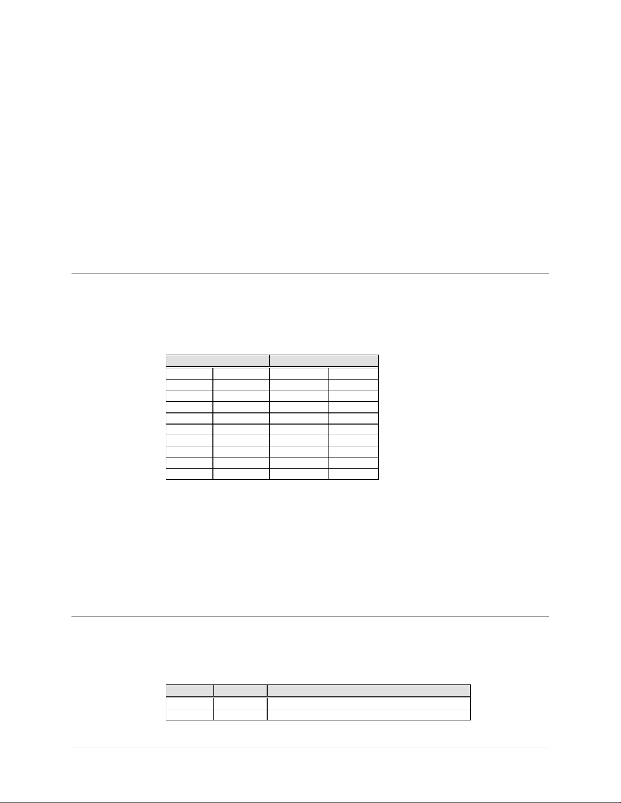
2.2 External Connections
Connections between the modem and other equipment are made through six connectors.
These connectors are listed in Table 2-1 and their locations are shown in Figure 2-1. The
use of each of these connectors is described in the following paragraphs.
Table 2-1 Rear Panel Connectors
Name Ref Design Connector
Type
DATA I/O NONE VARIOUS 4.2.1
REMOTE J6 9 PIN "D" 2.2.2 INTERFACE
MN/U-SDM309B Rev. # 2-2–1
Section Function
IBS/M1200P I/O
4.2.2
4.2.3
D&I/M1200P I/O
External Channel Unit
Page 27

Installation SDM-309B Satellite Modem
FAULT J7 9 PIN "D" 2.2.3 FORM C FAULT
RELAY CONTACTS
IF OUTPUT CP1 BNC 2.2.4 TX IF OUTPUT
IF INPUT CP2 BNC 2.2.5 RX IF INPUT
AC POWER NONE STANDARD 2.2.6 AC POWER INPUT
GND NONE #10-32 STUD 2.2.7 CHASSIS GROUND
2-2–2 MN/U-SDM309B Rev. #
Page 28

SDM-309B Satellite Modem Installation
Figure 2-1 Rear Panel View
MN/U-SDM309B Rev. # 2-2–3
Page 29
Installation SDM-309B Satellite Modem
2.2.1 Data I/O
For information and pinouts on the data connectors, please refer to the appropriate
subSection in Section 4.2 and Appendix C.
2.2.2 Remote (J6)
The remote connector on the modem is used to interface the Monitor and Control
functions to a remote location. This interface can be either RS232 or RS485. For a
complete discussion on the remote interface, refer to Sections 4.1.2 and 4.1.3.
2.2.2.1 Connector Pinout (J6)
The remote interface is provided on a 9 pin female "D" connector. Screw locks and
latching blocks are provided for mechanical security of the mating connector. The
remote connector is a DCE interface.
RS485 RS232
Pin# Name Pin# Name
1. GND 1.
2. 2. RD (RX)
3. 3. TD (TX)
4. +RX/TX 4.
5. -RX/TX 5. GND
6. 6. DSR
7. 7. RTS
8. +RX/TX 8. CTS
9. -RX/TX 9.
2.2.3 Fault (J7)
The fault connector on the modem is used to provide FORM C contact closures for the
purpose of fault reporting. There are three (3) FORM C summary fault contacts,
modulator, demodulator, and common equipment. For a complete discussion on what
faults are monitored refer to Section 3.1.5. To get a system summary alarm connect all
the FORM C contacts in parallel.
2.2.3.1 Connector Pinout (J7)
The fault interface is provided on a 9 pin female "D" connector. Screw locks and
latching blocks are provided for mechanical security on the mating connector.
Pin # Name
1. NO COMMON EQUIPMENT IS OK
2. COM
2-2–4 MN/U-SDM309B Rev. #
Page 30

SDM-309B Satellite Modem Installation
3. NC COMMON EQUIPMENT IS FAULTED
4. NO MODULATOR IS OK
5. COM
6. NC MODULATOR IS FAULTED
7. NO DEMODULATOR IS OK
8. COM
9. NC DEMODULATOR IS FAULTED
Note: A connection between the common (COM) and normally open (NO) contacts
indicates no fault.
2.2.4 IF Output (CP1)
This is the transmit IF connector. The output impedance is 75 ! and the output power
level is -5 to -15dBm. In normal operation, the output will be a QPSK modulated result
of the DATA I/O connector between 50 and 90 Mhz.
2.2.5 IF Input (CP2)
This is the receive IF connector. The input impedance is 75 !. For normal operation the
signal level needs to be between -30 and -55 dBm with a maximum composite level of 0
dBm. Signals between 50 and 90 Mhz are selected and demodulated to produce clock
and data at the DATA I/O connector.
2.2.6 AC Power
The AC power is supplied to the modem by a standard detachable, non locking, 3-prong
power cord. Normal input voltage is 90-132 VAC or 180-264 VAC, 47-63 Hz. Maximum
power consumption is less than 75 W.
Note: Damage may result if the incorrect input voltage is applied to this connector. If
there is any question of the compatibility, DO NOT connect up the unit until EFDATA
has been contacted.
2.2.7 GND
A#10-32 stud is available on the rear for the purpose of connecting a common chassis
ground between all of the equipment.
2.3 System Requirements
The standard modem with all the cards installed (Figure 1-3), is full duplex QPSK
satellite modem. The system can also be configured for TX only or RX only.
For a TX only system, the demodulator (0778-X) and decoder (2133, 0949, or 0701) are
removed. You also must enter the Utility Menu on the front panel and select OP MODE
MN/U-SDM309B Rev. # 2-2–5
Page 31

Installation SDM-309B Satellite Modem
(Operation Mode). Enter the menu and select TX only. This will mask the receive faults
and receive stored faults in the faults menu.
For a RX only system, the modulator (0773-X) is removed. Enter the Utility Menu on the
front panel and select OP MODE). Enter the menu and select RX only. This will mask
the transmit faults and transmit stored faults in the faults menu.
The modem interface is configured by the selection of the data interface card. Refer to
Section 4.2 for discussion on the data interfaces.
The modem data/code rate is configured by the installation of a daughter card (0715 or
0930) on the modulator and a daughter card (0698 or 0929-X) on the demodulator. The
UTILITIES function must be set up to be compatible with the daughter cards. Refer to
Section 3.1.8 for information on the UTILITIES function. The modem will be set up to
match the daughter cards when it is shipped from the factory.
2.4 System Installation
After unpacking the modem per Section 2.1, installation of the modem can be done as
follows:
a. Mount the modem chassis in the assigned position in the equipment rack.
b. Connect the cables on the rear panel to the appropriate location. Refer to Section
2.2 for connector pinouts, placement, and function.
c. Open the front panel and verify the three (3) main cards and the M&C and Data
Interface cards are properly seated. Refer to Figure 1-3 for position of the cards.
When the cards are installed correctly, the color of the card guides on the chassis
will match the color of the card ejectors on the cards.
d. Before turning on the power switch, read and become familiar with Section 3.1,
the Front Panel Operation.
e. Turn on the power switch that is located inside the front panel.
f. Check for proper TX signal level and spectrum.
g. Check for proper RX signal level and spectrum.
h. If there is any problem on installation refer to Section 6.0 for trouble shooting
the system.
2-2–6 MN/U-SDM309B Rev. #
Page 32

3.1 SDM 309/M1200P Front Panel
3.1.1 General
The following is a Step by Step explanation and procedure for operating the SDM 309B
modem, hereafter referred to as the modem, with an internal IBS channel unit. The
complete front panel operation is described below.
The Modem front panel (Figure 3-1) provides the local user interface which is necessary
to configure and monitor status of the satellite modem. The front panel features a sixteen
character, two line LCD display and six key key-pad which provides for sophisticated
functions, yet is easy to use. Eight LED indicators are also present on the front panel to
provide overall status at a glance. All functions are accessible at the front panel by
entering one of five predefined ‘sELECT” categories or levels: Configuration
(CONFIG), Monitor, Faults, Stored Faults (StFaults), and Utility.
Chapter 3.
OPERATION
3.1.2 LED Indicators
General modem status and summary fault information is indicated by eight LED’s on the
front panel. The indicators are defined as follows:
Faults
Transmit (Red LED) Indicates that a M odulator fault or a Transmit Interface
fault condition exists.
Receive (Red LED) Indicates that a Demodulator/Decoder fault or a Receive
Interface fault condition exists.
Common (Red LED) Indicates that a common equipment fault condition exists.
Stored (Red LED) Indicates that a fault has been logged and stored. The
fault may or may not be active.
Status
Power On (Green LED) Indicates power is applied to the modem.
Transmitter On (Green LED) Indicates that the transmitter is currently on. This indicator
reflects the actual condition of the transmitter, as opposed
to the programmed condition.
Carrier Detect (Green LED) Indicates that the decoder is locked.
MN/U-SDM309B Rev. # 3–1
Page 33

Operation SDM-309B Satellite Modem
Test Mode (Yellow LED) Flashes when the modem is in a test configuration.
3.1.3 Front Panel Controls
The Modem is locally operated by using the front panel key-pad (Figure 3-1). The keypad consists of six keys: Enter, Clear, Right Arrow, Left Arrow, Up Arrow, and Down
Arrow. Each key has it’s own logical function or functions:
Enter Key The “Enter” key is used to select a displayed function or to
execute a change to the Modem’s configuration.
Clear Key The “Clear” key is used to back out of a selection or to cancel
a configuration change which has not been executed using
the “Enter” key. Pressing the “Clear” key generally returns the
display to the previous selection.
Left & Right Arrow Keys These keys are used to move to the next selection or to move
the cursor for certain functions.
Up & Down Arrow Keys These keys are used primarily to change configuration data
(numbers) but are also used at times to move from one
Section to another.
The Modem responds by beeping whenever a key is pressed. A single beep indicates that
the key pressed was a valid entry and the appropriate action was taken. However, a
double beep when a key is pressed indicates that the key pressed was an invalid entry.
The Modem front panel control uses a tree structured menu system (Figures 3-2 to 3-7)
to access and execute all functions. The base level of this structure is the sign-on
message which is displayed at the front panel upon modem power up. Line one of the
sign-on message is the modem model number (SDM309) and line two is the version
number of the firmware implemented in your modem. The main level of the menu system
is the ‘sELECT” menu which may be accessed from the base level by pressing any of the
arrow keys. From the ‘sELECT” menu you may select any one of five functional
categories: configuration functions, monitor functions, fault functions, stored fault
functions or utility functions. Use the right and left arrow keys to move from one
selection to another, when the desired function is displayed on line two you can enter
that level by pressing the “Enter” key. Once you have entered the functional level of your
choice, move to the desired function by using the right and left arrow keys. Refer to the
following text for information on individual functional categories and there functions.
3–2 MN/U-SDM309B Rev. #
Page 34

SDM-309B Satellite Modem Operation
Figure 3-1 Front Panel View
MN/U-SDM309B Rev. # 3–3
Page 35

Operation SDM-309B Satellite Modem
3.1.4 Configuration
Modem configuration may be viewed or changed by entering the “CONFIG” level from
the ‘sELECT” menu on the front panel. After entering the “CONFIG” menu, use the
right and left arrow keys to select “MOD”, “DEMOD”, or “INTERFACE” configuration.
Enter the selected configuration menu by pressing the “ENTER” key. Use the right and
left arrow keys to view the selected configuration parameters. If it is desired to change a
configuration parameter press the “Enter” key to begin the change process at which point
you can use the arrow keys to make the changes. After the changes are made and the
display represents the correct parameters execute the change by pressing the “Enter” key.
When the “Enter” key is pressed the necessary programming is initiated by the modem.
If you decide not to change the parameter prior to executing the change simply press the
“Clear” key. The following notes describe each configuration function in detail.
3.1.4.1 MOD Configuration
TXA Transmitter rate selection. Select one of four predefined transmitter coder/data
rate combinations or a variable rate selection.
On entry the current transmitter rate is displayed with the flashing cursor on
the first character of the code rate on line one. The data rate is displayed on
line two. Use the arrow keys to select one of four predefined rates. Filters that
are not present may display as “N/A” (not assigned) and can not be
programmed. If your modem is equipped with the variable rate option you can
also select TXV and enter the desired data rate.
To change the rate using the variable rate selection, press the “ENTER” key
when “TXV is displayed. A flashing cursor w ill be display ed on the first
character of the coding type on line one. Use the right and left arrow keys to
move the flashing cursor and the up and down arrow keys to increment or
decrement the digit at the flashing cursor. Press the “ENTER” key to execute
the change.
Note:
When the TX Rate has been programmed, the transmitter is
automatically turned off, to prevent swamping of other channels. To turn on
the transmitter, use the “RF_Out” function.
TX_Freq Programs the modulator transmit frequency between 50mhz and 90MHz or
100MHz and 180MHz in 2.5 KHz Steps.
On entry the current transmitter frequency is displayed with the flashing cursor
on the first character. Use the right and left arrow keys to move the flashing
cursor and the up and down arrow keys to increment or decrement the digit at
the flashing cursor. Press the “ENTER” key to execute the change.
Note:
The transmitter frequency is programmable within the specified range
(50 - 90 MHz or 100 - 180 MHz ) in 2.5 KHz Steps. When the transmitter
frequency is changed, the transmitter is automatically turned off to prevent the
possible swamping of other channels. To turn the transmitter on, use the
“RF_OUT” function.
RF_Out Programs the modulator output to On or Off.
On entry the current status of the output is displayed with the flashing cursor
on the first character. Use the arrow keys to select ON or OFF. Press the
“ENTER” key to execute the change.
3–4 MN/U-SDM309B Rev. #
Page 36

SDM-309B Satellite Modem Operation
TX_Power Programs the modulator output power level from -5 dB to -30 dBm in .5 dB
Steps.
On entry the current transmitter power level is displayed w ith the flashing
cursor on the first character. The up and down keys are used to increase or
decrease the output power level in .5 dBm Steps. Press the “ENTER” key to
execute the change.
Note: If your modem has the high power Mod option installed (-11
modulator), you must change the output power range on the front panel. Enter
the Utility menu and find Pow Adj. Press the “ENTER” key and adjust the
maximum output power to read +5.0 dB using the up arrow. T his w ill make the
TX power read +5.0 to -20.0 dB, the output range of a high power mod.
DifEncdr Programs the differential encoder On or Off.
On entry the current status of the DifEncdr is displayed with the flashing cursor
on the first character. Use the arrow keys to select ON or OFF. Press the
“ENTER” key to execute the change.
CW_Mode * Programs the modem for continuous wave mode. Three modes of operation
are available: center, dual, and offset modes.
Center Mode:
Generates a carrier at the current modulator frequency. This can be used to
measure the output power and output frequency.
Dual Mode:
Generates a dual side-band suppressed carrier signal. Side-bands are at one
half (1/2) the symbol rate from the carrier. This is used to check the channel
balance and carrier null.
Offset Mode:
Generates a single upper side-band suppressed carrier signal. The upper
side-band is at one quarter (1/4) the symbol rate from the carrier. This is used
to check the quadrature.
On entry the “CENTER” mode is displayed. T o activ ate this test mode press
the “ENTER” key. Use the arrow keys to select the “DUAL or the “O FFSET ”
modes. To return to the “CONFIG” menu press the “CLEAR” key.
Note: When the “CLEAR” key is pressed, the modem is configured to the
state it was in before “CWMode” was invoked and the transmitter is
automatically turned off to prevent the possible swamping of other channels.
To turn the transmitter on use the “RF_OUT” function.
3.1.4.2 DEMOD Configuration
MN/U-SDM309B Rev. # 3–5
Page 37

Operation SDM-309B Satellite Modem
RXA Receiver rate selection. Select one of four predefined receiver
decoder/data rate combinations or a variable rate selection.
On entry the current receiver rate is displayed with the flashing
cursor on the first character of the code rate on line one. The data
rate is displayed on line two. Use the arrow keys to select one of four
predefined rates. Filters that are not present may display as “N/A”
(not assigned) and can not be programmed. If your modem is
equipped with the variable rate option you can also select TXV and
enter the desired data rate.
To change the rate using the variable rate selection, press the
“ENTER” key when “RX V” is display ed. A flashing cursor w ill be
displayed on the first character of the coding type on line one. Use
the right and left arrow keys to move the flashing cursor and the up
and down arrow keys to increment or decrement the digit at the
flashing cursor. Press the “ENTER” key to execute the change.
RX_freq Programs the demodulator receive frequency between 50 MHz and
90 MHz or 100 MHz and 180 MHz in 2.5 KHz Steps.
On entry the current receive frequency is displayed with the flashing
cursor on the first character. Use the right and left arrow keys to
move the flashing cursor and the up and down arrow keys to
increment or decrement the digit at the flashing cursor. Press the
“ENTER” key execute the change.
Note: The receiver frequency is programmable within the specified
range (50 - 90 MHz or 100 - 180 MHz ) in 2.5 KH z Steps.
DifDecdr Programs the differential decoder On or O ff.
On entry the current status of the differential decoder is displayed
with the flashing cursor on the first character. Use the arrow keys to
select ON or OFF. Press the “ENTER” key to ex ecute the change.
IFLoopBk *Programs the modem for IF loopback operation. When the IF loop-
back is turned on the demodulator input is connected to the
modulator output through an attenuator and the demodulator is
programmed to the same frequency as the modulator. An attenuator
within the modem connects the IF out to the IF in. When IF loopback
is turned off the demodulator is turned to it’s previous frequency and
is reconnected to the IF input. See Figure 3-8 for a block diagram of
IF loopback operation.
On entry the current status of the IF loopback is displayed with a
flashing cursor on the first character. Use the arrow keys to select
ON or OFF. Press the “ENTER” key to ex ecute the change.
RFLoopBk *Programs the modem for RF loopback operation. When RF
loopback is turned on the demodulator is programmed to the same
frequency as the modulator. When RF loopback is turned off the
demodulator is tuned to it’s previous frequency. See Figure 3-9 for a
block diagram of RF loopback operation.
On entry the current status of the RF Loopback is displayed with the
flashing cursor on the first character. Use the arrow keys to select
ON or OFF. Press the “ENTER” key to ex ecute the change.
3–6 MN/U-SDM309B Rev. #
Page 38

SDM-309B Satellite Modem Operation
SWP-RACQ Programs the sweep reacquisition mode time duration. The time
selected with this parameter is the time that the modem will remain in
a narrow sweep (± 10%) after acquisition has been accomplished.
After this timer runs out the modem will return to the normal sweep.
On entry the current programmed setting is displayed with a flashing
cursor on the first character. Use the right and left arrow keys to
move the flashing cursor and the up and down arrow keys to
increment and decrement the digit at the flashing cursor. Select the
number of seconds for the reacquisition mode from 0 to 999
seconds. Press the “ENTER” key to execute the change.
**SWP_CNTR Programs the sweep center frequency for the directed sweep
function. The sweep center frequency may be set in the range from
+25000Hz to -25000Hz.
On entry the current programmed setting is displayed with a flashing
cursor on the first character. Use the right and left arrow keys to
move the flashing cursor and the up and down arrow keys to
increment and decrement the digit at the flashing cursor. Select the
sweepcenter frequency from -25000Hz to +25000Hz. Press the
“ENTER” key to execute the change.
When in directed sweep, the value from the sweep monitor screen
(when the modem was last locked) should be entered for the sweep
center frequency.
**SWP_RNGE Programs the overall travel of the sweep width range during
acquisition in the directed sweep mode. The sweep width may be set
from 0 Hz to 50000 Hz. (When set at 50000 Hz, the modem is in the
fast acquisition mode).
On entry the current programmed setting is displayed with a flashing
cursor on the first character. Use the right and left arrow keys to
move the flashing cursor and the up and down arrow keys to
increment and decrement the digit at the flashing cursor. Select a
sweep range from 0 Hz to 50000 Hz. Press the “ENTER” key to
execute the change.
When in directed sweep, the smaller the range is, the faster the
modem will lock, provided the sweep center frequency is close.
**SWP_DIR Programs the direction of the sweep travel in the directed sweep
mode.
On entry the current programmed setting is displayed with the
flashing cursor on the first character. Use the arrow keys to select
Forward (+) or Reverse (-). Press the “ENTER” key to execute the
change.
BERT_set This function is used to set the BER threshold.
If the BER threshold set is exceeded a receive fault will be indicated
by the modem status indicators. BER threshold may be set from 1E3 to 1E-8 or may be disabled by specifying NONE.
On entry the current setting of the BER threshold is dis played. Use
the up and down arrow keys to select the desired setting. Press the
“ENTER” key to execute the change.
* Indicates Test Mode configuration option.
**These windows only show up when the Fast Acquisition has been
turned on in the “Utility” menu.
MN/U-SDM309B Rev. # 3–7
Page 39

Operation SDM-309B Satellite Modem
3.1.4.3 Interface Configuration
TX_clock Programs the clock source for the modem transmitter clock. “Internal” sets
the TX clock to operate from the modem internal clock, this is also the
fallback clock. “External” sets the TX clock to operate from the ex ternal
reference clock. This clock must be frequency locked to the data that is
being transmitted. “TX Terrestrial” sets the TX clock to recov er timing from
the incoming data.
On entry the current transmit clock setting is displayed with the flashing
cursor on the first character. Use the arrow keys to select “Internal”,
“External Reference”, or TX Terrestrial” clock. Press the “EN T ER” key to
execute the change.
BUF_Clk Programs the interface plesiochronous buffer output clock. “TX T errestrial”
sets the buffer output clock to recover timing from the incoming TX data
clock. “External” sets this clock source to the external reference clock.
‘satellite” sets the output buffer clock to the satellite clock, this is also the
fallback clock. If ‘satellite” is selected, the doppler shift caused by the
satellite will not be removed. “Internal” set the buffer clock to operate from
the modem internal clock.
On entry the current setting of the plesiochronous buffer clock is displayed
with the flashing cursor on the first character. Use the arrow keys to select
‘satellite”, “Internal”, “Ext Ref”, or “TX_Terr” for the buffer clock. Press the
“ENTER” key to execute the change.
RX_Clock Programs the RX clock to “Normal” or “Inverted”.
On entry the current status of the RX Clock is displayed w ith the flashing
cursor on the first character. Use the arrow keys to select “Normal” or
“Inverted”. Press the “ENTER” key to execute the change.
Ext_REF Program the external reference clock input frequency between 8 KHz and
10 MHz in 8 KHz Steps.
On entry the current setting for the external reference is displayed with the
flashing cursor on the first character. Use the right and left arrow keys to
move the flashing cursor and the up and down arrow keys to increment or
decrement the digit at the flashing cursor. Press the “ENTER” key to
execute the change.
BBLoopBk *Programs the modem for baseband loopback operation. When baseband
loopback is turned on data is looped back on the customer side of the
interface. This is a bidirectional loopback of the baseband data. See Figure
3-10 for a block diagram of baseband loopback operation.
On entry the current status is displayed with the flashing cursor on the first
character. Use the arrow keys to select ON or OFF. Press the “ENTER” key
to execute the change.
INTF_LBk *Programs the modem for interface loopback operation. When interface
loop-back is turned on data is looped back on the modem side of the
interface. This is a bidirectional loopback of the data after the baseband
data has had the 16/15 overhead added. See Figure 3-11 for a block
diagram of interface loopback operation.
On entry the current status is displayed with the flashing cursor on the first
character. Use the arrow keys to select ON or OFF. Press the “ENTER” key
to execute the change.
3–8 MN/U-SDM309B Rev. #
Page 40

SDM-309B Satellite Modem Operation
CODING Programs the modem for “AMI ”, “B8ZS”, “B6ZS”, or “HDB 3” coding of the
baseband data.
On entry the current coding format is displayed. Use the arrow keys to
select the desired coding format. Press the “ENTER” key to execute the
change.
TX_2047 *Programs the modem to insert a 2047 pattern in lieu of the normal transmit
data.
On entry the current status is displayed with the flashing cursor on the first
character. Use the arrow keys to select ON or OFF. Press the “ENTER” key
to execute the change.
TXD_FLT Transmit Data Fault. This configuration function is used to select a Transmit
Interface fault monitor of AIS, Data, or None. When AIS (Alarm Indication
Signal) is selected the TX_INTF (Transmit Interface) fault “Data/AIS” is
monitoring a fault condition of all 1’s from customer data input to the
modem. When Data_Flt is selected, the TX_INTF fault “Data/AIS” is
monitoring a fault condition of all 1’s or all 0’s. This is referred to as a data
stable condition which means that the data is not transitioning. When None
is selected, the TX_INTF fault “Data/AIS” is not activated. On entry the
current TX Data fault that is being monitored is displayed with the flashing
cursor on the first character.
Use the arrow keys to select Data, AIS, or None. Press the “ENTER” key to
execute the change.
RXD_FLT Receive Data Fault. This configuration function is used to select a Receive
Interface fault monitor of AIS, Data, or None. The data monitored for
Receive Data is coming from the Satellite. Refer to TXD_FLT for a
description of the function choices.
On entry the current RX Data fault that is being monitored is displayed with
the flashing cursor on the first character. Use the arrow keys to select Data,
AIS, or None. Press the “ENTER” key to execute the change.
BUF_SIZE This configuration function is used to set the size of the plesiochronous
buffer.
On entry the current plesiochronous buffer length is displayed. Use the up
and down arrow keys to select the desired buffer size. You may select from
384 to 262,144 bits in increments of sixteen. Press the “ENTER” key to
execute the change.
BUF_CNTR This configuration function is used to center the plesiochronous buffer.
Press the “ENTER” key twice to center the plesiochronous buffer.
READ_ERR This configuration is used to select the read error function mode. Frame or
2047 errors may be selected.
On entry the current read error mode is displayed. Use the arrow keys to
select “2047” errors or “FRAME” errors as desired. Press the “ENTER” key
to display and monitor the selected errors. To exit the read error mode press
the “CLEAR” key.
Dscrmblr Programs the demod/decoder for descrambler On or Off.
On entry the current status of the descrambler is displayed with the flashing
cursor on the first character. Use the arrow keys to select ON or OFF. Press
the “ENTER” key to execute the change.
Scramblr Programs the modulator for scrambler On or Off.
On entry the current status of the scrambler is displayed with the flashing
cursor on the first character. Use the arrow keys to select ON or OFF. Press
the “ENTER” key to execute the change.
* Indicates Test Mode configuration option.
MN/U-SDM309B Rev. # 3–9
Page 41

Operation SDM-309B Satellite Modem
3.1.5 Monitor
When the “MONITOR” level is entered use the right and left arrow keys to select the
desired monitor function. Each monitor function is displayed in real time as long as it is
selected.
Raw_BER - Raw bit error rate.
* Range: <1.0E-4 to >2550E-4
Cor_BER - Corrected bit error rate.
* Range: <1.0E-8 to >1E-3
Eb/N0 - Energy(bit)/noise ratio.
* Range: <3.2 dB to >16.0 dB
Swp_Freq - Sweep Monitor**
*Range: -25,000 Hz to +25,000 Hz
RxSignal - Receive signal level.
* Range: <-60 dBm to >-30 dBm
3.1.6 Faults
FIL_STAT - Plesiochronous buffer fill status in percent.
* Range: 1% to 99%
FRM_ERR/2047_ERR - Framing pattern bit error rate. Monitors the currently
selected READ_ERR function.
* Range: <8.0E-4 to >1.4E-3
* When the decoder loses lock no data is available and is so indicated.
** Sweep Frequency only shows up in the “Monitor” menu if the Fast Acquisition
has been turned on in the “Utility” menu.
The “FAULTS” level is accessible from the ‘sELECT” menu. Faults are similar to
monitor functions as they display the current fault status of the group being displayed.
Use the right and left arrow keys to move between the fault groups: Mod_Flts
(modulator faults), Dmd_Flts (demodulator faults), CEQ_Flts (common equipment
faults), TX_INTF (transmitter interface faults), and RX_INTF (receiver interface faults).
The current faults status is displayed on line two of the display in real time. Faults status
is display as “+” (plus) or “-” (minus) for each parameter monitored, “+” indicates that a
fault exists and “-” indicates that no fault exists. To display labels for individual faults
press the “Enter” key. Use the left and right arrow keys to move the flashing cursor to the
fault you wish to identify. The label for that fault is immediately displayed on line one of
the display. The “Clear” key can be used to exit this level of operation and return to the
previous level. The following lists outline the faults monitored and displayed in each
group.
3–10 MN/U-SDM309B Rev. #
Page 42

SDM-309B Satellite Modem Operation
3.1.6.1 Mod_Flts - Modulator Faults
RF_Syn Modulator RF synthesizer fault.
Data_Clk Transmit data clock activ ity indicator.
TClk_Syn Transmit clock synthesizer fault.
I-Channl I channel activity fault.
Q-Channl Q channel activity fault.
AGC_level Automatic gain control level fault.
Module Modulator module fault. Typically indicates that the modulator module is
missing or will not program.
3.1.6.2 Dmd_Flts - Demodulator/Decoder Faults
C_Detect Carrier detect fault. Indicates that the decoder is not locked.
RF_Syn Demodulator RF synthesizer fault.
Data_Clk Receive data clock activity fault.
I-Channl I channel activity fault.
Q-Channl Q channel activity fault.
BERthrsh Secondary alarm result of BERT_set in the DEMOD configuration menu.
Module Demodulator/decoder module fault. Ty pically indicates that the demod/decoder
module is missing or will not program.
3.1.6.3 CEQ_Flts - Common Equipment Faults
Battery Battery fault.
-12 volt Negative 12 volt power supply fault.
+12 volt Plus 12 volt power supply fault.
+5 volt Plus 5 volt power supply fault.
Intrface Interface module fault. Typically indicates that the interface module is missing or
will not program.
3.1.6.4 TX_INTF - Transmit Interface Faults
Data/AIS Data or Alarm indication Signal. When Data_FLT is selected in the Interface
Configuration menu the fault indicates a Data stable condition. When AIS is
selected, fault indicates data is all 1’s. Refer to Section 1.2.3 (Interface
Configuration) for a detailed description of these faults.
TX_PLL Transmitter phase locked loop fault. Indicates that the transmitter PLL is not
locked.
CLK_ACT Activity detector alarm of the selected interface transmit clock. The interface
will fall back to the internal clock when this fault is active.
3.1.6.5 RX_INTF - Receive Interface Faults
BUF_UNFL Buffer underflow fault. Indicates that a plesiochronous buffer underflow has
occurred.
BUF_OVFL Buffer overflow fault. Indicates that a plesiochronous buffer overflow has
occurred.
MN/U-SDM309B Rev. # 3–11
Page 43

Operation SDM-309B Satellite Modem
Data/AIS Data or Alarm Indication Signal. When Data_FLT is selected in the Interface
Configuration menu the fault indicates a Data stable condition. When AIS is
selected, the fault indicates data is all 1’s. Refer to Section 4.3 (Interface
Configuration for a detailed description of these faults.
FRM_BER Frame BER fault. Indicates that the frame BER exceeds 1E-3.
BW_ALM Backward Alarm Fault.
RX_PLL Receive Phase Locked Loop Fault.
Buff_Clk Activity detector alarm of the selected interface receiv e clock. T he interface
will fall back to the satellite clock when this fault is active.
MUX_lock MUX lock fault. Indicates that the MUX is not locked.
3.1.7 Stored Faults
The Modem stores the first ten (Flt0 - Flt9) occurrences of fault status changes in each of
the six major fault categories. Each stored fault status change is stored with the time and
date of the occurrence. Stored faults may be viewed by entering the ‘stFaults” level from
the ‘sELECT” menu. All stored faults may be cleared by executing the “CLEAR ??
StFaults” command from the ‘stFaults” level.
Stored faults are not maintained through a controller power on reset cycle. However, the
last known time is maintained in non volatile RAM and upon power up a common
equipment fault is logged (Flt0) with that time and date. On power up an additional
common equipment fault is also logged (Flt1) to indicate the power up time and date. So
on power up the power down and power up times are logged as common equipment fault
0 and common equipment fault 1.
3.1.8 Utility
Upon entering the ‘stFaults” level use the left and right arrow keys to move between the
six fault groups and the “CLEAR ?? StFaults” selections. The time and date of the first
stored faults status (Flt0) for the selected group will be displayed alternately on line two
of the display. Use the up and down arrow keys to cycle through the selected group’s
stored faults status (Flt0 - Flt9). To display the faults status associated with the displayed
time and date press the “Enter” key, at this time you can use the right and left arrow keys
to move the flashing cursor to the fault you wish to identify.
To clear the stored faults currently logged simply press the “ENTER” key when the
“CLEAR ?? StFaults” selection is displayed.
Note: Faults are stored in time sequence with the oldest faults status change stored in
Flt0 and the most recent in Flt9. Only the first ten faults status changes are stored and all
stored faults which have not been used indicate “No Fault” on the display.
The utility functions provide a means to set the time and date of the modem real time
clock circuit. Provisions are also made for assigning data and code rates to the modulator
and demodulator. A lamp test function is provided for testing of the front panel optical
indicators.
3–12 MN/U-SDM309B Rev. #
Page 44

SDM-309B Satellite Modem Operation
After entering the “UTILITY” functions level use the right and left arrow keys to select
the utility function of interest. The current time and date can be displayed and changed as
required. Access to the transmitter and receiver Data/Code Rate assignment and the lamp
test functions are also available from within the utility functions level.
Note: The selection of data/code rates in the “UTILITY” program must match the
hardware filters installed on the modulator and demodulator modules.
The utility functions are as follows:
Time Time of day set/display function.
The current time that the modem is set for is displayed
when selected. To set the modem time press the “ENTER”
key and use the right and left arrow keys to position the
flashing cursor over the parameter to be changed. Use the
up and down arrow keys to change the parameter to the
desired value. Once the parameters are displayed as
desired press the “ENTER” key to set the time.
Date Date set/display.
Follow the same procedure as outlined for the time function
to view and set the date.
LAMP TEST ?? Lamp test function used to illuminate all the front panel
indicators for three seconds.
Press the “ENTER” key to turn on all of the front panel
indicators for three seconds.
Address/Parity/Baud Rate The current modem address, parity selection and selected
baud rate of the modem is displayed. This in only a monitor
function. No changes can be made from this menu.
On entry the currently set address of the modem will be
displayed (0 to 255) on the first line. The currently set
parity, even or odd, will be displayed on the second line.
The currently set baud rate from 110 to 9600 will also be
displayed on the second line.
POW ADJ. Modulator Power Adjust Offset.
Allows the operator to offset the modulator output power
readout in the configuration menu. This will be the highest
modulator power that will be displayed and programmed.
This feature does not actually change the modulator power
level. The function is to change the actual reading to
display an offset value in the monitor. The modulator
Power Offset can be set between +20.0 to -20.0 dB in 0.5
dB increments.
Note: The maximum output power adjust, set in this
window, must match the maximum output pow er of the
modulator installed in the modem. In a switching system
the backup modem must be set the same as the prime
modem or a fault will occur.
MN/U-SDM309B Rev. # 3–13
Page 45

Operation SDM-309B Satellite Modem
OP MODE Operation Mode. Programs the modem operation for TX
only, RX only, or Duplex operation.
On entry the flashing cursor is on the first character of the
display. Use the arrow keys to select TX only , R X only , or
Duplex. Press the “ENTER” key to execute the change.
When TX only or RX only is selected, the appropriate faults
are masked from the Faults and Stored Faults menu.
Fast ACQ Fast Acquisition function.
Turns the fast acquisition and directed sweep function ON
or OFF. When the fast acquisition has been turned OFF,
the Swp_Cntr, SWP_Rnge and SWP_DIR windows in the
configuration menu are disabled and do not appear. Also,
in the “Monitor” menu, Swp_Freq will not appear. When
turned “OFF” fast acquisition does not occur.
INTRFACE This is a monitor function that displays the interface that
has been selected on the M&C card. No changes are
accepted from the front panel.
Filter Adjust Variable Rate Filters K factor settings. This is a factory
setting and the operator is not allowed to enter this
parameter without authorization from EFData service
department. Failure to comply will result in a modem
failure.
Assign TX_Fltrs Transmit filter display/assignment utility. Used to v iew
current filter rate assignments and to make filter rate
reassignments. The modulator has four symbol rate filters.
Each filter is for a specific symbol rate. The data rate and
code rate for each filter must be established upon initial
modulator installation and when circumstances indicate the
need to do so. Filters are designated as A, B, C, and D.
To view the current filter assignments press the “ENTER”
key when the “Assign TX_Fltrs” selection is displayed from
the utility functions menu. On line one of the display will be
TXA” which indicates transmitter filter A. Following “T XA”
on line one will be the code rate (1/2 or 3/4) or “N/A” which
indicates that the filter is not assigned. On line two will be
the data rate assigned to filter “A”. Use the right and left
arrow keys to see the assignments for filters B, C, and D
(TXB, TXC, and T XD).
If it is desired to change a filter assignment press the
“ENTER” key when the data for that filter is displayed. Use
the right and left arrow keys until the flashing cursor is at
the parameter to be changed. Then use the up and down
arrow keys to change that parameter. When all changes
are made press the “Enter” key to confirm the assignment.
Some filters may have parameters preprogrammed in the
filter board hardware. If the filter parameters are
preprogrammed the previously described programming
techniques will be disabled.
Note: These assignments are used for the selection of
“TXR” (Transmitter Rate) in the configuration functions
menu.
The parameter “N/A” is used to indicate that the specific
filter is not present.
3–14 MN/U-SDM309B Rev. #
Page 46

SDM-309B Satellite Modem Operation
Assign RX_Fltrs Receive filter display/assignment utility. Used to view
current filter rate assignments and to make filter rate
reassignments.
Refer to the previous text under “Assign TX_Fltrs”. T he
receive filters assignments are basically identical.
MN/U-SDM309B Rev. # 3–15
Page 47

Operation SDM-309B Satellite Modem
Figure 3-2 Menu Tree
3–16 MN/U-SDM309B Rev. #
Page 48

SDM-309B Satellite Modem Operation
Figure 3-3 Menu Tree
MN/U-SDM309B Rev. # 3–17
Page 49

Operation SDM-309B Satellite Modem
Figure 3-4 Menu Tree
3–18 MN/U-SDM309B Rev. #
Page 50

SDM-309B Satellite Modem Operation
Figure 3-5 Menu Tree
MN/U-SDM309B Rev. # 3–19
Page 51

Operation SDM-309B Satellite Modem
Figure 3-6 Menu Tree
3–20 MN/U-SDM309B Rev. #
Page 52

SDM-309B Satellite Modem Operation
Figure 3-7 Menu Tree
MN/U-SDM309B Rev. # 3–21
Page 53

Operation SDM-309B Satellite Modem
Figure 3-8 IF Loopback
3–22 MN/U-SDM309B Rev. #
Page 54

SDM-309B Satellite Modem Operation
Figure 3-9 RF Loopback
MN/U-SDM309B Rev. # 3–23
Page 55

Operation SDM-309B Satellite Modem
Figure 3-10 Interface Loopback
3–24 MN/U-SDM309B Rev. #
Page 56

SDM-309B Satellite Modem Operation
Figure 3-11 Baseband Loopback
MN/U-SDM309B Rev. # 3–25
Page 57

Operation SDM-309B Satellite Modem
3.2 Drop And Insert Front Panel Operation
3.2.1 General
The following is a Step by Step explanation and procedure for operating the SDM 309B
modem, hereafter referred to as the modem, with an internal drop and insert channel unit.
The operation of the front panel is the same “look and feel” as the SDM 309 modem
without the drop and insert channel unit, except there are additional commands for the
drop and insert channel unit. The complete front panel operation is described below.
The Modem front panel control uses a tree structured menu system (Figure 3-12 to 3-17)
to access and execute all functions. The base level of this structure is the sign-on
message which is displayed at the front panel upon modem power up. Line one of the
sign-on message is the modem model number (SDM308-5) and line two is the version
number of the firmware implemented in your modem. The main level of the menu system
is the ‘sELECT” menu which may be accessed from the base level by pressing any of the
arrow keys. From the ‘sELECT” menu you may select any one of five functional
categories: configuration functions, monitor functions, fault functions, stored fault
functions or utility functions. Use the right and left arrow keys to move from one
selection to another, when the desired function is displayed on line two you can enter
that level by pressing the “Enter” key. Once you have entered the functional level of your
choice, move to the desired function by using the right and left arrow keys. Refer to the
following text for information on individual functional categories and there functions.
3.2.2 Configuration
Modem configuration may be viewed or changed by entering the “CONFIG” level from
the ‘sELECT” menu on the front panel. After entering the “CONFIG” menu, use the
right and left arrow keys to select “MOD”, “DEMOD”, or “INTERFACE” configuration.
Enter the selected configuration menu by pressing the “ENTER” key. Use the right and
left arrow keys to view the selected configuration parameters. If it is desired to change a
configuration parameter press the “Enter” key to begin the change process at which point
you can use the arrow keys to make the changes. After the changes are made and the
display represents the correct parameters execute the change by pressing the “Enter” key.
When the “Enter” key is pressed the necessary programming is initiated by the modem.
If you decide not to change the parameter prior to executing the change simply press the
“Clear” key. The following notes describe each configuration function in detail.
3–26 MN/U-SDM309B Rev. #
Page 58

SDM-309B Satellite Modem Operation
3.2.2.1 MOD Configuration
TXA Transmitter rate selection. Select one of four predefined
transmitter coder/data rate combinations or a variable rate
selection.
On entry the current transmitter rate is displayed with the flashing
cursor on the first character of the code rate on line one. The data
rate is displayed on line two. Use the arrow keys to select one of
four predefined rates. Filters that are not present may display as
“N/A” (not assigned) and can not be programmed. If your modem
is equipped with the variable rate option you can also select TXV
and enter the desired data rate.
TX_Freq Programs the modulator transmit frequency between 50 and 90
MHz or 110 and 180 MHz in 2.5 KHz Steps.
On entry the current transmitter frequency is displayed with the
flashing cursor on the first character. Use the right and left arrow
keys to move the flashing cursor and the up and down arrow keys
to increment or decrement the digit at the flashing cursor. Press
the “ENTER” key to execute the change.
To change the rate using the variable rate selection, press the
“ENTER” key when “TX V is display ed. A flashing cursor w ill be
displayed on the first character of the coding type on line one. Use
the right and left arrow keys to move the flashing cursor and the up
and down arrow keys to increment or decrement the digit at the
flashing cursor. Press the “ENTER” key to execute the change.
Note:
The transmitter frequency is programmable within the
specified range (50 - 90 MHz or 110 - 180 MHz ) in 2.5 KHz Steps.
When the transmitter frequency is changed, the transmitter is
automatically turned off to prevent the possible swamping of other
channels. To turn the transmitter on, use the “RF_OUT” function.
RF_Out Programs the modulator output to On or Off.
On entry the current status of the output is displayed with the
flashing cursor on the first character. Use the arrow keys to select
ON or OFF. Press the “ENTER” key to ex ecute the change.
TX_Power Programs the modulator output power level from -5 dB to -30 dBm
in 0.5 dB Steps.
On entry the current transmitter power level is displayed with the
flashing cursor on the first character. The up and own keys are
used to increase or decrease the output power level in 0.5 dBm
Steps. Press the “ENTER” key to execute the change.
Note:
If your modem has the high power Mod option installed (-11
modulator), you must change the output power range on the front
panel. Enter the Utility menu and find Pow Adj. Press the “ENTER”
key and adjust the maximum output power to read +5.0 dB using
the up arrow. This will make the TX power read +5.0 to -20.0 dB,
the output range of a high power mod.
DifEncdr Programs the differential encoder On or Off.
On entry the current status of the DifEncdr is displayed with the
flashing cursor on the first character. Use the arrow keys to select
ON or OFF. Press the “ENTER” key to ex ecute the change.
MN/U-SDM309B Rev. # 3–27
Page 59

Operation SDM-309B Satellite Modem
CW_Mode *Programs the modem for continuous wave mode. Three modes of
operation are available: center, dual, and offset modes.
Center Mode:
Generates a carrier at the current modulator frequency. This can
be used to measure the output power and output frequency.
Dual Mode:
Generates a dual side-band suppressed carrier signal. Side-bands
are at one half (1/2) the symbol rate from the carrier. This is used
to check the channel balance and carrier null.
Offset Mode:
Generates a single upper side-band suppressed carrier signal.
The upper side-band is at one quarter (1/4) the symbol rate from
the carrier. This is used to check the quadrature.
On entry the “CENTER” mode is displayed. T o activ ate this test
mode press the “ENTER” key. Use the arrow keys to select the
“DUAL or the “OFFSET” modes. To return to the “CONFIG” menu
press the “CLEAR” key.
Note: When the “CLEAR” key is pressed, the modem is
configured to the state it was in before “CWMode” was invoked
and the transmitter is automatically turned off to prevent the
possible swamping of other channels. To turn the transmitter on
use the “RF_OUT” function.
3.2.2.2 DEMOD Configuration
RXA Receiver rate selection. Select one of four predefined receiv er
RX_freq Programs the demodulator receive frequency between 50 and 90 MHz or
DifDecdr Programs the differential decoder On or Off.
decoder/data rate combinations or a variable rate selection.
On entry the current receiver rate is displayed with the flashing cursor on
the first character of the code rate on line one. The data rate is displayed
on line two. Use the arrow keys to select one of four predefined rates.
Filters that are not present may display as “N/A” (not assigned) and can
not be programmed. If your modem is equipped with the variable rate
option you can also select TXV and enter the desired data rate.
110 and 180 MHz in 2.5 KHz Steps.
On entry the current receive frequency is displayed with the flashing
cursor on the first character. Use the right and left arrow keys to move
the flashing cursor and the up and down arrow keys to increment or
decrement the digit at the flashing cursor. Press the “ENTER” key
execute the change.
Note: The receiver frequency is programmable within the specified
range (50 - 90 MHz or 110 - 180 MHz) in 2.5 KHz Steps.
On entry the current status of the differential decoder is displayed with
the flashing cursor on the first character. Use the arrow keys to select ON
or OFF. Press the “ENTER” key to execute the change.
3–28 MN/U-SDM309B Rev. #
Page 60

SDM-309B Satellite Modem Operation
IFLoopBk *Programs the modem for IF loopback operation. When the IF loopback
is turned on the demodulator input is connected to the modulator output
through an attenuator and the demodulator is programmed to the same
frequency as the modulator. An attenuator within the modem connects
the IF out to the IF in. When IF loopback is turned off the demodulator is
turned to it’s previous frequency and is reconnected to the IF input. See
Figure 3-8 for a block diagram of IF loopback operation.
On entry the current status of the IF loopback is displayed with a flashing
cursor on the first character. Use the arrow keys to select ON or OFF.
Press the “ENTER” key to execute the change.
RFLoopBk *Programs the modem for RF loopback operation. When RF loopback is
turned on the demodulator is programmed to the same frequency as the
modulator. When RF loop-back is turned off the demodulator is tuned to
it’s previous frequency. See Figure 3-9 for a block diagram of RF
loopback operation.
On entry the current status of the RF Loopback is displayed with the
flashing cursor on the first character. Use the arrow keys to select ON or
OFF. Press the “ENTER” key to execute the change.
SWP_RACQ This function sets the sweep reacquisition rate from 0 to 999 seconds.
The time selected with this parameter is the time that the modem will
remain in a narrow sweep (± 10%) after acquisition has been
accomplished. After this timer runs out the modem will return to the
normal sweep.
On entry the current programmed setting is displayed with a flashing
cursor on the first character. Use the right and left arrow keys to move
the flashing cursor and the up and down arrow keys to increment and
decrement the digit at the flashing cursor. Select the number of seconds
for the reacquisition mode form 0 to 999 seconds. Press the “ENTER”
key to execute the change.
**SWP_CNTR Programs the sw eep center frequency for the directed sweep function.
The sweep center frequency may be set in the range from +25000Hz to 25000Hz.
On entry the current programmed setting is displayed with a flashing
cursor on the first character. Use the right and left arrow keys to move
the flashing cursor and the up and down arrow keys to increment and
decrement the digit at the flashing cursor. Select the sweepcenter
frequency from -25000Hz to +25000Hz. Press the “ENTER” key to
execute the change.
When in directed sweep, the value from the sweep monitor screen (when
the modem was last locked) should be entered for the sweep center
frequency.
**SWP_RNGE Programs the overall travel of the sweep width range during acquisition in
the directed sweep mode. The sweep width may be set from 0 H z to
50000 Hz. (When set at 50000 Hz, the modem is in the fast acquisition
mode).
On entry the current programmed setting is displayed with a flashing
cursor on the first character. Use the right and left arrow keys to move
the flashing cursor and the up and down arrow keys to increment and
decrement the digit at the flashing cursor. Select a sweep range from 0
Hz to 50000 Hz. Press the “ENTER” key to execute the change.
When in directed sweep, the smaller the range is, the faster the modem
will lock, provided the sweep center frequency is close.
MN/U-SDM309B Rev. # 3–29
Page 61

Operation SDM-309B Satellite Modem
**SWP_DIR Programs the direction of the sweep travel in the directed sweep mode.
On entry the current programmed setting is displayed with the flashing
cursor on the first character. Use the arrow keys to select Forward (+) or
Reverse (-). Press the “ENTER” key to execute the change.
BERT_set This function is used to set the BER threshold.
If the BER threshold set is exceeded a receive fault will be indicated by
the modem status indicators.
BER threshold may be set from 1E-3 to 1E-8 or may be disabled by
specifying NONE.
On entry the current setting of the BER threshold is displayed. Use the
up and down arrow keys to select the desired setting. Press the “ENTER”
key to execute the change.
* Indicates Test Mode configuration option.
**These windows only show up when the Fast Acquisition has been
turned on in the “Utility” menu.
3.2.2.3 Interface Configuration
INS_Clk Programs the interface plesiochronous buffer
clock for Satellite, internal, external reference,
or Insert clock.
On entry the current setting of the
plesiochronous buffer clock is displayed with
the flashing cursor on the first character. Use
the arrow keys to select ‘satellite”, “Internal”,
“External Reference” or “Insert” for the buffer
clock. Press the “ENTER” key to execute the
change.
Ext_REF Programs the data rate of external reference.
Select either 1544 or 2048 Kbps.
On entry the current setting for the external
reference is displayed with the flashing cursor
on the first character. Use the arrow keys to
enter the external data rate desired. Press the
“ENTER” key to execute the change.
3–30 MN/U-SDM309B Rev. #
Page 62

SDM-309B Satellite Modem Operation
BBLoopBk *Programs the modem for baseband loopback
operation.
When baseband loopback is turned on insert
data is looped back on the customer side of
the interface.
Note: The drop data is hard wired into
loopback causing the BBLoopBk function to
affect only the insert data. See Figure 3-10 for
a block diagram of Baseband loopback
operation.
On entry the current status is displayed with
the flashing cursor on the first character. Use
the arrow keys to select ON or OFF. Press the
“ENTER” key to execute the change.
INTF_LBk *Programs the modem for interface loopback
operation.
When interface loopback is turned on data is
looped back on the modem side of the
interface. See Figure 3-11 for a block diagram
of Interface loopback operation.
On entry the current status is displayed with
the flashing cursor on the first character. Use
the arrow keys to select ON or OFF. Press the
“ENTER” key to execute the change.
Note: Interface loopback only works when
the TX data rate matches the RX data rate.
TX CODE Programs the transmitter for “AMI”, “HDB3”, or
“B8ZS” data.
On entry the current coding format is
displayed. Use the arrow keys to select the
desired coding format. Press the “ENTER”
key to execute the change.
RX CODE Programs the receiver for “AMI”, “HDB3”, or
“B8ZS” data.
On entry the current coding format is
displayed. Use the arrow keys to select the
desired coding format. Press the “ENTER”
key to execute the change.
TX_2047 *Programs the modem to insert a 2047
pattern in place of the normal transmit data.
On entry the current status is displayed with
the flashing cursor on the first character. Use
the arrow keys to select ON or OFF. Press the
“ENTER” key to execute the change.
MN/U-SDM309B Rev. # 3–31
Page 63

Operation SDM-309B Satellite Modem
TXD_FLT Transmit Data Fault. This configuration
function is used to select a Transmit Interface
fault monitor of AIS, Data, or none. When AIS
(Alarm Indication Signal) is selected the
TX_INTF (Transmit Interface) fault “Data/AIS”
is monitoring a fault condition of all 1’s from
customer data input to the modem. When
Data_Flt is selected, the TX_INTF fault
“Data/AIS” is monitoring a fault condition of all
1’s or all 0’s. This is referred to as a data
stable condition which means that the data is
not transitioning. When None is selected, the
TX_INTF fault “Data/AIS” is not activated.
On entry the current TX Data fault that is
being monitored is displayed with the flashing
cursor on the first character. Use the arrow
keys to select Data, AIS, or None. Press the
“ENTER” key to execute the change.
RXD_FLT Receive Data Fault. This configuration
function is used to select a Receive Interface
fault monitor of AIS, Data, or None. The data
monitored for Receive Data is coming from
the Satellite. Refer to TXD_FLT for a
description of the function choices.
On entry the current RX Data fault that is
being monitored is displayed with the flashing
cursor on the first character. Use the arrow
keys to select Data, AIS, or None. Press the
“ENTER” key to execute the change.
BUF_SIZE This configuration function is used to set the
size of the plesiochronous buffer.
On entry the current plesiochronous buffer
length is displayed. Use the up and down
arrow keys to select the desired buffer size.
You may select from 1 to 32 seconds. Press
the “ENTER” key to execute the change.
BUF_CNTR This configuration function is used to center
the plesiochronous buffer. Press the “ENTER”
key twice to center the plesiochronous buffer.
READ_ERR T his configuration is used to select the read
error function mode. Frame or 2047 errors
may be selected.
On entry the current read error mode is
displayed. Use the arrow keys to select
“2047” errors or “FRAME” errors as desired.
Press the “ENTER” key to display and monitor
the selected errors. To exit the read error
mode press the “CLEAR” key.
3–32 MN/U-SDM309B Rev. #
Page 64

SDM-309B Satellite Modem Operation
DRP_DATA This configuration is used to select the
desired drop data channel signaling. The
choices are E1CCS (E1 Common Channel
Signaling), E1CAS (E1 Channel Associated
Signaling), E1_IBS, T1_IBS, E1_31_TS, T1
(T1 data signal), and T1ESF (T1 Extended
Super Frame).
On entry the current drop data channel signal
is displayed with the flashing cursor on the
first character. Use the arrow keys to select
E1CCS, E1CAS, E1_IBS, T1_IBS,
E1_31_TS, T1, or T1ESF. Press the “ENTER”
key to execute the change.
INS_DATA This configuration is used to select the
desired insert data channel signaling. The
choices are E1CCS (E1 Common Channel
Signaling), E1CAS (E1 Channel Associated
Signaling), E1_IBS, T1_IBS, E1_31_TS, T1
(T1 data signal), and T1ESF (T1 Extended
Super Frame).
On entry the current insert data channel
signal is displayed with the flashing cursor on
the first character. Use the arrow keys to
select E1CCS, E1CAS, E1_IBS, T1_IBS,
E1_31_TS, T1, or T1ESF. Press the “ENTER”
key to execute the change.
DROP CHANNELS Programs the drop channels into the desired
time slot from 1 to 31 for E1CCS, E1_31_TS,
and E1CAS (dropping time slot 0 is not
allowed) and from channels 1 to 24 for T1 and
T1ESF.
Note: The number of drop channels is data
rate dependent. The number of Drop
Channels = DR/64KBPS. When the data rate
is 64 KBPS there is only one drop channel.
When the data rate is 1920 KBPS there are
30 drop channels.
On entry drop channel one and the current
time slot is displayed with the flashing cursor
on drop channel one. Use the up and down
arrow keys to select the drop channel to be
programmed. Use the right and left arrow
keys to choose between drop channels and
time slots. Use the up and down arrow keys to
select the time slot for each available drop
channel by incrementing or decrementing the
digit at the flashing cursor. Press the “Enter”
key to execute the change.
MN/U-SDM309B Rev. # 3–33
Page 65

Operation SDM-309B Satellite Modem
INSERT CHANNELS Programs the Satellite bearer channels into
the desired Terrestrial frame slot from 1 to 31
for E1CCS, E1_31_TS, and E1CAS and from
channels 1 to 24 for T1 and T1ESF.
Note: The number of Satellite bearer
channels is data rate dependent. The number
of Channels = DR/64KBPS. When the
Satellite data rate is 64 KBPS there is only
one Satellite bearer channel. When the
Satellite data rate is 1920 KBPS there are 30
Satellite bearer channels.
On entry Satellite bearer channel one and the
current Terrestrial frame slot is displayed with
the flashing cursor on Satellite bearer channel
one. Use the up and down arrow keys to
select the Satellite bearer channel to be
programmed. Use the right and left arrow
keys to choose between Satellite bearer
channel and Terrestrial frame slot.
Use the up and down arrow keys to select the
Terrestrial frame slot for each available
Satellite bearer channel by incrementing or
decrementing the digit at the flashing cursor.
Press the “ENTER” key to execute the
change.
Scramblr Programs the modulator for scrambler On or
Off.
3.2.3 Monitor
When the “MONITOR” level is entered use the right and left arrow keys to select the
desired monitor function. Each monitor function is displayed in real time as long as it is
selected.
On entry the current status of the scrambler is
displayed with the flashing cursor on the first
character. Use the arrow keys to select ON or
OFF. Press the “ENTER” key to execute the
change.
Dscrmblr Programs the demod/decoder for
descrambler On or Off.
On entry the current status of the descrambler
is displayed with the flashing cursor on the
first character. Use the arrow keys to select
ON or OFF. Press the “ENTER” key to
execute the change.
* Indicates Test Mode configuration option.
Raw_BER - Raw bit error rate.
* Range: <1.0E-4 to 2550E-4
Cor_BER - Corrected bit error rate.
3–34 MN/U-SDM309B Rev. #
Page 66

SDM-309B Satellite Modem Operation
* Range: <1.0E-8 to >1E-3
Swp_Freq - Sweep Monitor**
*Range: -25,000 Hz to +25,000 Hz
Eb/N0 - Energy(bit)/noise ratio.
* Range: <3.2dB to >16.0 dB
RxSignal - Receive signal level.
* Range: <-60 dBm to >-30 dBm
FIL_STAT - Plesiochronous buffer fill status in percent.
FRM_ERR/2047_ERR - Framing pattern bit error rate. Monitors the currently
selected READ_ERR function.
* When the decoder loses lock no data is available and is so indicated.
** Sweep Frequency only shows up in the “Monitor” menu if the Fast Acquisition
has been turned on in the “Utility” menu.
3.2.4 Faults
The “FAULTS” level is accessible from the ‘sELECT” menu. Faults are similar to
monitor functions as they display the current fault status of the group being displayed.
Use the right and left arrow keys to move between the fault groups: Mod_Flts
(modulator faults), Dmd_Flts (demodulator faults), CEQ_Flts (common equipment
faults), TX_INTF (transmitter interface faults), RX_INTF (receiver interface faults), and
ALARMS (backward alarm indicators). The current faults status is displayed on line two
of the display in real time. Faults status is display as “+” (plus) or “-” (minus) for each
parameter monitored, “+” indicates that a fault exists and “-” indicates that no fault
exists. To display labels for individual faults press the “Enter” key. Use the left and right
arrow keys to move the flashing cursor to the fault you wish to identify. The label for
that fault is immediately displayed on line one of the display. The “Clear” key can be
used to exit this level of operation and return to the previous level. The following lists
outline the faults monitored and displayed in each group.
3.2.4.1 Mod_Flts - Modulator Faults
RF_Syn Modulator RF synthesizer fault.
Data_Clk Transmit data clock activ ity indicator.
TClk_Syn Transmit clock synthesizer fault.
I-Channl I channel activity fault.
Q-Channl Q channel activity fault.
AGC_level Automatic gain control level fault.
Module Modulator module fault. Typically indicates that the modulator module is
missing or will not program.
MN/U-SDM309B Rev. # 3–35
Page 67

Operation SDM-309B Satellite Modem
3.2.4.2 Dmd_Flts - Demodulator/Decoder Faults
C_Detect Carrier detect fault. Indicates that the decoder is not locked.
RF_Syn Demodulator RF synthesizer fault.
Data_Clk Receive data clock activity fault.
I-Channl I channel activity fault.
Q-Channl Q channel activity fault.
BER Threshold Indicates the set BER threshold has been exceeded.
Module Demodulator/decoder module fault. T y pically indicates that the
demod/decoder module is missing or will not program.
3.2.4.3 CEQ_Flts - Common Equipment Faults
Battery Battery fault.
-12 volt Negative 12 volt power supply fault.
+12 volt Plus 12 volt power supply fault.
+5 volt Plus 5 volt power supply fault.
Controlr Controller fault. Typically indicates that the controller has gone through a pow er
on-off cycle.
Intrface Interface module fault. Typically indicates that the interface module is missing or
will not program.
3.2.4.4 TX_INTF - Transmit Interface Faults
Data/AIS Data or Alarm indication Signal. When Data_FLT is selected in the Interface
Configuration menu the fault indicates a Data stable condition. When AIS is
selected, fault indicates data is all 1’s. Refer to Section 3.2.2.3 (Interface
Configuration) for a detailed description of these faults.
DROP Drop Interface Hardware Fault. Typically indicates that the drop interface PLL
is not locked.
CLK_ACT Clock Activity fault. Indicates there is no clock activity on the TX interface.
3.2.4.5 RX_INTF - Receive Interface Faults
BUF_UNFL Buffer underflow fault. Indicates that a plesiochronous buffer underflow has
occurred.
BUF_OVFL Buffer overflow fault. Indicates that a plesiochronous buffer overflow has
occurred.
Data/AIS Data or Alarm Indication Signal. When Data_FLT is selected in the Interface
Configuration menu the fault indicates a Data stable condition. When AIS is
selected, the fault indicates data is all 1’s. Refer to Section 3.2.2.3 (Interface
Configuration for a detailed description of these faults.
FRM_BER Frame BER fault. Indicates that the frame BER exceeds 1E-3.
BW_ALM Backward Alarm Fault.
INSERT Insert Interface Hardware Fault. Typically indicates the insert interface PLL is
not locked.
INS_clk Insert Clock fault. Indicates no insert clock activity.
MUX_lock MUX lock fault. Indicates that the MUX is not locked.
3.2.5 Stored Faults
3–36 MN/U-SDM309B Rev. #
Page 68

SDM-309B Satellite Modem Operation
The Modem stores the first ten (Flt0 - Flt9) occurrences of fault status changes in each of
the six major fault categories. Each stored fault status change is stored with the time and
date of the occurrence. Stored faults may be viewed by entering the ‘stFaults” level from
the ‘sELECT” menu. All stored faults may be cleared by executing the “CLEAR ??
StFaults” command from the ‘stFaults” level.
Stored faults are not maintained through a controller power on reset cycle. However, the
last known time is maintained in non volatile RAM and upon power up a common
equipment fault is logged (Flt0) with that time and date. On power up an additional
common equipment fault is also logged (Flt1) to indicate the power up time and date. So
on power up the power down and power up times are logged as common equipment fault
0 and common equipment fault 1.
Upon entering the ‘stFaults” level use the left and right arrow keys to move between the
six fault groups and the “CLEAR ?? StFaults” selections. The time and date of the first
stored faults status (Flt0) for the selected group will be displayed alternately on line two
of the display. Use the up and down arrow keys to cycle through the selected group’s
stored faults status (Flt0 - Flt9). To display the faults status associated with the displayed
time and date press the “Enter” key, at this time you can use the right and left arrow keys
to move the flashing cursor to the fault you wish to identify.
3.2.6 Utility
To clear the stored faults currently logged simply press the “Enter” key when the
“CLEAR ?? StFaults” selection is displayed.
Note: Faults are stored in time sequence with the oldest faults status change stored in
Flt0 and the most recent in Flt9. Only the first ten faults status changes are stored and all
stored faults which have not been used indicate “No Fault” on the display.
The utility functions provide a means to set the time and date of the modem real time
clock circuit. Provisions are also made for assigning data and code rates to the modulator
and demodulator. A lamp test function is provided for testing of the front panel optical
indicators.
After entering the “UTILITY” functions level use the right and left arrow keys to select
the utility function of interest. The current time and date can be displayed and changed as
required. Access to the transmitter and receiver Data/Code Rate assignment and the lamp
test functions are also available from within the utility functions level.
Note: The selection of data/code rates in the “UTILITY” program must match the
hardware filters installed on the modulator and demodulator modules.
The utility functions are as follows:
MN/U-SDM309B Rev. # 3–37
Page 69

Operation SDM-309B Satellite Modem
Time Time of day set/display function.
The current time that the modem is set for is displayed when
selected. To set the modem time press the “ENTER” key and
use the right and left arrow keys to position the flashing
cursor over the parameter to be changed. Use the up and
down arrow keys to change the parameter to the desired
value. Once the parameters are displayed as desired press
the “ENTER” key to set the time.
Date Date set/display.
Follow the same procedure as outlined for the time function
to view and set the date.
LAMP TEST ?? Lamp test function used to illuminate all the front panel
indicators for three seconds.
Press the “ENTER” key to turn on all of the front panel
indicators for three seconds.
Address/Parity/Baud Rate The current modem address, parity selection and selected
baud rate of the modem is displayed. This in only a monitor
function. No changes can be made from this menu.
On entry the currently set address of the modem will be
displayed (0 to 255) on the first line. The currently set parity,
even or odd, will be displayed on the second line. The
currently set baud rate from 110 to 9600 will also be
displayed on the second line.
POW ADJ. Modulator Power Adjust Offset.
Allows the operator to offset the modulator output power
readout in the configuration menu. This will be the highest
modulator power that will be displayed and programmed.
This feature does not actually change the modulator power
level. The function is to change the actual reading to display
an offset value in the monitor. The modulator Power Offset
can be set between +20.0 to -20.0 dB in 0.5 dB increments.
Note: The maximum output power adjust, set in this window,
must match the maximum output power of the modulator
installed in the modem. In a switching system the backup
modem must be set the same as the prime modem or a fault
will occur.
OP MODE Operation Mode. Programs the modem operation for TX only,
RX only, or Duplex operation.
On entry the flashing cursor is on the first character of the
display. Use the arrow keys to select TX only , R X only , or
Duplex. Press the “ENTER” key to execute the change.
When TX only or RX only is selected, the appropriate faults
are masked from the Faults and Stored Faults menu.
Fast ACQ Fast Acquisition function.
Turns the fast acquisition and directed sweep function ON or
OFF. When the fast acquisition has been turned OFF, the
Swp_Cntr, SWP_Rnge and SWP_DIR windows in the
configuration menu are disabled and do not appear. Also, in
the “Monitor” menu, Swp_Freq will not appear. When turned
“OFF” fast acquisition does not occur.
3–38 MN/U-SDM309B Rev. #
Page 70

SDM-309B Satellite Modem Operation
Filter Adjust This is a factory setting and the operator is not allowed to
enter this parameter without authorization from EFData
service department. Failure to comply will result in a modem
failure.
Assign TX_Fltrs Transmit filter display/assignment utility. Used to view current
filter rate assignments and to make filter rate reassignments.
The modulator has four symbol rate filters. Each filter is for a
specific symbol rate. The data rate and code rate for each
filter must be established upon initial modulator installation
and when circumstances indicate the need to do so. Filters
are designated as A, B, C, and D.
To view the current filter assignments press the “Enter” key
when the “Assign TX_Fltrs” selection is displayed from the
utility functions menu. On line one of the display will be TX A”
which indicates transmitter filter A. Following “TXA” on line
one will be the code rate (1/2 or 3/4) or “N/A” which indicates
that the filter is not assigned. On line two will be the data rate
assigned to filter “A”. Use the right and left arrow keys to see
the assignments for filters B, C, and D (TXB, TX C, and T X D ).
If it is desired to change a filter assignment press the “Enter”
key when the data for that filter is displayed. Use the right
and left arrow keys until the flashing cursor is at the
parameter to be changed. Then use the up and down arrow
keys to change that parameter. When all changes are made
press the “ENTER” key to confirm the assignment. Some
filters may have parameters preprogrammed in the filter
board hardware. If the filter parameters are preprogrammed
the previously described programming techniques will be
disabled.
Note: These assignments are used for the selection of
“TXR” (Transmitter Rate) in the configuration functions menu.
The parameter “N/A” is used to indicate that the specific filter
is not present.
Assign RX_Fltrs Receive filter display/assignment utility. Used to view current
filter rate assignments and to make filter rate reassignments.
Refer to the previous text under “Assign TX_Fltrs”. T he
receive filters assignments are basically identical.
MN/U-SDM309B Rev. # 3–39
Page 71

Operation SDM-309B Satellite Modem
Figure 3-12 Menu Tree
3–40 MN/U-SDM309B Rev. #
Page 72

SDM-309B Satellite Modem Operation
Figure 3-13 Menu Tree
MN/U-SDM309B Rev. # 3–41
Page 73

Operation SDM-309B Satellite Modem
Figure 3-14 Menu Tree
3–42 MN/U-SDM309B Rev. #
Page 74

SDM-309B Satellite Modem Operation
Figure 3-15 Menu Tree
MN/U-SDM309B Rev. # 3–43
Page 75

Operation SDM-309B Satellite Modem
Figure 3-16 Menu Tree
3–44 MN/U-SDM309B Rev. #
Page 76

SDM-309B Satellite Modem Operation
Figure 3-17 Menu Tree
MN/U-SDM309B Rev. # 3–45
Page 77

Operation SDM-309B Satellite Modem
3–46 MN/U-SDM309B Rev. #
Page 78

4.1 Monitor And Control
4.1.1 General
The Modem uses a sophisticated microcontroller module to perform the monitor and
control functions of the modem. This module is referred to as the Monitor & Control
(M&C) (Figure 4-1). The M&C monitors the modem and provides configuration updates
to other modules within the modem when necessary. Modem configuration parameters
are maintained in battery backed RAM which provides for total recovery after a power
down situation. Extensive fault monitoring and status gathering is provided. All modem
functions are accessible through a local front panel interface and a remote
communications interface.
Chapter 4.
M&C AND INTERFACES
4.1.2 Description of Options
4.1.2.1 Remote Interface
All modem functions can be remotely controlled and monitored via a RS-485 (optional
RS-232C) communications link. The two wire, half duplex RS-485 interface makes it
possible to operate 255 modems on a common communications link. While the RS-232C
interface is used to communicate with a single Modem. The M&C module must be
hardware configured to one of the two interfaces.
RS-485 Configuration: To configure the M&C for RS-485 operation.
Install jumpers JP1, JP2, and JP3.
Remove jumpers JP4, JP5 and JPX.
Connect JP7 to RS485
MN/U-SDM309B Rev. # 4-4–1
Page 79

M&C and Interfaces SDM-309B Satellite Modem
RS-232C Configuration: To configure the M&C for RS-232C operation.
Install jumpers JP4, JP5 and JPX.
Remove jumpers JP1, JP2, and JP3.
Connect JP7 to RS232
4-4–2 MN/U-SDM309B Rev. #
Page 80

SDM-309B Satellite Modem M&C and Interfaces
Figure 4-1 Monitor & Control Card
MN/U-SDM309B Rev. # 4-4–3
Page 81

M&C and Interfaces SDM-309B Satellite Modem
4.1.2.2 Remote Baud Rate
The remote communications baud rate and parity is programmed by a switch pack (SP1)
on the M&C module. Programming the baud rate and parity is accomplished by setting
the switches. The switches are individually set in the OFF or ON positions. A switch is
programmed “OFF” by placing it in the position furthest away from the PCB (open).
“ON” is programmed by placing the switch in the position nearer the PCB.
Switch position #1 sets the parity as follows:
Even Parity- SP1-1 OFF
Odd Parity- SP1-1 ON
Switch positions #2, #3, and #4 set the baud rate as follows:
BAUD SP1-2 SP1-3 SP1-4
110 ON ON ON
150 ON ON OFF
300 ON OFF ON
600 ON OFF OFF
1200 OFF ON ON
2400 OFF ON O FF
4800 OFF OFF ON
9600 OFF OFF OFF
Note: SP1 on the M&C modules have four additional switches, (SP1-5 through SP1-8).
These four switch locations are not currently assigned or used.
4.1.2.3 Remote Address
Each modem must be configured for one address between 1 and 255 to communicate
using the established remote communications protocol. Each modem on a common
remote communications link (RS-485) must have a distinct address. Addresses are
programmed by a switch pack (SP2) on the M&C module. Addresses are binary coded
numbers set at SP2 with switch #1 (SP2-1) being the most significant bit and switch #8
(SP2-8) the least significant bit.
4.1.2.4 Battery
A rechargeable battery on the M&C module allows it to retain configuration information
without prime power for up to 30 days. A jumper JP6 is supplied on the M&C module to
disconnect battery power from the backup RAM. During normal operation this jumper
should be in the ON position. Should the Modem be powered down the following
sequence is carried out by the M&C microcontroller:
1. When power is applied to the M&C, the microcontroller checks the battery
backed up RAM to see if valid data has been retained. If valid data has been
retained the Modem is reconfigured to the configuration maintained in RAM.
4-4–4 MN/U-SDM309B Rev. #
Page 82

SDM-309B Satellite Modem M&C and Interfaces
2. If the battery backed RAM failed the valid data test the modulator, demodulator,
and interface modules would be tested to determine if valid configuration
information was retained by them. If valid configuration information was
retained by a module, that module’s configuration will be stored in the battery
backed RAM and maintained from that point on.
3. If battery backed RAM failed the valid data test and a module fails the valid data
test a default configuration for the module is stored in battery backed RAM and
maintained.
4.1.2.5 Modulator/Coder Defaults
TXA Transmit Filter A [1/2 (code rate), 64Kbps]
TXB Transmit Filter B [1/2 (code rate), 256Kbps]
TXC Transmit Filter C [1/2 (code rate), 768Kbps]
TXD Transmit Filter D [1/2 (code rate), 2048Kbps]
TXR Transmit rate selected “A” [1/2, 128Kbps]
TX_Freq Transmitter frequency [70MHz]
RF_Out RF Output [OFF]
TX_Power Transmit Power Level [-10dBm]
DifEncdr Differential Encoder [ON]
CW_Mode C ontinuous Wave Mode [OFF]
4.1.2.6 Demodulator/Decoder Defaults
RXA Receive Filter A [1/2 (decode rate), 64Kbps]
RXB Receive Filter B [1/2 (decode rate), 256Kbps]
RXC Receive Filter C [1/2 (decode rate), 768Kbps]
RXD Receive Filter D [1/2 (decode rate), 2048Kbps]
RXR Receive rate selected “A” [1/2, 128Kbps]
RX_Freq Receiver frequency [70MHz ]
DifDecdr Differential Decoder [ON]
RFLoopBk RF Loop Back [OFF]
IFLoopBk IF loop back [OFF]
SWP_RACQ Sweep Reacquisition [0 Sec]
*SWP_CNTR Sweep Center [0 Hz]
*SWP_RNGE Sw eep Range [50000H z ]
*SWP_DIR Sweep Direction [Forward]
BERTset BER Threshold [None]
*These windows only show up when Fast_ACQ (Fast Acquisition) has been turned
“ON” in the Utility menu.
4.1.2.7 Interface Configuration Defaults
TX_clock Transmit Clock [Internal]
Buf_Clk Buffer Clock [Satelite]
RX_clock Receive Clock [Normal]
Ext_Ref External Reference [1544KHz]
BBLoopBk Base Band Loop Back [OFF]
MN/U-SDM309B Rev. # 4-4–5
Page 83

M&C and Interfaces SDM-309B Satellite Modem
INTF_LBk Interface Loop Back [OFF]
Coding [AM I]
TX_2047 [OFF]
TXD_Flt [NONE]
RXD_Flt [NONE]
Buf_Size [384]
Read_ERR [FRAME]
Dscrmblr Descrambler [ON]
Scramblr Scrambler [ON]
4.1.2.8 Utility Defaults
POW ADJ Power Adjust [-5.0 dBm]
OP MODE Operation Mode [Duplex]
Fast_ACQ Fast Acquisition [OFF]
Note: If Battery backed RAM fails the valid data test time and date are set as follows:
Date 7/4/76
Time 12:00AM
4.1.3 Remote Interface Specification
Refer to Appendix B for the remote interface specification.
4.1.4 Monitor and Control Theory of Operation
The Monitor and Control module is built around the Intel 80C31 microcontroller
operating at 5.5295 MHz. The microsystem is designed to support 64K bytes of read
only code memory and 64K bytes of random access data memory. Of the 64K bytes data
memory only 4K is used for RAM, the remaining address is used for memory mapped
I/O. Memory mapped I/O includes real time clock/memory, a eight channel analog to
digital converter and external buffered bus structure for overall modem control and status
gathering. The 80C31 microcontroller supports a serial asynchronous communications
channel with a maximum baud rate of 9600bps using the 5.5295 MHz reference. A
rechargeable battery is employed to maintain the system real time clock and modem
configuration through power out situations.
4.2 Digital Interfaces
4-4–6 MN/U-SDM309B Rev. #
Page 84

SDM-309B Satellite Modem M&C and Interfaces
4.2.1 IBS/M1200P Interface
4.2.1.1 Functional Description
The IBS Interface module (Figure 4-2) consists of two PWB’s that are married together.
The two assembly numbers are AS/1010 and AS/1011. Figure 4-3 is a block diagram of
the IBS/M1200P Channel Unit. Figure 4-4 is a fault and alarm tree designed to explain
the fault and alarm reporting matrix that is designed in the IBS/M1200P Channel Unit.
Refer to Section 3.1.6 (Faults) and Section 3.1.2 (LED Indicators) for a detailed
description of the faults and alarms.
The IBS Interface module provides fully compliant baseband processing in accordance
with Intelsat IESS-309 for serial data rates of 64, 128, 256, 384, 512, 768, 1536, 1544,
1920, and 2048 kb/s. IESS-309 framed operation is not supported by this interface.
Control parameters including data rate may be set by the customer in the interface
configuration menu either from the front panel or remotely through the RS-485 or RS232 interface (see Section 4.1, M&C of the modem manual).
4.2.1.2 Data Interface
The module provides three field selectable data interfaces: V.35, RS422, and G.703. The
G.703 interface supports only the 1544 and 2048 data rate selections, while all data rates
are supported by both the V.35 and RS422 interfaces.
Data rate selection is done by installing a header on the interface card and connecting to
the proper connector on the IBS subpanel. Figure 4-5 (Jumper Table) describes the
different interface header connections and shows the location of JP1, JP2, and JP3 on the
IBS Terrestrial Interface.
A bidirectional data loop back function, "Baseband Loopback" is provided in this
Section so that the user may determine that his baseband data is reaching the interface.
Refer to Figure 3-2 (Front Panel Menu Tree) for the location of the baseband loopback
function.
4.2.1.3 Transmit Multiplexer
The customer data stream is multiplexed with the Engineering Service Channel (ESC)
and the resultant information (16/15 times the data rate) is interfaced to the
Mod/Demod/Coder Sections of the modem. A phase locked loop generates the output
clock from a user selectable reference. Normally this reference will be the recovered
clock from the data interface, but in certain circumstances it may be desirable to use an
external reference clock. An RS-422 input is provided for this purpose (EXC-A and
EXC-B) and may be selected during configuration. Also available is a 10-5 accuracy
MN/U-SDM309B Rev. # 4-4–7
Page 85

M&C and Interfaces SDM-309B Satellite Modem
reference clock generated in the modem. The interface will automatically select the
internal clock if it detects a problem with the customer selected clock. A fault will be
signaled if this happens.
4-4–8 MN/U-SDM309B Rev. #
Page 86

SDM-309B Satellite Modem M&C and Interfaces
Figure 4-2 IBS Interface Module
MN/U-SDM309B Rev. # 4-4–9
Page 87

M&C and Interfaces SDM-309B Satellite Modem
Figure 4-3 IBS Interface Block Diagram
4-4–10 MN/U-SDM309B Rev. #
Page 88

SDM-309B Satellite Modem M&C and Interfaces
Figure 4-4 IBS Fault Tree
MN/U-SDM309B Rev. # 4-4–11
Page 89

M&C and Interfaces SDM-309B Satellite Modem
Figure 4-5 Jumper Table
4-4–12 MN/U-SDM309B Rev. #
Page 90

SDM-309B Satellite Modem M&C and Interfaces
The transmit data will be replaced with an all ones pattern (Alarm Indication Signal or
AIS) in the event of certain failures, per IESS-309. The modem will transparently pass an
incoming AIS signal but can signal that this is happening if interrogated from the front
panel or remotely through the M&C Interface.
As a test mode the transmit data can be replaced with a 2047 pattern. Selecting this overrides AIS. Only user data bits are replaced with the pattern, the Engineering Service
Channel including framing and alarms will operate normally.
The composite multiplexed data stream is normally fed to the modem for further
processing (K7 Viterbi encoding and modulation), but maybe looped back at this point as
a test function called "Interface Loopback". This allows the customer to test virtually the
entire interface as the ESC is looped to itself through the Demultiplexer (Demux). User
data also passes through the a Plesiochronous buffer in this mode, so this may also be
checked. The interface loopback function is bidirectional so that received modem data is
returned to the modulator for transmission. Figure I-2 (Front Panel Menu Tree) shows
the location of the Interface Loopback function.
4.2.1.4 Receive Multiplexer
Receive data including overhead is fed into the demultiplexer for processing (except in
interface loopback). This circuit checks and synchronizes to the frame pattern and
separates the user data from the ESC channel. If the Demux is receiving a correct signal
and synchronized, it will signal the modem that the multiplex system is locked
("Muxlock") and passing data . This is indicated by interrogating the modem and by a
green Light Emitting Diode (LED) on the Interface, and is fed into the receive fault tree
per IESS-309. Under certain fault conditions defined by IESS-309 the receive user data
will be replaced by an all ones pattern. A fault will be signaled when this occurs.
4.2.1.5 Plesiochronous Buffer
User data from the Demux Section is fed into a Plesiochronous buffer. The buffer size is
user selectable in 16 bit increments from 384 to 262144 bits. The buffer is automatically
centered on resumption of service after an outage or may be commanded to center in the
interface configuration Section, from the front panel or remotely. Manual centering will
generally not be Plesiochronous for obvious reasons.
The fill status is available as a monitor function and is accurate to 1%. Overflow or
underflow incidents will be momentarily indicated by red LED’s on the module and are
stored in the ‘stored Fault" Section of the Monitor & Control status registers, along with
the date and time of the incident, provided by the modem internal clock. These are stored
in battery backed RAM.
The user may select to have the data clocked out of the buffer from 4 clock sources; the
recovered "TX Terrestrial" clock from user terrestrial input data, a user supplied
"External" reference clock, the ‘satellite" clock which is the modem receive clock, or the
"Internal" clock source. Satellite clock selection is similar to buffer bypass. Lack of
MN/U-SDM309B Rev. # 4-4–13
Page 91

M&C and Interfaces SDM-309B Satellite Modem
activity on either the TX Terrestrial clock or the external clock (if selected) will
substitute Satellite clock and a fault will be signaled.
4.2.1.6 Engineering Service Channel (ESC)
The engineering service channel (ESC) is fully compliant with IESS 309 Rev. 2 for serial
Data Rates as defined in Section 2.1. It generates overhead at a rate of 1/15 times the
data rate which is multiplexed with the customer data to achieve the output data rates.
Circuits included consist of a backward alarm channel and an Earth Station to Earth
Station communication channel.
The backward alarm channel is transmitted by the "near end" to inform the "far end" that
data is not being properly received. It is generated per IESS 309. Receipt of the backward
alarm is reported by closure of the secondary alarm relay.
The Earth Station to Earth Station (ES to ES) channel asynchronously samples the
Transmit Data (TD) signal of the RS-232 channel at a sample rate of 1/512 times the
customer data rate. A minimum of 3 (preferably 4) samples of each bit of the TD signal
are required to reliably reproduce the signal at the far end (RD). Therefore the maximum
RS-232 data rate which will provide for asynchronous communications is approximately
1/2000 times the customer data rate.
For example, if the modem data rate is 64 KBPS, the TD signal would be sampled at a
rate of 64000/512 which is equal to 125 BPS. The minimum of 4 samples of the TD
signal per sample rate of 125 BPS would make a maximum RS-232 data rate of 125
BPS/4 which is equal to 31.25 BPS.
If the modem data rate is 2048 KBPS, the TD signal would be sampled at 2048000/512
which is 4000 BPS. 4000 BPS/ 4 samples would require a maximum RS-232 data rate of
1000 BPS.
4.2.1.7 IBS Interface Connector Pinouts
The IBS interface is the Data Common Equipment (DCE), which receives incoming data,
and is provided on a 50 pin female "D" connector accessible from the rear panel of the
modem. Screw locks are provided for mechanical security of the mating connector.
Signal Function Name Pin Number
GROUND GND 1,2
T1/E1 SEND DATA T1E1_SDA
T1/E1 RECEIVE DATA T1E1_RDA
EXTERNAL CLOCK IN EXC_A
RS-422/V.35 SEND DATA SD_A
RS-422/V.35 RECEIVE DATA RDA
T1E1_SDB
T1E1_RDB
EXC_B
SD_B
RDB
34
18
36
20
35
19
37
38
39
40
4-4–14 MN/U-SDM309B Rev. #
Page 92

SDM-309B Satellite Modem M&C and Interfaces
TERRESTRIAL TX DATA TERESTXDAT 5
ENGINEERING SERVICE CHANNEL RXESCDAT 7
RS-422/V.35 RECEIVE TIMING SCR/RTA
SCR/RTB
RS-422/V.35 TRANSMIT TIMING SCT/ST A
SCT/STB
RS422/V.35 TERMINAL TIMING SCT E/T T A
SCTE/TTB
RS422 TRANSMIT OC T ET R422TXOA
R422TXOA
RS422 RECEIVE OCTET R422RX O A
R422RXOB
RS422/V.35 REQUEST TO SEND RTSA
RTSB
23
24
21
22
12
13
14
15
8
9
45
29
V.35 DATA SET READY V.35_DSR 41
RS422/V.35 CLEAR TO SEND CTS A
CTSB
RS422/V.35 DATA SET READY DSR/D MA
DSR/DMB
RS422/V.35 RECEIVER READY RRA/RLSD
RRB/RLSD
PRIMARY ALARM OUT PRI_COM
PRI_NO
PRI_NC
SECONDARY ALARM OUT SEC_COM
SEC_NO
SEC_NC
47
31
48
32
46
30
10
43
27
11
44
28
MODULATOR FAULT MOD_FLT 49
DEMODULATOR FAULT DEM_FLT 33
4.2.1.8 IBS Interface Specification
Transmit Clock Reference TX_Terrestrial (derived from TT, SCTE, or SD )
Buffer Clock Reference TX_Terrestrial (derived from TT, SCTE, or SD)
Modulator Fault Open collector output
Demodulator Fault Open collector output
External Clock Characteristics Amplitude: Differential .5 - 5 V p-p
Earth Station to Earth Station Channel RS-232 TD, RD, D SR, R T S, CTS
Common Interface Specifications
Internal (10
-5
accuracy) External Reference
(differential receiver)
Satellite (bypass) External Reference (differential
receiver) Internal (10
15 V max
20 mA max current sink
Fault is open circuit
15 V max
20 mA max current sink
Fault is open circuit
Common Mode 0 - 2.5 VDC
Frequency: 8 KHz to 10 MHz, in 8 KHz Steps
Impedance: 100 !
Waveshape: Sine or Square
Duty Cycle: 50 ± 10%
Asynchronously sampled at 1/512 of the primary
channel data rate for a usable data rate equal to
1/2000 of the primary channel data rate.
-5
accuracy)
MN/U-SDM309B Rev. # 4-4–15
Page 93

M&C and Interfaces SDM-309B Satellite Modem
RS-232 Specification
Circuit Supported RD, T D, D SR, R T S, CTS
Amplitude (RD, RTS) True: 14 V ± 11 V
False: -14 V ± 11 V
Amplitude (TD, DSR, CTS) True: 11 V ± 2 V
False: -11 V ± 2 V
Impedance
Baud Rate Max: 1/2000 times the data rate
RS422 Specification
Circuit Supported SD, ST, TT, RD, RT, DM, RR , MC
Amplitude (RD,RT,ST,DM,R R)
Impedance (RD,RT,ST,DM ,RR )
Impedance (SD,TT,MC)
Phasing (RD,RT) False to True transition of RT nominally in center
Symmetry (ST,TT,RT) 50% ± 5%
Frequency Stability (ST) ± 100 ppm
V.35 Specification
Circuit Supported SD, SCT , SCT E, R D, SCR , DSR , RLSD, MC
Amplitude (RD,SCR,SCT,SD,SCTE)
Amplitude (CTS,DSR,RLSD)
Impedance (RD,SCR,SCT)
Impedance (SD,SCTE)
Impedance (RTS)
DC Offset (RD,SCR,SCT) ± .6 V max, 1000 ohm termination to ground
Polarity (SD,SCT,SCTE,RD,SCR ) True when B positive wrt A False when A
Polarity (RTS,CTS,DSR,RLSD) True when <-3V wrt ground
Phasing (SCTE,SCR) False to True transition nominally in center of
Symmetry (SCT,SCTE,SCR) 50% ± 5%
Frequency Stability (SCT) ± 100 ppm
G.703 Specification
Composite Data Rates Supported 1544 Kb/s 2048 Kb/s
Primary Data Circuits Supported T1 - SD,RD E1 - SD,RD
Interface Type Transformer Coupled Symmetrical Pair
Data Rate T1 - 1544 Kb/s ± 100 b/s
Pulse Width T1 - 324 ± 50 nsec
SD Amplitude
RD Amplitude
Pulse Mask T1 - G.703.2
Line Code Selectable AM I, B6ZS, B8ZS, or H DB 3
Jitter Attenuation T1 - per AT&T 43802
5000 ± 2000 ! <2500pF
(Refer to Section 2.1.5 for details)
4 ± 2 V differential into 100 !
Less than 100 !, differential
100 ± 20 !, differential
Polarity True when B positive wr t A
False when A positive wrt B
of RD data bit.
.55 V pk ± 20% differential, into 100 !
10 ± 5 V into 5000 ± 2000 !
100 ± 20 !, differential
100 ± 10 !, differential
5000 ± 2000 !, <2500 pf
positive wrt B
False when >+3V wrt ground
data bit.
E1 - 2048 Kb/s ± 130 b/s
E1 - 244 ± 25 nsec
T1 - 3 +.3/- 1.5 V pk into 100 !
E1 - 3 +.3/- 1.5 V pk into 120 !
T1 - 3 ± .3 V pk into 100 !
E1 - 3 ± .3 V pk into 120 !
E1 - G.703.6
T1 - per CCITT G.824
E1 - per CCITT G.823
4-4–16 MN/U-SDM309B Rev. #
Page 94

SDM-309B Satellite Modem M&C and Interfaces
4.2.1.9 IBS Interface Breakout Panel
The IBS Breakout Panel supports the use of the SDM-309 modem with an IBS/M1200P
Channel Unit. Connections between the breakout panel and other equipment are made
through front and rear panel connectors. These connectors are listed in Table 4-1. The
location of these connectors are shown in Figure 4-6. Figure 4-7 shows the schematic
diagram for the IBS Interface Breakout panel. The assembly number for the breakout
panel is AS/1030.
Table 4-1
Ref Desig. Connector Type Name Pinout
Section
J1 50 PIN “D” IBS TERR. INT ERFACE 4.2.1.9.1
J2 37 PIN “D” RS422 INTERFACE 4.2.1.9.2
J3 CNV 35 PIN V.35 INTERFACE 4.2.1.9.3
J4 25 PIN “D” ENGINEERING SERVICE
CHANNEL
J5 15 PIN “D” G.703 IN T ER FACE 4.2.1.9.5
J6 BNC EXT REF CLOCK 4.2.1.9.6
J7 BNC SEND DATA 4.2.1.9.7
J8 BNC RECEIVE DATA 4.2.1.9.8
TB1 TERMINAL
BLOCK
ALARMS OUTPUT 4.2.1.9.9
4.2.1.9.4
MN/U-SDM309B Rev. # 4-4–17
Page 95

M&C and Interfaces SDM-309B Satellite Modem
Figure 4-6 IBS Break-Out Panel
4-4–18 MN/U-SDM309B Rev. #
Page 96

SDM-309B Satellite Modem M&C and Interfaces
4.2.1.9.1 IBS Terrestrial Interface (J1)
The IBS terrestrial interface is provided on a 50 pin female "D" connector accessible
from the rear of the breakout panel. Screw locks are provided for mechanical security of
the mating connector.
Signal Function Name Pin Number
GROUND GND 1,2
T1E1 SEND DATA T 1E1_SD-A
T1E1_SD-B
EXTERNAL CLOCK EXC-A
EXC-B
T1E1 RECEIVE DATA T1E1_RD-A
T1E1_RD-B
TERRESTRIAL TX DATA TXD 5
SEND DATA SD-A
SD-B
SERIAL CLOCK TX/SEND TIMING SCT/ST-A
SCT/ST-B
TERRESTRIAL RX DATA RXD 7
RECEIVE DATA RD-A
RD-B
SERIAL CLOCK RX/RECEIVER TIMING SCR/RT-A
SCR/RT-B
RS422 RX OCTET RS422RXO-A
RS422RXO-B
SERIAL CLOCK TX EXT./TERM INAL
TIMING
REQUEST TO SEND RTS-A
RECEIVE LINE SIGNAL
DETECT/RECEIVER READY
RS422 TX OCTET RS422TXO-A
CLEAR TO SEND CTS-A
DATA SET READY/DATA MODE DSR/DM-A
TERRESTRIAL ESC DATA SET READY TER_ESC_DSR 41
PRIMARY ALARM PRI_COM
SECONDARY ALARM SEC_COM
SCTE/TT-A
SCTE/TT-B
RTS-B
RLSD/RR-A
RR-B
RS422TXO-B
CTS-B
DM-B
PRI_NO
PRI_NC
SEC_NO
SEC_NC
34
18
35
19
36
20
37
38
21
22
39
40
23
24
8
9
12
13
45
29
46
30
14
15
47
31
48
32
10
43
27
11
44
28
4.2.1.9.2 RS422 Interface (J2)
The RS422 interface is provided on a 37 pin female “D” connector accessible from the
front of the break-out panel. Screw locks are provided for mechanical security of the
mating connector.
Signal Function Name Pin Number
MN/U-SDM309B Rev. # 4-4–19
Page 97

M&C and Interfaces SDM-309B Satellite Modem
GROUND GND 1, 19, 20, 37
TX OCTET TXO-A
TXO-B
SEND DATA SD-A
SD-B
SEND TIMING ST-A
ST-B
RECEIVE DATA RD-A
RD-B
RECEIVER TIMING RT-A
RT-B
EXTERNAL CLOCK EXC-A
EXC-B
REQUEST TO SEND RTS-A
RST-B
CLEAR TO SEND CTS-A
CTS-B
TERMINAL TIMING TT-A
TT-B
RX OCTET RXO-A
RXO-B
RECEIVER READY RR-A
RR-B
DATA MODE DM-A
DM-B
3
21
4
22
5
23
6
24
8
26
15
33
7
25
9
27
17
35
16
34
13
31
11
29
4.2.1.9.3 V.35 Interface (J3)
The V.35 interface is provided of a 35 pin CNV connector accessible from the front of
the breakout panel. Screw locks are provided for mechanical security of the mating
connector.
Signal Function Name Pin Number
GROUND GND A, B
REQUEST TO SEND RST C
CLEAR TO SEND CTS D
DATA SET READY DSR E
RECEIVE LINE SIGNAL
DETECT
SEND DATA SD-A
RECEIVE DATA RD-A
SERIAL CLOCK TRANSMIT
EXTERNAL
SERIAL CLOCK RECEIVE SCR-A
SERIAL CLOCK TRANSMIT SCT-A
EXTERNAL CLOCK EXC-A
RLSD F
SD-B
RD-B
SCTE-A
SCTE-B
SCR-B
SCT-B
EXC-B
P
S
R
T
U
W
V
X
Y
AA
CC
DD
4.2.1.9.4 Engineering Service Channel
4-4–20 MN/U-SDM309B Rev. #
Page 98

SDM-309B Satellite Modem M&C and Interfaces
The engineering service channel is provided on a 25 pin “D” female connector assessable
from the front panel of the breakout panel. Screw locks are provided for mechanical
security of the mating connector.
Signal Function Name Pin Number
GROUND GND 1, 7
TRANSMIT DATA TXD 2
RECEIVE DATA RXD 3
REQUEST TO
SEND/CLEAR TO SEND
TERRESTRIAL ESC DATA
SET READY
RTS/CTS 4
5
TER_ESC_DSR 6
Note: RTS and CTS are looped together on the connector.
4.2.1.9.5 G.703 Interface (J5)
The G.703 interface is provided on a 15 pin female "D" connector and is located on the
front of the break-out panel. Screw locks are provided for mechanical security of the
mating connector.
Signal Function Name Pin Number
GROUND GND 2, 4
RECEIVE DATA T1E1_RD-A
T1E1_RD-B
SEND DATA T1E1_SD-A
T1E1_SD-B
EXTERNAL CLOCK EXC-A
EXC-B
4.2.1.9.6 External Reference Clock (J6)
This connector is the interface for the unbalanced external reference clock input. To
activate this connector, SW1 must be in the UNBAL position. If the balanced external
reference clock input is to be used SW1, must be in the BAL position. Switch 1 is
located on the front panel to the right of the external reference clock input.
4.2.1.9.7 Send Data (J7)
This connector is the interface for the unbalanced Send Data input. To activate this
connector SW2 must be in the UNBAL position. If the balanced Send Data input is to be
used, SW2 must be in the BAL position. Switch 2 is located on the front panel to the
right of the send data input.
3
11
1
9
7
8
MN/U-SDM309B Rev. # 4-4–21
Page 99

M&C and Interfaces SDM-309B Satellite Modem
4.2.1.9.8 Receive Data (J8)
This connector is the interface for the unbalanced Receive Data input. To activate this
connector SW3 must be in the UNBAL position. If the balanced Send Data input is to be
used, SW3 must be in the BAL position. Switch 3 is located on the front panel to the
right of the receive data input.
4.2.1.9.9 Alarm Outputs (TB1)
The alarm outputs are provided on a 8 position terminal block located on the front panel
of the breakout panel.
Signal Function Name Pin Number
GROUND GND 1, 5
PRIMARY ALARM PRI_COM
PRI_NO
PRI_NC
SECONDARY ALARM SEC_COM
SEC_NO
SEC_NC
2
3
4
66
7
8
4-4–22 MN/U-SDM309B Rev. #
Page 100

SDM-309B Satellite Modem M&C and Interfaces
Figure 4-7 IBS Interface Breakout Panel Schematic Diagram
MN/U-SDM309B Rev. # 4-4–23
 Loading...