

Page 1

M
-
0
r
SD
Installation and Operation Manual
202
Satellite Modulato
Part Number MN/SDM2020M.IOM Revision 7
Page 2

Page 3

SDM-2020
Comtech EF Data is an ISO 9001
Registered Company.
Satellite Modulator
Installation and Operation Manual
Part Number MN/SDM2020M.IOM
Revision 7
June 30, 2002
Copyright © Comtech EF Data, 2002. All rights reserved. Printed in the USA.
Comtech EF Data, 2114 West 7th Street, Tempe, Arizona 85281 USA, 480.333.2200, FAX: 480.333.2161.
Page 4

SDM-2020 Satellite Modulator Revision 7
Preface MN/SDM-2020M.IOM
Customer Support
Contact the Comtech EFData Customer Support Department for:
• Product support or training
• Information on upgrading or returning a product
• Reporting comments or suggestions concerning manuals
A Customer Support representative may be reached at:
Comtech EFData
Attention: Customer Support Department
2114 West 7th Street
Tempe, Arizona 85281 USA
480.333.2200 (Main Comtech EFData Number)
480.333.4357 (Customer Support Desk)
480.333.2161 FAX
or, E-Mail can be sent to the Customer Support Department at:
service@comtechefdata.com
Contact us via the web at www.comtechefdata.com
To return a Comtech EF Data product (in-warranty and out-of-warranty) for repair or
replacement:
1. Request a Return Material Authorization (RMA) number from the Comtech
EFData Customer Support Department.
2. Be prepared to supply the Customer Support representative with the model
number, serial number, and a description of the problem.
3. To ensure that the product is not damaged during shipping, pack the product in its
original shipping carton/packaging.
4. Ship the product back to Comtech EF Data. (Shipping charges should be
prepaid.)
For more information regarding the warranty policies, see Warranty, p. xiv.
.
ii
Page 5

SDM-2020 Satellite Modulator Revision 7
Preface MN/SDM2020M.IOM
Table of Contents
CHAPTER 1. INTRODUCTION .............................................................................................1–1
1.1 Overview ...................................................................................................................................... 1–1
1.2 Assemblies.................................................................................................................................... 1–4
CHAPTER 2. PRODUCT DATA SPECIFICATION ...............................................................2–1
2.1 Specifications ............................................................................................................................... 2–1
2.2 Dimensional Envelope ................................................................................................................ 2–6
CHAPTER 3. INSTALLATION ..............................................................................................3–1
3.1 Unpacking.................................................................................................................................... 3–1
3.2 Installation ................................................................................................................................... 3–4
CHAPTER 4. EXTERNAL CONNECTIONS .......................................................................... 4–1
4.1 External Connections.................................................................................................................. 4–1
4.2 Proper Operations for Emissions (CE) ..................................................................................... 4–5
CHAPTER 5. FRONT PANEL OPERATIONS ......................................................................5–1
5.1 Front Panel .................................................................................................................................. 5–1
5.2 LED Indications .......................................................................................................................... 5–2
5.3
Front Panel Keypad.................................................................................................................... 5–3
5.4 Menu System ...............................................................................................................................5–4
5.5 Menu Tree.................................................................................................................................... 5–6
Openning Screen ......................................................................................................................... 5–7
5.6
5.7 Initial Default Setting ...............................................................................................................5–49
5.8
Revision Emulation Operation ................................................................................................5–50
iii
Page 6

SDM-2020 Satellite Modulator Revision 7
Preface MN/SDM2020M.IOM
CHAPTER 6. DATA INTERFACES.......................................................................................6–1
CHAPTER 7. RS-422 PARAELLEL/SERIAL INTERFACE ..................................................7–1
CHAPTER 8. LOW VOLTAGE DIFFERENTIAL SIGNAL (LVDS)........................................8–1
CHAPTER 9. ASI/RS-422 DATA INTERFACE .....................................................................9–1
CHAPTER 10. ECL/HSSI DATA INTERFACE...................................................................... 10–1
CHAPTER 11. G.703 DATA INTERFACE ............................................................................11–1
CHAPTER 12. SMPTE-310 DATA INTERFACE................................................................... 12–1
CHAPTER 13. ASI/LVDS DATA INTERFACE...................................................................... 13–1
CHAPTER 14. FULLY ACCESSIBLE SYSTEM TOPOLOGY (FAST) OPTIONS ................ 14–1
APPENDIX A. REMOTE CONTROL SPECIFICATIONS....................................................... A–1
iv
Page 7

SDM-2020 Satellite Modulator Revision 7
Preface MN/SDM2020M.IOM
Figures
Figure 1-1. Modulator Block Diagram ................................................................................................ 1–1
Figure 2-1. Dimensional Envelope of Units Prior to September 1, 1999 ............................................ 2–6
Figure 2-2. Diemensional View for Units with Improved Chassis...................................................... 2–7
Figure 3-1. Installation of the Optional Mounting Bracket, KT/6228-1.............................................. 3–3
Figure 3-2. Rear View of SDM-2020M Rack Installed ........................................................................ 3–4
Figure 3-3. Typical Data Interface Module.......................................................................................... 3–5
Figure 4-1. Rear Panel ......................................................................................................................... 4–1
Figure 5-1. Front Panel View............................................................................................................... 5–1
Figure 5-2. Keypad .............................................................................................................................. 5–3
Figure 5-3. SDM-2020 Modulator Menu Tree..................................................................................... 5–6
Figure 6-1. 204 Byte Parallel Format................................................................................................... 6–2
Figure 6-2. 204 Byte Serial Format ..................................................................................................... 6–2
Figure 7-1. RS-422 Interface Module PCB ......................................................................................... 7–3
Figure 8-1. LVDS Interface Module PCB ........................................................................................... 8–3
Figure 9-1. ASI/RS-422 Interface Block Diagram .............................................................................. 9–2
Figure 9-2. ASI Module Assembly ...................................................................................................... 9–2
Figure 10-1. 187 Byte (No framing) Serial Format ...........................................................................10–4
Figure 10-2. 188 Byte Serial Format ................................................................................................. 10–4
Figure 10-3. 204 Byte Serial Format ................................................................................................. 10–4
Figure 10-4. 204 Byte DBS Serial Format.......................................................................................... 10-5
Figure 10-5. ECL/HSSI Connector, Pin Locator ............................................................................... 10–7
Figure 10-6. Nominal Interface Timing........................................................................................... 10–10
Figure 10-7. Interface Timing.......................................................................................................... 10–10
Figure 11-1. G.703 Interface Block Diagram .................................................................................... 11–2
Figure 11-2. G.703 Interface Assembly (PCB).................................................................................. 11–3
Figure 11-3. Co-Located Modulator and Demodulator .....................................................................11–9
Figure 12-1. SMPTE-310M Interface Block Diagram ...................................................................... 12–2
Figure 12-2. Module Assembly, Part No. AS/6175-2........................................................................ 12–3
Figure 13-1. ASI/LVDS Interface Block Diagram ............................................................................ 13–2
Figure 13-2. ASI/LVDS Jumper Selection ........................................................................................ 13–5
v
Page 8

SDM-2020 Satellite Modulator Revision 7
Preface MN/SDM2020M.IOM
Tables
Table 1-1. Minimum/Mximum Data and Symbol Rates...................................................................... 1–3
Table 1-2. Comtech EF Data Module Part Numbers ........................................................................... 1–4
Table 1-3. Comtech EF Data Part Numbers for Data Interface Modules ............................................ 1–5
Table 2-1. General Specifications........................................................................................................ 2–1
Table 2-2. Environmental and Physical Specifications........................................................................ 2–3
Table 2-3. Modulator Specifications.................................................................................................... 2–4
Table 4-1. Rear Panel Connectors........................................................................................................ 4–1
Table 4-2. Remote Control Connector Pinout (J1) .............................................................................. 4–2
Table 4-3. Faults Status Relays Connector Pinout (J2)........................................................................ 4–3
Table 5-1. LED Indicators ................................................................................................................... 5–2
Table 5-2. Revision Emulation .......................................................................................................... 5–50
Table 6-1. Minimum Software Requirements...................................................................................... 6–1
Table 6-2. 204 Data and Timing .......................................................................................................... 6–3
Table 7-1. RS-422 Interface Specifications ......................................................................................... 7–2
Table 7-2. DVB Interface Connector Pinout (J3) ................................................................................ 7–5
Table 7-3. EIA-530 Serial Interface Connector Pinout (J4) ................................................................ 7–6
Table 7-4. Auxiliary Connector Pinout (J5)......................................................................................... 7–7
Table 8-1. LVDS Specifications .......................................................................................................... 8–2
Table 8-2. DVB Interface Connector Pinout, J3 RX Out (Demodulator Only)................................... 8–5
Table 8-3. DVB Interface Connector Pinout, J4 TX IN ...................................................................... 8–6
Table 8-4. Auxiliary Connector Pinout................................................................................................ 8–7
Table 9-1. ASI/RS-422 Specifications................................................................................................. 9–3
Table 9-2. RS-422 Connector Pinout (Per EIA-530), J5 ..................................................................... 9–5
Table 10-1. Framing Format Summary...............................................................................................10-2
Table 10-2. Terrestrial Transport Protocols........................................................................................ 10–3
Table 10-3. HSSI/EIA-613 Interface Connector Pinout (J3) ............................................................. 10–5
Table 10-4. Definition of Signals....................................................................................................... 10–8
Table 10-5. HSSI General Specifications .......................................................................................... 10–9
Table 10-6. Transmit Timing Parameters ........................................................................................ 10–11
Table 10-7. Receive Timing Parameters.......................................................................................... 10–11
Table 10-8. Signal Definition............................................................................................................10-12
Table 10-9. Fault Signal Definitions................................................................................................ 10–13
Table 11-1. G.703 Applicable Documents......................................................................................... 11–4
Table 11-2. Specifications Summary ................................................................................................. 11–5
Table 11-3. Auxiliary Connector, J5................................................................................................ 11–11
Table 12-1. Specification Summary................................................................................................... 12–1
Table 12-2. Auxiliary Interface Connector, J5................................................................................... 12–6
Table 13-1. ASI/LVDS Specifications............................................................................................... 13–3
Table 13-2. Modulator/Demodulator Jumper Selection..................................................................... 13–6
Table 13-3. LoopBack Connections....................................................................................................13-7
Table 13-4. Auxiliary Connector Pinout (J5)...................................................................................... 13–9
vi
Page 9
SDM-2020 Satellite Modulator Revision 7
Preface MN/SDM2020M.IOM
About this Manual
This manual describes the operation and maintenance of the Comtech EF Data
SDM-2020 Satellite Modulator. This is a technical document intended for earth station
engineers, technicians, and operators responsible for the operation and maintenance of
the Comtech EF Data SDM-2020 Satellite Modulator.
Related Documents
Comtech EF Data Specification, SP/5611 SDM-2020 Satellite Modulator
Conventions and References
Cautions and Warnings
CAUTION indicates a hazardous situation that, if not avoided, may result in
minor or moderate injury. CAUTION may also be used to indicate other
CAUTION
unsafe practices or risks of property damage.
WARNING indicates a potentially hazardous situation that, if not avoided,
could result in death or serious injury.
WARN ING
IMPORTANT indicates a statement that is associated with the task
IMPORTANT
being performed. .
Metric Conversion
Metric conversion information is located on the inside back cover of this manual. This
information is provided to assist the operator in cross-referencing English to Metric
conversions.
Recommended Standard Designations
Recommended Standard (RS) Designations have been superseded by the new designation
of the Electronic Industries Association (EIA). References to the old designations are
shown only when depicting actual text displayed on the screen of the unit (RS-232, RS485, etc.). All other references in the manual will be shown with the EIA designations
(EIA-232, EIA-485, etc.) only.
vii
Page 10

SDM-2020 Satellite Modulator Revision 7
Preface MN/SDM2020M.IOM
Trademarks
Product names mentioned in this manual may be trademarks or registered trademarks of
their respective companies and are hereby acknowledged.
Reporting Comments or Suggestions Concerning this Manual
Comments and suggestions regarding the content and design of this manual will be
appreciated. To submit comments, please contact the Comtech EF Data Technical
Publications Department: techpub@comtechefdata.com
Overview of Changes to Previous Edition
Changes made to Rev. 6 are as follows:
Revised manual format to comply with the current Comtech EF Data standards.
Chapter 5: Front Panel Operation – Revisied the chapter to include version 9.1.2. Revised
Table 5-2 to include version 9.1.2, FW/5613-1AG.
Chapter 14: FAST – Updated procedures to comply with customer support requirements.
Appendix A – Updated remote control operation to include FW.5613-1AG and FW/56132AG.
viii
Page 11

SDM-2020 Satellite Modulator Revision 7
Preface MN/SDM2020M.IOM
Electrical Safety
The SNM-1010L Modem has been shown to comply with the following safety standard:
• EN 60950: Safety of Information Technology Equipment, including
electrical business machines
The equipment is rated for operation over the range 100 - 240 volts AC. It has a
maximum power consumption of 40 watts, and draws a maximum of 400 mA.
Observe the following instructions:
Fuses
The SNM-1010L is fitted with two fuses - one each for line and neutral connections.
These are contained within the body of the IEC power inlet connector, behind a small
plastic flap.
• For 230 volt AC operation, use T0.75A, 20mm fuses.
• For 115 volt AC operation, use T1.25A fuses, 20mm fuses.
FOR CONTINUED OPERATOR SAFETY,
ALWAYS REPLACE THE FUSES WITH THE CORRECT TYPE AND RATING.
Environmental
The SDM-2020 Satellite Modulator must not be operated in an environment where the
unit is exposed to extremes of temperature outside the ambient range 0 to 50°C (32 to
122°F), precipitation, condensation, or humid atmospheres above 95% RH, altitudes (unpressurised) greater than 2000 metres, excessive dust or vibration, flammable gases,
corrosive or explosive atmospheres.
Operation in vehicles or other transportable installations that are equipped to provide a
stable environment is permitted. If such vehicles do not provide a stable environment,
safety of the equipment to EN60950 may not be guaranteed.
Installation
The installation and connection to the line supply must be made in compliance to local or
national wiring codes and regulations.
The SDM-2020 Satellite Modulator is designed for connection to a power system that has
separate ground, line and neutral conductors. The equipment is not designed for
connection to power system that has no direct connection to ground.
ix
Page 12
SDM-2020 Satellite Modulator Revision 7
Preface MN/SDM2020M.IOM
The SDM-2020 Satellite Modulator is shipped with a line inlet cable suitable for use in
the country of operation. If it is necessary to replace this cable, ensure the replacement
has an equivalent specification.
Examples of acceptable ratings for the cable include HAR, BASEC and HOXXX-X.
Examples of acceptable connector ratings include VDE, NF-USE, UL, CSA, OVE,
CEBEC, NEMKO, DEMKO, BS1636A, BSI, SETI, IMQ, KEMA-KEUR and SEV.
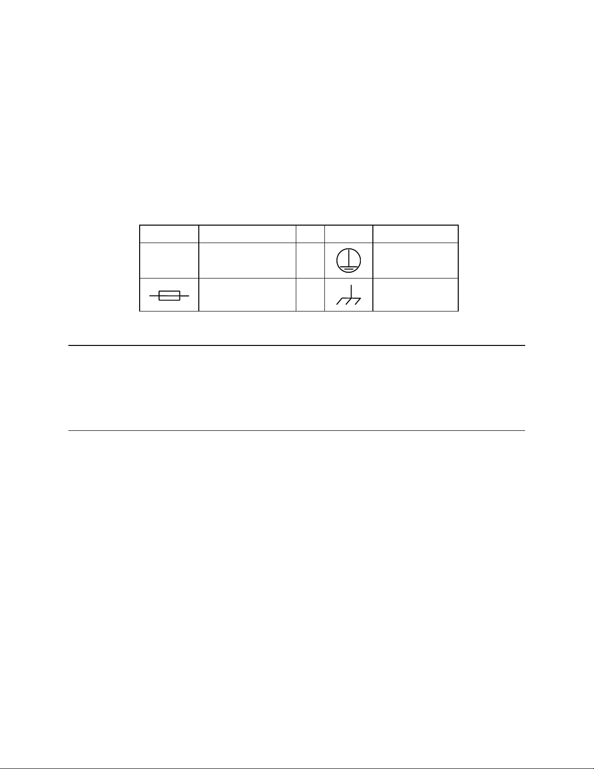
International Symbols:
Symbol Definition Symbol Definition
~
Alternating Current
Fuse
Telecommunications Terminal Equipment Directive
In accordance with the Telecommunications Terminal Equipment Directive 91/263/EEC,
this equipment should not be directly connected to the Public Telecommunications
Network.
EMC (Electromagnetic Compatibility)
In accordance with European Directive 89/336/EEC, the SNM-1010L Modem has been
shown, by independent testing, to comply with the following standards:
Emissions: EN 55022 Class B - Limits and methods of measurement of radio
interference characteristics of Information Technology Equipment.
(Also tested to FCC Part 15 Class B)
Immunity: EN 50082 Part 1 - Generic immunity standard, Part 1: Domestic,
commercial and light industrial environment.
Protective Earth
Chassis Ground
x
Page 13

SDM-2020 Satellite Modulator Revision 7
Preface MN/SDM2020M.IOM
Additionally, the SDM-2020 Satellite Modulator has been shown to comply with the
following standards:
EN 61000-3-2 Harmonic Currents Emission
EN 61000-3-3 Voltage Fluctuations and Flicker
EN 61000-4-2 ESD Immunity
EN 61000-4-4 EFT Burst Immunity
EN 61000-4-5 Surge Immunity
EN 61000-4-6 RF Conducted Immunity
EN 61000-4-8 Power frequency Magnetic Field Immunity
EN 61000-4-9 Pulse Magnetic Field Immunity
EN 61000-4-11 Voltage Dips, Interruptions, and Variations Immunity
EN 61000-4-13 Immunity to Harmonics
In order that the Modem continues to comply with these standards, observe
the following instructions:
IMPORTANT
• Connections to the transmit and receive IF ports (BNC female connectors) should
be made using a good quality coaxial cable - for example RG58/U (50 Ω or
RG59/U (75 Ω).
• All 'D' type connectors attached to the rear panel must have back-shells that
provide continuous metallic shielding. Cable with a continuous outer shield
(either foil or braid, or both) must be used, and the shield must be bonded to the
back-shell.
• The equipment must be operated with its cover on at all times. If it becomes
necessary to remove the cover, the user should ensure that the cover is correctly
re-fitted before normal operation commences
xi
Page 14
SDM-2020 Satellite Modulator Revision 7
Preface MN/SDM2020M.IOM
European EMC Directive
In order to meet the European Electro-Magnetic Compatibility (EMC) Directive
(EN55022, EN50082-1), properly shielded cables for DATA I/O are required. More
specifically, these cables must be shielded from end-to-end, ensuring a continuous
ground shield.
The following information is applicable for the European Low Voltage Directive
(EN60950):
<HAR> Type of power cord required for use in the European Community.
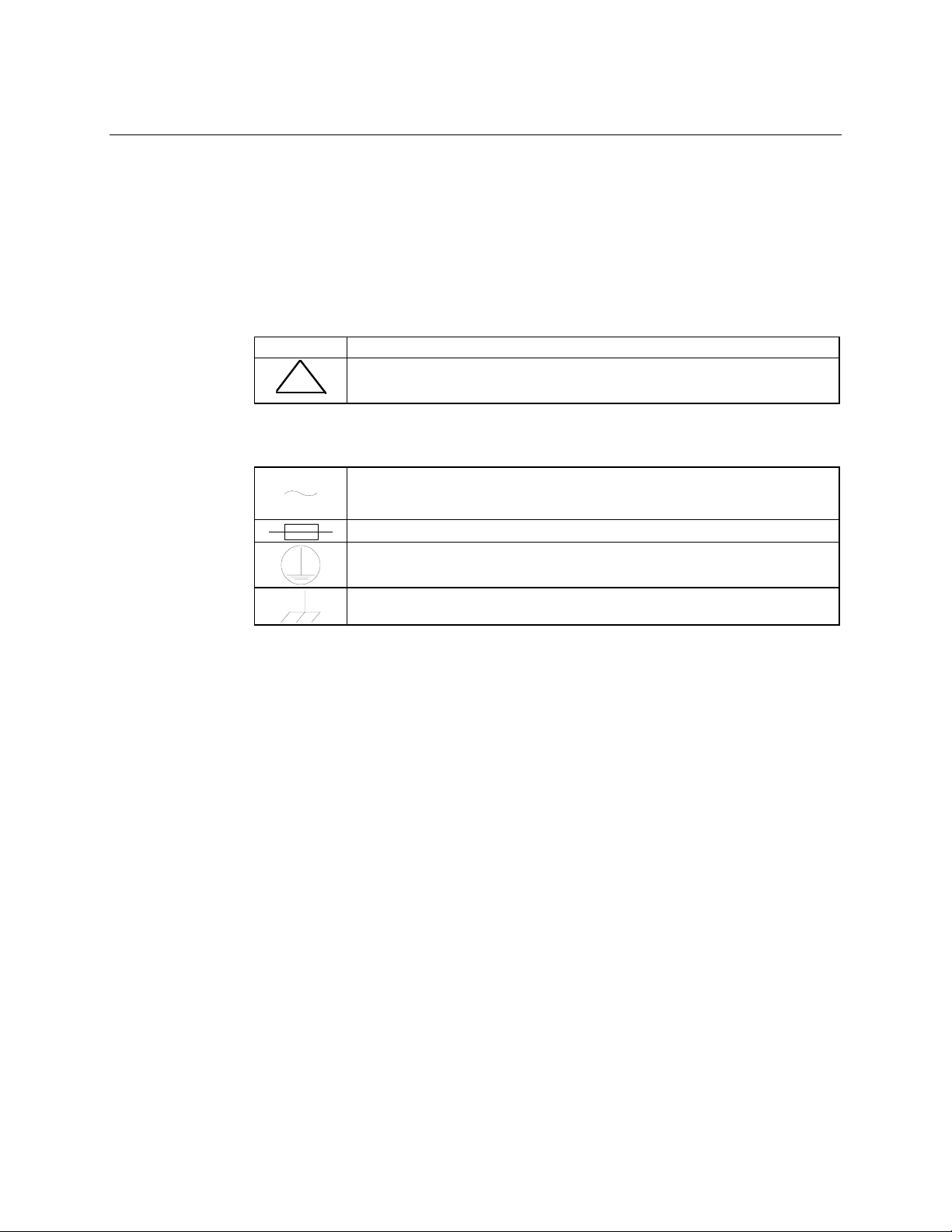
CAUTION: Double-pole/Neutral Fusing
!
International Symbols:
ACHTUNG: Zweipolige bzw. Neutralleiter-Sicherung
Alternating Current.
Fuse.
Safety Ground.
Chassis Ground.
Note: For additional symbols, refer to “Cautions and Warnings” listed earlier in this
preface.
xii
Page 15

SDM-2020 Satellite Modulator Revision 7
Preface MN/SDM2020M.IOM
Warranty Policy
This Comtech EF Data product is warranted against defects in material and workmanship
for a period of two year from the date of shipment. During the warranty period, Comtech
EF Data will, at its option, repair or replace products that prove to be defective.
For equipment under warranty, the customer is responsible for freight to Comtech EF
Data and all related custom, taxes, tariffs, insurance, etc. Comtech EF Data is responsible
for the freight charges only for return of the equipment from the factory to the customer.
Comtech EF Data will return the equipment by the same method (i.e., Air, Express,
Surface) as the equipment was sent to Comtech EF Data.
Limitations of Warranty
The foregoing warranty shall not apply to defects resulting from improper installation or
maintenance, abuse, unauthorized modification, or operation outside of environmental
specifications for the product, or, for damages that occur due to improper repackaging of
equipment for return to Comtech EF Data.
No other warranty is expressed or implied. Comtech EF Data specifically disclaims the
implied warranties of merchantability and fitness for particular purpose.
Exclusive Remedies
The remedies provided herein are the buyer's sole and exclusive remedies. Comtech EF
Data shall not be liable for any direct, indirect, special, incidental, or consequential
damages, whether based on contract, tort, or any other legal theory.
Disclaimer
Comtech EF Data has reviewed this manual thoroughly in order that it will be an easy-touse guide to your equipment. All statements, technical information, and
recommendations in this manual and in any guides or related documents are believed
reliable, but the accuracy and completeness thereof are not guaranteed or warranted, and
they are not intended to be, nor should they be understood to be, representations or
warranties concerning the products described. Further, Comtech EF Data reserves the
right to make changes in the specifications of the products described in this manual at any
time without notice and without obligation to notify any person of such changes.
If you have any questions regarding your equipment or the information in this manual,
please contact the Comtech EF Data Network Customer Support Department.
xiii
Page 16

SDM-2020 Satellite Modulator Revision 7
Preface MN/SDM2020M.IOM
This page is intentionally blank.
xiv
Page 17
SDM-2020
R
X
Satellite
Modulator
1.1 OVERVIEW
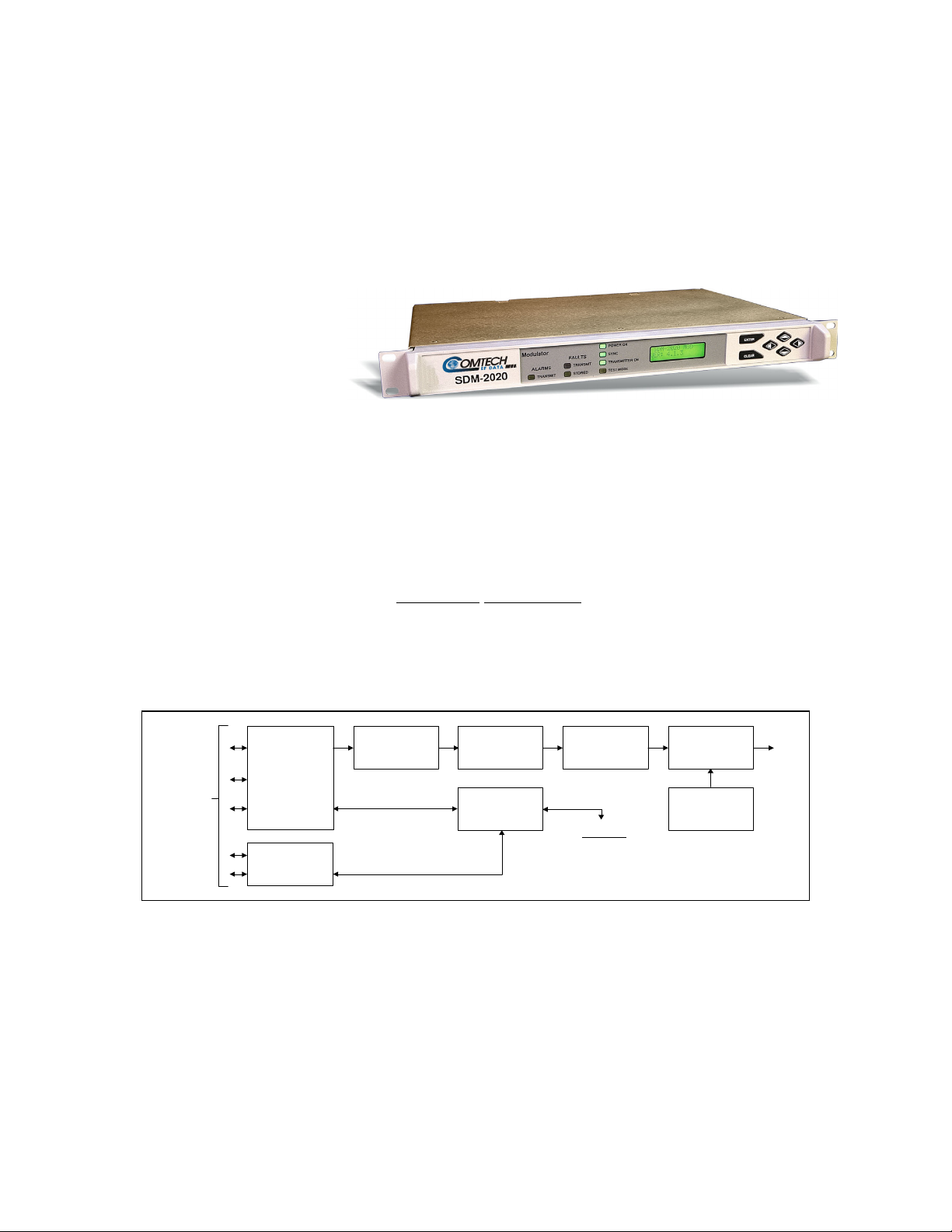
The SDM-2020 is a programmable, variable-rate satellite modulator used for digital
video and high-speed data applications. The modulator supports open network modes
compliant with the ETSI EN 300 421
Broadcasting (DVB) by satellite.
Chapter 1. INTRODUCTION
/prEN 301 210 specification for Digital Video
A general block diagram for the modulator is shown in Figure 1-1.
DATA FILTER
AND
MODULATOR
SYNTHESIZERM&C
T
IF
USER
INTERFACE
PLUG-IN
DATA
INTERFACE
REMOTE PORT
AND FAULTS
SYNCH
AND
RANDOMIZE
RS CODER
AND
INTERLEAVER
VITERBI CODER
AND
MAPPING
TO/FROM
SYNCH AND RANDOMIZE
RS CODER AND INTERLEAVER
VITERBI CODER AND MAPPI NG
DATA FILTER AND MODULATOR
SYNTHESIZE
Figure 1-1. Modulator Block Diagram
1-1
Page 18

SDM-2020 Satellite Modulator Revision 7
Introduction MN/SDM2020M.IOM
The modulator utilizes a plug-in data interface module installed in the rear of the chassis.
The data interface module provides flexible adaptation to the various physical and
electrical interfaces found in the communications industry.
The modulator utilizes Fully Accessible System Topology (FAST), Comtech EF Data’s
new feature for immediate implementation of different options through the user interface
keypad. FAST enable on-location upgrades of the operating feature set—in the rack—
without removing a unit from the setup. This feature employs a unique access code to
enable configuration of the available hardware. The access code can be purchased at any
time from Comtech EF Data. Once obtained, the access code is entered into the unit
through the front panel keypad or the rear remote port. When service requirements
change, the modulator can be upgraded to meet the new requirements within minutes
after confirmation by Comtech EF Data.
The data rate of the modulator is programmable from 1.5 to 100 Mbit/s depending upon
the data interface and the maximum symbol rate is 37.5 Msym/s. The minimum symbol
rate is limited by the minimum 1.5 Mbit/s data rate. Modulation formats include QPSK,
8PSK, and 16QAM. Operation is based upon the DVB/DBS standard for QPSK and
8PSK.
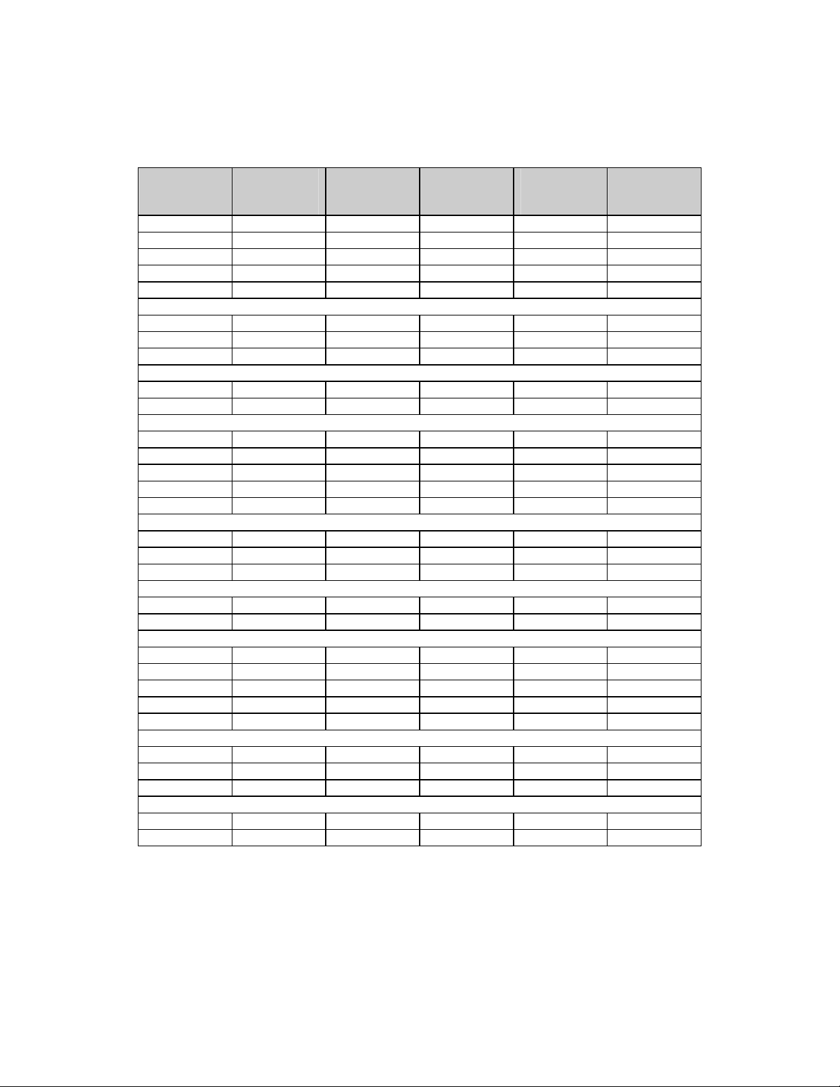
Table 1-1 lists the minimum and maximum data and symbol rates for each code rate. See
the specifications section for the maximum data rate limits by framing types.
1-2
Page 19
SDM-2020 Satellite Modulator Revision 7
Introduction MN/SDM2020M.IOM
Table 1-1. Minimum/Maximum Data and Symbol Rates
Code Rate
QPSK 1/2 188 1,500,000 34,558,823 1,627,659 37,500,000
QPSK 2/3 188 1,500,000 46,078,431 1,220,744 37,500,000
QPSK 3/4 188 1,500,000 51,838,235 1,085,106 37,500,000
QPSK 5/6 188 1,500,000 57,598,039 976,595 37,500,000
QPSK 7/8 188 1,500,000 60,477,941 930,091 37,500,000
8PSK 2/3 188 1,500,000 69,117,647 813,829 37,500,000
8PSK 5/6 188 1,500,000 86,397,059 651,063 37,500,000
8PSK 8/9 188 1,500,000 92,156,863 610,372 37,500,000
16QAM 3/4 188 1,500,000 92,156,863 542,553 33,333,333
16QAM 7/8 188 1,500,000 92,156,863 465,045 28,571,428
QPSK 1/2 204 1,500,000 37,500,000 1,500,000 37,500,000
QPSK 2/3 204 1,500,000 50,000,000 1,125,000 37,500,000
QPSK 3/4 204 1,500,000 56,250,000 1,000,000 37,500,000
QPSK 5/6 204 1,500,000 62,500,000 900,000 37,500,000
QPSK 7/8 204 1,500,000 65,625,000 857,142 37,500,000
8PSK 2/3 204 1,500,000 75,000,000 750,000 37,500,000
8PSK 5/6 204 1,500,000 93,750,000 600,000 37,500,000
8PSK 8/9 204 1,500,000 100,000,000 562,500 37,500,000
16QAM 3/4 204 1,500,000 100,000,000 500,000 33,333,333
16QAM 7/8 204 1,500,000 100,000,000 428,571 28,571,428
QPSK 1/2 None (187) 1,500,000 34,375,000 1,636,363 37,500,000
QPSK 2/3 None (187) 1,500,000 45,833,333 1,227,272 37,500,000
QPSK 3/4 None (187) 1,500,000 51,562,500 1,090,909 37,500,000
QPSK 5/6 None (187) 1,500,000 57,291,667 981,818 37,500,000
QPSK 7/8 None (187) 1,500,000 60,156,250 935,064 37,500,000
8PSK 2/3 None (187) 1,500,000 68,750,000 818,181 37,500,000
8PSK 5/6 None (187) 1,500,000 85,937,500 654,545 37,500,000
8PSK 8/9 None (187) 1,500,000 91,666,667 913,636 37,500,000
16QAM 3/4 None (187) 1,500,000 91,666,667 545,454 33,333,333
16QAM 7/8 None (187) 1,500,000 91,666,667 467,532 28,571,428
Framing
Type
Minimum
Data Rate
(bps)
Maximum
Data Rate
(bps)
Minimum
Symbol Rate
(sym/s)
Maximum
Symbol Rate
(sym/s)
1-3
Page 20

SDM-2020 Satellite Modulator Revision 7
Introduction MN/SDM2020M.IOM
The modulator incorporates concatenated error correction coding for improved signal
quality. With concatenated coding, an outer Reed-Solomon Codec is used in tandem with
an inner Viterbi or trellis-type Codec. The Reed-Solomon coding is DVB (based on 204,
188, t=8 type code), while the Viterbi and trellis codes are based upon a constraint length
K = 7 convolutional coding. This combination significantly reduces the required
operating power of the satellite system.
The modulator is a complete, self-contained unit in a standard, one-unit (1U) 19-inch
(48.26 cm) rack-mountable enclosure. It includes a backlit LCD display and a standard
Comtech EF Data 6-button keypad for user control.
A status and control port (available through a 9-pin D connector at the rear of the chassis)
provides either serial EIA-232 or EIA-485 for remote control applications. A second rearpanel 9-pin D connector provides fault/alarm status.
The unit is designed to meet stringent safety and RF emissions standards, including CE
Mark certification.
1.2 ASSEMBLIES
1.2.1
MODULATOR
The modulator consists of the assemblies listed in Table 1-2.
Table 1-2. Comtech EF Data Module Part Numbers
Part Number Description
PL/8200-1 SDM-2020 Top Assembly
PL/3995-39
PL/5612 Modulator Assembly
PL/3995-40
KT/8200 Chassis Assembly
IF Module, 75Ω
IF Module, 50Ω
1-4
Page 21

SDM-2020 Satellite Modulator Revision 7
Introduction MN/SDM2020M.IOM
1.2.2 DATA INTERFACES
Data interface assemblies are listed in Table 1-3.
Table 1-3. Comtech EF Data Part Numbers for Data Interface Modules
Part Number Description
PL/5805 RS422 Data Serial/Parallel Data Interface
PL/5806-2 ECL/HSSI Serial Data Interface (For TX only)
PL/5807 ASI/RS422 (Asynchronous Serial Interface and Serial Data Interface)
PL/5814 LVDS-DVB Serial/Parallel Data Interface
PL/6168 G.703 Data Interface
PL/6175-2 SMPTE 310M Data Interface
PL/8160 ASI/LVDS Interface
The data interface is a plug-in module. As new interfaces are developed, the related
information will be added to this manual. All data interfaces are safety rated to SELV
(IEC 950, Paragraph 1.2.8.5).
For additional data interface availability, contact Comtech EF Data Customer Support.
1.2.3 FAST OPTIONS
Certain options are enabled using Comtech EF Data’s FAST feature. The software and
other requirements for the FAST options are also listed in this appendix. Options include:
• 8PSK
• 16QAM
• Original Equipment Manufacture “Liquid Crystal Display” (OEM
LCD)
1-5
Page 22

SDM-2020 Satellite Modulator Revision 7
Introduction MN/SDM2020M.IOM
This page is intentionally left blank.
1-6
Page 23

Chapter 2. SPECIFICATIONS
2.1 SPECIFICATIONS
2.1.1 GENERAL SPECIFICATION
Table 2-1. General Specifications
Parameter Specification
Transmission Format QPSK per EN 300 421
8PSK per prEN 301 210, optional
16QAM per prEN 301 210, optional
Data Rate/Symbol Rate 1.5 to 100 Mbit/s, in 1 bit/s steps, depending upon symbol rate and data interface.
Refer to Chapter 1 for the appropriate Data Rate.
Equivalent Serial Data Rate at
96 pin DIN
Framing 187
188
204
Data Rate Tolerance
Modulation Type and Inner
Code Rate
Outer Code Rate
(Reed-Solomon)
Interleaving Depth 12, per EN 300 421 and prEN 301 210
Spectral Shaping
Framing
Data Rate = SR x m x CRv x (187/204), ≤ 100 Mbit/s
Data Rate = SR x m x CRv x (188/204), ≤ 100 Mbit/s
Data Rate = SR x m x CRv x (204/204), ≤ 100 Mbit/s
m = 2 QPSK, 3 8PSK, 4 16QAM
CRv = Viterbi/trellis code rate
CRrs = Reed-Solomon code rate
Programmed rate ± 100 ppm
QPSK: 1/2, 2/3, 3/4, 5/6, 7/8
8PSK: 2/3, 5/6, 8/9
16QAM: 3/4, 7/8
RS (204, 188, t = 8)
Square-root raised cosine, α = 0.35 per EN 300 421 and prEN 301 210
2-1
Page 24

SDM-2020 Satellite Modulator Revision 7
Product Data Specification MN/SDM2020M.IOM
Table 2-1. General Specifications (Continued)
Parameter Specification
Energy
Dispersal
Spectral Sense Normal or Inverted
Front Panel
Interface
M&C Interface Programmable selection for EIA-232, 2-wire EIA-485 or 4-wire EIA-485, 9-pin D female connector,
Fault/Alarm
Interface
Status Relays
Max. Current
Voltage
Unit Cooling Exhaust fan located on the left of the unit when viewed from the rear.
Rated AC
Power Input
Power
Distribution
System
EN 300 421 and prEN 301 210 , or None
Keypad + LCD with back lighting
serial, ASYNC
Form C, 9-pin D, female connector
TX Fault, TX Alarm, Common Equipment
< 30 VAC, 42.4 Vpk-pk, or 60 VAC
100 to 240 VAC, 50 to 60 Hz; 1.0A at 100 VAC or 0.5A at 240 VAC. Connection universal type IEC
320.
40W typical, 65W maximum.
Note: This equipment is fitted with a wide-ranging power supply that will operate at +6% to –10% of
the rated voltage range.
IEC 950, Paragraph 1.6.5.
Type TN only (EN 60950 Paragraph 1.2.12.1).
Note: The equipment shall not be used with single-phase three-wire and PE.
Connection to
Supply
Power Supply
Fuses
Class of
Equipment
Power Supply
Hold-up
DC Power
Input optional
CE
Compliance
Pluggable equipment Type A (EN 60950, Paragraph 1.2.5).
Note: Equipment which is intended for connection to the building power supply wiring via a
nonindustrial plug and socket outlet or a nonindustrial appliance coupler or both.
Double pole fused.
Fuse type 20mm 2A T-type HBC (T2A H250V)
(IEC 127, Sheet V, approved and UL recognized)
Class 1 Equipment (EN60950, Paragraph 1.2.4): electric shock protection by basic insulation and
protective earth.
16 ms minimum at 120 VAC
78 ms minimum at 240 VAC
42 to 56 VDC. 40W typical, 65W maximum.
Required
2-2
Page 25

SDM-2020 Satellite Modulator Revision 7
Product Data Specification MN/SDM2020M.IOM
2.1.2 ENVIRONMENTAL AND PHYSICAL SPECIFICATION
Table 2-2. Environmental and Physical Specifications
Parameter Specification
Physical:
Size
Weight
Environmental:
Temperature
Humidity
1 U rack mount, IEC 297, DIN41494 Type.
19W x 1.75H x 14D inch
(48.26W x 4.44H x 35.56D cm)
< 15 lbs. (< 7.0 kg.)
0 to +50°C (32 to 122°F), Operating
-40 to +70°C (-40 to 158°F), Storage
< 95%, non-condensing
Note: Power supply has an operating range of 85 to 264 VAC, 47 to 63 Hz,
universal type per manufacturer’s published data sheet.
2-3
Page 26

SDM-2020 Satellite Modulator Revision 7
Product Data Specification MN/SDM2020M.IOM
2.1.3 MODULATOR SPECIFICATIONS
Table 2-3. Modulator Specifications
Modulator Characteristics
TX IF Output 50 to 90 and 100 to 180 MHz, 2.5 kHz steps
-20 to +5 dBm in 0.1 dB steps
(± 0.5 dB accuracy over operating temperature range)
TX IF Impedance
Optional TX IF Impedance
IF Output Connector BNC, female
TX Spurious:
Modulated Carrier
TX Spurious:
Unmodulated Carrier
TX Carrier Isolation -60 dBm maximum when TX carrier = OFF
AC Line Spurious -36 dBc maximum
IF and Data Frequency Stability
TX Carrier Phase Noise
(Single Sideband)
-66 100 Hz
-76 1 kHz
-86 10 kHz
75Ω, 18 dB return loss minimum
50Ω, 18 dB return loss minimum
-55 dBc minimum in a 4 kHz bandwidth relative to unmodulated carrier power for
all modulated carrier power levels. The measurement bandwidth is 5 to 500 MHz
excluding ± 1.4 times the symbol rate about the carrier frequency.
-55 dBc minimum in a 4 kHz bandwidth, TX power level is
≤ -5 dBm. The measurement bandwidth is 5 to 500 MHz.
± 10 ppm
Max dBc/Hz
Offset from Carrier Frequency
-96 100 kHz
-96 1 MHz
Amplitude and Phase Imbalance
Carrier Null (Suppression) 30 dB, minimum
Sideband Suppression 30 dB minimum, when generating a single side band
Group Delay 4 ns peak-to peak maximum to 18.75 MHz, within EN 300 421 and prEN 301 210
I/Q Delay Matching 0.5 ns difference maximum to 18.75 MHz.
Jitter Tolerance Main Card Meets ITU-T G.823 (3/93) and ITU-T G.824 (3/93)
Jitter Transfer
2-4
± 0.2 dB, maximum
± 2°, maximum
carrier (Offset Mode)
except T1 (1.544 Mbit/s) and E1 (2.048 Mbit/s), which requires a G.703 data interface.
< 0.5 dB peaking up to the cutoff frequency, -20 dB per decade beyond cutoff.
Nominal 3 dB cutoff is 10 Hz except E3 (34.368 Mbit/s), which is 100 Hz.
Page 27

SDM-2020 Satellite Modulator Revision 7
Product Data Specification MN/SDM2020M.IOM
Table 2-4. Modulator Specifications (Continued)
Monitor & Control Characteristics
Asynchronous Serial Interface EIA-485 (2-/4-wire), or EIA-232
Baud Rate 300, 600, 1200, 2400, 4800, 9600, or 19200 bps
Serial Format ASCII
Data Bits 7 bits with odd/even parity
8 bits with no parity
Stop Bits 2
Parity Odd, Even, or None
Remote Port Addressing Range: 1 to 255
Controlled Items:
Data
Modulation, Coding Modulation Type: QPSK, 8PSK, 16QAM
Carrier TX IF Frequency
Test (Where Applicable) Pure Carrier
General Date and Time
Status All other configuration items
Faults Loss of Clock, or Out of Tolerance
Configuration Retention Non-volatile
Store Configurations 10 stored with recall.
Data Rate
Symbol Rate
Energy Dispersal (Scrambler) On/Off (Test Mode)
Differential Encoder (On/Off)
Framing Type (None, 188, 204)
Clock and Data Phase (Normal/Inverted)
Code Rate (Viterbi/trellis)
Spectral Mask, DVB
TX Output (On/Off)
TX Output Power Level
Spectral Inversion: Normal/Inverted
Dual Carrier (Carrier Null)
Offset Carrier (Single Sideband)
Data Loopback (Where Applicable)
LED Test
Scrambler (On/Off)
Reset
2047 Pattern (into payload)
Data Loopback
Software/Firmware Version and Unit Identification
Display Contrast
Data Stable, all 1s (AIS), or all 0s
Loss of Synchronization
IF Synthesizers
2-5
Page 28
SDM-2020 Satellite Modulator Revision 7
14.0
Product Data Specification MN/SDM2020M.IOM
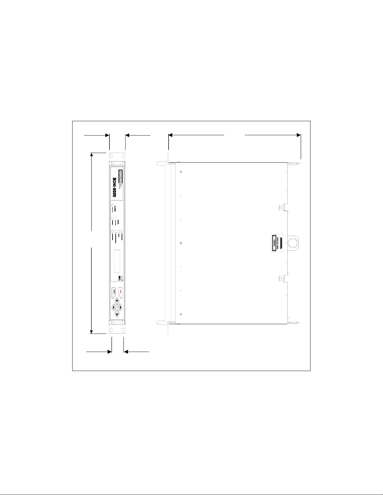
2.2 DIMENSIONAL ENVELOPE
Refer to Figure 2-1 for modulator dimensional measurements. All dimensions are listed
in inches, centimeters are shown in parentheses.
19.0
(48.26)
1.75
(4.45)
(35.56)
1.25
(3.18)
Table 2-5. Dimensional Envelope of Units Prior to September 1, 1999
2-6
Page 29
SDM-2020 Satellite Modulator Revision 7
Product Data Specification MN/SDM2020M.IOM
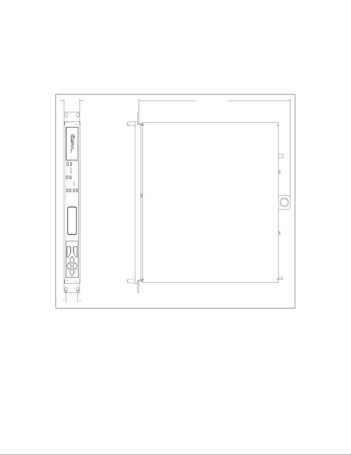
As of September 1, 1999, SDM-2020 Modulator production units will incorporate a new and EMI
improved chassis. The new chassis is longer and includes the new Comtech EF Data logo. All
units returning from the field may have the new chassis installed if warranted by the repair. See
Figure 2-2.
1.70 [4.32]
SDM-2020
TRANSMI T STORED
RANSMIT TRANSMITTER O N
SYNC
TESTMODE
POWERON
16.12 [40.94]
1.25 [3.18]
Table 2-6. Dimensional View for Units with Improved Chassis
2-7
Page 30

SDM-2020 Satellite Modulator Revision 7
Product Data Specification MN/SDM2020M.IOM
This page is intentionally left blank
.
2-8
Page 31

The equipment contains parts and assemblies sensitive to
damage by Electrostatic Discharge (ESD). Use ESD precautionary
CAUTION
procedures when touching, removing, or inserting PCBs.
3.1 UNPACKING
The modulator and manual are packaged in pre-formed, reusable, cardboard cartons
containing foam spacing for maximum shipping protection.
Do not use any cutting tool that will extend more than 1 inch
(2.54 cm) into the container. This can cause damage to the
CAUTION
To remove the modulator:
modulator.
Chapter 3. INSTALLATION
Cut the tape at the top of the carton indicated by OPEN THIS END
1
Remove the cardboard/foam space covering the modulator
2
Remove the modulator, manual, and power cord from the carton
3
Save the packing material for storage or reshipment purposes
4
Inspect the equipment for any possible damage incurred during shipment
5
Check the equipment against the packing list to ensure the shipment is correct
6
Refer to Section 3.2 for installation instructions
7
3-1
Page 32

SDM-2020 Satellite Modulator Revision 7
Installation MN/SDM2020M.IOM
3.2 INSTALLATION
A complete modulator consists of the SDM-2020 main unit and an optional plug-in data
interface. The modulator is shipped with the data interface installed in the unit. Changing
a data interface is easily accomplished in the field and does not require disassembly of
the main unit.
Refer to applicable chapters for information on removing and installing data interface
modules.
Install the modulator as follows:
Optional: Install the mounting bracket in equipment rack (Figure 3-1). Install and
1
tighten the bracket bolts.
Loosen the screw with flat washer located on the left-side of modem chassis.
2
Mount the modem chassis into the equipment rack and slide the screw with flat
washer through the slot of the mounting bracket. Tighten the screw sufficiently to
allow the modem chassis to slide in the bracket.
Connect the cables to the proper locations on the rear panel.
3
Observe the modulator. The modulator powers ON automatically when the
4
primary power connection is made (plugged in). Before plugging in the modulator,
become familiar with the front panel operation as described in Chapter 5.
Note: If there is any problem with the installation, contact Comtech EF Data’s Customer
Support Department: service@comtechefdata.com
3-2
Page 33

SDM-2020 Satellite Modulator Revision 7
U
Installation MN/SDM2020M.IOM
Equipment
Rack
Mounting
Rail
#10 Socket head
*
screw
BRACKET
*
BOLTS
Support
*
Bracket
* Note: Components of mounting kit KT/6228-1
ID
Figure 3-1. Installation of the Optional Mounting Bracket, KT/6228-1
3-3
Page 34

SDM-2020 Satellite Modulator Revision 7
Installation MN/SDM2020M.IOM
3.2.1 CABLING
The following cabling instructions are generic. Comtech EF Data realizes
there are several different cabling applications for the SDM- 2020
IMPORTANT
Modulator, however, this manual cannot illustrate or described the
various installation configurations.
Back of
Rack
J1 J2
R
F
E
A
100-240V~
M
U
1.5A 50-60Hz
O
L
T
T2A, 250V
T
6
E
J3
ECL / HSSI INTERFACE
J21J21
M
M
O
N
I
RF 1
T
O
R
Lengend
1
3
4
5
2
Up Converter
Router
Figure 3-2. Rear View of SDM-2020M Rack Installed
Item # Cable From To Comment
1 Prime Power Cord I.E.C Rack Power Source 3-Pong Power Cord
2 Remote J1 EXT PC Terminal 9-pin D
3 Fault J2 EXT PC Terminal 9-pin D
4
Data Interface,
Customer Select
Interface
5 IF Output CP1
6 Ground #10-32 Stud Rack Equipment
JX SERIAL
JX PARALLEL
JX AUX
Cissco router or
equivalent
Upconverter or
RF Terminal
Refer to Chapter 6
Data Interfaces
BNC
Prime Power Cord
Remote Ribbon Cable
Fault Cable
Data Interface
IF Output
Ground
3-4
Page 35

SDM-2020 Satellite Modulator Revision 7
Installation MN/SDM2020M.IOM
3.2.2 DATA INTERFACES
The data interface is a removable, plug-in module that provides a terrestrial connection to
the modulator. An interface consists of a Printed Circuit Board (PCB) attached to a
faceplate. The faceplate contains connectors appropriate for the interface type, and two
captive mounting screws.
Appendix C describe the various data interfaces. After a different interface type has been
installed, the modulator recognizes the change upon power up, and defaults to valid
parameters for the new interface.
To avoid damaging the modulator, always disconnect the power before
removing or installing a data interface.
CAUTION
Figure 3-3 is an example of a typical data interface.
J3 PARALLEL J4 SERIAL J5 AUX
Figure 3-3. Typical Data Interface Module
3-5
Page 36

SDM-2020 Satellite Modulator Revision 7
Installation MN/SDM2020M.IOM
3.2.2.1 DATA INTERFACE REMOVAL
Disconnect power from the modulator.
1
2
Use a Phillips screwdriver to loosen the two captive screws on the faceplate
of the data interface.
Grasp the data interface by the faceplate handle.
3
Carefully pull the data interface out of the slot.
4
3.2.2.2 DATA INTERFACE INSTALLATION
Disconnect power from the modulator.
1
Grasp the data interface by the faceplate handle.
2
Locate the opening at the rear of the modulator.
3
Carefully align the data interface with the card guides inside the modulator and
4
insert the data interface into the opening.
Push the data interface firmly into the slot, ensuring a good connection.
5
Align the captive screws located on the faceplate with the holes on the modulator
6
rear panel.
7
Use a Phillips screwdriver to tighten the screws.
3-6
Page 37

Chapter 4. EXTERNAL CONNECTIONS
4.1 EXTERNAL CONNECTIONS
The connectors for the main unit are shown in Figure 4-1 and identified in Table 4-1.
The connectors for each plug-in data interface are described in their applicable chapters.
PRIME
POWER
GROUND
FUSE HOLDER
Remote J1 9-pin D Female Remote control (M&C)
Fault J2 9-pin D Female Faults status relays
IF Output CP1 BNC-Female Transmit IF output
Prime Power I.E.C Standard AC Power Input
GND None #10-32 Stud Chassis Ground
Data Interface Connectors See applicable chapter.
J1 REMOTE
Name Ref. Desig. Type Function
J2 FAULT
Figure 4-1. Rear Panel
Table 4-1. Rear Panel Connectors
DATA INTERFACE CONNECTIONS CP1 TX-IF
4-
1
Page 38

SDM-2020 Satellite Modulator Revision 7
External Connections MN/SDM2020M.IOM
4.1.1 REMOTE CONNECTOR AND PINOUT (J1)
The remote control connection is a 9-pin female D connector located on the rear panel of
the modulator. Screw locks are provided for mechanical security of the mating connector.
The remote connector provides a means for issuing commands and determining the unit
status. This connector provides EIA-232, EIA-485 (2-wire), and EIA-485 (4-wire)
operation. The communications protocol and the control and status commands are
described in Appendix A.
Table 4-2. Remote Control Connector Pinout (J1)
Remote Control Connector (J1) Pinout
EIA-232C EIA-485 (2) EIA-485 (4)
Signal Type Signal Type Signal Type Pin #s
GND GND GND GND GND GND 1
RXD O N/A N/A N/A N/A 2
TXD I N/A N/A N/A N/A 3
N/A N/A +RX/+TX I/O +TX I 4
GND GND -RX/-TX I/O -TX I 5
DSR O N/A N/A N/A N/A 6
RTS I N/A N/A N/A N/A 7
CTS O +RX/+TX I/O +RX O 8
N/A N/A -RX/-TX I/O -RX O 9
4-2
Page 39

SDM-2020 Satellite Modulator Revision 7
External Connections MN/SDM2020M.IOM
4.1.2 FAULT CONNECTOR (J2)
The fault interface connection is a 9-pin female D connector located on the rear panel of the
modulator. Screw locks are provided for mechanical security on the mating connector.
The fault connector provides FORM-C contact closures for fault reporting. The two
FORM-C summary fault contacts are Modulator and Common Equipment. To obtain a
system summary fault, connect all of the FORM-C contacts in parallel.
Table 4-3. Faults Status Relays Connector Pinout (J2)
Signal
Function
Common Equipment Fault CE_NO
Modulator Fault MOD_NO
Modulator Alarm ALM_NO
Name Pin # Type
1
CE_COM
CE_NC
MOD_COM
MOD_NC
ALM _COM
ALM _NC
2
3
4
5
6
7
8
9
FC
FC
FC
FC
FC
FC
FC
FC
FC
Note: A connection between the common (COM) and normally open (NO) contacts
indicates no fault.
4.1.3 TRANSMIT IF OUTPUT CONNECTOR (CP1)
CP1 is a BNC connector for the TX IF signal output. The output impedance is 75Ω
(50Ω optional). The output is a modulated carrier between 50 and 180 MHz.
Pins Connected
Fault/
Alarm OK
2-3 1-2 2-3
5-6 4-5 5-6
7-8 8-9 8-9
Power
OFF
4.1.4 AC POWER
This unit shall be operated from the type of power source indicated on
the marking label. If power source is unknown, contact the local power
company. Damage to the unit may be the result.
4-3
Page 40

SDM-2020 Satellite Modulator Revision 7
External Connections MN/SDM2020M.IOM
Type TN System Only (EN 60950, Paragraph 1.2.12.1) - Power Distribution System:
Power distribution system having one point directed toward the earth, the exposed
conductive parts of the installation being connected to that point by protective earth
conductors. This equipment shall not be used with single-phase three-wire (PE, TT, or IT)
type power distribution system.
The A/C power is supplied to the modulator by a standard, detachable, non-locking,
3-prong power cord. The cord connects to a fused IEC 320-type power receptacle.
Internal to the unit, color-coded wiring is used in the A/C mains as follows:
Live
Neutral
Ground
Note: Since the equipment is not fitted with an ON/OFF switch, the A/C socket-outlet shall be
installed near the equipment and shall be easily accessible (EN 60950 1.7.2).
IMPORTANT
4.1.5 FUSE DATA
Fuse Type:
Littlefuse 215002 5 x 20 mm
UK Europe USA
(BS 1363) (CEE 7/7) (NEMA 5-15P)
Brown Brown Black
Blue Blue White
Green/Yellow Green/Yellow Green
Before replacing the fuses in the A/C input connector, disconnect
the equipment from the power supply. Failure to do so may expose
hazardous voltages. Unplug the equipment from the local power
supply socket.
Fuse:
T2A H250V
Time Delay, 2A, High Breaking Capacity
Double Pole
(Approved to IEC 127, Sheet V and Underwriters Laboratories)
Refer to input power requirements as specified in Chapter 2.
Replacing a fuse
Remove the fuseholder on the back of the IEC 320 style A/C input connector (Figure 4-1).
1
Replace fuse with same or equivalent rated part and/or model number.
2
4-4
Page 41

SDM-2020 Satellite Modulator Revision 7
External Connections MN/SDM2020M.IOM
4.1.6 DC POWER (OPTIONAL)
DC power is an available option. Contact Comtech EFData’s Customer Support for
further assistance.
4.1.7 GROUND (GND) OR EARTH
A #10-32 stud is available on the rear panel for the purpose of connecting a common
chassis ground among all of the equipment.
Note: A safety ground is provided through the AC power connector.
4.1.8 LITHIUM BATTERY REPLACEMENT
Danger of explosion if battery is incorrectly replaced. Replace only with
the same or equivalent type recommended by the manufacturer. Dispose
CAUTION
4.2 PROPER OPERATIONS FOR EMISSIONS (CE)
To ensure compliance with the EMC Directive 89/336/EEC, properly shielded cables for
Data I/O shall be used. These cables shall be doubled-shielded from end-to-end, ensuring
a continuous ground shield.
of used batteries according to the manufacturer’s instructions.
4-5
Page 42

SDM-2020 Satellite Modulator Revision 7
External Connections MN/SDM2020M.IOM
This page is intentionally left blank.
4-6
Page 43

5.1 FRONT PANEL
The modem front panel (Figure 5-1) enables control of modem configuration parameters
and displays the modem status.
Chapter 5. FRONT PANEL
OPERATIONS
Modulator
ALARMS
TRANSMIT
FAU LTS
TRANSMIT
STORED
POWER ON
SYNC
TRANSMITTER ON
TEST MODE
ENTER
CLEAR
Figure 5-1. Front Panel View
The front panel features include:
• 32-character, 2-line LCD display
• 6-button keypad for local control
• 7- LEDs to provide overall status at a glance
All functions are accessible at the front panel by entering one of six pre-defined Function
Select categories or levels:
• Configuration
• Monitor
• Faults/Alarms
• Stored Faults/Alarms
• Utility
5-1
Page 44

SDM-2020 Satellite Modulator Revision 7
Front Panel Operation MN/SDM2020M.IOM
5.2 LED INDICATORS
The seven LEDs on the front panel indicate:
• General modem summary faults
• Status
• Alarms
The indicators are defined in Table 5-1 as follows:
Table 5-1. LED Indicators
Name LED Description
Faults
Transmit Red A fault condition exists in the transmit chain.
Stored Yellow A fault has been logged and stored.
The fault may or may not be active.
Status
Power On Green Power is applied to the modem.
SYNC Green The modulator is synchronized to the data in the selected framing
mode. The LED is continuously On when the DVB Framing Type
is None.
Transmitter On Green Transmitter is currently On.
This indicator reflects the actual condition of the transmitter, as
opposed to be programmed condition.
Test Mode Yellow Flashes when the modem is in a test configuration.
Alarms
Transmit Yellow A transmit function is in an alarm condition.
5-2
Page 45

SDM-2020 Satellite Modulator Revision 7
Front Panel Operation MN/SDM2020M.IOM
5.3 FRONT PANEL KEYPAD
The keypad has an auto-repeat feature. If a key is held down for more than 1
second, the key action will repeat, automatically, at the rate of 15 keystrokes per
IMPORTANT
second. This is particularly useful when editing numeric fields, with many digits,
such as frequency or data rate.
The front panel keypad permits local operation of the modem. The keypad consists of six
keys (Figure 5-2).
ENTER
CLEAR
Figure 5-2. Keypad
Each key provides one or more logical functions. These functions are defined in the
following table.
ENTER
CLEAR
Left and Right
Diamond Keys
Top and Bottom
Diamond Keys
This key is used to select a displayed function or to execute a
modem configuration change.
This key is used to back out of a selection or to cancel a
configuration change which has not been executed using
[ENTER]. Pressing [CLEAR] generally returns the display to
the previous selection.
These keys are used to move to the next selection or to move
the cursor for certain functions.
Note: Throughout this chapter, [←] and [→] are used to
indicate left and right diamond keys.
These keys are used primarily to change configuration data
(numbers). At times, they are also used to move from one
section to another.
Note: Throughout this chapter, [↑] and [↓] are used to indicate
top and bottom diamond keys.
5-3
Page 46

SDM-2020 Satellite Modulator Revision 7
Front Panel Operation MN/SDM2020M.IOM
The modem responds by beeping whenever a key is pressed:
• A single beep indicates a valid entry and the appropriate action was taken
• A double beep indicates an invalid entry or a parameter is not available for
operation
.
5.4 MENU SYSTEM
Note: The menus show features and options that are not available. However, they are
shown to preserve the menu structure and reserve the structure for the future. This does
not imply an intent or obligation to add these features or options in the future.
Use the Main menu in Figure 5-3 as a quick reference for accessing the modem functions.
When the modem power is applied, the base level of the menu system displays the
sign-on message:
• Line 1 of the sign-on message is the modem model number and type.
• Line 2 is the version number of the firmware.
The main level of the menu system is Function Select. To access this level from the
sign-on message, press the [←] or [→] keys. From the Function Select menu; select one
of the functional categories:
• Configuration
• Monitor
• Faults/Alarms
• Stored Faults/Alarms
• Utility
Press [←] or [→] to move from one selection to another. When line 2 displays the desired
function, select that level by pressing [ENTER]. After entering the appropriate functional
level, press [←] or [→] to move to the desired function.
5-4
Page 47

SDM-2020 Satellite Modulator Revision 7
Front Panel Operation MN/SDM2020M.IOM
To view or change the modem’s configuration, enter the Configuration level from the
Function Select menu. Once in the Configuration menu, press [←] or [→] to scroll
through the Configuration menu selection:
• Modulator
• Demodulator
• Interface
• Save
• Recall
Press [ENTER] to select the desired Configuration menu option. To view the options for
the selected configuration parameters, press [←] or [→]. To change a configuration
parameter, press [ENTER] to begin the change process.
Press [↑] or [↓] to change the parameters. After the display represents the correct
parameters, press [ENTER] to execute the change. This action initiates the necessary
programming by the modem.
To undo a parameter change prior to execution, press [CLEAR].
Notes:
1. Figure 5-3 list the front panel menu window selections.
2. Comtech EF Data recommends that selection of the desired Modem Type be
made prior to making any other setting. This procedure is located in the Utility
Modem Type menu.
3. Menus or commands that are specific to certain modem configurations are only
accessible after selecting the appropriate modem configuration. This prevents
incompatible parameters from accidentally being selected.
4. All of the windows are accessible in the Custom mode. Take caution not to select
incompatible parameters, as the modem does not shut out incompatible command
choices in the Custom mode.
5-5
Page 48

SDM-2020 Satellite Modulator Revision 7
Front Panel Operation MN/SDM2020M.IOM
5.5 MENU TREE
SELECT
CONFIGURATION
FAULTS/ALARMS
STORED FLTS/ALMS
UTILITY
MODULATOR
INTERFACE
SAVE
RECALL
MONITOR
TX INTERFACE
COMMON
MODULATOR X
TX INTERFACE X
COMMON X
CLEAR
MODULATOR
INTERFACE
SYSTEM
MOD OPTIONS
FACTORY SETUP
TX-DR 15.000000 Mbps
TX-SR 15.000000 Mbps
TX-IF FREQUENCY 70.0000 MHz
TX-IF OUTPUT OFF
TX POWER LEVEL -10.0 dBm
ENERGY DISPERSAL ON
CARRIER MODE NORMAL-MODULATED
TX CLOCK PHASE NORMAL
TX DATA PHASE NORMAL
2047 PATTERN OFF
TX SYNC SELECT EXT SYNC
TX DATA FAULT NONE
TX CLK ACTIVITY ALARM
DVB FRAMING TYPE 188
INTF LOOPBACK OFF
TX CODING FORMAT AMI
MOD POWER OFFSET +0.0 dB
MOD SPECTRUM NORMAL
POWER UP TX-IF LAST KNOWN
MODULATOR TYPE DVB-1
RS-422
LVDS
ASI/RS422
ECL/HSSI TX
G.703
SMPTE-310
ASI/LVDS
UNKNOWN
TIME/DATE 12:00:00 AM / 7/04/76
REMOTE BAUD RATE 9600 bps / EVEN
REMOTE ADDRESS 1
REMOTE TYPE RS-485 (4-WIRE)
YEAR DISPLAY 2-DIGIT
TEST MODE STATUS
LAMP TEST
DISPLAY CONTRAST 64
M&C FIRMWARE
BOOT FIRMWARE
ENCODER FIRMWARE
R/S FIRMWARE
MASTER RESET
ALARM RELAY NORMAL
REV EMULATION CURRENT
MOD OPTI ONS
MODEM SERIAL
CONFIURATION CODE - MOD
Figure 5-3. SDM-2020 Modulator Menu Tree
5-6
Page 49

SDM-2020 Satellite Modulator Revision 7
Front Panel Operation MN/SDM2020M.IOM
5.6 OPENING SCREEN
This screen is displayed whenever power is first applied to the unit:
SDM-2020 MOD
VER: 9.1.2
Press any key to go to the top level selection screen.
5.6.1 FUNCTION SELECT:CONFIGURATION
FUNCTION SELECT
CONFIGURATION
The following choices are present:
Modulator
Interface
Save
Recall
This menu branch permits the user to fully configure the modulator.
This branch permits the user to fully configure the transmit phase of the
modulator.
The user can save up to 10 different modulator configurations in the nonvolatile memory of the unit.
The user can recall the 10 different modulator configurations from the nonvolatile memory of the unit.
5.6.1.1 FUNCTION SELECT:CONFIGURATION:MODULATOR
CONFIGURATION
MODULATOR
Use this menu to configure the unit in a step-by-step process using each successive menu.
Use the [↑ ] [↓ ] arrows to make the desired selection, then press <ENTER>.
5-7
Page 50

SDM-2020 Satellite Modulator Revision 7
Front Panel Operation MN/SDM2020M.IOM
5.6.1.1.1 CONFIGURATION:MODULATOR:TX-DR
TX-DR QPSK 1/2
15.000000 Mbps
Selections include: QPSK 1/2, 3/4, 5/6, or 7/8
8PSK 2/3, 5/6, or 7/8
16QAM 3/4 or 7/8
Programming is done by either data rate or symbol rate. Data rate refers to the
equivalent serial data rate at the data interface connector. Symbol rate refers to the
modulation rate after framing, trellis (Viterbi) coding, and Reed-Solomon coding are
applied.
The framing type selection affects the symbol rate (if programming from the data rate
[TX-DR] menu), or the data rate (if programming from the symbol rate [TX-SR] menu).
If data rate is programmed, the symbol rate menu is updated to reflect the code rate and
framing selections. If symbol rate is programmed, the data rate display is similarly
updated.
Programing the modulator data rate (DR) from 1.5 to 100 Mbit/s, in 1 bit/s steps is
limited by code rate and data interface.
Press <ENTER> while the menu is displayed to turn OFF TX-IF Output.
1
Press <ENTER> a second time while the menu is displayed to turn ON TX-IF OUTPUT.
2
Observe the on/off status of the TRANSMITTER LED.
3
On entry, the current data rate is displayed with the flashing cursor on the first character.
1
Press [←] or [→] to move the flashing cursor.
2
Press [↑] or [↓] to increase or decrease the digit at the flashing cursor.
Press <ENTER> to execute the change.
3
When <ENTER> is pressed to change the data rate, the transmitter is automatically turned
OFF to prevent the possible swamping of other channels.
Another menu is displayed that allows the operator to turn the transmitter ON again, simply by
pressing <ENTER>.
5-8
Page 51

SDM-2020 Satellite Modulator Revision 7
Front Panel Operation MN/SDM2020M.IOM
5.6.1.2 CONFIGURATION:MODULATOR:TX-SR
TX-SR QPSK 7/8
15.000000 Msps
Selections include: QPSK 1/2, 3/4, 5/6, or 7/8
8PSK 2/3, 5/6 or 7/8
16QAM 3/4 or 7/8
Use this menu to program the modulator symbol rate (SR) from 1 to 37.5, in 1 sym/s
steps, limited by code rate and data interface.
Programming is done by either data rate or symbol rate. Data rate refers to the equivalent
serial data rate at the data interface connector.
Symbol rate refers to the modulation rate after framing, trellis (Viterbi) coding, and
Reed-Solomon coding are applied.
The framing type selection affects the symbol rate (if programming from the data rate
[TX-DR] menu), or the data rate (if programming from the symbol rate
[TX-SR] menu). If data rate is programmed, the symbol rate menu is updated to reflect
the code rate and framing selections. If symbol rate is programmed, the data rate display
is similarly updated.
Press <ENTER> while the menu is displayed to turn OFF TX-IF Output.
1
Press <ENTER> a second time while the menu is displayed to turn ON TX-IF OUTPUT.
2
Observe the on/off status of the TRANSMITTER LED.
3
On entry, the current symbol rate is displayed with the flashing cursor on the first character.
1
Press [←] or [→] to move the flashing cursor.
2
Press [↑] or [↓] to increase or decrease the digit at the flashing cursor.
Press [ENTER] to execute the change.
3
5-9
Page 52

SDM-2020 Satellite Modulator Revision 7
Front Panel Operation MN/SDM2020M.IOM
5.6.1.3 CONFIGURATION:MODULATOR:TX-IF FREQUENCY
TX-IF FREQUENCY
70.0000 MHz
Use this menu to program the modulator transmit frequency.
Range available: 50 to 180 MHz, in 2.5 kHz steps.
Press [ENTER] while this menu is displayed to turn OFF TX-IF Output.
1
Press [ENTER] a second time while this menu is displayed to turn ON TX-IF OUTPUT.
2
Observe the on/off status of the TRANSMITTER LED.
3
On entry, the current transmitter frequency is displayed with the flashing cursor on the first
character.
1
Press [←] or [→] to move the flashing cursor.
2
Press [↑] or [↓] to increase or decrease the digit at the flashing cursor.
Press [ENTER] to execute the change.
3
5.6.1.4 CONFIGURATION:MODULATOR:TX-IF OUTPUT
TX-IF OUTPUT
OFF
Use this menu to program the modulator output to ON, OFF, or MORE.
On entry, the current status of the output is displayed.
1
Press [↑] or [↓] to select ON or OFF.
Press [ENTER] to execute the change.
2
Additionally:
Press [ENTER] when MORE is displayed to show the menu for toggling TX-IF ON and OFF.
1
In this mode, the carrier is turned ON [↑] or OFF [↓] without having to press [ENTER].
Press [ENTER} a second time with this menu displayed to turn ON TX-IF OUTPUT.
2
Observe the on/off status of the TRANSMITTER LED.
3
5-10
Page 53

SDM-2020 Satellite Modulator Revision 7
Front Panel Operation MN/SDM2020M.IOM
5.6.1.5 CONFIGURATION:MODULATOR:TX-IF POWER LEVEL
TX POWER LEVEL
-10.0 dBm
Use this menu to program the modulator output power level.
Range available: +5 to -20 dBm, in 0.1 dBm steps.
On entry, the current transmitter power level is displayed with the flashing cursor on the
first character.
1
Press [↑] or [↓] to increase or decrease the output power level in 0.1 dB steps.
Press <ENTER> to execute the change.
2
5.6.1.6 CONFIGURATION:MODULATOR:ENERGY DISPERSAL
ENERGY DISPERSAL
(SCRAMBLER) ON
Use this menu to program the energy dispersal ON or OFF.
On entry, the current status of the DVB Energy
1
Press [↑] or [↓] to select ON or OFF.
Press <ENTER> to execute the change.
2
Dispersal is displayed.
5-11
Page 54

SDM-2020 Satellite Modulator Revision 7
Front Panel Operation MN/SDM2020M.IOM
5.6.1.7 CONFIGURATION:MODULATOR:CARRIER MODE
CARRIER MODE
NORMAL-MODULATED
Use this menu to program the modulator for continuous wave mode. Four modes of
operation are available:
NORMALMODULATED
DUAL-CW Mode
OFFSET-CW
Mode
CENTER-CW
Mode
Normal modulated data. The Carrier Mode is in the OFF position for
data modulation.
A test mode that generates a dual side-band suppressed carrier signal.
Side-bands are one-half the symbol rate from the carrier. This is used to
check the channel balance and carrier null.
A test mode that generates a single upper side-band suppressed carrier
signal. The upper side-band is one-quarter the symbol rate from the
carrier. This is used to check the quadrature.
A test mode that generates a carrier at the current modulator frequency.
This can be used to measure the output frequency.
Press <ENTER> while in the NORMAL-MODULATED mode to turn OFF the TX-IF Output.
1
Press <ENTER> a second time to turn ON the TX-IF OUTPUT.
2
5-12
Page 55

SDM-2020 Satellite Modulator Revision 7
Front Panel Operation MN/SDM2020M.IOM
5.6.2 FUNCTION SELECT:CONFIGURATION:INTERFACE
CONFIGURATION
INTERFACE
Use this menu to configure the unit in a step-by-step process by using each successive
menu.
Use the [↑ ] [↓ ] arrows to make the sesired selection, then press <ENTER>.
5.6.2.1 CONFIGURATION:INTERFACE:TX CLOCK PHASE
TX CLOCK PHASE
NORMAL
Note: Not shown with G.703 data interface installed. Use this menu to program the TX
Clock Phase to NORMAL or INVERT.
On entry, the current setting for the TX Clock Phase is displayed.
1
Press [↑] or [↓] to select NORMAL or INVERT.
Press [ENTER] to execute the change.
2
5.6.2.2 CONFIGURATION:INTERFACE:TX DATA PHASE
TX DATA PHASE
NORMAL
Use this menu to program the TX Data Phase to NORMAL or INVERT.
On entry, the current setting for the TX Data Phase is displayed.
1
Press [↑] or [↓] to select NORMAL or INVERT.
Press [ENTER] to execute the change.
2
5-13
Page 56

SDM-2020 Satellite Modulator Revision 7
Front Panel Operation MN/SDM2020M.IOM
5.6.2.3 CONFIGURATION:INTERFACE:2047 PATTERN
2047 PATTERN
OFF
Use this menu to program the transmitter to ON or OFF to insert a 2047 pattern instead of
the normal transmit data.
Upon entry, the current status is displayed.
1
Press [↑] or [↓] to make the selection.
Press [ENTER] to execute the change.
2
5.6.2.4 CONFIGURATION:INTERFACE:TX SYNC SELECT
TX SYNC SELECT
EXT SYNC
Note: ASI/LVDS (ASI Mode) only can use CORR ON DAT.
Use this menu to program the transmitter for any one of the following methods of
synchronization:
EXT SYNC Available only on interfaces with an external SYNC signal.
CORR ON
DAT
AUTO
DETECT
The external sync line is ignored. Data spec is detected by correlating the data
stream for the MPEG-2 sync pattern.
Automatically selects the most reliable sync indicator. The external sync line is
utilized, if available. Otherwise, the correlate on data method is used for sync.
(Available only on interfaces with an external SYNC signal.)
Upon entry, the current TX Sync Select is displayed.
1
Press [↑] or [↓] to make the selection.
Press [ENTER] to execute the change.
2
5-14
Page 57

SDM-2020 Satellite Modulator Revision 7
Front Panel Operation MN/SDM2020M.IOM
5.6.2.5 CONFIGURATION:INTERFACE:TX DATA FAULT
TX DATA FAULT
NONE
Upon entry, the current TX Data Fault that is being monitored is displayed.
Press a directional key to select one of the following modes:
1
NONE The TX interface alarm DATA/ASI is not activated.
Alarm Indication
Signal (ASI)
DATA STABLE Sets TX interface fault DATA/ASI to monitor an
2
Press [↑] or [↓] to make the selection.
Press [ENTER] to execute the change.
3
Note: Detection of these conditions produces an alarm indication, not a fault.
Sets TX interface alarm DATA/ASI to monitor an
alarm condition of all 1s from customer data input to
the modulator.
alarm condition of all 1s or 0s. This is referred to as a
data-stable condition, which means that the data is
not transitioning.
5.6.2.6 CONFIGURATION:INTERFACE:TX CLK ACTIVITY
TX CLK ACTIVITY
ALARM
This parameter sets the response of the modulator when either a loss of clock activity or a
clock out-of-tolerance condition is detected. The response generates either an alarm or fault
based on the following selections:
• Alarm (TX-IF Remains ON)
• Fault (Shuts TX-IF OFF)
Upon entry, the new response is indicated.
Press <ENTER> to execute the change. The alarm condition is indicated for the Alarm
selection.
Note: When Fault is selected, an indication is produced that causes the redundancy
switch-over.
5-15
Page 58

SDM-2020 Satellite Modulator Revision 7
Front Panel Operation MN/SDM2020M.IOM
5.6.2.7 CONFIGURATION:INTERFACE:DVB FRAMING TYPE
DVB FRAMING TYPE
188
Note: Pressing <ENTER> in this menu turns off TX-IF Output.
Use this menu to program the DVB framing type for 188, 204, or NONE. The framing
type describes the format of the data into the modulator. The equivalent serial data rate at
the data interface connector is based upon the clock rate of the incoming data stream.
Upon entry, the current status of the DVB framing type is displayed.
1
Press [↑] or [↓] to make the selection.
Press <ENTER> to execute the change.
2
When <ENTER> is pressed to change the framing type, the transmitter is automatically
turned off to prevent the possible swamping of other channels. Another menu is displayed
that allows the operator to turn the transmitter on again by pressing <ENTER>.
5.6.2.8 CONFIGURATION:INTERFACE:INTF LOOPBACK
INTF LOOPBACK
OFF
Note: Available with either ASI/RS422, G.703, or ASI/LVDS interface installed.
Test mode loops the input data back to the output of the terrestrial interface. Data
continues into the modulator. The yellow TEST MODE LED is illuminated when
Loopback is turned ON. (See Interface Loop Thru as specified under Utility Interface for
additional description.)
Upon entry, the current status of the Interface Loopback is displayed.
1
Press [↑] or [↓] to make the selection.
Press <ENTER> to execute the change.
2
5-16
Page 59

SDM-2020 Satellite Modulator Revision 7
Front Panel Operation MN/SDM2020M.IOM
5.6.2.9 CONFIGURATION:INTERFACE:TX CODING FORMAT
TX CODING FORMAT
AMI
Note: Available with G.703 interface installed.
Use this menu to program the TX coding format for one of these choices:
• AMI
• B8ZS
• HDB3
• B3ZS
On entry, the current status is TX Coding Format displayed.
1
Press [↑] or [↓] to select ON or OFF.
Press <ENTER> to execute the change.
2
5.6.3 CONFIGURATION:SAVE
CONFIGURATION #X
SAVE
Use the Configuration Save menu to program configuration parameters into memory on
the M&C. There are 10 memory locations that may be used to store specific frequently
used configuration setups.
Change the configuration parameters to the desired settings.
1
Enter the Configuration Save menu.
2
3
Press [↑] or [↓] to select a memory location (range = 1 through 10).
Press <ENTER> to execute the save.
4
5.6.4 CONFIGURATION:RECALL
CONFIGURATION #X
RECALL
Use the Configuration Recall menu to recall a previously saved configuration setup.
1
Press [↑] or [↓] to select a memory location (range = 1 through 10).
Press <ENTER> to execute the recall.
2
5-17
Page 60

SDM-2020 Satellite Modulator Revision 7
Front Panel Operation MN/SDM2020M.IOM
5.6.5 FUNCTION SELECT:FAULTS/ALARMS
Selections available: MODULATOR
TX INTERFACE
COMMON
1
Use the [←] [→] arrows to select an alarm type.
Press <ENTER>.
2
5-18
Page 61

SDM-2020 Satellite Modulator Revision 7
Front Panel Operation MN/SDM2020M.IOM
5.6.5.1 FAULTS/ALARMS:MODULATOR
MODULATOR
------- -
Selections available include the following:
Fault/Alarm Possible Problem and Action
IF SYNTHESIZER Modulator IF synthesizer is faulted. This is considered a major alarm and
will turn OFF the modulator output. Return the modulator for repair.
DATA CLOCK SYN
This alarm is considered a
major alarm and will turn
OFF the modulator IF output
I CHANNEL
This alarm is considered a
major alarm and will turn
OFF the modulator IF output.
Q CHANNEL Activity alarm for the Q channel digital filter. Follow the same procedure as
AGC LEVEL Output power automatic gain control level fault. Indicates that the level at
MODULE Modulator module fault. Typically indicates the modulator will not
IF MODULE IF module fault. Typically indicates the IF module is not responding.
CONFIGURATION Modulator configuration fault. Indicates the modulator cannot execute a
TX data clock synthesizer fault. This fault is an indication that the internal
clock VCO has not locked to the incoming data clock, or the internal clock
synthesizer has not locked to the internal reference. Check to see that the
proper data rate has been set up and selected. Verify that the incoming data
rate matches what has been selected in the modulator. Verify the frequency
of the input data clock to be within the lock range of 100 PPM. If the inputs
to the modulator are all correct and the problem still exists, replace the
modulator and return it for repair.
Activity alarm for the I channel digital filter.An alarm in this position indicates
either a fault in the scrambler, or if the scrambler is disabled, it indicates a
loss of incoming data. If the fault is active with the scrambler turned OFF,
check to see that there is input data at the DATA I/O connector. If data is
present, the problem could be in the interface section. If the fault is active
with the scrambler turned ON, the problem could be in the modulator
section. Return the modulator for repair.
for the I channel.
the modulator output is not the level that is programmed. Replace the
modulator and return it for repair.
program.This could indicate a problem in the interface between the
modulator and M&C due to modulator firmware being installed incorrectly, or
a pin not making contact. Verify the modulator firmware is correctly installed.
If the problem still exists, return the modulator for repair.
programmed configuration parameter.
1
Use the [←] [→] arrows to make a selection.
Press <ENTER>.
2
5-19
Page 62

SDM-2020 Satellite Modulator Revision 7
Front Panel Operation MN/SDM2020M.IOM
5.6.5.2 FAULTS/ALARMS:TX INTERFACE
TX INTERFACE
------- -
Selections available include the following:
Fault/Alarm Possible Problem and Action
FRAME SYNC Indicates that the modulator cannot synchronize to the data in the selected
framing mode.
DATA STABLE/ASI
Note: ASI is an alarm,
not a switching fault.
CLOCK PLL Transmitter phase-locked loop fault. Indicates the transmitter Phase-Locked Loop
CLOCK ACTIVITY Activity detector alarm of the selected interface TX clock. The interface will fall
FIFO This fault indicates a data under-run/over-run condition.
INTERFACE MODULE Interface module fault. Indicates a problem in programming the interface. This
DATA FORMAT This fault indicates a fault with the formatted data.
VIDEO FRAME SYNC Video Frame SYNC fault. This fault indicates a loss of synchronization to
1
Use the [←] [→] arrows to make a selection.
Data or ASI.
When data fault is selected in the Interface Configuration menu, the fault indicates
a data stable condition. This indicates the data is all 1s or 0s (i.e., data is not
transitioning).
When ASI is selected, the alarm indicates the data is all 1s from customer data
input to the modem. When None is selected in the Configuration Interface menu,
the TX Data/ASI Fault/Alarm is not activated.
(PLL) is not locked.
back to the internal clock when this alarm is active.
Note: Refer to the Configuration Interface menu, TX CLK ACTIVITY. This menu
permits selection of a fault or an alarm indication for clock activity.
could indicate a problem in the M&C, or in the interface between the interface
section and M&C. Return the modulator for repair.
incoming video data.
Press <ENTER>.
2
5-20
Page 63

SDM-2020 Satellite Modulator Revision 7
Front Panel Operation MN/SDM2020M.IOM
5.6.5.3 FAULTS/ALARMS:COMMON
COMMON
------- -
Selections available include the following:
Fault/Alarm Possible Problem and Action
BATTERY/CLOCK M&C battery voltage or clock fault. Indicates a low voltage in the memory battery.
Typically will be active when a modulator has been Hard Reset, or the firmware has
been changed.
When a Hard Reset has been executed or the firmware has been changed, this fault
will typically be active when the modulator is first turned on.
It should automatically clear as the battery charges up.
-12 VOLT
SUPPLY
+12 VOLT
SUPPLY
+5 VOLT SUPPLY +5V power supply fault. Use the same procedure as with -12V fault. To verify the +5V
CONTROLLER Controller fault. Indicates loss of power in the M&C card. Typically indicates the
1
Use the [←] [→] arrows to make a selection.
-12V power supply fault. Indicates a high or low voltage condition. Level is ± 5%.
Check for a short on the -12V line from the power supply or on the board. Check TP2
on the M&C section to verify the proper -12V monitor voltage (1.06V).
If this voltage is not correct, it will verify that the -12V supply is not at the proper level.
This would indicate the power supply is faulted. Return modulator for repair.
+12V power supply fault. Use the same procedure as with -12V fault. To verify the
+12V power supply voltage, check TP4 on the M&C. A voltage of 3.81V will be
monitored when the +12V is at the proper level.
power supply voltage, check TP5 on the M&C section. A voltage of 2.5V will be
monitored when the +5V is at the proper level.
controller has gone through a power on-off cycle.
Press <ENTER>.
2
5-21
Page 64

SDM-2020 Satellite Modulator Revision 7
Front Panel Operation MN/SDM2020M.IOM
5.6.6 FUNCTION SELECT:STORED FLTS/ALMS
Select MODULATOR, TX INTERFACE, or COMMON using the [←] [→] arrows, then
press <ENTER>.
The modulator stores the first 10 (Flt0 through Flt9) occurrences of fault status changes
in each of the three major fault categories. Each fault status change is stored with the time
and date of the occurrence. Stored faults may be viewed by entering the Stored Faults
level from the Function Select menu.
All stored faults may be cleared by executing the CLEAR Stored Faults? Command from
the Stored Faults level.
Stored faults are not maintained through a controller power-on reset cycle. However, the
last known time is maintained in non-volatile RAM, and upon power-down, a common
equipment fault is logged (Flt0) with that time and date. On power-up, an additional
common equipment fault is also logged (Flt1) to indicate the power-up time and date. On
power-up, the power-down and power-up times are logged as common equipment fault 0
and common equipment fault 1.
Upon entering the Stored Faults level, press [←] or [→] to move between the fault groups
and the CLEAR Stored Faults?? Selections. The time and date of the first stored fault
status (Flt0) for the selected group will be displayed alternately on line 2 of the display.
Press [↑] or [↓] to cycle through the selected group’s stored fault status (Flt0 through
Flt9). To display the fault status associated with the displayed time and date, press
[ENTER]. At this time, press [←] or [→] to move the flashing cursor to the fault to be
identified.
Note: Faults are stored in time sequence, with the oldest fault status change stored in
Flt0, and the most recent in Flt9. Only the first 10 fault status changes are stored,
additional faults are ignored until the log is cleared. All stored faults, which have
not been used, indicate No Fault on the display.
5-22
Page 65

SDM-2020 Satellite Modulator Revision 7
Front Panel Operation MN/SDM2020M.IOM
5.6.6.1 STORED FLTS/ALMS:MODULATOR
MODULATOR X
STORED TIME/DATE
Selections available include the following:
IF SYNTHESIZER AGC LEVEL
DATA CLOCK SYN MODULE
I CHANNEL IF MODULE
Q CHANNEL CONFIGURATION
1
Use the [←] [→] arrows to make a selection.
Press <ENTER>.
2
5.6.6.2 STORED FLTS/ALMS:TX INTERFACE
TX INTERFACE X
STORED TIME/DATE
Selections available include the following:
FRAME SYNC FIFO
DATA STABLE/AIS INTERFACE MODULE
CLOCK PLL DATA FORMAT
CLOCK ACTIVITY VIDEO FRAME SYNC
1
2
Use the [←] [→] arrows to make a selection.
Press <ENTER>.
5-23
Page 66

SDM-2020 Satellite Modulator Revision 7
Front Panel Operation MN/SDM2020M.IOM
5.6.6.3 STORED FLTS/ALMS:COMMON
COMMON X
STORED TIME/DATE
Selections available include the following:
BATTERY/CLOCK
+12 VOLT SUPPLY
–12 VOLT SUPPLY
+5 VOLT SUPPLY,CONTROLLER
CONTROLLER
1
Use the [←] [→] arrows to make a selection.
Press <ENTER>.
2
5.6.6.4 STORED FLTS/ALMS:CLEAR ??
CLEAR ??
STORED TIME/DATE
To clear the stored faults currently logged, press <ENTER>
1
Once the CLEAR Stored Faults/YES?? selection is displayed, press <ENTER> again to clear.
2
5-24
Page 67

SDM-2020 Satellite Modulator Revision 7
Front Panel Operation MN/SDM2020M.IOM
5.6.7 FUNCTION SELECT:UTILITY
The Utility Factory Setup menu is for Comtech EF Data service
personnel only. Unauthorized access may cause the modulator to
CAUTION
The Function Select Utility menu is divided into the following categories:
operate incorrectly.
Changes in the Utility menu may cause changes in other front panel
menus.
• Modulator
• Interface
• System
• Options
• Factory Setup - (Factory Use Only)
1
2
3
Press [←] or [→] to select the desired Utility menu.
Press [ENTER].
Press [←] or [→] to select the desired function.
5.6.7.1 UTILITY:MODULATOR:MOD POWER OFFSET
MOD POWER OFFSET
+ 0.0 dB
Use this menu to “offset” the modulator output power readout in the Configuration menu.
This feature does not actually change the modulator power level. The function is to
change the actual reading to display an offset value in the monitor.
The modulator Power Offset can be set from –40.0 to +40.0 dB, in 0.1 dB increments.
Any value except 0.0 dB causes (ADJ) to be displayed in the TX Power Level screen.
5.6.7.2 UTILITY:MODULATOR:MOD SPECTRUM
MOD SPECTRUM
NORMAL
Use this menu to select NORMAL or INVERT for spectrum reversal of the I and Q
baseband channels (programmable vector rotation).
5-25
Page 68

SDM-2020 Satellite Modulator Revision 7
Front Panel Operation MN/SDM2020M.IOM
5.6.7.3 UTILITY:MODULATOR:POWER UP TX-IF
POWER UP TX-IF
LAST KNOWN
Use this menu to select the state of the TX-IF Output at power up. Selections include
OFF and LAST KNOWN (last known state). Upon entry, the current status of the TX-IF
Output power up state is displayed.
1
Press [↑] or [↓] to make the selection.
Press <ENTER> to execute the change.
2
5.6.7.4 UTILITY:MODULATOR:MODULATOR TYPE
MODULATOR TYPE
DVB-1
Use this menu to select a spectral mask type of DVB-1 or DVB-2:
DVB-1 This is the default mask and is the “best fit” to the ETS 300 421 mask.
DVB-2 This mask has a sharper cutoff in the transition region from 3 to 40 dB
resulting in a narrower spectrum, than DVB-1, at the 35 dB down region.
While in this menu, press <ENTER> to turn OFF the TX-IF Output.
1
Press [ENTER] a second time to turn ON the TX-IF OUTPUT.
2
5-26
Page 69

SDM-2020 Satellite Modulator Revision 7
Front Panel Operation MN/SDM2020M.IOM
5.6.8 FUNCTION SELECT:UTILITY:INTERFACE
INTERFACE TYPE
XXXXXXXXXXX
Selections include:
RS-422 LVDS
ASI/RS422 ECL/HSSI TX
G.703 SMPTE 310
ASI/LVDS UNKNOWN
1
Use the [←] [→] arrows to make a selection.
Press <ENTER>.
2
Additional data interfaces will be added to the menu as they are introduced. If an
interface is not recognized, then UNKNOWN is displayed. In this case, a later version of
firmware may be required to operate with the data interface.
5-27
Page 70

SDM-2020 Satellite Modulator Revision 7
Front Panel Operation MN/SDM2020M.IOM
5.6.8.1 FUNCTION SELECT:UTILITY:RS422
INTERFACE TYPE
RS-422
This status-only item displays RS422 or UNKNOWN. No changes can be made from this
menu. Use [↑] or [↓]to select an interface type and press <ENTER>.
RS-422 INT SELECT
DVB (J3)
The display shows the RS422 interface type of DVB(J3) or 530 (J4). Upon entry, the
current status of the DVB type is displayed.
1
Press [↑] or [↓] to select an item.
Press <ENTER> to execute the change.
2
INTF MODE SELECT
SERIAL
Note: This item is valid only if DVB was selected from the RS422 INT SELECT menu.
The display shows the SERIAL or PARALLEL mode type. Upon entry, the current status
of the mode type is displayed.
1
Press [↑] or [↓] to select an item.
Press <ENTER> to execute the change.
2
RTS TX-IF CNTRL
OFF
This display shows the status of RTS CONTROL (either ON or OFF). The RTS
CONTROL signal can be used to turn on or off the TX-IF output.
Upon entry, the current status of RTS is displayed.
1
Press [↑] or [↓] to select an item.
Press <ENTER> to execute the change.
2
5-28
Page 71

SDM-2020 Satellite Modulator Revision 7
Front Panel Operation MN/SDM2020M.IOM
RTS STATE
NORMAL
This display shows the status of RTS STATE (either NORMAL or INVERT ).
Upon entry, the current status of RTS is displayed.
1
Press [↑] or [↓] to select an item.
Press <ENTER> to execute the change.
2
CTS STATE
NORMAL
This display shows the status of CTS STATE (either NORMAL or INVERT).
Upon entry, the current status of CTS is displayed.
1
Press [↑] or [↓] to select an item.
Press <ENTER> to execute the change.
2
DM STATE
NORMAL
This display shows the status of DM STATE (either NORMAL or INVERT).
Upon entry, the current status of DM STATE is displayed.
1
Press [↑] or [↓] to select an item.
Press <ENTER> to execute the change.
2
5-29
Page 72

SDM-2020 Satellite Modulator Revision 7
Front Panel Operation MN/SDM2020M.IOM
5.6.8.2 FUNCTION SELECT:UTILITY:LVDS
INTERFACE TYPE
LVDS
This status-only item displays LVDS or UNKNOWN. No changes can be made from this
menu. Use [↑] or [↓]to select an interface type and press <ENTER>.
INTF MODE SELECT
SERIAL
This display shows the mode type SERIAL or PARALLEL. Upon entry, the current status
of the mode type is displayed.
1
Press [↑] or [↓] to select an item.
Press <ENTER> to execute the change.
2
5.6.8.3 FUNCTION SELECT:UTILITY:ASI/RS422
INTERFACE TYPE
ASI/RS422
This status-only item displays ASI/RS422 or UNKNOWN. No changes can be made
from this menu. Use [↑] or [↓]to select an interface type and press <ENTER>.
INTERFACE SELECT
ASI
Displays the mode type ASI or RS422. Upon entry, the current status of the mode type is
displayed.
1
Press [↑] or [↓] to select an item.
Press <ENTER> to execute the change.
2
5-30
Page 73

SDM-2020 Satellite Modulator Revision 7
Front Panel Operation MN/SDM2020M.IOM
TX INTF FIRMWARE
FW/6220A
Press <ENTER]> to show the FW Release date.
TX INTF FIRMWARE
11/25/97
Press <CLEAR> to exit the data menu.
ASI LINK SELECT
B-LINK (J3)
This display shows the A-LINK (J4) or B-LINK (J3). Upon entry, the current status of the
mode type is displayed.
1
Press [↑] or [↓] to select an item.
Press <ENTER> to execute the change.
2
ASI LOOP BW
WIDE
Note: This is for ASI mode only.
This display shows the ASI Loop BW selection of either Wide or Narrow. Upon entry,
the current status of the mode type is displayed.
1
Press [↑] or [↓] to select an item.
Press <ENTER> to execute the change.
2
5-31
Page 74

SDM-2020 Satellite Modulator Revision 7
Front Panel Operation MN/SDM2020M.IOM
INTRFC LOOP THRU
OFF
This display shows the Interface Loop thru selection of either ON or OFF. Upon entry,
the current status of the mode type is displayed.
1
Press [↑] or [↓] to select an item.
Press <ENTER> to execute the change.
2
When ON is selected, input data is looped to the output of the terrestrial interface and
data continues into the modulator. This mode is indential to Interface Loopback specified
under the Configuration Interface menu; however, the yellow TEST MODE LED is not
illuminated. Conceptually, the data output is operating as a monitor point.
RTS TX-IF CNTRL
OFF
This display shows the status of RTS CONTROL either ON or OFF type. The RTS
CONTROL signal can be used to turn on or off the TX-IF output. Upon entry, the current
status of the mode type is displayed.
1
Press [↑] or [↓] to select an item.
Press <ENTER> to execute the change.
2
RTS STATE
NORMAL
This display shows the RTS selection of either NORMAL or INVERT. Upon entry, the
current status of the mode type is displayed.
1
Press [↑] or [↓] to select an item.
Press <ENTER> to execute the change.
2
5-32
Page 75

SDM-2020 Satellite Modulator Revision 7
Front Panel Operation MN/SDM2020M.IOM
CTS STATE
NORMAL
This display shows the CTS selection of either NORMAL or INVERT. Upon entry, the
current status of the mode type is displayed.
1
Press [↑] or [↓] to select an item.
Press <ENTER> to execute the change.
2
DM STATE
NORMAL
Note: RS-422 Interface Select only.
This display shows the DM selection of either NORMAL or INVERT. Upon entry, the
current status of the mode type is displayed.
1
Press [↑] or [↓] to select an item.
Press <ENTER> to execute the change.
2
ST STATE
NORMAL
Note: RS-422 Interface Select only.
This display shows the ST selection of either NORMAL or INVERT. Upon entry, the
current status of the mode type is displayed.
1
Press [↑] or [↓] to select an item.
Press <ENTER> to execute the change.
2
5-33
Page 76

SDM-2020 Satellite Modulator Revision 7
Front Panel Operation MN/SDM2020M.IOM
5.6.8.4 FUNCTION SELECT:UTILITY:ECL_HSSI TX
INTERFACE TYPE
ECL_HSSI TX
This status-only item displays ECL_HSSI TX or UNKNOWN. No changes can be made
from this menu. Use [↑] or [↓]to select an interface type and press <ENTER>.
DTE STATUS
AVAILABLE
This display shows the DTE STATUS selection of either AVAILABLE or
UNAVAILABLE. Upon entry, the current status of the mode type is displayed.
1
Press [↑] or [↓] to select an item.
Press <ENTER> to execute the change.
2
Note: Available = TA asserted
Unavailable = TA unasserted
DTE TX-IF CNTRL
OFF
This display shows the DTE TX-IF CNTRL selection of either ON or OFF. With the ON
selection, the RF carrier is ON when TA is enabled, and the RF carrier is OFF when the
TA is disabled. Upon entry, the current status of the mode type is displayed.
1
Press [↑] or [↓] to select an item.
Press <ENTER> to execute the change.
2
5-34
Page 77

SDM-2020 Satellite Modulator Revision 7
Front Panel Operation MN/SDM2020M.IOM
DTE STATE
NORMAL
This display shows the DTE STATE selection of either NORMAL or INVERTED. Upon
entry, the current status of the mode type is displayed.
1
Press [↑] or [↓] to select an item.
Press <ENTER> to execute the change.
2
DCE STATE
NORMAL
This display shows the DCE STATE selection of either NORMAL or INVERTED. Upon
entry, the current status of the mode type is displayed.
1
Press [↑] or [↓] to select an item.
Press <ENTER> to execute the change.
2
5.6.8.5 FUNCTION SELECT:UTILITY:G.703
INTERFACE TYPE
G.703
This status-only item displays G.703 or UNKNOWN. No changes can be made from this
menu. Use [↑] or [↓]to select an interface type and press <ENTER>.
INTRFC LOOP THRU
OFF
This display shows the Interface Loop Thru either in ON or OFF position. Upon entry, the
current status of the mode type is displayed.
1
Press [↑] or [↓] to select an item.
Press <ENTER> to execute the change.
2
5-35
Page 78

SDM-2020 Satellite Modulator Revision 7
Front Panel Operation MN/SDM2020M.IOM
When ON is selected, input data is looped to the output of the terrestrial interface and
data continues into the modulator. This mode is indential to Interface Loopback specified
under the Configuration Interface menu; however, the yellow TEST MODE LED on the
front panel is not illuminated. Conceptually, the data output is operating as a monitor
point.
RTS TX-IF CNTRL
OFF
This display shows the RTS TX-IF Control is either ON or OFF. Upon entry, the current
status of the mode type is displayed.
1
Press [↑] or [↓] to select an item.
Press <ENTER> to execute the change.
2
RTS STATE
NORMAL
This display shows the RTS State is either NORMAL or INVERT. Upon entry, the
current status of the mode type is displayed.
1
Press [↑] or [↓] to select an item.
Press <ENTER> to execute the change.
2
TX INTF FIRMWARE
FW/6231–
Press <ENTER> to show the FW Release date.
TX INTF FIRMWARE
07/22/98
Press CLEAR to exit the data menu.
5-36
Page 79

SDM-2020 Satellite Modulator Revision 7
Front Panel Operation MN/SDM2020M.IOM
5.6.8.6 FUNCTION SELECT:UTILITY:SMPTE 310M
INTERFACE TYPE
SMPTE–310M
This status-only item displays SMPTE-310M or UNKNOWN. No changes can be made
from this menu. Use [↑] or [↓]to select an interface type and press <ENTER>.
INTRFC LOOP THRU
OFF
This display shows the Interface Loop Thru either in ON or OFF position. Upon entry, the
current status of the mode type is displayed.
1
Press [↑] or [↓] to select an item.
Press <ENTER> to execute the change.
2
When ON is selected, input data is looped to the output of the terrestrial interface and
data continues into the modulator. This mode is indential to Interface Loopback specified
under the Configuration Interface menu; however, the yellow TEST MODE LED on the
front panel is not illuminated. Conceptually, the data output is operating as a monitor
point.
RTS TX-IF CNTRL
OFF
This display shows the RTS TX-IF Control is either ON or OFF. Upon entry, the current
status of the mode type is displayed.
1
Press [↑] or [↓] to select an item.
Press <ENTER> to execute the change.
2
5-37
Page 80

SDM-2020 Satellite Modulator Revision 7
Front Panel Operation MN/SDM2020M.IOM
RTS STATE
NORMAL
This display shows the RTS State is either NORMAL or INVERT. Upon entry, the
current status of the mode type is displayed.
1
Press [↑] or [↓] to select an item.
Press <ENTER> to execute the change.
2
TX INTF FIRMWARE
FW/nnnnnnrr
Press <ENTER> to show the FW Release date.
TX INTF FIRMWARE
xx/xx/xx
Press CLEAR to exit the data menu.
RX INTF FIRMWARE
FW/nnnnnnrr
Press <ENTER> to show the FW Release date.
RX INTF FIRMWARE
xx/xx/xx
Press CLEAR to exit the data menu.
5-38
Page 81

SDM-2020 Satellite Modulator Revision 7
Front Panel Operation MN/SDM2020M.IOM
5.6.8.7 FUNCTION SELECT:UTILITY:ASI/LVDS
INTERFACE TYPE
ASI/LVDS
This status-only item displays ASI/LVDS or UNKNOWN. No changes can be made from
this menu. Use [↑] or [↓]to select an interface type and press <ENTER>.
INTERFACE SELECT
ASI
Note: LVDS cannot be selected if jumper position is in RX_LVDS mode.
This display shows the mode type ASI or LVDS interface. Upon entry, the current status
of the mode type is displayed.
1
Press [↑] or [↓] to select an item.
Press <ENTER> to execute the change.
2
TX INTF FIRMWARE
FW/XXXX
Press <ENTER> to show the FW Release date.
TX INTF FIRMWARE
MM/DD/YY
Press CLEAR to exit the data menu.
ASI LINK SELECT
B-LINK (J3)
Note: This is for ASI mode only.
This display shows the A-LINK (J4) or B-LINK (J3). Upon entry, the current status of the
mode type is displayed.
1
Press [↑] or [↓] to select an item.
Press <ENTER> to execute the change.
2
5-39
Page 82

SDM-2020 Satellite Modulator Revision 7
Front Panel Operation MN/SDM2020M.IOM
ASI LINK MODE
MANUAL
Note: This is for ASI mode only.
This display shows the ASI Link Mode selection of either Manual or Auto. Upon entry,
the current status of the mode type is displayed.
1
Press [↑] or [↓] to select an item.
Press <ENTER> to execute the change.
2
ASI LOOP BW
WIDE
Note: This is for ASI mode only.
This display shows the ASI Loop BW selection of either Wide or Narrow. Upon entry,
the current status of the mode type is displayed.
1
Press [↑] or [↓] to select an item.
Press <ENTER> to execute the change.
2
INTRFC LOOP THRU
OFF
Displays the Interface Loop thru selection of either ON or OFF. Upon entry, the current
status of the mode type is displayed.
1
Press [↑] or [↓] to select an item.
Press <ENTER> to execute the change.
2
When ON is selected, input data is looped to the output of the terrestrial interface and
data continues into the modulator. This mode is indential to Interface Loopback specified
under the Configuration Interface menu; however, the yellow TEST MODE LED is not
illuminated. Conceptually, the data output is operating as a monitor point.
5-40
Page 83

SDM-2020 Satellite Modulator Revision 7
Front Panel Operation MN/SDM2020M.IOM
LVDS STATUS (J7)
RX LVDS
Note: Jumper setting dependent.
This display shows the status of either RX LVDS or TX LVDS. Upon entry, the current
status of the mode type is displayed.
1
Press [↑] or [↓] to select an item.
Press <ENTER> to execute the change.
2
RTS TX-IF CNTRL
OFF
This display shows whether the RTS TX-IF Control is ON or OFF. Upon entry, the
current status of the mode type is displayed.
1
Press [↑] or [↓] to select an item.
Press <ENTER> to execute the change.
2
RTS STATE
NORMAL
This display shows the RTS selection of either NORMAL or INVERT. Upon entry, the
current status of the mode type is displayed.
1
Press [↑] or [↓] to select an item.
Press <ENTER> to execute the change.
2
5-41
Page 84

SDM-2020 Satellite Modulator Revision 7
Front Panel Operation MN/SDM2020M.IOM
5.6.8.8 FUNCTION SELECT:UTILITY:SYSTEM
TIME: 12:00:00AM
DATE: 7/04/76
The current time and date in the modulator memory are displayed. To set the modulator
time and/or date, proceed as follows:
Press <ENTER>
1
2
Press [←] or [→] to position the flashing cursor over the parameter to be changed
3
Press [↑] or [↓] to change the parameter to the desired value
Once the parameters are displayed as desired, press <ENTER> to set the time and date
4
REMOTE BAUD RATE
9600 BPS EVEN
The current baud rate and parity selection of the modulator are displayed. To set the
modulator baud rate and/or parity, proceed as follows:
Press <ENTER>.
1
2
Press [←] or [→] to position the flashing cursor over the parameter to be changed.
3
Press [↑] or [↓] to change the parameter to the desired value.
Once the parameters are displayed as desired, press <ENTER> to set the baud rate and
4
parity. The baud rate can be set from 300 to 19200. The parity can be set to EVEN, ODD, or
NONE.
REMOTE ADDRESS
1
The current modulator address is displayed (1 to 255). To set the remote address, proceed
as follows:
Press <ENTER>.
1
2
Press [↑] or [↓] to change the parameter to the desired value.
Press <ENTER> to execute the change.
3
Note: Address 0 is reserved as a global address.
5-42
Page 85

SDM-2020 Satellite Modulator Revision 7
Front Panel Operation MN/SDM2020M.IOM
REMOTE TYPE
RS-485 (4-WIRE)
Use this display to select a remote interface type.
Choices include:
RS-485 (4-wire)
RS-485 (2-wire)
RS-232
1
Press [↑] or [↓] to select an item.
Press <ENTER> to execute the change.
2
YEAR DISPLAY
2 – DIGIT
Use this menu to set the year display to 2 or 4 digits.
1
Press [↑] or [↓] to select an item.
Press <ENTER> to execute the change.
2
TEST MODE STATUS
– +– – – – –
The following modulator test points are listed in this Test Mode Status window, and will
display a “+” when a test mode is active:
• RF OUTPUT • CARRIER MODE
• MOD FAULTS • INTF FAULTS
• 2047 PATTERN • IMPULSE TEST
• INTERFACE LOOPBACK
To view the test modes,
Press <ENTER>.
1
2
Press [←] or [→] to move through the list of test modes.
5-43
Page 86

SDM-2020 Satellite Modulator Revision 7
Front Panel Operation MN/SDM2020M.IOM
LAMP TEST ??
PRESS ENTER
Use the Lamp Test function to verify the front panel indicators.
Press <ENTER> to turn on all of the front panel indicators for 3 seconds.
DISPLAY CONTRAST
LEVEL: 64
Set the contrast level of the front panel display. Level 64 is the default.
Press <ENTER> to change the contrast of the front panel display.
1
2
Press [↑] or [↓] to increase or decrease the number at the flashing cursor from 0 to 100.
Press <ENTER> to execute the change.
3
M&C FIRMWARE
FW/NNNN-DRR
This status-only window displays the M&C module firmware version. Press <ENTER>
to display the release date of this firmware.
M&C FIRMWARE
MM/DD/YYYY
Press <CLEAR> to exit the date window.
BOOT FIRMWARE
FW/NNNN-DRR
This status-only window displays the BOOT Firmware number. Press <ENTER> to
display the release date of this firmware. Press <ENTER> again to display the firmware
version.
5-44
Page 87

SDM-2020 Satellite Modulator Revision 7
Front Panel Operation MN/SDM2020M.IOM
BOOT FIRMWARE
VER: X.X.X
Press <CLEAR> to exit the date window.
ENCODER FIRMWARE
FW/NNNN-DRR
This status-only window displays the ENCODER FIRMWARE number. Press
<ENTER> to display the release date of this firmware. Press <ENTER> again to display
the firmware version.
ENCODER FIRMWARE
MM/DD/YYYY
Press <CLEAR> to exit the date window.
R/S FIRMWARE
FW/NNNN-DRR
This status only window displays the R/S FIRMWARE number. Press <ENTER> to
display the release date of this firmware. Press <ENTER> again to display the firmware
version.
R/S FIRMWARE
MM/DD/YYYY
Press <CLEAR> to exit the date window.
5-45
Page 88

SDM-2020 Satellite Modulator Revision 7
Front Panel Operation MN/SDM2020M.IOM
5.6.8.8.1 Master Reset Function
MASTER RESET
HARD/SOFT
When a hard reset is initiated, the modulator hardware is reset, and all
default configuration settings will be installed. When a soft reset is
CAUTION
Press <ENTER> once to access SOFT.
1
2
Press [↑] or [↓] to alternate between HARD and SOFT until the desired type is visible.
Press <ENTER>. If SOFT has been selected,
3
initialized, the modulator hardware will be reset, but the initial firmware
configuration settings will be saved.
4
Press <ENTER> again to reset the modulator. If HARD is selected, press [→] until the cursor
is on YES.
Press <ENTER>.
5
5.6.8.8.2 Alarm Relay Function
ALARM RELAY
NORMAL
This window displays the Alarm Relay selections of NORMAL or INVERT.
5-46
Page 89

SDM-2020 Satellite Modulator Revision 7
Front Panel Operation MN/SDM2020M.IOM
5.6.9 FUNCTION SELECT:UTILITY:MOD OPTIONS
REV EMULATION
CURRENT VERSION
Use this menu to select the emulation mode of a previous functional revision. Revision
emulation allows the user interfaces (either front panel or remote) to emulate a previous
version of software. Upon entry, the current version is displayed.
Press a arrow key to select the FUNCTIONAL versions.
1
Press [ENTER] to execute the change.
2
Note: The Utility menu numbers increase with each software version change.
MOD OPTIONS
-++
This menu displays the modulator options listed below. If an option is not installed, the ““ (minus) symbol is displayed to the right of the option. If the option is installed, the “+“
(plus) symbol is displayed to the right of the option.
• OEM LCD
• 16QAM
• 8PSK
(- or +)
(- or +)
(- or +)
- = Not Installed
+ = Installed
MODEM SERIAL #
012345678
This is a status-only display of the modulator serial number.
CONFIGURATION
CODE – MOD
Use this window to execute the Comtech EF Data-supplied “FAST” code. On entry, the
current configuration code is displayed with the flashing cursor on the first character.
5-47
Page 90

SDM-2020 Satellite Modulator Revision 7
Front Panel Operation MN/SDM2020M.IOM
AAAAAAAAAA
AAAAAAAAAA
1
Press [←] or [→] to move the flashing cursor.
2
Press [↑] or [↓] to increase or decrease the digit at the flashing cursor.
Press <ENTER> to execute the change. Entering this code enables the corresponding
3
modulator option.
To purchase an option, contact Comtech EF Data Customer Support for more
information.
IMPORTANT
5.6.10 UTILITY:FACTORY SET-UP
UTILITY
FACTORY SET-UP
This configuration is used for factory alignment and filter setup
parameters. To avoid modulator failure, Factory Setup should not be
CAUTION
changed by unauthorized persons.
5-48
Page 91

SDM-2020 Satellite Modulator Revision 7
Front Panel Operation MN/SDM2020M.IOM
5.7 INITIAL DEFAULT SETTINGS
Parameter Setting Parameter Setting
Configuration Modulator
Modulation/Code Rate QPSK 1/2 IF Output Off
Data Rate 15.000,000 Mbps TX Power Level -10.0 dBm
Symbol Rate 15.000000 Msps Scrambler On
IF Frequency 70 MHz Carrier Mode Normal-Modulated
Configuration Interface
TX Clock Phase Normal TX CLK Activity Alarm
TX Data Phase Normal DVB Framing Type 188
2047 Pattern Off INTF Loopback Off
TX SYNC Select EXT SYNC TX Coding Format AMI
TX Data Fault None
Utility Modulator
MOD Power Offset +0.0 dB Power UP TX-IF Last Known
MOD Spectrum Normal Modulator Type DVB-1
Utility Interface
RS422 Interface
RS422 Interface Select DVB (J3) RTS State Normal
Interface Mode Select Serial CTS State Normal
RTS TX-IF CNTRL Off DM State Normal
LVDS Interface
Interface Mode Select Serial
ASI/RS422 Interface
Inter face Select ASI RTS TX-IF Control Off
TX Interface Firmware FW/6220A RTS State Normal
ASI Link Select B-Link (J3) CTS State Normal
ASI Loop BW Wide DM State Normal
Interface Loop Thru Off ST State Normal
ECL/HSSI Interface
DTE Status Available DTE State Normal
DTE TX-IF Control Off DCE State Normal
G.703 Interface
Interface Loop Thru Off RTS State Normal
RTS TX-IF Control Off TX Interface FW FW/6231
SMPTE 310M
INTF LOOP THRU Off RTS State Normal
ASI/LVDS
Interface Select ASI LVDS Status RX LVDS (J7)
ASI Link Select B-Link (J3) RTS TX-IF CNTRL Off
Asi Loop BW Wide RTS State Normal
Interface Loop Thru Off
5-49
Page 92

SDM-2020 Satellite Modulator Revision 7
Front Panel Operation MN/SDM2020M.IOM
Utility System
Time and Date 12:00:00AM, 7/04/76 Remote Type RS485 (4-Wire)
Remote Baud Rate 9600 bit/s Year Display 2-Digit
Remote Address 1 Display Contrast 64
5.8 REVISION EMULATION OPERATION
Use the revision emulation feature in the Utlity Modem Type menu to program an emulation
mode from Version 1.1.1 through the current version.
Table 5-2. SDM-2020 Modulator Revision Emulation
Software # Firmware # Firmware # Description of Change
1.1.1 FW/5613-1- Original Release
1.1.2 FW5613-1A Added data to RS422 interface mode selection
menu.
2.1.1 FW/5613-1B Added LVDS interface data to Utility menu.
2.1.2 FW/5613-1C User interface changes.
3.1.1 FW/5613-1D User interface changes
4.1.1 FW/5613-1E Added ASI/RS422 interface data to Utility menu.
4.1.2 FW/5613-1F Added ASI interface changes.
4.1.3 FW/5613-1G Incorporated RS FIFO changes
4.1.4 FW/5613-1H Added alarm relay.
4.1.5 FW/5613-1J Correct spur problems.
5.1.1 FW/5613-1K Added ECL/HSSI interface data to Utitlity menu.
5.2.1 FW/5613-1L Added data clock spectrum lock detect fault.
5.2.2 FW/5613-1M Added OEM display for “ET_” command.
5.2.3 FW/5613-1N Added DCE signal on ECL interface.
5.3.1 FW/5613-1P Added G.703 interface data to Utility menu.
5.3.2 FW/5612-1R Added SMPTE 310M interface data to Utility
menu.
6.1.1 FW/5613-1T User interface changes.
6.1.2 FW/5613-1U FW/5613-2U Introduced FW/5613-2.
7.1.1 FW/5613-1V FW/5613-2V Added 16QAM rate as a FAST option.
7.1.2 FW/5613-1W FW/5613-2W User interface changes.
8.1.1 FW/5613-1Y FW/5613-2Y User interface changes. Added data rates for
G.703 T1 and E1.
5-50
Page 93

SDM-2020 Satellite Modulator Revision 7
Front Panel Operation MN/SDM2020M.IOM
Table 5-2. SDM-2020 Modulator Revision Emulation (Continued)
Software # Firmware # Firmware # Description of Change
8.1.4 FW/5613-1AC FW/5613-2AC Added ASI/LVDS interface data to Utility menu.
8.1.5 FW/5613-1AD FW/5613-2AD User interface changes.
9.1.2 FW/5613-1AG FW/5613-2AG User interface changes.
5-51
Page 94

SDM-2020 Satellite Modulator Revision 7
Front Panel Operation MN/SDM2020M.IOM
This page is intentionally left blank.
5-52
Page 95

Chapter 6. DATA INTERFACES
6.1 DESCRIPTION
The data interface is a plug-in module that provides a specific terrestrial connection to the
modulator unit. Where practical, both the TX (modulator) and RX (demodulator) paths
are incorporated into the data interface.
Different interfaces are described in the following chapters. As additional interfaces are
developed, a new chapter will be added to include the new interfaces. Contact Comtech
EF Data Customer Support for the latest offering.
6.1.1 INTERFACE/M&C SOFTWARE REQUIREMENTS
As additional data interfaces are introduced, the software is revised to support the
operation of each interface. Table 6-1 summarizes the minimum software version
necessary to operate each interface type
Table 6-1. Minimum Software Revisions
.
Data Interface Minimum Software Version
RS-422 1.1.1
LVDS 1.1.1
1
ASI & RS-422 4.1.1
ECL/HSSI 5.1.1
G.703 5.3.1
G.703 (Adds T1and E1) 8.1.1
SMPTE 310M 5.3.2
ASI/LVDS 8.1.4
To avoid damaging the modulator, always disconnect the power before removing
or installing a data interface.
CAUTION
1
ASI & RS-422 interface is being phase out for the ASI/LVDS interface. Contact Comtech EF Data Customer
Support department if this action causes a configuration problem.
6-1
Page 96

SDM-2020 Satellite Modulator Revision 7
Data Interfaces MN/SDM2020M.IOM
6-2
Page 97

SDM-2020 Satellite Modulator Revision 7
8
1496
8
128
S
Data Interfaces MN/SDM2020M.IOM
6.1.2 TRANSMIT/RECEIVE DATA
The data format for the transmit (TX) and receive (RX) data interfaces are the same.
There are three general modes of operation that are described in Section 3.1:
• None (187)
• 188
• 204
When None (187) mode is selected, no frame structure is expected, while the 188 and
204 modes synchronize to standard MPEG-2 transport frames. Other supported data
formats are referenced in the appropriate section of this appendix, but the data from other
frame formats is extracted and converted to one of the three modes of operation.
Figure 6-1 and Figure 6-2 depict the 204-byte packetization for byte parallel and byte
serial formats, showing all possible data fields and timing signal relationships. The 188
byte and no framing formats are subsets of the 204 byte format.
DATA
SYNC
CLOCK
DVALID
DATA
SYNC
CLOCK
DVALID
1 Byte Sync 1 Byte Sync
SYNC
187 Bytes Payload
1
16 RS Bytes
SYNC
Figure 6-1. 204 Byte Parallel Format
Bits Sync
0100 1011
Bits Payload
Bits R
Bits Sync
0100 1011
1187 116
Figure 6-2. 204 Byte Serial Format
6-3
Page 98

SDM-2020 Satellite Modulator Revision 7
Data Interfaces MN/SDM2020M.IOM
Note: For proper operation, data and timing must be continuous, and meet the described criteria as
specified in Figure 6-1, Figure 6-2, and Table 6-2.
Table 6-2. 204 Data and Timing
DATA
CLOCK
SYNC
DVALID
Payload data is byte parallel, where DATA 7 is the most significant bit; or byte serial,
where data is applied to DATA 7 with the most significant bit preceding the least.
For 188 and 204 format, the payload is 187 bytes in length, preceded by a sync word. In
the 204-byte mode, the payload is followed by 16 bytes of reed-Solomon data, or 16 filler
bytes.
The clock is at the bit or byte rate in accordance with serial or parallel mode. The rising
edge of the clock is centered on the data.
SYNC timing depends upon the selection made for DVB FRAMING TYPE in the
Configuration Interface menu
DVB Framing Type
188 or 204 The SYNC timing is derived from either the EXT SYNC or
CORR ON DATA selection from the Configuration Interface
menu. See the TX SYNC SELECT command, Appendix A.
None The SYNC signal is ignored.
For the 188 or 204 byte framing modes, either a SYNC pulse or SYNC byte of value 47h
is required, dependent on the modulator configuration. Both may be applied, with only
one having effect, dependent upon configuration. When used, the SYNC pulse is active
high centered over the SYNC word. In parallel operation, it is one byte clock width. In
serial operation, the modulator recognizes the SYNC pulse centered on the entire SYNC
bit (8 clocks wide), or centered on the most significant bit of the byte (1 clock wide).
Although this signal is identified by both DVB and DBS formats, it is not used by the
modulator.
SYNC
6-4
Page 99

SDM-2020 Satellite Modulator Revision 7
Data Interfaces MN/SDM2020M.IOM
This page is intentionally left blank.
6-5
Page 100

Chapter 7. RS-422 PARALLEL/SERIAL
7.1 GENERAL
This interface operates at RS-422 signal levels. It accommodates a variety of MPEG-2
framing formats and EIA-530 serial data.
7.1.1 APPLICABLE DOCUMENTS
TM1449
Interfaces for CATV/SMATV Headends and Similar Professional Equipment
INTERFACE
TIA/EIA-644
RS-422
EIA-530
Telecommunications Industry Standard, Electrical Characteristics Of Low
Voltage Differential Signaling (LVDS) Interface Circuits (originally Standards
Proposal SP-3357)
Electrical Characteristics of Balanced Voltage Digital Interface Circuits
High Speed 25-Position Interface for Data Circuit - Terminating Equipment
7.1.2 DESCRIPTION
The RS-422 interface has two data connectors and an auxiliary connector supporting
various operating modes.
• J3 Parallel/Serial DVB Connector (25-pin D, female):
• Parallel mode – In this mode, the interface behaves like a DVB parallel
synchronous interface, but with RS-422 levels. The input is at the byte
rate.
• Serial mode – An alternate form of operation is possible, where the MSB
is used for serial input at the bit rate.
• J4 Serial EIA-530 Connector (25-pin D, female):
• Serial mode only – RS-422 levels with pinout and operation per EIA-530
at a serial clock rate.
7-1
 Loading...