

Page 1

SDM-100A
Satellite Modem
Installation and Operation Manual
Part Number MN/SDM100A.IOM
Revision 0
Page 2

Page 3

EFData Corporation is an ISO 9001 Registered Company
SDM-100A
Satellite Modem
Installation and Operation Manual
Part Number MN/SDM100A.IOM
Revision 0
November 27, 1996
Special Instructions:
This is the first edition of the manual.
Copyright © EFData Corporation, 1996.
All rights reserved.
Printed in the USA.
EFData Corporation, 2105 West 5th Place, Tempe, Arizona 85281 USA, (602) 968-0447, FAX: (602) 921-9012.
Page 4

Warranty Policy
This EFData Corporation product is warranted against defects in material and
workmanship for a period of one year from the date of shipment. During the warranty
period, EFData will, at its option, repair or replace products that prove to be defective.
For equipment under warranty, the customer is responsible for freight to EFData and
all related custom, taxes, tariffs, insurance, etc. EFData is responsible for the freight
charges only for return of the equipment from the factory to the customer. EFData will
return the equipment by the same method (i.e., Air, Express, Surface) as the
equipment was sent to EFData.
Limitations of Warranty
The foregoing warranty shall not apply to defects resulting from improper installation or
maintenance, abuse, unauthorized modification, or operation outside of environmental
specifications for the product, or, for damages that occur due to improper repackaging
of equipment for return to EFData.
No other warranty is expressed or implied. EFData Corporation specifically
disclaims the implied warranties of merchantability and fitness for particular
purpose.
Exclusive Remedies
The remedies provided herein are the buyer's sole and exclusive remedies. EFData
Corporation shall not be liable for any direct, indirect, special, incidental, or
consequential damages, whether based on contact, tort, or any other legal theory.
Disclaimer
EFData has reviewed this manual thoroughly in order that it will be an easy-to-use
guide to your equipment. All statements, technical information, and recommendations
in this manual and in any guides or related documents are believed reliable, but the
accuracy and completeness thereof are not guaranteed or warranted, and they are not
intended to be, nor should they be understood to be, representations or warranties
concerning the products described. Further, EFData reserves the right to make
changes in the specifications of the products described in this manual at any time
without notice and without obligation to notify any person of such changes.
If you have any questions regarding your equipment or the information in this manual,
please contact the EFData Customer Support Department. (For more information,
refer to the preface.)
Page 5

About this Manual
This manual provides installation and operation information for the EFData SDM-100A
satellite modem. This is a technical document intended for earth station engineers,
technicians, and operators responsible for the operation and maintenance of the
SDM-100A.
Preface
Conventions and References Used in this Manual
Cautions and Warnings
CAUTION indicates a hazardous situation that, if not avoided, may result in
minor or moderate injury. CAUTION may also be used to indicate other
CAUTION
WARN ING
unsafe practices or risks of property damage.
WARNING indicates a potentially hazardous situation that, if not avoided,
could result in death or serious injury.
Rev. 0 i
Page 6

Preface SDM-100A Satellite Modem
Military Standards
References to “MIL-STD-188” apply to the 114A series (i.e., MIL-STD-188-114A),
which provides electrical and functional characteristics of the unbalanced and balanced
voltage digital interface circuits applicable to both long haul and tactical
communications. Specifically, these references apply to the MIL-STD-188-114A
electrical characteristics for a balanced voltage digital interface circuit, Type 1 generator,
for the full range of data rates. For more information, refer to the Department of Defense
(DOD) MIL-STD-188-114A, “Electrical Characteristics of Digital Interface Circuits.”
Trademarks
Product names mentioned in this manual may be trademarks or registered trademarks of
their respective companies and are hereby acknowledged.
Related Documents
The following documents are referenced in this manual:
• Department of Defense (DOD) MIL-STD-188-114A, “Electrical Characteristics
of Digital Interface Circuits”
• EIA-STD-RS-422/449
• EIA-STD-RS-232-C
• CCITT Recommendation V.35
• INTELSAT Document IESS-308
• INTELSAT Document IESS-309
• EFData Specification SP/2515
ii Rev. 0
Page 7
SDM-100A Satellite Modem Preface
European EMC Directive
In order to meet the European Electro-Magnetic Compatibility (EMC) Directive
(EN55022, EN50082-1), properly shielded cables for DATA I/O are required. More
specifically, these cables must be double-shielded from end-to-end, ensuring a continuous
ground shield.
The following information is applicable for the European Low Voltage Directive
(EN60950):
<HAR> Type of power cord required for use in the European Community.
CAUTION: Double-pole/Neutral Fusing
!
International Symbols:
ACHTUNG: Zweipolige bzw. Neutralleiter-Sicherung
Alternating Current.
Fuse.
Safety Ground.
Chassis Ground.
Note: For additional symbols, refer to “Cautions and Warnings” listed earlier in this
preface.
Reporting Comments or Suggestions Concerning this Manual
Comments and suggestions regarding the content and design of this manual will be
appreciated. To submit comments, please contact the EFData Customer Support
Department according to the following information.
Rev. 0 iii
Page 8

Preface SDM-100A Satellite Modem
Customer Support
Contact the EFData Customer Support Department for:
• Product support
• Information on returning a product
• Information on upgrading a product
• Product training
• Reporting comments or suggestions concerning manuals
An EFData Customer Support representative may be reached at:
EFData Corporation
Attention: Customer Support Department
2105 West 5th Place
Tempe, Arizona 85281 USA
(602) 968-0447 (Main EFData Number)
(602) 517-2444 (Customer Support Desk)
(602) 921-9012 FAX
or, E-Mail can be sent to the Customer Support Department at:
service@efdata.com
To return an EFData product (in-warranty and out-of-warranty) for repair or replacement:
1. Request a Return Material Authorization (RMA) number from the EFData
Customer Support Department.
Be prepared to supply the Customer Support representative with the model
number, serial number, and a description of the problem.
2. To ensure that the product is not damaged during shipping, pack the product in
its original shipping carton/packaging.
3. Ship the product back to EFData. (Shipping charges should be prepaid.)
For more information regarding the warranty policies, refer to the disclaimer page
located behind the title page.
iv Rev. 0
Page 9

Table of Contents
CHAPTER 1. INTRODUCTION.................................................................................. 1–1
1.1 Purpose and Function ..................................................................................................................................1–2
1.2 Description....................................................................................................................................................1–3
1.3 Options ..........................................................................................................................................................1–4
1.3.1 ASYNC/AUPC Interface........................................................................................................................1–4
1.3.2 ADPCM Voice........................................................................................................................................1–4
1.4 Modem Specifications ..................................................................................................................................1–5
1.5 BER Performance ........................................................................................................................................1–7
CHAPTER 2. INSTALLATION................................................................................... 2–1
2.1 Unpacking .....................................................................................................................................................2–1
2.2 System Installation.......................................................................................................................................2–2
2.3 System Requirements...................................................................................................................................2–3
2.4 External Connections................................................................................................................................... 2–5
2.4.1 DATA I/O Interface (J8) ........................................................................................................................2–6
2.4.2 Remote (J6).............................................................................................................................................2–6
2.4.3 Faults (J7) ...............................................................................................................................................2–7
2.4.4 TX IF Output (CP1)................................................................................................................................ 2–7
2.4.5 RX IF Input (CP2) .................................................................................................................................. 2–8
2.4.6 AC Power ...............................................................................................................................................2–8
2.4.7 DC Power ...............................................................................................................................................2–8
2.4.8 GND........................................................................................................................................................2–8
2.4.9 AGC Test Point.......................................................................................................................................2–8
Rev. 0 v
Page 10

Table of Contents SDM-100A Satellite Modem
CHAPTER 3. OPERATION........................................................................................ 3–1
3.1 Front Panel ...................................................................................................................................................3–1
3.1.1 Front Panel Keypad Option ....................................................................................................................3–2
3.1.2 LED Indicators........................................................................................................................................3–2
3.1.3 Front Panel Controls ...............................................................................................................................3–3
3.2 Menu System ................................................................................................................................................3–4
3.2.1 Standard SDM-100 Menus ..................................................................................................................... 3–5
3.2.1.1 Configuration ..................................................................................................................................3–7
3.2.1.1.1 Configuration Modulator .........................................................................................................3–9
3.2.1.1.2 Configuration Demodulator ...................................................................................................3–13
3.2.1.1.3 Configuration Interface ..........................................................................................................3–18
3.2.1.1.4 Configuration Local AUPC ...................................................................................................3–23
3.2.1.2 Monitor..........................................................................................................................................3–25
3.2.1.3 Faults/Alarms ................................................................................................................................3–26
3.2.1.3.1 Modulator Faults....................................................................................................................3–29
3.2.1.3.2 Demodulator Faults................................................................................................................ 3–30
3.2.1.3.3 TX Interface Faults ................................................................................................................3–31
3.2.1.3.4 RX Interface Faults ................................................................................................................3–31
3.2.1.3.5 Common Equipment Faults....................................................................................................3–32
3.2.1.4 Stored Faults/Alarms.....................................................................................................................3–35
3.2.1.5 Remote AUPC...............................................................................................................................3–36
3.2.1.6 Utility.............................................................................................................................................3–37
3.2.1.6.1 Utility Modulator ...................................................................................................................3–39
3.2.1.6.2 Utility Demodulator ...............................................................................................................3–43
3.2.1.6.3 Utility Interface ......................................................................................................................3–45
3.2.1.6.4 Utility System.........................................................................................................................3–49
3.2.1.6.5 Utility Modem Type...............................................................................................................3–51
3.2.1.6.6 Utility Factory Set-Up............................................................................................................ 3–52
3.2.2 Type 1 Operation Menus ......................................................................................................................3–53
3.2.2.1 Configuration: Type 1 Operation ..................................................................................................3–55
3.2.2.2 Monitor: Type 1 Operation............................................................................................................3–60
3.2.2.3 Faults/Alarms: Type 1 Operation ..................................................................................................3–61
3.2.2.3.1 Modulator Faults: Type 1 Operation...................................................................................... 3–63
3.2.2.3.2 Demodulator Faults: Type 1 Operation..................................................................................3–63
3.2.2.3.3 Common Equipment Faults: Type 1 Operation .....................................................................3–63
3.2.2.4 Stored Faults/Alarms: Type 1 Operation....................................................................................... 3–65
3.2.2.5 Utility Functions............................................................................................................................ 3–66
3.2.2.5.1 Utility Modulator: Type 1 Operation ..................................................................................... 3–69
3.2.2.5.2 Utility Demodulator Functions: Type 1 Operation ................................................................ 3–71
3.2.2.5.3 Utility Interface Functions: Type 1 Operation .......................................................................3–73
3.2.2.5.4 Utility System Functions: Type 1 Operation..........................................................................3–75
3.3 Clocking Options........................................................................................................................................3–79
3.3.1 Master/Master .......................................................................................................................................3–79
3.3.2 Master/Slave .........................................................................................................................................3–79
vi Rev. 0
Page 11

SDM-100A Satellite Modem Table of Contents
CHAPTER 4. THEORY OF OPERATION.................................................................. 4–1
4.1 Modulator ..................................................................................................................................................... 4–1
4.1.1 Theory of Operation ...............................................................................................................................4–1
4.1.2 Specifications..........................................................................................................................................4–5
4.2 Demodulator .................................................................................................................................................4–6
4.2.1 Theory of Operation ...............................................................................................................................4–6
4.2.2 Specifications..........................................................................................................................................4–6
4.2.3 Viterbi Decoding Theory........................................................................................................................4–7
4.2.4 Sequential Decoding Theory ..................................................................................................................4–9
4.3 Monitor and Control.................................................................................................................................. 4–11
4.3.1 Non-Volatile Memory...........................................................................................................................4–11
4.3.2 M&C Theory of Operation ................................................................................................................... 4–11
4.3.3 Remote Interface Specification............................................................................................................. 4–11
4.3.4 Remote Interface Configuration ...........................................................................................................4–12
4.3.5 Modem Defaults ...................................................................................................................................4–13
4.4 Digital Interfaces ........................................................................................................................................4–14
4.4.1 RS-422 Interface...................................................................................................................................4–14
4.4.1.1 Connector Pinouts .........................................................................................................................4–17
4.4.1.2 Specification..................................................................................................................................4–18
4.4.2 V.35 Interface ....................................................................................................................................... 4–18
4.4.2.1 Connector Pinouts .........................................................................................................................4–21
4.4.2.2 Specification..................................................................................................................................4–22
4.4.3 RS-232-C Interface...............................................................................................................................4–22
4.4.3.1 Theory of Operation ......................................................................................................................4–23
4.4.3.2 Connector Pinouts .........................................................................................................................4–25
4.4.4 Asynchronous Interface ........................................................................................................................4–26
4.4.5 Terrestrial Interface Change .................................................................................................................4–26
CHAPTER 5. MAINTENANCE................................................................................... 5–1
5.1 System Checkout ..........................................................................................................................................5–1
5.1.1 Interface Checkout..................................................................................................................................5–1
5.1.2 Modulator Checkout ...............................................................................................................................5–2
5.1.3 Demodulator Checkout...........................................................................................................................5–2
5.1.4 Test Points ..............................................................................................................................................5–6
5.1.4.1 Demodulator/M&C/Interface Test Points .......................................................................................5–6
5.1.4.2 Modulator Test Points .....................................................................................................................5–7
5.2 Fault Isolation...............................................................................................................................................5–8
5.3 Module Identification...................................................................................................................................5–9
APPENDIX A. REMOTE CONTROL OPERATION ...................................................A–1
A.1 General ........................................................................................................................................................A–1
A.2 Message Structure......................................................................................................................................A–2
A.2.1 Start Character ......................................................................................................................................A–2
Rev. 0 vii
Page 12

Table of Contents SDM-100A Satellite Modem
A.2.2 Device Address .....................................................................................................................................A–2
A.2.3 Command/Response .............................................................................................................................A–3
A.2.4 End Character .......................................................................................................................................A–3
A.3 Configuration Commands/Responses.......................................................................................................A–4
A.3.1 Modulator..............................................................................................................................................A–4
A.3.2 Demodulator .........................................................................................................................................A–6
A.3.3 Interface ................................................................................................................................................ A–8
A.3.4 System................................................................................................................................................. A–12
A.3.5 AUPC.................................................................................................................................................. A–12
A.4 Status Commands/Responses .................................................................................................................. A–14
A.4.1 Configuration ......................................................................................................................................A–14
A.4.2 Error Performance...............................................................................................................................A–27
A.5 Stored Faults.............................................................................................................................................A–28
APPENDIX B. OPTIONS ...........................................................................................B–1
B.1 AUPC Interface .......................................................................................................................................... B–1
B.1.1 Theory of Operation.............................................................................................................................. B–4
B.1.1.1 Terrestrial Data Interfaces ............................................................................................................. B–4
B.1.1.2 ASYNC Data Interfaces................................................................................................................. B–4
B.1.1.3 Multiplexer Operation.................................................................................................................... B–4
B.1.1.4 Demultiplexer Operation ...............................................................................................................B–5
B.1.1.5 Buffer Operation............................................................................................................................ B–5
B.1.1.6 Loop Timing Operation ................................................................................................................. B–6
B.1.1.7 Baseband Loopback Operation...................................................................................................... B–6
B.1.1.8 Non-ASYNC Operation................................................................................................................. B–6
B.1.1.9 ASYNC Channel RS-485 2- and 4-Wire....................................................................................... B–6
B.1.1.10 Valid ASYNC Baud Rates........................................................................................................... B–7
B.1.2 Installation Instructions......................................................................................................................... B–7
B.1.2.1 Top Cover Removal....................................................................................................................... B–8
B.1.2.2 Interface Mounting Bracket Removal............................................................................................ B–8
B.1.2.3 EPROM Installation....................................................................................................................... B–8
B.1.2.4 ASYNC Interface........................................................................................................................... B–8
B.1.2.5 Installing Top Cover ...................................................................................................................... B–8
B.1.3 Front Panel Operation ........................................................................................................................... B–9
B.1.3.1 Interface Configuration.................................................................................................................. B–9
B.1.3.2 Modulation Configuration ...........................................................................................................B–10
B.1.3.3 Demodulation .............................................................................................................................. B–10
B.1.3.4 Utility/Interface............................................................................................................................ B–10
B.1.3.5 Specifications............................................................................................................................... B–11
B.1.3.6 Mechanical Specifications for Connector J1 ...............................................................................B–11
B.2 ADPCM Voice Interface .......................................................................................................................... B–12
B.2.1 Theory of Operation............................................................................................................................ B–12
B.2.1.1 Multiplexer .................................................................................................................................. B–14
B.2.1.2 Demultiplexer .............................................................................................................................. B–14
B.2.1.3 Protection Switch.........................................................................................................................B–15
B.2.1.4 RS-422 Interface.......................................................................................................................... B–15
B.2.2 Front Panel Operation ......................................................................................................................... B–16
B.2.2.1 Interface ....................................................................................................................................... B–16
viii Rev. 0
Page 13

SDM-100A Satellite Modem Table of Contents
B.2.2.2 Modulator Configuration ............................................................................................................. B–16
B.2.2.3 Demodulator Configuration......................................................................................................... B–16
B.2.2.4 Utility/Interface............................................................................................................................ B–17
B.2.2.5 TX Alarm Indication.................................................................................................................... B–17
B.2.2.6 RX Alarm Indication ................................................................................................................... B–17
B.2.2.7 DEMUX Lock ............................................................................................................................. B–17
B.2.2.8 Remote Off Hook ........................................................................................................................ B–17
B.2.3 Specifications ...................................................................................................................................... B–18
B.3 Reed-Solomon Codec................................................................................................................................ B–19
B.3.1 Reed-Solomon Encoder ......................................................................................................................B–19
B.3.2 Reed-Solomon Decoder ...................................................................................................................... B–22
GLOSSARY ............................................................................................................... g–1
Rev. 0 ix
Page 14

Table of Contents SDM-100A Satellite Modem
Figures
Figure 1-1. SDM-100A....................................................................................................................................1–1
Figure 1-2. SDM-100A Block Diagram .......................................................................................................... 1–2
Figure 1-3. Dimensional Drawing ................................................................................................................... 1–4
Figure 1-4. Viterbi Bit Error Rate Performance ..............................................................................................1–8
Figure 1-5. Sequential Bit Error Rate Performance.........................................................................................1–9
Figure 1-6. Typical Output Spectrum ............................................................................................................1–10
Figure 2-1. Typical Rack Elevation.................................................................................................................2–4
Figure 2-2. Rear Panel View............................................................................................................................2–5
Figure 3-1. Front Panel View ..........................................................................................................................3–1
Figure 3-2. Main Menu (SDM-100 Operation) ............................................................................................... 3–5
Figure 3-3. Configuration Modulator (SDM-100 Operation).......................................................................... 3–8
Figure 3-4. Configuration Demodulator (SDM-100 Operation)....................................................................3–12
Figure 3-5. Configuration Interface (SDM-100 Operation) ..........................................................................3–16
Figure 3-5. Configuration Interface Continued (SDM-100 Operation).........................................................3–17
Figure 3-6. Configuration Local AUPC (SDM-100 Operation)....................................................................3–22
Figure 3-7. Monitor (SDM-100 Operation)...................................................................................................3–24
Figure 3-8. Faults/Alarms (SDM-100 Operation) .........................................................................................3–28
Figure 3-9. Stored FLTS/ALMS (SDM-100 Operation) ...............................................................................3–34
Figure 3-10. Remote AUPC (SDM-100 Operation)......................................................................................3–36
Figure 3-11. Utility Modulator (SDM-100 Operation).................................................................................. 3–38
Figure 3-12. Utility Demodulator ..................................................................................................................3–42
Figure 3-13. Utility Interface (SDM-100 Operation) ....................................................................................3–44
Figure 3-14. Utility System (SDM-100 Operation).......................................................................................3–48
Figure 3-15. Utility Modem Type (SDM-100 and Type 1 Operation) ..........................................................3–51
Figure 3-16. Utility Factory Setup (SDM-100 and Type 1 Operation) .........................................................3–52
Figure 3-17. Main Menu (Type 1 Operation) ................................................................................................3–53
Figure 3-18. Configuration (Type 1 Operation) ............................................................................................3–54
Figure 3-19. Monitor (Type 1 Operation)......................................................................................................3–60
Figure 3-20. Faults/Alarms (Type 1 Operation) ............................................................................................ 3–62
Figure 3-21. Stored FLT/ALMS (Type 1 Operation) ....................................................................................3–64
Figure 3-22. Utility Modulator (Type 1 Operation).......................................................................................3–68
Figure 3-23. Utility Demodulator (Type 1 Operation) ..................................................................................3–70
Figure 3-24. Utility Interface (Type 1 Operation) .........................................................................................3–72
Figure 3-25. Utility System (Type 1 Operation)............................................................................................3–74
Figure 3-26. RF Loopback............................................................................................................................. 3–77
Figure 3-27. IF Loopback ..............................................................................................................................3–78
Figure 3-28. Baseband Loopback ..................................................................................................................3–78
Figure 3-29. Master/Master Clocking Block Diagram ..................................................................................3–80
Figure 3-30. Master/Slave Clocking Block Diagram.....................................................................................3–81
Figure 4-1. Modulator Block Diagram ............................................................................................................ 4–2
Figure 4-2. BPSK Ordering, Viterbi ...............................................................................................................4–4
Figure 4-3. Demodulator Block Diagram ........................................................................................................4–7
Figure 4-4. Viterbi Decoder Block Diagram ...................................................................................................4–8
Figure 4-5. Sequential Decoder Block Diagram............................................................................................ 4–10
Figure 4-6. RS-422 Block Diagram...............................................................................................................4–15
Figure 4-7. V.35 Interface .............................................................................................................................4–19
Figure 4-8. RS-232-C Interface ..................................................................................................................... 4–23
Figure 5-1. Typical Output Spectrum ..............................................................................................................5–3
Figure 5-2. Typical Output Spectrum With Noise........................................................................................... 5–3
Figure 5-3. Typical Eye Constellations ...........................................................................................................5–5
x Rev. 0
Page 15

SDM-100A Satellite Modem Table of Contents
Figure 5-4. Fault Tree ......................................................................................................................................5–8
Figure B-1. ASYNC/AUPC Block Diagram .................................................................................................. B–2
Figure B-2. System Interface Diagram ......................................................................................................... B–12
Figure B-3. ADPCM Block Diagram ........................................................................................................... B–13
Figure B-4. Reed-Solomon Codec Block Diagram ......................................................................................B–19
Figure B-5. Reed-Solomon Encoder Section Block Diagram ......................................................................B–20
Figure B-6. Reed-Solomon Code Page Format ............................................................................................ B–21
Figure B-7. Reed-Solomon Decoder Section Block Diagram ...................................................................... B–22
Tables
Table 1-1. SDM-100A Specifications .............................................................................................................1–5
Table 1-2. BER Performance Specification.....................................................................................................1–7
Table 2-1. Rear Panel Connectors ...................................................................................................................2–5
Table 4-1. M&C Jumper Settings (AS/4973) ................................................................................................ 4–15
Table 5-1. EFData Conversion of (S+N)/N to S/N and Eb/N0 for Various Code Rates .................................5–4
Table 5-2. EFData Part Numbers for Various Modules ..................................................................................5–9
Rev. 0 xi
Page 16

Table of Contents SDM-100A Satellite Modem
This page is intentionally left blank.
xii Rev. 0
Page 17
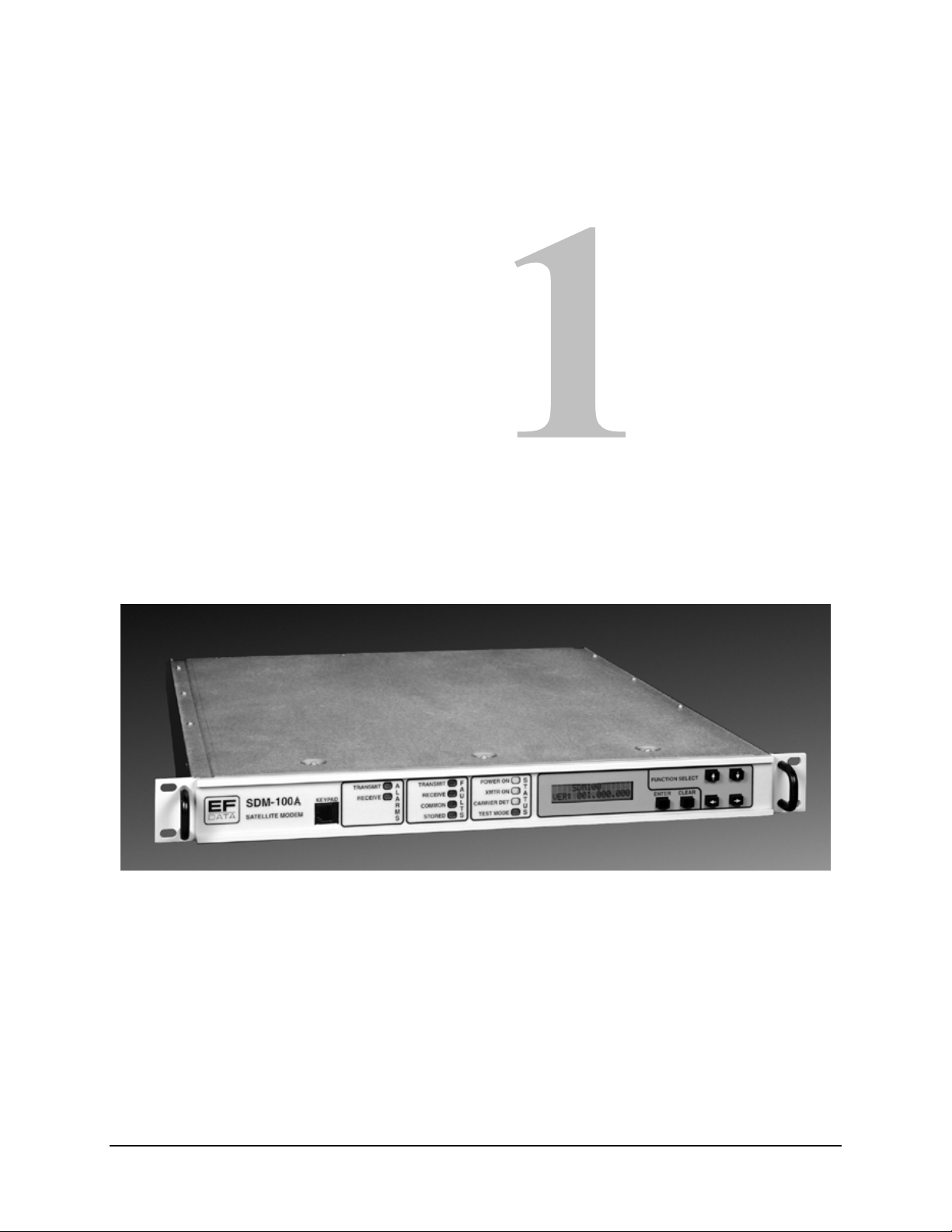
Chapter 1.
INTRODUCTION
This chapter provides the description, options, and specifications for the SDM-100A
satellite modem, referred to in this manual as “the modem” (Figure 1-1).
Figure 1-1. SDM-100A
Rev. 0 1–1
Page 18
Introduction SDM-100A Satellite Modem
A
A
A
ATA
A
A
ATA
ALA
A
A
A
A
A
A
A
A
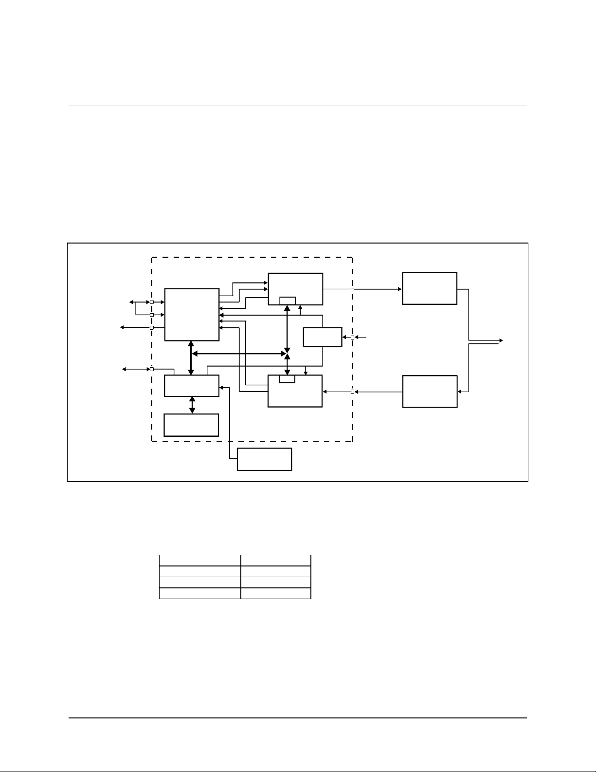
1.1 Purpose and Function
The modem is ideally suited for networks implemented with digitized voice compressors.
These types of circuits require the minimum processing delay provided by the modem’s
Viterbi decoder. A system block diagram is shown in Figure 1-2.
The modem is also employed in transportable applications, where small size and low
power consumption are important.
DPCM
RS-232,
RS-422,
V.35, or
SYNC
CUSTOMER
I/O
D
CLOCK
RMS
FORM C
CONT
CTS
REMOTE
SERI
L
INTERF
CE
SDM-100A
S
TEL LITE
EXT.
MODEM
J8
J8
J7
J6
INTERFACE
MONITOR &
CONTROL
DISPLAY&
KEYP
D
COMMAND
D
CLK
SCT
BUS
DAT
CLK
FRONT
REMOTE
ENCODER/
MODUL
M&C
M&C
DEMOD
DECODER
P
NEL
(OPT.)
TOR
POWER
SUPPLY
IF OUTPUT
CP1
50 to 180 MHz
-5 to -3 0 dBm
90 to 264 VAC,
47 to 63 Hz
IF IN PUT
CP2
50 to90 MHz
100 to 180 MHz
-30to-55dBm
NSMIT
TR
EQUIPMENT
RECEIVE RF
EQUIPMENT
RF
NTENN
Figure 1-2. SDM-100A Block Diagram
The modem provides total flexibility in selection of the following data rates:
19.2 to 128 kbit/s 1/2 rate
28.8 to 192 kbit/s 3/4 rate
33.6 to 224 kbit/s 7/8 rate QPSK
9.6 to 64 kbit/s 1/2 rate BPSK
These parameters, as well as selection of elastic buffer, scrambler, differential encoder,
power levels, and carrier frequencies, can be selected from the front panel, or by remote
control via a serial interface.
Since the modem is software defined, it can be programmed to be end-to-end compatible
with other manufacturer’s modems at similar rates.
1–2 Rev. 0
Page 19

SDM-100A Satellite Modem Introduction
The modem interfaces with IF converter equipment operating in a 50 to 180 MHz band.
The data interface options consist of RS-449/422, V.35, RS-232-C, ASYNC, and
Adaptive Differential Pulse Code Modulation (ADPCM) voice. Changes in connectors
for the various interfaces are accomplished by small, field-changeable connector
modules.
Recent advances in Digital Signal Processing (DSP) have been incorporated into the
modem’s design. Examples of high density components employed in the modem are:
• Embedded microprocessor
• Viterbi Large Scale Integration (LSI) processors
• Direct Digital Synthesis (DDS)
• Field programmable gate arrays for logic processing
Utilization of these state-of-the-art components and surface mount technology provides
maximum modem processing power in a minimum amount of space.
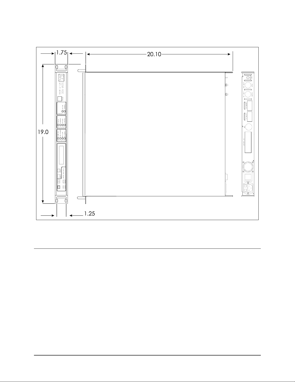
1.2 Description
The modem is a complete, self-contained unit in a standard 1 Unit (1U) 19”
rack-mountable enclosure weighing approximately 10 lbs. A dimensional drawing of the
modem is shown in Figure 1-3.
All monitor and control functions and indicators for operation of the modem are located
on the front panel. The display Printed Circuit Board (PCB) is mounted on the front
panel.
The chassis also contains the power supply. A fan is located on the rear panel.
The modem consists of the following assemblies:
Assembly Drawing #
Chassis with Power Supply AS/5281-X
PCB, Demod/M&C AS/4973
PCB, Interface Daughter (RS-422) AS/2524 (See note below)
PCB, Interface Daughter (V.35) AS/2532 or AS/4326
PCB, Interface Daughter (RS232) AS/2533 (See note below)
PCB, Interface Daughter (ASYNC) AS/4089 (See note below)
PCB, Interface Daughter (ADPCM) AS/3916 (See note below)
PCB, Modulator AS/2522
ASIC, Sequential Decoder IC/EFD 8858 (optional)
PCB, Mod RF AS/3995-X
PCB, Demod RF AS/4401-X
PCB, Reed-Solomon (SDM-100) AS/3708-2
(See note below)
Where X = various options available on the modulator and demodulator boards.
Refer to Table 5-2 for more information on the options available for each board.
Note: Only one interface option is shipped per modem.
Rev. 0 1–3
Page 20
Introduction SDM-100A Satellite Modem
Figure 1-3. Dimensional Drawing
1.3 Options
For more information on the following options, refer to Appendix B.
1.3.1 ASYNC/AUPC Interface
The ASYNC interface board provides the interface for terrestrial data and a single
ASYNC overhead channel, along with an AUPC feature.
1.3.2 ADPCM Voice
The ADPCM voice interface is capable of providing a single, duplex voice channel and
Ear and Mouth (E&M) signaling data transmission.
1–4 Rev. 0
Page 21

SDM-100A Satellite Modem Introduction
1.4 Modem Specifications
Table 1-1 lists the operating specifications of the modem.
Table 1-1. SDM-100A Specifications
Modem Specifications
Operating Frequency Range 50 to 180 MHz, synthesized in 2.5 kHz steps.
Type of Modulation Quadrature Phase Shift Keying (QPSK), or
Bi-Phase Shift Keying (BPSK).
Operating Channel Spacing Less than 0.5 dB degradation operating with 2
adjacent-like channels, each 10 dB higher at 1.3
times the symbol rate, or a minimum of 1.2 times the
specified acquisition range.
Bit Error Rate See Table 1-2.
Phase Noise In accordance with IESS-308.
Digital Interface RS-422/449 on 37-pin D.
(Field Changeable Plug-in modules) MIL-STD-188 on 37-pin D.
(One interface per module.) V.35 on 25-pin DIN.
RS-232-C on 25-pin D.
Asynchronous.
ADPCM.
Digital Data Rate
BPSK, 1/2 Rate 9.6 to 64 kbit/s.
QPSK, 1/2 Rate 19.2 to 128 kbit/s.
QPSK, 3/4 Rate 28.8 to 192 kbit/s.
QPSK, 7/8 Rate 33.6 to 224 kbit/s.
Doppler Buffer Programmable from 64 to 65536 bits, or from 1 to
50 ms total depth.
Buffer Output Clock Transmit, Receive, Internal, or External.
Transmit and external clocks must be to data rate.
Forward Error Correction Convolutional Encoding with Soft Decision.
K=7 Viterbi Decoding, or Sequential.
Data Scrambling Selectable (International Telephone and Telegraph
Consultative Committee) CCITT V.35, or None.
Prime Power 90 to 264 VAC Auto Select, 47 to 63 Hz,
50W Max., Fused at 2A. (48 VDC optional.)
Size 1.75” H x 19.0” W x 20.0” D. Refer to Figure 1-3.
Operating Temperature
Storage Temperature
Humidity 0 to 95% noncondensing.
Diagnostic Features IF Loopback.
RF Loopback.
Baseband Loopback (Bi-directional, electrical).
Fault Monitoring.
Bit Error Rate Monitoring.
Remote Control via Serial Port.
°
0
to 50°C.
°
-20
to +70°C.
Rev. 0 1–5
Page 22

Introduction SDM-100A Satellite Modem
Additional Modulator Specifications
Output Power -5 to -30 dBm, adjustable in 0.1 dB steps.
Output Spurious and Harmonics -55 dBc in 4 kHz BW in-band (50 to 180 MHz).
-55 dBc in 4 kHz BW out-of-band (0 to 500 MHz).
Output Impedance 75Ω standard, or 50Ω optional.
Output Return Loss 20 dB.
Output Frequency Stability ± 10 PPM.
Data Clock Source Internal or external.
External clock,
± 100 PPM and < 5% jitter.
Internal Data Clock Stability ± 10 PPM.
Additional Demodulator Specifications
Input Power (Desired Carrier) -30 to -55 dBm (composite).
+30 dB power within 2 MHz from desired carrier.
+40 dB power outside of 2 MHz from desired carrier.
-5 dBm maximum composite.
Input Impedance 75Ω standard, or 50Ω optional.
Input Return Loss 20 dB.
Carrier Acquisition Range ± 25 kHz minimum.
Clock Acquisition Range ± 100 PPM.
Acquisition Time < 1 second typical at 64 kbit/s.
Directed Sweep:
Sweep Range 0 to 70000 Hz.
Sweep Center -35000 to +35000 Hz.
Remote Control Specifications
Serial Interface RS-232-C or RS-485, Baud Rate 110 to 19,200 bit/s.
Protocol not necessarily compatible with SDM-650B or
SDM-308B.
Signals Controlled/Monitored Transmit Frequency.
Receive Frequency.
Transmit Power.
Transmitter On/Off.
Data Rate Select.
IF Loopback.
RF Loopback.
Baseband Loopback.
Scrambler On/Off.
Descrambler On/Off.
Sweep Range.
Sweep Center.
Filter Mask.
Raw Error Rate.
Corrected Bit Error Rate.
Receive Eb/N0.
TX Clock Internal/External.
RX Clock Normal/Invert.
Receive Signal Level.
Receive Carrier Detect.
Power Supply Voltages.
Fault Status.
Stored Fault Status.
Configuration Retention Will maintain current configuration for up to one year
minimum without power.
Addressing Programmable to 1 of 255 possibilities.
Address 0 reserved for global addressing.
Local control of all remote functions included via push-button entry.
1–6 Rev. 0
Page 23
SDM-100A Satellite Modem Introduction
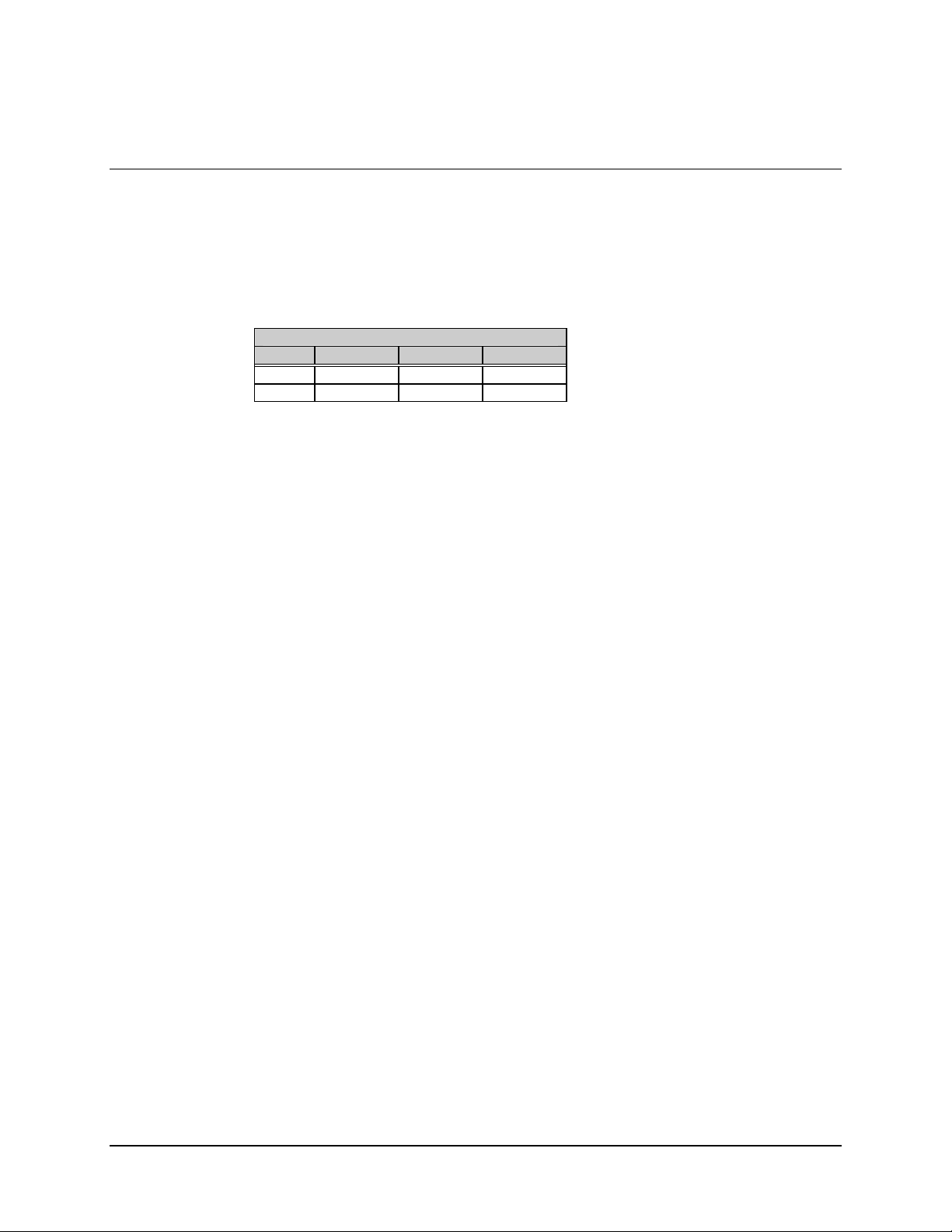
1.5 BER Performance
The bit energy-to-noise ratio (Eb/N0) required to achieve 10-5 to 10-7 bit error rates is listed
in Table 1-2.
Table 1-2. BER Performance Specification
Viterbi K = 7
BER 1/2 Rate 3/4 Rate 7/8 Rate
10-5 5.5 dB 6.8 dB 8.1 dB
10-7 6.7 dB 8.3 dB 9.4 dB
The Bit Error Rate (BER) performance of the modem with a Viterbi decoder is shown in
Figure 1-4.
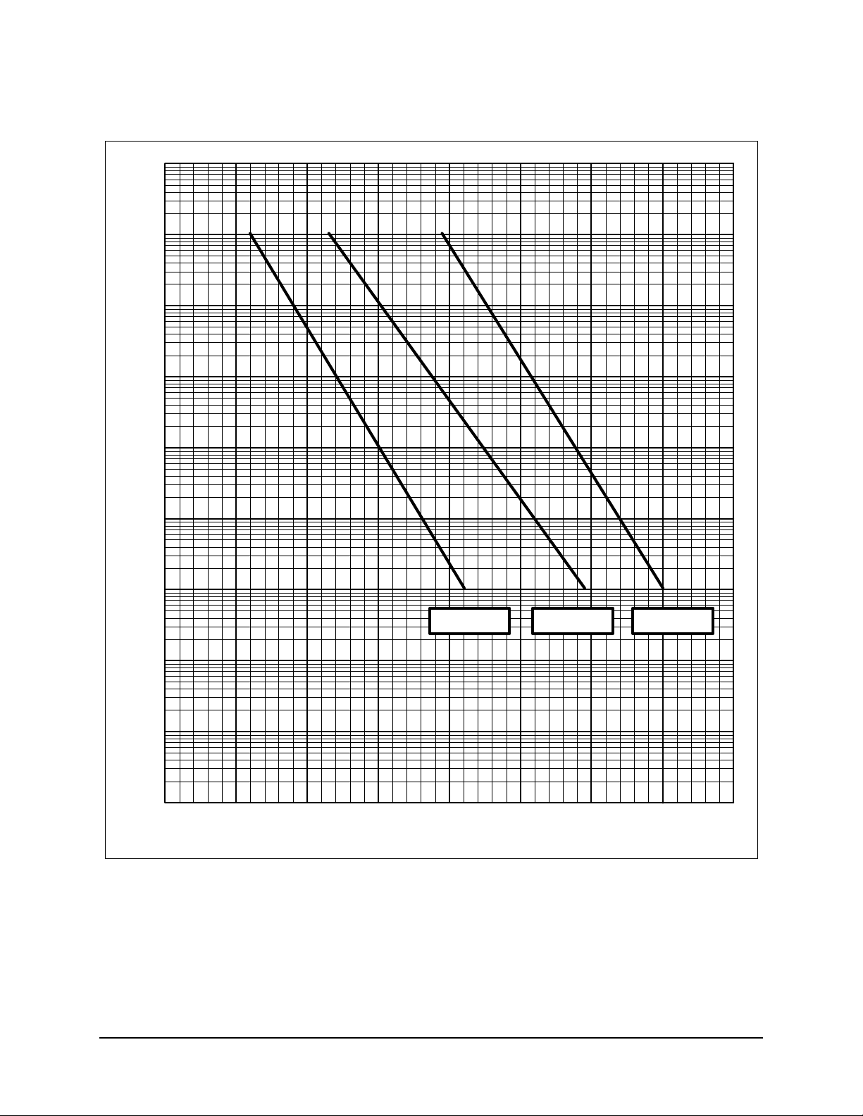
The BER performance of the modem with a sequential decoder is shown in Figure 1-5.
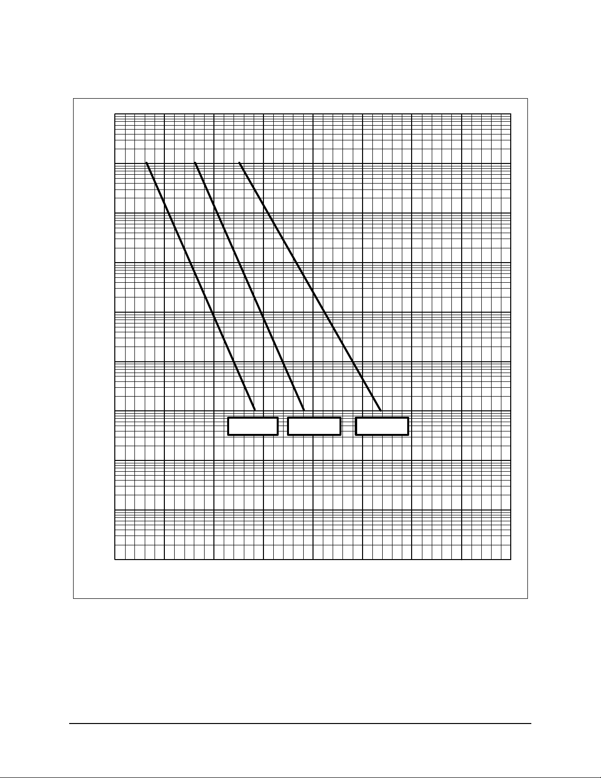
A typical output spectrum of the modem is shown in Figure 1-6.
Notes:
1. The modem alone, without coding, provides operation within 0.5 dB of
theoretical for BPSK, and within 0.8 dB for QPSK, for BERs in the range 10
-6
.
10
2. Performance measurements are made with Transmit and Receive IF connected
back-to-back through an additive white Gaussian noise channel.
3. The BER performance is in accordance with IESS-308 specifications.
-1
to
Rev. 0 1–7
Page 24
Introduction SDM-100A Satellite Modem
-2
10
-3
10
-4
10
-5
10
-6
10
BER
-7
10
-8
10
-9
10
-10
10
3.0 4.0 5.0 6.0
Figure 1-4. Viterbi Bit Error Rate Performance
7/8 RATE3/4 RATE1/2 RATE
7.0 8.0 9.0 10.0 11.0
(dB)
E
b/N0
1–8 Rev. 0
Page 25
SDM-100A Satellite Modem Introduction
-2
10
-3
10
-4
10
-5
10
-6
10
BER
-7
10
-8
10
-9
10
-10
10
3.0 4.0 5.0 6.0
Figure 1-5. Sequential Bit Error Rate Performance
3/4 RATE1/2 RATE 7/8 RATE
7.0 8.0 9.0 10.0 11.0
(dB)
E
b/N0
Rev. 0 1–9
Page 26
Introduction SDM-100A Satellite Modem
/
/
K
RL -10.00 dBm
*ATTEN 0 dB
10.00 dB
DIV
SDM 100
TYPICAL SDM-100A
OUTPUT SPECTRUM
CENTER 70.000 0 MHz
Figure 1-6. Typical Output Spectrum
64 kbit
QPS
s, 1/2RATE
VITERBI
SPAN 500.0 kHz
1–10 Rev. 0
Page 27

This chapter provides unpacking instructions, system requirements, and external
connections for the modem.
2.1 Unpacking
The modem and manual are packaged in pre-formed, reusable cardboard cartons that
contain foam spacing for maximum shipping protection. The circuit cards are contained
in the modem chassis.
To remove the modem:
CAUTION
Chapter 2.
INSTALLATION
Do not use any cutting tool that will extend more than 1” into the container
and cause damage to the modem.
1. Cut the tape at the top of the carton where it is indicated “OPEN THIS END.”
2. Lift out the cardboard/foam spacer covering the modem.
3. Remove the modem, manual, and power cord from carton.
4. Save the packing material for reshipment back to the factory or to another site.
5. Inspect the equipment for damage incurred during shipment.
Rev. 0 2–1
Page 28

Installation SDM-100A Satellite Modem
6. Check the equipment against the packing list shipped with the equipment to
ensure that the shipment is complete.
7. Refer to Section 2.2 for further system installation instructions.
2.2 System Installation
Install the modem as follows:
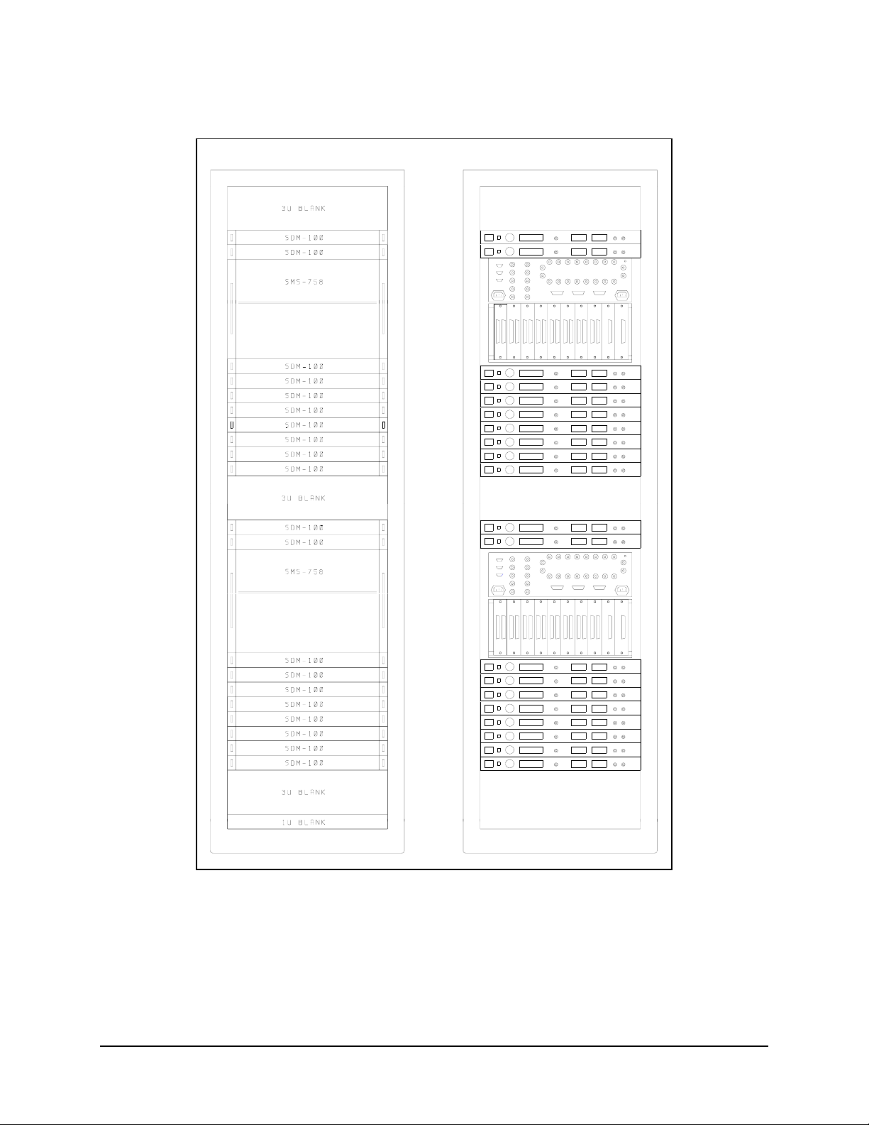
1. Mount the modem chassis in the assigned position in the equipment rack. Refer
to Figure 2-1 for an illustration of a typical rack elevation for an M:N system.
2. Connect the cables to the appropriate locations on the rear panel. Refer to
Section 2.4 for connector pinouts, placement, and functions.
3. Before applying power, read and become familiar with Chapter 3.
Verify all jumper settings are correctly set for remote operation. Refer to
Chapter 4 for jumper settings.
4. Turn on the power switch (located on the rear panel).
5. Check for proper TX output signal level and spectrum.
6. Check for proper RX input signal level and spectrum.
7. If there are any problems with the installation, refer to Chapter 5 for
troubleshooting the system.
2–2 Rev. 0
Page 29

SDM-100A Satellite Modem Installation
2.3 System Requirements
The standard modem with all the cards installed is a full-duplex QPSK satellite modem.
The system can also be configured for TX-only or RX-only.
• For a TX-only system, enter the UTILITY SYSTEM menu under FUNCTION
SELECT UTILITY on the front panel. Select OPERATION MODE.
Enter the menu and select Transmit Only. This will mask all receive faults and
receive stored faults in the Faults menu.
• For an RX-only system, enter the UTILITY SYSTEM menu under FUNCTION
SELECT UTILITY on the front panel. Select OPERATION MODE.
Enter the menu and select Receive Only. This will mask the transmit faults and
transmit stored faults in the Faults menu.
Rev. 0 2–3
Page 30
Installation SDM-100A Satellite Modem
$
$
$
$
$
$
$
$
$
$
$
$
$
$
$
$
$
$
$
$
Figure 2-1. Typical Rack Elevation
2–4 Rev. 0
Page 31

SDM-100A Satellite Modem Installation
2.4 External Connections
Connections between the modem and other equipment are made through five connectors.
These connectors are listed in Table 2-1, and their locations are shown in Figure 2-2.
The use of each connector is described in the following paragraphs.
Table 2-1. Rear Panel Connectors
Name Ref.
Desig.
DATA I/O J8 Various: Data Input/Output:
37-pin D RS-422/449
34-pin block or
25-pin D RS-232
50-pin D ASYNC
50-pin D ADPCM Voice
REMOTE J6 9-pin D Remote Interface
FAULTS J7 9-pin D FORM-C Fault Relay
TX/IF OUTPUT CP1 BNC TX IF Output
RX/IF INPUT CP2 BNC RX IF Input
AC POWER None Standard Alternating Current (AC)
DC POWER None Terminal block Direct Current (DC)
CHASSIS GND GND #10-32 stud Chassis Ground
AGC AGC Test point Automatic Gain Control (AGC)
Connector
Type
25-pin D
Function
V.35
Contacts
Power Input
Power Input
Test Point
Figure 2-2. Rear Panel View
Rev. 0 2–5
Page 32

Installation SDM-100A Satellite Modem
2.4.1 DATA I/O Interface (J8)
The DATA I/O interface connector is used to interface data input and output signals to
and from the modem. The DATA I/O connects to the customer terrestrial equipment
directly or through a protection switch.
The DATA I/O interface can be MIL-STD-188, RS-422/449, V.35, or RS-232-C.
The interface module of the modem is mounted directly on the modulator board. The
modem operates with a single interface configuration. Field changes are easily done by
changing the interface module (refer to Chapter 4).
2.4.2 Remote (J6)
The Remote connector on the modem is used to interface the Monitor and Control
(M&C) functions to a remote location. This interface can be either RS-232-C or RS-485.
For a more information on the remote interface, refer to Chapter 4.
The remote interface is provided on a 9-pin female D connector. Screw locks are
provided for mechanical security of the mating connector.
The remote connector is a Data Circuit Terminating Equipment (DCE) interface.
There are jumpers on the demodulator board that must be set to select either RS-485 or
RS-232-C remote interface.
Refer to Chapter 4 for configuration information.
RS-485 RS-232-C
4-Wire Mode 2-Wire Mode 4- and 2-Wire Mode
Pin Name Pin Name
1 GND GND 1
2 2 RD (RX)
3 3 TD (TX)
4 + TX + RX/TX 4
5 - TX - RX/TX 5 GND
6 6 Data Signal Rate (DSR)
7 7 Request to Send (RTS)
8 +RX + RX/TX 8 Clear to Send (CTS)
9 - RX - RX/TX 9
2–6 Rev. 0
Page 33

SDM-100A Satellite Modem Installation
2.4.3 Faults (J7)
The Fault connector on the modem is used to interface FORM-C contact closures for the
purpose of fault reporting. There are three FORM-C summary fault contacts:
• Modulator
• Demodulator
• Common equipment
For further discussion on the monitored faults, refer to Chapter 3.
To obtain a system summary fault, connect all FORM-C contacts in parallel.
The fault interface is provided on a 9-pin female D connector. Screw locks are provided
for mechanical security on the mating connector.
Pin # Name Function
1 NO Common Equipment is OK
2 COM
3 NC Common Equipment is FAULTED
4 NO Modulator is OK
5 COM
6 NC Modulator is FAULTED
7 NO Demodulator is OK
8 COM
9 NC Demodulator is FAULTED
Note: A connection between the Common (COM) and Normally Open (NO) contacts
indicates no fault.
2.4.4 TX IF Output (CP1)
This is the transmit IF connector. The output impedance is 75Ω (50Ω optional), and the
output power level is -5 to -30 dBm, in 0.1 dB steps.
For normal operation, the output will be a QPSK modulated result of the DATA I/O
connector, between 50 and 180 MHz.
Rev. 0 2–7
Page 34

Installation SDM-100A Satellite Modem
2.4.5 RX IF Input (CP2)
This is the receive IF connector. The input impedance is 75Ω (50Ω optional).
For normal operation, the desired carrier signal level should be between -30 and
-55 dBm. Signals between 50 and 180 MHz are selected and demodulated to produce
clock and data at the DATA I/O connector.
2.4.6 AC Power
The AC power is supplied to the modem by a standard detachable, non-locking, 3-prong
power cord.
Normal input voltage is 90 to 264 VAC, 47 to 63 Hz. The modem will automatically
switch between ranges.
Maximum power consumption is less than 40W.
2.4.7 DC Power
DC power is available as an option. The DC power is supplied to the modem by a
3-position terminal block.
Normal input voltage is 48 VDC,
Maximum power consumption is less than 40W.
2.4.8 GND
A #10-32 stud is available on the rear for the purpose of connecting a common chassis
ground between all of the equipment.
Note: The safety ground is provided through the AC power connector.
2.4.9 AGC Test Point
The Automatic Gain Control (AGC) test point is a BNC connector on the rear panel of
the modem chassis. This feature allows the user to monitor the AGC.
± 10%.
2–8 Rev. 0
Page 35

This chapter describes the front panel operation and clocking configurations of the
modem.
For remote control operation information, refer to Appendix A.
3.1 Front Panel
The front panel of the modem (Figure 3-1) provides the local user interface, which is
necessary to configure and monitor status of the modem.
Chapter 3.
OPERATION
Figure 3-1. Front Panel View
The front panel features a 32-character, 2-line, Liquid Crystal Display (LCD), and a
6-button keypad, which provides for sophisticated functions, yet is easy to use.
Ten Light-Emitting Diodes (LEDs) on the front panel provide overall status at a glance.
Rev. 0 3–1
Page 36

Operation SDM-100A Satellite Modem
3.1.1 Front Panel Keypad Option
This feature is a future option which will allow the user to plug in a hand-held keypad,
and will allow access to all programming capabilities.
3.1.2 LED Indicators
General modem status and summary faults are indicated by 10 LEDs on the front panel.
The indicators are defined as follows:
Faults
Name LED Color Meaning
Transmit Red Indicates that a fault condition exists in the transmit chain.
Receive Red Indicates that a fault condition exists in the receive chain.
Common fault Red Indicates that a common equipment fault condition exists.
Stored Yellow Indicates that a fault has been logged and stored.
The fault may or may not be active.
Status
Power On Green Indicates that power is applied to the modem.
Transmitter On Green Indicates that the transmitter is currently on. This indicator
reflects the actual condition of the transmitter, as opposed to
the programmed condition.
Carrier Detect Green Indicates that the decoder is locked.
Test Mode Yellow Flashes when the modem is in a test configuration.
Alarms
Transmit Yellow Indicates that a transmit function is in an alarm condition.
Receive Yellow Indicates that a receive function is in an alarm condition.
3–2 Rev. 0
Page 37

SDM-100A Satellite Modem Operation
3.1.3 Front Panel Controls
The modem is locally operated by using the front panel keypad (Figure 3-1), which
consists of the following keys:
[ENTER] This key is used to select a displayed function, or to execute a change to the
modem’s configuration.
[CLEAR] This key is used to back out of a selection, or to cancel a configuration change
which has not been executed using [ENTER].
Pressing [CLEAR] generally returns the display to the previous selection.
[←] and [→] These keys are used to move to the next selection, or to move the cursor for
certain functions.
[↑] and [↓] These keys are used primarily to change configuration data (numbers), but are
also used at times to move from one section to another.
The modem responds by beeping whenever a key is pressed.
• A single beep indicates that the key pressed was a valid entry and the appropriate
action was taken.
• A double beep when a key is pressed indicates an invalid entry.
Rev. 0 3–3
Page 38

Operation SDM-100A Satellite Modem
3.2 Menu System
In order to access and execute all functions, refer to the menus in Figures 3-2 through
3-25. Use the main menu in Figure 3-2 as a quick reference for accessing all modem
functions. For further configuration details, refer to Section 3.3.
The base level of this structure is the sign-on message, which is displayed on the front
panel upon modem power up. Line 1 of the sign-on message shows the modem type
(SDM-100 or Type 1), and line 2 shows the version number of the firmware implemented
in the modem.
The main level of the menu system is the “FUNCTION SELECT” menu, which may be
accessed from the base level by pressing any of the arrow keys.
From the “FUNCTION SELECT” menu, any one of six functional categories may be
selected:
• Configuration functions
• Monitor functions
• Fault functions
• Stored fault functions
• Remote AUPC functions
• Utility functions
←] or [→] to move from one selection to another. When the desired function is
Press [
displayed on line 2, select that level by pressing [ENTER].
Once the desired functional level has been entered, move to the desired function by
pressing [
←] or [→].
3–4 Rev. 0
Page 39

SDM-100A Satellite Modem Operation
3.2.1 Standard SDM-100 Menus
SDM-100 "TYPE"
VER: 14.7.4
FUNCTION SELECT
CONFIGURATION
CONFIGURATION
MODULATOR
(Figure 3-3)
CONFIGURATION
DEMODULATOR
(Figure 3-4)
CONFIGURATION
INTERF ACE
(Figure 3-5)
CONFIGURATION
LOCAL AUPC
(Figure 3-6)
FUNCTION SELECT
MONITOR
(Figure 3-7)
FUNCTION SELECT
FAULTS/ALARMS
(Figure 3-8)
FUNCTION SELECT
STORED
FLT/ALMS
(Figure 3-9)
REMOTE AUPC
(Figure 3-10)
FUNCTION SELECT
UTILITY
UTILITY
MODULATOR
(Figure 3-11)
UTILITY
DEMODULATOR
(Figure 3-12)
UTILITY
INTERF ACE
(Figure 3-13)
UTILITY
SYSTEM
(Figure 3-14
UTILITY
MODEM TYPE
(Figure 3-15)
Key:
ACCESS TO
SUBMENU
CONDITIONAL OR
OPTION-DEPENDENT
Parameter Information
UTILITY
FACTORY SETUP
(Figure 3-16)
Figure 3-2. Main Menu (SDM-100 Operation)
Rev. 0 3–5
Page 40

Operation SDM-100A Satellite Modem
This page is intentionally left blank.
3–6 Rev. 0
Page 41

SDM-100A Satellite Modem Operation
3.2.1.1 Configuration
Modem configuration may be viewed or changed by entering the “CONFIGURATION”
level from the “FUNCTION SELECT” menu on the front panel.
After entering the “CONFIGURATION” menu, press [
“MODULATOR,” “DEMODULATOR,” “INTERFACE,” or “LOCAL AUPC” (if that
option is installed).
Enter the selected configuration menu by pressing [ENTER].
←] or [→] to view the selected configuration parameters.
Press [
To change a configuration parameter, press [ENTER] to begin the change process. Press
↑] or [↓] to make the changes.
[
After the changes are made and the display represents the correct parameters, execute the
changes by pressing [ENTER]. After [ENTER] is pressed, the necessary programming is
initiated by the modem. To undo a parameter change prior to executing it, simply press
[CLEAR].
The modem configuration functions are outlined in the following paragraphs.
←] or [→] to select
Rev. 0 3–7
Page 42

Operation SDM-100A Satellite Modem
SDM-100 "TYPE"
VER: 14.7.4
TX-X CODE_RATE/
TYPE
x = A, B, C, D, or V
TX-A QPSK 1/2 64.000 kbit/s
TX-B QPSK 1/2 96.000 kbit/s
TX-C QPSK 1/2 128.000 kbit/s
TX-D QPSK 1/2 38.400 kbit/s
TX-V QPSK 1/2 19.200 kbit/s
SCRAMBLER DIFF. ENCODER CARRIER MODE
FUNCTION SELECT
CONFIGURATION
ON
OFF
CONFIGURATION
MODULATOR
TX-IF FREQUENCY TX-IF OUTPUT
50 to 180 MHz
in 2.5 kHz steps.
ON
OFF
OFF
ON
NORMAL (OFF)
CENTER
DUAL
OFFSET
TX POWER LEVEL
(Fixed or Adj.)
-5 to -30 dBm
in 0.1dBm steps.
Key:
ACCESS TO
SUBMENU
CONDITIONAL OR
OPTION-DEPENDENT
Parameter Information
Figure 3-3. Configuration Modulator (SDM-100 Operation)
3–8 Rev. 0
Page 43

SDM-100A Satellite Modem Operation
3.2.1.1.1 Configuration Modulator
TX-X
Code_Rate/Type
Transmitter Rate selection.
One of four predefined transmitter code/data rate combinations may be
selected: A, B, C, or D, or a variable rate selection (V). These selections
must first be set up in the Utility menu.
On entry, the current transmitter rate is displayed with the flashing cursor
on the first character of the code rate on line 1. The data rate is displayed
on line 2. Press [
D). To select the variable data rate, select “TX-V” and press [ENTER]
↑] or [↓] to select one of four predefined rates (A, B, C, or
twice.
To change the rate in the variable rate selection, press [ENTER]
when
“TX-V” is displayed. A flashing cursor will be displayed on the first character
of the coding type on line 1. Press [
Press [
↑] or [↓] to increment or decrement the digit at the flashing cursor.
Press [ENTER]
to execute the change.
←] or [→] to move the flashing cursor.
To operate BPSK, select “TX-V” and select BPSK 1/2 for the code rate,
then enter the data rate from 9.6 to 64 kbit/s. Press [ENTER]
to execute the
change.
Note: When the TX Rate has been changed, the transmitter is
automatically turned off to prevent swamping of other channels. To turn the
transmitter on, use the “IF Output” function.
TX-IF Frequency Programs the modulator transmit frequency between 50 and 180 MHz, in
2.5 kHz steps.
On entry, the current transmitter frequency is displayed with the flashing
cursor on the first character. Press [
Press [
↑] or [↓] to increment or decrement the digit at the flashing cursor.
Press [ENTER]
to execute the change.
←] or [→] to move the flashing cursor.
Note: When the transmitter frequency is changed, the transmitter is
automatically turned off to prevent the possible swamping of other
channels. To turn the transmitter on, use the “IF Output” function.
TX-IF Output Programs the modulator output to ON or OFF.
On entry, the current status of the output is displayed. Press [
select ON or OFF. Press [ENTER]
to execute the change.
↑] or [↓] to
Rev. 0 3–9
Page 44

Operation SDM-100A Satellite Modem
TX Power Level Programs the modulator output power level from -5 to -30 dBm, in 0.1 dBm
steps. The high power option operates from + 5 to -20 dBm.
On entry, the current transmitter power level is displayed with the flashing
cursor on the first character. Press [
output power level in 0.1 dB steps. Press [ENTER]
Note: The actual front panel display may be changed in the Power Offset
Utility function (Section 3.2.1.6.1). Using this function does not change the
actual output power level. When the offset feature is being used, (ADJ) will
be displayed on line 2.
Scrambler Programs the scrambler ON or OFF.
On entry, the current status of the V.35 Scrambler is displayed. Press [
[
↓] to select ON or OFF. Press [ENTER] to execute the change.
Diff. Encoder Programs the differential encoder ON or OFF.
On entry, the current status of the Differential Encoder is displayed. Press
[
↑] or [↓] to select ON or OFF. Press [ENTER] to execute the change.
Carrier Mode Programs the modem for continuous wave mode. Four modes of
operation are available: Normal (OFF), Center, Dual, and Offset modes.
The Carrier mode is normally in the OFF position.
To change to Center, Dual, or Offset mode, enter the Carrier Mode Menu
and select the desired test mode.
Center Mode: A test mode that generates a carrier at the current
modulator frequency. This can be used to measure the output
frequency.
Dual Mode: A test mode that generates a dual side-band
suppressed carrier signal. Side-bands are one-half the symbol rate
from the carrier. This is used to check the channel balance and
carrier null.
Offset Mode: A test mode that generates a single upper side-band
suppressed carrier signal. The upper side-band is one-quarter the
symbol rate from the carrier. This is used to check the quadrature.
On entry, the “CENTER” mode is displayed. To activate this test mode,
press [ENTER].
Press [↑] or [↓] to select the “DUAL” or “OFFSET” mode.
To return to the “CONFIGURATION” menu, press [CLEAR].
Note: When [CLEAR] is pressed, the modem is configured to the state it
was in before “CW Mode” was invoked. The transmitter is automatically
turned off to prevent the possible swamping of other channels. To turn
the transmitter on, use the “IF Output” function.
↑] or [↓] to increase or decrease the
to execute the change.
↑] or
3–10 Rev. 0
Page 45

SDM-100A Satellite Modem Operation
This page is intentionally left blank.
Rev. 0 3–11
Page 46

Operation SDM-100A Satellite Modem
SDM-100 "TYPE"
VER: 14.7.4
RX-X CODE_RATE/
TYPE
x = A, B, C, D, or V
TX-A QPSK 1/2 64.000 kbit/s
TX-B QPSK 1/2 96.000 kbit/s
TX-C QPSK 1/2 128.000 kbit/s
TX-D QPSK 1/2 38.400 kbit/s
TX-V QPSK 1/2 19.200 kbit/s
RF LOOP BACK IF LOOP BACK BER THRESHOLD
OFF
ON
SWEEP RANGE
FUNCTION SELECT
CONFIGURATION
RX-IF FREQUENCY DESCRAMBLER DIFF. DECODER
50 to 180 MHz
In 2.5 kHz steps.
OFF
ON
CONFIGURATION
DEMODULATOR
ON
OFF
1.0 E-3 to 1.0 E-8
NONE
ON
OFF
SWEEP CENTER
-35000 to +35000 Hz
0 to 70000 Hz
Key:
ACCESS TO
SUBMENU
CONDITIONAL OR
OPTION-DEPENDENT
Parameter Information
Figure 3-4. Configuration Demodulator (SDM-100 Operation)
3–12 Rev. 0
Page 47

SDM-100A Satellite Modem Operation
3.2.1.1.2 Configuration Demodulator
RX-X
Code_Rate/Type
Receiver rate selection. One of four predefined receiver
decoder/data rate combinations (A, B, C, or D) or a variable rate
selection (V) may be selected. These selections must first be set up
in the Utility menu.
On entry, the current receiver rate is displayed with the flashing
cursor on the first character of the code rate on line 1. The data rate
is displayed on line 2. Press [
↑] or [↓] to select one of four predefined
rates (A, B, C, or D).
To select the variable data rate, select “RX-V” and press [ENTER]
twice to select the currently defined data rate.
To change the rate in the variable rate selection, press [ENTER]
when “RX-V” is displayed. A flashing cursor will be displayed on the
first character of the coding type on line 1. Press [
the flashing cursor. Press [
↑] or [↓] to increment or decrement the
digit at the flashing cursor. Press [ENTER]
←] or [→] to move
to execute the change.
RX-IF Frequency Programs the receive frequency between 50 and 180 MHz, in
2.5 kHz steps.
On entry, the current receive frequency is displayed with the flashing
cursor on the first character. Press [
cursor. Press [
↑] or [↓] to increment or decrement the digit at the
flashing cursor. Press [ENTER]
←] or [→] to move the flashing
to execute the change.
Descrambler Programs the V.35 descrambler ON or OFF.
On entry, the current status of the descrambler is displayed. Press
[
↑] or [↓] to select ON or OFF. Press [ENTER] to execute the change.
Diff. Decoder Programs the differential decoder ON or OFF.
On entry, the current status of the differential decoder is displayed.
Press [
↑] or [↓] to select ON or OFF. Press [ENTER] to execute the
change.
RF Loop Back Programs the modem for RF loopback operation (test mode).
When RF loopback is turned on, the demodulator is programmed to
the same frequency as the modulator. When RF loopback is turned
off, the demodulator is tuned to its previous frequency. Refer to
Figure 3-26 for a block diagram of RF loopback operation.
Note: RF loopback nullifies IF loopback.
On entry, the current status of RF loopback is displayed. Press [
[
↓] to select ON or OFF. Press [ENTER] to execute the change.
↑] or
Rev. 0 3–13
Page 48

Operation SDM-100A Satellite Modem
IF Loop Back Programs the modem for IF loopback operation (test mode).
When IF loopback is turned on, the demodulator input is connected to
the modulator output through an internal attenuator, and the
demodulator is programmed to the same frequency as the modulator.
An attenuator within the modem connects the IF out to the IF in. When
IF loopback is turned off, the demodulator is tuned to its previous
frequency, and is reconnected to the IF input. Refer to Figure 3-27 for
a block diagram of IF loopback operation.
Note: IF loopback nullifies RF loopback.
On entry, the current status of IF loopback is displayed. Press [
to select ON or OFF. Press [ENTER]
to execute the change.
BER Threshold This function is used to set the BER threshold.
If the set BER threshold is exceeded, a receive fault will be indicated
by the modem status indicators. BER threshold may be set from 1E
-8
to 1E
, or may be disabled by specifying NONE.
On entry, the current setting of the BER threshold is displayed. Press
[
↑] or [↓] to select the desired setting. Press [ENTER] to execute the
change.
Sweep Center Programs the sweep center frequency for the directed sweep function.
The sweep center frequency may be set in the range from -35000 to
+35000 Hz.
On entry, the current programmed setting is displayed with a flashing
cursor on the first character. Press [
cursor. Press [
↑] or [↓] to increment and decrement the digit at the
←] or [→] to move the flashing
flashing cursor. Select the sweep center frequency from -35000 to
+35000 Hz. Press [ENTER]
to execute the change.
When in directed sweep, the value from the sweep monitor screen
(when the modem was last locked) should be entered for the sweep
center frequency.
Sweep Range Programs the overall travel of the sweep width range during acquisition
in the directed sweep mode.
The sweep width may be set from 0 to 70000 Hz. (When set at 70000
Hz, the modem is in the normal acquisition mode.)
On entry, the current programmed setting is displayed with a flashing
cursor on the first character. Press [
cursor. Press [
↑] or [↓] to increment and decrement the digit at the
←] or [→] to move the flashing
flashing cursor. Select a sweep range from 0 to 70000 Hz. Press
[ENTER]
to execute the change.
Note: The smaller the range is, the faster the modem will lock,
provided the receive carrier center frequency is within the RX IF
frequency sweep range.
↑] or [↓]
-3
3–14 Rev. 0
Page 49

SDM-100A Satellite Modem Operation
This page is intentionally left blank.
Rev. 0 3–15
Page 50

Operation SDM-100A Satellite Modem
SDM-100 "TYPE"
VER: 14.7.4
TX CLOCK SOURCE TX CLOCK PHASE BUFFER CLOCK
TX TERRESTRIAL
RX (SATELLITE)
SCT (INTERNAL)
B-BAND LOOP BACK
OFF
ON
ASYNC INTERFACE
FUNCTION SELECT
CONFIGURATION
AUTO
NORMAL
INVERT
BUFFER SIZE BUFFER CENTER
64 to 65536 Bits
in 16-bit steps or
Bypass = 0 bits.
0 to 50 ms
ASYNC TX
BAUD
CONFIGURATION
INTERFACE
RX (SATELLITE)
SCT (INTERNAL)
EXT. REFERENCE
TX TERRESTRIAL
YES/NO
ASYNC RX
BAUD
RX CLOCK PHASE
NORMAL
INVERT
LOOP TIMING
ON
OFF
(ASYNC only)
ASYNC TX
LENGTH
ON
OFF
(ASYNC only)
ASYNC RX
LENGTH
5 to 8 bits
(ASYNC only)
150 to 2400 bits
(ASYNC only)
ASYNC TX
PARITY
ODD
EVEN
NONE
(ASYNC only)
150 to 2400 bits
(ASYNC only)
ASYNC RX
PARITY
ODD
EVEN
NONE
(ASYNC only)
Key:
ACCESS TO
SUBMENU
CONDITIONAL OR
OPTION-DEPENDENT
Figure 3-5. Configuration Interface (SDM-100 Operation)
5 to 8 bits
(ASYNC only)
B
Parameter Information
3–16 Rev. 0
Page 51

SDM-100A Satellite Modem Operation
B ASYNC TX STOP
1 or 2 bits
(ASYNC only)
EM CIRCUIT
1, 2, 3, or 4
(ADPCM only)
TX CHANNEL
LEVEL= X
-20 to +10
in 1 dBm steps
(ADPCM only)
ADPCM INTF
ON/OFF
(ADPCM only)
ENCODING TYPE
A-LAW
µ-LAW
(ADPCM only)
RX CHANNEL
LEVEL= X
-20 to +10
in 1 dBm steps
(ADPCM only)
CIRCUIT TYPE
TRUNK
SUBSCRIBER
(ADPCM only)
ON HOOK/
OFF HOOK
ON HOOK
OFF FOOK
(ADPCM only)
Key:
ACCESS TO
SUBMENU
CONDITIONAL OR
OPTION-DEPENDENT
Parameter Information
Figure 3-5. Configuration Interface Continued (SDM-100 Operation)
Rev. 0 3–17
Page 52

Operation SDM-100A Satellite Modem
3.2.1.1.3 Configuration Interface
TX Clock Source Programs the clock source for the modem transmitter clock.
“TX Terrestrial” sets the TX clock to recover timing from the
incoming clock/data.
“RX (Satellite)” sets the TX clock to operate from the satellite clock.
“SCT (Internal)” sets the TX clock to operate from the modem
internal clock. This is also the fallback clock.
On entry, the current transmit clock setting is displayed. Press [
[
↓] to select “SCT,” “TX Terrestrial,” or “RX (Satellite)” clock. Press
[ENTER]
to execute the change.
TX Clock Phase Programs Transmit Clock phase to “Auto,” “Normal,” or “Invert.”
On entry, the current setting for the TX clock phase is displayed.
Press [
↑] or [↓] to select “Auto,” “Normal,” or “Invert.” When “Auto” is
selected, the modem will automatically select normal or invert to
properly phase the transmit clock with the transmit data. Press
[ENTER]
to execute the change.
Buffer Clock Programs interface buffer output clock.
“RX (SATELLITE)” sets the output buffer clock to the satellite clock.
“SCT (INTERNAL)” sets the buffer clock to operate from the modem
internal clock. This is also the fallback clock.
“EXT. REFERENCE” sets this clock source to the Master Clock (or
Terminal Timing) external reference, which is received on the DATA
I/O connector on the rear of the modem.
“TX TERRESTRIAL” sets the buffer output clock to recover timing
from the incoming TX data clock.
On entry, the current setting of the interface buffer clock is displayed.
Press [
↑] or [↓] to select “RX (SATELLITE),” “SCT (INTERNAL),”
“EXT. REFERENCE,” or “TX TERRESTRIAL” for the buffer clock.
Press [ENTER]
to execute the change.
RX Clock Phase Programs the RX clock phase to “Normal” or “Inverted.”
On entry, the current status of the RX Clock is displayed. Press [
[
↓] to select “Normal” or “Invert.” Press [ENTER] to execute the
change.
↑] or
↑] or
3–18 Rev. 0
Page 53

SDM-100A Satellite Modem Operation
B-Band Loop Back Programs the modem for baseband loopback operation (test mode).
When baseband loopback is turned on, the data and timing signals
are hard-wired (via relays) from the demodulator to the modulator on
the modem side of the interface. The Data Terminal Equipment (DTE)
baseband signals are also looped back from the transmitter data and
clock to the receiver data and clock on the customer side of the
interface. This is a bi-directional loopback of the baseband data.
Refer to Figure 3-28 for a block diagram of baseband loopback
operation.
On entry, the current status is displayed. Press [
or OFF. Press [ENTER]
to execute the change.
↑] or [↓] to select ON
Buffer Size This configuration function is used to set the size of the buffer.
On entry, the current buffer length is displayed. Press [
↑] or [↓] to
select the desired buffer size. The buffer size will be displayed in
milliseconds or bits. (To change the buffer units to milliseconds or
bits, enter the “Function Select Utility” menu, select the “Interface
Utility” menu, and select Buffer Program.) The range which may be
selected is 64 to 65,536 bits, in increments of 16, or Bypass, which
equals 0 bits. If milliseconds are selected, 0 to 50 ms, in increments
of 1 ms may be chosen. Press [ENTER]
to execute the change.
Note: To have the modem calculate the buffer depth, set the buffer
units to milliseconds. When a specific buffer depth is desired, set the
buffer units to bits. To select bits or milliseconds, enter the “Utility
Interface” menu, and make the change.
Buffer Center Configuration function used to center the buffer.
On entry, the current status is displayed. Press [
or NO. Press [ENTER]
to execute the change.
↑] or [↓] to select YES
Loop Timing This puts the modem in a loop timing configuration. The buffer clock and
the ST pin on the interface are forced to the RX clock. Available only
with the ASYNC option installed.
On entry, the current status is displayed. Press [
or NO. Press [ENTER]
to execute the change.
↑] or [↓] to select YES
ASYNC Interface This turns the ASYNC overhead ON or OFF.
TX Baud This programs the TX UART to the desired baud rate for the ASYNC
channel. Available only with the ASYNC option installed.
RX Baud This programs the RX UART to the desired baud rate for the ASYNC
channel. Available only with the ASYNC option installed.
TX Length This programs the TX UART to the desired number of data bits.
Available only with the ASYNC option installed.
RX Length This programs the RX UART to the desired number of data bits.
Available only with the ASYNC option installed.
TX Parity This programs the TX UART for the desired parity. Available only with
the ASYNC option installed.
RX Parity This programs the RX UART for the desired parity. Available only with
the ASYNC option installed.
TX Stop This programs the TX UART to output the desired number of stop bits.
Available only with the ASYNC option installed.
Rev. 0 3–19
Page 54

Operation SDM-100A Satellite Modem
ADPCM Intf ADPCM interface ON/OFF selection. If ADPCM is set ON, the ADPCM
operation is selected. If ADPCM is set OFF, then the standard RS-422
interface option is selected. Available only with the ADPCM option
installed.
Circuit Type This refers to the emulation mode of the modem ADPCM interface.
When the subscriber is selected, the modem interface is configured as
a subscriber circuit. When the trunk is selected, the modem interface is
configured as a trunk. Available only with the ADPCM option installed.
E&M Circuit This allows the user to chose which E&M signaling type is selected.
Types 1 to 4 are supported. Available only with the ADPCM option
installed.
Encoding Type
On Hook/Off Hook Selects between ON HOOK and OFF HOOK operation. Available only
TX Channel Level This allows the user to set the input level for the transmit audio from -20
RX Channel Level This allows the user to set the input level for the receive audio from -20
This configures the audio channel to support either A-law or µ-law
encoding. Available only with the ADPCM option installed.
with the ADPCM option installed.
to +10 dBm, in 1 dBm steps. Available only with the ADPCM option
installed.
to +10 dBm, in 1 dBm steps. Available only with the ADPCM option
installed.
3–20 Rev. 0
Page 55

SDM-100A Satellite Modem Operation
This page is intentionally left blank.
Rev. 0 3–21
Page 56

Operation SDM-100A Satellite Modem
SDM-100 "TYPE"
VER: 14.7.4
AUPC ENABLE NOMINAL POWER MINIMUM POWER MAXIMUM POWER
ON/OFF -30 to -5 dBm -30 to -5 dBm -30 to -5 dBm
TARGET NOISE TRACKING RATE LOCAL CL ACTION
3.2 to 9.7 dB
in 0.1 dB increments
FUNCTION SELECT
CONFIGURATION
0.5 to 6.0 dBm per minute
CONFIGURATION
LOCAL AUPC
(AUPC only)
If carrier lock is detected
MAXIMUM
NOMINAL
HOLD
If carrier lock is detected
Key:
ACCESS TO
SUBMENU
CONDITIONAL OR
OPTION-DEPENDENT
REMOTE CL
ACTION
MAXIMUM
NOMINAL
HOLD
Parameter Information
Figure 3-6. Configuration Local AUPC (SDM-100 Operation)
3–22 Rev. 0
Page 57

SDM-100A Satellite Modem Operation
3.2.1.1.4 Configuration Local AUPC
AUPC Enable This option turns the local modem’s AUPC ON or OFF.
Nominal Power This option programs the nominal power set point for AUPC from -30
to -5 dBm.
Minimum Power This option programs the minimum power set point for AUPC from -
30 to -5 dBm.
Maximum Power This option programs the maximum power set point for AUPC from -
30 to -5 dBm.
Target Noise This option programs the target Eb/N0 setpoint. The Eb/N0 setpoint
can range from 3.2 to 9.7 dB, in 0.1 dB increments.
Tracking Rate This option programs the maximum tracking rate. The maximum
tracking rate can range from 0.5 to 6.0 dBm per minute.
Local CL Action This option programs the action taken by the local modem if Carrier
Loss is detected. The local CL can be programmed to Maximum,
Nominal, or Hold.
Remote CL Action This option programs the action taken by the remote modem if
Carrier Loss is detected. The remote CL can be programmed to
Maximum, Nominal, or Hold.
Rev. 0 3–23
Page 58

Operation SDM-100A Satellite Modem
A
SDM-100 "TYPE"
VER: 14.7.4
RAW BER CORRECTED BER EB/N0
CURRENT RAW BER
NO DATA (if carrier not locked)
Low limit: based on performance.
High limit: based on data/code rate.
SWEEP FREQUENCY
CURRENT SW EEP
FREQUENCY
(-35,000 to +35,000
NO DATA
(if carrier not locked)
FUNCTION SELECT
MONITOR
CURRENT CORRECTED BER
NO DATA (if carrier not locked)
Low limit: based on performance.
High limit: 1.0 E-12.
BUFFER FILL
CURRENT Eb/N0
NO DATA (if carrier not locked)
Low limit: based on data rate.
High limit: 16.0 dB.
Key:
CCESS TO
NO DATA
(if carrier not locked)
SUBMENU
OPTION-DEPENDENT
Figure 3-7. Monitor (SDM-100 Operation)
CONDITIONA L OR
RECEIVE SIGNAL
CURRENT RECEIVE
LEVEL
( 25.0 to -60.0 dBm)
Parameter Informatio n
3–24 Rev. 0
Page 59

SDM-100A Satellite Modem Operation
3.2.1.2 Monitor
When the “MONITOR” level is entered, press [←] or [→] to select the desired monitor
function. Each monitor function is displayed in real time as long as it is selected.
Raw BER Raw Bit Error Rate Range: <m.m E-e to >m.m E-e (See Note below)
Corrected BER Corrected Bit Error Rate Range: <m.m E-e to >m.m E-e (See Note below)
Eb/N0 Energy bit/Noise Ratio Range: <mm.m to >mm.m (See Note below)
Receive Signal Receive Signal Level Range: <-mm.m to >-mm.m
Sweep Frequency Sweep Monitor Range -35,000 Hz to +35,000 Hz
Buffer Fill Current Buffer Fill Status 1 to 99%
Note: When the decoder loses lock, no data is available, and is so indicated.
If data is under range, “<” (less than) will be indicated. If data is over range, “>”
(greater than) will be indicated.
Rev. 0 3–25
Page 60

Operation SDM-100A Satellite Modem
3.2.1.3 Faults/Alarms
The “FAULTS/ALARMS” level is accessible from the “FUNCTION SELECT” menu.
These are similar to monitor functions, as the current status is displayed.
←] or [→] to move between the Fault/Alarm groups:
Press [
• Modulator faults
• Demodulator faults
• Transmit Interface faults
• Receive Interface faults
• Common Equipment faults
The current Faults/Alarms status is displayed on line 2 of the display in real time.
Fault status is displayed as a “+” (plus) or “-” (minus) for each parameter monitored:
• “-” indicates that no fault or alarm exists.
• “+” indicates that a fault exists, and will cause switching in a redundant system.
• A reversed-contrast “+” sign appearing on the display indicates an alarm is
active.
Note: Alarms do not cause switching to occur.
To display labels for individual faults or alarms, press [ENTER]. Press [
move the flashing cursor to the fault or alarm to be identified. The label for that
fault/alarm is immediately displayed on line 1 of the display. To exit this level of
operation and return to the previous level, press [CLEAR].
The following paragraphs list the faults and alarms monitored and displayed in each
group. This information can be used to isolate a problem and help the user decide on the
appropriate action to be taken.
←] or [→] to
3–26 Rev. 0
Page 61

SDM-100A Satellite Modem Operation
This page is intentionally left blank.
Rev. 0 3–27
Page 62

Operation SDM-100A Satellite Modem
SDM-100 "TYPE"
VER: 14.7.4
MODULATOR DEMODULATOR
IF SYNTHESIZER
DATA CLOCK SYN
BATTERY/CLOCK
-12 VOLT SUPPLY
+12 VOLT SUPPLY
+5 VOLT SUPPLY
CONTROLLER
INTERFACE MODULE
I CHANNEL
Q CHANNEL
AGC LEVEL
MODULE
See notes.
COMMON
See notes.
FUNCTION SELECT
FAULTS/ALARMS
CARRIER DETECT
IF SYNTHESIZER
DESCRAMBLER
BER THRESHOLD
I CHANNEL
Q CHANNEL
MODULE
See notes.
TX INTERFACE RX INTERFACE
TX CLK ACTIVITY
TX AUDIO CLIP
Notes:
1. A “-” indicates that no fault or alarm exists.
2. A “+” indicates that a fault exists, and will cause
switching in a redundant system.
3. A reversed contrast “+” indicates an active alarm.
BUFFER CLK ACT
BUFFER UNDERFLOW
BUFFER OVERFLOW
RX AUDIO CLIP
DEMUX LOCK
REMOTE OFF HOOK
Key:
ACCESS TO
SUBMENU
CONDITIONAL OR
OPTION-DEPENDENT
Parameter Information
Figure 3-8. Faults/Alarms (SDM-100 Operation)
3–28 Rev. 0
Page 63

SDM-100A Satellite Modem Operation
3.2.1.3.1 Modulator Faults
Fault/Alarm Possible Problem and Action
IF Synthesizer Modulator IF synthesizer is faulted.
This is considered a major alarm and will turn off the modulator output.
Return the modem for repair.
Data Clock Syn Transmit data clock synthesizer fault.
This fault is an indication that the internal clock VCO has not locked to the
incoming data clock, or the internal clock synthesizer has not locked to the
internal reference. This is considered a major alarm and will turn off the
modulator output.
Check to see that the proper data rate has been set up and selected. Verify
that the incoming data rate matches what has been selected in the modem.
Verify the frequency of the input data clock to be within the lock range of
100 PPM. If the inputs to the modem are all correct and the problem still
exists, replace the modem and return it for repair.
I Channel Activity alarm for the I channel digital filter.
This alarm is considered a major alarm, and will turn off the modulator IF
output.
An alarm in this position indicates either a fault in the scrambler, or if the
scrambler is disabled, it indicates a loss of incoming data. If the fault is
active with the scrambler turned off, check to see that there is input data at
the DATA I/O connector. If data is present, the problem could be in the
interface section. If the fault is active with the scrambler turned on, the
problem could be in the modulator section. Return the modem for repair.
Q Channel Activity alarm for the Q channel digital filter.
Follow the same procedure as for the I channel.
AGC Level Output power automatic gain control level fault. Indicates that the level at
the modulator output is not the level that is programmed.
Replace the modem and return it for repair.
Module Modulator module fault. Typically indicates the modulator module is
missing or will not program.
This could indicate a problem in the interface between the modulator and
M&C due to modulator firmware being installed incorrectly or a pin not
making contact. Verify the modulator firmware is correctly installed. If the
problem still exists, return the modem for repair.
Rev. 0 3–29
Page 64

Operation SDM-100A Satellite Modem
3.2.1.3.2 Demodulator Faults
Fault/Alarm Possible Problem and Action
Carrier Detect Carrier detect fault. Indicates the decoder is not locked.
This is the most common fault displayed in the modem. Any problem from
the input data on the modulator end of the circuit to the output of the
decoder can cause this alarm.
First, check to see that the demodulator has an RF input at the proper
frequency and power level. Check to see that the demodulator data rate is
properly programmed. Verify the frequency of the data transmitted from the
modulator is within 100 PPM. Use IF Loopback to verify the modem will lock.
IF Synthesizer Demodulator IF synthesizer fault. Indicates the demodulator IF synthesizer
is not locked.
This fault is a hardware failure. Return the modem for repair.
I Channel Indicates loss of activity in the I channel of the quadrature demodulator.
Typically indicates a problem in the modulator side of the circuit. Check for
proper RF input to the demodulator. If the input to the demodulator is
correct, then the problem is in the baseband processing.
Q Channel Q channel activity fault. Indicates a loss of activity in the Q channel of the
quadrature demodulator.
Follow the same procedure as with the I channel fault.
Descrambler Descrambler Alarm. Indicates loss of activity in the descrambler.
Typically indicates a loss of decoder program.
BER Threshold Indication that the preset BER threshold has been exceeded.
Setting of this alarm is done in the Utility menu. This alarm is based on the
corrected BER reading on the front panel.
Module Demodulator/decoder module fault. Typically indicates that the
demod/decoder module is missing or will not program.
This could indicate a problem in the M&C or in the interface between the
demodulator and M&C. Return the modem for repair.
3–30 Rev. 0
Page 65

SDM-100A Satellite Modem Operation
3.2.1.3.3 TX Interface Faults
Fault/Alarm Possible Problem and Action
TX Clock Activity Activity detector alarm of selected interface transmit clock. Indicates the
selected TX clock is not being detected.
Check the signal of the selected TX clock source to verify the signal is
present. The interface will fall back to the internal clock when this alarm is
active.
TX Audio Clip With ADPCM option on, excessive input sensed on TX+ and TX- interface
lines.
3.2.1.3.4 RX Interface Faults
Fault/Alarm Possible Problem and Action
Buffer Clk Act Activity detector alarm of the selected interface receive clock. The
interface will fall back to the satellite clock when this fault is active.
Buffer Underflow Buffer Underflow Alarm. The plesiochronous buffer has underflowed.
As buffer underflow is normally a momentary fault (there are clock
problems if this is continuously present), this is included in this section to
be consistent with the fault reporting system and be correctly registered in
the “Stored Fault” memory. The time and date of the last 10 Receive “Buf
Underflow” faults are stored in battery-backed memory as an aid to
troubleshooting. The interval between stored Overflow/Underflow events
can be used to determine relative clock accuracy.
Buffer Overflow Buffer Overflow Alarm. The plesiochronous buffer has overflowed.
Refer to the “Buffer Underflow” row above for problems and actions, as
the same comments apply.
RX Audio Clip With ADPCM option on, excessive input received by DEMUX.
DEMUX Lock Indicates loss of DEMUX lock. (ASYNC/ADPCM option.)
Remote Off Hook Indicates that the remote handset has signaled off hook.
Rev. 0 3–31
Page 66

Operation SDM-100A Satellite Modem
3.2.1.3.5 Common Equipment Faults
Fault/Alarm Possible Problem and Action
Battery/Clock M&C battery voltage or clock fault. Indicates a low voltage in the memory
battery.
Typically will be active when a modem has been Hard Reset, or the
firmware has been changed. When a Hard Reset has been executed or
the firmware has been changed, this fault will typically be active when the
modem is first turned on. It should clear automatically as the battery
charges up.
-12 Volt Supply -12V power supply fault. Indicates a high or low voltage condition. Level is
± 5%.
Check for a short on the -12V line from the power supply or on the board.
Check TP2 on the M&C section to verify the proper -12V monitor voltage
(1.06V). If this voltage is not correct, it will verify that the -12V supply is not
at the proper level. This would indicate the power supply is faulted. Return
modem for repair.
+12 Volt Supply +12V power supply fault.
Use the same procedure as with -12V fault. To verify the +12V power
supply voltage, check TP4 on the M&C. A voltage of 3.81V will be
monitored when the +12V is at the proper level.
+5 Volt Supply +5V power supply fault.
Use the same procedure as with -12V fault. To verify the +5V power
supply voltage, check TP5 on the M&C section. A voltage of 2.5V will be
monitored when the +5V is at the proper level.
Controller Controller fault. Indicates loss of power in the M&C card.
Typically indicates the controller has gone through a power on-off cycle.
Interface Module Interface module fault. Indicates a problem in programming the interface.
This could indicate a problem in the M&C or in the interface between the
interface section and M&C. Return the modem for repair.
3–32 Rev. 0
Page 67

SDM-100A Satellite Modem Operation
This page is intentionally left blank.
Rev. 0 3–33
Page 68

Operation SDM-100A Satellite Modem
A
A
SDM-100 "TYPE"
VER: 14.7.4
MODULATOR X DE MODULATOR X TX INTER FACE X RX INTERFACE X
HH:MM:SS/MM-DD-YY
IF SYNTHESIZER
DATA CLOCK SYN
I CHANNEL ^
Q CHANNEL ^
GC LEVEL
MODULE
COMMON X
HH:MM:SS/MM-DD-YY
BATTERY/CLOCK
-12 VOLT SUPPLY
+12 VOLT SUPPLY
+5 VOLT SUPPLY
CONTROLLER
INTERFACE MODULE
FUNCTION SELECT
STORED
FLTS/ALMS
HH:MM:SS/MM-DD-YY
CARRIER DETECT^
IF SYNTHESIZER
I CHANNEL^
Q CHANNEL^
DESCRAMBLER^
BER THRESHOLD^
MODULE
UNAVAL SECONDS X
HH:MM:SS/MM-DD-YY
X = 0 TO 9
HH:MM:SS/MM-DD-YY
TX AUDIO CLIP ^
TX CLK ACTIVITY
CLEAR??
STORED FAULTS
CLEAR ??
YES
HH:MM:SS/MM-DD-YY
BUFFER CLK ACT ^
BUFFER UNDERFLOW ^
BUFFER OVERFLOW ^
RX AUDIO CLIP ^
DEMUX LOCK ^
REMOTE OFF HOOK ^
Notes:
1. X = 0 to 9.
2. Stored time/date will alternate.
HH:MM:SS, MM-DD-YY, or no fault.
3, ^ = Disabled in Burst Mode.
Key:
CCESS TO
SUBMENU
CONDITIONAL OR
OPTION-DEPENDENT
Parameter Information
Figure 3-9. Stored FLTS/ALMS (SDM-100 Operation)
3–34 Rev. 0
Page 69

SDM-100A Satellite Modem Operation
3.2.1.4 Stored Faults/Alarms
The modem stores the first 10 (Flt0 through Flt9) occurrences of fault status changes in
each of the seven major fault categories. Each fault status change is stored with the time
and date of the occurrence. Stored faults may be viewed by entering the “Stored Faults”
level from the “FUNCTION SELECT” menu.
All stored faults may be cleared by executing the “CLEAR Stored Faults?” command
from the “Stored Faults” level.
Stored faults are not maintained through a controller power-on reset cycle. However, the
last known time is maintained in non-volatile RAM, and upon power-down, a common
equipment fault is logged (Flt0) with that time and date. On power-up, an additional
common equipment fault is also logged (Flt1) to indicate the power-up time and date. On
power-up, the power-down and power-up times are logged as common equipment fault 0
and common equipment fault 1.
Upon entering the “Stored Faults” level, press [
groups and the “CLEAR Stored Faults??” selections. The time and date of the first stored
fault status (Flt0) for the selected group will be displayed alternately on line 2 of the
display.
↑] or [↓] to cycle through the selected group’s stored fault status (Flt0 through
Press [
Flt9). To display the fault status associated with the displayed time and date, press
[ENTER]. At this time, press [
←] or [→] to move the flashing cursor to the fault to be
identified.
To clear the stored faults currently logged, simply press [ENTER] when the “CLEAR
Stored Faults/YES??” selection is displayed.
Note: Faults are stored in time sequence, with the oldest fault status change stored in
Flt0, and the most recent in Flt9. Only the first 10 fault status changes are stored. All
stored faults which have not been used indicate “No Fault” on the display.
An Unavailable Seconds Fault will occur if the Reed-Solomon code could not correct bit
errors in one block of serialized data in any given second. (Reed-Solomon only.)
←] or [→] to move between the fault
Rev. 0 3–35
Page 70

Operation SDM-100A Satellite Modem
SDM-100 "TYPE"
VER: 14.7.4
3.2.1.5 Remote AUPC
FUNCTION SELECT
REMOTE AUPC
Key:
ACCESS TO
SUBMENU
REMOTE AUPC
STATUS:
ON
OFF
Figure 3-10. Remote AUPC (SDM-100 Operation)
Remote AUPC
Status:
BB Loop Back
Status:
Programs the modem for remote AUPC.
On entry, the current status is displayed. Press [
or OFF. Press [ENTER]
to execute the change.
Programs the modem for baseband loopback operation (test mode).
When baseband loopback is turned on, the data and timing signals
are hard-wired (via relays) from the demodulator to the modulator on
the modem side of the interface. The DTE baseband signals are also
looped back from the transmitter data and clock to the receiver data
and clock on the customer side of the interface. This is a
bi-directional loopback of the baseband data. Refer to Figure 3-28 for
a block diagram of baseband loopback operation.
On entry, the current status is displayed. Press [
or OFF. Press [ENTER]
to execute the change.
CONDITIONAL OR
OPTION-DEPENDENT
BB LOOP BACK
STATUS:
ON
OFF
Parameter Information
↑] or [↓] to select ON
↑] or [↓] to select ON
3–36 Rev. 0
Page 71

SDM-100A Satellite Modem Operation
3.2.1.6 Utility
The utility functions are divided into five user categories, and provide access to the
following Utility menus:
• MODULATOR
• DEMODULATOR
• INTERFACE
• SYSTEM
• MODEM TYPE
These menus provide a means to:
• Set the time and date of the modem real time clock.
• Test the front panel optical indicators.
• Choose filtering types, code rates, decoder types, TX and RX fault enables,
modem type, and overhead type.
After entering the “UTILITY” functions level, press [
menu desired, and press [ENTER]. Press [
←] or [→] to select the utility function of
interest.
Note: Changes in the Utility menu may cause changes in other front panel menus.
The UTILITY “FACTORY SET-UP” menu is for EFData service personnel
only. Unauthorized access may cause the modem to operate incorrectly.
CAUTION
←] or [→] to select the “UTILITY”
Rev. 0 3–37
Page 72

Operation SDM-100A Satellite Modem
SDM-100 "TYPE"
VER: 14.7.4
ASSIGN TRANSMIT
FILTERS
x = FILTER A, B, C, D, or V
TX-A QPSK 1/2 19.200 kbit/s
TX-B QPSK 1/2 38.400 kbit/s
TX-C QPSK 1/2 19.200 kbit/s
TX-D QPSK 1/2 38.400 kbit/s
TX-V QPSK 1/2 19.200 kbit/s
code_rate = QPSK or BPSK
m/n = 1/2, 3/4, 7/8
ENCODER TYPE
VITERBI
SEQUENTIAL
FUNCTION SELECT
UTILITY
MOD POWER
OFFSET
-99.9 to +99.9 dB,
+/-nn.n dB
TX BPSK ORDERING
STANDARD
NON-STANDARD
UTILITY MODULATOR
MOD POWER FIXED
OFFSET
+0.0 dBm
Fixed Status only.
MOD SPECTRUM
NORMAL
INVERT
MODULATOR TYPE
INTELSAT OPEN
CSC CLOSED
FDC CLOSED
EFD CLOSED
Key:
ACCESS TO
SUBMENU
CONDITIONAL OR
OPTION-DEPENDENT
Parameter Information
Figure 3-11. Utility Modulator (SDM-100 Operation)
3–38 Rev. 0
Page 73

SDM-100A Satellite Modem Operation
3.2.1.6.1 Utility Modulator
Assign Transmit Filters Transmit filter display/assignment utility. Used to make filter rate
reassignments.
The modulator has five symbol rate filter presets. Filters are
designated as A, B, C, D, and V.
Note: Switching between Modem types will reset the Filter presets
to their factory-defined values.
To view the current preset assignments, press [ENTER]
“Assign Transmit Fltrs” selection is displayed from the “UTILITY
FUNCTIONS” menu.
On line 1 of the display will be “TX-A,” which indicates transmitter
filter A. Following “TX-A” on line 1 will be the code rate (1/2, 3/4, or
7/8).
On line 2 will be the data rate assigned to preset “A.” Press [
[
→] to see the assignments for presets B, C, D, and V (TX-B,
TX-C, TX-D, and TX-V). To change a preset assignment, press
[ENTER]
[
→] until the flashing cursor is at the parameter to be changed, then
press [
made, press [ENTER]
when the data for that preset is displayed. Press [←] or
↑] or [↓] to change that parameter. When all changes are
to confirm the assignment. If a preset
data/code rate is changed and the modem is currently using that
preset, the modem will be reprogrammed to the new data/code
rate.
Note: These assignments are used for the selection of “TX-R”
(Transmitter Rate) in the configuration functions menu.
Mod Power Offset Modulator Power Adjust Offset.
Allows the operator to offset the modulator output power readout in
the configuration menu. This feature does not actually change the
modulator power level. The function is to change the actual reading
to display an offset value in the monitor. The modulator Power
Offset can be set from 0 to
± 99.9 dB, in 0.1 dB increments.
Anything except 0.0 dB causes (ADJ) to be displayed in the TX
Power Level screen.
Mod Power Fixed Offset Displays 0.0 dB for a fixed modulator, and +5.0 dB for a high power
option modulator.
When ADJ is displayed in this menu, the Modulator Power Offset
has been set to some value other than the actual modulator output
power.
when the
←] or
Rev. 0 3–39
Page 74

Operation SDM-100A Satellite Modem
Modulator Type Transmit Filter Type Select.
Allows operator to select INTELSAT Open, CSC Closed, FDC
Closed, or EFD Closed network filtering.
Encoder Type Select Viterbi or Sequential encoder type.
If the Sequential encoder firmware is not installed, the modem will
double beep, and not allow the selection change.
TX BPSK Ordering Select Standard or Non-standard TX BPSK ordering.
The normal operation is Standard TX BPSK ordering. If the
Receiver will not lock, selecting non-standard will invert the TX
BPSK ordering. In BPSK operation, this feature determines the
order of MUXing of the I and Q data.
Mod Spectrum Select Normal or Invert.
Programmable vector rotation. Allows the operator to select
Normal or Inverted (INVERT) for spectrum reversal of the I and Q
baseband channels.
3–40 Rev. 0
Page 75

SDM-100A Satellite Modem Operation
This page is intentionally left blank.
Rev. 0 3–41
Page 76

Operation SDM-100A Satellite Modem
SDM-100 "TYPE"
VER: 14.7.4
ASSIGN RECEIVE
FILTERS
A, B, C, D, or V
RX-A QPSK 1/2 64.000 kbit/s
RX-B QPSK 1/2 96.000 kbit/s
RX-C QPSK 1/2 128.000 kbit/s
TX-D QPSK 1/2 38.400 kbit/s
RX-V QPSK 1/2 19.200 kbit/s
DEMOD SPECRUM
NORMAL
INVERT
FUNCTION SELECT
UTILITY
DEMODULATOR
TYPE
INTELSAT OPEN
CSC CLOSED
FDC CLOSED
EFD CLOSED
Key:
ACCESS TO
SUBMENU
UTILITY
DEMODULATOR
DECODER TYPE RX BPSK ORDERING
VITERBI
SEQUENTIAL
CONDITIONAL OR
OPTION-DEPENDENT
Parameter Information
STANDARD
NON-STANDARD
Figure 3-12. Utility Demodulator
3–42 Rev. 0
Page 77

SDM-100A Satellite Modem Operation
3.2.1.6.2 Utility Demodulator
Assign Receive Filters Receive filter display/assignment utility.
Used to view current filter rate assignments and to make filter rate
reassignments.
Refer to the previous text under “Assign TX_Filters.” The receive
filters assignments are basically identical.
Demodulator Type Receive Filter Type Select.
Allows the operator to select Open, Closed, or Comstream
compatible network receive filtering.
Decoder Type Select Viterbi or Sequential decoder type.
If the sequential encoder firmware is not installed, the modem will
double beep, and not allow the selection change.
RX BPSK Ordering Select Standard or Non-standard RX BPSK ordering.
The normal operation is Standard RX BPSK ordering. If the
receiver will not lock, selecting non-standard will invert the RX
BPSK ordering. In BPSK operation, this feature determines the
order of MUXing of the I and Q data.
Demod Spectrum Select Normal or Inverted.
Programmable vector rotation. Allows the operator to select
Normal or Inverted (INVERT) for spectrum reversal of the I and Q
baseband channels.
Rev. 0 3–43
Page 78

Operation SDM-100A Satellite Modem
SDM-100 "TYPE"
VER: 14.7.4
INTERFACE TYPE
Status Only
ASYNC
INTERFACE
RS-485
RS-232
(ASYNC ONLY)
FUNCTION SELECT
UTILITY
BUFFER PROGRAM
BITS
MILLI-SECONDS
2 WIRE / 4 WIRE SD SIGNAL RD SIGNAL
2 WIRE
4 WIRE
(ASYNC ONLY)
UTILITY
INTERFACE
RTS TX-IF
CONTROL
ON
OFF
NORMAL
INVERT
(ASYNC OR ADPCM ONLY)
TERRESTRIAL
INTERFACE
RS-422
V.35
(ASYNC ONLY)
NORMAL
INVERT
(ASYNC OR ADPCM ONLY)
RR SIGNAL
NORMAL
INVERT
(ASYNC OR ADPCM ONLY)
MC SIGNAL
NORMAL
INVERT
(ASYNC ONLY)
DM SIGNAL RS SIGNAL CS SIGNAL
NORMAL
INVERT
(ASYNC OR ADPCM
ONLY)
TT SIGNAL RT SIGNAL ST SIGNAL
NORMAL
INVERT
(ASYNC ONLY)
NORMAL
INVERT
(ASYNC ONLY)
NORMAL
INVERT
(ASYNC ONLY)
Key:
ACCESS TO
SUBMENU
CONDITIONAL OR
OPTION-DEPENDENT
Figure 3-13. Utility Interface (SDM-100 Operation)
NORMAL
INVERT
(ASYNC ONLY)
NORMAL
INVERT
(ASYNC ONLY)
Parameter Information
3–44 Rev. 0
Page 79

SDM-100A Satellite Modem Operation
3.2.1.6.3 Utility Interface
Interface Type Displays the interface type installed in modem (RS-422, V.35,
RS-232-C, ASYNC, or ADPCM).
This is a status window only, and no changes can be made from this
menu.
Buffer Program Sets the size of the buffer.
On entry, the current buffer length is displayed. Press [
select the desired buffer size. The buffer size is displayed in seconds
or bits. Enter the Interface Utility menu to change the buffer units to
seconds or bits. If selecting seconds, choose from 1 to 99 ms, in
increments of 1 ms or 0 (Bypass). If selecting bits, choose from 32 to
262,144 bits, in increments of 16 bits. Press [ENTER] to execute the
change.
Note: To have the modem calculate the plesiochronous shift, set
the buffer units to ms. When a specific buffer depth is desired, set
the buffer units to bits.
RTS TX-IF Cntrl Programs the modem to allow a Request To Send (RTS) signal to
enable the output when data is ready for transmission.
Terrestrial Interface This selects the interface type for the terrestrial data.
Available only with the ASYNC option.
ASYNC Interface Programs the ASYNC data type for RS-232C or RS-485.
On entry, the current status of the ASYNC data type is displayed.
Press an arrow key to make the selection. Press [ENTER] to execute
the change.
Available only with the ASYNC option.
2- OR 4-Wire This programs the ASYNC interface for either a 2- or 4-wire interface.
Available only with the ASYNC option.
SD Signal Inverts the polarity of the SD signal.
Select either NORMAL or INVERT (inverted) signal poarity. Available
only with the ASYNC or ADPCM options.
RD Signal Inverts the polarity of the RD signal.
Select either NORMAL or INVERT (inverted) signal poarity. Available
only with the ASYNC or ADPCM options.
RR Signal Inverts the polarity of the RR signal.
Select either NORMAL or INVERT (inverted) signal poarity. Available
only with the ASYNCor ADPCM options.
↑] or [↓] to
Rev. 0 3–45
Page 80

Operation SDM-100A Satellite Modem
DM Signal Inverts the polarity of the DM signal.
Select either NORMAL or INVERT (inverted) signal poarity. Available
only with the ASYNC or ADPCM options.
RS Signal Inverts the polarity of the RS signal.
Select either NORMAL or INVERT (inverted) signal poarity. Available
only with the ASYNC option.
CS Signal Inverts the polarity of the CS signal.
Select either NORMAL or INVERT (inverted) signal poarity. Available
only with the ASYNC option.
MC Signal Inverts the polarity of the MC signal.
Select either NORMAL or INVERT (inverted) signal poarity. Available
only with the ASYNC option.
TT Signal Inverts the polarity of the TT signal.
Select either NORMAL or INVERT (inverted) signal poarity. Available
only with the ASYNC option.
RT Signal Inverts the polarity of the RT signal.
Select either NORMAL or INVERT (inverted) signal poarity. Available
only with the ASYNC option.
ST Signal Inverts the polarity of the ST signal.
Select either NORMAL or INVERT (inverted) signal poarity. Available
only with the ASYNC option.
3–46 Rev. 0
Page 81

SDM-100A Satellite Modem Operation
This page is intentionally left blank.
Rev. 0 3–47
Page 82

Operation SDM-100A Satellite Modem
A
SDM-100 "TYPE"
VER: 14.7.4
TIME: HH:MM:SS AM/PM
DATE: MM/DD/YY
Current time and date.
OPERATION MODE LAMP TEST??
DUPLEX
RECEIVE ONLY
TRANSMIT ONLY
FUNCTION SELECT
UT ILITY
REMOTE BAUD RATE
110 4800
150 9600
300 19200
600 EVEN
1200 ODD
2400 NONE
Press [ENTER]
UT ILITY
SYSTEM
REMOTE ADDRESS
X
X = 1 to 255
DISPLAY CONTRAST
LEVEL: X
X = 0 to
M&C MODULE FW
(Status Only)
FW/NNNNNN-DDR
MM/DD /YY
FPGA FIRMW ARE
FW/NNNNNN-DDR
FPGA FIRMW ARE
Key:
CCESS TO
SUBMENU
(Status Only)
MM/DD /YY
CONDITIONAL OR
OPTION-DEPENDENT
DSP FIRMWARE
(Status Only)
FW/NNNNN-DDR
DSP FERMWARE
MM/DD /YY
Parameter Information
MASTER RESET
HARD/SOFT
Initiating a hard reset resets
modem and places the default
configuration settings in the
memory. Initiating a soft reset
will reset the modem
but saves the current firmware
configuration settings.
Figure 3-14. Utility System (SDM-100 Operation)
3–48 Rev. 0
Page 83

SDM-100A Satellite Modem Operation
3.2.1.6.4 Utility System
Time/Date Time of day and Date set/display function.
The current time and date in the modem memory are displayed when
selected. To set the modem time and/or date, press [ENTER]. Press
[
←] or [→] to position the flashing cursor over the parameter to be
changed. Press [
value. Once the parameters are displayed as desired, press [ENTER]
to set the time and date.
Remote Baud Rate The current baud rate and parity selection of the modem are
displayed.
To set the modem baud rate and/or parity, press [ENTER]. Press [
or [
→] to position the flashing cursor over the parameter to be
changed. Press [
value. Once the parameters are displayed as desired, press [ENTER]
to set the baud rate and parity. The baud rate can be set from 110 to
19200 bits/s. The parity can be set to even, odd, or none.
Remote Address The current modem address is displayed (1 to 255).
To set the remote address, press [ENTER]. Press [
the parameter to the desired value. Press [ENTER]
change.
Operation Mode Programs the modem operation for Duplex, RX-only, or TX-only
operation.
On entry, the current status is displayed. Press [
Duple, RX-only, or TX-only. Press [ENTER]
When TX-only or RX-only are selected, the appropriate faults are
masked from the Faults and Stored Faults menu.
Lamp Test ?? Lamp test function to verify the front panel indicators.
Press [ENTER]
seconds.
Display Contrast
Level:
Set the contrast setting of the front panel display.
Press [ENTER]
display. Press [
flashing cursor from 0 to 100. Press [ENTER]
↑] or [↓] to change the parameter to the desired
←]
↑] or [↓] to change the parameter to the desired
↑] or [↓] to change
to execute the
↑] or [↓] to select
to execute the change.
to turn on all of the front panel indicators for three
in order to change the contrast of the front panel
↑] or [↓] to increment or decrement the number at the
to execute the change.
Rev. 0 3–49
Page 84

Operation SDM-100A Satellite Modem
M&C Module
Firmware
FPGA Firmware Displays firmware version of the Field Programmable Gate Array.
DSP Firmware Displays the firmware version installed in the Digital Signal Processor
Master Reset Master reset function.
Displays M&C module firmware version.
Upon entry, the date of release of this firmware will be displayed. This
is a status window only.
Upon entry, the date of release of this firmware will be displayed. This
is a status window only.
(DSP).
Upon entry, the date of release of this firmware will be displayed. This
is a status window only.
CAUTION
When a hard reset is initiated, the modem hardware is reset, and
all default configuration settings will be installed. When a soft
reset is initialized, the modem hardware will be reset, but the
initial firmware configuration settings will be saved.
Press [ENTER] once to access Soft. Press [↑] or [↓] to alternate
between Hard and Soft until the desired type is visible. Press
[ENTER]. If Soft has been selected, press [ENTER]
modem. If Hard is selected, press [
→] until the cursor is on YES, and
again to reset the
press [ENTER].
3–50 Rev. 0
Page 85

SDM-100A Satellite Modem Operation
A
SDM-100 "TYPE"
VER: 14.7.4
UTILITY MODEM TYPE MODEM SIMULATION
SDM-100
TYPE 1(REQUIRES
SEQUENTIAL DECODER)
REV EMULATION
CURRENT_VERSION
FUNCTION 11
FUNCTION 12
FUNCTION 13
Key:
CCESS TO
SUBMENU
CONDITIONAL OR
OPTION-DEPENDENT
Parameter Information
Figure 3-15. Utility Modem Type (SDM-100 and Type 1 Operation)
3.2.1.6.5 Utility Modem Type
This configuration allows the user to select normal SDM-100A operation, or to direct the
modem to simulate an SDM-650B by selecting Type 1 operation. The modem will then
simulate an SDM-650B that contains v.274 firmware. The Configuration Menu changes
dramatically, and is shown in Figure 3-17.
Note: The modem must contain a sequential decoder.
Enter the window, and press [
execute the change.
Rev Emulation programs an emulation mode of a previous functional revision. This
allows the user to select the CURRENT VERSION or FUNCTIONAL version (xx).
↑] or [↓] to change the Modem Type. Press [ENTER] to
Rev. 0 3–51
Page 86

Operation SDM-100A Satellite Modem
SDM-100 "TYPE"
VER: 14.7.4
FUNCTION SELECT
UTILITY
UTILITY FACTORY
SETUP
Key:
Factory setup should not be
changed by unauthorized
persons. Failure to comply
may cause modem failure.
ACCESS TO
SUBMENU
CONDITIONAL OR
OPTION-DEPENDENT
Figure 3-16. Utility Factory Setup (SDM-100 and Type 1 Operation)
3.2.1.6.6 Utility Factory Set-Up
Parameter Information
This configuration is used for factory alignment and filter setup parameters. To avoid
modem failure, Factory Setup should not be changed by unauthorized persons.
3–52 Rev. 0
Page 87

SDM-100A Satellite Modem Operation
3.2.2 Type 1 Operation Menus
SDM-100 "TYPE"
VER: 14.7.4
FUNCTION SELECT
CONFIGURATION
(Figure 3-18)
FUNCTION SELECT
MONITOR
(Figure 3-19)
FUNCTION SELECT
FAULTS/ALARMS
(Figure 3-20)
FUNCTION SELECT
STORED
FLT/ALMS
(Figure 3-21)
FUNCTION SELECT
UT ILITY
UT ILITY
MODULATOR
(Figure 3-22)
UT ILITY
DEMODULATOR
(Figure 3-23)
UT ILITY
INT ERFAC E
(Figure 3-24)
UT ILITY
SYSTEM
(Figure 3-25)
Key:
ACCESS TO
SUBMENU
CONDITIONAL OR
OPTION-DEPENDENT
Parameter Information
Figure 3-17. Main Menu (Type 1 Operation)
Rev. 0 3–53
Page 88

Operation SDM-100A Satellite Modem
SDM-100A "TYPE"
VER: 14.7.4
TX-X CODE_RATE/
TYPE
X = A, B, C, D, OR V
TX-A QPSK 1/2 [64.000 kbit/s]
TX-B QPSK 1/2 [96.000 kbit/s]
TX-C QPSK 1/2 [128.00 kbit/s]
TX-D QPSK 1/2 [32.00 kbit/s]
TX-V QPSK 1/2 [19.2 kbit/s]
TX-IF OUTPUT TX POWER LEVEL
ON
OFF
B-BAND LOOP BACK
FUNCTION SELECT
CONFIGURATION
X = A, B, C, D, OR V
RX-A QPSK 1/2 [64.000 kbit/s]
RX-B QPSK 1/2 [96.000 kbit/s]
RX-C QPSK 1/2 [128.00 kbit/s]
RX-D QPSK 1/2 [32.00 kbit/s]
RX-V QPSK 1/2 [19.2 kbit/s]
RX-X CODE_RATE/
TYPE
-5 to -30 dBm
in 0.1 dBm steps
V.35 SCRAMBLER
TX-IF FREQUENCY RX-IF FREQUENCY
50 to 180 MHz
in 2.5 kHz steps
RF LOOP BACK
ON
OFF
V.35 DESCRAMBLER
50 to 180 MHz
in 2.5 kHz steps
IF LOOP BACK
ON
OFF
DIFF. ENCODER
ON
OFF
TX CLOCK
SOURCE
SCT (INTERNAL)
TX TERR (EXT)
ON
OFF
RX CLOCK
PHASE
NORMAL
INVERT
ON
OFF
REACQUISITION
0 to 999 seconds
Key:
ACCESS TO
SUBMENU
CONDITIONAL OR
OPTION-DEPENDENT
Figure 3-18. Configuration (Type 1 Operation)
ON
OFF
CARRIER MODE
NORMAL (OFF)
CENTER
OFFSET
DUAL
Parameter Information
3–54 Rev. 0
Page 89

SDM-100A Satellite Modem Operation
3.2.2.1 Configuration: Type 1 Operation
TX-X Code_Rate/Type Transmitter rate selection.
One of four predefined transmitter code/data rate combinations
may be selected:
• A
• B
• C
• D
A variable rate selection (V) can also be selected. These
settings must first be set up in the Utility menu.
On entry, the current transmitter rate is displayed with the
flashing cursor on the code rate on line 1. The data rate is
displayed on line 2. Press [
predefined rates. To select the variable data rate, select TX-V
and press [ENTER] twice to select the currently defined data
rate.
To change the rate using the variable rate selection, press
[ENTER] when TX-V is displayed. A flashing cursor will be
displayed on the first character of the coding type on line 1.
Press [
←] or [→] to move the flashing cursor. Press [↑] or [↓] to
increment or decrement the digit at the flashing cursor. Press
[ENTER] to execute the change.
To operate BPSK, select TX-V and select BPSK 1/2 for the code
rate. Enter a data rate from 9.6 to 64 kbit/s. Press [ENTER] to
execute the change.
Note: When the TX rate has been changed, the transmitter is
automatically turned off to prevent swamping of other channels.
To turn on the transmitter, use the IF output function.
←] or [→] to select one of four
Rev. 0 3–55
Page 90

Operation SDM-100A Satellite Modem
RX-X Code_Rate/Type Receiver rate selection.
Four predefined receiver decoder/data rate combinations are
available:
• A
• B
• C
• D
A variable rate selection (V) may also be selected. These settings
must first be set up in the Utility menu.
On entry, the current receiver rate is displayed with the flashing
cursor on the code rate on line 1. The data rate is displayed on
line 2. Press [
↑] or [↓] to select one of four predefined rates. To
select the variable data rate, select RX-V and press [ENTER]
twice to select the currently defined data rate.
TX-IF Frequency Programs the modulator transmit frequency between 50 and 180
MHz, in 2.5 kHz steps.
On entry, the current transmitter frequency is displayed with the
flashing cursor on the first character. Press [
flashing cursor, and [
↑] or [↓] to increment or decrement the digit
←] or [→] to move the
at the flashing cursor. Press [ENTER] to execute the change.
Note: When the transmitter frequency is changed, the transmitter
is automatically turned off to prevent the possible swamping of
other channels. To turn the transmitter on, use the IF output
function.
RX-IF Frequency Programs the demodulator receive frequency between 50 and
180 MHz, in 2.5 kHz steps.
On entry, the current receive frequency is displayed with the
flashing cursor on the first character. Press [
flashing cursor, and [
↑] or [↓] to increment or decrement the digit
←] or [→] to move the
at the flashing cursor. Press [ENTER] to execute the change.
TX-IF Output Programs the modulator output to ON or OFF.
On entry, the current status of the output is displayed. Press [
[
↓] to select ON or OFF. Press [ENTER] to execute the change.
↑] or
3–56 Rev. 0
Page 91

SDM-100A Satellite Modem Operation
TX Power Level Programs the modulator output power level from -5 to -30 dBm, in
0.1 dB steps. The high-power option operates from +5 to -20 dBm.
On entry, the current transmitter power level is displayed with the
flashing cursor on the first character. Press [
decrease the output power level, in 0.1 dB steps. Press [ENTER]
to execute the change.
Note: The actual front panel display may be changed in the power
offset utility function. Using this function does not change the actual
output power level. When the offset feature is being used, ADJ will
be displayed on the second line.
RF Loop Back Programs the modem for RF loopback operation (test mode).
When RF loopback is turned on, the demodulator is programmed
to the same frequency as the modulator.
When RF loopback is turned off, the demodulator is tuned to its
previous frequency. Refer to Figure 3-26 for a block diagram of RF
loopback operation.
Note: RF loopback nullifies IF loopback.
On entry, the current status of RF loopback is displayed. Press [
or [
↓] to select ON or OFF. Press [ENTER] to execute the change.
IF Loop Back Programs the modem for IF loopback operation (test mode).
When the IF loopback is turned on, the demodulator input is
connected to the modulator output through an internal attenuator.
The demodulator is programmed to the same frequency as the
modulator.
An attenuator within the modem connects the IF out to the IF in.
When IF loopback is turned off, the demodulator is tuned to its
previous frequency. The demodulator is reconnected to the IF
input. See Figure 3-27 for a block diagram of IF loopback
operation.
Note: IF loopback nullifies RF loopback.
On entry, the current status of IF loopback is displayed. Press [
or [
↓] to select ON or OFF. Press [ENTER] to execute the change.
↑] or [↓] to increase or
↑]
↑]
Rev. 0 3–57
Page 92

Operation SDM-100A Satellite Modem
B-Band Loop Back Programs the modem for baseband loopback operation (test
mode).
When baseband loopback is turned on, the data and timing
signals are hard-wired (via relays) from the demodulator to the
modulator on the modem side of the interface. The DTE
baseband signals are also looped back from the transmitter data
and clock to the receiver data and clock on the customer side of
the interface. This is a bi-directional loopback of the baseband
data. Refer to Figure 3-28 for a block diagram of baseband
loopback operation.
On entry, the current status is displayed. Press [
↑] or [↓] to select
ON or OFF. Press [ENTER] to execute the change.
V.35 Scrambler Programs the scrambler ON or OFF.
On entry, the current status of the V.35 scrambler is displayed.
Press [
↑] or [↓] to select ON or OFF. Press [ENTER] to execute
the change.
V.35 Descrambler Programs the descrambler ON or OFF.
On entry, the current status of the V.35 descrambler is displayed.
Press [
↑] or [↓] to select ON or OFF. Press [ENTER] to execute
the change.
Diff. Encoder Programs the differential encoder ON or OFF.
On entry, the current status of the Differential Encoder is
displayed. Press [
↑] or [↓] to select ON or OFF. Press [ENTER] to
execute the change.
TX Clock Source Programs the clock source for the modem transmitter clock.
“SCT (Internal)” sets the TX clock to operate from the modem
internal clock. This is also the fallback clock.
“TX Terrestrial” sets the TX clock to recover timing from the
incoming clock/data.
On entry, the current transmit clock setting is displayed. Press
[
↑] or [↓] to select “SCT” or “TX Terrestrial,” clock. Press
[ENTER]
to execute the change.
RX Clock Phase Programs the RX clock phase to “Normal” or “Inverted.”
On entry, the current status of the RX Clock is displayed. Press
[
↑] or [↓] to select “Normal” or “Invert.” Press [ENTER] to
execute the change.
3–58 Rev. 0
Page 93

SDM-100A Satellite Modem Operation
Reacquisition Programs the sweep re-acquisition mode time duration.
The time that is selected with this parameter is the time that the
modem will remain in a narrow sweep (± 10%) after acquisition has
been accomplished. After this timer runs out, the modem will return
to the normal sweep.
On entry, the current programmed setting is displayed with a
flashing cursor on the first character. Use [
flashing cursor. Use [
↑] and [↓] to increment and decrement the
digit at the flashing cursor. Select the number of seconds for the
re-acquisition mode from 0 to 999 seconds. Press [ENTER] to
execute the change.
Carrier Mode Programs the modem for continuous wave mode. Four modes of
operation are available: Normal (OFF), Center, Offset, and Dual
modes. The Carrier mode is normally in the OFF position.
To change to Center, Offset, or Dual mode, enter the Carrier
Mode Menu and select the desired test mode.
Center Mode: A test mode that generates a carrier at the
current modulator frequency. This can be used to measure
the output frequency.
Offset Mode: A test mode that generates a single upper
side-band suppressed carrier signal. The upper side-band is
one-quarter the symbol rate from the carrier. This is used to
check the quadrature.
Dual Mode: A test mode that generates a dual side-band
suppressed carrier signal. Side-bands are one-half the
symbol rate from the carrier. This is used to check the
channel balance and carrier null.
On entry, the “CENTER” mode is displayed. To activate this test
mode, press [ENTER].
Press [↑] or [↓] to select the “DUAL” or
“OFFSET” mode. To return to the “CONFIGURATION” menu,
press [CLEAR].
Note: When [CLEAR] is pressed, the modem is configured to the
state it was in before “CW Mode” was invoked. The transmitter is
automatically turned off to prevent the possible swamping of
other channels. To turn the transmitter on, use the “IF Output”
function.
←] and [→] to move the
Rev. 0 3–59
Page 94

Operation SDM-100A Satellite Modem
A
SDM-100 "TYPE"
VER: 14.7.4
RAW BER CORRECTED BER EB/N0
CURRENT RAW BER
NO DATA (if c arrier not l ocked)
Low limit: based on performance.
High limi t: based on data/code rate.
3.2.2.2 Monitor: Type 1 Operation
FUNCTION SELECT
MONITOR
CURRENT CORRECTED BER
NO DATA (if carrier not locked)
Low limit: based on performance.
High limit: 1.0 E-12.
CURRENT Eb/N0
NO DATA (if carrier not locked)
Low lim it: based on data rate.
High limit: 16.0 dB.
Key:
CCESS TO
SUBMENU
Figure 3-19. Monitor (Type 1 Operation)
CONDITIONAL OR
OPTION-DEPENDENT
RECEIVE SIGNAL
CURRENT RECEIVE
LEVEL
( 25.0 to -60.0 dBm)
Parameter Information
When the Monitor level is entered, press [←] or [→] to select the desired monitor function.
Each monitor function is displayed in real time as long as it is selected.
RAW BER Raw bit error rate Range: <m.m E
CORRECTED BER Corrected bit error rate Range: <m.m E-e to >m.m E-e (See Note)
Eb/N0 Energy (bit)/noise ratio Range: <mm.m to >mm.m (See Note)
RECEIVE SIGNAL Receive signal level Range: <-mm.m to >-mm.m (See Note)
-e
to >m.m E-e (See Note)
Note: When the decoder loses lock, no data is available, and is so indicated. If data is
over or under range, “<” or “>” will be indicated.
3–60 Rev. 0
Page 95

SDM-100A Satellite Modem Operation
3.2.2.3 Faults/Alarms: Type 1 Operation
The Faults/Alarms level is accessible from the Function Select menu. Faults/Alarms are
similar to Monitor functions. The Faults/Alarms level displays the current fault status of
the group being displayed. Press [
• Modulator faults
• Demodulator faults
• Transmit interface faults
• Receive interface faults
• Common equipment faults
The current faults/alarms status is displayed on line 2 of the display in real time. Fault
status is displayed as a “+” or “-” for each parameter monitored:
• “-” indicates that no fault or alarm exists.
• “+” indicates that a fault exists, and will cause switching in a redundant system.
• A reversed contrast “+” indicates an alarm is active, but will not cause switching
to occur.
To display labels for individual faults or alarms, press [ENTER]. Press [
the flashing cursor to the fault or alarm to be identified. The label for that fault/alarm is
immediately displayed on line one of the display. [CLEAR] can be used to exit this level
of operation and return to the previous level.
←] or [→] to move between the Faults/Alarm groups:
←] or [→] to move
Rev. 0 3–61
Page 96

Operation SDM-100A Satellite Modem
SDM-100 "TYPE"
VER: 14.7.4
MODULATOR DEMODULATOR COMMON
IF SYNTHESIZER
DATA CLOCK ACT
DATA CLOCK SYN
I CHANNEL
Q CHANNEL
AGC LEVEL
MODULE
See notes.
Notes:
1. A “-” indicates that no fault or alarm exists.
2. A “+” indicates that a fault exists, and will cause
switching in a redundant system.
3. A reversed contrast “+” indicates an active alarm.
FUNCTION SELECT
Figure 3-20. Faults/Alarms (Type 1 Operation)
FAULTS/ALARMS
CARRIER DETECT
IF SYNTHESIZER
DATA CLOCK SYN
DESCRAMBLER
BER THRESHOLD
I CHANNEL
Q CHANNEL
MODULE
See notes.
Key:
ACCESS TO
SUBMENU
BATTERY/CLOCK
-12 VOLT SUPPLY
+12 VOLT SUPPLY
+5 VOLT SUPPLY
CONTROLLER
INTERFACE MODULE
See notes.
CONDITIONAL OR
OPTION-DEPENDENT
Parameter Information
3–62 Rev. 0
Page 97

SDM-100A Satellite Modem Operation
3.2.2.3.1 Modulator Faults: Type 1 Operation
Fault Description
IF Synthesizer Modulator IF synthesizer fault.
Data Clock Act Activity detector alarm of the selected interface receive clock. The
interface will fall back to the satellite clock when this fault is active.
Data Clock Syn Transmit clock synthesizer fault. Indicates the internal VCO has not
locked to the incoming data clock.
I Channel I channel data activity fault.
Q Channel Q channel data activity fault.
AGC Level TX-IF AGC level fault.
Module Modulator module fault. Typically indicates the modulator module is
missing or will not program.
3.2.2.3.2 Demodulator Faults: Type 1 Operation
Fault Description
Carrier Detect Carrier detect fault. Indicates the decoder is not locked.
IF Synthesizer Demodulator IF synthesizer fault. Indicates that the IF synthesizer is not
locked.
Data Clock Syn Receive clock synthesizer fault. Indicates the internal VCO has not
locked to the incoming data clock.
I Channel I channel activity fault. Indicates a loss of activity in the I channel of the
quadrature demodulator.
Q Channel Q channel activity fault. Indicates a loss of activity in the Q channel of the
quadrature demodulator.
Descrambler Descrambler activity alarm. Indicates a loss of activity in the
descrambler.
BER Threshold Secondary alarm result of the BER threshold set in the Demod
Configuration menu.
Module Demodulator/decoder module fault. Typically indicates that the
Demod/decoder module is missing or will not program.
3.2.2.3.3 Common Equipment Faults: Type 1 Operation
Fault Description
Battery/Clock Battery or clock fault.
-12V Supply -12V power supply fault.
+12V Supply +12V power supply fault.
+5V Supply +5V power supply fault.
Controller Controller fault. Typically indicates the controller has gone through a
power on-off cycle.
Interface Module Interface module fault. Typically indicates that the interface module is
missing or will not program.
Rev. 0 3–63
Page 98

Operation SDM-100A Satellite Modem
SDM-100 "TYPE"
VER: 14.7.4
MODULATOR X DEMODULATOR X COMMON X
HH:MM:SS/MM-DD-YY
IF SYNTHESIZER
DATA CLOCK ACT
DATA CLOCK SYN
I CHANNEL
Q CHANNEL
AGC LEVEL
MODULE
See Notes
Notes:
1. X = 0 to 9.
2. Stored time/date will alternate.
FUNCTION SELECT
STORED
FLTS/ALMS
HH:MM:SS/MM-DD-YY
CARRIER DETECT
IF SYNTHESIZER
DATA CLOCK SYN
I CHANNEL
Q CHANNEL
DESCRAMBLER
BER THRESHOLD
MODULE
See Notes
HH:MM:SS, MM-DD-YY, or no fault.
Key:
HH:MM:SS/MM-DD-YY
BATTERY/CLOCK
-12 VOLT SUPPLY
+12 VOLT SUPPLY
+5 VOLT SUPPLY
INTERFACE MODULE
ACCESS TO
SUBMENU
Figure 3-21. Stored FLT/ALMS (Type 1 Operation)
CONTROLLER
See Notes
OPTION-DEPENDENT
CONDITIONAL OR
CLEAR??
STORED FAULTS
CLEAR ??
YES
Parameter Information
3–64 Rev. 0
Page 99

SDM-100A Satellite Modem Operation
3.2.2.4 Stored Faults/Alarms: Type 1 Operation
The modem stores the first 10 (Flt0 through Flt9) occurrences of fault status changes in
each of the seven major fault categories. Each fault status change is stored with the time
and date of the occurrence (i.e., when a fault occurs and when it clears). Stored faults
may be viewed by entering the stored faults level from the Function Select menu. All
stored faults may be cleared by executing the CLEAR STORED FAULTS?? command
from the Stored Faults menu.
Stored faults are not maintained through a controller power-on reset cycle. However, the
last known time is maintained in non-volatile RAM. Upon power-down, a common
equipment fault is logged (Flt0) with that time and date. On power-up, an additional
common equipment fault is also logged (Flt1) to indicate the power-up time and date. On
power-up, the power-down and power-up times are logged as common equipment fault 0
and common equipment fault 1.
Upon entering the Stored Faults menu, press [
groups and the CLEAR STORED FAULTS?? selections. The time and date of the first
stored fault status (Flt0) for the selected group will be displayed alternately on line 2 of
the display. Press [
↑] or [↓] to cycle through the selected group’s stored fault status (Flt0
through Flt9).
To display the fault status associated with the displayed time and date, press [ENTER].
At this time, [
←] or [→] may be used to move the flashing cursor to the fault to be
identified.
To clear the stored faults currently logged, simply press [ENTER] when the CLEAR
STORED FAULTS/YES?? selection is displayed.
Note: Faults are stored in time sequence, with the oldest fault status change stored in
Flt0, and the most recent in Flt9. Only the first 10 fault status changes are stored, and all
stored faults which have not been used indicate NO FAULT on the display.
←] or [→] to move between the six fault
Rev. 0 3–65
Page 100

Operation SDM-100A Satellite Modem
3.2.2.5 Utility Functions
The utility functions are divided into five categories:
• Modulator
• Demodulator
• Interface
• System
• Modem type utility
These menus allow the user to:
• Set the time and date of the modem real time clock
• Choose filtering types
• Select decoder types
• Choose TX and RX fault enables
• Select modem type
• Choose overhead type
• Assign data rates
• Assign code rates
• Test the front panel optical indicators
After entering the Utility functions level, press [
desired, and press [ENTER]. Press [
←] or [→] to select the utility function of interest.
←] or [→] to select the Utility menu
3–66 Rev. 0
 Loading...