

Page 1

S
Comtech EF Data is an
AS91 any
00 Rev B / ISO9001:2000 Registered Comp
ROS
Roaming Oceanic Satellite Server
Installation and Users Guide
IMPORTANT NOTE: The infor mation containe d in this document supersedes all previously published information
regarding this product. Product specifications are subject to change without prior notice.
Part Number MN/13070 Revision 4
Page 2

ROSS MN/13070
PREFACE
Customer Support
Contact the Comtech EF Data Customer Support Department for:
• Product support or training
• Reporting comments or suggestions concerning manuals
• Information on upgrading or returning a product
A Customer Support representative may be reached at:
Comtech EF Data
Attention: Customer Support Department
2114 West 7th Street
Tempe, Arizona 85281 USA
480.333.2200 (Main Comtech EF Data Number)
480.333.4357 (Customer Support Desk)
To return a Comtech EF Data product (in-warranty and out-of-warranty) for repair or
replacement:
For Online Customer Support:
An RMA number request can be requested electronically by contacting the Customer Support
Department through the online support page at
For information regarding this product’s warranty policy, refer to the Warranty Policy, p. 5.
480.333.2161 FAX
• Contact the Comtech EF Data Customer Support Department. Be prepared to supply the
Customer Support representative with the model number, serial number, and a description
of the problem.
• Request a Return Material Authorization (RMA) number from the Comtech EF Data
Customer Support representative.
• Pack the product in its original shipping carton/packaging to ensure that the product is not
damaged during shipping.
• Ship the product back to Comtech EF Data. (Shipping charges should be prepaid.)
www.comtechefdata.com/support.asp:
• Click “Return Material Authorization Instructions” from the Service page for detailed
information on our return procedures.
• Click the “RMA Request form” hyperlink, and then fill out the form completely before
sending.
• Send e-mail to the Customer Support Department at service@comtechefdata.com.
Comtech EF Data, Vipersat Products Page 2 of 87
Page 3
ROSS MN/13070
About this Manual
This manual describes the installation and operation for the Comtech EF Data Roaming Oceanic
Satellite Server (ROSS). This is a technical document intended for earth station engineers,
technicians, and operators responsible for the operation and maintenance of the ROSS.
Reporting Comments or Suggestions Concerning this Manual
Comments and suggestions regarding the content and design of this manual are appreciated. To
submit comments, please contact the Comtech EF Data Technical Publications department:
TechnicalPublications@comtechefdata.com
Conventions and References
Related Documents
The following documents are referenced in this manual:
• CDM-570
• SLM-5650A
Cautions and Warnings
IMPORTANT or NOTE indicates a statement associated with the task
IMPORTANT
being performed or information critical for proper equipment function.
CAUTION indicates a hazardous situation that, if not avoided, may
result in minor or moderate injury. CAUTION may also be used to
CAUTION
indicate other unsafe practices or risks of property damage.
WARNING indicates a potentially hazardous situation that, if not
WARNING
avoided, could result in death or serious injury.
Trademarks
Product names mentioned in this manual may be trademarks or registered trademarks of their
respective companies and are hereby acknowledged.
Comtech EF Data, Vipersat Products Page 3 of 87
Page 4

ROSS MN/13070
Warranty Policy
Comtech EF Data products are warranted against defects in material and workmanship for a
period of two years from the date of shipment. During the warranty period, Comtech EF Data
will, at its option, repair or replace products that prove to be defective.
For equipment under warranty, the owner is responsible for freight to Comtech EF Data and all
related customs, taxes, tariffs, insurance, etc. Comtech EF Data is responsible for the freight
charges only for return of the equipment from the factory to the owner. Comtech EF Data will
return the equipment by the same method (i.e., Air, Express, Surface) as the equipment was sent to
Comtech EF Data.
All equipment returned for warranty repair must have a valid RMA number issued prior to return
and be marked clearly on the return packaging. Comtech EF Data strongly recommends all
equipment be returned in its original packaging.
Comtech EF Data Corporation’s obligations under this warranty are limited to repair or
replacement of failed parts, and the return shipment to the buyer of the repaired or replaced parts.
Limitations of Warranty
The warranty does not apply to any part of a product that has been installed, altered, repaired, or
misused in any way that, in the opinion of Comtech EF Data Corporation, would affect the
reliability or detracts from the performance of any part of the product, or is damaged as the result
of use in a way or with equipment that had not been previously approved by Comtech EF Data
Corporation.
The warranty does not apply t o an y produc t or parts there of where the serial num ber or the se rial
number of any of its parts has been a ltered, defaced, or rem oved.
The warranty does not cover damage or loss incurred in transporta tion of the pr oduct.
The warranty does not cover replacement or repair necessitated by loss or damage from any cause
beyond the control of Comtech EF Data Corporation, such as lightning or other natural and
weather related events or wartime environments.
The warranty does not cover any labor involved in the removal and or reinstallation of warranted
equipment or parts on site, or any labor required to diagnose the necessity for repair or
replacement.
The warranty excludes any responsibility by Comtech EF Data Corporation for incidental or
consequential damages arising from the use of the equipment or products, or for any inability to
use them either separate from or in combination with any other equipment or products.
A fixed charge established for each product will be imposed for all equipment returned for warranty
repair where Comtech EF Data Corporation cannot identify the cause of the reported failure.
Comtech EF Data, Vipersat Products Page 4 of 87
Page 5

ROSS MN/13070
Exclusive Remedies
Comtech EF Data Corporation’s warranty, as stated is in lieu of all other warranties, expressed,
implied, or statutory, including those of merchantability and fitness for a particular purpose. The
buyer shall pass on to any purchaser, lessee, or other user of Comtech EF Da ta Corporation’s
products, the aforementioned warranty, and shal l indemnify and hold harm less Comtech EF Data
Corporation from any claims or liability of such purchaser, lessee, or user based upon allegations that
the buyer, its agents, or employees have made additional warranties or representations as to product
preference or use.
The remedies provided herein are the buyer’s sole and exclusive remedies. Comtech EF Data
shall not be liable for any direct, indirect, special, incidental, or consequential damages, whether
based on contract, tort, or any other legal theory.
Software Versions
Software Application version: 1.3.0.921
Software Part Number: SW13069C.app
Software ROSS Configuration Editor version: 1.3.0.921
Comtech EF Data, Vipersat Products Page 5 of 87
Page 6

ROSS MN/13070
Document Revision History
Revision Description of Change EffectiveDate
1 Software Release 1.0.0.562
First Publication Release
2 Software Release 1.1.0.730
Moved vendor specific ACU reference to appendices, documented
Orbit ACU configuration, added section LCD front panel interface.
3 Software Release 1.2.0.812
Documented ROSS 1.2 features, service bound and multiband LNB
support.
4 Software Release 1.3.0.921
SLM-5650A Support, and ROAM Protocol Emplemented
11-5-2007
08-30-2008
11-30-2009
10-25-2010
Comtech EF Data, Vipersat Products Page 6 of 87
Page 7

ROSS MN/13070
Table of Contents
1.1 Introduction ................................................................................................................................................ 9
1.2 Overview .................................................................................................................................................... 9
1.3 ROSS Control Function ............................................................................................................................ 10
1.4 Configuration Files ................................................................................................................................... 11
1.5 Database Files ........................................................................................................................................... 11
1.6 Features .................................................................................................................................................... 12
1.7 ROSS Client Interface .............................................................................................................................. 12
1.8 Storage Capacity ....................................................................................................................................... 12
1.9 Processing Power ..................................................................................................................................... 12
1.10 Flexible Interface Platform ....................................................................................................................... 13
1.11 Event Log ................................................................................................................................................. 13
1.12 Tracking Log ............................................................................................................................................ 13
1.13 ROSS Specifications ................................................................................................................................ 13
2 Installation Overview ............................................................................................................................... 15
2.1 Installation Requirements ......................................................................................................................... 15
2.2 Unpacking and Inspection ........................................................................................................................ 15
2.3 Installing the ROSS Unit .......................................................................................................................... 16
2.4 ROSS, Modem, and ACU Connectivity ................................................................................................... 16
2.5 Quick Start Configuration Checklist ........................................................................................................ 17
2.6 ROSS System Overview ........................................................................................................................... 18
3.1 ROSS Messages & Data .......................................................................................................................... 20
3.1.1 Transmit Enable Keep-alive (TEK) Message .......................................................................................... 20
3.1.2 ACU Commands ...................................................................................................................................... 20
3.2 Service Area Description ......................................................................................................................... 22
3.3 Modem Interaction with ROSS ................................................................................................................ 23
4.1 ROSS Client Interface .............................................................................................................................. 27
4.2 Connecting To ROSS via Serial Interface ................................................................................................ 28
4.3 Connecting to ROSS via LAN (Telnet) Connection ................................................................................ 29
4.4 Main Menu ............................................................................................................................................... 31
4.5 Configuration Menu ................................................................................................................................. 31
4.6 ACU Configuration .................................................................................................................................. 31
4.7 Modem Configuration .............................................................................................................................. 32
4.8 Network Configuration ............................................................................................................................. 33
4.9 Network ID ............................................................................................................................................... 33
4.10 VMS Multicast Address ........................................................................................................................... 33
4.11 Shoreline Default (Threshold) .................................................................................................................. 34
4.12 Change Console Password ....................................................................................................................... 34
4.13 General Setup: Date & Time .................................................................................................................... 34
4.14 Unit Status Page ....................................................................................................................................... 35
4.15 Transmit Status ......................................................................................................................................... 35
4.16 Last Position ............................................................................................................................................. 35
4.17 Heading Position ...................................................................................................................................... 36
4.18 Handoff Mode .......................................................................................................................................... 36
4.19 Stealth Mode ............................................................................................................................................. 36
4.20 Last Poll .................................................................................................................................................... 36
4.21 ACU Status ............................................................................................................................................... 36
4.22 Modem Status ........................................................................................................................................... 36
4.23 System Up Time ....................................................................................................................................... 36
4.24 Managing VMS ........................................................................................................................................ 37
4.25 Operations Menu ...................................................................................................................................... 37
4.26 ROSS Front Panel Interface (Keypad/LCD) ............................................................................................ 42
4.27 Configuration Menu ................................................................................................................................. 44
4.28 Status Menu .............................................................................................................................................. 45
Comtech EF Data, Vipersat Products Page 7 of 87
Page 8

ROSS MN/13070
4.29 Operation Menu ........................................................................................................................................ 46
4.29.1 About Menu (command) .......................................................................................................................... 47
5 ROSS Configuration Editor ...................................................................................................................... 48
5.1 Creating Service Areas ............................................................................................................................. 48
5.2 ROSS Configuration Items ....................................................................................................................... 49
5.3 Edit Properties (IP Address) ..................................................................................................................... 50
5.4 Edit Insert (Service Area) ......................................................................................................................... 51
5.5 Enter Antenna Pointing Information ........................................................................................................ 52
5.6 Import Modem Configuration File ........................................................................................................... 54
5.7 Edit Modem Configuration File ............................................................................................................... 55
5.8 Edit Service Bounds ................................................................................................................................. 56
5.9 Service Bounds Configuration .................................................................................................................. 57
5.10 Service Bounds Configuration .................................................................................................................. 58
5.11 Service Bound Advanced Switching ........................................................................................................ 60
5.12 Edit Coordinated Areas ............................................................................................................................ 60
5.13 Coordinated Area Configuration .............................................................................................................. 61
5.14 Importing Polygon Coordinates from KML Files .................................................................................... 61
5.15 Coordinated Area ID ................................................................................................................................ 61
5.16 Shoreline Override ................................................................................................................................... 62
5.17 Nested Coordinated Areas ........................................................................................................................ 62
5.18 Edit RF Converter Profile ......................................................................................................................... 63
5.19 Tools Download ....................................................................................................................................... 67
5.20 Tools Upload ............................................................................................................................................ 67
5.21 Tools Download Event Log ...................................................................................................................... 68
5.22 Tools Clear Event Log .............................................................................................................................. 69
5.23 Tools Download Tracking Log ................................................................................................................. 69
5.24 Clear Tracking Log................................................................................................................................... 70
5.25 Import & Export of Coordinated Area Maps ............................................................................................ 71
5.26 Uploading Application Code .................................................................................................................... 72
6 Retrieving Event and Tracking Logs ........................................................................................................ 73
Appendix A: Documents and Glossary ....................................................................................................................... 75
Appendix B: Sea Tel DAC-2202 ................................................................................................................................. 76
Appendix C: Orbit Technologies OrSat AL-7200 Controller ...................................................................................... 82
Appendix D: ROAM Protocol ..................................................................................................................................... 84
Appendix E: LAN Configuration SetIP ....................................................................................................................... 85
Comtech EF Data, Vipersat Products Page 8 of 87
Page 9

ROSS MN/13070
1.1 Introduction
Comtech EF Data has developed Satellite On The Move (SOTM) technology that provides a
global coverage method of satellite hopping dynamically to maintain communications and
extend the advantages of switched Single Channel Per Carrier (dSCPC) within a Vipersat
network. This method allows a mobile remote satellite station on-board a roaming oceanic vessel
to transition between satellite or hub coverage connections with minimal service interruption.
The key components to this technology are hub and remote satellite modems, a stabilized mobile
antenna system for tracking GEO satellites, a central management system maintaining the
alliance of the remote satellite network communication links, and a mobility controller with
multiple location codes of satellite service areas.
The Vipersat Roaming Oceanic Satellite Server (ROSS) fills the role of the satellite mobility
controller. In conjunction with an Antenna Control Unit (ACU), the ROSS performs satellite
antenna re-point and information gathering. When a transition requirement is identified, the
ROSS will push new pointing information to the ACU and provide the new transmission
parameters to the CDM-IP modem that are required for service area handoff.
1.2 Overview
The ROSS is one of the key components in the Comtech EF Data mobile satellite solution
system that provides the capability to automatically transfer remote sites from one satellite
connection to another as the mobile vessel moves between multiple satellite coverage areas. In
addition, the ROSS provides alternate configuration files for the modem that can be mapped to
specific regions of a satellite’s coverage area or ground station equipment. This allows
communication link parameters, such as data rate and modulation, to be optimized for the
satellite reception in that region.
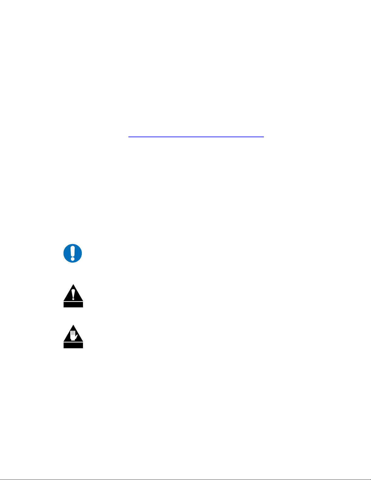
A typical interconnect diagram for the ROSS as deployed aboard ship in a mobile remote
satellite application is shown in figure 1. Please note that the example in figure 1 uses a generic
device name antenna control unit (ACU). All references to antenna controller unit (ACU) are
refer to vendor neutral ACU. See appendices for supported ACU types.
Comtech EF Data, Vipersat Products Page 9 of 87
Page 10
ROSS MN/13070
CISCO IP PHONE
7960
messages directories
12
ABC3DEF
i
settingsservices
45
JKL6MNOGHI
78
TUV9WXYZPQRS
0
#
OPER
*
Figure 1: Typical Interconnect Diagram
1.3 ROSS Control Function
The ROSS hosts a set of configuration, database, and map files that are used for controlling
satellite communications for the local remote terminal. This data provides the required reference
points for managing satellite handoff operations and for enabling/disabling the remote modem
transmitter. Shoreline boundaries provide a demarcation point for muting the modem transmitter
to prevent potential interference with fixed terrestrial or satellite systems.
Comtech EF Data, Vipersat Products Page 10 of 87
Page 11

ROSS MN/13070
1.4 Configuration Files
There are two system configuration files used by ROSS:
ROSS Configuration Files – A factory default
file holds the parameter values of the ROSS unit, which include parameters such as unit IP
address, ACU address, Modem address, VMS Multicast address and Network Identifier.
The default configure file only sets the factory unit IP address (192.168.254.3/24) leaving
all other parameters un-initialized, zero. Upon initial configuration the active configuration
file is generated and used during normal operations. If the restore factory defaults is
executed the active file is removed and regenerated with default configuration.
Note the password is stored directly to the system account utility (default “C
is only configurable through the console Telnet/Serial interface. If the password is lost or
unknown, the password can be restored through the local serial console interface which
does not require a login user name or password. Also factory resetting will restore the
password to default.
configuration file and an active configuration
omtech”) and
1.5 Database Files
There are four database files used by the ROSS:
Service Areas (SA) File – This is the primary database that provides critical information
about each satellite with which the local remote will communicate, such as the satellite
orbital position, TX polarization, frequency, bandwidth and identifiable description. These
set of parameters are sent to the ACU upon detected handoff points. The service area is
directly associated to service boundary and modem configuration files, which in
combination construct the communication area.
Shoreline Database File – This file contains the coordinates that comprise the shoreline map.
The SOTM system ensures that satellite transmission is strictly coordinated within a
configurable shoreline threshold expressed in Kilometers. When it is necessary to override
the global shoreline threshold, an override value can be specified in a Coordinated Area.
Coordinated Areas Map (CAM) File – This global database file defines those areas that call
for special transmission requirements. These areas serve as overrides, either negative or
positive, for enabling/disabling the modem transmit function. See section describing the
Ross Configuration Editor for more information on editing coordinated areas.
Service Boundary (SB) File – This file defines the geometry of a service coverage area
within the satellite footprint for the remote. Typically, multiple service boundary files are
stored on the ROSS, each corresponding to either a specific satellite or central hub with a
common satellite coverage area. Handoffs occur between service areas when the boundary
of the current service area is crossed.
Modem Configuration File – This file contains all configuration parame ters for the CDM-
570/570L & SLM-5650A base modem and IP Network Processor card. Typically, multiple
modem configuration files are stored on the ROSS, each corresponding to only one service
area location.
Comtech EF Data, Vipersat Products Page 11 of 87
Page 12
ROSS MN/13070
1.6 Features
The ROSS integrates storage capacity, location processing control with flexible interfaces in a
small hardware unit that is co-located with the mobile remote satellite station equipment (below
decks) with connections to the Comtech Vipersat modem (e.g., CDM-570L or SLM-5650A) and
the ACU.
1.7 ROSS Client Interface
The ROSS client interface is accessed using either remotely (Telnet) or locally using Serial
connections. The RS-232 serial connection is always running the ROSS client application and
requires no login account. This is the maintenance and operations console interface.
1.8 Storage Capacity
The ROSS offers generous non-volatile storage capacity that typically is not available in the
satellite modems. This capacity is used to store the large satellite foot print maps (approximately
1500), shoreline contour vector maps, exclusion areas, RF data, multiple modem configurations,
and other administrative information.
1.9 Processing Power
The ROSS provides its own CPU and software to implement the satellite roaming features,
constantly monitoring vessel position data, satellite signal, and management status in order to
determine if a satellite handoff is required. The ROSS CPU relieves the satellite modem from
having to perform the complex handoff task, thus eliminating any performance impact on the
modem.
Comtech EF Data, Vipersat Products Page 12 of 87
Page 13

ROSS MN/13070
1.10 Flexible Interface Platform
The ROSS offers a flexible hardware platform with standard interfaces, such as
10/100/1000BaseT, RS-232, and USB. These interfaces facilitate integration with multiple
vendor equipment, such as antenna controllers, for mobility services.
1.11 Event Log
The ROSS provides a system event log. The event log is a circular file capable of storing up to
511 events that may occur in the normal course of operation. Each event is identified with an
event type/category and time stamp, which is viewable and retrievable through the client or
ROSS Configuration Editor application. This file can be downloaded either locally or over the
air at any desirable intervals. The client user interface also provides a clear button to delete all
events refreshing the log file to known state.
1.12 Tracking Log
The ROSS provides a tracking log file to comply with FCC part 25.221(c), as the ROSS unit
must keep a log of vessel position and transmission parameters. The Tracking log is also a
circular file capable of storing up to 32766 entries or 455 days before overwrites take place. Each
entry is timed at 20 minute interval taking a timed/date snapshot of the vessels current location,
frequency, transmit status, data rates and modulations… It is expected that network administrator
will bulk download the tracking log file on scheduled intervals as not to lose any recorded
history. The ROSS Configuration Editor application provides a user interface to download the
reformatted tracking log as a coma delimited text file. Additionally a small simple command line
utility is available to automatically schedule file downloads assuming the vessel is in
communications with the central management hub facility.
1.13 ROSS Specifications
The ROSS is a network appliance server designed for rack mounting as a headless device (no
monitor, keyboard, or mouse). Utilizing a flash drive rather than a hard drive provides inherent
reliability. The following provides a list of system specifications that makeup the ROSS
hardware unit.
Server Components:
• CPU – Intel Celeron, 2.6 GHz, 1x 100mm blower fan
• Operating System – Linux 2.6.16.2 (Light Weight Kernel)
• RAM – 512 MB
• Flash Drive – 1 GB Disk-On-Module (DOM)
Front Chassis View
Comtech EF Data, Vipersat Products Page 13 of 87
Page 14
ROSS MN/13070
Front Panel:
Buttons
• Power On/Off button
• System Reset button
LED Indicator Lamps:
• Power LED
• Hard drive activity LED
• 2x Network activity LEDs
• System Overheat LED
LCD Keypad Interface:
• 16x2 illuminated LCD display
• Four navigation keys (up, down, left, right)
• Cancel Key
• Select/Enter Key
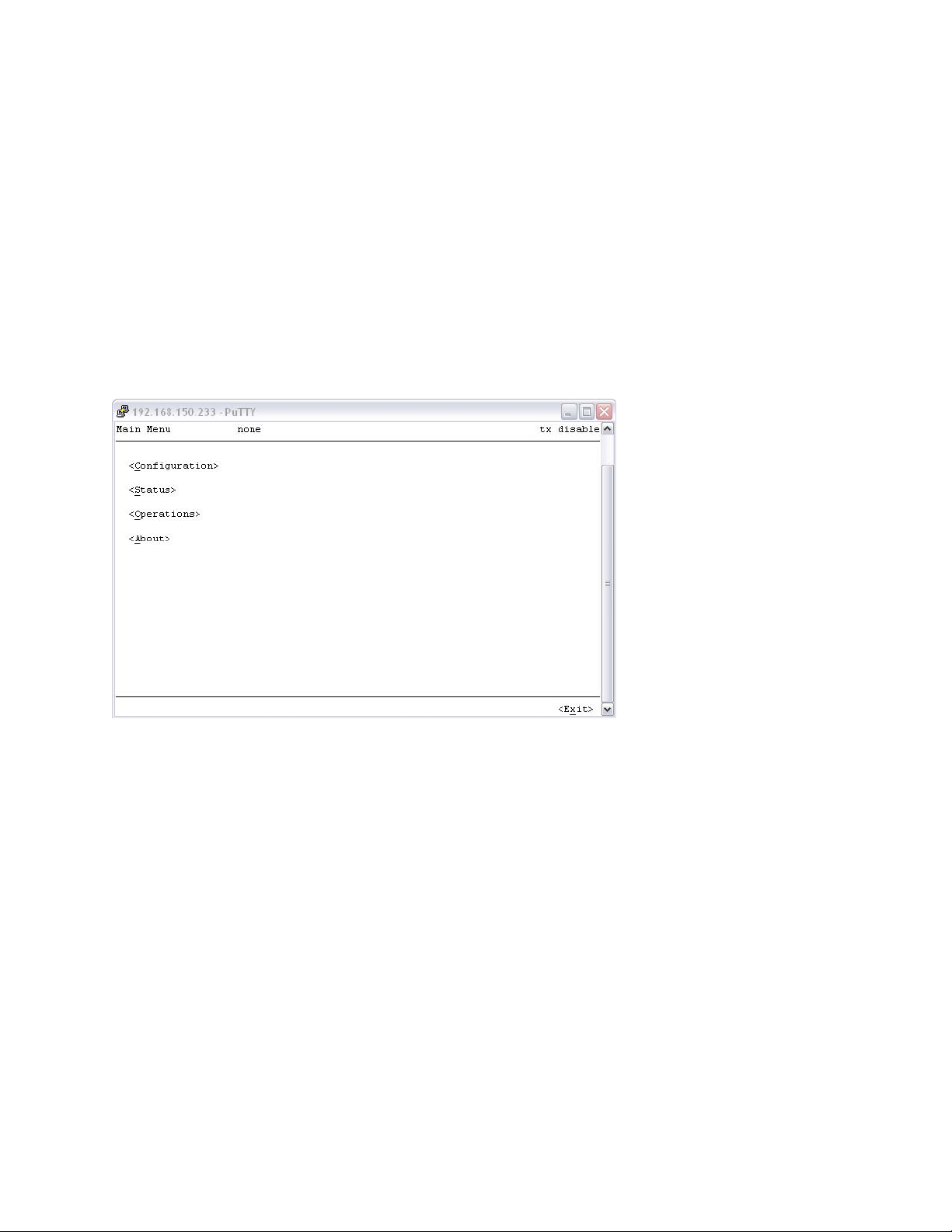
Rear Chassis View
Rear Panel Ports:
• 2x Network Interface – Ethernet 10/100/1000 BaseT, NIC 1, left port only used
• 1x RS-232 – Local Console, User Interface
• 2x USB – Re-Imaging or Upgrades
Operating Environment (ROSS System):
• Operating Temperature, 32° to 104°F, (0 to 40°C)
• Non-Operating Temperature, -40° to 158°F, (-40 to +70°C)
• Operating Humidity Range, 8 to 90% non-condensing
Power Supply:
• AC Voltage, 100 – 240V, 60 - 50Hz, 5Amp
Dimensions:
• 1U Rack Mount
• Height 1.7” (43mm), Width 16.8” (427mm), Depth 14.0” (356mm)
• Gross Weight 14lbs (6.4kg)
Comtech EF Data, Vipersat Products Page 14 of 87
Page 15

ROSS MN/13070
2 Installation Overview
This section provides the steps necessary to install the ROSS unit as part of the remote terminal
equipment in a Vipersat SOTM network. Any additional noncompliant third party equipment is
not described in this document for clarity.
2.1 Installation Requirements
The document assumes that the ACU and all its supporting equipment have been installed and
configured.
Hardware:
• ROSS Unit
• CDM-570L or SLM-5650A Satellite Modem & Router
• Installed ACU (including all below & above deck equipment)
Software:
• ROSS Configuration Editor, v1.3.0.921
• SetIP LAN Configuration Utility, v1.0
• VLoad 3.5.39 or later
• Putty v0.60
• ACU configuration application (depends on ACU vendor)
Documentation:
• ROSS User Guide, MN/13070, r4
• CDM-570/570L Installation and Operation Manual, MN/22125
• SLM-5650A User Guide, MN-0000035
• ACU Installation and Operation Manual, see vendor’s for part numbers
2.2 Unpacking and Inspection
Inspect the shipping container for any evidence of damage. If any damage is found, notify the
carrier in case a claim may have to be filed. This will only be necessary should the contents also
be found to be damaged.
Unpack the equipment from the container. Retain all shipping materials for future use, such as
for reshipment or RMA service. Visually inspect the equipment for any possible damage
incurred during shipment.
Check the equipment against the packing list to ensure that the shipment is complete. Should any
items be found to be either missing or damaged, contact customer support to report and record
before proceeding forward.
Comtech EF Data, Vipersat Products Page 15 of 87
Page 16

ROSS MN/13070
2.3 Installing the ROSS Unit
The ROSS is below-deck electronic equipment designed to mount flush in a standard 19-inch
equipment rack. Ensure that there is adequate clearance for ventilation, particularly on the top of
the unit. In rack systems where there is high heat dissipation, forced air-cooling must be
provided by top or bottom mounted fans or blowers. Under no circumstance should the highest
internal rack temperature be allowed to exceed 34ºC (95ºF).
Using a medium Phillips screwdriver, mount the ROSS in the designated rack space with four
rack screws. Always hand-tighten or use a low torque power driver to secure the front panel to
the rack rails. Note this is commercial grade manufactured equipment and it is recommended
that input AC power conditioning (online UPS) is provided.
2.4 ROSS, Modem, and ACU Connectivity
As shown in figure 1, the ROSS unit, MODEM (CDM-570L is shown in this example), and
ACU require several connections for data and signals. The installation and configuration of
the ACU hardware is beyond the scope of this document. Refer to the ACU vendor’s
documentation for more detailed information regarding ACU installation.
2.4.1 Ethernet LAN Connections
ROSS and the MODEM (CDM-570L shown in figure 1) communicate via IP over Ethernet LAN.
This is illustrated in figure 1, where the ROSS and MODEM are connected to an Ethernet switch.
The ACU must supports IP over Ethernet and ROSS supports IP for selected ACU, the ACU
should also be connected to the LAN. Any host equipment, such as PCs, IP phones, should also
be connected to the LAN.
2.4.2 Modem to ACU/Antenna
The Tx input and Rx output IF signals from the modem need to be wired to above-deck antenna
equipment such as LNB and BUC. In some cases, the Tx and Rx IF lines require connection to
the ACU sub-panel interface. The ACU installation manual should be referenced for specific
vendor information.
2.4.3 Modem Tx Mute and Rx Lock Signal
A majority of commercial ACUs use the Rx Carrier Lock as part of the closed feedback system
in the satellite acquisition mechanism. In other words, the ACU will aim its antenna until the
modem locks onto its configured carrier. It is also extremely important to correctly connect the
modem Transmit carrier muting signal from the modem to the ACU. This hardware control line
provides the overriding control to mute the transmit carrier over any other software logic. Tx and
Rx controls are shown in Figure 1 and identified “Antenna HW CNTL”. Consult the CDM
modem manual and ACU installation instructions provided by the ACU vendor for detailed
instructions.
Comtech EF Data, Vipersat Products Page 16 of 87
Page 17

ROSS MN/13070
2.5 Quick Start Configuration Checklist
In order to provision and configure ROSS, the check list is provided. The checklist assumes that
all the ACU hardware and wiring has been properly installed and configured.
Step Description
1 Build Service Area Information
2 Orbital Position,
Tx Frequency
Tx Polarization
Bandwidth
3 Create Service Bounds (polygonal areas). A geo-mapping application may be used
to layout the polygon and its coordinate points saved to a KML (Keyhole Markup
Language) file.
4 Create Coordinated Areas (polygonal areas). Coordinated Areas are optional.
5 Configure the CDM-570L or SLM-5650A modems for satellite service connectivity.
Once connectivity is established, take a snapshot of the modem configuration file
(.txt) using VLOAD. This .txt file will later be imported into each Service Area
entry. Create a .txt file for every satellite the modem will be switched to.
6 Follow the instructions section 6.1. Open a new ROSS configuration file and create
the Service Areas with the information previously collected.
7 Save the configuration file. This will be uploaded to ROSS.
8 Upload configuration file using ROSS default IP address.
9 Using Putty to access console interface or front panel LCD keypad, configure the
appropriate IP address, subnet, and gateway for the ROSS unit. Test ROSS IP
connectivity by pinging it from another host on the LAN, or logging into the ROSS
client interface.
10 If not done yet, use the RCE to upload the configuration file containing the Service
Areas. Verify that the Services Area was uploaded successfully by browsing the
Service Areas from the client interface or keypad interface.
11 Configure the ACU type and configuration fields.
12 Test ACU status by inspect the ACU poll status from Operations menu.
13 Verify ACU connectivity by examining the vessel position returned by ACU
14 Configure the IP address of the CDM-570L modem that ROSS is controlling.
15 Verify Modem connectivity by examining the modem poll status in operations
menu.
16 Configure Default Shoreline value in Operations menu.
17 Test Manual Satellite Handoffs by using Manual Handoff command from ROSS
client interface or front panel LCD interface.
18 Save the current ROSS configuration into the Active flash memory.
19 Reset ROSS and verify correct functionality.
Comtech EF Data, Vipersat Products Page 17 of 87
Page 18

ROSS MN/13070
2.6 ROSS System Overview
The ROSS server operates as a mediation device between the Comtech Satellite Modems and
Antenna Control Units (ACU) subsystem. Its primary role is to poll Global Positioning Satellite
coordinates (GPS) information from the ACU, determine the current location and push the
appropriate command/configuration files updating communication parameters. The ROSS unit
communicates to the modem and ACU on a network LAN interface connection using proprietary
IP protocols. Each unit’s IP address is programmed into ROSS starting a poll process which
gathers location, status and current configurations. As each units respond to the queried
messages the ROSS compares the received information to set database files making decisions to
mute carrier, change service area or continue to operate without interruption within the current
service area.
Service Areas are fundamental to the overall operation of ROSS as they contain control
information which is associated to three separate database/configuration files. Each service area
is configured with ACU set controls and linked to a Modem Parameter file, which are Service
Bound together through geographical operational fencing. The third element is the Coordination
Area Maps which are shared by all service areas. The overall fencing (binding) is geographical
longitude/latitude coordinates combined to create a closed polygon forming an operational area
or handoff boundary.
Through the polling of GPS coordinates from the ACU, ROSS processes hundreds of checks per
minute against the Service Area, Shoreline database, and Coordinated Areas. If anyone or all
represent a HIT, the ROSS initiates the proper action.
The ROSS server has four states that are processed during the course of initialization and
operation:
• Startup – Loading configuration and acquiring modem, ACU communications
• Normal – Normal operation mode assumes VMS connectivity in a service area
• Handoff – Detected transition to next service area
• Parked – No service area coverage configured
Startup
Startup is the first state the ROSS enters when the unit is powered or rebooted. During the startup
phase, the unit boots up the base OS, after system initialization the ROSS server is automatically
started by a watchdog script. This script is called from the OS and continually monitors the
ROSS running process. If the watchdog script fails process check, the ROSS process will be kick
started within 10 seconds. Boot time for ROSS server is approximately ~5 seconds, as a
complete cold start of the unit is ~25 seconds.
As the ROSS application is started the process loads configuration files, initializes internal
modules, and establishes communication with the modem and ACU. ROSS stays in this mode
until all devices are put into a known state by checking current location. If the current location
matches set service ID in the modem, no change is made dropping into normal operations.
Comtech EF Data, Vipersat Products Page 18 of 87
Page 19

ROSS MN/13070
If the check returns a difference and new service area is available the ROSS will initiate a
handoff sending configuration files to modem and ACU for processing of the next operational
location.
Note both modem and ACU must have valid status polls or ROSS will not initiate any service
area configurations.
Normal
This state is the “all systems are go” operating mode where connectivity to the hub is expected
because the vessel location matches a service area in the service boundary. Satellite Location
Identification Protocol (SLIP) messages and other management data is exchanged with hub
VMS, such as ROSS registration commands, modem status, and command messages. Tracking
Log entries are recorded in normal mode, and all other modes.
The transmission can be inhibited in Normal mode by:
a. ACU block signal is sent to the modem due to hazardous threshold (blockage limits).
b. Coordinated Area designates as no transmit zone
c. Vessel is inside a uncoordinated baseline (200km or set value, 0 = none, shoreline hit)
d. Carrier Inhibit, loss of hub carrier transmission, (receive data lock)
e. Modem or ACU no poll response timeout failure (~15sec) – TEK message initiated
f. Additionally the modem will mute transmit in the absences of TEK messages
Comtech EF Data, Vipersat Products Page 19 of 87
Page 20

ROSS MN/13070
Satellite Handoff Process
If the handoff state detects a transition point (new service area), the handoff function initiates the
following processes:
1. Disable Transmit – TEK message disabling modulator output power
2. Retrieve the new Service Area information
3. Pushes a new Modem Configuration Parameter file into modem
4. Send the command to ACU to point antenna to new satellite (Orbital Position,
Frequency & Bandwidth)
5. The modem will actively update all new parameters issuing a firm reset (quick
update)
6. Enable Transmit – TEK message enabling modulator output power
7. Enter Normal operating state waiting for modem to receive transmit grant message
from the hub
Note during this process the ROSS may send a TEK message enabling carrier before the antenna
has completed its tracking. In this state the ROSS relies on the hardwired transmit mute control
line from the antenna controller to the modem.
3.1 ROSS Messages & Data
3.1.1 Transmit Enable Keep-alive (TEK) Message
This TEK message is implemented as a watchdog process in the modem and is monitored for
transmit control change or absence status. If the modem detects the (absence) loss of 3 messages
(~15sec), the modem will fail poll reception timing out disabling modulator transmit. The ROSS
continuously sends TEK messages on 5 second intervals to the modem to reset the transmit
enable watchdog countdown timer. If the watchdog is not reset with a TEK message within the
specified interval, the modem will mute its transmitter until a TEK is received again.
3.1.2 ACU Commands
ACU commands typically use a proprietary message format. These commands are sent to the
ACU to reposition the antenna to new coordinates. ROSS sends Orbital Position, Frequency and
bandwidth to antenna control commanding it to resume tracking to new satellite location. The
ACU processes the orbital position into Azimuth and Elevation units calculated through the
current GPS coordinates. The frequency and bandwidth focuses the signal track algorithms on a
specific carrier typically the new service areas hub TDM carrier allowing the antenna signal
processor to peak on identified carrier. The modem demodulator lock signal is offered up to the
ACU through hardwire or soft-decision for final peak signal track and confirmation of satellite.
Comtech EF Data, Vipersat Products Page 20 of 87
Page 21

ROSS MN/13070
3.1.3 Modem Configuration File
This is a standard modem parameter file that is currently used by all Vipersat enabled Comtech
modems, such as the CDM-570L or SLM-5650A. It is a proprietary formatted text file. This file
contains configuration parameters that allow the modem to establish communications with a
specific satellite. In other words, each modem configuration file is created for a specific satellite
and hub ground station and contains all possible parameters values for the base modem and IP
router interface card. The Service Area database associates this modem configuration file with a
specific satellite and hub network. The file transfer uses the Comtech proprietary Streamload
protocol for ROSS to push a new configuration updates. Upon complete reception the modem
stores and processes the new changes issuing a firm reset to initialize the new changes. The new
updates are accomplished without a reboot minimizing the transitioning time.
Critical parameter categories include:
• RF properties such Tx and Rx home state frequencies, FEC rate, modulation, data rates,
and baseline transmit power.
• STDMA burst map configuration
• Route table configured for specific network topology if required
• QoS rules for setting unique priorities and bandwidth
Modem Parameters Excluded by ROSS:
• IP Address – Modem IP communication address remains static
• Network Node ID – Defines unique flow ID assigned by controlling VMS
Modem Parameters Replaced by ROSS:
• Satellite ID – derived by ROSS per service area
Exclusions and Replacements are necessary in providing seamless association between user
unknown values and possible unwanted overwrites. All the configurations for the modem are
stored in a single directory and are associated to its service area by sequential numbered file
naming convention.
Comtech EF Data, Vipersat Products Page 21 of 87
Page 22
ROSS MN/13070
3.2 Service Area Description
The Service Area (SA) is a container including all of the critical elements necessary to calculate
coordinated areas, determine operational or non-operational areas pushing updates and controls
to associated transmission equipment. The perimeter control within the SA is the Service Bounds
(SB) which is a multipoint polygon fence setting the satellite transmission beam area borders.
There are also Coordinated Area Maps (CAM) that if required can set transmit carrier zones
whereby the vessels transmit carrier is controlled to either enable or disable within these
boundaries. ROSS can store hundreds of these Service Areas that define the operating parameters
for each satellite and/or ground based equipment that the vessel requires for normal operation
within any given geographical location.
Each unique SA is created or maintained locally/remotely using the ROSS Configuration Editor
(RCE). The editor consolidates database elements into a single structure which is downloaded or
uploaded to the ROSS. The ROSS incorporates a file manger that labels each file element
through logical renaming appending each file with a sequential number grouping them all into a
SA. Example SA, the ACU command information sets the base reference with modem
configuration file(s), SB(s) which are then grouped together with a unique number. The SA
number is irrelevant to the user as it is assigned at the time of reception during uploads to ROSS.
The number assignment is only relevant to ROSS as container grouped database information.
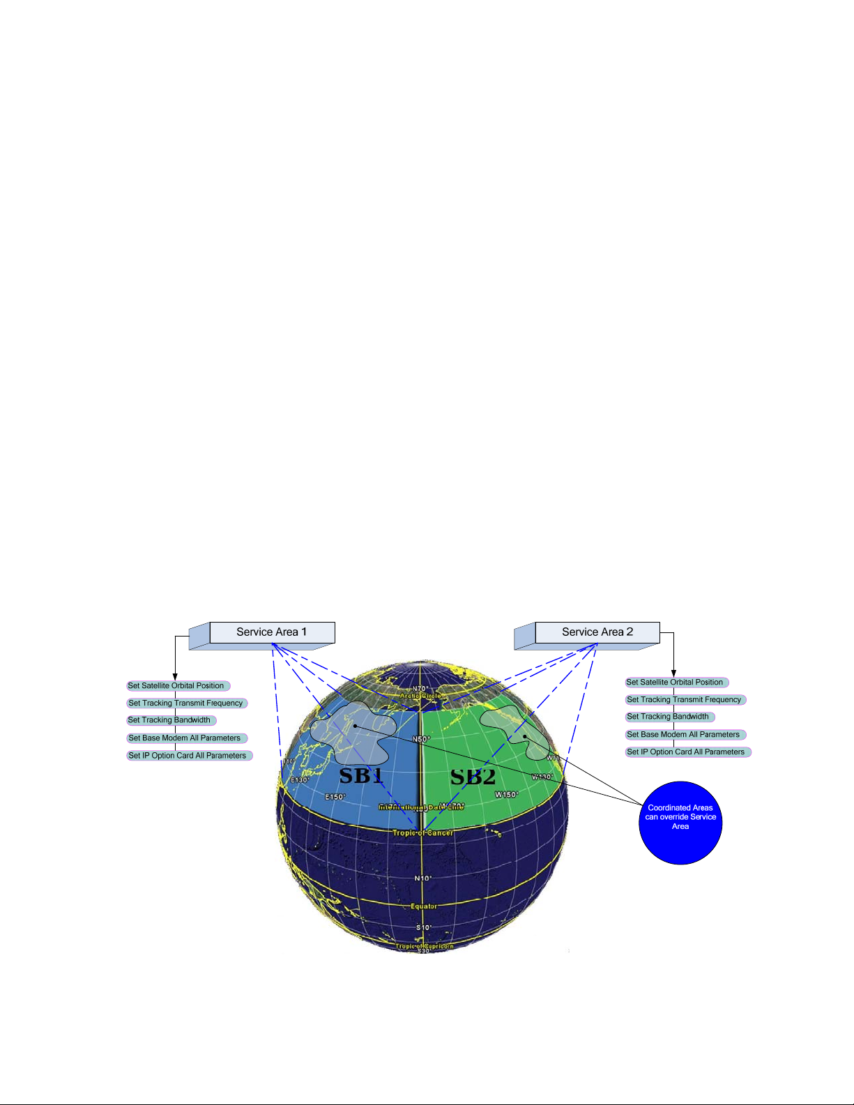
The SA example figure 2 depicts the structure of two separate SA binding list elements together
into a distinct area. This grouping is shown with only one SB per SA and two shared CAM’s,
however multiple SB’s can be linked into a single SA. Configuring SA’s is described in much
more detail in the Configuration section of this manual.
Figure 2: Service Area Example
Comtech EF Data, Vipersat Products Page 22 of 87
Page 23

ROSS MN/13070
3.3 Modem Interaction with ROSS
The Vessel equipment must bond together blending a mix of independent processes forming a
partnership of exchanged information and controls. This unique partnership builds a cohesive
system even though all run independent process. Each component has startup, normal and idle
modes of operation but still mesh together in timed acknowledged sequences.
The follow functional lists only describe the two Comtech units omitting the antenna control
system for lack of function detail. Each list is a step-by-step description on the basic processes
and how they interact forming the system functionality. This section describes what different
type of sequencing happens between cold and hot initializations.
3.3.1 Modem Initialization
The modem plays a key role in the communications chain as it must perform quickly through the
active transformation of pushed configurations file from ROSS. The modem has two different
modes of processing configurations files, one at boot time the other at run time. Each process
deferrers in sequence based on the initialization execution point.
Previously described the ROSS unit also has two types of execution points requiring long and
short initializations, however during the operational mode the ROSS unit pushes configuration
files to the modem which must be timed correctly for proper execution. During cold boot
(applied input power) all system components will typically complete initialization at different
times presenting a possible problem if the mediator (ROSS) pushed information too soon. ROSS
must wait for valid responses before sending controls or configurations prematurely resulting in
lost information. This validation before send eliminates repetitive processing streamlining the
initialization sequence.
Modem Cold Boot:
1. The Comtech modem stores two boot images, one is for the base modem processes and
the other is the IP Interface module (router). On power up both are loaded simultaneously
with base modem monitoring the boot state of the IP interface. The IP Interface module
boots the OS reading the FLASH parameter configuration file while the base modem
reads its last state values from NVRAM.
2. The Base modem first loads last state (stored) parameters which could have TX enabled,
however the transmit enable is held muted through a hardware control line from the IP
interface module until it completes its boot check before releasing. This prevents
premature transmission until the IP Interface has booted and finished rendering
configured states.
3. Once the IP Interface has finished booting it reads a stored parameter file from FLASH
sending two base modem configuration index scripts, Modem Group Configuration
(MGC) and Outdoor Group Configuration (OGC). These two loads contain the complete
IDU/ODU configuration sets.
4. Next the IP Interface loads Home State (subset of transmission values) parameters from
FLASH releasing the hardware mute signal.
Comtech EF Data, Vipersat Products Page 23 of 87
Page 24

ROSS MN/13070
5. Last the modem looks for demodulator lock following TEK enable and grant to burst
transmit from hub STDMA controller.
6. During the modem boot cycle ROSS is in the background trying to query the modem for
last set Satellite ID (service area). Once ROSS receives a valid response containing the
SAT_ID_NUMBER, a compare is applied to current location determining if a
configuration update is required.
7. If polled SAT_ID_NUMBER matches current location no change is necessary. If
different a new configuration file is push updating all communications parameters.
8. The TEK message now commences setting the transmit flag to enable mode.
9. The modem is now at home state waiting for TEK enable and hub grant to transmit
message.
10. During this time ROSS will send commands to the ACU updating the new pointing
location.
11. Special power controls can be applied to assure connectivity to the hub station during the
burst entry cycle. See STDMA Power Hunt.
12. After TX enable and burst grant the remote modem sends a request for registration to the
managing VMS. It must receive acknowledgment before transitioning through IP routing
table changes and dynamic switching to dSCPC mode. During this process all customer
data traffic is blocked and only allowing management traffic to pass. This prevents
possible customer switching requests from being lost during registration processing.
Note during the modem query the ROSS server is also polling the ACU for location status.
If the ACU has failed to respond during this initial sequence, ROSS will enter Parked
mode waiting for valid responses before changing states. Also during this process the
antennas tracking maybe inhibiting transmit until signal lock is established.
3.3.2 Modem Hot Initialization
All the same valid polling rules apply during hot initialization processing and are assumed to be
valid in the next sequencing.
1. During normal mode the modem operates under standard Vipersat control with only one
difference, the ROSS governs the transmit state. All standard dynamic switching, power
controls and communication recoveries apply.
2. If the vessel transitions into a new SA the ROSS server process the handoff sequence as
describe previously. However the modem is now in an operational state with all current
set value enabled.
3. As the ROSS unit processes handoff mode it pushes the new configuration file to the
modem via a UDP Steamload protocol.
4. The modem receives the file and checks the integrity before copying to FLASH and
processing.
5. The processing of the parameter file is accomplished on the fly inhibiting transmit before
execution. As the file parameters are processed through the internal menu engine each
value is modified/copied over. Once complete the Streamload process performs a firm
boot (execution time is in the ms) initializing all new values.
Comtech EF Data, Vipersat Products Page 24 of 87
Page 25

ROSS MN/13070
6. The modem is now at home state waiting for TEK enable and hub grant to transmit
message.
7. Special power controls can be applied to assure connectivity to the hub station during the
burst entry cycle. See STDMA Power Hunt.
8. After TX enable and hub grant to transmit the modem sends a request for registration to
the managing VMS. It must receive acknowledgment before transitioning through IP
routing table changes and dynamic switching to dSCPC mode. During this process all
customer data traffic is blocked and only allowing management traffic to pass. This
prevents possible customer switching requests from being dropped during registration
processing.
Note during the modem query the ROSS server is also polling the ACU for location and
status. If the ACU has failed to respond during this initial sequence, ROSS will enter
Parked mode waiting for valid responses before changing states. Also during this process
the ACU maybe inhibiting transmit until signal lock is established.
3.3.3 Transmit Power Controls
STDMA Power Hunt
Summary
The STDMA default power value is a possible problem as remotes with incorrect or impaired
transmissions cannot close their return links during service area entry mode. By adding a power
hunt algorithm with limits will provide burst link closure reliability.
The STDMA Power Hunt (SPH) function has a maximum power limit of up to 9dB in 3dB
increments greater than initial default, base value. This modulator power value cycles during
burst transmission increasing or decreasing power until it receives a reply from its managing
STDMA controller. This is accomplished through burst map acquisition acknowledgement flag.
Throughout the process the remote will remain at base or modified set power value until
commanded otherwise or manual operator intervention. Once in SCPC mode and DPC enabled,
the value is over written by DPC and servos to targeted set Eb/No value. Any revert from SCPC
to STDMA will reuse last set DPC value as power delta offset over default set-point. Reboot or
forced revert will cause the unit to clear all temporary set power values.
Implementation
The hub and remote units both provide a role in SPH which allows the remote modulator to
increase its base configuration (Home State) power setting to a maximum of 9dB from initial setpoint if link reception is incorrect or impaired. The hub STDMA burst map contains a flag which
is used separately by each remote in the group. This flag indicates if either their burst ACK
message was missed or received at the hub. When the hub STDMA controller receives a valid
burst ACK from the remote it sets the flag for the corresponding remote in the next burst map
indicating completed transmission.
There are two counters initialized in the remote, one that reads missed ACK’s and the other is
received ACK’s.
Comtech EF Data, Vipersat Products Page 25 of 87
Page 26

ROSS MN/13070
During burst map reception the remote reads the ACK flag and either increments or resets
missed ACK counter. The missed counter is initialized and invoked when the first or next
message received has the flag set to zero ‘0’. It then starts a 10 missed count before incrementing
the power value by 3dB step. The second counter is received ACK’s which has a flag set to
‘1’and the count must receive 5 consecutive good ACK’s before resetting missed ACK counter.
Once reset the power hunt stops and the value is retained and put into a variable called DPC
Delta.
There are three separate stored power components, Baseline Power, DPC Delta, and SOTM
Offset. Note SOTM Offset is a reserved variable for future use.
Baseline Power is either Home State default power value which is applied at initialization, CLI
force home state or VMS force reverts or the last value received from VMS. The baseline power
value is based on link budget calculations which may be subject to error in SOTM environments.
DPC Delta is a shared value between SPH and DPC. SPH applies its offsets during STDMA
mode only, while DPC adjustments are made in SCPC only due to environmental conditions,
unknown budget calculations (ocean coverage errors) and also traveling through power variances
within a satellite beam. These two power offsets share this variable with only one exception DPC
can overwrite the SPH value.
Operational Conditions
When enabling SPH it is only available in STDMA. Switching to SCPC disables this
function allowing DPC to modify independently. However, the SPH value remains stored in
DPC delta variable unless over written.
Once set the delta value remains effective throughout switching states, SCPC or STDMA
unless overwritten by DPC.
The current SPH gets stored in the DPC delta variable for use in SCPC mode and STDMA
during reverts (Home State). It is cleared during a force revert, either from VMS or CLI.
There are two counters, missed ACK and other is received ACK’s.
SPH power is an incremental 3dB step value (added or subtracted) up to 9dB after 10 cycles
(burst maps) of missed ACK’s.
The missed ACK counter is cleared after receipt of 5 consecutive received ACK’s.
Boot & Initialization: (burst transmission succeed)
1. The default Home State power value is applied to the base modem modulator on boot-up.
2. After transmission grant, remote bursts to corresponding STDMA controller with ACK +
Registration request message.
3. If hub reception is NOT impaired and transmission acquisition is completed the burst
controller sets the missed ACK flag to ‘1’ indicating to corresponding remote good burst.
4. No power adjustment is required. “SPH value remains at zero value”
5. VMS responds to registration request sending registration configuration to remote.
Comtech EF Data, Vipersat Products Page 26 of 87
Page 27
ROSS MN/13070
Boot & Initialization: (burst transmission failure)
1. The default Home State power value is applied to the base modem modulator on boot-up.
2. After transmission grant, remote bursts to corresponding STDMA controller with ACK +
Registration request message.
3. If hub reception was impaired and transmission acquisition failed the burst controller sets
the missed ACK flag to ‘0’ indicating to corresponding remote failed burst acquisition.
4. Power adjustment is required.
5. Remote missed ACK counter is initialized waiting next burst map and flag set value.
6. If count reaches 10 (burst maps) missed ACK’s the default power is increased by 3dB.
7. If next burst map indicates received ACK, the missed ACK counter holds count until 5
consecutive receive counts.
8. After 5 consecutive receive counts the missed counter is reset and the power value is
stored in DPC Delta variable.
9. VMS responds to registration request sending registration configuration.
10. Remote may now switch to SCPC mode.
Note all stated power process assumes receive transmission from the hub TDM is good.
4.1 ROSS Client Interface
The ROSS client interface is accessed using either Telnet or Serial connections through an open
source application, Putty. The RS-232 serial connection is always running the ROSS client
application and requires no login account. This serial interface is used for local maintenance
configuration management such as resetting login passwords or unit IP address.
The ROSS client interface is accessed by Putty, an open source Windows application. Putty is a
Win32 Telnet client configurable for either serial or LAN IP communications.
Comtech EF Data, Vipersat Products Page 27 of 87
Page 28

ROSS MN/13070
4.2 Connecting To ROSS via Serial Interface
This connection is the initial interface that provides open account access requiring no login
password to establish communications to the main menu system. Through this interface allows
the installer or operator to setup the basic communications parameters, e.g. unit IP address,
subnet mask and gateway address. It’s also the backdoor interface if in the event the login
password was forgotten or resetting of the network IP address is required.
Upon initial configuration (out of box) all parameters are set to factory values initializing only
minimal settings for basic boot operations. It’s only necessary at this point to set a subset of
communication parameters as the full configuration is handled by a separate Comtech
application “ROSS Configuration Editor”.
1. Connect a RS-232, DB9-F-F crossover cable between PC and ROSS serial interface
connections.
Figure 3: Serial connection to access ROSS client interface
Comtech EF Data, Vipersat Products Page 28 of 87
Page 29
ROSS MN/13070
2. Apply input AC power to ROSS and push the front panel power button to boot ROSS.
Boot up requires approximately 25 seconds.
3. On the PC launch the Putty application clicking on the desktop ICON or from sourced
directory location.
4. Configure communications for serial, COM1 or available port# and port speed of
115200.
5. Click Open button to establish communications.
6. It will be necessary to refresh the window display text, select F12 on the PC keyboard.
4.3 Connecting to ROSS via LAN (Telnet) Connection
This connection interface is used for local LAN or remote control over the satellite
communications link. It operates using the same Putty application with a different setup
configuration. It is possible to establish local communications without initially configuring the
network interface IP address in the event that a serial cable is not available.
Each ROSS unit uses a factory default IP address and mask: “192.168.254.3/24”. When
configuring ROSS with its default IP address, any host IP address must be configured to be
within the 192.168.254.0 subnet.
Note it extremely important to ensure that the correct IP address is assigned. An incorrect
address may cause the ROSS unit to be unreachable from a remote host.
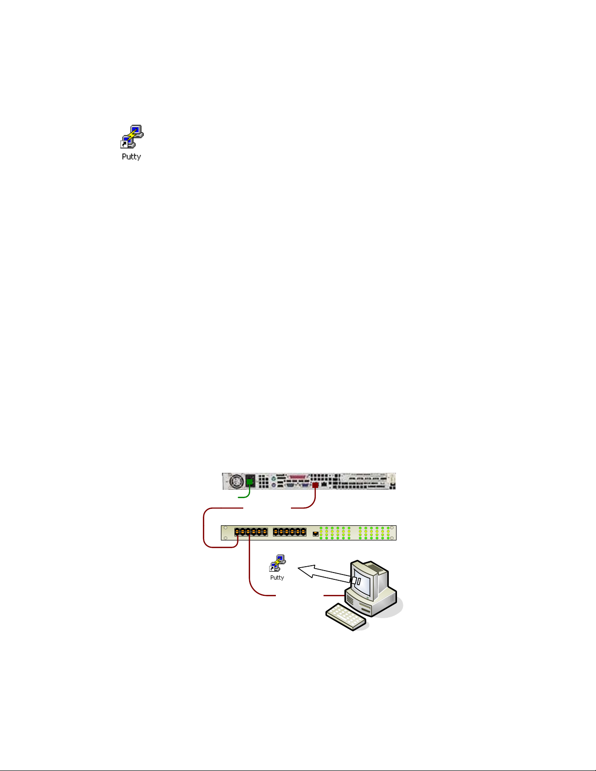
1. Connect the CAT5 cables as shown below, note if an Ethernet switch is not available
use a crossover LAN cable between ROSS and PC.
Default - 192.168.254.3/24
ROSS
110/220 VAC
LAN 10/100BaseT
Ethernet Switch
PC
LAN 10/100BaseT
`
Set - 192.168.254.100/24
Figure 4: Ethernet LAN connection to ROSS client interface
Comtech EF Data, Vipersat Products Page 29 of 87
Page 30

ROSS MN/13070
2. Apply input AC power to ROSS and push the front panel power button to boot ROSS.
Boot up requires approximately 35 seconds.
3. Next on the PC configure network communication to operate within ROSS IP subnet
address range. See your Windows operators guide for settings of network properties.
4. On the PC launch the Putty application clicking on the desktop ICON or from sourced
directory location.
Configure the Putty settings to match the ROSS default IP address or networked
configured.
Enter default
“192.168.254.3 or
network assigned
IP
address
Under Connection,
verify that the
Return key sends
setting is unchecked
5. Click Open button to establish communications, at the login prompt enter “admin”
and default password as “Comtech” or set password.
There is a second method to configure the IP address of each ROSS unit, which is by a
Comtech utility (LAN CFG – SetIP) that provides a unique Ethernet messaging exchange.
This small Windows application broadcasts a proprietary packet which all ROSS unit’s
listen for and respond with MAC, IP and version information. See Appendix E for more
information.
Comtech EF Data, Vipersat Products Page 30 of 87
Page 31

ROSS MN/13070
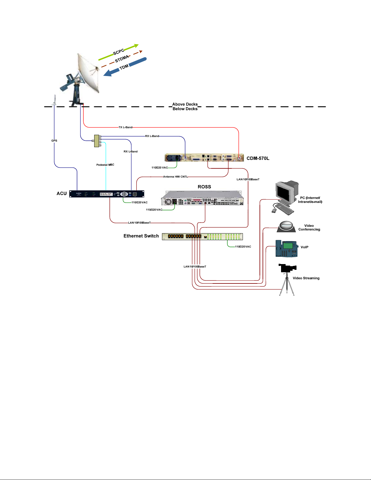
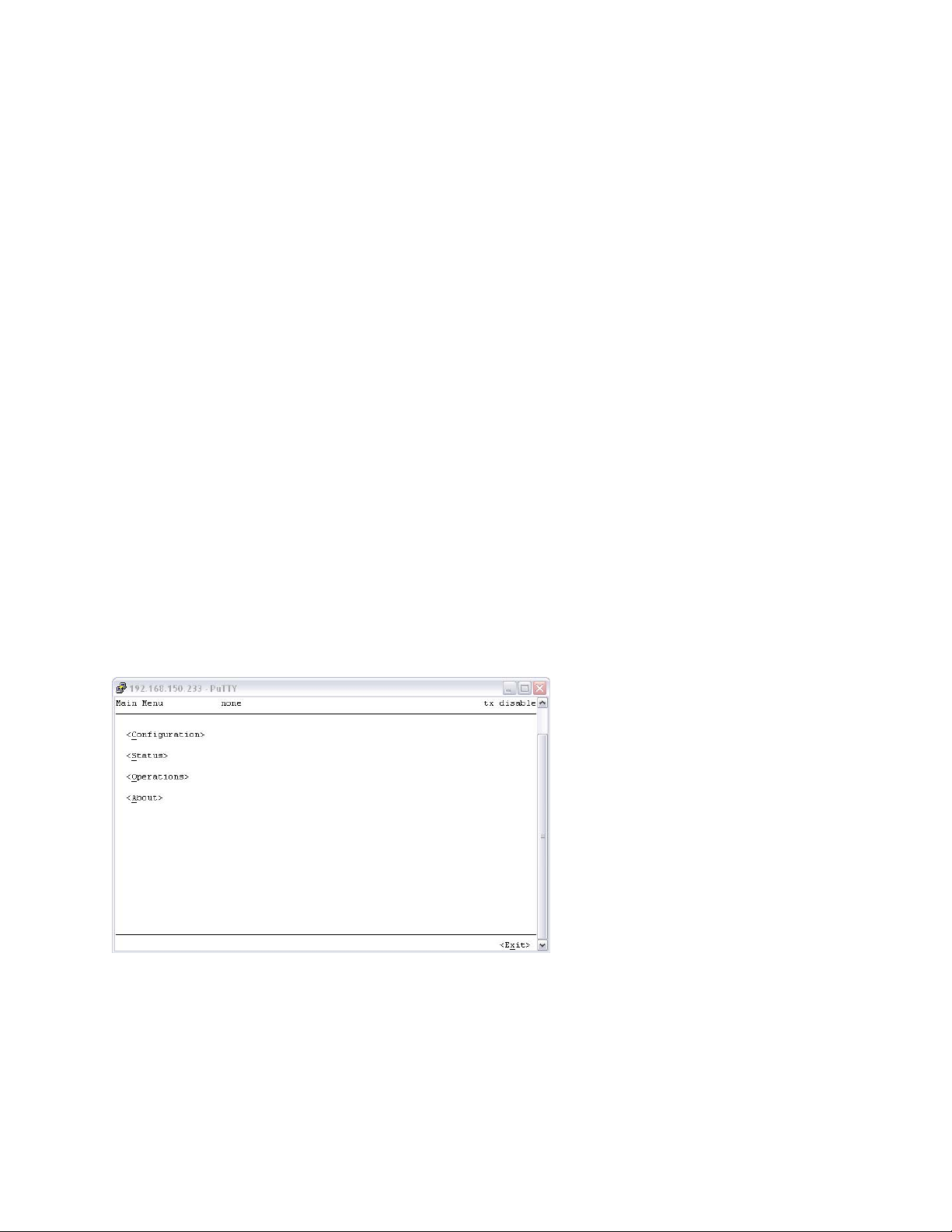
4.4 Main Menu
After using one of the connection methods the top main menu will display configuration, Status,
Operations and About selections. Each selection has submenus which provide additional
configuration settings or system information. The menu using Putty allows left mouse button
selection or keyboard character shortcuts with keypad arrow manipulation. All settings require
positive acknowledgements before they are stored into nonvolatile memory. The shortcut keys
are represented by an underlined character on each displayed menu.
This section is a step-by-step procedure configuring all the necessary communication parameters
for ROSS to gain access control to system components e.g. network, modem and ACU. These
settings are typically configured once during installation deployment and remain static unless
network configuration change.
4.5 Configuration Menu
Select Configuration to access the configuration menu. The configuration menu has specific
communication parameters that ROSS will use to query and control. The base menu bar sets
storage parameter controls as illustrated below:
4.6 ACU Configuration
Every ACU vendor has their own proprietary communication protocols that provide for external
devices to gain access to monitor and control settings. Selecting ACU Type allows the operator
to enter the appropriate model or manufacture indicating to the ROSS which device driver to
initialize during boot-up. The ACU models supported by ROSS are listed in Appendices at end
of this document. The ACU C
configuration options.
See the Appendices for ACU specific configuration parameters.
Comtech EF Data, Vipersat Products Page 31 of 87
onfiguration dialog allows the operator to sets the ACU type and
Page 32

ROSS MN/13070
S
ave - All Changed Parameters
R
evert - Last Changed Parameters
Reset - Restore System to Factory Settings
1. Enter ACU type string. This is specific to each ACU vendor. See appendices for more
information.
2. Enter the ACU Config using the format for the specific ACU vendor.
3. Select Ok to enter changes, Cancel will disregard entries
4.7 Modem Configuration
This sets the IP address that ROSS will use to communicate with the locally attached Comtech
modem. The modem IP address information is obtainable from the front panel of the modem, see
specific users guide for menu operation. After selecting O
inquires of modem SOTM mode, enabled/disabled and set SAT ID number.
k the ROSS will initialize polling with
Comtech EF Data, Vipersat Products Page 32 of 87
Page 33

ROSS MN/13070
4.8 Network Configuration
The network configuration is the ROSS system LAN interface properties setting the IP address,
subnet mask and local default gateway. After applying the network protocol stack will
reinitialize with the new IP settings without rebooting.
During the address change the top menu will display “A timeout occurred processing your
request!” This is normal as services have temporarily stopped during address reset.
4.9 Network ID
The Network ID that is assigned to the unit defines which network within the managing VMS
that the ROSS information will belong. All ROSS units used in a specified network will have the
same network ID. This parameter is used by the VMS to identify units common to a network and
allows the VMS to manage multiple networks, each with its own unique network ID number.
This value is configurable from 1 -255 and is assigned by the network operator. Zero equals no
network assignment.
4.10 VMS Multicast Address
This sets the listening address of the active managing VMS. The VMS sends announcement
messages to specified address to update active managing VMS where redundancy applies.
Comtech EF Data, Vipersat Products Page 33 of 87
Page 34

ROSS MN/13070
4.11 Shoreline Default (Threshold)
This sets the global shoreline threshold value. The FCC for the US shoreline is required to cease
transmission at 200.0 kilometers from shore. If a vessel’s distance to the nearest shoreline is less
than or equal to the threshold, and NOT inside an enabled coordinated area, ROSS will mute the
satellite modem’s transmitter. The shoreline threshold can be disabled by setting to 0. The
shoreline value is a decimal value representing kilometers. Coordinated Area Mapping can be
used in place or in conjunction to control transmit. See Coordination Area Configuration for
more information.
4.12 Change Console Password
Enter the new console password with a minimum of 6 to a maximum of 22 characters. There
must be at minimum either one upper or lower character, all other character sets are acceptable.
Note the password is stored directly to the system account utility (default “Comtech”) and is
only configurable through the Telnet/console interface. If the password is lost or unknown, the
password is only configurable through the serial interface which does not require a login
account. Factory resetting will restore password back to default.
4.13 General Setup: Date & Time
Setting the date & time is the users local time reference. All logged events use GMT as the
vessel will travel through different time zones. Enter the date & time as shown below.
Comtech EF Data, Vipersat Products Page 34 of 87
Page 35

ROSS MN/13070
4.14 Unit Status Page
The status page shows the communication state of the modem, ACU, last reported position,
transmit condition and ROSS unit up time. All displayed value requires manual Refresh to query
the latest information or you can select Automatic where the values are updated every 5 seconds.
The top status bar is automatically updated with the current service area/service bound and
modem transmit statue. There is also a Reset that will clear the ACU and Modem Status resetting
to zero state, starting both polls at 1/1.
Top Status Bar
Automatic
Refresh Status
4.15 Transmit Status
On the top menu bar right side indicates ‘enable’ or ‘disable’ of the set value in the TEK
message sent to the modem. The enable indication may not be the true state of modulator
transmission because of external controls, e.g. ACU hardware control signal or modem internal
logic that can override ROSS. This value ‘enabled’ represents that ROSS is in a valid service
area and communication poll status of modem an ACU are successful. If disabled the modulator
transmit carrier is muted regardless of any other controls.
4.16 Last Position
This position retrieved from the most recent ACU poll. This value is expressed in longitude and
latitude in decimal degrees. If the reported position is within a coordinated area, the coordinated
area ID will be displayed adjacent to the coordinates. ROSS polls the ACU for position on a 5
second interval. This value is updated by the Refresh command.
Comtech EF Data, Vipersat Products Page 35 of 87
Page 36

ROSS MN/13070
4.17 Heading Position
This position retrieved from the most recent ACU poll. This value is expressed in decimal
degrees. ROSS polls the ACU for position on a five 5 second interval.
4.18 Handoff Mode
The ROSS Handoff Mode is defaulted to automatic mode (satellite handoff is triggered by vessel
position within Service Areas) on startup. If Force Manual Mode is invoked, Automatic Handoff
mode is disabled. Automatic Handoff mode can also be enabled or disabled. When Automatic
Handoff mode is disabled, the modem will continue to transmit except if it enters a coordinated
area with a transmit flag set to disabled. On power up Automatic Mode is always enabled.
4.19 Stealth Mode
If enabled, ROSS will omit any location information in the Satellite Location Identification
Protocol (SLIP) message. Some modes of operation require location of vessels to remain
unidentified from network operators. This mode can be enabled or disabled from the Operations
menu in the ROSS client console.
4.20 Last Poll
This indicates the last poll time at which the ROSS queried the modem and ACU for status
display updates, approximately every 5 seconds.
4.21 ACU Status
The ACU status is the number of failed or successful poll attempts from start of ROSS server or
from last Reset. A percentage is calculated from the count differences between failed or
succeeded attempts. If failed attempts are equal 100%, check communications between ROSS
and ACU. Note if status is indicating failed the modulator transmission is muted.
4.22 Modem Status
The modem status is the number of failed or successful poll attempts from start of ROSS server
or from last Reset. A percentage is calculated from the count differences between failed or
succeeded attempts. If failed attempts are equal 100%, check communications between ROSS
and modem. Note if status is indicating failed the modulator transmission is muted.
4.23 System Up Time
This shows the operating time of the ROSS server since last boot time.
Comtech EF Data, Vipersat Products Page 36 of 87
Page 37

ROSS MN/13070
4.24 Managing VMS
The active managing VMS sends an address announcement multicast message on timed intervals
containing its source IP address. This address is used by all listening units that match the
multicast address within the specified network. After reception of the active managing VMS
announcement multicast message, the then ROSS process the information and sets the VMS
destination IP address wherein to send unsolicited information. This address may change if there
is server alteration either through redundancy switchovers or administration of new IP address
network plan.
4.25 Operations Menu
The operations menu is used for performing common functions while the ROSS unit is
operational. These operations include maintenance tasks such as viewing event logs, or
enable/disable specific options that affect handoff, and most importantly, invoking a manual
handoff
4.25.1 Set Handoff Mode
This parameter is typically used for vessel commissioning allowing the installer to test basic
operations between service areas if possible. Additionally if the network operator or on-board
attendant determines that automation must be terminated during installation/test mode or vessel
in nonoperational state.
Comtech EF Data, Vipersat Products Page 37 of 87
Page 38

ROSS MN/13070
The View Service Area explained in the next section allows manual handoff selection and if
invoked will disable this automatic feature. After exercising manual handoffs from the service
area menu, this handoff mode control will require setting back to automatic if forced to manual
mode.
The handoff mode is set to automatic at boot-up to insure that at worst case if an operator was
performing maintenance procedures and forgot to return the setting back to normal condition, the
local attendant could restore automation by simply power cycling unit.
4.25.2 Stealth Mode
When Stealth mode is enabled, the vessel position is omitted from the periodic status message
(SUM/SLIP) sent to the managing VMS. The vessel position is still recorded in the ROSS’s
internal tracking log. Stealth mode is disabled by default.
4.25.3 Service Area
This menu provides a list of configured service areas that were configured using the ROSS
Configuration Editor. Each listed SA is assigned an ID displaying satellite orbital set position,
Transmit polarity and targeted carrier formation. The complete definition and configuration of
service areas are described in section 5.0, ROSS Configuration Editor.
Manual Handoff
command
Comtech EF Data, Vipersat Products Page 38 of 87
Page 39
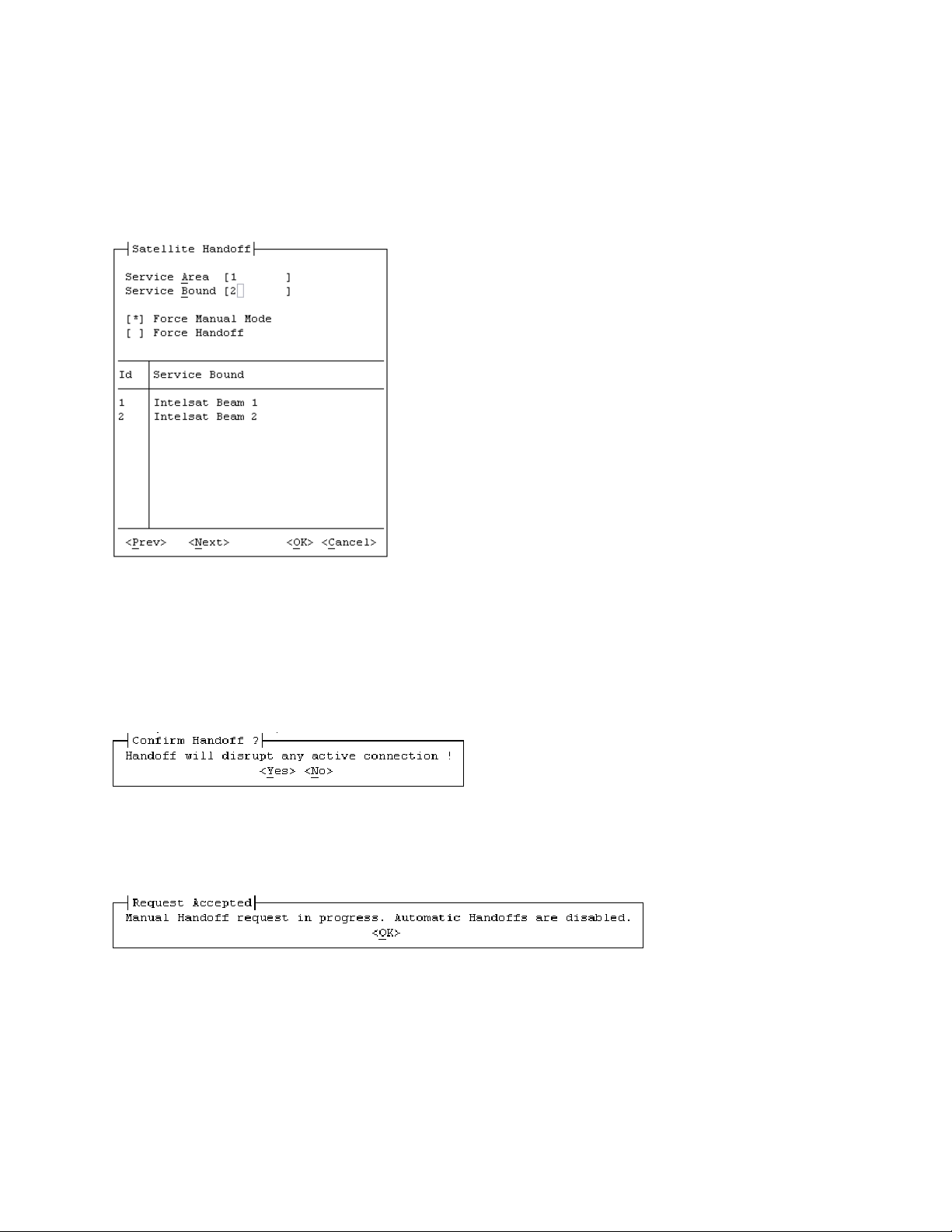
ROSS MN/13070
4.25.4 Manual Handoff From Service Area
The Service Area handoff command is useful when it becomes necessary to test or force the
modem to a different satellite. To Force a Handoff of a selected service area, click on Handoff
from the bottom of the menu and enter desired Id from the list of service areas.
After entering the desired service area Id number from the list, a second list of all the Service
Bounds contained in the SA is displayed. Enter the Service Bound Id number from the displayed
list. Next select Force Manual Mode if the SA Id is outside the currently detected. Or exclude
Force Manual Mode and select Force Handoff if the SA Id is within the currently detected.
Click <OK> to start the Manual Handoff operation.
A confirmation dialog is displayed to request Yes or No before proceeding. If the operation is
confirmed the dialog below is shown to the operator indicating that the automatic handoffs are
disabled.
After making a selection ROSS will override current location pushing selected SA configurations
to the modem and ACU. Once completed, the manually requested SA description will be
displayed at the top on the menu indicating selection completion. You can at anytime during this
process select a different SA for execution without adverse effects.
Comtech EF Data, Vipersat Products Page 39 of 87
Page 40
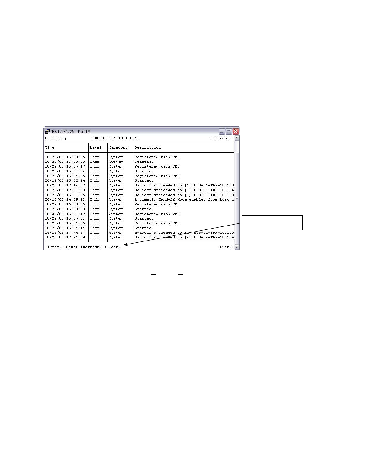
ROSS MN/13070
Force Manual Mode disables Automatic Handoff Mode. To restore Automatic Handoff mode,
where ROSS performs a handoff based on vessel position and service area, use the Handoff
Mode command described in section 4.25.1.
4.25.5 Event Log
Upon boot the system records internal processes and events that are useful when troubleshooting
failure conditions and improper operations. The even view is a scrollable window sorting oldest
to latest events.
Event navigation
There four menu controls at the bottom of the window frame that provide navigation through the
list of stored event. By selecting Next or Prev the list will block scroll between events.
The Refresh will update list and the Clear selection will delete all events emptying the file
completely.
Each event is identified with an event type/category and time stamp and recorded with a brief
description. The total list is a circular file capable of storing up to 511 events that may occur in
the normal course of operatio
n. After reaching the max list count the oldest event will be replace
with the next newest event.
If stored history of system events is required for local or remote backups, the file can be
downloaded either locally or over the air at any desirable intervals using the supplied utility
“GetLog.exe”, which is run from a command-line prompt with the capability of setting up
windows scheduled inte
ction 6 Get Log Files.
se
rval downloads. For more information on GetLog application see
Comtech EF Data, Vipersat Products Page 40 of 87
Page 41
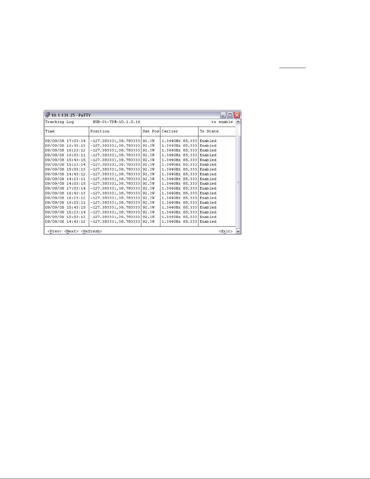
ROSS MN/13070
4.25.6 Tracking Log
The Tracking log is also a circular file capable of storing up to 32766 entries or 455 days before
overwrites take place. Each entry is timed at 20 minute interval taking a timed/date snapshot of
the vessels current location, frequency, transmit status, data rates and modulations. It is expected
that the network administrator will bulk download the tracking log file on regular intervals so as
not to lose any tracking data.
If stored history of tracking information is required for local or remote backups, the file can be
downloaded either locally or over the air from the ROSS editor or at any desirable intervals using
the supplied utility “GetLog.exe”, which is run from a command-line prompt with the capability
of setting up windows scheduled interval downloads.
For more information on GetLog application see section 6 Get Log Files.
Comtech EF Data, Vipersat Products Page 41 of 87
Page 42

ROSS MN/13070
4.25.7 Reset Unit
The event that the operator determines that reset of ROSS application is require there are three
separate reset functions available.
Reinitialize all currently configured active settings
Forces the ROSS server application to restart
Execute a full system shutdown and restart of all Processes
4.26 ROSS Front Panel Interface (Keypad/LCD)
The ROSS units have a front panel interface consisting of a six-function keypad and 16x2
character LCD display. The Front Panel interface allows for local maintenance of the ROSS unit.
Any configuration and operation function provided in the console interface (sec 4.1) is available
from the front panel interface.
This keypad interface is based on a structured menu system where the keypad is used for menu
navigation, data entry, and command execution. The “Select” button (green check) is used to
select items on the menu display. The “Cancel” button (red X) will cancel any operation or move
to the upper menu level.
Navigation from one menu item to another is accomplished by using the arrows keys to move the
cursor (flashing block) to the desired item. Pressing the “Select” button will execute the
command or menu item identified by the cursor position.
Figure 5: LCD screen and keypad layout showing splash screen
This initial splash screen displays the transmit status and the current service area id and service
bound id (in parentheses) being used.
The Keypad interface uses a multi-level menu tree to expose the commands and functions. The
root level menus and their sub-menus are shown below. The menu structure closely matches the
menu in the ROSS console interface described in Section 4.1.
Comtech EF Data, Vipersat Products Page 42 of 87
Page 43

ROSS MN/13070
At root level, there are four sub-menus.
Root Menu
Configuration Root
Status Panel (Service Area is first item)
Operation Root Menu
About display
Menus: Config, Status, Operation, About
Each sub-menu may display commands or more sub-menus to show more categories.
Comtech EF Data, Vipersat Products Page 43 of 87
Page 44

ROSS MN/13070
4.27 Configuration Menu
The Configuration menu has five sub menus as shown below:
Configuration Root
Unit Configuration Top Level
Interface Configuration Menu
VMS Configuration Menu
Shoreline Override dialog
System Configuration Top Level
ACU Configuration Top Level
ACU Type Information
Modem Configuration Top Level (IP address)
ACU Communication Information
Comtech EF Data, Vipersat Products Page 44 of 87
Page 45

ROSS MN/13070
Utilities Top Level
Save Configuration to Flash
Load Configuration from Flash
Restore Factory Configuration
4.28 Status Menu
The Status menu item is a command that allows the operator to scroll through twelve (12)
separate status items. The “Left” and “Right” navigation keys scroll to next and previous status
item views.
Current Service Area
Transmit Status
Last Position Longitude - reported by ACU
Current Heading - reported by ACU
Handoff Mode Automatic or Manual
Comtech EF Data, Vipersat Products Page 45 of 87
Last Position Latitude - reported by ACU
Stealth Mode Enabled or Disabled
Page 46

ROSS MN/13070
Time of Last Poll to ACU and Modem
ACU Poll Response and Status
Modem Poll Response and Status
System Up Time
IP Address of Managing VMS
4.29 Operation Menu
The Operation menu item exposes commands to change Handoff Mode, Stealth Mode, Reset unit,
browse event & tracking logs, and view the current Service Area entries. It also allows the user
to perform a manual handoff to a specific service area.
Operation root menu
Utilities sub-menu
Selecting “Service” command allows the user to browse the Service Areas described in
section 4.4.3. The “Left” and “Right” keys display the previous or next column in the current
row entry, while the “Up” and “Down” keys display the previous or next Service Area entry.
Each Service Area entry has the following data items. Select the “Enter” key will invoke a
manual Handoff Command. If successful, Automatic Handoff mode is disabled.
Comtech EF Data, Vipersat Products Page 46 of 87
Log sub-menu
Page 47

ROSS MN/13070
Service Area ID
Satellite Position value sent to ACU
Polarization Value:
Depending on the ACU type, this value can also specify Rx Polarization
Carrier information sent to ACU for acquisition
Service Area description or label text
4.29.1 About Menu (command)
The About menu command displays information about the current ROSS software version and
build date. The version shows the software levels major, minor, maintenance and build level.
Comtech EF Data, Vipersat Products Page 47 of 87
Page 48

ROSS MN/13070
5 ROSS Configuration Editor
To complete the configuration of ROSS it is required to generate a unique service area (SA) with
all its associated files. The ROSS Configuration Editor will help gathers different elements and
consolidates them into a single structure which is uploaded to the ROSS file manger. The ROSS
Configuration Editor also provides the capability for file uploads and downloads either through
local LAN or over the air interface.
ROSS is ready to accept roaming database files after completing the basic communication
configurations in Section 4 “Communications Configuration”. The screen capture below
illustrates as if two SA were generated and possibly uploaded. This section will step through the
basics of creating a complete SA files for first time upload. It will also touch on editing an
existing file structure for ongoing maintenance.
The ROSS Configuration Editor (RCE) is Windows application that is launched directly as a
standalone program requiring no system installation. It can be run from anywhere within your
network assuming the PC executing the program has IP connectivity to the editing ROSS unit(s).
The RCE is executed by double clicking on the program ICON shown below.
The RCE uses a proprietary IP protocol to transfer the configuration data in optimized manner.
The UI provides pull down menus as well as tool bar icons for configuration operations.
5.1 Creating Service Areas
There are two basic steps to begin building a SA, one is to first launch the RCE application and
second set the IP address that corresponds to the configurable ROSS unit.
1. Start-up the RCE application by opening the RossCfgEdit.exe application.
2. From the Edit menu select proprieties and enter the IP address of the ROSS unit for
editing.
Click desired
row for editing
or upload
Comtech EF Data, Vipersat Products Page 48 of 87
Page 49

ROSS MN/13070
Each Service Area is associated with a number of required files that when combined create an
overall operational SA. After creation of a SA it is processed (edited, uploaded) by highlighting
(click select) the row as shown.
All created SA groups are uploaded and also stored locally for retrieval further editing. When
saving the newly or edited file, assign a logical name for easy association to editing ROSS unit.
5.2 ROSS Configuration Items
There are four important data items that the RCE can edit. These items are necessary for ROSS
to operate:
1. Service Area(s), consist of a collection Service Bounds which are geographic areas
that define the operating zone. Service Areas (SAs) can contain one or more Service
Bounds that operate under a specific satellite beam.
2. Service Bound(s), as previously stated each Service Area can contain one or many
service bounds (SB). If ROSS detects that a vessel has moved into a SB that is in
another SA, ROSS initiates a satellite handoff operation into a different configuration,
e.g. hub, satellite, TDM carrier or all combinations. SB are polygonal areas defined
by latitude/longitude coordinates which cover satellite and/or hub transmissions that
are overlaid bridging the communication hops between service connections. Starting
with VMS 3.7.x and ROSS 1.2.0.x, Service Bounds can also provided Advanced
Switching modulation table to optimize spectral efficiency on a per Service Bound
basis.
3. Modem Configuration sets all the parameters in the modem and is associated to a
SA transforming the communications to match entry points of hub, satellite, TDM,
STDMA controller and/or all.
4. Coordinated Area(s), like the Service Bound, a coordinated area is collection of
geographic zones defined by coordinates. Unlike the SB, the coordinated areas are
used to indicate special use cases such (1) inhibiting a transmission within an SB, or
(2) overriding shoreline transmission exclusion. Section 6.1.10 provides more details
on using Coordinated Areas.
Note the ACU parameters are the assignment of antenna pointing information for that
SA and are the base starting point of configurations.
Comtech EF Data, Vipersat Products Page 49 of 87
Page 50

ROSS MN/13070
Figure 6: Service Bounds example
The service area drawing figure 6 depicts three separate service bounds. SB-1 is configured with
one satellite, while SB-2, 3 are configured under one satellite which may operate from different
hubs or TDM’s from the same hub. This is only one example out of many combinations.
5.3 Edit Properties (IP Address)
The first step in configuring the SA files is to establish IP communication to the ROSS unit for
editing, if this is not possible at this time, the configuration of service areas can be accomplished
without having connectivity to the ROSS unit. It is possible to configure multiple ROSS
databases without making connections. Setting the IP address is part of the configuration file set
and when recalled (open) later will be used to direct upload files to the correct unit. It is
important to logically name each database configuration with a unique name, as an example the
ROSS IP address could be used as part of the file naming strategy.
Comtech EF Data, Vipersat Products Page 50 of 87
Page 51

ROSS MN/13070
1. Select Edit from the RCE menu, scroll down and pick properties (Ctrl+P), properties
dialog window will popup requesting ROSS Unit IP Address.
2. Enter the IP address and click OK.
5.4 Edit Insert (Service Area)
The first stage of creating a service area is inserting the antenna pointing information. This is the
enumerated index for the SA, but you will notice that no SA number is visible at this time. All
file numbering is handed by the RCE assigning a unique number as the database is created before
upload.
Comtech EF Data, Vipersat Products Page 51 of 87
Page 52

ROSS MN/13070
Select Insert (Ctrl+I) from the dropdown Edit to insert a new SA.
5.5 Enter Antenna Pointing Information
To modify the default antenna values, select each cell for editing by double clicking into the cell.
Each is cell is edited differently, some are text with extension values and others are dropdown
list selections.
1. Orbital Position – Set the satellite orbital position, this is entered as a longitudinal
position in degrees with a west (W) or east (E) suffix. Check with your service
provider for information on your satellite position(s). See figure 7 below for an
example of satellite orbital positions.
Comtech EF Data, Vipersat Products Page 52 of 87
Page 53

ROSS MN/13070
Figure 7: Orbital Position of Geosynchronous Satellites
2. Polarization – Transmit polarization is set for ‘None’ typically C-Band Global beams
or Vertical/Horizontal Ku-Band polarized feeds. This parameter is a dropdown list
dialog. This value is governed by the antenna hardware configuration and is set to
match the transmit transponder per service connection.
3. Frequency – The antenna controller requires a beacon carrier to track when
transitioning from cold start or beam to beam. This frequency value which is set in
MHz tunes the ACU’s receiver to a set center frequency to determine AGC thresholds
and peak tracking. Typically this frequency should match the TDM carrier for this
service area.
4. Bandwidth – The antenna controller requires a beacon carrier to track when
transitioning from cold start or beam to beam. This bandwidth value which is set KHz
tunes the ACU’s receiver to a set bandwidth to determine AGC thresholds. Typically
this bandwidth should match the TDM carrier for this service area. It is used in
conjunction with frequency setting.
5. Description - is only used as an assigned identification per service area configuration.
This assigned value is displayed within the ROSS view of service area menu.
6. Optional Settings – This field contains optional parameters values that are linked to
the ACU to provide additional RF controls. This is a text string that can change the
behavior of specific ROSS subsystems (i.e. ACU). Optional settings are linked to a
specific Service Area.
Comtech EF Data, Vipersat Products Page 53 of 87
Page 54

ROSS MN/13070
5.6 Import Modem Configuration File
Before editing modem configuration it will be necessary to import a preconfigured modem
parameter file to modify. To simplify the modem configurations it is advisable to create a generic
modem file which contains the most common set parameters which can be used through the
network and only requiring the necessary changes per site.
CAUTION
See Vload Users Guide, Doc 22117, Rev1.0, SW Ver. 3.5.x for more information on
how to get configuration files from modems.
When editing the modem configuration for a selected SA and no modem parameter file loaded
the following error message will appear.
1. Select the Import Modem Config from the dropdown Tools menu.
2. The windows explorer file menu will prompt the user to locate the directory and file
location for selection. The default file type is (*.cfg), typically the modem parameter
files are stored as .txt.
3. Select Files of Type to be “All file types (*.*) to locate the modem file. This will load
the generic modem file to the selected SA.
4. Repeat this process for subsequent SA’s.
Comtech EF Data, Vipersat Products Page 54 of 87
Page 55

ROSS MN/13070
5.7 Edit Modem Configuration File
The SA sets the modem parameters by calling a preconfigured file and streaming it over the local
LAN connection. This file is edited through a user interface that is provided by a shared library.
The library file is loaded by the RCE to display all the configuration values that require setting
for this SA.
The library must be named ParamEdit.dll and be visible in the RCE path. It is recommended that the
ParamEdit.dll reside in the same working directory as the RCE executable. Contact Comtech EF Data
technical support at supportcvni@comtechefdata.com
See Vipersat CDM-570/570L Users Guide, Doc 22125, Rev2, FW Ver.1.6.5 for proper operation.
to obtain the latest ParamEdit.dll library.
After selecting the Modem Config (Ctrl+M) from the Edit dropdown menu the RCE will invoke
the CDM editor popping the dialog display menu into view. Configure all the modem
communication parameters that are appropriate for this SA.
Comtech EF Data, Vipersat Products Page 55 of 87
Page 56

ROSS MN/13070
Note the modem IP address is omitted during the Streamload process protecting against possible
settings that could terminate communications between ROSS and network operator. If an
operator copies a modem parameter file from one modem to another and forgot to change the IP
address the communication would not fail after ROSS pushed this file for a new SA.
WARNING
ffaaiilluurree.. TTaakkee ccaarree wwhheenn ddeetteerrmmiinniinngg sseett ppaarraammeetteerrss!!
WARNING
IIff iinnccoorrrreecctt ttrraannssmmiissssiioonn ppaarraammeetteerrss aarree ccoonnffiigguurreedd,, tthhee rreessuulltt wwiillll bbee ccoommmmuunniiccaattiioonnss
SLM-5650A IIPP aaddddrreessss iiss
SLM-5650A
NOT oommiitttteedd dduurriinngg SSttrreeaammllooaadd pprroocceessss.. IIff aann ooppeerraattoorr
NOT
ccooppiieess aa mmooddeemm ppaarraammeetteerr ffiillee ffrroomm oonnee mmooddeemm ttoo aannootthheerr aanndd ffoorrggoott ttoo cchhaannggee tthhee IIPP aaddddrreessss
tthhee ccoommmmuunniiccaattiioonn wwoouulldd ffaaiill aafftteerr RROOSSSS ppuusshheedd tthhiiss ffiillee ffoorr aa nneeww SSAA.. TTaakkee ccaarree wwhheenn
ddeetteerrmmiinniinngg sseett ppaarraammeetteerrss!!
After completing all necessary changes to modem parameters select OK to set file into selected
SA database.
5.8 Edit Service Bounds
The service bounds set the geographical area for this satellite and/or hub connection. Defining
the multiple point longitude/latitude polygon(s) that is associated to the modem configuration
information allows the ROSS to push groups of files when crossing into or out of these
boundaries. Example, the selected SA shown below has antenna pointing information and fixed
configured modem parameters. Once the vessel crosses into this service area the ROSS will send
antenna to new point and push new parameter set to the modem. Each unit will change
configuration waiting on communications to be established.
The SB can be entered manually through location by location if you have already established
each point on the polygon. A minimum of three points is required with each point defined as
longitude and latitude.
Comtech EF Data, Vipersat Products Page 56 of 87
Page 57

ROSS MN/13070
If the surrounding polygon points are unknown, there are other methods for generating the
polygon either through global mapping applications such as GoogleTM Earth. In all cases each
polygon should be within the Satellite’s footprint.
Service bounds can also support Advanced Switching Modulator Code Tables. The Modulator
Code tables specify the modulation rate that will be utilized for requested bit-rate. This feature
allows Service Bounds to modify transmission parameters within the same beam providing
stepped condition settings. These stepped transitions could correct or overcome environmental
beam degradation areas and provide optional service level assignments (i.e. power, data rate,
modulation, etc.). This flexible mechanism allows the operator to meet any customer
requirements for specific operating conditions.
5.9 Service Bounds Configuration
ROSS SB editor is a text-based file that conforms to the following format, Label (ID of Service
Bound), Points (the number of points within the polygon) and Center Lon/Lat (displays the
center of the polygon). The Bounds button provide the entries of the polygon longitude, latitude
as derived from your generate SB polygon data or as manually entered.
The Service Bounds window shown below illustrates two of a service bounds entry. Each entry
is a set of longitude and latitude coordinates that represent points of a polygon over a geographic
area. This polygon defines the Service Bounds.
Selecting the Bounds button provides the
point editor.
Comtech EF Data, Vipersat Products Page 57 of 87
Page 58

ROSS MN/13070
A Service Bound polygon, as shown above, can be as simple as four points which define the
operational area.
179.862 24.087
179.824 60.304
111.049 60.131
110.752 23.911
Figure 8: Example of creating a service bound polygon in Google EarthTM
As shown in figure 8, Google EarthTM is very useful in laying out a service bounds polygon(s).
The service bounds polygon(s) created in a Google EarthTM application can be imported directly
into the Service Bounds editor using the “Import KML” command located under the File menu
in the editor. This commands imports polygons from a KML file (keyhole markup language)
generated by Google EarthTM.
Service Bound Search Order
The order in which service bounds are searched to determine whether a handoff is necessary
follows the declaration order of each Service Bound in the list.
5.10 Service Bounds Configuration
Service Bounds have the following enhancements:
• Id – assigned by ROSS editor to ensure unique references, displayed in ROSS console
handoff dialog
• Label – user entered text to annotate the Service Bound
• Advanced Switching –modulation for specific bit rates used by VMS Advanced
Switching. See VMS User Manual for detailed description of Advanced Switching.
Service bounds are edited using a simple text editor where the entered text had to conform to a
specific format. ROSS Editor uses a dedicated UI to edit the enhanced Service Bound(s). The
new Service Bound editor is shown below.
Comtech EF Data, Vipersat Products Page 58 of 87
Page 59

ROSS MN/13070
Promotes the selected SB entry to the
adjacent higher position in search order
Demotes the selected SB entry to the
adjacent lower position the search order
Exports all Service Bound polygons in the
Service Area as a KML file.
Imports all polygonal areas from a KML
file into Service Bounds
Edit Advanced Switching Modulation Table
Edit the points (coordinates) in a Service Bound polygon
Delete an existing Service Bound
Insert a new Service Bound
As illustrated above, the dialog is displaying three Service Bounds for a selected Service Area.
The three columns displayed are the label (description), number of points in the service bound
polygon, and approximate center coordinates of the service bound geographic area.
Service Bound Search Order
The order in which service bounds are searched to determine whether a handoff is necessary is
follows the declaration order of each Service Bound in list. Use “Up” or “Down” to change search
order. Overlapping Service Bounds should be ordered from smaller areas first to larger areas last.
Each service bound entry can be modified by clicking the “Bounds” button that will open a new
editor. The Service Bounds editor is show below. Points that comprise the polygonal service
bound can be edited in place by selecting the value in the row.
Comtech EF Data, Vipersat Products Page 59 of 87
Page 60

ROSS MN/13070
5.11 Service Bound Advanced Switching
Advanced Switching (per Service Bound) allows each Service Bound to use a specific
modulation type based on the requested bit rate. This results in optimized spectral efficiency and
bandwidth utilization for the specific Service Bound. For example, a Service Area can have
multiple Service Bounds. Each Service Bound will have different characteristics, such as EIRP
or G/T, which affect the link budget, transmit power, and bit rate. The Service Bound that is in
the center of the satellite beam may be able to support a more efficient modulation rate than the
Service Bound that is on the fringe of coverage.
The Service Bound Advanced Switching works in conjunction with the Advanced Switching in
VMS (see VMS 3.7.x User Guide for more information). When the vessel moves into a new
Service Bound, the Advanced Switching modulation table (if not empty) is transmitted to VMS
where it replaces the Advanced Switching configuration stored in VMS’s database for the
roaming modulator. The modem is reverted and switched back up using the new Advanced
Switching configuration provided by the Service Bound configuration in ROSS.
5.12 Edit Coordinated Areas
Editing coordinated areas is very similar to SB editing and all the same tools will work to create
these control boundaries.
Comtech EF Data, Vipersat Products Page 60 of 87
Page 61

ROSS MN/13070
5.13 Coordinated Area Configura tion
The Coordinated Area editor is used to enter coordinated area data that are shared in all regions.
The format illustrated below is similar to SB editing. The CA entry has three flag sets, identifier,
transmit enable/disable and shoreline override.
Coordinated Area ID: a unique non-zero integral number.
Transmit Flag: ‘1’ allow transmit, ‘0’ – block transmit
Shoreline Override: Kilometers decimal value
5.14 Importing Polygon Coordinates from KML Files
Like the previously mentioned service bounds, coordinated area polygon(s) created in the
Google Earth application can be imported into the Coordinated Areas Editor using the “Import
KML” command located under the File menu in the text editor. This command imports polygons
from a KML file (keyhole markup language) generated by Google Earth.
Note that Google Earth generated polygons will close the polygon by ensuring that the first and
last coordinate are identical. ROSS does not require closed polygon coordinates set. ROSS uses
that the first and last point in the coordinated set to close the polygon. Therefore, the last
coordinate can be removed if it is identical to the first coordinate.
5.15 Coordinated Area ID
When importing a polygon coordinates from a KML file into the coordinated areas editor, the
coordinated area ID is randomly generated while the remaining values are defaulted to Transmit
flag enabled (1) and shoreline override (0). It is highly recommended that the coordinated area
ID value be changed to match the sequence, or format, of the existing IDs. This ID will be
displayed in the ROSS console Status page’s Position field if the position is inside the
matching coordinated area. Coordinated area IDs can be any non-zero integral number.
Comtech EF Data, Vipersat Products Page 61 of 87
Page 62

ROSS MN/13070
For example, an ID can be the coordinated area’s greatest, or smallest, longitude value expressed
in hundredths of a degree. If the largest eastward longitude value in the coordinate set is -42.57
(equivalent to 42.57W = 317.43E) it can be used as an id value of 31743. This method of
generating ID numbers would ensure uniqueness and give some meaning to the value.
5.16 Shoreline Override
Coordinated Areas support a shoreline override value. If the shoreline override value is nonzero, then the Transmit Flag is not used to control modem transmitter if the vessel is inside
the Coordinated Area. The shoreline threshold detection controls the modem transmission
while the vessel is inside a coordinated area.
5.17 Nested Coordinated Areas
Example Figure 9 shows nested coordinated areas, where the multiple coordinated areas have
overlapping polygons. The default (global) shoreline value is 100Km as shown by the orange
line. The large coordinated area, (id 31114) in green has a shoreline override set to 5.0 while the
smaller nested coordinated area (id 31743) has it’s transmit flag disabled with a shoreline
override of 0.0. A vessel inside area, (31114), and not in area (31743), would be permitted to
transmit until is crosses the 5Km shoreline threshold. If the vessel is inside area (31743), no
transmission is allowed. Area (31743) is effectively a blocked transmission zone.
Default Shoreline Value 100.0Km, when a vessel crosses this
boundary, ROSS will mute its modem transmitter unless a
coordinated area overrides the Shoreline threshold.
Coordinated Area 31114, shoreline override 5.0 Km, transmit
flag ignored. If a vessel is inside this zone, it will be allowed to
transmit up 5 Km from the coastal shoreline.
200Km
Coordinated Area 31114, shoreline override 5.0 Km boundary.
Coordinated Area 31743, shoreline override 0.0 Km, transmit
flag disabled. Any vessel inside this coordinated area is not
allowed to transmit. This is a blocked transmission zone.
Figure 9: Example of Coordinated Areas
When creating coordinated areas that are nested, or overlap one another, the order of
declaration is critical. ROSS performs a sequential search to check vessel position against the
coordinated area polygons. The first coordinated polygon that contains the position is used to test
transmission mode. The general guideline is to declare the inner most polygons ahead of the
outer most polygons.
Comtech EF Data, Vipersat Products Page 62 of 87
Page 63
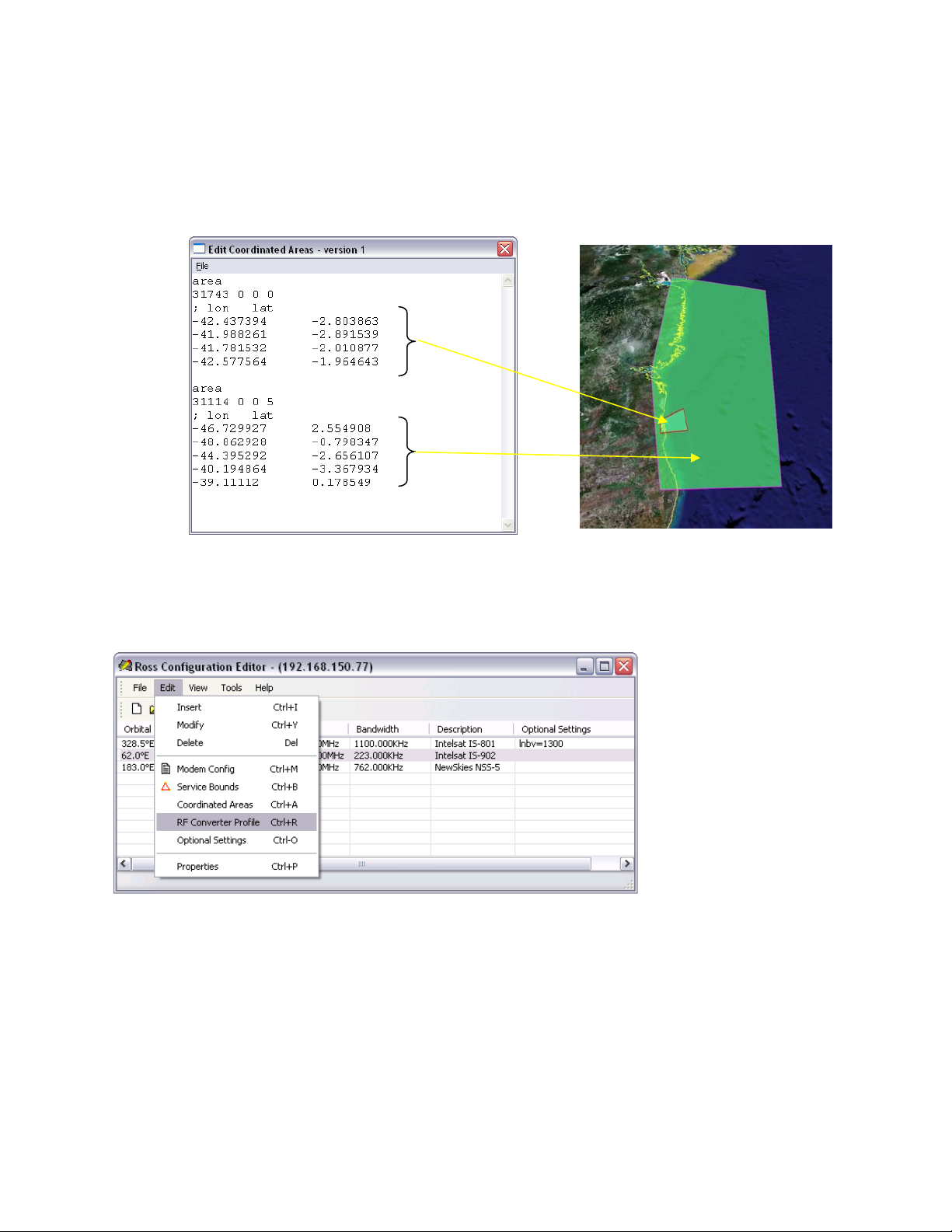
ROSS MN/13070
Figure 10 shows the Coordinated Area Editor with coordinated areas in the proper sequence,
where the contained polygon is declared before the containing polygon. This order ensures that
area 31743 is always tested before area 31114. If area 31114 were declared first, area 31743 will
not be visible for position testing.
Figure 10: Coordinated Areas Order Declaration
5.18 Edit RF Converter Profile
This feature is intended to be used primarily with ACUs that support multiband LNBs. By using
the optional setting (see Optional Settings), the ACU can be configured to select a specific
frequency band in the LNB down converter. The RF Converter Profile dynamically updates the
down converter settings in VMS to match those of the actual LNB on the vessel. This ensures
that VMS performs correct frequency calculations in the event that the antenna subsystem has
switched multiple Local Oscillator bands, typically Ku-Band operations.
Comtech EF Data, Vipersat Products Page 63 of 87
Page 64

ROSS MN/13070
In the same manner, the up converter profile can also be altered to adjust frequency allocation
restrictions. This is useful when the ROSS unit performs a handoff from one satellite operating in
one band to another satellite operating in another band or even within the same satellite.
Normally this up converter section should remain unchecked as it does require extreme
caution when adjusting transmitting parameters.
TDM Reference Power is NOT
required, future usage.
Normally remains unchecked
However, this may be useful if up conversion restrictions are required in specific service areas,
e.g. vessels entering port and limited frequency band operations are enforced. If these conditional
areas are required, the operator may configure custom up converter settings to force the system
to limit the frequency range and center on very specific region of the pooled bandwidth.
Enabling and modifying converter settings places stored values within the selected Service Area
entry. As the service area is invoked, the Frequency Converter Profile is sent to VMS in the last
stage of a satellite handoff during modem registration process (see section 3.3.2 step 8). The new
configuration replaces the settings in VMS’s database for the down converter or up converter
assigned to the roaming remote modem. As previously stated, the updated converter
configuration ensures that the frequency calculations performed by VMS are correct with respect
to the actual satellite operating band.
5.18.1 Multiband LNB Support
Under multiband LNB operations it is important that this down converter Local Oscillator
frequency value matches that of the antenna controller value set in Optional Setting, (see section,
6.1.18). If a different LO is selected (used) other than the base set in the VMS database for the
site, it will be necessary to alter this value per service area to match.
Comtech EF Data, Vipersat Products Page 64 of 87
Page 65

ROSS MN/13070
To properly set the corresponding LO frequency value, the network administrator will be
required to consult the antenna manufactures set voltage/tone tables to determine the correct LO
frequency. After determining the LO frequency, apply this frequency value to the Local
Oscillator field and enable the down converter as indicated below.
As previously mentioned the set values within the service area will be pushed to the VMS for
updating of the remote down/up converter conversions.
Down converter configuration for multiband
LNB control. Converter Type must also match
that of the shipboard equipment installed.
Refer to VMS Users Guide for additional information on configuring converter operations.
Comtech EF Data, Vipersat Products Page 65 of 87
Page 66

ROSS MN/13070
5.18.2 Edit Optional Settings
Global Satellite configurations differ in manufactured structure requiring receiving antenna
subsystems to modify their RF characteristics on the fly. The following unique Optional Settings
allow each SA to have a unique configuration for the receiving LNB to dynamically adapt to
different frequency bands and transponder polarities.
These receiver options assist in creating specific ACU settings providing additional controls for
global roaming between satellite configurations. The LNB band select is a combination of
Voltage and Tone settings that correspond to switched Local Oscillator frequency band.
The polarization setting can also provide either cross-polarization (X-Pol) or concurrent
polarization (Co-Pol) if the ACU supports this option.
After determining the correct settings to generate the proper configuration per satellite service
area, make sure that the LO frequency value is updated in the RF Converter Profile previously
described.
Consult the LNB and/or ACU vendor specific documentation for the settings needed to select a
specific LNB band and polarization.
Comtech EF Data, Vipersat Products Page 66 of 87
Page 67

ROSS MN/13070
5.19 Tools Download
The tools menu provides the uploading and downloading of generated ROSS service areas. In
addition the ROSS application is upgradable by locating the newer version and selecting upload
to send either locally over LAN connection or the air interface. The RCE handles all the stored
file information as part of the upload/download processing, transforming the binary information
to and from human text format.
Download will connect to the properties set IP address pulling the previously configured ROSS
service area information. This is useful for editing existing ROSS database information.
5.20 Tools Upload
The upload will push newly created or edited service area files to select ROSS IP Addresses.
After creation or downloaded editing, select upload to send modified data information.
Comtech EF Data, Vipersat Products Page 67 of 87
Page 68

ROSS MN/13070
5.21 Tools Download Event Log
The ROSS stores all system events log information on-board and either viewed through the client
interface or is downloadable for local storage and off-line viewing. When download event log is
selected the RCE will establish an IP connection to the ROSS unit coping and transforming the
system event log file to text format. During the download process a Windows file manager will
prompt the use to select a location for local disk storage.
Example of download event file format:
The saved text event log file is comma delimited for viewing and sorted content manipulation.
Comtech EF Data, Vipersat Products Page 68 of 87
Page 69
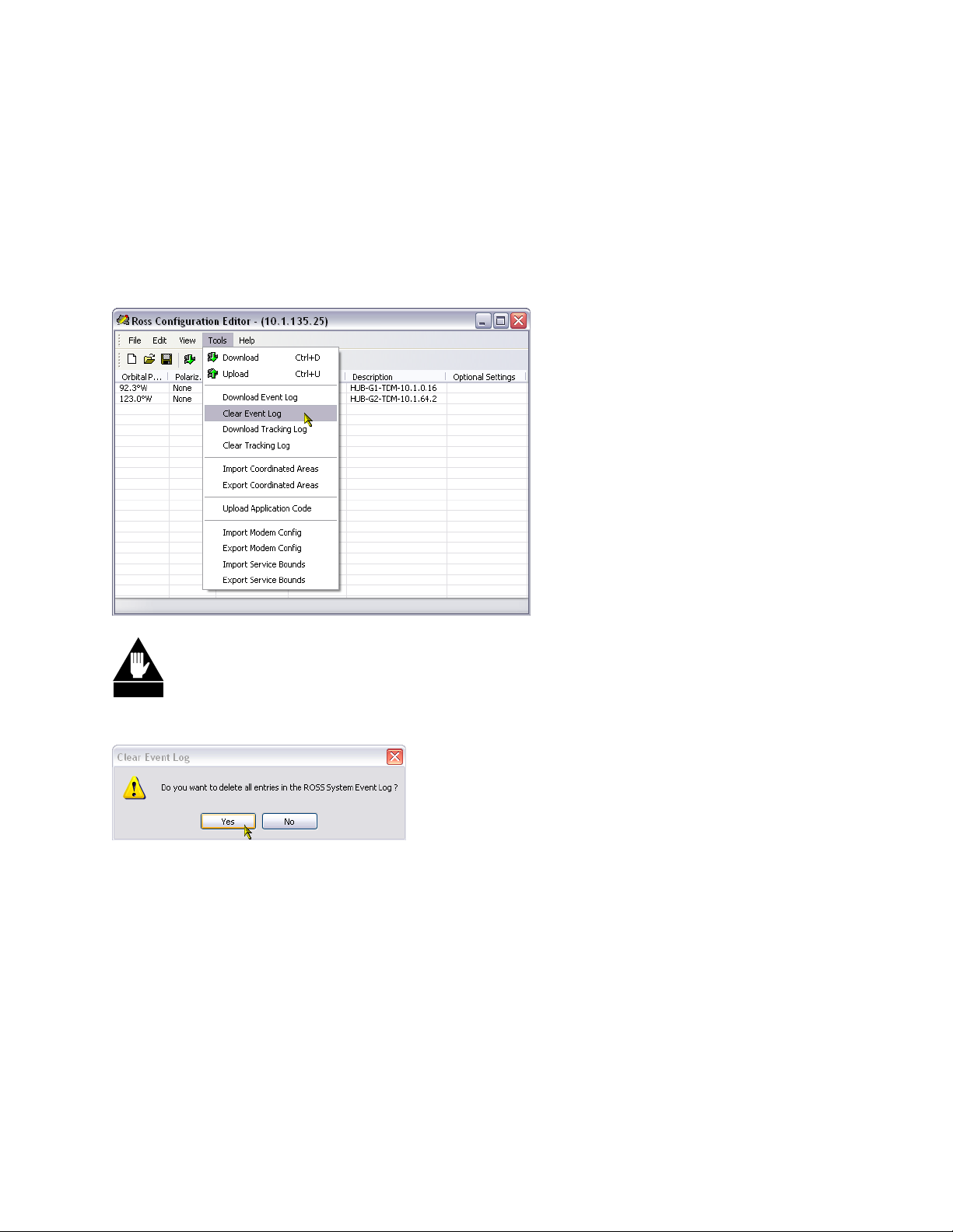
ROSS MN/13070
5.22 Tools Clear Event Log
The ROSS stores all system events logs locally in non-volatile memory. The log information is
viewed from Telnet Command Line Interface and provides the control to clear the stored events.
The ROSS editor also provides a tool to clear the stored events remotely. By selecting the Clear
Event Log the editor will send a command to the addressed ROSS unit clearing all stored system
events.
WARNING
aavvaaiillaabbllee ffoorr ddoowwnnllooaadd.. MMaakkee ssuurree tthhaatt yyoouu ddoowwnnllooaadd eevveennttss bbeeffoorree cclleeaarriinngg iiff nneecceessssaarryy!!
WWaarrnniinngg,, aafftteerr sseelleeccttiinngg tthhiiss ccoommmmaanndd tthhee eevveennttss ffoorr tthhee sseelleecctteedd sseerrvveerr wwiillll nnoo lloonnggeerr bbee
5.23 Tools Download Tracking Log
The ROSS stores all system tracking log information on-board and either viewed through the
client interface or is downloadable for local storage and off-line viewing. When download
tracking log is selected the RCE will establish an IP connection to the ROSS unit coping and
transforming the system tracking log file to text format. During the download process a
Windows file manager will prompt the use to select a location for local disk storage.
Comtech EF Data, Vipersat Products Page 69 of 87
Page 70

ROSS MN/13070
Example of download tracking file format:
The saved text tracking log file is comma delimited for viewing and sorted content manipulation.
5.24 Clear Tracking Log
The ROSS stores all system tracking logs locally every 20 minutes in non-volatile memory. The
log information is viewed from Telnet Command Line Interface and provides controls to only
view the stored events. The ROSS editor provides a method to clear the stored tracking events
remotely. By selecting the Clear Tracking Log the editor will send a command to the addressed
ROSS unit clearing all stored tracking events.
Comtech EF Data, Vipersat Products Page 70 of 87
Page 71
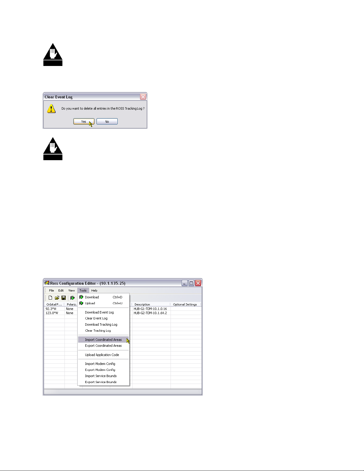
ROSS MN/13070
WARNING
AAfftteerr sseelleeccttiinngg tthhiiss ccoommmmaanndd tthhee ttrraacckkiinngg eevveennttss ffoorr tthhee sseelleecctteedd sseerrvveerr wwiillll nnoo lloonnggeerr bbee
aavvaaiillaabbllee ffoorr ddoowwnnllooaadd.. MMaakkee ssuurree tthhaatt yyoouu ddoowwnnllooaadd ttrraacckkiinngg eevveennttss bbeeffoorree cclleeaarriinngg iiff
nneecceessssaarryy!!
WARNING
bbeeffoorree uuppddaattiinngg RROOSSSS aapppplliiccaattiioonn.. TThheerree wwaass uunnaavvooiiddaabbllee rreessttrruuccttuurriinngg ooff t
BBeeffoorree uuppggrraaddiinngg ttoo RROOSSSS vveerrssiioonn 11..33..00..992211,, ddoowwnnllooaadd aanndd ssttoorree TTrraacckkiinngg LLoogg ffii
t
hhee ttrraacckkiinngg lloogg
ddaattaabbaassee iinn oorrddeerr ttoo eennhhaannccee ddoowwnnllooaadd ppeerrffoorrmmaannccee.. LLooaaddiinngg tthhiiss llaatteesstt vveerrssiioonn ooff RROOSSSS
llee
ssooffttwwaarree wwiillll ccoorrrruupptt eexxiissttiinngg hhiissttoorryy ffiillee,, rreessuullttiinngg iinn lloosstt iinnffoorrmmaattiioonn.. AAnnyy nneeww vveerrssiioonnss wwiillll nnoott
rreeqquuiirree tthhiiss pprroocceessss..
5.25 Import & Export of Coordinated Area Maps
If it becomes necessary to generate hundreds of CAM’s within a network in maybe useful to
copy the same CAM information to all or a select few ROSS units as most will probably operate
within the same region with the same configuration. The RCE provides the ability to import and
export coordinated areas by selecting the SA from the list for import. With this ability it also
possible to uniquely copy & paste only selected SA’s within a group.
This same import/export commands are also available for service bounds and modem
configuration files.
Comtech EF Data, Vipersat Products Page 71 of 87
Page 72

ROSS MN/13070
5.26 Uploading Application Code
Selecting the Upload Application Code from the Tools menu allows a new image of ROSS
system firmware to be uploaded to a ROSS unit. This command will call the Windows file
manager prompting the user to locate the image (SW13069D.app) from saved location. After
selection the RCE with send the file over a TCP connection using the set RCE IP address.
After the application code (.app file) has been transferred it will be checked for integrity. If the
integrity check passes, the ROSS will perform a soft reboot which loads and executes the new
application code.
Comtech EF Data, Vipersat Products Page 72 of 87
Page 73

ROSS MN/13070
6 Retrieving Event and Tracking Logs
Description
GetLog is a windows console application that retrieves events stored in the ROSS event log and
tracking log. GetLog can be run directly from the command line console or as a scheduled task
using the windows task scheduler.
Installation
Copy the ‘GetLog.exe’ into a directory where the user has valid write and execute privileges.
This application can be installed on a VMS Client PC. Only users with privileges should run this
application.
Operation
GetLog can be executed in two modes: (1) console, (2) scheduled task. Before using GetLog in
any mode, it is highly recommended that connection status to ROSS is verified active.
Command Options
The GetLog console application has the following command line options:
-e downloads the entire System Event Log file.
No option downloads the entire Tracking Log file.
For example, the following command retrieves all event logs. The output is saved as application
generated log.txt file and written into the path from where GetLog was executed.
GetLog –e destination (where destination is the IP Address of desired ROSS unit)
To retrieve tracking logs it is recommend that a separate copy of GetLog application is executed
from a different directory as the output file name is generate with the same naming convention
“log.txt”.
GetLog “no options” destination
Note each time GetLog is executed it will overwrite the existing file, recommend renaming or
setting up system date environment variables to preserve each downloaded copy. Batch files will
help to schedule multiple lists of ROSS units.
Scheduled Task Mode
Comtech EF Data, Vipersat Products Page 73 of 87
Page 74

ROSS MN/13070
The ROSS log retrieval process can be automated by using the Windows Task Scheduler. The
Windows Task Scheduler will execute GETLOG on a scheduled basis. To create a scheduled
GetLog task, use the Scheduled Task Wizard. Follow the steps below:
a. Open the Windows Task Scheduler by clicking Start, click All Programs, point to
Accessories, point to System Tools, and then click Scheduled Tasks.
b. Click on the Add Scheduled Task item. This will open the “Scheduled Task
Wizard”
c. When prompted to select the “Windows program to run”, click on Browse, and
select the GetLog.exe from its install directory.
Destination IP address of desired
ROSS unit or add ‘e’ option for
event log
b. Select a name for the task and scheduled period (Daily, Weekly, Monthly, etc…).
c. Set the start time, start date, and recurrence options.
d. Enter your user and name password to confirm the new task entry. This username
and password should be a valid VMS user. g) In the last step, check the “Open
advanced properties for this task ….” Option, then click Finish.
e. The last step is to add the GetLog command options to the task. In the Run text
box, go to the end of the GetLog.exe and add the desired options. The GetLog
application will be run as a scheduled task by the Windows Task Scheduler.
An alternative method to running a scheduled GetLog task is to create a batch file that calls
GetLog with the desired options. A scheduled task is created to run this batch file. This
simplifies the maintenance as only the batch file needs to be modified if they are any changes to
GetLog options.
Other alternatives would be to create a small script that would run in the background calling a
list of destination on scheduled bases.
Comtech EF Data, Vipersat Products Page 74 of 87
Page 75

ROSS MN/13070
Appendix A: Documents and Glossary
APPLICABLE DOCUMENTS
ii. 0806-SOTM Global Vessel Satellite Roaming – Rev3
iii. ROSS Functional Specifications – ROSS-FPSEC-J
iv. ROAM Protocol ICD_R1.5
v. VMS Users Guide, MN-22156_r6_VMS
vi. CDM-570/570L Installation Operational Manual, Doc MN/CDM570L.IOM, Rev5
vii. Vipersat CDM-570/570L Users Guide, Doc 22125, Rev2, FW Ver.1.5.4
viii. Vload Users Guide, Doc 22117, Rev1.0, SW Ver. 3.5.x
ix. Sea Tel Installation and Operation Manual, DAC-2202, Doc 122933-A
x. Orbit Marine Installation Operation , AL-71xx, Doc MAN26-1327
GLOSSARY
ACU – Antenna Control Unit
ASR – Automatic Switch Request
CAM – Coordinated Area Map
CDM – Comtech Data Modem
DPC – Dynamic Power Control
dSCPC – Dynamic Single Channel Per Carrier
ECM – Entry Channel Mode
ESV – Earth Station on-board Vessel
PCU – Pedestal Control Unit
RCE - ROSS Configure Editor
ROSS – Roaming Oceanic Satellite Server
SB – Service Boundary
SA – Service Area
SCPC – Single Channel Per Circuit
SLIP – Satellite Location Identification Protocol
SOTM – Satellite On The Move
STDMA – Selective Time Division Multiple Access
TEK – Transmit Enable Keep-alive
VMS – Vipersat Management System
Comtech EF Data, Vipersat Products Page 75 of 87
Page 76

ROSS MN/13070
Appendix B: Sea Tel DAC-2202
ROSS ACU Configuration
For the Sea Tel ACU, the configuration options are port type, IP address, and port number. At
this time, the port type is “tcp” and the default port is 2000. For example, using the ACU
Configuration value of “tcp 192.168.150.45 2000” configures ROSS to communicate with
the Sea Tel ACU using a TCP connection to port 2000 (decimal) on an ACU at IP address
192.168.150.45.
Optionally, after the TCP connection port number a message timeout value and message
validation is configurable. The timeout values are in milliseconds, e.g. 5000, 5 seconds. The
internal default timeout is 2 seconds and if determined necessary because of bad (unresolved)
LAN communications, this additional wait time may help. If problems like this persist, correct
hardware issues.
Message validation is by default whereby all command message sent to the ACU are queried and
compared. If any of the sent commands return as mismatched the ROSS process will attempt up
to three retries, if all attempts fail ROSS will report a service handoff failure. If validations are
failing because of known mismatch incompatibilities, this check can be disabled by appending
the ACU Configuration with pipe ( | ) character followed by “novalidate”.
Comtech EF Data, Vipersat Products Page 76 of 87
Page 77

ROSS MN/13070
Comtech EF Data CDM-570L, Sea Tel DAC-2202, and ROSS Hardwire Interconnect
Wiring:
The CDM570L is connected to the DAC 2202 ACU through the Terminal Mounting Strip (TMS)
using the Comtech Modem Interface cable assembly 126877-B. The cable assembly is designed
to work with older and newer versions of the TMS, however when using the newer version of the
TMS the +12/24V pull-up connection is not required as there is a voltage pull-up jumper instead.
When using the newer terminal PCBA with pull-up jumper, clip the +12/24V line from cable
assembly. See Comtech Modem Interface Cable Assembly, Figure 12.
SEATEL ACU
110/220 VAC
LAN 10/100BaseT
M&C
Ship GyroNEMA
EXT AGC
GND
SW2
Antenna
Interconnect
L-Band Receive
110/220 VAC
110/220 VAC
L-Band Transmit
LAN 10/100BaseT
LAN 10/100BaseT
Alarm
TXRX
CDM-570L
2
1
ROSS
Ethernet Switch
B
7
-
8
7
6
Figure 11, ROSS to Sea Tel DAC-2202 to CDM-570L Interconnect Diagram
+12/24V
Comtech EF Data, Vipersat Products Page 77 of 87
Page 78

ROSS MN/13070
SEATEL ACU
110/220 VAC
LAN 10/100BaseT
M&C
Ship GyroNEMA
EXT AGC
GND
SW2
Antenna
Interconnect
L-Band Receive
L-Band Transmit
TX RX
SLM-5650A
110/220 VAC
LAN 10/100BaseT
Auxiliary
(J9)
l
e
a
b
C
w
N
e
ROSS
110/220 VAC
LAN 10/100BaseT
Ethernet Switch
Figure 12, ROSS to Sea Tel DAC-2202 to SLM-5650A Interconnect Diagram
Comtech EF Data, Vipersat Products Page 78 of 87
Page 79

ROSS MN/13070
ROSS to ACU Hardware Controls Signals
The Sea Tel DAC-2202 supports blocked, pointing error and RF radiation hazard carrier muting
signaling function on a 25 pin terminal mounting strip (TB2). Also modem lock input for
positive satellite ID. (See Sea Tel document DAC-2202 ACU for more details).
To comply with FCC CFR part 25.222(a6)(a7), cease carrier transmission through pointing error
or blockage, this hardware level (TTL) interface is connected to the ROSS unit through hardwire
connections. The ACU shorts pin SW2 to GND (on TB2-Terminal Mounting Strip) when
antenna is outside the configured pointing limit of 0.5 degree from satellite peak or limit stop
blockage occurred, thus muting modulator carrier output.
CDM-570 Satellite Signal Identifier Connection
The modem rear panel RX Traffic Alarm indicator connector pin 15 (RX-NC, Locked) is pulled
low (grounded) by the modem when demodulator lock is detected, this is used as a positive ID to
the antenna controller to stop tracking and peak on signal. When RX Traffic is faulted, (RX-NO,
Unlocked) the signal to the ACU (EXT AGC, TB2) is pulled high indicating demodulator
unlocked condition, within ~20 seconds the ACU will commence retargeting of the antenna.
SLM-5650A Satellite Signal Identifier Connection
The modem rear panel Auxiliary connector J9-HD-15F (Rx TTL Fault) is logic Low when not
faulted indicating demodulator lock, this is used as a positive ID to the antenna controller to stop
tracking and peak on signal. When RX is faulted, the signal to the ACU (EXT AGC, TB2) is
pulled high indicating demodulator unlocked condition, within ~20 seconds the ACU will
commence retargeting of the antenna.
External AGC input must be 0 to 5 Volts DC analog signal, positive going voltage
proportional to satellite signal input level and must be real-time in its response to antenna
pointing.
External Modem Lock from a satellite modem is used as a positive ID that the antenna is
on the desired satellite. This input is NOT used for tracking purposes; it is only used for
satellite identification to acquire the correct satellite during search. To enable the external
modem input you must the ACU SYSTEM TYPE parameter to 79 and NID MUST be set
to 0000 indicating no DVB NID used.
o Lock Logic - The modem lock signal connects to EXT AGC and a ground
reference from the modem connects to GND. The expected signal from the
modem is 0VDC to +5VDC. Low voltage indicates modem lock, high voltage
indicates modem unlock.
Comtech EF Data, Vipersat Products Page 79 of 87
Page 80

ROSS MN/13070
ACU SYSTEM TYPE:
This determines the system options according to the following table. Add together all the desired
options to determine the proper entry. These are typical settings and users should refer to your
antenna manual.
128 Reverse External Modem Lock input polarity (logic hi = lock)
64* Enables LNB voltage output
32 Display Relative in the Azimuth entry display
16 Reverse blockage output logic (SW2 logic hi = blocked)
8* Enable AFC in NBIF Mode
4* Auto SAT load after SEARCH failure
2* Enable External Modem Lock Input (logic low = lock)
1* Auto SAT load on “hot” RESET and ACU Power-Up
79*
Figure 12, Comtech 570 Modem Interface Cable Assembly
Comtech EF Data, Vipersat Products Page 80 of 87
Page 81

ROSS MN/13070
Figure 12, Comtech 5650A Modem Interface Cable Assembly
Comtech EF Data, Vipersat Products Page 81 of 87
Page 82

ROSS MN/13070
Appendix C: Orbit Technologies OrSat AL-7200 Controller
For the Orbit Technologies Group Orsat AL-7100 series controller, enter “al-7x” in the ACU
Type field. The ACU Configuration field consists of the interface type, IP address, and port
number. At this time, the port type is “tcp” and the default port is 5002. For example, using the
ACU Configuration value of “tcp 192.168.150.45 5002” (no quotes) configures ROSS to
communicate with the Orbit SBC using a TCP connection to port 5002 (decimal) on an SBC at
IP address 192.168.150.45.
Note that the Orbit documentation uses that term “SBC” (single board computer) instead of ACU.
The term “CCU” (central control unit) refers to the Orbit local console interface for the SBC.
Optionally, after the TCP connection port number a message timeout value can be set. The
timeout values are in milliseconds, e.g. 5000, 5 seconds. The internal default timeout is 2
seconds and if determined necessary because of bad (unresolved) LAN communications, this
additional wait time may help. If problems like this persist, correct hardware issues.
Service Area Parameters
When ROSS is used with the Orbit AL-71xx antenna system, the Service Area parameters
Polarization, Frequency, and Bandwidth are interpreted as the receiver settings.
The Orbit controller also supports two “Optional Settings” parameters. The values “lnbv13” and
“lnbv17” specify two voltage levels (13V & 17V respectively) that are sent to LNB during a
satellite handoff. This parameter is typically used for dual-band LNB.
Comtech EF Data, Vipersat Products Page 82 of 87
Page 83

ROSS MN/13070
Comtech EF Data/Orbit Hardware Control Wiring:
The cable assembly in figure 13 below interconnects the hardware control lines between the
Orbit OrSat AL-71xx. Consult the Orbit documentation for more detailed information about the
installation and configuration of the Orbit antenna system.
Figure 13, Modem to CCU Cable Connection
Comtech EF Data, Vipersat Products Page 83 of 87
Page 84

ROSS MN/13070
Appendix D: ROAM Protocol
The ROAM protocol is simple, efficient, and flexible open standard. The protocol messages are
limited to a minimum control set required by ROSS to perform satellite handoffs and monitor
status.
ROSS ACU Configuration
For the roam ACU type, the configuration options are port, IP address, and port number. The
port type is “udp” and the default port is 49184. For example, using the ACU Configuration
value of “udp 172.18.140.50 49184” configures ROSS to communicate with any ACU
equipped with the ROAM protocol.
CDM-570 Satellite Signal Identifier Connection
The modem rear panel RX Traffic Alarm indicator connector pin 15 (RX-NC, Locked) is pulled
low (grounded) by the modem when demodulator lock is detected, this is used as a positive ID to
the antenna controller to stop tracking and peak on signal. When RX Traffic is faulted, (RX-NO,
Unlocked) the signal to the ACU is open and may require a logic pull-up to signal a high
indicating demodulator unlocked condition.
SLM-5650A Satellite Signal Identifier Connection
The modem rear panel Auxiliary connector J9-HD-15F (Rx TTL Fault) is logic Low when not
faulted indicating demodulator lock, this is used as a positive ID to the antenna controller to stop
tracking and peak on signal. When RX is faulted, the signal to the ACU is open and may require
a logic pull-up to signal a pulled high indicating demodulator unlocked condition.
Note interconnect wiring will vary depending on ACU equipment.
For more information on ROAM protocol refer to “ROAM Protocol ICD_R1.5” document.
Comtech EF Data, Vipersat Products Page 84 of 87
Page 85

ROSS MN/13070
Appendix E: LAN Configuration SetIP
LAN configuration utility (LAN CFG – SetIP) provides a unique Ethernet messaging exchange
to remotely configure unknown or default ROSS IP addresses. This small Windows application
broadcasts a proprietary packet which all ROSS unit’s listen for and respond with MAC, IP and
version information. This simplifies and eliminates need to modify the IP address of the PC
especially if the ROSS units IP address is known.
New Installations and Modifications
The SetIP application sends a broadcast message to any listening ROSS unit(s) on the same LAN
segment. The message being a broadcast IP packet will not pass through LAN devices that block
broadcasts, e.g. smart switches, routers, etc. Typically if the local LAN switch is configured to
allow broadcasts to pass all ports this program will reach any connected ROSS unit.
If the network devices present a problem, the PC running SetIP can be directly connected using a
standard CAT5 cable.
The application is easy to use, by selecting the Scan button a single message is sent waiting for
any active ROSS unit to respond.
Once a unit receives the message they respond back to the sender with the following information,
MAC address of the device, current IP address and software version.
Comtech EF Data, Vipersat Products Page 85 of 87
Page 86

ROSS MN/13070
Select the desired unit from the list and click Set IP.
Configure the new IP address, Subnet mask and default gateway, click OK. The program will
send the changes to the selected ROSS. The ROSS unit upon reception will update the address
but not store the address to flash (persistent memory).
NNoottee iitt wwiillll bbee nneecceessssaarryy ttoo ccoonnnneecctt ttoo tthhee uunniitt aanndd ssaavvee ttoo ffllaasshh mmeemmoorryy.. UUssiinngg PPuuttttyy,, tteellnneett ttoo
tthhee uunniitt sseelleecctt ““SSaavvee”” uunnddeerr tthhee ccoonnffiigguurraattiioonn mmeennuu ttoo mmaakkee tthhee nneeww aaddddrreessss ppeerrssiisstteenntt..
You can repeat this process for each of the units listed; however use caution when identifying
which unit is which if more than one is listed.
Comtech EF Data, Vipersat Products Page 86 of 87
Page 87

ROSS MN/13070
2114 WEST 7TH STREET TEMPE ARIZONA 85281 USA
480 • 333 • 2200 PHONE
480
• 333 • 2161 FAX
Comtech EF Data, Vipersat Products Page 87 of 87
 Loading...