

Page 1

RCU108
1:8 Converter Protection Switch
Installation and Operation Manual
TM066 - Rev. 1
April, 1997
- NOTICE -
1997, Radyne Corporation. All rights reserved.
Unauthorized reproduction of this manual in any form
without the expressed written approval of Radyne
Corporation is strictly prohibited. This manual may not
in whole or in part be copied, reproduced, translated or
reduced to any electronic or magnetic storage medium
without the written consent of a duly authorized officer
of Radyne Corporation.
Radyne Corporation • 5225 South 37th St. • Phoenix, AZ 85040 • (602) 437-9620 • Fax: (602) 437-4811
Page 2

Page 3

RCU108 1:8 Protection Switch Warranty Policy
RADYNE WARRANTY POLICY
WARRANTY AND SERVICE
Radyne (Seller) warrants the items manufactured and sold by Radyne to be free of defects in material and
workmanship for a period of two (2) years from date of shipment Radyne's obligation under its warranty is
limited in accordance with the periods of time and all other conditions stated in all provisions of this
warranty.
This warranty applies only to defects in material and workmanship in products manufactured by Radyne.
Radyne makes no warranty whatsoever concerning products or accessories not of its manufacture.
Repair, or at Radyne's option, replacement of the Radyne products or defective parts therein shall be the
sole and exclusive remedy for all valid warranty claims.
WARRANTY PERIOD
The applicable warranty period shall commence on the date of shipment from Radyne's facility to the
original purchaser and extend for the stated period following the date of shipment. Upon beginning of the
applicable Radyne warranty period, all customer's remedies shall be governed by the terms stated or
referenced in this warranty. In-warranty repaired or replacement products or parts are warranted only for
the remaining unexpired portion of the original warranty period applicable to the repaired or replaced
products or parts. Repair or replacement of products or parts under warranty does not extend the original
warranty period.
WARRANTY COVERAGE LIMITATIONS
The following are expressly not covered under warranty:
1. Any loss, damage and/or malfunction relating in any way to shipping, storage, accident, abuse,
alteration, misuse, neglect, failure to use products under normal operating conditions, failure to use
products according to any operating instructions provided by Radyne, lack of routine care and
maintenance as indicated in any operating maintenance instructions, or failure to use or take any proper
precautions under the circumstances.
2. Products, items, parts, accessories, subassemblies, or components which are expendable in normal
use or are of limited life, such as but not limited to, bulbs, fuses, lamps, glassware, etc.
3. Radyne reserves the right to revise the foregoing list of what is covered under this warranty.
WARRANTY REPLACEMENT AND ADJUSTMENT
Radyne will not make warranty adjustments for failures of products or parts which occur after the specified
maximum adjustment period. Unless otherwise agreed, failure shall be deemed to have occurred no
more than seven (7) working days before the first date on which a notice of failure is received by Radyne.
Under no circumstances shall any warranty exceed the period stated above unless expressly agreed to in
writing by Radyne.
LIABILITY LIMITATIONS
This warranty is expressly in lieu of and excludes all other express and implied warranties, including but
not limited to warranties of merchantability and of fitness for particular purpose, use, or applications, and
all other obligations or liabilities on the part of Radyne, unless such other warranties, obligations, or
liabilities are expressly agreed to in writing by Radyne.
All obligations of Radyne under this warranty shall cease in the event its products or parts thereof have
been subjected to accident, abuse, alteration, misuse or neglect, or which have not been operated and
maintained in accordance with proper operating instructions.
In no event shall Radyne be liable for incidental, consequential, special or resulting loss or damage of any
kind howsoever caused. Radyne’s liability for damages shall not exceed the payment, if any, received by
TM066 - Rev. 1 ii
Page 4

Warranty Policy RCU108 1:8 Protection Switch
Radyne for the unit or product or service furnished or to be furnished, as the case may be, which is the
subject of claim or dispute.
Statements made by any person, including representatives of Radyne, which are inconsistent or in conflict
with the terms of this warranty, shall not be binding upon Radyne unless reduced to writing and approved
by an officer of Radyne.
WARRANTY REPAIR RETURN PROCEDURE
Before a warranty repair can be accomplished, a Repair Authorization must be received. It is at this time
that Radyne will authorize the product or part be returned to the Radyne facility or if field repair will be
accomplished. The Repair Authorization may be requested in writing or by calling:
RADYNE CORPORATION
5225 South 37th Street
Phoenix, Arizona 85040 (USA)
ATTN: Customer Support
Phone: (602) 437-9620 Fax: (602) 437-4811
Any product returned to Radyne for examination must be sent prepaid via the means of transportation
indicated as acceptable to Radyne. Return Authorization Number must be clearly marked on the shipping
label. Returned products or parts should be carefully packaged in the original container, if possible, and
unless otherwise indicated, shipped to the above address.
NON-WARRANTY REPAIR
When a product is returned for any reason, Customer and its shipping agency shall be responsible for all
damage resulting from improper packing and handling, and for loss in transit, not withstanding any defect
or nonconformity in the product. By returning a product, the owner grants Radyne permission to open and
disassemble the product as required for evaluation. In all cases, Radyne has sole responsibility for
determining the cause and nature of failure, and Radyne's determination with regard thereto shall be final.
TM066 - Rev. 1 iii
Page 5

Page 6

RCU108 1:8 Protection Switch Record of Revisions
RCU108 1:8 Protection Switch
Installation and Operation Manual
TM066 - Record of Revisions
Radyne Corporation is constantly improving its products and therefore the information in this document is
subject to change without prior notice. Radyne Corporation makes no warranty of any kind with regard to
this material, including but not limited to the implied warranties of merchantability and fitness for a
particular purpose. No responsibility for any errors or omissions that may pertain to the material herein is
assumed. Radyne Corporation makes no commitment to update nor to keep current the information
contained in this document. Radyne Corporation assumes no responsibility for use of any circuitry other
than the circuitry employed in Radyne Corporation’s systems and equipment.
Revision
Level
1 5-10-97 Initial Release
Date Reason for Change
TM066 - Rev. 1 iv
Page 7

RCU108 1:8 Protection Switch Table of Contents
Table of Contents
1.0 Introduction….…..………………………………………………………………………………… 1-1
2.0 Installation Requirements..…...…………………………………………………………………… 2-1
2.1 Unpacking..………..………………………………………………………………………………… 2-1
2.1.1 Removal and Assembly..………………………………………………………………………… 2-1
2.2 Mounting Considerations.…..……………………………………………………………………… 2-1
2.3 Cabling..……………………………………………………………………………………………… 2-1
2.4 Hardware Interface..………………………………………………………………………………… 2-4
2.4.1 Backup Switch Interface Connector…………………………………………………………… 2-4
2.4.2 Switch Fault/Status Connector (J6)…….……………………………………………………….. 2-5
2.4.3 Up/Downconverter Equipment RS485 Port....………………………………………………… 2-5
2.4.4 RCU108 RF and IF Interfaces……….…………………………………………………………… 2-6
2.4.5 Interfaces Common to the Converters………………………………………………………… 2-10
2.4.6 Operator Serial I/O.……………………………………………………………………………… 2-10
3.0 Operation (Definitions)…….………………………………………………………………………… 3-1
3.1 Controls and Indicators………..…………………………………………………………………… 3-1
3.2 Operation……………………………..….………………………………… …………………………3-1
3.3 Switch Menu…………………………………….…………………………………………………… 3-3
3.4 Troubleshooting and/or Replacing a Faulted Converter………………………………………… 3-3
3.5 Learn Menu…………………………………………………………………………………………… 3-3
3.6 Learn Status Menu…………………………………………………………………………………… 3-4
3.7 Switch Logic…………………………………………………………………………………………… 3-4
3.8 Troubleshooting and/or Replacing a Faulted Converter……………………………………… 3-5
4.0 Periodic Maintenance…………..…………………………………………………………………… 4-1
Appendix A - Technical Specifications….……………………………………………………………… A-1
TM066 - Rev. 1 v
Page 8

TM054 - Rev. 1
vi
Page 9
RCU108 1:8 Protection Switch Description
Section One - RCU108 1:8 Protection Switch Description
1.0 Introduction
The Radyne RCU108 1:N Redundancy Control Unit provides backup protection for any number
of online converters ranging from 2 through 8. The switch will operate with any Radyne
Frequency Up or Downconverter product without distinction. The RCU108 Switch features plugand-play simplicity of operation. Simply install the cables, tell the Backup to ‘Learn,’ and the
protection switching is activated without complicated programming. Monitoring of all the online
converters and the operation of the switch becomes the duty of the backup converter. Identical
firmware in all Radyne converter products enables any converter plugged into the backup slot of
the switch to assume the role of protection system controller.
As the system controller, the designated backup converter communicates with the online
converters via the equipment RS485 interface. As a result, the switch contains a minimal
amount of circuitry and is therefore very reliable. Control and monitoring of all the online
converters and the switch itself can be performed through the operator RS232/422/485 serial
interface. Once the backup converter is told to learn the primary converters, the backup will
monitor the frequency, gain and channel settings of the online converter by polling the primary
converters on a periodic basis. If any changes are made to the online settings, the backup
converters will notify the user via the front panel or through the RS232/485 port. In the event
of a failure of any online converter, the restored circuit will have the same online settings that
were identified through the last learning process.
Menu programmable features in the backup converter allow various levels of backup priority to
be set. A priority of 1 would be the highest level of protection, where a priority of zero or none
means the converter would be logically removed from backup protection by the switch.
Manual backup from the front panel push-buttons on the switch allow the operator to fully test
the circuitry and operation of the protection switch system exactly as if a fault had been issued
by the converter being manually backed-up. Manual mode allows a converter to be removed or
reinstalled into the system without the fear of interrupting the circuit that has been routed
through the backup converter.
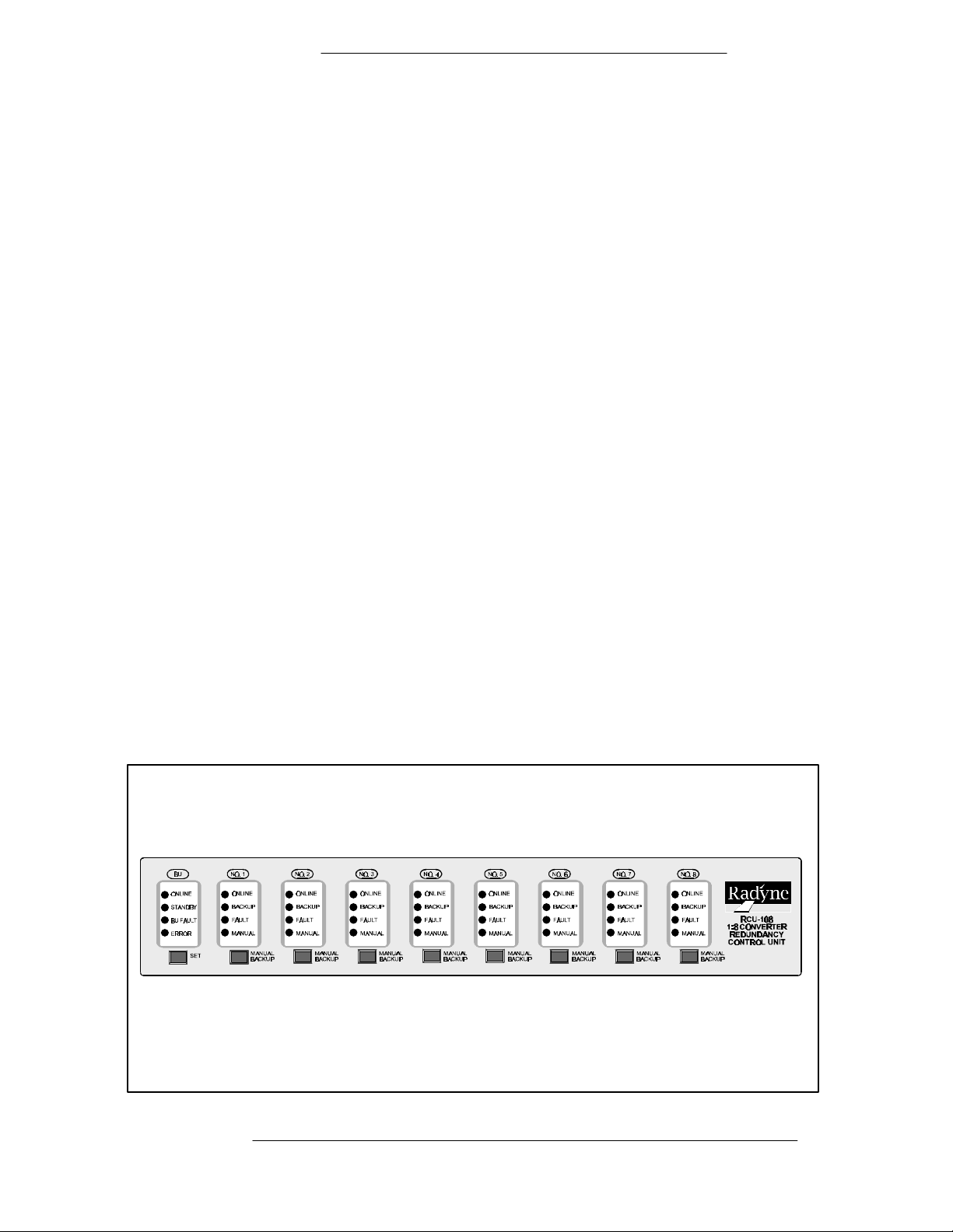
Figure 1-1. RCU108 1:8 Protection Switch Front Panel
TM066 - Rev. 1 Page 1-1
Page 10

Description RCU108 1:8 Protection
Switch
Page 1-2 TM054 - Rev. 1
Page 11

RCU108 1:8 Protection Switch Installation
Section 2 - Installation
2.0 Installation Requirements
The RCU108 is designed to be installed within any standard 19-inch equipment cabinet or rack,
and requires 2 rack units of mounting space (3.5 inches) vertically, and 17-inches of depth.
Including cabling, a minimum of 20-inches of rack depth is required. The unit can be placed on
a table or suitable surface if required.
⇒⇒ WARNING: There are no user-serviceable parts or configuration settings located
inside the RCU108 chassis. There is a potential shock hazard internally at the power
supply module. DO NOT open the RCU108 chassis under any circumstances.
⇒⇒ CAUTION: Before initially applying power to the unit, it is a good idea to disconnect
the transmit output from the operating satellite ground station equipment. This is
especially true if the current RCU108 configuration settings are unknown, where incorrect
setting could disrupt existing communications traffic.
2.1 Unpacking
The RCU108 was carefully packaged to avoid damage and should arrive complete with the
following items for proper installation:
1. RCU108 Unit.
2. One cable set per paragraph 2.3.
3. Installation and Operation Manual.
2.1.1 Removal and Assembly
If using a knife or cutting blade to open the carton, exercise caution to ensure that the blade does
not extend into the carton, but only cuts the tape holding the carton closed. Carefully unpack the
unit and ensure that all of the above items are in the carton.
The RCU108 is shipped fully-assembled and does not require removal of the covers for any
purpose in installation.
2.2 Mounting Considerations
When mounted in an equipment rack, adequate ventilation must be provided. The ambient
temperature in the rack should be between 10° and 35° C, and held constant for best equipment
operation. The air available to the rack should be clean and relatively dry.
2.3 Cabling
The RCU108 comes complete with all the cabling required to interface with the Upconverters or
Downconverters. Refer to Figure 2-1 to become familiar with the rear panel connectors on the
RCU108. Figure 2-2 shows a typical interconnection between four Upconverters and the
RCU108. The list of supplied cables is as follows:
P/N Description QTY
CA/3563 RS485 Equipment Interface Cable 1 for N (8 max.)
CA/4013-2 B/U Switch Interface Cabne 1 for N (8 max.)
TM066 - Rev. 1 Page 2-1
Page 12

Installation RCU108 1:8 Protection Switch
Page 2-2 TM066 - Rev. 1
Page 13

RCU108 1:8 Protection Switch Installation
TM066 - Rev. 1
Page 2-3
Page 14

Installation RCU108 1:8 Protection Switch
CA/3602-1 RF Cable Converter #1 1 Ea.
CA/3602-2 RF Cable Converter #2 1 Ea.
CA/3602-3 RF Cable Converter #3 1 Ea.
CA/3602-4 RF Cable Converter #4 1 Ea.
CA/3602-5 RF Cable Converter #5 1 Ea.
CA/3602-6 RF Cable Converter #6 1 Ea.
CA/3602-7 RF Cable Converter #7 1 Ea.
CA/3602-8 RF Cable Converter #8 1 Ea.
CA/3602-U RF Cable Backup Converter 1 Ea.
Routing of the cables between the converters and the switch is depicted in Figure 2-2. Note that
the RF/IF cabling included with the switch does not include cables to other panels in the rack.
2.4 Hardware Interfaces
Hardware interfaces between the online and backup converters and the switch equipment
include the RF interface, IF interface, Switch Interface, and Equipment RS-485 interface. In
addition to the above, the operator has access to all converter equipment in the system including
the switch via the operator RS-232 interface on the converter.
2.4.1 Backup Switch Interface (Converter Interface) Connector (J16 - J24)
The protection switch interface connector is a DB 15-pin connector that connects each converter
with the redundancy control unit. This cable serves as a direct link for each converter in the
configuration whether they are the primary converter or the backup unit. The pinout of the switch
is as follows:
Note: The DB 15-pin connector is identified as J5 on the converters and connects to the
Redundancy Control Unit J16 through J24. J16 connects to the backup converter, J17 connects
to converter #1, J18 connects to converter #2, J19 connects to converter #3, etc.
J16 - J24 B/U Switch Interface
Pin# DB 15 Nomenclature Description
1 N.O Form-C contact summary fault normally open contact
5 N.C. Form-C contact summary fault normally closed contact
9 COM Form-C contact summary fault common contact
13 GND
2 +15V Or’d Diode Or’d +15 Vdc from converter
6 FCB1 Fault Code bit 1
10 FCB2 Fault Code bit 2
14 FCB3 Fault Code bit 3
3 FCB4 Fault Code bit 4
7 IDB1 ID Bit 1
11 IDB2 ID Bit 2
15 IDB3 ID Bit 3
Page 2-4 TM066 - Rev. 1
Page 15

RCU108 1:8 Protection Switch Installation
4 IDB4 ID Bit 4
8 INT O Interrupt
12 RMT
The ID Bits provide information to the converter that tells the converter which slot (either primary
or backup) the converter is plugged into. The addresses are as follows:
IDB4 IDB3 IDB2 IDB1 Position
1 0 0 1 Backup
X X X X Primary Where: XXXX = 1 through 8 and
also identifies the slot to which the primary is
connected.
2.4.2 Switch Fault/Status Connector (J6)
The RCU108 Redundancy Control Unit contains a summary Fault/Status connector that is
available to the equipment operator for the purpose of monitoring the summary fault status of all
converters. The pinouts of this 15-pin D Sub connector are as follows:
J2 D sub 15 J6 D sub 15 Description
1 1 Converter Summary Status N.O.
2 9 Converter Summary Status Common
3 2 Primary/Backup Summary Fault Relay Common
4 10 Backup Summary Fault Relay N.O.
5 3 Primary #2 Summary Fault Relay N.O.
6 11 Primary #4 Summary Fault Relay N.O.
7 4 Primary #6 Summary Fault Relay N.O.
8 12 Primary #8 Summary Fault Relay N.O.
9 5 Converter Summary Status N.C.
10 13 Ground
11 6 ACC (Do not apply Voltage)
12 14 Primary #1 Summary Fault Relay N.O.
13 7 Primary #3 Summary Fault Relay N.O.
14 15 Primary #5 Summary Fault Relay N.O.
15 8 Primary #7 Summary Fault Relay N.O.
16 N/C
2.4.3 Up/Downconverter Equipment RS485 Port (J1)
An equipment multi-drop, full-duplex, bi-directional RS485 Interface allows communication
between converters. Because the RS485 interface uses a master/slave (talker/listener)
configuration, the converter that is designated the backup converter will automatically be
established as the master. Under normal RS485 protocol, the master will poll a specific slave
by address and only then will the slave unit respond. The swapping of Transmit Data and
Receive Data is accomplished in the inter-converter cable (CA/3563) as the hardware interface
is identical for all converters.
TM066 - Rev. 1
Page 2-5
Page 16

Installation RCU108 1:8 Protection Switch
J6 DB 9-Pin Description
1 GND
2 SRCLK
3 No Connect
4 TX Not
5 TX
6 SRDAT
7 No Connect
8 RX Not
9 RX
The signals on pins 2 and 6 of the DB9 connector are the clock and data of the I-squared bus
which is an interface employed in the 1:8 (RCU108) protection systems only.
2.4.4 RCU108 RF and IF Interfaces
The RF and IF connectors located on the rear of the RCU108 has four sections designated ‘A’
through ‘D’. Each section allows for two converter assignments. The RF and IF connector
designations are identical from section to section. The various sections are only differentiated by
the letter designations. Refer to Figure 2-1 to locate the IF and RF connectors outlined in the
following paragraphs.
2.4.4.1 Rear Panel Section A, Converter Number 1
J2 - IF Converter
This BNC/Female connector is routed from the IF connector (J2) of the RCU108 to J2 of
primary converter number 1. The connection is made through the IF cable assembly
CA/3598 which is a supplied item.
J3 - IF In/Out
This BNC/Female connector is routed from the User IF connector of the RCU108 to the
User Interface.
J7 - RF In/Out
This SMA/Female connector is routed from the User RF connector of the RCU108 to the
User Interface.
J8 - RF Converter
This SMA/Female connector goes to the RF connector of the RCU108 to the Primary
Converter number 1 (J1). This connection is made through supplied RF cable assembly
CA/3602-1.
J12 - RF Backup IN/OUT
This SMA/Female connector goes to the RF connector of the RCU108 to the Backup
Converter (J1). This connection is made through the supplied RF cable assembly
CA/3602-B.
J13 - Converter Interconnect
Page 2-6 TM066 - Rev. 1
Page 17

RCU108 1:8 Protection Switch Installation
This SMA/Female connector goes to the RF connector of the RCU108 to the RF
connector (J14) of the RCU108. The connection is made with CA/3602-U, a supplied
item.
2.4.4.2 Rear Panel Section A, Converter Number 2
J4 - IF Converter
This BNC/Female connector is routed from the IF connector (J2) of the RCU108 to J2 of
primary converter number 2. The connection is made through the IF cable assembly
CA/3598 which is a supplied item.
J5 - IF In/Out
This BNC/Female connector is routed from the User IF connector of the RCU108 to the
User Interface.
J9 - RF In/Out
This SMA/Female connector is routed from the User RF connector of the RCU108 to the
User Interface.
J10 - RF Converter
This SMA/Female connector goes to the RF connector of the RCU108 to the Primary
Converter number 2 (J1). This connection is made through supplied RF cable assembly
CA/3602-2.
J15 - Converter Interconnect
This SMA/Female connector goes to the RF connector of the RCU108 to the RF
connector (J12) section B of the RCU108. The connection is made with RF cable
assembly CA/3602-U, a supplied item.
2.4.4.3 Rear Panel Section B, Converter Number 3
J2 - IF Converter
This BNC/Female connector is routed from the IF connector (J2) of the RCU108 to J2 of
primary converter number 3. The connection is made through the IF cable assembly
CA/3598 which is a supplied item.
J3 - IF In/Out
This BNC/Female connector is routed from the User IF connector of the RCU108 to the
User Interface.
J7 - RF In/Out
This SMA/Female connector is routed from the User RF connector of the RCU108 to the
User Interface.
J8 - RF Converter
This SMA/Female connector goes to the RF connector of the RCU108 to the Primary
Converter number 3 (J1). This connection is made through supplied RF cable assembly
CA/3602-3.
J13 - RF Backup Interface
This SMA/Female connector goes to the RF connector of the RCU108 to the RF
connector (J14) of the RCU108. This connection is made through the supplied RF cable
assembly CA/3602-U.
TM066 - Rev. 1
Page 2-7
Page 18

Installation RCU108 1:8 Protection Switch
2.4.4.4 Rear Panel Section B, Converter Number 4
J4 - IF Converter
This BNC/Female connector is routed from the IF connector (J2) of the RCU108 to J2 of
primary converter number 4. The connection is made through the IF cable assembly,
CA/3598, which is a supplied item.
J5 - IF In/Out
This BNC/Female connector is routed from the User IF connector of the RCU108 to the
User Interface.
J9 - RF In/Out
This SMA/Female connector is routed from the User RF connector of the RCU108 to the
User Interface.
J10 - RF Converter
This SMA/Female connector goes to the RF connector of the RCU108 to the Primary
Converter number 4 (J1). This connection is made through supplied RF cable assembly
CA/3602-4.
J15 - RF Backup Interface
This SMA/Female connector goes to the RF connector of the RCU108 to the RF
connector (J12) section C of the RCU108. The connection is made with RF cable
assembly CA/3602-U, a supplied item.
2.4.4.5 Rear Panel Section C, Converter Number 5
J2 - IF Converter
This BNC/Female connector is routed from the IF connector (J2) of the RCU108 to J2 of
primary converter number 5. The connection is made through the IF cable assembly
CA/3598 which is a supplied item.
J3 - IF In/Out
This BNC/Female connector is routed from the User IF connector of the RCU108 to the
User Interface.
J7 - RF In/Out
This SMA/Female connector is routed from the User RF connector of the RCU108 to the
User Interface.
J8 - RF Converter
This SMA/Female connector goes to the RF connector of the RCU108 to the Primary
Converter number 5 (J1). This connection is made through supplied RF cable assembly
CA/3602-5.
J13 - RF Backup Interface
Page 2-8 TM066 - Rev. 1
Page 19

RCU108 1:8 Protection Switch Installation
This SMA/Female connector goes to the RF connector of the RCU108 to the RF
connector (J12) section C of the RCU108. The connection is made with RF cable
assembly CA/3602-U, a supplied item.
2.4.4.6 Rear Panel Section C, Converter Number 6
J4 - IF Converter
This BNC/Female connector is routed from the IF connector (J2) of the RCU108 to J2 of
primary converter number 6. The connection is made through the IF cable assembly
CA/3598 which is a supplied item.
J5 - IF In/Out
This BNC/Female connector is routed from the User IF connector of the RCU108 to the
User Interface.
J9 - RF In/Out
This SMA/Female connector is routed from the User RF connector of the RCU108 to the
User Interface.
J10 - RF Converter
This SMA/Female connector goes to the RF connector of the RCU108 to the Primary
Converter number 6 (J1). This connection is made through supplied RF cable assembly
CA/3602-6.
J15 - RF Backup Interface
This SMA/Female connector goes to the RF connector of the RCU108 to the RF
connector (J14) section D of the RCU108. The connection is made with RF cable
assembly CA/3602-U, a supplied item.
2.4.4.7 Rear Panel Section D, Converter Number 7
J2 - IF Converter
This BNC/Female connector is routed from the IF connector (J2) of the RCU108 to J2 of
primary converter number 7. The connection is made through the IF cable assembly
CA/3598 which is a supplied item.
J3 - IF In/Out
This BNC/Female connector is routed from the User IF connector of the RCU108 to the
User Interface.
J7 - RF In/Out
This SMA/Female connector is routed from the User RF connector of the RCU108 to the
User Interface.
J8 - RF Converter
This SMA/Female connector goes to the RF connector of the RCU108 to the Primary
Converter number 7 (J1). This connection is made through supplied RF cable assembly
CA/3602-7.
J13 - RF Backup Interface
This SMA/Female connector goes to the RF connector of the RCU108 to the RF
connector (J14) Section C of the RCU108. The connection is made with RF cable
assembly CA/3602-U, a supplied item.
2.4.4.8 Rear Panel Section D, Converter Number 8
TM066 - Rev. 1
Page 2-9
Page 20

Installation RCU108 1:8 Protection Switch
J4 - IF Converter
This BNC/Female connector is routed from the IF connector (J2) of the RCU108 to J2 of
primary converter number 8. The connection is made through the IF cable assembly
CA/3598 which is a supplied item.
J5 - IF In/Out
This BNC/Female connector is routed from the User IF connector of the RCU108 to the
User Interface.
J9 - RF In/Out
This SMA/Female connector is routed from the User RF connector of the RCU108 to the
User Interface.
J10 - RF Converter
This SMA/Female connector goes to the RF connector of the RCU108 to the Primary
Converter number 8 (J1). This connection is made through supplied RF cable assembly
CA/3602-8.
J15 - 50 Ohm Termination
2.4.5 Interfaces Common to the Converters
The RS485 equipment interface and the operator serial I/O interface found on the converter
hardware both play a role in the operation of the switch and are included here for continuity. For
further information, please refer to the converter manual for more information on these two
interfaces.
2.4.6 Operator Serial I/O (J8 on Converter Rear Panel)
Through the Operator Serial Port, the operator can gain access to all of the control features of
the converter. This enables the remote operator to configure the switch, set the gain and
frequency of the converter and interrogate status of the converter.
The Operator Serial Port is a DB 9-pin female connector at the rear of the converter. This port
provides serial interface that can be configured as either a RS232, RS422 or RS485 interface.
This port allows the user to remotely control all of the features outlined in the Serial Protocol
(Appendix B). The serial port comes configured as an RS-232 Serial port for DCE unless
indicated otherwise. The pinout of the D sub 9-pin socket connector configured for RS232 or
RS422/485 is as follows:
Operator Serial I/O Connector (Rear Panel)
J8 DB 9 Pin# RS232 RS422/485 AS/3048 J10
1 N/C RXData\ 1
2 TXData TXData 3
3 RXData RXData 5
4 DTR----to pin 6 DTR---to pin 6 7
5 GND Gnd 9
Page 2-10 TM066 - Rev. 1
Page 21

RCU108 1:8 Protection Switch Installation
6 DSR----to pin 4 DSR ---to pin 4 2
7 RTS----to Pin 8 RTS----to Pin 8 4
8 CTS----to pin 7 CTS----to pin 7 6
9 N/C TXData\ 8
NOTE: In order to obtain these signals at the output connector, the jumper configuration on the
AS/3048 Controller PWB must have been performed as outlined in Appendix B. A summary of
jumper selections is as follows:
Configuration JP4-1 JP4-2 JP4-3 JP4-4 JP4-5 JP4-6 JP3 JP5 JP6 JP7 JP8
RS232
RS422
RS485
485 1/2 DPLX
OUT OUT OUT OUT IN IN OUT OUT IN OUT OUT
IN IN IN IN OUT OUT OUT* OUT OUT OUT IN
IN IN IN IN OUT OUT OUT* OUT OUT OUT IN
IN OUT OUT IN OUT OUT OUT* IN OUT IN IN
* Receiver terminations for twisted pair RS422/485 can be optionally terminated at 120 ohms by
installing JP3. Factory-supplied cables for multiple converter "daisy chain" operation are
terminated at the cable ends.
TM066 - Rev. 1
Page 2-11
Page 22

Page 23

RCU108 1:8 Protection Switch Operation
Section 3 - Operation
3.0 Definitions
The nomenclature used throughout this manual is meant to imply various roles that each (up or down)
converter assumes depending upon the state of the converters and the settings of the protected
converter system. These descriptions are as follows:
A Protected Converter System consists of the primary converter, backup converter, and the
RCU108 switch and required interface cables.
The Primary Converter is the converter that is connected to any Primary Port on the Switch.
The Backup Converter is the converter that is connected to the Backup Port on the Switch
3.1 Controls and Indicators
Operator Controls and Indicators consist of the front panel LED indicators, Manual and Set buttons.
Refer to Figure 3-1 for an illustration of the RCU108 front Panel.
RCU108 front panel LED indicators include the following:
POWER - Identified as BU, NO. 1 through NO. 8. When illuminated, these LEDs indicate that the
converter has been connected to the switch in the corresponding location and that the converter is
turned on.
ONLINE - This LED, when illuminated, indicates that the corresponding converter has been placed
online.
STANDBY - The Standby LED indicates that the Backup Converter is in Standby Mode and waiting to
back up any Primary Converter.
BU FAULT - Indicates the Backup Converter has a faulted condition and cannot back up a Primary
Converter.
ERROR - When illuminated, indicates that data has changed between the backup and the Primary
Converters or an IF/RF Switch has failed to respond.
BACKUP - When illuminated, indicates that the corresponding converter is offline and that the
Backup is currently passing data.
FAULT - When illuminated, indicates that the corresponding converter has a faulted condition.
MANUAL - When illuminated, indicates that the operator has forced the switch to deselect the
specified converter and put the backup converter online and keep it there. To actuate the Manual
Backup, push the MANUAL BACKUP button, and while keeping it depressed, push the SET button.
All other converters will operate normally, but will not back up another converter in the event of a
failure. To remove a manually simulated fault, push the SET button once to remove it from manual
mode, and push it again to allow the primary converter to take control.
3.2 Operation
The 1:8 protection switch unit provides automatic restoration for one online converter. An RS485
equipment interface allows the backup converter to ‘learn’ the Frequency, Gain and Channel settings
of the primary converters. The learning process is initiated by the user, via the backup converter,
Front Panel Display or User Serial Port RS232/RS485. By entering the Switch menu from the front
panel of the backup converter, it will allow the user to set the priorities of each primary converter.
Entering the ‘Learn’ mode menu from the front panel allows the user to initiate the learning process.
The backup converter will indicate whether the learning process was successful. If the process was
not successful, the converter will indicate the learning process failed. Refer to the converter manual
for more details.
TM066 - Rev. 1 Page 3-1
Page 24

Operation RCU108 1:8 Protection Switch
Page 3-2 TM066 - Rev. 1
Page 25

RCU108 1:8 Protection Switch Operation
TM066 - Rev. 1
Page 3-3
Page 26

Operation RCU108 1:8 Protection Switch
3.3 Switch Menu
For a 1:8 Backup Converter, the Menu will appear as follows:
{MENU} for Main Menu
{ENTER} for Switch Menu
3.4 Switch Configuration Menu
CONV 1 2 3 4 5 6 7 8
PRI 0 0 0 0 0 0 0 0
This Menu is applicable for a 1:8 Backup Converter. It allows the operator to specify the priority of the
various converters.
0 = No Priority - The Backup will ignore the Prime.
1 = Highest Priority, 8 = Lowest Priority.
The Arrow keys are used to move left and right and increase/decrease a converter’s priority. When
all of the priorities have been set, pressing the Enter key causes the Backup to accept the entries and
store them in non-volatile RAM. Pressing the Menu key will scroll to the next menu.
3.5 Learn Menu (Backup Converter Only)
{MENU} for next menu
{ENTER} for Learn Mode
Depressing <MENU> will scroll to the Utilities Menu. Depressing <ENTER> will cause the Backup
Converter to ‘Learn’ about the Primary Converter. The screen automatically scrolls to the ‘Learn
Status’ menu.
3.6 Learn Status Menus (Backup Converter Only)
Automatic Learning
In Progress
The ‘Automatic Learning in Progress’ window indicates that the Backup Converter is polling the Prime
Converters in order to learn about them.
Page 3-4 TM066 - Rev. 1
Page 27

RCU108 1:8 Protection Switch Operation
Automatic Learning
Successfully Completed
This window indicates that the Backup Converter was successfully able to ‘Learn’ about the Primary
Converters.
Automatic Learning
Failed
This window indicates that the Backup Converter was not able to learn about the Prime Converter.
When the <Menu> key is pressed, the Backup Converter will provide more information about the
failure. This information includes the following:
No Response - The Prime Converter did not respond.
Invalid Response - The Prime Converter responded, but the Backup Converter did not
receive the message clearly.
Incompatible Converter - The Backup Converter is not capable of backing up the Prime
Converter.
RF is Turned Off - The Backup Converter will not ‘Learn’ and back up an upconverter that
has its RF turned off. Turn the RF ‘ON’ on the Prime Converter and repeat the ‘Learn’
process.
3.7 Switch Logic
The RCU108 uses the output of the Form-C relay in the converter to determine what action to take.
In the following descriptions, it is assumed that the switch is in Auto mode and that the other
converters are not faulted. (If the switch were in Manual mode, no switching would take place).
The Fault N.O logic level is derived from the normally open contact of the summary fault Form-C
relay in the converter. The converter, when clear of any and all faults, asserts the summary fault
relay to the not faulted state and the contact is open. A fault in the converter, turning the converter
off, failure of the converter power supply, or disconnecting the switch interface cable will cause the
relay to close. Upon detection of this event, the switch will toggle control and data to the backup
converter.
Once the fault in the faulted converter is cleared, the converter will reset the summary fault relay and
the contact will again be open. Upon detection of this event, the switch will place the converter in
standby, so that it can be placed online in the event that another converter fails. The switch will not
automatically switch back to the original online converter.
3.8 Troubleshooting and/or Replacing a Faulted Converter
Prior to testing or replacing a faulted converter it is strongly recommended that the mode selection
switch be set to manually backup the faulted converter. Once the faults on the faulted converter have
been cleared (or the converter has been replaced), the switch can be placed in the Auto Mode by
pressing the SET button once. (The backup will remain online and the prime will be in standby. There
will be no interruption in traffic).
To put the Prime online and the Backup in Standby, press the SET button twice and the Switch will
TM066 - Rev. 1
Page 3-5
Page 28

Operation RCU108 1:8 Protection Switch
toggle back to its original configuration. NOTE: There will be a minor interruption in traffic when the
Switch toggles.
Page 3-6 TM066 - Rev. 1
Page 29

RCU108 1:8 Protection Switch Maintenance
Section 4 - Maintenance
4.0 Periodic Maintenance
The RCU108 requires no periodic field maintenance procedures. The unit contains no
adjustments. Should a unit be suspected of a defect in field operations after all interface signals
are verified, the proper procedure is to replace the unit with another known working unit. If this
does not cure the problem, faulty cabling or power should be suspected.
A fault in the operation of the RCU108 should become evident through an illogical LED
indication on the front panel. For example, failure of the RF transfer switch will become obvious
when the ERROR LED becomes illuminated. This can be confirmed via the Front Panel of the
Backup Converter using the Switch Fault Menu. In this case, the RCU108 logic has commanded
the transfer switch to a certain position, but the relay remains stuck in the old position.
Verification of the operation of the IF and RF transfer switches can be verified through a DC
continuity check at the BNC and RF connectors at the rear of the RCU108. The RF and IF cables
will need to be removed to perform this test. Failure of either the IF or RF transfer switch can be
verified by checking the voltage to the coils on either relay assembly. The IF transfer switch coil
should have 4.5 Vdc and the RF transfer switch Coil should have 14.0 Vdc across the coil (not to
ground). If a fault in either the RF or IF transfer switch module is suspected, these assemblies
can be changed in the field.
TM066 - Rev. 1 Page 4-1
Page 30

Maintenance RCU108 1:8 Protection Switch
4-2 TM066 - Rev. 1
TM066 - Rev. 1 Page 5-1
Page 31

Page 32

Page 33

RCU108 1:8 Protection Switch Specifications
Appendix A
Technical Specifications
Front Panel Display
Indications: Online, Backup, Fault, Manual (Primary Converters)
Online, Standby, Fault, Error (Backup Converter)
Controls: Manual + Set/Reset Pushbuttons
Backup Configuration
Menu: (via backup converter):
Converter ID#: 1 through N (RS485 Equipment Address)
Priority: 1 (highest) through N and 0 (none)
Converter Priority: (Via Backup Converter front panel or serial port):
Frequency, Gain, Status, Fault Isolation
Rear Panel:
BU INTFC 1-8 & BU D Sub, 15-Pin Socket (J17- J24)
RF In/Out SMA-F
IF In/Out BNC-F
Summary/Fault Status D Sub, 15-Pin socket (J6)
RS485 D Sub, 9-Pin (J1)
Switch Transfer Specifications:
Bandwidth DC-18 GHz
Insertion Loss (Online) 0.4 dB C-band, 0.5 dB, Ku-band
Insertion Loss (Backup) 0.8 dB x N
Impedance 50 Ohms
VSWR 1.5:1 Maximum
Isolation 70 dB min.
Switch IF Ports:
Bandwidth 50-180 MHz
Insertion Loss 0.2 dB
Impedance 75 ohms
VSWR 1.3:1
Isolation 80 dB
Mechanical:
Size: 19” x 3.5” x 19” deep
Weight 8 Lbs. (1:8)
TM066 - Rev. 1 A-1
Page 34

RCU108 1:8 Protection Switch Serial Protocol
TM066 - Rev. 1 B-2
Page 35

- Appendix B RCU108 Block Diagram,
Configuration Drawings
and Schematics
TM066 - Rev. 1
Page 36

TM051 - Rev. 1
 Loading...