

Page 1

RCS10
M:N Redundant
Communication System
Installation and Operation Manual
TM058 - Rev. 2.3
April, 2000
- NOTICE -
2000, Radyne ComStream Corporation. This manual
may not in whole or in part be copied, reproduced,
translated or reduced to any electronic or magnetic
storage medium without the written consent of a duly
authorized officer of Radyne ComStream Corporation.
Radyne ComStream Corporation • 3138 E. Elwood St. • Phoenix, AZ 85034 • (602) 437-9620 • Fax: (602) 437-4811
Page 2

RCS10 Redundant Communication System Warranty Policy
RADYNE COMSTREAM WARRANTY POLICY
Warranty and Service
Radyne ComStream (hereafter referred to as Radyne or Seller) warrants the items manufactured and sold by
Radyne ComStream to be free of defects in material and workmanship for a period of two (2) years from date
of shipment. Radyne ComStream's obligation under its warranty is limited in accordance with the periods of
time and all other conditions stated in all provisions of this warranty.
This warranty applies only to defects in material and workmanship in products manufactured by Radyne
ComStream. Radyne ComStream makes no warranty whatsoever concerning products or accessories not of
its manufacture.
Repair, or at Radyne ComStream's option, replacement of the Radyne ComStream products or defective
parts therein shall be the sole and exclusive remedy for all valid warranty claims.
Warranty Period
The applicable warranty period shall commence on the date of shipment from Radyne ComStream's facility to
the original purchaser and extend for the stated period following the date of shipment. Upon beginning of the
applicable Radyne ComStream warranty period, all customer's remedies shall be governed by the terms
stated or referenced in this warranty. In-warranty repaired or replacement products or parts are warranted
only for the remaining unexpired portion of the original warranty period applicable to the repaired or replaced
products or parts. Repair or replacement of products or parts under warranty does not extend the original
warranty period.
Warranty Coverage Limitations
The following are expressly not covered under warranty:
1. Any loss, damage and/or malfunction relating in any way to shipping, storage, accident, abuse,
alteration, misuse, neglect, failure to use products under normal operating conditions, failure to use products
according to any operating instructions provided by Radyne ComStream, lack of routine care and
maintenance as indicated in any operating maintenance instructions, or failure to use or take any proper
precautions under the circumstances.
2. Products, items, parts, accessories, subassemblies, or components which are expendable in normal use
or are of limited life, such as but not limited to, bulbs, fuses, lamps, glassware, etc. Radyne ComStream
reserves the right to revise the foregoing list of what is covered under this warranty.
Warranty Replacement and Adjustment
Radyne ComStream will not make warranty adjustments for failures of products or parts which occur after the
specified maximum adjustment period. Unless otherwise agreed, failure shall be deemed to have occurred no
more than seven (7) working days before the first date on which a notice of failure is received by Radyne
ComStream. Under no circumstances shall any warranty exceed the period stated above unless expressly
agreed to in writing by Radyne ComStream.
Liability Limitations
This warranty is expressly in lieu of and excludes all other express and implied warranties, including but not
limited to warranties of merchantability and of fitness for part icular purpose, use, or applications, and all other
obligations or liabilities on the part of Radyne ComStream, unless such other warranties, obligations, or
liabilities are expressly agreed to in writing by Radyne ComStream.
All obligations of Radyne ComStream under this warranty shall cease in the event its products or parts
thereof have been subjected to accident, abuse, alteration, misuse or neglect, or which have not been
operated and maintained in accordance with proper operating instructions.
TM058 - Rev. 2.3 ii
Page 3

Warranty Policy RSC10 Redundant Communication System
In no event shall Radyne ComStream be liable for incidental, consequential, special or resulting loss or
damage of any kind howsoever caused. Radyne ComStream’s liability for damages shall not exceed the
payment, if any, received by Radyne ComStream for the unit or product or service furnished or to be
furnished, as the case may be, which is the subject of claim or dispute.
Statements made by any person, including representatives of Radyne ComStream, which are inconsistent or
in conflict with the terms of this warranty, shall not be binding upon Radyne ComStream unless reduced to
writing and approved by an officer of Radyne ComStream.
Warranty Repair Return Procedure
Before a warranty repair can be accomplished, a Repair Authorization must be received. It is at this time that
Radyne ComStream will authorize the product or part to be returned to the Radyne ComStream facility or if
field repair will be accomplished. The Repair Authorization may be requested in writing or by calling:
Radyne ComStream Corporation
3138 E. Elwood St.
Phoenix, Arizona 85034 (USA)
ATTN.: Customer Support
Phone: (602) 437-9620 Fax: (602) 437-4811
Any product returned to Radyne ComStream for examination must be sent prepaid via the means of
transportation indicated as acceptable to Radyne ComStream. Return Authorization Number must be clearly
marked on the shipping label. Returned products or parts should be carefully packaged in the original
container, if possible, and unless otherwise indicated, shipped to the above address.
Non-Warranty Repair Procedure
When a product is returned for any reason, Customer and its shipping agency shall be responsible for all
damage resulting from improper packing and handling, and for loss in transit, not withstanding any defect or
nonconformity in the product. By returning a product, the owner grants Radyne ComStream permission to
open and disassemble the product as required for evaluation. In all cases, Radyne ComStream has sole
responsibility for determining the cause and nature of failure, and Radyne ComStream's determination with
regard thereto shall be final.
TM058 - Rev. 2.3 iv
Page 4

RCS10 Redundant Communication System Record of Revisions
RCS10 Redundant Communication System
Installation and Operation Manual
TM058 - Record of Revisions
Radyne ComStream Corporation is constantly improving its products and therefore the information in this
document is subject to change without prior notice. Radyne ComStream Corporation makes no warranty of
any kind with regard to this material, including but not limited to the implied warranties of merchantability and
fitness for a particular purpose. No responsibility for any errors or omissions that may pertain to the material
herein is assumed. Radyne ComStream Corporation makes no commitment to update nor to keep current
the information contained in this document. Radyne ComStream Corporation assumes no responsibility for
use of any circuitry other than the circuitry employed in Radyne ComStream Corporation’s systems and
equipment.
Revision
Level
1.0 2-28-97 Initial Release
1.1 4-15-97 Added menu screens, updated serial communications protocol, enhanced
2.0 3-1-98 Added TUV CE warning data and Reed-Solomon Data
2.1 1-11-99 Added J10 Async Connector Table 2-10, Updated, reformatted and annotated
2.2 7-21-99 Deleted Hayes Modem Info., Updated Alarms Operation Screens, Updated Remote
2.3 4-07-00 Added ‘Learn Mode’ feature information, Baseband Framing/Multiplexing and
Date Reason for Change
Operation section, added DIP Switch Configuration
operation Screens, added Ethernet information
Specs., updated User MIB
updated RCS10/DMD10 Remote Specs, added SNMP control data.
Added addendum 7-22-03.
TM058 - Rev. 2.3 ii
Page 5
Addendum RCS10 Modem and Redundancy Control System
Addendum
3.4.1 Description
(Paragraph 3) Delete the following sentence:
Modems not part of a backup pool will not be learned.
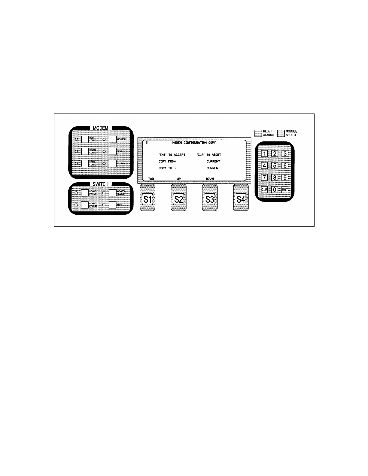
3.4.6 Configuration Copy
The Configuration Copy is a feature that enables a user to store/retrieve up to five modem and interface card
configurations in non-volatile memory. These are in addition to the current running configuration.
The interface card configurations are tagged to the slot, and are stored in the switch. The modems, on the
other hand hold their own settings. The user can copy from and copy to any configuration in memory
including the current running configuration. Source and destination configurations must be different.
When instructed to copy a configuration, the switch sends a command to the modem to copy the
configuration, and if successful, the switch updates the slot configurations as well. If the destination
configuration is the current configuration, the modem re-initializes itself and uses the new settings. The
switch interface card is only updated when the destination configuration is the current configuration.
A user must be careful not to copy onto the current configuration unless that is desired, interruptions in traffic
will occur.
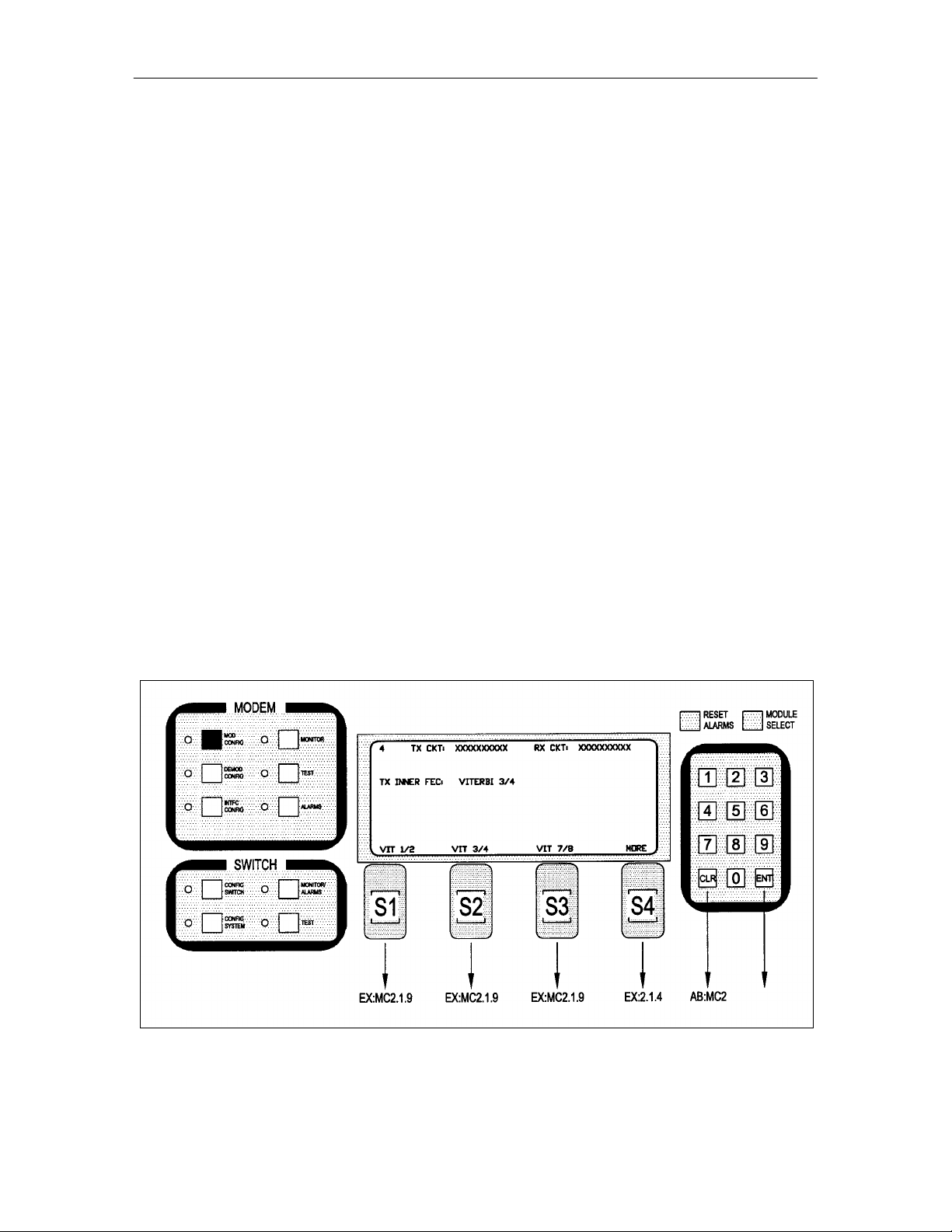
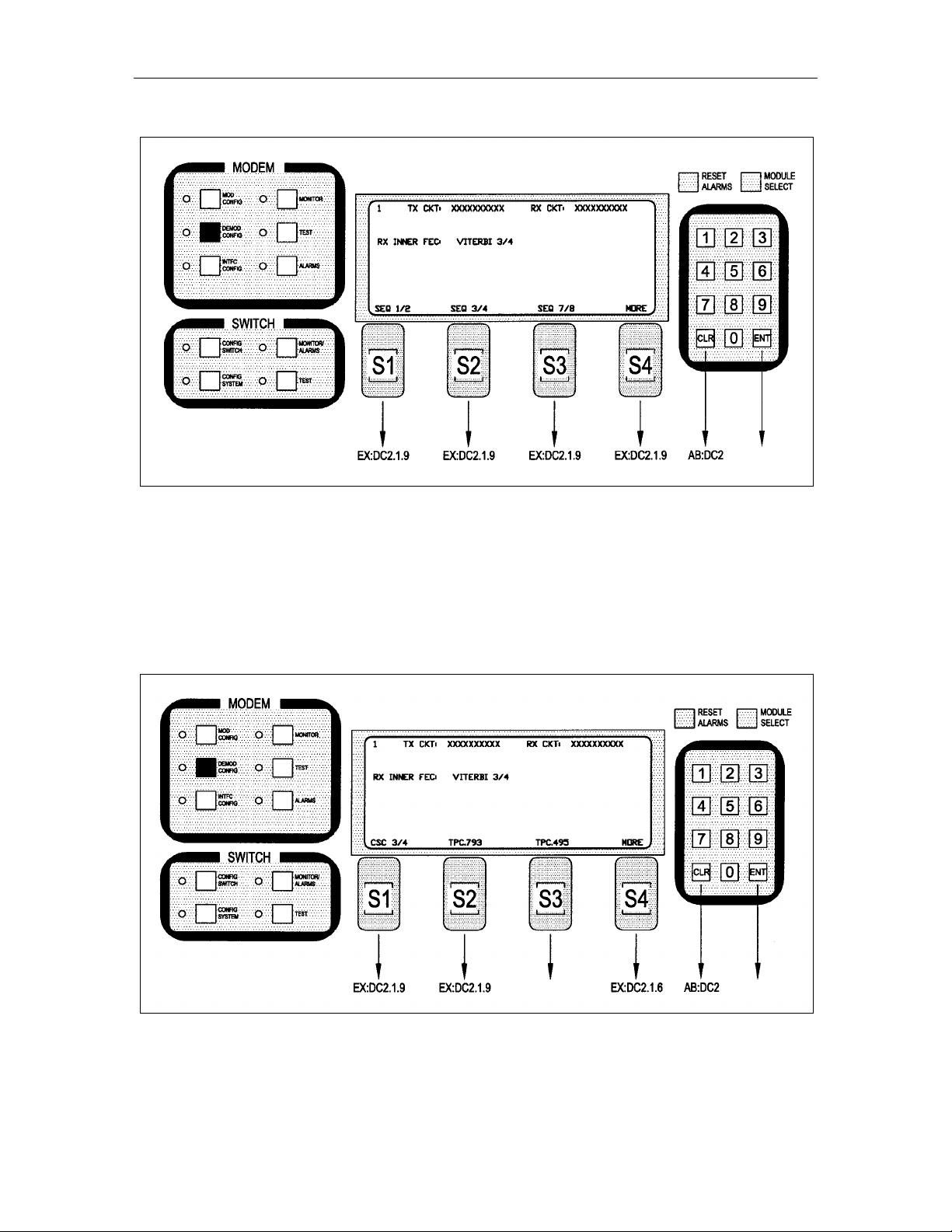
3.9.1 Function Keys
MC2.1 - Modified as follows:
Note: Inner FEC – Select VIT 1/2, VIT 3/4, VIT 7/8, SEQ 1/2, SEQ 3/4, SEQ 7/8, CSC 3/4, NONE,
TPC.793, TPC.495, TPC.325
TM058 - Rev. 2.3 v
Page 6

Addendum RCS10 Modem and Redundancy Control System
CSC 3/4 = ComStream 3/4 Rate Sequential Compatible Mode
TPC = Turbo Codec
TM058 - Rev. 2.3 vi
Page 7
Addendum RCS10 Modem and Redundancy Control System
vii
MC2.1.4 - Modified as follows:
Note: Inner FEC – Select VIT 1/2, VIT 3/4, VIT 7/8, SEQ 1/2, SEQ 3/4, SEQ 7/8, NONE, TPC.793,
TPC.495, TPC.325
CSC 3/4 = ComStream 3/4 Rate Sequential Compatible Mode
TPC = Turbo Codec
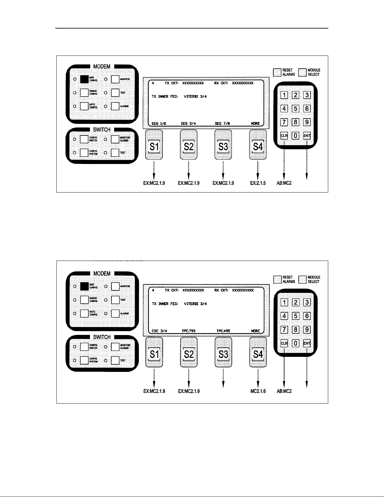
MC2.1.5 – Modified as follows:
Note: Inner FEC – Select VIT 1/2, VIT 3/4, VIT 7/8, SEQ 1/2, SEQ 3/4, SEQ 7/8, NONE, TPC.793,
TPC.495, TPC.325
CSC 3/4 = ComStream 3/4 Rate Sequential Compatible Mode
TM058 - Rev. 2.3
Page 8
Addendum RCS10 Modem and Redundancy Control System
TPC = Turbo Codec
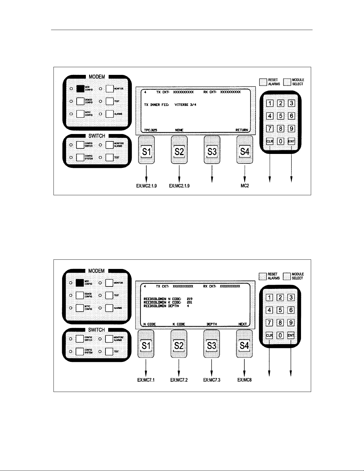
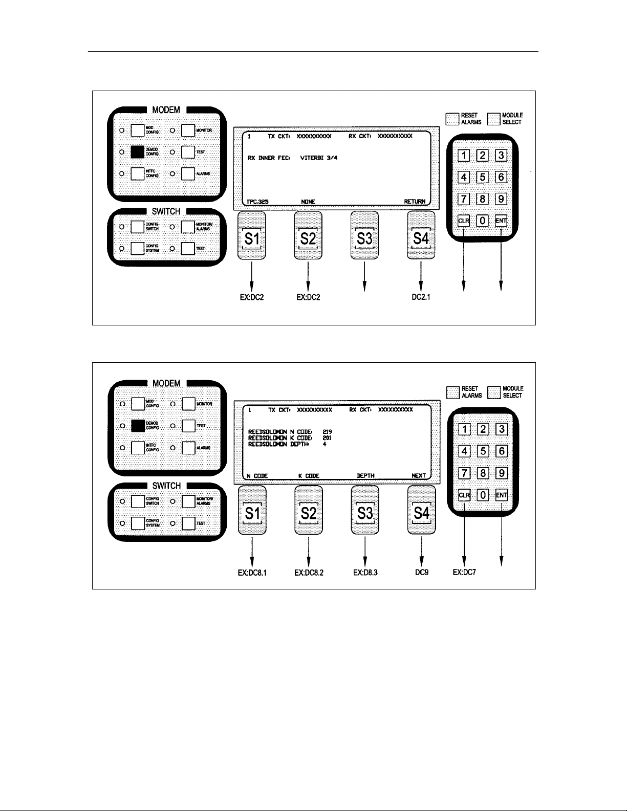
MC2.1.6– Added after Screen MC2.1.5 as follows:
Note: Inner FEC – Select VIT 1/2, VIT 3/4, VIT 7/8, SEQ 1/2, SEQ 3/4, SEQ 7/8, CSC 3/4, NONE,
TPC.793, TPC.495, TPC.325
CSC 3/4 = ComStream 3/4 Rate Sequential Compatible Mode
TPC = Turbo Codec
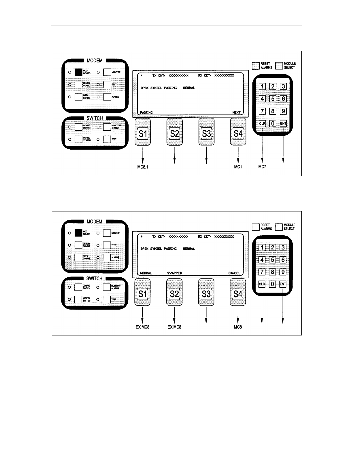
MC7 – Modified as follows:
TM058 - Rev. 2.3 viii
Page 9
Addendum RCS10 Modem and Redundancy Control System
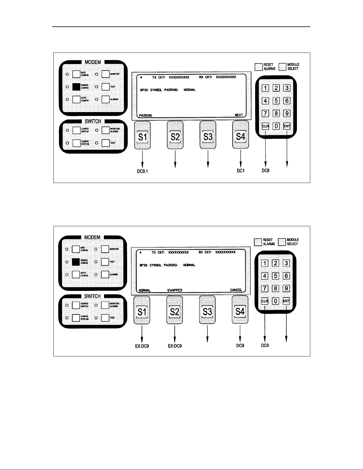
MC8 – Added after Screen MC7.3 as follows:
Note: BPSK Symbol Pairing Selection will only be displayed if BPSK Modulation is selected.
MC8.1 – Added after Screen MC8 as follows:
Note: BPSK Symbol Pairing Selection will only be displayed if BPSK Modulation is selected.
TM058 - Rev. 2.3 ix
Page 10
Addendum RCS10 Modem and Redundancy Control System
DC2.1.4 – Modified as follows:
Note: Inner FEC – Select VIT 1/2, VIT 3/4, VIT 7/8, SEQ 1/2, SEQ 3/4, SEQ 7/8, CSC 3/4, NONE,
TPC.793, TPC.495, TPC.325
CSC 3/4 = ComStream 3/ 4 Rate Sequential Compatible Mode
TPC = Turbo Codec
DC2.1.5 – Modified as follows:
Note: Inner FEC – Select VIT 1/2, VIT 3/4, VIT 7/8, SEQ 1/2, SEQ 3/4, SEQ 7/8, CSC 3/4, NONE,
TPC.793
CSC 3/4 = ComStream 3/4 Rate Sequential Compatible Mode
TM058 - Rev. 2.3 x
Page 11

Addendum RCS10 Modem and Redundancy Control System
TPC = Turbo Codec
TM058 - Rev. 2.3 xi
Page 12
Addendum RCS10 Modem and Redundancy Control System
DC2.1.6 – Added after Screen DC2.1.5 as follows:
DC8 – Modified as follows:
TM058 - Rev. 2.3 xii
Page 13
Addendum RCS10 Modem and Redundancy Control System
DC9 – Added after Screen DC8.3 as follows:
CSC 3/4 = ComStream 3/4 Rate Sequential Compatible Mode
TPC = Turbo Codec
DC9.1 – Added after Screen DC9 as follows:
CSC 3/4 = ComStream 3/4 Rate Sequential Compatible Mode
TPC = Turbo Codec
TM058 - Rev. 2.3 xiii
Page 14
Addendum RCS10 Modem and Redundancy Control System
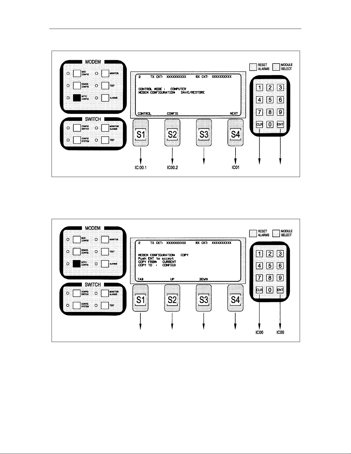
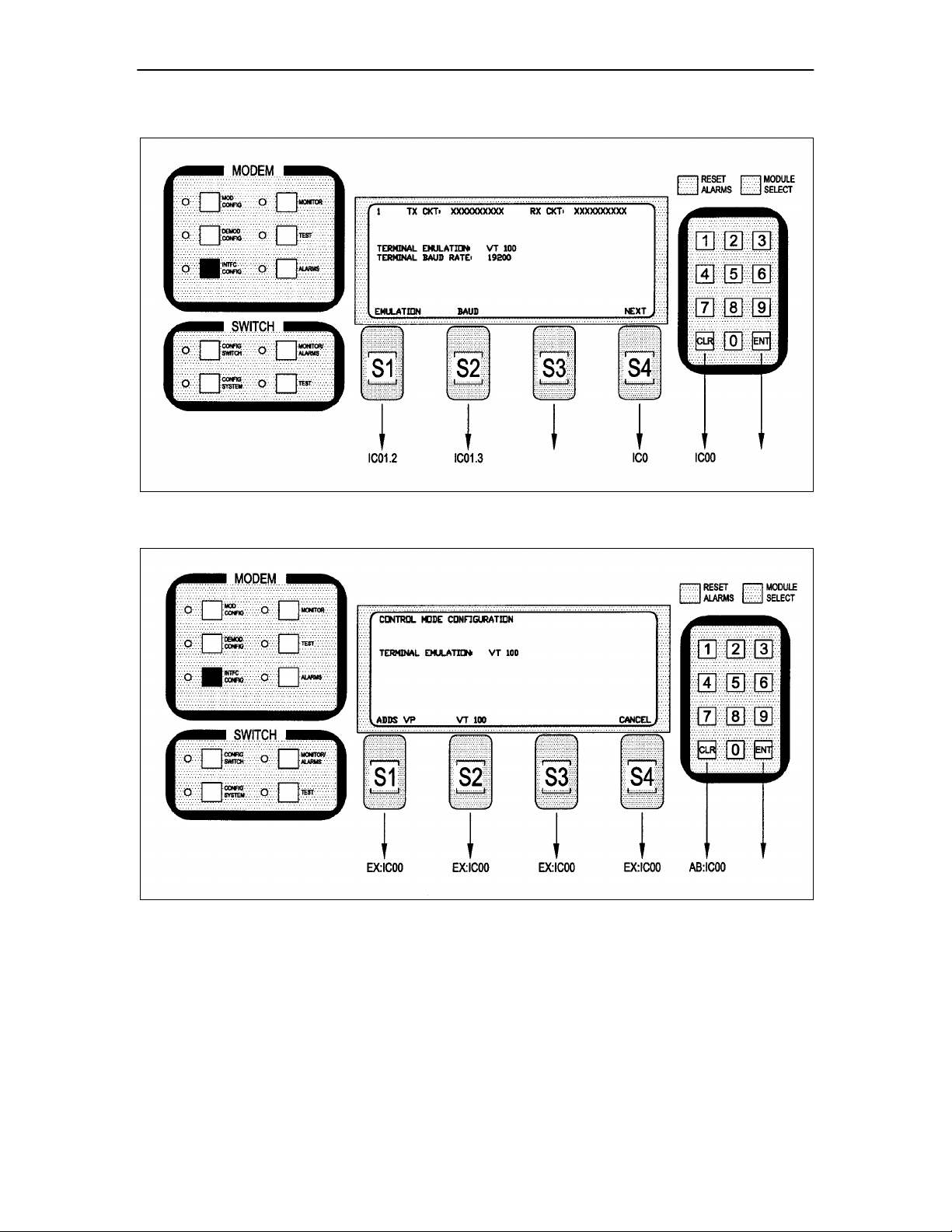
IC00 – Modified as follows:
Note: Select Modem Control Mode or Configuration Copy Feature. Up to five configurations can be
stored/retrieved.
IC00.2 – Added after Screen IC00.1 as follows:
Note: Up to five configurations, in addition to the current settings, can be stored/retrieved.
TM058 - Rev. 2.3 xiv
Page 15
Addendum RCS10 Modem and Redundancy Control System
IC01 – Added after Screen IC00.2 as follows:
IC00.2 – Changes its name to IC01.2 and is modified as follows:
IC00.3 – Changes its name to IC01.3.
IC00.4 – Changes its name to IC01.4.
IC00.5 – Changes its name to IC01.5.
TM058 - Rev. 2.3 xv
Page 16

Addendum RCS10 Modem and Redundancy Control System
B.1.4 Global Response Operational Codes
Change the last Modem Response Error Codes Description and Opcode of the first group to
MPARM_AUPCDEFPOWER_ERROR 0x43F.
Add the following Modem Response Error Code Descriptions and Opcodes to the bottom of the first group
(following MPARM_AUPCDEFPOWER_ERROR 0x43F):
MPARM_CONFIGURATIONSOURCE_ERROR 0x440
MPARM_CONFIGURATIONDESTINATION_ERROR 0x441
MPARM_CONFIGURATION_ERROR 0x442
B.2 Remote Port Packet Structure
Modulator Opcode <2400H>
Change <1> Convolutional Encoder (18 =… to:
18 = Trellis 8/9 Rate, 19 = Comstream SEQ 3/4 rate 20 = TPC.793 2D, 21 = TPC.495 3D, 22 = TPC.325 3D)
Modulator Opcode <2607H>
Change <1> Convolutional Encoder (18 =… to:
18 = Trellis 8/9 Rate, 19 = Comstream SEQ 3/4 rate 20 = TPC.793 2D, 21 = TPC.495 3D, 22 = TPC.325 3D)
Demodulator Opcode <2401H>
Change <2> Sweep Delay to:
(Binary value, 0.1 second steps. Reserved)
Change <1> Convolutional Decoder (18 =… to:
18 = Trellis 8/9 Rate, 19 = Comstream SEQ 3/4 rate 20 = TPC.793 2D, 21 = TPC.495 3D, 22 = TPC.325 3D)
Change <1> Alarm 5 Masks to:
(Bit 0 = Trellis Decoder Lock, Bit 1 = FM DSP Lock Mask, Bit 2 = T1 signaling fault, Bit 3 = Turbo Codec
lock fault, Bits 4 – 7 = Spares)
Change Status Bytes <1> Alarm 5 to:
(Bit 0 = Trellis Decoder Lock, Bit 1 = FM DSP Lock Mask, Bit 2 = T1 signaling fault, Bit 3 = Turbo Codec
lock fault, Bits 4 – 7 = Spares)
Add to the end of Status Bytes:
<1> Spare
<4> Symbol Rate (Binary Value, 1bps steps)
TM058 - Rev. 2.3 xvi
Page 17

Addendum RCS10 Modem and Redundancy Control System
Demodulator Opcode <240CH>
Change Status Bytes <1> Alarm 5 to:
(Bit 0 = Trellis Decoder Lock, Bit 1 = FM DSP Lock Mask, Bit 2 = T1 signaling fault, Bit 3 = Turbo Codec
lock fault, Bits 4 – 7 = Spares)
Add to the end of Status Bytes:
<1> Spare
<4> Symbol Rate (Binary Value, 1bps steps)
Demodulator Opcode <2409H>
Change <2> Sweep Delay to:
(Binary value, 0.1 second steps. Reserved)
Change <1> Convolutional Decoder (18 =… to:
18 = Trellis 8/9 Rate, 19 = Comstream SEQ 3/4 rate 20 = TPC.793 2D, 21 = TPC.495 3D, 22 = TPC.325 3D)
Change <1> Alarm 5 Masks to:
(Bit 0 = Trellis Decoder Lock, Bit 1 = FM DSP Lock Mask, Bit 2 = T1 signaling fault, Bit 3 = Turbo Codec
lock fault, Bits 4 – 7 = Spares)
Demodulator Opcode <2A08H>
Change <1> Convolutional Decoder (18 =… to:
18 = Trellis 8/9 Rate, 19 = Comstream SEQ 3/4 rate 20 = TPC.793 2D, 21 = TPC.495 3D, 22 = TPC.325 3D)
Add to the end of Demodulator Opcodes:
Opcode: <2C0BH> Command modem terminal emulation
<1> Emulation Mode (0 = Add viewpoint, 1 = VT 100, 2 = WYSE50)
Opcode: <2C0CH> Command modem terminal baud rate
<1> Baud Rate (0 = 300 baud, 1 = 600 baud, 2 = 1200 baud, 3 = 2400 baud, 4 = 800 baud, 5 =
9600 baud, 6 = 19200 baud, 7 = 38400 baud)
Opcode: <2C0DH> Command modem configuration copy
<1> Source Configuration (0 = current, 1 = configuration 1, 2 = configuration 2, 3 =
configuration 3, 4 = configuration 4, 5 = configuration 5)
<1> Destination Configuration (0 = current, 1 = configuration 1, 2 = configuration 2, 3 =
configuration 3, 4 = configuration 4, 5 = configuration 5)
Note: Source and destination configuration configurations must be different. Error 0x441 will be
returned if they are the same.
TM058 - Rev. 2.3 xvii
Page 18

Addendum RCS10 Modem and Redundancy Control System
Radyne Private MIB for RCS10
Add to the end of line:
RadRCS10_TxConvolutionalEncoder OBJECT-TYPE
SYNTAX Integer {
Comstream_seq_3_4(19)
,
tpc793_2D(20),
tpc495_3D(21),
tpc325_3D(22)
Add to the end of line:
DESCRIPTION
“Selects…
…for future use. Sequential, turbo codec, and trellis are installed options.”
Delete from line:
RadRCS10_TxModulationType OBJECT-TYPE
DESCRIPTION
“Selects…
16QAM modulation is not yet implemented.
Add to the end of line:
RadRCS10_RxConvolutionalDecoder OBJECT-TYPE
SYNTAX Integer {
Comstream_seq_3_4(19)
,
tpc793_2D(20),
tpc495_3D(21),
tpc325_3D(22)
Add to the end of line:
DESCRIPTION
“Selects…
…for future use. Sequential, turbo codec, and trellis are installed options.”
Replace the following line:
RadRCS10_RxAlarm5Mask OBJECT-TYPE
SYNTAX Integer…
Bit 1..7 = Spares
With:
TM058 - Rev. 2.3 xviii
Page 19

Addendum RCS10 Modem and Redundancy Control System
Bit 1 = FMDSP Lock
Bit 2 = T1 signaling fault
Bit 3 = Turbo codec lock fault
Bits 4 – 7 = Spares
Insert after the following line:
RadRCS10_RxAlarm5Status OBJECT-TYPE
DESCRIPTION
Bit 0 = Trellis decoder lock
With:
Bit 1 = FMDSP Lock
Bit 2 = T1 signaling fault
Bit 3 = Turbo codec lock fault
Change the following line:
RadRCS10_RxAlarm5Status OBJECT-TYPE
DESCRIPTION
Bits 1 – 7 = Spares
To:
Bits 4 – 7 = Spares
Turning On/Off the Fairchild Compatible Scrambler/Descrambler
For the Mod
1. Go to the ‘Mod Confg’ Screen
2. Press the ‘Next’ Key 4 times.
3. ‘Type’ will appear. Press ‘More’ until you see ‘V.35 (FC)’.
4. Press ‘On’ or ‘Off’ as applicable.
For the Demod
1. Go to the ‘Demod Confg’ Screen
2. Press the ‘Next’ Key 5 times.
3. ‘Type’ will appear. Press ‘More’ until you see ‘V.35 (FC)’.
4. Press ‘On’ or ‘Off’ as applicable.
Swapping the Symbol for BPSK
For the Mod
1. Go to the ‘Mod Confg’ Screen
2. Press the ‘Next’ Key 7 times.
3. ‘Pairing’ will appear. Press ‘Swapped’ or ‘Normal’ as applicable.
For the Demod
TM058 - Rev. 2.3 xix
Page 20
Addendum RCS10 Modem and Redundancy Control System
1. Go to the ‘Demod Confg’ Screen
2. Press the ‘Next’ Key 8 times.
3. ‘Pairing’ will appear. Press ‘Swapped’ or ‘Normal’ as applicable.
Storing and Recalling 5 Configurations
1. From “Interface”, go to the ‘Confg’. The ‘Modem Configuration Copy’ Screen (Refer to Figure 1) will
appear.
Figure 1.
2. Press the ‘Tab’ Button to select between ‘Copy from:’ and ‘Copy to:’.
3. Press the ‘Up’ or ’Down’ Buttons to select ‘Confg1‘ - ‘Confg5’ (the five configurations).
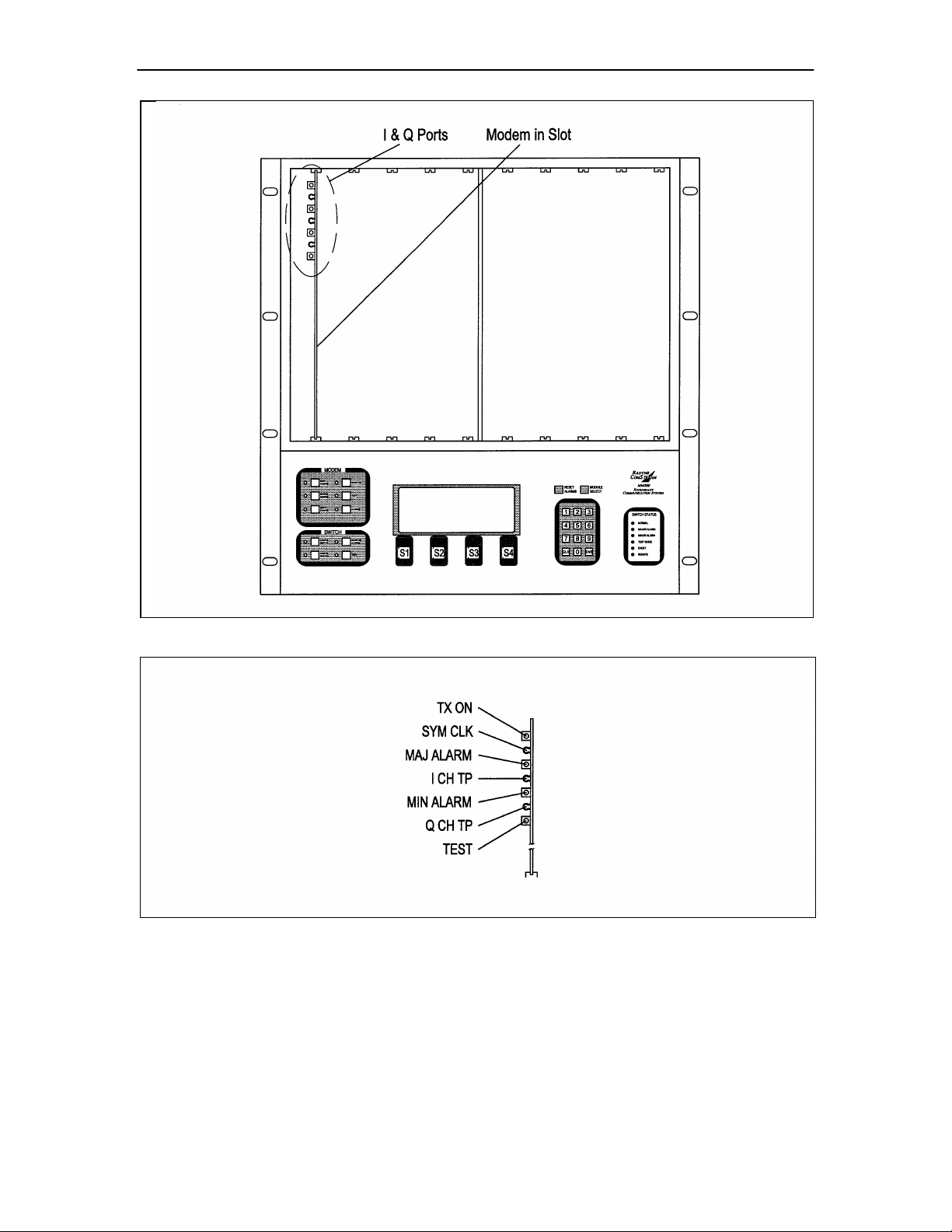
DMD10 I & Q Ports (Refer to Figures 2 and 3)
TM058 - Rev. 2.3 xx
Page 21
Addendum RCS10 Modem and Redundancy Control System
Figure 2.
Figure 3.
TM058 - Rev. 2.3 xxi
Page 22

RCS10 Redundant Communication System Table of Contents
Table of Contents
1.1 Introduction………………….……………………………………………………………………………….. 1-1
1.2 External Reference…………………………………..……………………………………………………… 1-1
1.3 RCS10 System Functional Block Diagram..……………………………………………………………… 1-2
2.0 Installation Requirements..….……………………………………………………………………………… 2-1
2.1 Unpacking the System…....………………………………………………………………………………… 2-1
2.1.1 List of
Items.………..…….……………………………………..…………………………………………… 2-1
2.1.2 In Case of Shipping Damage…………………………………………………………………….…………. 2-1
2.1.3 Test Data Sheet..…..………………………………………………………………………………………… 2-1
2.2 Site Considerations..………………………………………………………………………………………… 2-1
2.2.1 Power
Sources…...…….……..…………………………….……………………………………..………… 2-1
2.3 Rack Mounting…………..…………………………………………………………………………………… 2-2
2.3.1 DMD10 (Modem) Installation into the RCS10 Chassis…………………………………………………
2-2
2.4 Configuring the System…….…..…………………………………………………………………………… 2-2
2.4.1 Modem
Connections………………………………………………………………………………………… 2-3
2.4.2 Connector Pinout Tables……………………………………………………………………………………
2-3
2.4.3 Universal Interface Module
Connectors…………………………………………………………………… 2-3
2.5 External Reference Card Section…………………………………………………………………………2-13
2.5.1 Ethernet Interface……………………………………………………………………………….…………
2-13
3.1 Operating Procedures….…………………………………………………………………………………… 3-1
3.1.1 Front Panel Control….……..………………………………………………………………………………
3-1
TM058 - Rev. 2.3 xx
Page 23

RCS10 M:N Redundant Communication System Table of Contents
3.1.2 Front Panel Layout and Features….………………………………………………………………………
3-1
3.1.3 Front Panel LCD
Display…………………………………………………………………………………… 3-1
3.1.4 Front Panel LCD
Indicators………………………………………………………………………………… 3-1
3.1.5 RCS10 Modem Section LED Indicators…………………………………………………………………
3-4
3.1.6 Redundancy Switch Front Panel Section LED Indicators………………………………………………
3-4
3.1.7 Menu LED
Indicators………………………………………………………………………………………… 3-4
3.1.7.1 Switch Status LED Indicators……………………………………………………………………………… 3-5
3.1.8 Local/Remote
Control……………………..………………………………………………………………… 3-5
3.1.9 Terminal Control……………………………………………………………………………………………
3-5
3.1.10 Remote M&C Interface…………………………………………………………………………………….. 3-5
3.1.11 SNMP Control……………………………………………………………………………………………….. 3-5
3.1.12 Manual/Automatic Backup Modes………………………………………………………………………… 3-6
3.1.13 Standby Modes……………………………………………………………………………………………… 3-6
3.1.14 Test Port Operation (Operational on Backup Modem 2 Only)…………………………………………. 3-6
3.1.15 Backup/Online……………………………………………………………………………………………….. 3-6
3.2 Guide to Front Panel Monitor and Control………………………………………………………………… 3-7
3.2.1 Remote Port
Control………………………………………………………………………………………… 3-7
3.2.2 Terminal Port Control………………………....……………………………………………………
…….. 3-7
3.3 Backup Handler……………………………………………………………………………………………… 3-7
3.3.1 1:N or 2:N
Switching………………………………………………………………………………………… 3-8
TM058 - Rev. 2.3
xxi
Page 24

RCS10 M:N Redundant Communication System Table of Contents
3.4 RCS10 ‘Learn’ Feature……………………………………………………………………………………… 3-8
3.4.1
Description……………………………………………………………………………………………………. 3-8
3.4.2 Alarms and
Reports…………………………………………………………………………………………. 3-9
3.4.3 Service
Mode………………………………………………………………………………………………… 3-17
3.4.4 Interface Card (I/O) Configuration………………………………………………………………………….
3-17
3.4.5 Modem/I/O/Switch
Communications………………………………………………………………………. 3-17
3.5 Modem Checkout and Initial Power-Up…....……………………………………………………………… 3-17
3.5.1 RCS10 Front Panel Data Entry
Screens..…..…………………………………………………………….. 3-18
3.5.2 Basic Front Panel
Controls……….………………………………………………………………………… 3-18
3.5.2.1 Changing Parameters from the Front Panel……………………………………………………………… 3-18
3.5.2.2 Moving to the Next Screen in a Menu Tree……………………………………………………………… 3-19
3.5.2.3 Mov ing to the Previous Screen in a Menu Tree………………………………………………………… 3-19
3.6 Summary of Basic Front Panel Controls………………………………………………………………… 3-19
3.7 RCS10 Strap Codes (Quick Set Keys)…………………………………………………………………… 3-19
3.8 RCS10 Sample Operation Examples…………………………………………………………………… 3-23
3.9 RCS10 Command and Status Parameters (Front Panel Menu Screens)……………………………. 3-28
3.9.1 Function
Keys……………………………………………………………………………………………….. 3-28
3.10 Demodulator Configuration………………………………………………………………………………… 3-54
3.11 Interface Configuration Front Panel Menu Screens……………………………..…………………..….. 3-75
3.12 Modem Monitor Configuration Front Panel Menu Screens……………………..………………………3-101
3.13 Modem Test Configuration Front Panel Menu Screens…………………………..…………………….3-104
TM058 - Rev. 2.3
xxii
Page 25

RCS10 M:N Redundant Communication System Table of Contents
3.14 Modem Alarms Configuration Front Panel Menu Screens……………………………..……………….3-107
3.15 Switch Configuration Front Panel Menu Screens…………………………………………....…………
3-124
3.16 Switch Section, System Configuration Screens……………………….………………………………. 3-143
3.17 Switch Monitor/Alarms…………………………………………………………………………………….. 3-157
3.18 Switch Test…………………………………………………………………………………………………..3-161
4.0 Periodic Maintenance……………………..………………………………………………………………… 4-1
4.1 Fuse Replacement…………………………………………………………………………………………. 4-1
4.1.1 Redundant Power Supply Fuse Replacement…………………………………………………………..
4-1
4.2 Troubleshooting….………………..…………………..…………………………………………….………. 4-1
4.2.1 DMD10 Fault
Philosophy…………………………………………………………………………………… 4-2
4.2.2 Alarm
Masks………………….……………………………………………………………………………… 4-2
4.2.3 Major
Alarms…………..………..…………………………………………………………………………… 4-2
4.2.4 Minor
Alarms…………………………………………………………………………………………………. 4-2
4.2.5 Common
Alarms…………………………………………………………………………………………….. 4-2
4.2.6 Backward
Alarms……………………………………………………………………………………………. 4-2
4.2.7 Latched
Alarms……………………………………………………………………………………………… 4-2
4.3 DMD10 Fault Tree Matrices………………………………………………………………………………… 4-2
4.3.1 Interpreting the Fault Tree Matrices……………………………………………………………………….. 4-2
4.4 IBS Fault Conditions and Actions………………………………………………………………………….. 4-5
5.0 DMD10 Modem Principles of Operation…………………………..…………………………….………… 5-1
5.1 Universal Interface Module…………………..……………………………………………………….……. 5-1
TM058 - Rev. 2.3
xxiii
Page 26

RCS10 M:N Redundant Communication System Table of Contents
5.1.1 Synchronous Interface ……………….…….………………………….…………………………………… 5-1
5.1.2 G.703 Interface……………………………………………………………………………………………… 5-1
5.2 96 Kbps ESC Port…………………………..…………………………………………………………..…… 5-2
5.3 Terrestrial Loopback………..…………………………………..…………………………………………… 5-2
5.4 Modem Status………………………..………………………………………………………….…………… 5-2
5.5 Baseband Processor Card………………………………………………………………………………… 5-2
5.5.1 Baseband
Processing………………………………………………………………………………………. 5-2
5.5.2 Tx Baseband
Processing…………………………………………………………………………………… 5-2
5.5.3 Rx Baseband Processing…………………………………………………………………………………..
5-3
5.5.4 Clock
Selection……………………………………………………………………………………………… 5-3
5.5.5 Baseband
Framing/Multiplexing…………………………………………………………………………… 5-3
5.5.5.1 Standard IBS Mode…………………………………………………………………………………………. 5-4
5.5.5.2 Enhanced Multiplexer Mode……………………………………………………………………………….. 5-5
5.6 Additional Clocking Data……………………………………………………………………………………. 5-5
5.7 Monitor and Control Subsystem…………………………………………………………………………… 5-8
5.8 Universal Modem……………………………………………………………………………………………. 5-8
5.8.1 Modulator….…………………………………………………………………………………………………
5-9
5.8.2 Demodulator………………………………………………………………………………………………….
5-9
5.9 Drop and Insert……………………………………………………………………………………………… 5-13
5.9.1 Drop Only……………………………………………………………………………………………………
5-13
5.9.2 Insert Only……………………………………………………………………………………………………
5-13
TM058 - Rev. 2.3
xxiv
Page 27

RCS10 M:N Redundant Communication System Table of Contents
5.10 Mode Selection……………………………………………………………………………………………….5-16
5.11 Multidestinational Systems………………………………………………………………………………… 5-17
5.12 Reed-Solomon Codec……………………………………………………………………………………… 5-17
5.12.1 Operation in the DMD10…………………………………………………………………………………… 5-17
5.12.2 Reed-Solomon Code Rate.…………………………………………………………………………………5-17
5.12.3 Interleaving………………………………………………………………………………………………… 5-18
Appendix A - RCS10 Technical Specifications.…..…………………………………………………………..…… A-1
Appendix B - Modem Remote Communications Specification…………………………………………………….B-1
Appendix C – RCS10 Remote Communications Specification……………………………………………………C-1
Addendum A – RCS10/RCS10L Simple Network Management Protocol (SNMP)……………………………..AD-1
TM058 - Rev. 2.3
xxv
Page 28

Appendix A RCS10 Technical Specifications
Solomon
Section 1 - RCS10 Redundant Communication System Description
1.1 Introduction
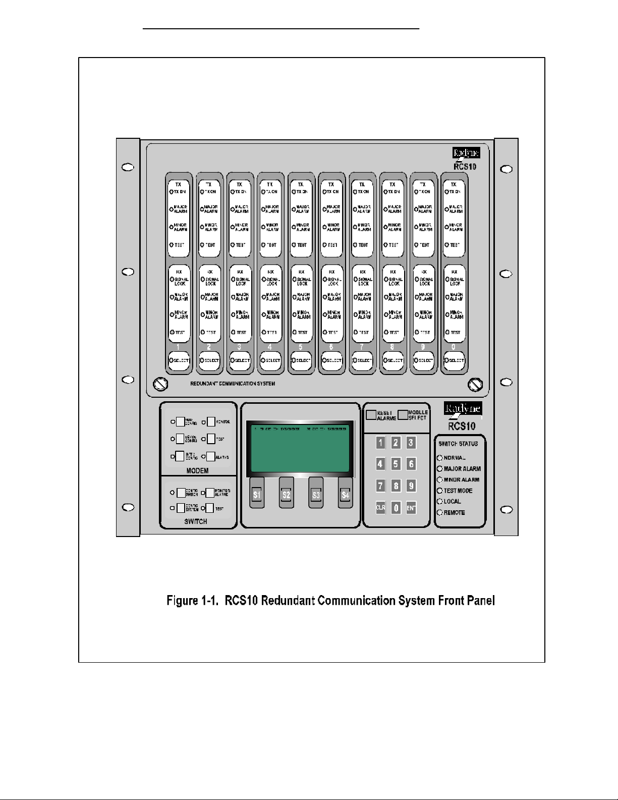
As shown in Figure 1-1, Radyne ComStream's RCS10 is
a complete, self-contained modem system with all
modems, terrestrial interfaces and redundancy switch
functions included in a single equipment cabinet that is
10 rack units high (17.5 inches). This compact and
versatile common equipment package is unique and
offers unsurpassed performance, reliability and flexibility.
In addition to full support for Intelsat's IDR/IBS services,
the system may be operated in closed networks.
The built-in M:N Redundancy Switch is an intelligent
microcomputer controlled system, capable of controlling
up to ten DMD10 modems in a variety of configurations.
The switch can be operated automatically, in which case
an automatic back-up of a failed on-line modem occurs
after a preprogrammed delay. The switch may also be
operated manually, allowing the operator to manually
switch in the backup unit. Front panel controls and
indicators provide for auto/manual configuration, as well
as display of online/off-line status information for all
modems in the redundancy configuration.
All switch and modem operating parameters, such as
variable data rates and selectable IBS/IDR framing, are easily set and changed by the operator.
The modem and redundancy switch monitor and control functions are available at the front panel of
the system (Refer to Section 3). All functions may also be accessed through a terminal or a
personal computer via a serial link (RS485 or Ethernet) for complete remote monitoring and control
capability.
RCS10 FEATURES
• Ten Modems and a Redundancy Switch in a
10 Rack Unit (17.5 inches) enclosure
• Up to 30 Modems in One Rack
• Large Display with Easy-to-use Menu Structure
• Built-in M:N Redundancy Switch
• Dual Redundant Power Supplies
• Fewer Cables Simplifies Installation
• Fully-Compliant with IESS 308/309
• Operation from 9.6 Kbps to 8.448 Mbps
• Options Include Drop and Insert, ReedCodec, Sequential Decoder, Trellis Coded
Modulation, ESC, OQPSK, 8PSK Modulation and
Ethernet Remote M&C.
When used with the optional IFC10 IF Combiner/Splitter system, the RCS10 system provides all of
the signal combiners and splitters, terminations and interconnecting cables that are necessary to
connect any combination of up to nine active modems to nine independent uplink and nine
independent downlink transponders. Refer to Figure 1-3, RCS10 System Block Diagram for a basic
overview of the RCS10 system components.
1.2 External Reference
The External Reference Module, located in slot 10 on the far left side of the RCS10 rear panel (See
Figure 1-2), has one External IF Reference input which is distributed to all ten DMD1O modems.
Each modem’s on-board system oscillator can be individually locked to the external reference.
Additionally, the external reference module can be equipped with a 10-7 high stability reference
oscillator which is distributed to all ten DMD10 modems, thus providing a low-cost high-stability
option. An External IF reference output is also provided for distribution to other equipment.
Also, the external reference has one BNC clock input which is distributed to all ten modems. Each
modem control can independently select this external clock as its Tx clock and/or RX buffered
clock source.
Page 1-1
Page 29

RCS10 Technical Specifications Appendix A
1.3 RCS10 System Functional Block Diagram
As shown in Figure 1-3, the RCS10 is comprised of five functional sections. Refer to Section 5,
Principles of Operation, for detailed information on the DMD10 modem principles of operation. The
functional areas of the RSC10 are as follows:
• IF Switch Section
• The DMD10 Modem Section
• The Data Switch Section
• The Switch CPU Section
• The Front Panel Interface
Page 1-2
Page 30
Appendix A RCS10 Technical Specifications
Page A -3
Page 31

RCS10 Technical Specifications Appendix A
Page 1-4
Page 32

Appendix A RCS10 Technical Specifications
Page A -5
Page 33

Appendix A RCS10 Technical Specifications
Section 2 - Installation
2.0 Installation Requirements
This chapter instructs the user in the methods for setting up and installing an RCS10 Redundant
Communication System into a Satellite Modem system.
2.1 Unpacking the System
Unseal the shipping cartons taking care not to damage the cartons, the packing material or the
equipment inside. The cartons and the packing material should be saved in the event that an
RCS10 will need to be reshipped. Examine the exterior of the units for any possible shipping
damage.
2.1.1 List of Items
Carefully remove the units from the cart ons. In addition to this manual, be sure that the following
items are present:
• RCS10 Redundant Communication System
• 2 AC Power Cords
• RCS10 System Test Data Sheet
2.1.2 In Case of Shipping Damage
If any shipping damage is discovered on any of the above listed equipment, promptly contact the
transporter and file a damage claim. The shipping company is responsible for any damage caused
during shipping. Radyne ComStream Corporation should also be contacted.
Damage as a result of transportation is not covered under the Radyne ComStream Corporation
Warranty. Refer to the Warranty section in the front of this manual for further information.
The procedure for returning faulty or damaged equipment is contained in the warranty section in the
front of this manual.
2.1.3 Test Data Sheet
Each RCS10 Redundant Communication System is shipped with a Test Data Sheet. This report
contains information on the results of the Switch quality control testing. The report also includes
information pertaining to the system settings that were made at the factory. Radyne ComStream
Corporation recommends that the user save this report for future reference.
2.2 Site Considerations
Adequate site planning and preparation simplifies the installation process and results in a more
reliable system.
The user should ensure that the site has adequate electrical power, environmental controls and
protection against sources of electrical radiation and interference.
2.2.1 Power Sources
The power sources should be properly grounded and as free as possible from electrical interference.
If a redundant configuration is to be used, then each power cord on the RCS10 must be plugged into
its own separate power circuit. Each circuit must have its own independent circuit breaker.
Grounding is ac hieved automatically when the three-prong power plug is inserted into a power
receptacle. This should be checked by testing that there is no voltage present between the chassis
of the Switch and the power line ground.
Page A -1
Page 34

RCS10 Technical Specifications Appendix A
The protective ground must not be bypassed with a three-prong to two-prong adapter or defeated in
any way. Defeating the ground may result in operator Injury or damage to the system.
2.3 Rack Mounting
To allow for the easy installation of cables and adequate air circulation through the units, a
minimum of six inches of clearance must be provided at the sides and rear of the units. In addition,
the RCS10 requires a minimum of 1-3/4 inches (1U) of clearance at the top of the unit.
The RCS10, when fully populated, weighs approximately 100 lbs. When installing into a rack
enclosure, a minimum of two technicians are required to minimize personal hazard.
2.3.1 DMD10 (Modem) Installation into the RCS10 Chassis
The RCS10 is shipped with the Modems (DMD10s) and External Reference Card packaged
separately for shipping purposes. All modems are universal and may be installed into any slot (1-9).
The External Reference Card is installed in slot 10.
2.4 Configuring the system
If either AC line cord remains connected to the RCS10, dangerous AC voltages will be present
within the unit and the cooling fans will also be operational. Although AC power is not present on
the backplane, care must be taken when installing or removing a plug-in module since DC voltages
will be present.
Before powering up the RCS10 or attaching cables to J12 (Sync Data RS422/RS485/V.35), the
following steps MUST be verified in order to avoid damage to the equipment. Ensure the following:
1. The cables must be wired correctly. Refer to Table 2-1, J12 Sync Data,
RS422/RS485/V.35;
2. The External Interface is programmed or supports the appropriate Interface type: RS232,
RS422, or V.35;
3. The Universal Interface Module (UIM) is configured for the appropriate Interface type:
RS232, RS422 or V.35.
Page 1-2
Page 35

This is EXTREMELY IMPORTANT as the Interface pins operate at different voltage levels
depending upon the Interface type selected. SERIOUS DAMAGE may occur, for example, if
the External Interface is operating at V.35 voltage levels and the Universal Interface is
configured for RS422 voltage leve ls.
2.4.1 Modem Connections
All modem connections are made to labeled connectors located on the rear of the unit: The
connector definitions and pinout tables are shown below, and are those on the RCS10 unit and
Universal Interface Modules. Any connec tion interfacing to the modem must be the appropriate
mating connector. Refer to Figures 2-2 and 2-3 to locate the rear panel connectors.
2.4.2 Connector Pinout Tables
The following paragraphs and tables contain the pinout information for the various data/IF connectors
located on the rear panel of the RCS10.
2.4.3 Universal Interface Module (UIM) Connectors
The RCS10 chassis is shipped with the Universal Interface Modules installed. The following table
lists the signals, descriptions and directions for the connectors located on the UIM. Refer to Figure
2-2 for the three possible UIM configurations.
J1 - SD - SEND DATA
Unbalanced Send Data (SD) BNC connector located on the Interface Module. Data into the modem.
J2 - DDO - DROP DATA OUT
Unbalanced Drop Data Out (DDO) BNC connector located on the Interface Module.
J3 - IDI - INSERT DATA IN
Unbalanced Insert Data In (IDI) BNC connector located on the Interface Module.
J4 - RD - RECEIVE DATA
Unbalanced Receive Data (RD) BNC connector located on the Interface Module. Data out of the
modem.
J5 - G.703 (Balanced) 15-Pin Female ‘D’ Connector.
J7 - ESC 8K DATA INTERFACE - 15-Pin Female ‘D’
J8 - ESC VOICE/64K DATA - 9-Pin Female ‘D’
J9 - ESC ALARM INTERFACE - 25-Pin Female ‘D’
J10 - ASYNC DATA - 9-Pin ‘D’ Female.
J11 - MODEM STATUS - 15-Pin ‘D’ Female.
J12 - SYNC DATA, RS422/RS485/RS232/V.35 - 37-Pin Female Synchronous Data Connector.
Page A -3
Page 36

RCS10 Technical Specifications Appendix A
switch position
Page 1-4
Black is the
Page 37

Page A -5
Page 38

RCS10 Technical Specifications Appendix A
Figure 2-3. RCS10 Rear Panel
(Shown with the RCS10 ESC Options Installed)
Page 1-6
Page 39

Page A -7
Page 40

RCS10 Technical Specifications Appendix A
NOTE: See Warning on Page 2-2. Verify Steps 1 through 3 Before Attaching Data Cables.
Table 2–1.
J12 - Sync Data RS422/RS485/V.35 - 37-Pin Female
Pin Number Signal Description Direction
3 TXO-A Transmit Octet (-) Input
21 TXO-B Transmit Octet (+) Input
4 SD-A Send Data A (-) Input
22 SD-B Send Data B (+) Input
5 ST-A Send Timing A (-) Output
23 ST-B Send Timing B (+) Output
6 RD-A Receive Data A (-) Output
24 RD-B Receive Data B (+) Output
7 RS-A Request to Send A (-) Input
25 RS-B Request to Send B (+) Input
8 RT -A Receive Timing A (-) Output
26 RT -B Receive Timing B (+) Output
9 CS-A Clear to Send A (-) Output
10 MF Mod Fault - Open
Output
Collector
28 DF Demod Fault - Open
Output
Collector
27 CS-B Clear to Send B (+) Output
11 DM-A Data Mode A (-) Output
29 DM-B Data Mode B (+) Output
13 RR-A Receiver Ready A (-) Output
31 RR-B Receiver Ready B (+) Output
15 EXC-A External Clock A (-) Input
33 EXC-B External Clock B (+) Input
16 RX -0-A Receive Octet A (-) Output
34 RX -0-B Receive Octet B (+) Output
17 TT-A Terminal Timing A (-) Input
35 TT-B Terminal Timing B (+) Input
1, 19, 20, 37 GND Signal Ground
Page 1-8
Page 41

J5 - G.703 (Balanced)
Table 2-2 below lists the pinouts and signal definitions for the G.703 (Balanced) 15-pin
connector.
Table 2-2.
J5 - G.703 (Balanced) 15-Pin Female ‘D’ Connector
Pin No. Signal Name Signal Direction
1 Send Data (-) SD-A Input
9 Send Data (+) SD-B Input
3 Receive Data A (-) RD-A Output
11 Receive Data B (+) RD-B Output
12 Drop Data Out (-) DDO-A Output
5 Drop Data Out (+) DDO-B Output
13 Insert Data In (-) EXC (-) IDI-A Input
6 Insert Data In (+) EXC (+) IDI-B Input
14 MF Mod Fault Open
Output
Collector
15 DF Demod Fault Open
Output
Collector
7 G703-EXC-A External Clock A (-) Input
8 G703-EXC-B External Clock B (+) Input
2, 4 GND Signal Ground
J7 - ESC 8K Data Interface
Table 2-3
J7 - ESC 8K Data Interface - 15-Pin Female ‘D’
Pin No. Signal Description Direction
1 ESCRXO-B Rx Octet-B Output
2 ESCRXC-B Rx Clock-B Output
3 ESCRXD-B Rx Data-B Output
4 NC
Page A -9
Page 42

RCS10 Technical Specifications Appendix A
5 NC
6 ESCTXD-A Tx Data-A Input
7 ESCTXC-A Tx Clock-A Output
8 ESCTXO-A Tx Oc tet-A Output
9 ESCRXO-A Rx Octet-A Output
10 ESCRXC-A Rx Clock-A Output
11 ESCRXD-A Rx Data-A Output
12 GND
13 ESCTXD-B Tx Data-B Input
14 ESCTXC-B Tx Clock-B Output
15 ESCTXO-B Tx Octet -B Output
J9 - ESC Alarm Interface
Table 2-4.
J9 - ESC Alarm Interface - 25-Pin Female ‘D’
Pin No. Signal Description Direction
1 GND
2 ESCBWO 1NO Backward Alarm Out -1 NO
3 NC
4 ESCBWO 2NO Backward Alarm Out -2 NO
5 NC
6 ESCBWO 3NO Backward Alarm Out -3 NO
7 GND
8 ESCBWO 4NO Backward Alarm Out -4 NO
9 NC
10 ESCBWI 2 Backward Alarm In 2 Input
11 ESCBWI 4 Backward Alarm In 4 Input
12 NC
13 NC
14 ESCBWO 1C Backward Alarm Out -1 C
15 ESCBWO 1NC Backward Alarm Out -1 NC
16 ESCBWO 2C Backward Alarm Out - 2 C
Page 1-10
Page 43

17 ESCBWO 2NC Backward Alarm Out - 2 NC
18 ESCBWO 3C Backward Alarm Out - 3 C
19 ESCBWO 3NC Backward Alarm Out - 3 NC
20 ESCBWO 4C Backward Alarm Out - 4 C
21 ESCBWO 4NC Backward Alarm Out - 4 NC
22 ESCBWI 1 Backward Alarm In- 1 Input
23 ESCBWI 3 Backward Alarm In- 3 Input
24 NC
25 NC
J8 - ESC Audio/64K Data
Table 2-5
J8 ESC Audio/64K Data - 9-Pin Female ‘D’
Pin No. Signal Description Direction
1 ESCAUDTX 1A Tx Audio 1A/TxD 64K-A Input
2 ESCAUDRX 1A Rx Audio 1A/RxD 64K-A Output
3 GND Signal Ground
4 ESCAUDTX 2B Tx Audio 2B/TxC 64K-B Input
5 ESCAUDRX 2B Rx Audio 2A/RxC 64K-B Output
6 ESCAUDTX 1B Tx Audio 1B/TxD 64K-B Input
7 ESCAUDRX 1B Rx Audio 1B/RxD 64K-B Output
8 ESCAUDTX 2A Tx Audio 2A/TxC 64K-A Input
9 ESCAUDRX 2A Rx Audio 2A/RxC 64K-A Output
J10 – Async Data - 9-Pin Female ‘D’
Table 2-6.
J10 – Async Data - 9-Pin Female ‘D’
Pin No. Signal Description Direction
1 RXD_B Receive Data B Output
2 RXD_A Receive Data A Output
Page A -11
Page 44

RCS10 Technical Specifications Appendix A
3 TXD_A Transmit Data A Input
4 TXD_B Transmit Data B Input
5 GND Signal Ground ------6 DSR Data Set Ready Output
7 RTS Request to Send Input
8 CTS Clear to Send Output
9 NC No Connection ---------
J11 – Modem Status
Table 2-7.
J11- Modem Status 15-Pin ‘D’ Female
Pin No. Signal Name Signal Direction
1 Mod Fault - C MF-C No Dir.
2 Mod Fault - NC MF-NC No Dir.
3 Mod Fault - NO MF-NO No Dir.
4 Demod Fault - C DF-C No Dir.
5 Demod Fault - NC DF-NC No Dir.
6 Demod Fault - NO DF-NO No Dir.
7 Common Equipment Fault - C CEF-C No Dir.
8 Common Equipment Fault - NC CEF-NC No Dir.
9 Common Equipment Fault - NO CEF-NO No Dir.
10 Prompt - NO NC No Dir.
11 Prompt - NC NC No Dir.
12 Deferred - NO NC No Dir.
13 Deferred - NC NC No Dir.
14 Prompt C/AGC + AGC Out No
15 Deferred C/AGC - GND No
Page 1-12
Dir./Output
Dir./Output
Page 45

2.5 External Reference Card Section
The External Reference Card plugs into slot 10 on the rear of the RCS10 (refer to Figure 2-3). The
External Reference module has one external IF reference input which is distributed to all ten DMD10
modems. Each modem’s on-board system oscillator can be individually locked to the external
reference.
Additionally, the external reference module can be equipped with a 10-7 high stability reference
oscillator that is distributed to all ten DMD10 modems providing a low-cost high-stability option. An
External IF Reference Output (J2) is also provided for distribution to other equipment.
Also, the external reference has one BNC clock input (J3) that is distributed to all ten modems.
Each modem control can independently select this external clock as its TX clock and/or RX buffered
clock source. The connections and descriptions are as follows:
J1 - EXT IF REF IN (BNC)
J1 provides an input for external clocking that can be selected by a particular modem (1-9). A
modem selecting this external clock will then lock its IF circuitry to this signal.
J2 - EXT IF REF OUT (BNC)
J2 provides a clock reference output that may either be the same as the input to J1 discussed
above or the onboard RCS10 high-stability reference.
J3 - EXT BNC CLK IN (BNC)
J3 is the External BNC Clock Input that can be selected by a particular modem (1-9) for data
clocking.
J4 - Remote RS485 I/O (9-Pin Female ‘D’)
J4 is the Remote RS485 I/O port. See Table 2-8 for the connector pinouts.
J5 - Remote Terminal Port (9-Pin Female ‘D’)
J5 is the RS C10 Remote Terminal Port. See Table 2-9 for the connector pinouts.
J6 - System Fault Summary Relays (15-pin Female ‘D’)
J6 is the System Fault Summary Relays connector. See Table 2-10 for J6 connector pinouts.
J7/J8 - Optional Remote Ethernet Connections - J8/10BASE-T (Twisted pair), J7/10BASE-2
Coaxial Transceiver Interface. See below for a description of these interfaces.
2.5.1 Ethernet Interface
With the Ethernet option installed, the software will sense its presence and enable the
corresponding display states. The user can select from three different cabling options: 10BASET,
10BASE2 and 10BASE5. The node ID address, the Ethernet chip operating modes, and the
configuration and initialization settings are user-selectable.
Only the 10BASET interfac e and the TCP/IP protocol are available with the basic Ethernet option.
10BASE2 and 10BASE5 cabling options, UDP/IP and Remote Terminal protocols, and TFTP,
TELNET, BOOTP servers are options.
Page A -13
Page 46

RCS10 Technical Specifications Appendix A
J4 - Remote RS485 I/O
Table 2-8.
J4 – Remote RS485 I/O - 9-Pin Female ‘D’
Pin No. Signal Description Direction
1 TXD_MCS_B Transmit Data M&C B Output
2 Not Used
3 Not Used
4 Not Used
5 GND Ground
6 TXD_MCS_A Transmit Data M&C A Output
7 Not Used
8 RXD_MCS_B Receive Data M&C B Input
9 RXD_MCS_A Receive Data M&C A Input
J6 - System Fault Summary Relays
Table 2-9.
J6 - System Fault Summary Relays - 15-Pin Female ‘D’
Pin No. Signal
1 Mod Fault - Common
2 Mod Fault - Normally Closed
3 Mod Fault - Normally Open
4 Demod Fault - Common
5 Demod Fault - Normally Closed
6 Demod Fault - Normally Open
7 Common Equipment Fault - Common
8 Common Equipment Fault - Normally Closed
9 Common Equipment Fault - Normally Open
10 SW - Normally Open
Page 1-14
Page 47

11 SW - Normally Closed
12 MA - Normally Open
13 MA - Normally Closed
14 SW - Common
15 MA - Common
Page A -15
Page 48

RCS10 Redundant Communication System Operation
Section 3 - Operation
3.1 Operating Procedures
Operation of the RCS10 consists of controlling the unit operating parameters and monitoring status
and responses via one of the control interfaces. Control options for the RCS10 are as follows:
1. Front Panel Control
2. Terminal Mode Control
3. Remote Computer Mode Control
4. Remote SNMP Control
Any of the above methods may be used separately or together to monitor and control the RCS10.
3.1.1 Front Panel Control
The front panel of the RCS10 allows complete control and monitoring of all Modem and Switch
parameters and functions via a keypad, LCD display, Modem and Switch status LEDs and LED
indicators on the DMD10 modems.
3.1.2 Front Panel Layout and Features
The RCS10 Front Panel layout is shown in Figure 3–1. The front panel is divided into the following
functional areas: the LCD front panel display, the Modem and Switch, the Keypad and the LED
Indicators, each described below. Refer to Table 3-1 for a brief description of the RCS10 front panel
controls and indicators.
3.1.3 Front Panel LCD Display
The front panel display is an 8 line by 40 character LCD display. The display is lighted and the
brightness can be set to increase when the front panel is currently in use. The LCD display
automatically dims after a period of inactivity that is programmable from the front panel.
The display has two distinct areas showing current information. The bottom row of the display
shows the functions of each of the four softkeys (labeled ‘S1’, ‘S2’, ‘S3’, and ‘S4’ in Figure 3-1). If a
softkey provides a function, then that function will be displayed just above the corresponding key. If
no function is displayed above a softkey, then there is no function associated with that key, and
pressing it will have no effect. The rest of the display shows current parameter and status
information. The LCD display is a window into a large matrix of switch and modem parameters that
can monitored and changed from the front panel.
The ten keys contained in the MODEM and SWITCH are used to view and change a particular set of
control parameters as described by the label next to the key. Each of these keys are used to
display a series of menu trees that are displayed on the LCD and used to view and enter control
parameters. These keys and their corresponding menus are described separately below:
3.1.4 Front Panel LCD Indicators
There are sixteen (16) LEDs on the RCS10 front panel to indicate the selected LCD menu tree and
current switch status. The color of the illuminated LEDs on the front panel indicate overall switch
status according to the following key: An illuminated green LED indicates normal operation. An
illuminated yellow LED indicates a condition that is not proper for normal operation, however, all
satellite channels are currently on-line. An illuminated red LED indicates that the RCS10 was
unable to provide redundancy protection for a satellite channel, and at least one channel is off-line.
For the purposes of this discussion, the LEDs are separated into two major groups, MENU LEDs
and SWITCH STATUS LEDs. The Menu LEDs are those LEDs immediately next to the front panel
TM058 - Rev. 2.3 Page 3-1
Page 49

Operation RCS10 Redundant Communication System
keys in the MODEM and SWITCH groups, and the SWITCH STATUS LEDs are those in the
SWITCH STATUS group (see Figure 3-1).
Page 3-2 TM058 - Rev. 2.3
Page 50

RCS10 Redundant Communication System Operation
Table 3-1. RCS10 Front Panel Control and Indicator Descriptions
Figure
3-1 Item
Number
1 Modem Section Modem Control. This group of keys is used to control
2 Front Panel LCD Display 8-Line by 40-character Liquid Crystal Display that
3 Reset Alarms Pushbutton Reset Alarms. This key resets all RCS10 current and
4 Module Select Select current modem. This key selects which DMD10
5 Switch Status Status LEDs. These LEDs illuminate or extinguish to
6 Numeric Keypad Numeric keypad that allows the operator to enter
Description Function
the Ten DMD10 modems from the RCS10 front panel.
See paragraph 3.1.5 below for a detailed listing of these
six functional pushbuttons.
allows the operator to communicate with the RCS10.
latched minor and major alarms.
modem is currently being controlled by the ‘MODEM’
group of function keys.
indicate the current RCS10 M:N Switch status and
modes of operation.
numeric parameters on the front panel display, clear an
entry or enter inputted data.
7 Soft Keys 1 through 4 Located below the LCD display, these function
pushbuttons correspond to the displayed data and
prompts on the bottom line of the LCD display. These
function keys allow the operator to make choices, scroll
backward or forward, and enter specific parameters.
8 Switch Section Switch Control. These function keys allow for control of
the RCS10 M:N Switch. See paragraph 3.1.6 for a
detailed listing of these four function keys.
TM058 - Rev. 2.3
Page 3-3
Page 51

Operation RCS10 Redundant Communication System
3.1.5 RCS10 Modem Section LED Indicators
The following RCS10 Modem Section LED Indicators will illuminate when any one of the
following selection pushbuttons have been depressed.
NOTE: Refer to the front panel illustrations in this section for detailed screen
displays.
1. Mod Config: Allows operator to set all DMD10 Tx parameters starting at the top
level screen. These parameters include the following: Mode, Frequency, Data Rate,
Framing, Inner and Outer FEC, Modulation type, Scrambler type and Filter Mask.
2. Demod Config: Allows operator to set all DMD10 Rx parameters starting at the
top level screen. These parameters include the following: Mode, Frequency, Data
Rate, Framing, Inner and Outer FEC, Modulation type, Scrambler type and Filter
Mask.
3. Intfc Config: Takes the operator to the Interface Configuration settings main
screen. Pressing this key brings up a series of menus on the LCD that allow
control of the terrestrial interface for the currently selected modem. The currently
selected modem can be changed by pressing the MODEM SELECT key.
4. Monitor: Pressing this key brings up a series of menus on the LCD that allow the
monitoring of status parameters for the ten RCS10 modems. The status
parameters include Mod and Demod status, voltage levels and Stored Event status.
5. Test: Pressing this key brings up a series of menus on the LCD that allow testing
of the ten RCS10 modems. Tests that can be performed include the following:
Baseband loopback, Terrestrial loopback, IF loopback, Carrier Mode, Inject Mod
fault and Inject Demod fault.
6. Alarms: Pressing this key brings up a series of menus on the LCD that allow the
monitoring of major, minor and latched alarms for the ten RCS10 modems. The top
level menu shows the currently selected modem’s Mod and Demod summary
alarms.
3.1.6 Redundancy Switch Front Panel Section LED Indicators.
1. Switch - Config Switch
Pressing this key brings up a series of menus on the LCD that allow control of the
RCS10 M:N Switch configuration parameters.
2. Switch - Config System
Pressing this key brings up a series of menus on the LCD that allow control of the
RCS10 M:N Switch system, monitor & control, and communication parameters.
3. Switch - Monitor/Alarms
Pressing this key brings up a series of menus on the LCD that allow monitoring of
major and minor alarms and control of alarm masking for the RCS10.
4. Switch - Test
Pressing this key brings up a series of menus on the LCD that allow testing of the
RCS10 M:N Switch configurations and connections.
Page 3-4 TM058 - Rev. 2.3
Page 52

RCS10 Redundant Communication System Operation
3.1.7 Menu LED Indicators
Each Menu LED corresponds to the MODEM group or SWITCH group key located to the right of the
LED. When lit, these LEDs indicate which menu tree is currently active on the LCD. For example,
if the SWITCH-TEST LED is illuminated, then the LCD is displaying one of the menus that allow
control of RCS10 test modes.
3.1.7.1 SWITCH STATUS LED Indicators (Color as indicated below)
Normal: Green - indicates that the unit is currently under power
Major Alarm: Red - indicates that at least one satellite channel did not receive redundancy
protection and is off-line.
Minor Alarm: Yellow - indicates that a redundancy warning exists and the RCS10 may not be
providing redundancy protection.
Test Mode: Yellow - indicates that the switch is performing one of the system tests.
Event: Yellow - indicates that a condition or system event has occurred that the RCS10
has stored in memory. The events may be viewed from the Front Panel
or from the Terminal port.
Remote: Green - indicates that the unit is set to respond from either the Terminal port or
the Remote M&C port
3.1.8 Local/Remote Control
The switch operates in both Local and Remote modes. In Local mode, changes to the system’s
configuration can be implemented only from the RCS10 front panel. Remote access to the system
is limited to a query of status information only. While in the local mode, the switch responds to
remote commands with the Error Message ‘Not Allowed in Local Mode.”
In Remote Mode, configuration commands can be issued from a ‘Dumb’ terminal, a computer, or a
network through the system’s built-in Ethernet channel. The terminal and computer interfaces to
the switch are mutually exclusive. In Remote mode, all front panel switches used to change
operating parameters are locked out and changes can only be made remotely. LEDs and displays
remain operational, however.
The only configuration command allowed into the system, whether it is in Local or Remote mode, is
a change in Control mode. The user can command the system to go into local or remote modes
from the front panel, dumb terminal, computer M&C or a network.
3.1.9 Terminal Control
The switch will emulate a WYSE-50, ADDS -VP or VT-100 dumb terminal. It will display a Main
Menu and prompt the user to select the equipment to monitor and control. If the system is in
Remote mode, configuration paramet ers can be altered. If the system is in Local mode, however,
no commands are allowed except for a control mode change.
Terminal mode has several basic display screens that show the current status of the RCS10’s
modes and variables. The screens will show both status and control variables. Only the Control
variables can be modified. To modify a variable, the user will enter the variable number at the
prompt followed by a carriage return. The cursor then will move to the variable area and the user will
either type in a new value or press the space bar to scroll through the available selections.
3.1.10 Remote M&C Interface
The interface to a remote computer and monitor system is done through the Radyne ComStream
RLLP protocol. There are two types of packets the switch can receive; Direct and Encapsulated.
Direct packets are those intended for the switch, and Encapsulated packets are those intended for
the modem or the UIMs. The Encapsulated packets are embedded in the switch’s relay command.
TM058 - Rev. 2.3
Page 3-5
Page 53

Operation RCS10 Redundant Communication System
3.1.11 SNMP Control
The Simple Network Management Protocol (SNMP) is used to monitor and control the RCS10
Switch parameters when the Switch is connected to a network. On a network, a client is one host,
an SNMP Manager communicates with a server in another host, an SNMP Agent. The Manager, a
remote M&C, requests the agent (RCS10 Switch) to read or write information (objects) in a
Management Information Base (MIB) resident in the Agent. Refer to Addendum A in the back of the
manual for additional information and a complete compilation of the RCS10 MIB.
3.1.12 Manual/Automatic Backup Modes
The switch operates in both Manual and Automatic backup modes. In Automatic Mode, a failed
unit will be automatically replaced with a Backup unit if a Backup unit is available. However, if an
online Modulator or Demodulator fails while it is set to Manual mode, it will not be automatically
backed up.
There are two types of Automatic backup modes; Revertive and Non-revertive. In Automatic
Revertive mode, a failed unit is replaced with the backup unit after the fault delay time has passed.
The failed unit continues to be monitored and if the failure condition clears itself, and another failure
occurs with no available backup units, then the Switch will automatically ‘Unback’ the passing unit
and then backup the newly failed unit. In Automatic Non-Revertive mode, a failed unit is replaced by
the Backup unit after the Fault Delay time has elapsed. However, if the failure condition clears itself,
the Switch does not return the failed unit bac k online if another monitored unit fails and no backup
units are available. The failed channel can be unbacked manually using the <BACKUP> front panel
selection.
3.1.13 Standby Modes
A backup unit can be set to three standby modes; self-test, hot standby and preemptable. In self-
test mode, the backup Modulator’s IF output is looped into the IF input of the backup demodulator
and performance is continually checked.
In hot standby mode, the backup modulator and/or demodulator settings are matched to that of a
priority online modulator and/or demodulator so that if a modulator and/or demodulator fails, it will
immediately be replaced by a backup. The other modems are still monitored and will be backed up,
but the switchover will be longer.
In preemptable mode, the backup modulator or demodulator is used online. However, if another
modem, covered by the backup fails, the backup will be preempted and will backup the failed
modem.
3.1.14 Test Port Operation (Operational on Backup Modem 2 Only)
The backup channel’s terrestrial interfaces can be used to test the operation of the channels that
they cover. On the modulator side, the test port can be tied to any modulator that the backup is
monitoring and used to inject baseband test signals into the online modem. On the demodulator
side, the test port is used to monitor the demodulator output of the online modem. The user can
set the test port selections by specifying the modulator and/or demodulator that is connected to a
backup’s Mod and Demod test ports from any of the available user interfaces.
3.1.15 Backup/Online
When a modem is first installed into the RCS10, it is set up as an online unit by default. It is up to
the user to change its configuration from ‘online’ to ‘backup,’ and to set up a backup pool for it if
configured as a backup, or add it or remove it from a backup pool if set up as online. These
configuration settings are performed on the front panel through the <SWITCH CONFIG> key.
Page 3-6 TM058 - Rev. 2.3
Page 54

RCS10 Redundant Communication System Operation
The backup algorithm operates in both manual and automatic reve rtive and non-revertive modes with
automatic backup assignments and priority levels. There is a limit on the total number of backup
attempts for any prime. Once a failed prime is flagged for backup, a ‘ * ‘ is displayed on the prime
backup assignment front panel screen to indicate a backup is in progress. A ‘ B ‘ or a ‘ BB ‘ will
replace the ‘ * ‘ if the backup is successful, otherwise another backup attempt is made. After three
failed backup attempts, an ‘ F ‘ or ‘ FF ‘ is displayed and the prime is remove d from the ‘backup
modem’ backup pool. No further backup attempts are made. The backup modem is now available to
backup any other failed prime in its pool.
There are two ways a failed prime can be placed back in the backup pool. The first is when the
summary fault status changes, the other is through user intervention. Setting of the backup
assignment, priority, and backup modes clears the total number of backup attempts.
3.2 Guide to Front Panel Monitor and Control
The front panel can be used to perform complete monitor and configuration of the RCS10. The
operation of the front panel becomes easy after a short period of use in which the user becomes
familiar with the basic concepts and operations. Front panel control is implemented as a series of
data entry ‘screens.’ The screens are organized into several groups that contain related
parameters and status values. Screens allow the modification of control parameters, display of
status parameters, or both. Different screens will be displayed on the front panel based on
keypresses from the front panel. The screens will be displayed in order; this order defines the
‘menu tree’ for a particular group of related screens.
3.2.1 Remote Port Control
When in Computer Mode, the RCS10 uses an RS485 Serial Control Port (Remote Port) for use with
computer-controlled remote monitor and control systems. The Remote Port is a 9-pin female ‘D’ sub
connector (J3) located at the rear of the unit on the External Reference Card. The pinouts for the
remote port are listed in Section 2. The remote port supports standard UART asynchronous
protocol with 8 data bits, no parity, and 1 stop bit (8N1) at 4 baud rates: 9600, 4800, 2400, and
1200. The Remote Port utilizes a binary protocol called Radyne Link Level Protocol (RLLP). The
RLLP is a multi-drop, packet -oriented protocol with handshaking, and is described in Appendix B at
the end of this manual.
3.2.2 Terminal Port Control
When in Terminal Mode, the RCS10 uses an RS232 serial port (Terminal Port) for use with a
separate terminal or computer running a terminal emulation program. The Terminal Port is a 9-pin
female ‘D’ sub- connector (J2) located at the rear of the unit on the External Reference Card. The
pinouts for the RS232 port are listed in Section 2, “Installation.” The terminal port supports
standard UART asynchronous protocol with 8 data bits, no parity, and 1 stop bit (8N1) at 3 baud
rates; 19200, 9600, and 2400.
The Terminal Interface is menu-driven and allows complete monitoring and control of all RCS10
parameters. Three terminal emulation protocols are supported: DEC VT-100, Wyse-50, and ADDS
Viewpoint. The terminal display is a full-screen presentation of the current status of the RCS10
modes and variables. The screens will display both status and control variables. The status
variables cannot be modified, but the control variables can be. Each variable that can be modified
will have a display number next to the value. Changing the value is accomplished by typing the
number of the variable to be changed. Two types of input may then be requested from the user. If
the input is multiple choice, the space key must be pressed to cycle the available choices until the
desired value is displayed. The ‘Enter’ or carriage return key must then be pressed for the new
value to take effect. If the input is numerical, the desired value should be typed using number keys
TM058 - Rev. 2.3
Page 3-7
Page 55

Operation RCS10 Redundant Communication System
(‘0’ to ‘9’), then pressing the ‘Enter’ key. An input can be aborted at any time by pressing the ‘ESC’
key. If an invalid value is entered, an error message will be displayed on the terminal.
Following a valid input, the RCS10 places the new settings into nonvolatile RAM, changing the
switch configuration immediately and storing the configuration for the next time the unit is powered
up.
3.3 Backup Ha ndler
The switch operates both in manual and automatic backup modes. In automatic mode, a failed unit
will be automatically replaced with a backup unit if a backup is available. However, if an online
Modulator or Demodulator fails while it is set to manual mode, it will not be automatically backedup. Backup mode is accessed in the <CONFIG SWITCH> menu.
To manually back up a modem, set the desired backup (1 or 2) to ‘Manual’ in the <CONFIG
SWITCH> menu and then in <FORCE MANUAL BACKUP>. Also, in the <CONFIG SWITCH>
menu, select the backup that is in ‘Manual’ mode and enter the number of the prime modem to be
backed up. Backup 2 can select available modems between 1-8. Backup 1 can select available
modems between 1-8 or 1-9 if backup 2 is set for traffic.
There are two types of Automatic Backup Modes: Revertive and Non-revertive. In Revertive mode, a
failed unit is replaced by the Backup unit after the fault delay time passes. The failed unit continues
to be monitored, and if the failure condition clears itself and another failure occurs with no available
Backup units, then the SWITCH will automatically unback the passing unit and then back up the
newly failed unit.
In Non-revertive mode, a failed unit is replaced by the Backup unit after the fault delay time passes.
However, if the failure condition clears itself, the SWITCH does not return the failed unit back online
if another monitored unit fails and no Backup units are available. The failed channel can be
unbacked manually by setting the BACKUP unit to manual using the front panel <BACKUP>
selection located in <CONFIG SWITCH> and instructing it to manually back modem #0.
There are two types of delays available to the user in the RCS10 Switch. The Fault Delay time for
each Modulator and Demodulator is preprogrammed by the operator to be between 0 and 299.9
seconds through the <CONFIG SWITCH> Menu. The SWITCH continually checks for the return of
a good signal during the delay time. If the signal returns, no switchover takes place and the timer is
reset. If more than one unit fails, the first one to timeout will be the first one that is replaced until no
Backup units are available.
If the unit is still inoperative at the end of the delay time, and the backup unit is available, then the
backup tak es place. If the backup unit is in both automatic and hot standby modes, then if the
online unit (the one the backup is standing by for) fails, it will automatically be backed-up regardless
of fault delay.
The other type of delay available to the user is the Acquisition Delay. This is the amount of time it
takes the Demodulator to acquire lock. When a Prime fails, the backup unit has up to the
programmed Acquisition Delay to lock. If it fails to lock, a Major Alarm is asserted along with a
descriptive event logged in the Event Buffer. Backup status faults will also be generated to ‘Flag’ the
unsuccessful backup.
The Backup Modem has up to three attempts to successfully backup a prime. If it fails, an ‘F’ or
‘FF’ is displayed on the Backup Summary front panel screens and the Prime is removed from the
‘Backup Modem’ backup pool. No further backup attempts are made.
Nine different priority levels may also be set and are used by Revertive switching to make a decision
to drop a link that is already being backed up in favor of another link of higher importance. As long
as a free backup modem remains, that backup will handle the outage. Should no free backups
exist, then any outage is considered for backup on a priority basis. Priority is set with 1 being
Page 3-8 TM058 - Rev. 2.3
Page 56

RCS10 Redundant Communication System Operation
highest and 9 being lowest priority. Priority setting may be accessed in the <CONFIG SWITCH>
menu.
3.3.1 1:N or 2:N Switching
The SWITCH is very flexible in set -up options. It may be set up as M:N or 2 1:Ns simply by
instructing the switch as to which backup is assigned which primes for auto-mode backup. This is
located in the <CONFIG SWITCH> menu. Setting Backup 1 and Backup 2 for M/D or MD backup
(Mod/Demod or Modem switching respectively) of all 8 primes would give a 2:8 switch setup. If
backup 1 were set for M/D or MD backup of prime 1, 2, 3 and backup 2 were set for M/D or MD
backup of primes 4, 5, 6, 7, 8, then this would net two 1:N setups with the first being a 1:3 and the
second being a 1:5. Any combination using the available backups and primes can be achieved.
Additionally, if backup 2 were set for traffic (again in the <CONFIG SWITCH> menu) instead of
backup operation, you could then achieve a switching of 1:9.
3.4 RCS10 ‘Learn’ Feature
This section describes the Learn and the Backup Test feat ures
3.4.1 Description
During backups, when primes modems are failing, it is essential that a good known system
configuration be used. In order to ensure that the backup process is successful, the Learn and
Backup Test features are used to complement the backup algorithm by providing a snapshot of a
known good state of the system.
The switch holds images of all modems current status and control parameters. These can be
viewed and/or modified through the front panel, computer, and Ethernet interfaces. Once satisfied
with the system’s operation, the user can, at any time, initiate a Learn of one or all the modem
parameters. The latter are to be used during backups (learned modem configuration) and are stored
in nonvolatile memory.
The Backup Test Feature can be used in conjunction with the Learn Feature to ensure that the
backup is capable of backing up primes that are part of its pool.
Here is the three-step process:
- Assign a backup(s) to the prime modem(s) to be learned;
- Learn the prime modem(s);
- Ens ure that the assigned backup(s) is capable of backing up the prime modem(s).
It is essential that the user learn the configuration of the prime modems in the system. During
backups, if the prime modem configuration has previously changed, the backup modem(s) will be
configured with the older parameters.
Learned and current modem configuration images are periodically monitored for any discrepancies.
A switch minor alarm as well as module alarm status bit(s) are asserted if there are differences
between the two. To draw the user attention to the prime modem configuration change, the switch
minor alarm LED flashes if the configuration change alarm status is not masked. Once a modem is
part of an auto backup pool, the user shall be notified of any changes to the modem configuration.
User intervention will be required to acquire a new modem’s configuration.
3.4.2 Alarms & Reports
Every time a modem is queried, its learned and current configurations are compared. Any
differences are time/date stamped and logged as a warning event. A switch minor alarm and a bit(s)
in the switch module status alarms are asserted as well. If the prime modem configuration change
alarm status is not masked, the switch minor alarm LED also flashes.
TM058 - Rev. 2.3
Page 3-9
Page 57

Operation RCS10 Redundant Communication System
Backup modem is unable to backup prime. The return error,
Every time a backup test fails, an event is time/date stamped and logged as an alarm event. A
switch minor alarm and bits in the switch module status alarms indicate the backup test status of
the particular prime. These bits reflect the status of both backup 1 and 2.
Popup error messages or error returns are also generated whenever commands to learn a modem or
modems are unsuccessful. Possible errors are as follows:
MODEM_NOTPRESENT = Modem not present
MODEM_NOBACKUP = Modem not part of a backup pool
MODEM_COMMERROR = Modem communication error
Popup error messages or error returns are also generated whenever commands to test a backup’s
capability to backup primes that are part of its backup pool. Possible errors are as follows:
MODEM_NOTPRESENT = Modem not present
BACKUP_NOTPRESENT = Backup modem not present
IOCARD_NOTPRESENT = I/O card not present
MODEM_NOBACKUP = Modem not part of a backup pool
MODEM_COMMERROR = Backup modem communication error
MODEM_PARAMETER = Backup modem is unable to backup prime. The return error
in this case might be specific to the parameter in question
MODEM_CONFIGCHANGED = Modem’s configuration has changed
Popup error messages or error returns are also generated for the copy modem configuration
command. Possible errors are as follows:
MODEM_NOTPRESENT = Modem not present
IOCARD_NOTPRESENT = I/O card not present
MODEM_COMMERROR = Backup modem communication error
MODEM_PARAMETER =
in this case, might be specific to the parameter in question
NOTE: During backups, the switch uses the learned parameters of the primes it’s attempting to
backup. It is essential that the user learns the current configuration of the primes to guarantee user
desired operation. The learned parameters are also used in the Backup Test and Copy features.
Page 3-10 TM058 - Rev. 2.3
Page 58

RCS10 Redundant Communication System Operation
TM058 - Rev. 2.3
Page 3-11
Page 59

Operation RCS10 Redundant Communication System
Page 3-12 TM058 - Rev. 2.3
Page 60

RCS10 Redundant Communication System Operation
TM058 - Rev. 2.3
Page 3-13
Page 61

Operation RCS10 Redundant Communication System
Page 3-14 TM058 - Rev. 2.3
Page 62

RCS10 Redundant Communication System Operation
TM058 - Rev. 2.3
Page 3-15
Page 63

Operation RCS10 Redundant Communication System
3.4.3 Service Mode
On occasion, it is necessary to remove a modem from the RCS10 chassis for service (hardware
changes, firmware updates etc.) If the Switch is in Automatic Backup Mode, the modems must be
placed in ‘Service Mode’ to remove it from the Backup Pool and stop a backup from taking place. To
place a modem in Service Mode, press the front panel ‘Config System’ key and then press softkey
‘S4’ (Next) until the ‘Modem Service Mode’ screen is displayed. To modify a Modem Service
selection, press softkey ‘S1’ (Service), and use the right and left arrows to highlight the modem to
change and then press softkeu ‘S3’ (TOG MODE) to toggle the Modem Service selection. Finally,
press the Enter key ‘ENT’ for the selection to take effect.
3.4.3 Interface Card (I/O) Configuration
Page 3-16 TM058 - Rev. 2.3
Page 64

RCS10 Redundant Communication System Operation
Each Modem and I/O card in an RCS10 slot operates in sync. Each slot in the RCS -10 system
consists of a DMD-10 modem and an IO card. The modem parameters are stored in non-volatile
memory allowing the modem to return to its previous settings and configuration upon reset, power
up, or hot insert. The I/O card parameters, on the other hand, are stored in the switch CPU card and
are associated with the particular slot the I/O card is plugged into. This allows the newly inserted
I/O card to match the operation of the modem already present in that particular slot. For instance, if
an I/O card is moved from slot 2 to slot 4, it will get re-programmed with the saved parameters of
slot 4. It is necessary for the us er to make sure that the I/O card is programmed with the desired
parameters. Reprogramming the overhead and the interface types is recommended and might be
necessary.
Due to the nature of the RCS10 system whereas the DMD10 modems are completely independent
of the interface cards, the channel’s overhead parameters, both Mod and Demod, must be entered
or reentered on initial setup of a channel. This is also true if a DMD10 modem is moved from one
channel to another or if an interface card is moved from one channel to another. This can be done
by either reentering the framing (96 Kb for IDR, 16/15 for IBS) or by reentering the mode setting (IDR
or IBS) under both the Mod config. and Demod config.
When a prime is backed up, the backup modem uses the prime’s I/O card to carry traffic. At times,
the prime is placed in Service Mode, modified and reinserted into the RCS10 chassis. The user
must not make any modifications to the interface card as it may cause interruptions in traffic. Some
modem parameters such as Ove rhead, ESC Source and External EXC Source are relayed to the
I/O card as well.
3.4.4 Modem/I/O/Switch Communications
The RCS10 Switch M&C periodically queries the Modems and I/O card for current configuration and
status. upon power-up or hot insert, the I/O cards are initialized according to the parameters
associated with the slot. In case of failure, the Switch M&C logs a descriptive event in the event log,
sets a Minor Alarm, and asserts the appropriate faults. It will then periodically attempt to initialize
the failed I/O card.
The Modem parameters on the other hand are saved in the Modem’s non-volatile memory allowing
the modem to return to its previous settings. The Switch periodically queries the modem for updates
to its configuration. When a communication failure occurs, the Switch M&C takes the appropriate
actions, but there are side-effects; the front panel updates seem sluggish and commands to the
other Modems and I/O cards take longer to execute. The communication problems should be
resolved for proper operation to resume. The ‘MODEM CHANNEL CONNECTION TEST,’ Alarm
Status and Event Log should be used to help determine where the communication failure is
occurring.
3.4.5 Configuration Copy
The Configuration Copy is a feature that enables a user to store/retrieve up to five modem and
interface card configurations in non-volatile memory. These are in addition to the current running
configuration.
The interface card configurations are tagged to the slot, and are stored in the switch. The modems,
on the other hand hold their own settings. The user can copy from and copy to any configuration in
memory including the current running configuration. Source and destination configurations must be
different.
When instructed to copy a configuration, the switch sends a command to the modem to copy the
configuration, and if successful, the switch updates the slot configurations as well. If the
destination configuration is the current configuration, the modem re-initializes itself and uses the
new settings. The switch interface card is only updated when the destination configuration is the
current configuration.
A user must be careful not to copy onto the current configuration unless that is desired, or
TM058 - Rev. 2.3
Page 3-17
Page 65

Operation RCS10 Redundant Communication System
disruptions in traffic will occur.
3.5 Modem Checkout and Initial Power-up
The following descriptions assume that the RCS10 is installed in a suitable location with AC power
applied to both slide out power supplies.
NEVER apply power to the slide-out power supply modules unless they are firmly
seated in the RCS10, as there is a potential shock hazard at the AC/DC converter
within the module.
Turn the unit on by switching both AC power switches (located above the power entry connectors at
the rear of the RCU10) to the ‘ON’ position. At power-up, the switch processor performs a selfdiagnostic before beginning the primary monitor/control program. If a failure is detected during the
power-up tests, the Major Alarm LED will illuminate. If there is no failure, there will be no indication
on the front panel.
The initial field checkout of the switch can either be accomplished from the front panel or from a
terminal connected to the Terminal Port. Using a terminal has the advantage of providing full screen
access to all of the switch parameters, but requires a separate terminal or computer with terminal
emulation software. If a terminal is used, the Terminal Port baud rate must first be set from the front
panel.
NOTE: Upon power-up or ‘Hot Insert’ of the Universal Interface Modules (UIMs), the operator must
set up the UIMs to the desired Interface Type. This can be accomplished by depressing the front
panel ‘INTFC CONFIG’ key, selecting soft key ‘1’ or ‘2’ and then programming the applicable UIM
interface type.
3.5.1 RCS10 Front Panel Data Entry Screens
Control from the front panel of the RCS10 is implemented through a series of data entry screens
that are displayed on the front panel LCD. The screens are organized into groups of related
parameters and status values. Within a single group, the screens are displayed on the LCD in a
particular order; this order defines the ‘menu tree’ for that particular group of screens. Each menu
tree is accessed by depressing one of the following keys on the RCS10 front panel:
MOD CONFIG, DEMOD CONFIG, INTFC CONFIG, MONITOR, TEST and ALARMS in the MODEM
group, or CONFIG SWITCH, CONFIG SYSTEM, MONITOR/ALARMS , and TEST in the SWITCH
group. For example, pressing the CONFIG SWITCH key causes CONFIG SWITCH SCREEN 0 –
BACKUP MODE CONFIGURATION to be displayed on the LCD. The first screen of each menu tree
is called the top level screen for that particular menu tree.
3.5.2 Basic Front Panel Controls
Once the top level screen for a particular menu tree is displayed, either the parameters on the
screen can be edited, the next screen in the menu tree can be displayed, or the previous screen in
the menu tree can be displayed. Each of these actions is discussed in detail below.
3.5.2.1 Changing Parameters from the Front Panel
Whenever there is a parameter that can be changed or edited from the front panel, the first
character of the parameter value will highlight with a blinking box. This box is called the cursor,
and the cursor defines what parameter is currently being edited. If there are several parameters on
one screen, two of the softkeys will be labeled ‘<---’ and ‘--->‘. These keys are used to move the
cursor from one parameter to the next, and therefore any of the configuration parameters displayed
on the screen can be edited. The left arrow (‘<---’) moves the cursor to the left, and the right arrow
Page 3-18 TM058 - Rev. 2.3
Page 66

RCS10 Redundant Communication System Operation
(‘--->‘) moves the cursor to the right. If the cursor is at the beginning or end of a row containing
several parameters, the cursor will wrap to the opposite side of the display.
Editing a configuration parameter value is accomplished in one of several ways. If the parameter is
numerical, the desired value should be entered from the numeric keys. Occasionally, the numeric
values can be incremented and decremented by pressing softkeys labeled ‘UP’ and ‘DOWN’
respectively. In either case, when all of the numerical parameters have been edited to the desired
values, pressing the ENTER key will execute a load of the parameters into memory, and then
advance to the next screen in the menu tree. Pressing the CLEAR key will not execute a load of
parameters into memory (the original parameter values before editing will be retained), and then
move to the previous screen in the menu tree.
If a parameter has a non-numeric value, the allowed values for that parameter can be edited by
pressing softkeys with the desired values. In cases where there are multiple parameters shown on
a screen, the values are edited with the softkeys and loaded by pressing the ENTER key, which
also advances to the next screen in the menu tree. Pressing the softkey labeled ‘NEXT’ or
‘PREVIOUS’ will abort loading the parameters into memory, and advance to the appropriate screen.
In cases where there is a single parameter shown on a screen, pressing the softkey labeled with
the desired value will immediately load the parameter into memory. In this case, the parameter load
can be aborted by pressing the CLEAR key, which will return to the previous screen, or by pressing
the softkey labeled ‘NEXT’, which will advance to the next screen in the menu tree and so on.
3.5.2.2 Moving to the Next Screen in a Menu Tree
If the user desires to advance to the next screen in the menu tree, the softkey labeled ‘NEXT’
should be pressed. Some submenu screens can only return to a previous screen, in this case a
softkey will be labeled ‘RETU RN’. In either case, if any numerical parameters are being edited, the
values will not be loaded into memory. When the last screen of a menu tree is reached, advancing
to the next screen will wrap to the first screen of the menu tree.
3.5.2.3 Moving to the Previous Screen in a Menu Tree
If the user desires to advance to the previous screen in the menu tree, the CLEAR key should be
pressed. If any numerical parameters are being edited, the values will not be loaded into memory.
If the clear key is pressed while the first screen of a menu tree is displayed, the previous screen will
wrap to the last screen in the menu tree.
3.6 Summary of Basic Front Panel Controls
Shown below is a table describing the functionality of the front panel keyboard in relation to front
panel control:
ENTER Loads edited values into memory and advances to next screen in the menu tree.
CLEAR Aborts loading values into memory and moves to the previous screen in the menu tree.
NEXT
Aborts loading values into memory and moves to the next screen in the menu tree.
(softkey)
PREVIOUS
Aborts loading values into memory and moves to the previous screen in the menu tree.
(softkey)
Numeric Keys Used to edit numeric parameters.
3.7 DMD10 Modem Strap Codes (Quick Set Keys)
The Strap Code is a quick set key that conveniently sets many of the modem parameters. For
quick setup of the DMD10, Strap Codes are very helpful. When a Strap Code is entered,
TM058 - Rev. 2.3
Page 3-19
Page 67

Operation RCS10 Redundant Communication System
the modem will be configured for the code’s corresponding data rate, overhead, code rate, framing,
scrambler type and modulation. Refer to Table 3-2 below for a listing of the available RCS10 Strap
Codes.
NOTE: The Strap Codes are only used to configure the Modems with the predefined settings. It
might be necessary to reconfigure the Modem’s associated I/O Card, Overhead, Interface type etc.,
for the system to operate properly.
Table 3-2. RCS10 Quick Set Keys
Strap
Code
(DEC)
Data
Rate
(Kbps)
Overhead Code
Rate
Framing Scrambler Drop and
Insert
Reed-
Solomon
Modu-
lation
1 64 16/15 1/2 IBS IBS DISABLE DISABLE QPSK
2 128 16/15 1/2 IBS IBS DISABLE DISABLE QPSK
3 256 16/15 1/2 IBS IBS DISABLE DISABLE QPSK
5 384 16/15 1/2 IBS IBS DISABLE DISABLE QPSK
6 512 16/15 1/2 IBS IBS DISABLE DISABLE QPSK
9 768 16/15 1/2 IBS IBS DISABLE DISABLE QPSK
4 1536 16/15 1/2 IBS IBS DISABLE DISABLE QPSK
10 1920 16/15 1/2 IBS IBS DISABLE DISABLE QPSK
8 2048 16/15 1/2 IBS IBS DISABLE DISABLE QPSK
12 2048 1* 1/2 IBS IBS DISABLE DISABLE QPSK
17 64 0 3/4 IDR V.35 (IESS) DISABLE DISABLE QPSK
18 192 0 3/4 IDR V.35 (IESS) DISABLE DISABLE QPSK
20 384 0 3/4 IDR V.35 (IESS) DISABLE DISABLE QPSK
16 1544 96K 3/4 IDR V.35 (IESS) DISABLE DISABLE QPSK
32 2048 96K 3/4 IDR V.35 (IESS) DISABLE DISABLE QPSK
64 6312 96K 3/4 IDR V.35 (IESS) DISABLE DISABLE QPSK
128 8448 96K 3/4 IDR V.35 (IESS) DISABLE DISABLE QPSK
24 56 1 1/2 CNT V.35 (IESS) DISABLE DISABLE QPSK
33 56 1 3/4 CNT V.35 (IESS) DISABLE DISABLE QPSK
34 64 1 3/4 CNT V.35 (IESS) DISABLE DISABLE QPSK
36 64 1 3/4 CNT V.35 (IESS) DISABLE DISABLE QPSK
40 128 1 1/2 CNT V.35 (IESS) DISABLE DISABLE QPSK
48 128 1 3/4 CNT V.35 (IESS) DISABLE DISABLE QPSK
65 256 1 1/2 CNT V.35 (IESS) DISABLE DISABLE QPSK
66 256 1 3/4 CNT V.35 (IESS) DISABLE DISABLE QPSK
Page 3-20 TM058 - Rev. 2.3
Page 68

RCS10 Redundant Communication System Operation
68 320 1 1/2 CNT V.35 (IESS) DISABLE DISABLE QPSK
72 320 1 3/4 CNT V.35 (IESS) DISABLE DISABLE QPSK
80 384 1 1/2 CNT V.35 (IESS) DISABLE DISABLE QPSK
96 384 1 3/4 CNT V.35 (IESS) DISABLE DISABLE QPSK
129 512 1 1/2 CNT V.35 (IESS) DISABLE DISABLE QPSK
130 512 1 3/4 CNT V.35 (IESS) DISABLE DISABLE QPSK
132 768 1 1/2 CNT V.35 (IESS) DISABLE DISABLE QPSK
136 768 1 3/4 CNT V.35 (IESS) DISABLE DISABLE QPSK
144 896 1 1/2 CNT V.35 (IESS) DISABLE DISABLE QPSK
44 896 1 3/4 CNT V.35 (IESS) DISABLE DISABLE QPSK
7 1344 1 1/2 CNT V.35 (IESS) DISABLE DISABLE QPSK
11 1344 1 3/4 CNT V.35 (IESS) DISABLE DISABLE QPSK
13 1536 1 1/2 CNT V.35 (IESS) DISABLE DISABLE QPSK
14 1536 1 3/4 CNT V.35 (IESS) DISABLE DISABLE QPSK
19 1544 1 1/2 CNT V.35 (IESS) DISABLE DISABLE QPSK
21 1544 1 3/4 CNT V.35 (IESS) DISABLE DISABLE QPSK
22 1920 1 1/2 CNT V.35 (IESS) DISABLE DISABLE QPSK
25 1920 1 3/4 CNT V.35 (IESS) DISABLE DISABLE QPSK
26 2048 1 1/2 CNT V.35 (IESS) DISABLE DISABLE QPSK
28 2048 1 3/4 CNT V.35 (IESS) DISABLE DISABLE QPSK
37 2368 1 1/2 CNT V.35 (IESS) DISABLE DISABLE QPSK
38 2368 1 3/4 CNT V.35 (IESS) DISABLE DISABLE QPSK
41 48 1 1/2 CNT V.35 (IESS) DISABLE DISABLE QPSK
49 48 64/45 1/2 IBS IBS DISABLE DISABLE QPSK
50 56 128/105 1/2 IBS IBS DISABLE DISABLE QPSK
160 1544 3072/2895 1/2 IBS IBS DISABLE DISABLE QPSK
52 1920 16/15 3/4 IBS IBS DISABLE DISABLE QPSK
69 6312 1 3/4 CNT V.35 (IESS) DISABLE DISABLE QPSK
70 8448 1 3/4 CNT V.35 (IESS) DISABLE DISABLE QPSK
73 3152 1 1/2 CNT V.35 (IESS) DISABLE DISABLE QPSK
74 3152 1 3/4 CNT V.35 (IESS) DISABLE DISABLE QPSK
76 3264 1 1/2 CNT V.35 (IESS) DISABLE DISABLE QPSK
81 3264 1 3/4 CNT V.35 (IESS) DISABLE DISABLE QPSK
88 512 16/15 3/4 IBS IBS DISABLE DISABLE QPSK
TM058 - Rev. 2.3
Page 3-21
Page 69

Operation RCS10 Redundant Communication System
97 1024 1 1/2 CNT V.35 (IESS) DISABLE DISABLE QPSK
98 1024 1 3/4 CNT V.35 (IESS) DISABLE DISABLE QPSK
112 64 16/15 3/4 IBS IBS DISABLE DISABLE QPSK
131 128 16/15 3/4 IBS IBS DISABLE DISABLE QPSK
133 256 16/15 3/4 IBS IBS DISABLE DISABLE QPSK
134 192 16/15 1/2 IBS IBS DISABLE DISABLE QPSK
137 192 16/15 3/4 IBS IBS DISABLE DISABLE QPSK
138 320 16/15 1/2 IBS IBS DISABLE DISABLE QPSK
140 320 16/15 3/4 IBS IBS DISABLE DISABLE QPSK
145 384 16/15 3/4 IBS IBS DISABLE DISABLE QPSK
100 448 16/15 1/2 IBS IBS DISABLE DISABLE QPSK
146 448 16/15 3/4 IBS IBS DISABLE DISABLE QPSK
104 576 16/15 1/2 IBS IBS DISABLE DISABLE QPSK
148 576 16/15 3/4 IBS IBS DISABLE DISABLE QPSK
152 640 16/15 1/2 IBS IBS DISABLE DISABLE QPSK
161 640 16/15 3/4 IBS IBS DISABLE DISABLE QPSK
162 704 16/15 1/2 IBS IBS DISABLE DISABLE QPSK
164 704 16/15 3/4 IBS IBS DISABLE DISABLE QPSK
168 768 16/15 3/4 IBS IBS DISABLE DISABLE QPSK
+193 832 16/15 1/2 IBS IBS DISABLE DISABLE QPSK
194 832 16/15 3/4 IBS IBS DISABLE DISABLE QPSK
196 896 16/15 1/2 IBS IBS DISABLE DISABLE QPSK
208 896 16/15 3/4 IBS IBS DISABLE DISABLE QPSK
224 960 16/15 1/2 IBS IBS DISABLE DISABLE QPSK
15 960 16/15 3/4 IBS IBS DISABLE DISABLE QPSK
23 1024 16/15 1/2 IBS IBS DISABLE DISABLE QPSK
27 1024 16/15 3/4 IBS IBS DISABLE DISABLE QPSK
29 1536 16/15 3/4 IBS IBS DISABLE DISABLE QPSK
30 1088 16/15 1/2 IBS IBS DISABLE DISABLE QPSK
39 1088 16/15 3/4 IBS IBS DISABLE DISABLE QPSK
43 1152 16/15 1/2 IBS IBS DISABLE DISABLE QPSK
46 1152 16/15 3/4 IBS IBS DISABLE DISABLE QPSK
51 1216 16/15 1/2 IBS IBS DISABLE DISABLE QPSK
53 1216 16/15 3/4 IBS IBS DISABLE DISABLE QPSK
Page 3-22 TM058 - Rev. 2.3
Page 70

RCS10 Redundant Communication System Operation
54 1280 16/15 1/2 IBS IBS DISABLE DISABLE QPSK
57 1280 16/15 3/4 IBS IBS DISABLE DISABLE QPSK
58 1344 16/15 1/2 IBS IBS DISABLE DISABLE QPSK
67 1408 16/15 1/2 IBS IBS DISABLE DISABLE QPSK
71 1408 16/15 3/4 IBS IBS DISABLE DISABLE QPSK
75 1472 16/15 1/2 IBS IBS DISABLE DISABLE QPSK
77 1472 16/15 3/4 IBS IBS DISABLE DISABLE QPSK
78 1600 16/15 1/2 IBS IBS DISABLE DISABLE QPSK
83 1600 16/15 3/4 IBS IBS DISABLE DISABLE QPSK
85 1664 16/15 1/2 IBS IBS DISABLE DISABLE QPSK
86 1664 16/15 3/4 IBS IBS DISABLE DISABLE QPSK
89 1728 16/15 1/2 IBS IBS DISABLE DISABLE QPSK
90 1728 16/15 3/4 IBS IBS DISABLE DISABLE QPSK
92 1792 16/15 1/2 IBS IBS DISABLE DISABLE QPSK
99 1792 16/15 3/4 IBS IBS DISABLE DISABLE QPSK
101 2048 16/15 3/4 IBS IBS DISABLE DISABLE QPSK
102 1856 16/15 1/2 IBS IBS DISABLE DISABLE QPSK
105 1856 16/15 3/4 IBS IBS DISABLE DISABLE QPSK
106 2048 1* 3/4 IBS IBS DISABLE DISABLE QPSK
113 48 64/45 3/4 IBS IBS DISABLE DISABLE QPSK
114 56 128/105 3/4 IBS IBS DISABLE DISABLE QPSK
120 1544 3072/2095 3/4 IBS IBS DISABLE DISABLE QPSK
135 1984 16/15 1/2 IBS IBS DISABLE DISABLE QPSK
139 1984 16/15 3/4 IBS IBS DISABLE DISABLE QPSK
45 3088 1 1/2 CNT V.35 (IESS) DISABLE DISABLE QPSK
141 3088 1 3/4 CNT V.35 (IESS) DISABLE DISABLE QPSK
176 4000 1 1/2 CNT V.35 (IESS) DISABLE DISABLE QPSK
116 4000 1 3/4 CNT V.35 (IESS) DISABLE DISABLE QPSK
3.8 RCS10 Sample Operation Examples
The following examples are designed to show the operator various configuration setups while
becoming familiar with the structure of the RCS10 operational menus.
a. To set the RCS10 for Drop and Insert Operation, perform the following:
- Press 'MODULE SELECT' button and enter modem number to setup.
- Press '’MOD CONFIG' button.
TM058 - Rev. 2.3
Page 3-23
Page 71

Operation RCS10 Redundant Communication System
- Press 'DATA RATE' soft key.
- Press 0 5 1 2
- Press 'ENT' button. (You have now selected a data rate of 512 Kbps).
The modem will now ask “Do you want the transmitter turned back on” Select Yes or No as
desired.
- Press 'MODE' soft key.
- Press 'DRP & I' soft key.
The modem will now ask if you want the transmitter turned back on. Select Yes or No as desired.
- Press 'DEMOD CONFIG' button.
- Press 'DATA RATE' soft key.
- Press 0-5-1-2
- Press 'ENT' button. (You have now selected a data rate of 512 Kbps).
- Press 'MODE' soft key.
- Press 'DRP & I' soft key.
- Press 'INTF CONFIG' button.
- Press 'NEXT' soft key.
- Press 'TX TYPE' soft key.
- Press 'UP' or 'DOWN' soft key repeatedly to scroll through the interface formats until
G.703.U.E1 appears.
- Press 'ENT' button.
- Press 'RX TYPE' soft key.
- Press 'UP' or 'DOWN' soft key repeatedly to scroll through the interface formats until
G.703.U.E1 appears.
- Press 'ENT' button.
- Press 'NEXT' soft key until you get to the display where you can change the 'TX D&I
MODE'.
- Press 'MODE' soft key.
- Press 'MORE' soft key.
- Press 'PCM -30' soft key.
The modem will now ask if you want the transmitter turned back on. Select Yes or No as desired.
- Press 'NEXT' soft key.
- Press 'MODE' soft key.
- Press 'MORE' soft key.
- Press 'PCM -30' soft key.
- Press 'NEXT' soft key until you get to the display where you can change the 'T1E1
FRAME SOURCE'.
- Press 'T1E1' soft key.
- Press 'EXTERNAL' soft key. (The modem will automatically select buffer clock source to
Page 3-24 TM058 - Rev. 2.3
Page 72

RCS10 Redundant Communication System Operation
EXTEXC and the EXTEXC source to IDI since these are required modes to run EXTERNAL
FRAMING).
- Press 'NEXT' soft key until you get to the display where you can set 'TX D&I MAPPING'.
- Press 'COPY' soft key.
- Press 'UP' or 'DOWN' soft key until 'ROM8’ is displayed.
- Press 'CURSOR' soft key.
- Press 'UP' or 'DOWN' soft key until 'TX EDIT' is displayed.
- Press 'ENT' button.
- Press 'COPY' soft key.
- Press 'UP' or 'DOWN' soft key until 'TX EDIT’ is displayed.
- Press 'CURSOR' soft key.
- Press 'UP' or 'DOWN' soft key until 'TX ACTIVE' is displayed.
- Press 'ENT' button.
- Press 'NEXT' soft key. (See RX D&I MAPPING).
- Press 'COPY' soft key.
- Press 'UP' or 'DOWN' soft key until 'ROM8" is displayed.
- Press 'CURSOR' soft key.
- Press 'UP' or 'DOWN' soft key until 'RX EDIT' is displayed.
- Press 'ENT' button.
- Press 'COPY' soft key.
- Press 'UP' or 'DOWN' soft key until 'RX EDIT" is displayed.
- Press 'CURSOR' soft key.
- Press 'UP' or 'DOWN' soft key until 'RX ACTIVE' is displayed.
- Press 'ENT' button.
These settings load slot 1 with channel 1, 2 etc. To set specific Terrestrial time slot to a specific TX
Sat Ch, you would use 'EDIT' soft key.
b. Set RCS10 as follows to force a manual backup from prime #4 to backup #1:
- Press 'CONFIG SW' button.
- If BACKUP1 MODE: MANUAL you may skip the setting of manual.
- Press 'BU1 MODE' soft key to select BACKUP #1.
- Press 'MANUAL' soft key to place BACKUP #1 in MANUAL mode.
- Press 'NEXT' soft key until you reach 'MODEM SWITCHING STYLE' display.
- Press '< ---' or '--->' soft key until 4 is highlighted.
- Press 'TOG MODE' soft key until modem 4 shows a 'U' (Unit or dependent switching).
- Press 'ENT' button.
- Press 'NEXT' soft key until 'FORCE MANUAL BACKUP' display appears.
- Press 'SET BU1' softkey.
TM058 - Rev. 2.3
Page 3-25
Page 73

Operation RCS10 Redundant Communication System
- Press '4'.
- Press 'ENT' button.
c. Set RCS10 as follows to force a manual backup from Prime #2 DEMOD to Backup #2.
- Press 'CONFIG SW' button.
- If BACKUP2 MODE: MANUAL you may skip the setting of manual.
- Press 'BU2 MODE' soft key to select BACKUP #2.
- Press 'MANUAL' soft key to place BACKUP #2 in MANUAL mode.
- Press 'NEXT' soft key until you reach 'MODEM SWITCHING STYLE' display.
- Press '< ---' or '--->' soft key until 2 is highlighted.
- Press 'TOG MODE' soft key until modem 2 shows a 'M' (Module or independent
switching).
- Press 'ENT' button.
- Press 'NEXT' soft key until 'FORCE MANUAL BACKUP' display appears.
- Press 'SET BU2' softkey.
- Press 'DEMOD'.
- Press '2'.
- Press 'ENT' button.
d. Set RCS10 as follows to select 2:8 operation covering all modems with both backups:
- Press 'CONFIG SW' button.
- Press 'BU1 MODE' soft key.
- Press 'REVERTIVE' soft key. (Non-revertive could be selected as well if desired).
- Press 'BU2 MODE' soft key.
- Press 'REVERTIVE' soft key. (Non-revertive could be selected as wel lif desired).
- Press 'NEXT' soft key until 'AUTO B.U. ASSIGNMENT SUMMARY' appears on display.
- Press 'SET BU1' soft key.
- Press '< ---' or '--->' softkey to move through the modems and press 'TOG MODE' softkey
until all show 'md'.
- Press 'ENT' button.
- Press 'SET BU2' soft key.
- Press '< ---' or '--->' softkey to move through the modems and press 'TOG MODE' softkey
until all show 'md'.
- Press 'ENT' button.
- You may at this point set desired priorities for the modems using the 'PRIOR' soft key.
- Press the 'NEXT' soft key.
- Press 0, 0, 5 (5 seconds) and '--->' soft key and continue until all modems are set for a 5
second failure delay before backup.
Page 3-26 TM058 - Rev. 2.3
Page 74

RCS10 Redundant Communication System Operation
- Press 'ENT' button.
- Press 0, 0, 5 (5 seconds) and '--->' soft key and continue until all modems are set for a 5
second failure delay before backup.
- Press 'ENT' button.
e. Set RCS10 as follows to select two 1:N systems with one modem being covered by both
backups:
- Press 'CONFIG SW' button.
- Press 'BU1 MODE' soft key.
- Press 'REVERTIVE' soft key. (Non-revertive could be selected as well if desired).
- Press 'BU2 MODE' soft key.
- Press 'REVERTIVE' soft key. (Non-revertive could be selected as well if desired).
- Press 'NEXT' soft key until 'AUTO B.U. ASSIGNMENT SUMMARY' appears on display.
- Press 'SET BU1' soft key.
- Press '< ---' or '--->' softkey to move through the modems and press 'TOG MODE' softkey
until modems 1, 2, 5, 6, 7, 8 show 'md'.
- Press 'ENT' button.
- Press 'SET BU2' soft key.
- Press '< ---' or '--->' softkey to move through the modems and press 'TOG MODE' softkey
until modems 3, 4, 7 show 'md'.
- Press 'ENT' button.
The following display should appear:
1 2 3 4 5 6 7 8
BU1 md md md md md md
BU2 md md md
PRIORITY 2 3 3 2 6 5 1 4
- You may at this point set desired priorities for the modems using the 'PRIOR' soft key.
- Press the 'NEXT' soft key.
- Press 0, 0, 5 (5 seconds) and '--->' soft key and continue until all modems are set for a 5
second failure delay before backup.
- Press 'ENT' button.
- Press 0, 0, 5 (5 seconds) and '--->' soft key and continue until all modems are set for a 5
second failure delay before backup.
- Press 'ENT' button.
f. To inject fa ults for testing Automatic Backup, or to force an Auto Backup of a modem,
TM058 - Rev. 2.3
Page 3-27
Page 75

Operation RCS10 Redundant Communication System
perform the following:
- Press 'TEST' button that is grouped with 'MODEM' functions.
- Press 'NEXT' soft key until you arrive at the 'INJECT MOD + DMOD SUMMARY FAULT'
display.
You can inject Mod and/or Demod faults to cause dependent or independent switching (depending
on setup).
You can select different modems from this menu by using the 'MODULE SELECT' button.
Page 3-28 TM058 - Rev. 2.3
Page 76

RCS10 Redundant Communication System Operation
TM058 - Rev. 2.3
Page 3-29
Page 77

Operation RCS10 Redundant Communication System
Page 3-30 TM058 - Rev. 2.3
Page 78

RCS10 Redundant Communication System Operation
TM058 - Rev. 2.3
Page 3-31
Page 79

Operation RCS10 Redundant Communication System
Page 3-32 TM058 - Rev. 2.3
Page 80

RCS10 Redundant Communication System Operation
TM058 - Rev. 2.3
Page 3-33
Page 81

Operation RCS10 Redundant Communication System
Page 3-34 TM058 - Rev. 2.3
Page 82

RCS10 Redundant Communication System Operation
TM058 - Rev. 2.3
Page 3-35
Page 83

Operation RCS10 Redundant Communication System
Page 3-36 TM058 - Rev. 2.3
Page 84

RCS10 Redundant Communication System Operation
TM058 - Rev. 2.3
Page 3-37
Page 85

Operation RCS10 Redundant Communication System
Page 3-38 TM058 - Rev. 2.3
Page 86

RCS10 Redundant Communication System Operation
TM058 - Rev. 2.3
Page 3-39
Page 87

Operation RCS10 Redundant Communication System
Page 3-40 TM058 - Rev. 2.3
Page 88

RCS10 Redundant Communication System Operation
TM058 - Rev. 2.3
Page 3-41
Page 89

Operation RCS10 Redundant Communication System
Page 3-42 TM058 - Rev. 2.3
Page 90

RCS10 Redundant Communication System Operation
TM058 - Rev. 2.3
Page 3-43
Page 91

Operation RCS10 Redundant Communication System
Page 3-44 TM058 - Rev. 2.3
Page 92

RCS10 Redundant Communication System Operation
TM058 - Rev. 2.3
Page 3-45
Page 93

Operation RCS10 Redundant Communication System
Page 3-46 TM058 - Rev. 2.3
Page 94

RCS10 Redundant Communication System Operation
TM058 - Rev. 2.3
Page 3-47
Page 95

Operation RCS10 Redundant Communication System
Page 3-48 TM058 - Rev. 2.3
Page 96

RCS10 Redundant Communication System Operation
TM058 - Rev. 2.3
Page 3-49
Page 97

Operation RCS10 Redundant Communication System
Page 3-50 TM058 - Rev. 2.3
Page 98

RCS10 Redundant Communication System Operation
TM058 - Rev. 2.3
Page 3-51
Page 99

Operation RCS10 Redundant Communication System
Page 3-52 TM058 - Rev. 2.3
Page 100

RCS10 Redundant Communication System Operation
TM058 - Rev. 2.3
Page 3-53
 Loading...