

Page 1

RCF6001
C- or Ku-Band
Satellite Terminal
Installation and Operation Manual
TM082 Rev. 1.0
September, 1999
- NOTICE -
1999, Radyne ComStream Corporation. This manual may not in
whole or in part be copied, reproduced, translated or reduced to any
electronic or magnetic storage medium without the written consent
of a duly authorized officer of Radyne Corporation.
Radyne ComStream Corporation • 3138 E. Elwood St. • Phoenix, AZ 85034 • (602) 437-9620 • Fax: (602) 437-4811
Page 2

Page 3

RCF6001 Satellite Terminal Warranty Policy
RADYNE COMSTREAM WARRANTY POLICY
Warranty and Service
Radyne ComStream (hereafter referred to as Radyne or Seller) warrants the items manufactured and
sold by Radyne to be free of defects in material and workmanship for a period of two (2) years from date
of shipment. Radyne's obligation under its warranty is limited in accordance with the periods of time and
all other conditions stated in all provisions of this warranty. This warranty applies only to defects in
material and workmanship in products manufactured by Radyne. Radyne makes no warranty
whatsoever concerning products or accessories not of its manufacture. Repair, or at Radyne's option,
replacement of the Radyne products or defective parts therein shall be the sole and exclusive remedy for
all valid warranty claims.
Warranty Period
The applicable warranty period shall commence on the date of shipment from Radyne's facility to the
original purchaser and extend for the stated period following the date of shipment. Upon beginning of
the applicable Radyne warranty period, all customer's remedies shall be governed by the terms stated or
referenced in this warranty. In-warranty repaired or replacement products or parts are warranted only for
the remaining unexpired portion of the original warranty period applicable to the repaired or replaced
products or parts. Repair or replacement of products or parts under warranty does not extend the
original warranty period.
Warranty Coverage Limitations
The following are expressly not covered under warranty:
1. Any loss, damage and/or malfunction relating in any way to shipping, storage, accident, abuse,
alteration, misuse, neglect, failure to use products under normal operating conditions, failure to use
products according to any operating instructions provided by Radyne, lack of routine care and
maintenance as indicated in any operating maintenance instructions, or failure to use or take any proper
precautions under the circumstances.
2. Products, items, parts, accessories, subassemblies, or components which are expendable in normal
use or are of limited life, such as but not limited to, bulbs, fuses, lamps, glassware, etc. Radyne reserves
the right to revise the foregoing list of what is covered under this warranty.
Warranty Replacement and Adjustment
Radyne will not make warranty adjustments for failures of products or parts which occur after the
specified maximum adjustment period. Unless otherwise agreed, failure shall be deemed to have
occurred no more than seven (7) working days before the first date on which a notice of failure is
received by Radyne. Under no circumstances shall any warranty exceed the period stated above unless
expressly agreed to in writing by Radyne.
Liability Limitations
This warranty is expressly in lieu of and excludes all other express and implied warranties, including but
not limited to warranties of merchantability and of fitness for particular purpose, use, or applications, and
all other obligations or liabilities on the part of Radyne, unless such other warranties, obligations, or
liabilities are expressly agreed to in writing by Radyne.
All obligations of Radyne under this warranty shall cease in the event its products or parts thereof have
been subjected to accident, abuse, alteration, misuse or neglect, or which have not been operated and
maintained in accordance with proper operating instructions.
In no event shall Radyne be liable for incidental, consequential, special or resulting loss or damage of
any kind howsoever caused. Radyne’s liability for damages shall not exceed the payment, if any,
TM082- Rev. 1.0 ii
Page 4

Warranty Policy RCF6001 Satellite Terminal
received by Radyne for the unit or product or service furnished or to be furnished, as the case may be,
which is the subject of claim or dispute.
Statements made by any person, including representatives of Radyne, which are inconsistent or in
conflict with the terms of this warranty, shall not be binding upon Radyne unless reduced to writing and
approved by an officer of Radyne.
Warranty Repair Return Procedure
Before a warranty repair can be accomplished, a Repair Authorization must be received. It is at this time
that Radyne will authorize the product or part to be returned to the Radyne facility or if field repair will be
accomplished. The Repair Authorization may be requested in writing or by telephoning:
Radyne ComStream Corporation
3138 E. Elwood St.
Phoenix, Arizona 85034 (USA)
Attn: Customer Service
Phone: (602) 437-9620 Fax: (602) 437-4811
Any product returned to Radyne for examination must be sent prepaid via the means of transportation
indicated as acceptable to Radyne. Return Material Authorization (RMA) Number must be clearly
marked on the shipping label. Returned products or parts should be carefully packaged in the original
container, if possible, and unless otherwise indicated, shipped to the above address.
Non-Warranty Repair
When a product is returned for any reason, Customer and its shipping agency shall be responsible for all
damage resulting from improper packing and handling, and for loss in transit, not withstanding any defect
or nonconformity in the product. By returning a product, the owner grants Radyne permission to open
and disassemble the product as required for evaluation. In all cases, Radyne has sole responsibility for
determining the cause and nature of failure, and Radyne's determination with regard thereto shall be
final.
TM082 - Rev. 1 iii
Page 5

Page 6
RCF6001 Satellite Terminal Record of Revisions
RCF6001 C- or Ku-Band Satellite Terminal
Installation and Operation Manual
TM082 - Record of Revisions
Radyne Corporation is constantly improving its products and therefore the information in this document is
subject to change without prior notice. Radyne Corporation makes no warranty of any kind with regard to
this material, including but not limited to the implied warranties of merchantability and fitness for a
particular purpose. No responsibility for any errors or omissions that may pertain to the material herein is
assumed. Radyne Corporation makes no commitment to update nor to keep current the information
contained in this document. Radyne Corporation assumes no responsibility for use of any circuitry other
than the circuitry employed in Radyne Corporation’s systems and equipment.
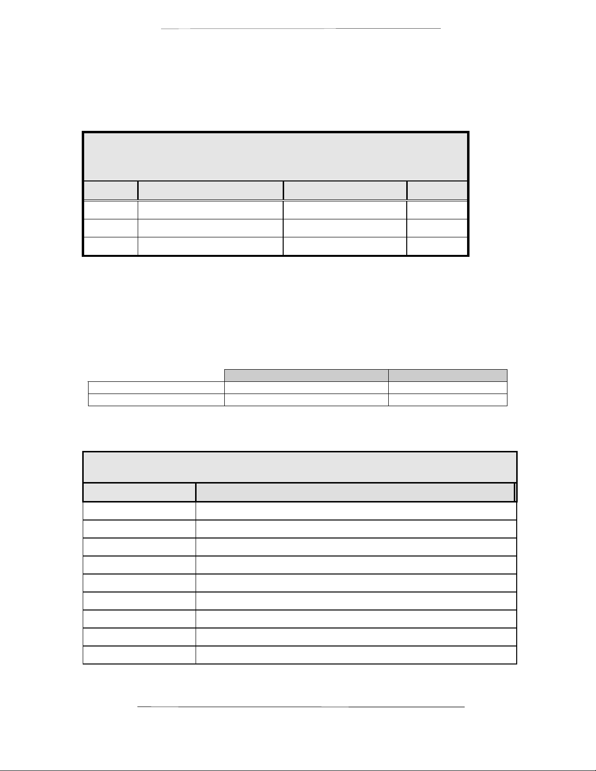
Revision
Level
1.0 9-10-99 Initial Release
Date Reason for Change
TM082 - Rev. 1.0 iv
Page 7

Page 8

RCF6001 Satellite Terminal Table of Contents
TM082 - Rev. 1.0 iv
Page 9

RCF6001 Satellite Terminal Description
Section One – RCF6001 Satellite Terminal Description
1.0 Introduction
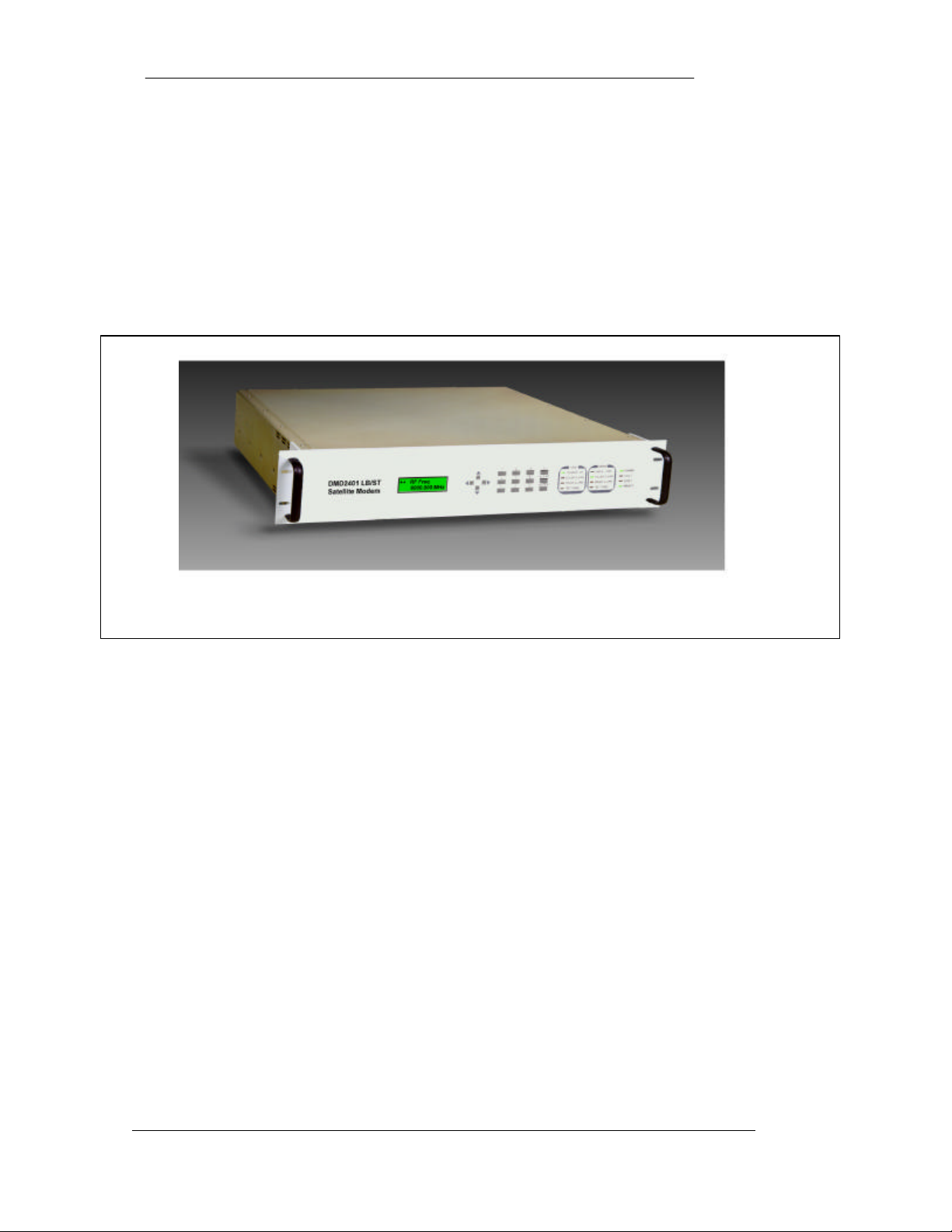
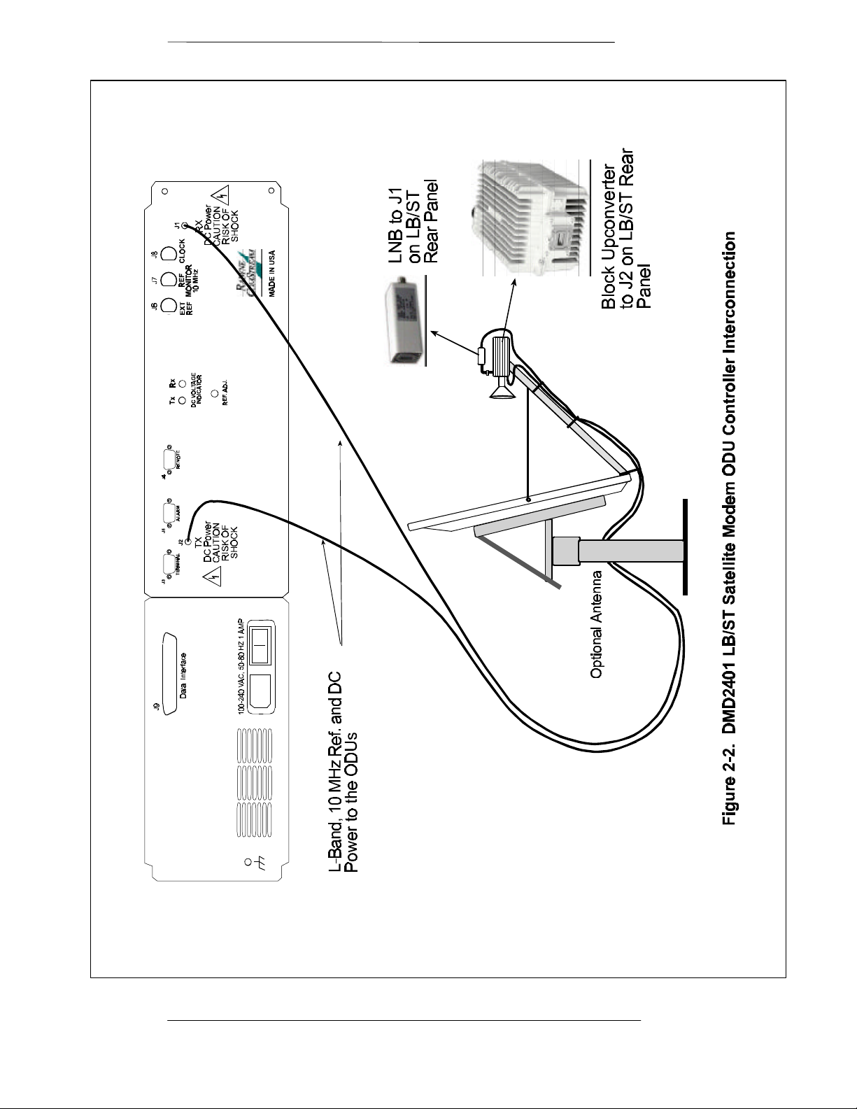
The RCF6001 is a C- or Ku-Band Satellite Terminal that consists of a Radyne ComStream DMD2401LBST
Satellite Modem, Block Upconverter (BUC) and Low Noise Block (LNB). The system is available in a
variety of frequencies and power levels. Cabling and
antennas can also be supplied for a single source
solution.
The frequency agile DMD2401 LBST is the heart of the
RCF6001 system. The DMD2401LBST modem supplies
an L-Band output frequency of 950-1525 MHz.
The modem also supplies power and a high stability 10
MHz reference signal through the center conductor of
the transmit and receive cables. This design eliminates
the use of an outdoor power supply and diplexer. The
LBST controls all parameters of the outdoor units
remotely or via the front panel of the modem. The
modulator and demodulator operate independently
using BPSK and QPSK modulation in either SCPC or
VSAT modes.
• Complete C- or Ku-Band Satellite Terminal
System
• Optional Antennas and Cabling
• Modem with Power and High-Stability
Reference (10 MHz) to Outdoor RF Units
• BPSK and QPSK Operation
• 9.6 to 4375 Kbps Operation
Highlights
The Block Upconverter (BUC) comes in a variety of frequencies and power levels. The BUC is based on a
simple block conversion with an L-Band input and a C- or Ku-Band output. A single LO does the
conversion from L-Band to the desired output frequency. The output power levels that are available for CBand BUCs are 5, 10, 20 and 40 watts. The available power levels for the Ku-Band BUCs are 2, 4, 8, 16
and 25 watts.
The Low Noise Block (LNB) comes in a variety of frequencies and power levels. The Low Noise Block does
a single LO conversion from C- or Ku-Band to an L-Band output. Typical gain of an LNB is 60 dB.
2.0 DMD2401 LB/ST Satellite Modem
The Radyne Corporation DMD2401 LB/ST L-Band Satellite Modem and Outdoor Unit (ODU) Driver is a
microprocessor-controlled Binary Phase Shift Keyed (BPSK) or Quadrature Phase Shift Keyed (QPSK),
Modulator and Demodulator for use as part of the transmitting and receiving ground equipment in a
satellite communications system. The DMD2401 LB/ST has the capability of delivering power and a 10
MHz Reference signal to a Low Noise Block Downconverter (LNB) and also to a Block Upconverter (BUC)
capable of an 8-Watt output. The DMD2401 LB/ST Modem is referred to as the “modem” or DMD2401
throughout the remainder of this document.
This versatile equipment package combines unsurpassed performance with numerous user-friendly front
panel programmable functions. All of the configuration, monitor and control functions are available at the
front panel. Operating parameters such as variable data rates, FEC code rate and IF/RF frequencies can
be readily set and reconfigured from the front panel by earth station operations personnel. Additionally, all
functions can be accessed with a terminal or personal computer via a serial link for complete remote
monitor and control capability.
TM082 - Rev. 1.0 Page 1-1
Page 10
Description RCF6001 Satellite Terminal
The DMD2401 LB/ST operates at data rates up to 4.375 Mbps. Selection of any data rate is provided over
the range of 9.6 Kbps to 4.375 Mbps in 1 bps steps.
The DMD2401 LB/ST is designed to perform as both ends of a satellite Single Channel Per Carrier (SCPC)
link or as the VSAT remote site modem in a TDMA hub system. The Modulator and Demodulator operate
independently using BPSK or QPSK modulation in either SCPC or VSAT modes.
The DMD2401 LB/ST is programmable from the front panel. The program menu was specifically designed
for ease of use to quickly put the modem online and for any network changes. The modem also can be
monitored and controlled through the RS485 or RS232 serial control channel.
Figure 1-1. DMD2401 LB/ST Satellite Modem Front Panel
Available options for the DMD2401 LB/ST include a low data rate asynchronous serial overhead channel
for remote monitor and control. Additionally, a Reed-Solomon codec is available for applications requiring
Bit Error Rates of 10
-10
.
1.1 Applications
Following are just a few representative forms of satellite communications links and networks in which the
DMD2401 LB/ST modem may be used.
1.1.1 SCPC Point-to-Point Links
The most straightforward application for a satellite modem is to serve as the Data Communications
Equipment (DCE) for a point-to-point data link. When used in this mode, two modems located at two
different sites are tuned to complementary transmit and receive frequencies. Each direction of the
communications link may have the same or entirely different transmission parameters. In this application, it
is typical that the link is established and maintained on a continuous basis, although a special “on demand”
case is described later.
1.1.2 SCPC Point to Multi–Point Links in a Broadcast Application
A broadcast application might involve the necessity of sending continuous or intermittent data from one
source and “broadcasting” the information to many remote locations. For instance, constant pricing
information and updates may be sent by a central location to many store locations. There may be minor
return information from the remotes acknowledging receipt.
Another broadcast application could be transmitting background music from a central location to many
store sites. In this case, there would be no return path.
Page 1-2 TM082 - Rev. 1.0
Page 11

RCF6001 Satellite Terminal Description
The topology of the network in both of these broadcast examples would typically be called a “Star” network.
As shown in the Figure below, the shape of the configuration is drawn with the central “Hub” as the center
of the star and the remotes as points of the star. In both cases the transmit frequency and other parameters
are shared by the receiver of all the remotes.
Star Network Configuration
Remote
B
Remote
Remote
C
A
Hub
Remote
E Remote
D
1.1.3 DAMA (Demand Assigned Multiple Access)
Suppose that we wanted to simulate a telephone network with a virtual switch between modems carrying
digitized voice information. We might use a central computer to assign a pair of frequencies for any
conversation and send this connection information to the proper sites to set up the connection. In this
application a new network configuration is usable. That is a “Mesh” network where any of the voice
modems at any site can be programmed to link with any other modem. The resulting link diagram looks
like a mesh of interconnects.
Since the frequencies can be assigned on demand, the network is then called “Demand Assigned, Multiple
1.1.4 TDMA (Time Division Multiple Access) Remote Site Application
In a TDMA network, the central Hub continually transmits a stream of outbound data containing information
for multiple remote sites, while the remote sites transmit back to the Hub on a timed basis. Each of these
remotes is said to “burst” its information back on a specific frequency. This may be the same inbound
frequency for all sites. Each of the remotes is responsible for accessing its own information from the
outbound data stream by reading the address assigned to specific parts of the data. The TDMA network
usually looks like the Star network shown above.
TM082 - Rev. 1.0
Page 1-3
Page 12

Page 13

RCF6001 Satellite Terminal Installation
Section 2 - Installation
2.0 Installation Requirements
The DMD2401 LB/ST Modem is designed to be installed within any standard 19-inch wide equipment
cabinet or rack, and requires 2 rack units of mounting space (3.5 inches) vertically and 21-inches of
depth. Including cabling, a minimum of 23-inches of rack depth is required. The rear panel of the
DMD2401LB/ST is designed to have power enter from the left and IF cabling enter from the center when
viewed from the rear of the modem. Data and control cabling can enter from either side although they
are closer to the right. The unit can be placed on a table or suitable surface if required.
There are no user-serviceable parts or configuration settings located inside the DMD2401 LB/ST
chassis. There is a potential shock hazard internally at the power supply module. DO NOT open
the modem case.
⇒⇒ CAUTION: Before initially applying power to the modem, it is a good idea to disconnect the
transmit output from the operating satellite ground station equipment. This is especially true if the
current modem configuration settings are unknown, where incorrect setting could disrupt existing
communications traffic.
2.1 Unpacking
The DMD2401 LB/ST was carefully packaged to avoid damage and should arrive complete with the
following items for proper installation:
1. DMD2401 LB/ST Modem Unit.
2. Power Cord, 6-foot with applicable AC connector.
3. Installation and Operation Manual.
2.1.1 Removal and Assembly
If using a knife or cutting blade to open the carton, exercise caution to ensure that the blade does not
extend into the carton, but only cuts the tape holding the carton closed. Carefully unpack the unit and
ensure that all of the above items are in the carton. If the Prime AC power available at the installation
site requires a different power cord/AC connector, then arrangements to receive the proper device will
be necessary before proceeding with the installation.
The DMD2401 LB/ST unit is shipped fully-assembled and does not require removal of the covers for any
purpose in installation. Should the power cable AC connector be of the wrong type for the installation,
either the cable or the power connector end should be replaced. The power supply itself is designed for
universal application using from 100 to 240 Vac, 50-60 Hz, 1.0 A.
2.2 Mounting Considerations
When mounted in an equipment rack, adequate ventilation must be provided. The ambient temperature
in the rack should preferably be between 10° and 35° C, and held constant for best equipment operation.
The air available to the rack should be clean and relatively dry. Modem units should not be placed
immediately above a high heat or EMF generator to ensure the output signal integrity and proper receive
operation.
TM082 - Rev. 1 Page 2-1
Page 14
Installation RCF6001 Satellite Terminal
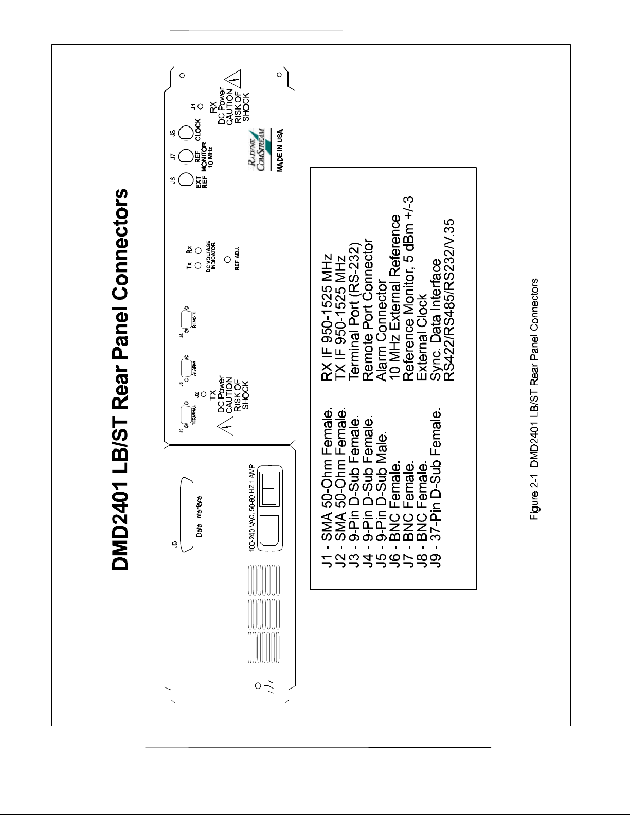
Table 2-1. DMD2401 LB/ST Rear Panel Connectors
Connector ID Description Function
J1 SMA 50-Ohm Female Rx IF 950-1525 MHz
J2 SMA 50-Ohm Female Tx IF 950-1525 MHz
J3 9-pin D-Sub Female RS-232 Terminal Port
J4 9-pin D-Sub Female Remote Port Connector
J5 9-Pin D-Sub Male Alarm Connector
J6 BNC Female 10 MHz External Reference
J7 BNC Female
J8 BNC Female External Clock
J9 37-Pin D-Sub Female Sync. Data Interface,
Do not mount the DMD2401 LB/ST in an unprotected outdoor location where there is direct contact with
rain, snow, wind or sun. The modem is designed for indoor applications only. The only tools required for
rack mounting the DMD2401 LB/ST is a set of four rack mounting screws and an appropriate
screwdriver. Rack mounting brackets are an integral part of the cast front bezel of the unit and are not
removable.
Reference Monitor, 5 dBm ± 3
RS422/RS485/RS232/V.35
J1 and J2, Tx and Rx IF connectors have voltage on the ports. Exercise care when the DMD2401
LB/ST has power applied.
2.4 Modem Connections / Interface Connectors
All modem connections are made to the labeled connectors located on the rear of the unit. The
connector definitions and pinout tables are shown below, and are those on the modem unit. Any
connection interfacing to the modem must be the appropriate mating connector.
NOTE: Shielded cables with the shield terminated to conductive backshells are required in order to meet
EMC directives. Cables with insulation flammability ratings of 94 VO or better are required for Low
Voltage Directives.
2.4.1 DMD2401 LB/ST Connector Pinout Tables
The following tables contain the pinout information for the various Data/IF connectors located on the rear
panel of the DMD2401 LB/ST. See Figure 2-1 for the DMD2401 LB/ST Rear Panel.
Page 2-2 TM082 - Rev. 1.0
Page 15
RCF6001 Satellite Terminal Installation
TM082 - Rev. 1.0
Page 2-3
Page 16
Installation RCF6001 Satellite Terminal
Page 2-4 TM082 - Rev. 1.0
Page 17
RCF6001 Satellite Terminal Installation
J3 – RS232 Terminal Port
Table 2-2.
J3 - RS232 Terminal Port - 9-Pin Female ‘D’
Pin No. Signal Description Direction
3 TxD Transmit Data Output
2 RxD Receive Data Input
5 Gnd Ground -----
J5 – Alarm Connection
The modem has two form-C dry contact alarm relays onboard and an alarm connector located on the
rear panel, the 9-pin male “D” sub connector J6.
The two relays are designated Modulator Alarm and Demodulator Alarm. Non-Alarm is defined as the
powered state of the relay. Thus, if there is a Modulator Alarm and/or Demodulator Alarm, the pins will
be connected as follows:
Alarm No Alarm
Modulator
Demodulator
Pins 2 and 3 Shorted Pins 1 and 2 Shorted
Pins 8 and 9 Shorted Pin 7 and 8 Shorted
The pin definitions for J5 are shown in Table 2-3 below. Note that the NC and NO (Normally Closed
and Normally Open) nomenclature applies to non-energized relays.
Table 2–3.
J5 - Alarm Connector – 9-Pin Male ‘D’ Sub Connector
J6 Pin Number Connection
1 Mod Alarm Relay A NO on Alarm
2 Mod Alarm Relay A Common
3 Mod Alarm Relay A NC on Alarm
4 ----5 AGC Voltage Output
6 Gnd
TM082 - Rev. 1.0
7 Demod Alarm Relay B NO on Alarm
8 Demod Alarm Relay B Common
9 Demod Alarm Relay B NC on Alarm
Page 2-5
Page 18

Installation RCF6001 Satellite Terminal
J4 - Remote
The RS-485 connection is for remote monitor and control of the modem.
Refer to Table 2-4 below for the pinouts.
Table 2-4.
J4- RS485 Remote Port - 9-Pin Female ‘D’
Pin No. Signal Description Direction
1 RS485 TxD-B Transmit Data B Output
2 TxC-A Transmit Clock A Output
3 TxC-B Transmit Clock B Output
4 RxC-A Receive Clock A Input
5 Common Signal Common
6 RS485 TxD-A Transmit Data A Output
7 RxC-B Receive Clock B Input
8 RS485 RxD-B Receive Data B Input
9 RS485 RxD-A Receive Data A Input
J9 – Data Interface
Table 2–5.
J9 - Sync Data RS422/RS485/RS232/V.35 - 37-Pin Female
Pin Number Signal Description Direction
4 SD-A Send Data A (-) Input
22 SD-B Send Data B (+) Input
5 ST-A Send Timing A (-) Output
23 ST-B Send Timing B (+) Output
6 RD-A Receive Data A (-) Output
24 RD-B Receive Data B (+) Output
7 RS-A Request to Send A (-) Input
25 RS-B Request to Send B (+) Input
8 RT-A Receive Timing A (-) Output
26 RT-B Receive Timing B (+) Output
9 CS-A Clear to Send A (-) Output
14 MF Mod Fault - Open
Output
Collector
Page 2-6 TM082 - Rev. 1.0
Page 19

RCF6001 Satellite Terminal Installation
33 DF Demod Fault - Open
Collector
27 CS-B Clear to Send B (+) Output
11* DM-A Data Mode A (-) Output
29* DM-B Data Mode B (+) Output
13 RR-A Receiver Ready A (-) Output
31 RR-B Receiver Ready B (+) Output
3 BAL EXC-AExternal Clock A (-) Input
21 BAL EXC-BExternal Clock B (+) Input
16 RX-0-A Receive Octet A (-) Output
34 RX-0 B Receive Octet B (+) Output
17 TT-A Terminal Timing A (-) Input
35 TT-B Terminal Timing B (+) Input
1, 19, 20, 37 GND Signal Ground
Output
*NOTE: The DMD2401 Satellite Modem has the capability of constantly outputting the DM/DSR
signal. (DSR and DM are actually the same signal). The modem is always in the condition of
being able to pass data. DTR input to the modem is not necessary. The DM/DSR output of the
modem is located on pins 11 and 29 as shown above.
J6 – Ext. Ref. IN
This port is used for injecting an External Reference Frequency into the modem. The DMD2401
master oscillator is locked to this source. All internally generated frequencies within the modem
will attain the stability of the applied external reference. The external reference must meet the
following parameters:
Frequency: 256 KHz to 10 MHz in multiples of 8 KHz
Amplitude: 0.2 V p-p to 5 V p-p
Type: Sinewave or Squarewave
TM082 - Rev. 1.0
Page 2-7
Page 20

Page 21

RCF6001 Satellite Terminal Maintenance
Section 3 – RCF6001 Satellite Terminal Operation
3.0 Operating Procedures
Operation of the DMD2401 LB/ST consists of controlling the unit operating parameters and monitoring
status and responses via front panel or Terminal Mode control.
These methods may be used separately or together to monitor and control the DMD2401 LB/ST.
3.1 Front Panel Control
The front panel of the DMD2401 allows complete monitor and control of all modem parameters and
functions via a keypad, LCD display and status LEDs.
3.1.1 Front Panel Layout and Features
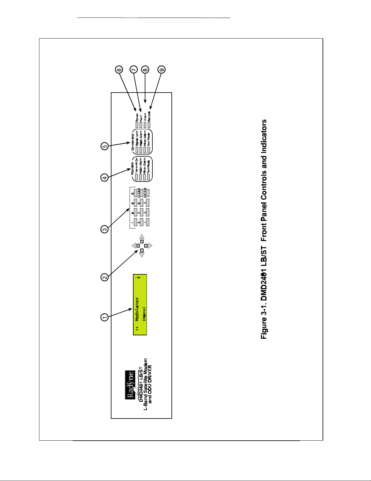
The front panel layout is shown in Figure 3–1, showing the location and labeling of the front panel. The
front panel is divided into three functional areas: the LCD display, the Keypad and the LED Indicators,
each described below.
3.1.2 Front Panel LCD Display
The front panel display is a 2 line by 16 character LCD display. The display is lighted and the brightness
can be set to increase when the front panel is currently in use. The LCD display automatically dims after
a period of inactivity. The display has three distinct areas showing current information. The upper left
shows the current area of use, either Mod, Demod, Modem or Test. The upper right shows the current
parameter being monitored, such as ‘Freq.’ (frequency) or ‘Bit Rate.’ The lower line shows the current
value of that parameter. The LCD display is a single entry window into the large matrix of parameters
that can be monitored and set from the front panel.
The backlight brightness can be set for two states: Active and Idle. The active state is entered whenever
a key on the front panel is depressed, while the idle state occurs after approximately 45 seconds of
inactivity. Each state may be set to ‘Off’, 1/3 brightness, 2/3 brightness and full brightness. The default
setting is full in the active state and 1/3 in the idle state. To change the settings for either state, go to the
‘Modem LCD Active’ or ‘Modem LCD Idle’ brightness parameter and adjust to the desired values.
3.1.3 Front Panel Keypad
The front panel keypad consists of two areas: a 10-key numeric entry with 2 additional keys for the
‘Enter’ and ‘Clear’ function. The second area is a set of ‘Arrow’ or ‘Cursor’ keys (↑↑), (↓↓), (→→), (←←), used
to navigate the parameter currently being monitored or controlled. During entry, the cursor keys allow
moving a cursor to individual digits of a numerical entry or scrolling through the available options of a
selection entry.
TM082 - Rev. 1.0 Page 4-1
Page 22
Maintenance RCF6001 Satellite Terminal
Page 4-2 TM082 - Rev. 1.0
Page 23
RCF6001 Satellite Terminal Maintenance
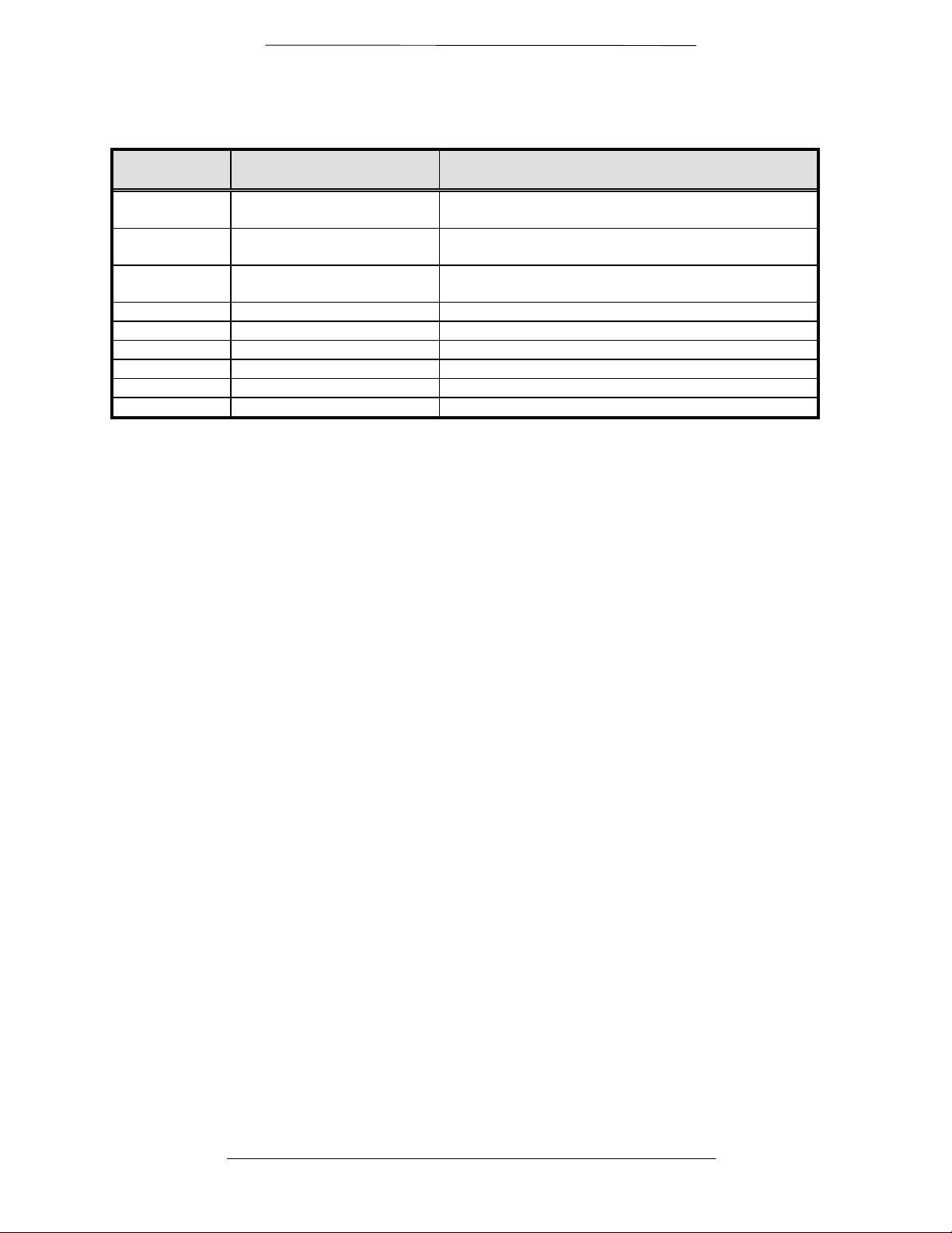
Table 3-1. Front Panel Controls and Indicators
Figure 3-1
Description Function
Item Number
1 LCD Front Panel Display Displays Modem Operating parameters and
Configuration data
2 Cursor Control Arrows Controls the up, down, right and left motion of the
cursor in the LCD Display window
3 Numeric Keypad Allows entry of numeric data and Clear and Enter
function keys
4 Modulator LEDs See Below for Itemized descriptions of these LEDs
5 Demodulator LEDs See Below for Itemized descriptions of these LEDs
6 Power LED Indicates Modem is powered-up
7 Fault LED A fault has occurred; Common Fault
8 Event LED See Paragraph 3.5 for details
9 Remote LED Remote Control Operation in progress
3.1.4 Front Panel LED Indicators
There are 12 LEDs on the modem front panel to indicate status of the modem’s operation. They are
separated into three columns representing (from left to right) the Modulator status, the Demodulator
status and the Modem (Unit) status. The LED colors maintain a consistent meaning. Green signifies that
the indication is appropriate for normal operation, Yellow means that there is a condition not proper for
normal operation. Red indicates a fault condition that will result in lost communications.
Modem LED Indicators
1. Power: Green – Indicates the modem unit is currently under power.
2. Fault: Red – If summary fault condition exists from either Alarm A or B.
3. Stored Event: Yellow – Indicates that a condition or event has occurred that the
modem has stored in memory. The events may be viewed from the
Front Panel or in the Terminal mode.
4. Remote: Green – Indicates that the unit is set to respond to the remote control
input.
Modulator LED Indicators
1. Transmit On: Green – Indicates that the transmit output is currently active.
2. Major Alarm: Red – Indicates that the transmit direction has failed, losing traffic.
3. Minor Alarm: Yellow – Indicates a transmit warning condition exists.
4. Test Mode: Yellow – Indicates the modulator is involved in a current test mode
activity.
Demodulator LED Indicators
1. Signal Lock: Green – Indicates receiver lock to an incoming CXR and data
including FEC sync.
2. Major Alarm: Red – Indicates that the receive direction has failed, losing traffic.
3. Minor Alarm: Yellow – Indicates a receive warning condition exists, either an
incoming carrier with a low input level or a low Eb/No (programmable
threshold).
4. Test Mode: Yellow – Indicates the receiver is involved in a current test mode
activity.
3.1.4.1 Guide to Front Panel Monitor and Control
The front panel can be used to perform complete monitor and control of the modem setup and operating
parameters. The operation of the front panel becomes very easy after a short period of use in which the
user becomes familiar with the basic concepts and operations.
3.2 Modem Terminal Mode Control
The modem can be interactively monitored and controlled in the Terminal mode, with a full screen
presentation of current settings and status. Programming is accomplished by selecting the item to be
TM082 - Rev. 1.0 Page 4-3
Page 24

Maintenance RCF6001 Satellite Terminal
modified and pressing the terminal key of the option number. For example, to change the transmit data
rate, enter ‘33’ at the terminal. The modem will respond by presenting the options available and
requesting input. Two types of input may be requested. If the input is multiple choice, the desired choice
is selected by pressing the ‘Space’ key. When the desired option is displayed, press the ‘Enter’ key to
select that option. The other possible input type requires a numerical input (such as entering a frequency
or data rate). This type of input is followed by pressing the ‘Enter’ or carriage return key. An input can be
. Invalid input keys cause an error message to be displayed
on the terminal.
The Terminal Control Mode supports serial baud rates of 2400, 9600 and 19200. The connection must
be set for 8 data bits, 1 stop bit and no parity (8,N,1). Three terminal emulations are supported: VT100,
WYSE 50, and ADDS. The emulation type can be changed either from the front panel or by pressing ‘$’
(dollar sign) on the terminal keyboard. The terminal menus are shown in Appendix C at the end of this
manual.
3.3 Modem Remote Port Control
The modem can be controlled by an external Monitor & Control (M&C) system through Remote Port
mode (also referred to as Computer Mode). Communication between the DMD2401 and the external
system control computer is via a binary protocol which is described in detail in Appendix B at the end of
this manual. The remote port provides RS485 capability and thus can be used with a multi-drop control
bus allowing a single external M&C computer to control several DMD2401 modems.
3.4 Parameter Setup
To set any parameter, the four arrow keys to the right of the LCD display are used to select the
parameter to be set, followed by pressing the ‘Enter’ key to indicate that a new entry is desired, then
setting the parameter via the numeric keypad and finalizing the data entry using the ‘Enter’ key. The
current input can be canceled by depressing the ‘Clear’ key at any time before pressing ‘Enter’. When
the entry involves selection of 1 of several choices, this is accomplished by either: pressing an option
number selection (0 to max. where max. may be 1 to 4) then pressing the ‘Enter’ key, or, using the up
and down arrow keys to scroll though the available options, pressing ‘Enter’ when the desired option is
displayed. When scrolling though the available options, the current setting is denoted by an arrow in the
left column position.
Following a valid input, the modem will place the new setting into the nonvolatile EEPROM making it
available immediately and also automatically the next time the unit is powered-up.
3.5 Modem Checkout
The following descriptions assume that the modem is installed in a suitable location with prime AC power
applied and supporting equipment available.
Page 4-4 TM082 - Rev. 1.0
Page 25
RCF6001 Satellite Terminal Maintenance
3.5.1 Initial Power-Up
⇒⇒ CAUTION: Before initial powerup of the DMD2401 LB/ST, it is a good idea to disconnect the
transmit output from the operating satellite ground station equipment. This is especially true if the
current modem configuration settings are unknown, where incorrect setting could disrupt existing
communications traffic. New modems from the factory are normally shipped in a default
configuration which includes setting the transmit carrier off.
Turn the unit ‘ON’ by placing the rear panel switch (above the power entry connector) to the ‘ON’
position. At initial and every subsequent power-up, the modem processor will test itself and several of its
components before beginning its main monitor/control program. These power-up diagnostics show no
results if successful. If a failure is detected, an Alarm LED will illuminate.
The initial field checkout of the modem can be accomplished from the front panel or in the Terminal
Mode. The Terminal Mode has the advantage of providing full screen access to all of the modem’s
parameters, but requires a separate terminal or computer running a terminal program. The unit is placed
into terminal mode by setting two options via the front panel. First set the ‘Modem – Remote’ parameter
to ‘Terminal’ (option 3), then set the ‘Modem – Remote Port’ parameter to ‘RS–232’ (option 0). The
‘Modem – Bit Rate, Format and Parity’ also requires setting to match the terminal setting. The Modem
Remote Address serves no function in the Terminal mode. Terminal Setup is as follows:
Terminal Setup:
Baud Rate: 19.2 K
Data Bits: 8
No Parity
1 stop bit
3.6 DMD2401 Automatic Uplink Power Control (AUPC) Operation
The DMD2401 modem has an optional built-in provision for Automatic Uplink Power Control (AUPC).
AUPC attempts to maintain a constant Eb/No at the receive end of an SCPC link. This is especially useful
when operating over a satellite at Ku-Band frequencies in locations with high rainfall periods.
Note: An Asynchronous or IBS Interface is required for AUPC. Also, IBS (Async) Framing Mode
MUST be selected to provide a channel for AUPC operation.
The IBS (Async) Framer Data Mode provides a service channel between the two sites of a link permitting
the modem processors to send messages and get responses over this channel. AUPC can be set to
operate on either or both directions of a link but always requires a bi–directional channel. Therefore,
both the Modulator and Demodulator interface mode must be set to IBS (Async) for the AUPC menus to
be visible and for the AUPC function to operate properly. The AUPC functions and their descriptions are
shown below:
Function Description
AUPC
Enables/Disables the AUPC to function locally
ENABLE/DISABLE
AUPC Eb/N
o
Desired Eb/N0 of remote modem
AUPC MIN LVL Sets minimum output power to be used
AUPC MAX LVL Sets maximum output power to be used
AUPC DEF LVL Sets default output power to be used
TM082 - Rev. 1.0 Page 4-5
Page 26

Maintenance RCF6001 Satellite Terminal
The AUPC menus are located under the Modulator Menu as shown schematically below:
(If Installed)
The basic AUPC operation is described as follows: Assume that the two modems, one at each end of the
link, are set to AUPC operation. Only one direction is discussed, but the same functions could be
occurring in both directions simultaneously. Modem “A” is transmitting to modem “B” under normal
conditions and modem “B” has a receive Eb/No of 7.5 dB. Modem “A” has been set to an AUPC Eb/No
on the front panel of 7.5 dB, and is currently outputting –15 dBm. Next, it begins raining at location “B”,
and the Eb/No drops to –7.0 then –6.8 dB. Modem “B” is constantly sending update messages to “A” and
reports the current Eb/No. When “A” sees the drop in Eb/No, it slowly begins to raise the output power,
and raises it again when it sees further drops. As the rain increases in intensity, and the Eb/No decreases
again, “A” continues to increase its power level to compensate, and when the rain diminishes and quits, it
also lowers its power level to compensate. The operation is therefore a feedback control loop with the
added complication of a significant time delay.
There are safeguards built into the AUPC system. First, the Modulator has two additional parameters that
allow control of the maximum and minimum power output level. Second, a default power level is
specified which takes precedence over the output power level during signal loss or loss of AUPC channel
communication. The default power level should normally be set to a high enough level to reestablish
communication regardless of rain fade. The other controls are built into the operating control software to
limit response times and detect adverse operating conditions.
3.7 DMD2401 Asynchronous Overhead Operation
3.7.1 Asynchronous Framing/Multiplexer Capability
The Asynchronous Framing/Multiplexer is capable of multiplexing a relatively low-speed overhead
channel onto the terrestrial data stream resulting in a slightly higher combined or aggregate data rate
through the modem. The overhead channel is recovered at the far end. This added channel is termed
variously an overhead channel, service channel, async channel or in IESS terminology an ES to ES data
Page 4-6 TM082 - Rev. 1.0
Page 27

RCF6001 Satellite Terminal Maintenance
channel. The basic frame structure used by the multiplexer is that specified in the IESS-309 standard,
Page 60, Figure 10, resulting in a 16/15 aggregate to through data ratio.
KBPS BAUD
9.6 300
19.2 600
32 600
64 1200
128 2400
192 4800
256 4800
320 9600
384 9600
448 9600
512 9600
576 9600
640 19200
704 19200
768 19200
832 19200
896 19200
960 19200
1024 19200
1088 19200
1152 19200
1216 19200
1280 19200
1344 19200
1408 19200
1472 19200
1536 19200
1600 19200
1664 19200
1728 19200
1792 19200
1856 19200
1920 19200
1984 19200
2048 19200
Two software controlled modes are designed into the card to best utilize the available bits; “Standard
. The characteristics of the channel interface is also determined by the standard or
Async mode.
The Async Channel can be set under software-control to either RS-232 or RS-485 mode. The pin
assignments for both modes are shown in Table 1. The “RS-485” setting controls the output into tri-state
when the modem is not transmitting data, allowing multiple modem outputs to be connected together.
3.8 Standard IBS Mode
In the first or "Normal" mode, all bit assignments are per the IBS standard. The bits of Overhead
Housekeeping byte 32 are implemented as shown below:
TM082 - Rev. 1.0 Page 4-7
Page 28

Maintenance RCF6001 Satellite Terminal
Bit 1 - ES to ES Data Channel This bit is routed directly to the ES to ES Data Channel. Its data
rate is 1/512th of the aggregate rate (or 1/480th of the through
terrestrial data rate), and is normally used to super-sample an
asynchronous data channel.
Bit 2 - Part of the Frame Alignment word.
Bit 3 - Backward Alarm Transmit and Receive with main processor to activate main
alarm/LED
Bit 4 - Multiframe Message As per IBS
Bits 5 and 6 - Spare Not currently utilized
Bits 7 and 8 - Encryption Utilization Not currently utilized
The ratio of the through terrestrial data channel rate to the aggregate rate is 15/16.
The standard transmit and receive channels of the ES to ES data channel in standard IBS mode are raw
channels operating at the specific bit rate as controlled by the data channel rate, without buffering. Also,
no clocks are provided with this channel. Since it would be rare that the data rate provided was exactly
that required for a standard rate device, the only method of communicating using this channel is to allow
it to super-sample the user data.
3.9 Asynchronous Multiplexer Mode
Since many of the frame bits in the standard IBS mode are not used, an "Enhanced" multiplexer mode
has been implemented that can be engaged under software control. Since this mode changes the use of
many of the framed non-data bits, this mode is only usable when the DMD2401 is at both ends of a link.
In this mode, the overhead signaling bytes 16 and 48 can be used to implement a significantly higher
speed ES to ES Data Channel under software control. When implemented, this rate is 16 times that of
the normal IBS standard, or 1/30th of the terrestrial data rate (1/32nd of the aggregate rate).
NOTE: The IBS (Async) mode MUST be selected for true Asynchronous channel operation to be available.
Page 4-8 TM082 - Rev. 1.0
Page 29

RCF6001 Satellite Terminal Maintenance
TM082 - Rev. 1.0 Page 4-9
Page 30

Maintenance RCF6001 Satellite Terminal
3.10 Front Panel Menu Selections
Page 4-10 TM082 - Rev. 1.0
Page 31

RCF6001 Satellite Terminal Maintenance
The front panel has seven top level menus as follows: Modulator, Demodulator, Interface, Monitor,
Alarms, System, and Test. The menu items are shown in the tables below:
The following table is a listing of the Command and Status parameters available to the user from the
front panel of the DMD2401 LB/ST. A brief description of each of the items follows. By using the
following descriptions and the previous Figures, the user should become familiar rather quickly with the
hierarchical structure of the DMD2401 LB/ST command and status parameters available at the front
panel of the modem.
Modulator
Mod IF/RF
NOTE: The LO frequencies of the Block Upconverter (BUC) and LNB must be entered first under
the ‘System/General/BUC LO/LNB LO’ menus. The LB/ST will then calculate the Mod and Demod
IF/RF frequencies.
Tx RF
This Frequency is precalculated by the LB/ST after the operator has
entered the LO frequencies of the BUC and LNB under the
System/General menu.
Tx IF
Enter in 1 MHz steps from 950-1525 MHz.
Power
Tx Power level is entered in dBm from -5 to -30 dBm.
Carrier
Turns carrier On & Off
Spectrum Inv
Inverts the direction of rotation for PSK modulation.
Normal meets the IESS specification
Modulation
Sets modulation type QPSK, BPSK, OQPSK
Mod Data
Data Rate
Sets Data Rate in BPS Steps. Use arrows or Keypad.
Conv Enc
Selects Tx code rate and type
Diff Encode
Enables or disables differential encoder
Scrmbl Sel
Selects scrambler type (V.35-IESS)
Scrmbl Ctrl
Enables or disables scrambler operation
Data Invert
Sets data polarity to Normal, Inverted, or Auto.
Reed-Solomon
Enable/Disable the Reed-Solomon Encoder
ModRS Codes
Displays the currently used n, k Reed-Solomon Codes. Custom RS
codes may be selected.
ModRS Depth
Displays the currently used Reed-Solomon interleaver depth. In Closed
Net Mode, Depth = 8 or 4 may be selected.
Demodulator
Demod IF/RF
TM082 - Rev. 1.0 Page 4-11
Page 32

Maintenance RCF6001 Satellite Terminal
NOTE: The frequencies of the Block Upconverter (BUC) and LNB must be entered first under the
‘System/General’ menu. The LB/ST will then calculate the Mod and Demod IF/RF frequencies.
Tx RF
This Frequency is precalculated by the LB/ST after the operator has
entered the frequencies of the BUC and LNB under the System/General
menu.
Tx IF
Enter in 1 MHz steps from 950-1525 MHz
Spectrum Inv
Inverts the direction of rotation for PSK modulation in demod.
Normal meets the IESS specification
Demodulation
Sets Demodulation type QPSK, BPSK, OQPSK
Swp Bound
Sets acquisition range for the demodulator
Input Limit
Demod Data
Data Rate
Sets Data Rate in BPS Steps. Use arrows or Keypad
Conv Dec
Selects Rx code rate and type
Diff Decode
Enables or disables differential decoder
Dscrmbl Sel
Selects descrambler type
Dscrmbl Ctrl
Enables or disables descrambler operation
Data Invert
Sets data polarity to Normal, Inverted, or Auto.
Reed-Solomon
Interface
General
Intf Type
Tx Setup
Enable/Disable the Reed-Solomon Decoder
DMDRS Codes
Displays the currently used n, k Reed-Solomon Codes. In
Closed Net Mode, custom RS codes may be selected.
DMDRS Depth
Displays the currently used Reed-Solomon deinterleaver depth.
In Closed Net Mode, Depth = 8 or 4 may be selected.
EXT Clk Freq
Selects Frequency of External Clock.
Freq Ref Src
Selects Internal, External, or High Stability
Ext Ref Freq
Sets the External Reference Frequency
Selects Interface type, V.35/422/232
Tx Ckt ID
Provides entry of Tx circuit Identifier
Circuits can be given up to an 11 character alphanumeric identity
Tx Clock
SCT (Int)
Page 4-12 TM082 - Rev. 1.0
Page 33

RCF6001 Satellite Terminal Maintenance
Clk Polarity
Normal
SCT Source
Internal
Tx Terr Intf
RS422
Rx Setup
Rx Ckt ID
Provides entry of Rx circuit Identifier
Circuits can be given up to an 11 character alphanumeric Identity
such as DLINK1
Buff Size
Set the Doppler buffer size in Bytes
Buff Size
Sets Doppler buffer size in ms.
Buff Clk
Selects buffer clock source: SCTE (Ext)
Clk Polarity
Normal
Rx Terr Intf
RS422
Monitor
Level
Estimated receive signal level as seen by the Demodulator
Eb/No
Estimated Eb/No as seen by the Demodulator.
SER
Estimated channel error rate (before decoding) measured by the modem.
CBER
Estimated corrected bit error rate (after decoding).
Error Count
Current Error Count from the Viterbi Decoder.
Offset Freq
The received carrier frequency offset as measured by the modem.
Event Buff
History of events recorded in the event buffer. A maximum of 40 events may be
stored in the buffer. Upon receipt of the 41st event, the first received event is
automatically deleted, and so on, maintaining the maximum 40 events.
Press Clear to Erase Events
Voltages (Menu)
+5 Volt
Measured voltage of the +5 volt power bus inside modem.
+12 Volt
Measured voltage of the +12 volt power bus inside modem.
-12 Volt
Measured voltage of the -12 volt power bus inside modem.
Buffer Stat
Doppler buffer % full status.
Press Clr to Center Buffer
Causes Doppler buffer to re-center
BER Exponent
TM082 - Rev. 1.0 Page 4-13
Page 34

Maintenance RCF6001 Satellite Terminal
Sets the time base for the channel error rate measurement, used to
estimate Eb/No. This number is ‘N’ in the following equation: B=10N;
where: ‘B’ is the number of data bits in the averaging period.
Alarms
Modem Alarms
Active Alrms
Major Tx
TxuProc Mask
Tx Processor fault
Indicates a HW failure within the modem.
TxPower Mask
Indicates that the Modem Tx output power is within allowed
tolerance. A solid indication indicates a HW or programming
failure within the modem.
TxOSClk Mask
Indicates that the TX Oversample clock PLL is not locked. This
alarm will flash on during certain modem parameter changes. A
solid indication indicates a HW or programming failure within the
modem.
CompClk Mask
Indicates that Tx composite clock PLL is not locked.
This alarm will flash on during certain modem parameter
changes. A solid indication indicates a HW or programming
failure within the modem.
TxSynth Mask
Indicates that Tx IF synthesizer is not locked.
This alarm will flash on during certain modem parameter
changes.A solid indication indicates a HW or programming
failure within the modem.
FPGACfg Mask
REF PLL MASK
Pass/No
TxForce
Pass/No
Major Rx
RxuProc Mask
Rx Processor fault
Indicates a hardware failure within the modem.
SigLoss Mask
Indicates that the demod is unable to lock to a signal.
IF Synth Mask
Indicates the Rx IF synthesizer is not locked.
This alarm will flash ON during certain modem parameter
changes. A solid indication indicates a HW or programming
failure within the modem.
BuffPll Mask
RxLevel Mask
RxForce Mask
Page 4-14 TM082 - Rev. 1.0
Page 35

RCF6001 Satellite Terminal Maintenance
Minor Tx
Tx Activity
TerrClk Mask
Indicates no terrestrial clock activity.
IntClk Mask
Indicates no SCT clock activity.
BNCClk Mask
Indicates no BNC clock activity
TxSatCk Mask
Indicates no Tx Sat clock activity
Tx Data Mask
Indicates no Tx data activity.
TerrAIS Mask
Indicates that AIS has been detected in the Tx data
stream.
Minor Rx
BufUFLw Mask
Indicates that a Doppler buffer underflow has occurred.
BufOFLw Mask
Indicates that a Doppler buffer overflow has occurred.
Buf <10% Mask
Indicates that the Doppler buffer is about to underflow.
Buf >90% Mask
Indicates that the Doppler buffer is about to overflow.
VitLock Mask
Indicates that the Viterbi decoder is not locked.
SequLock
Indicates that the Sequential decoder is not locked.
Rx Activity
Buf Clk Mask
Indicates that the selected buffer clock source is not
active.
Ext BNC Mask
Rx Sat Mask
Indicates that the Rx Sat buffer clock source is not
active.
ExtRef Mask
SatAIS Mask
Indicates that AIS has been detected in the Rx data
stream.
Rx RS Faults
Dec Lock
Indicates status of the Reed-Solomon Decoder
Lock
Dintlvr
Indicates status of the Reed-Solomon deinterleaver word fault
UnCWord
Indicates status of the Reed-Solomon uncoded
word fault
Common
-12 Power
Indicates power supply voltage out of range.
+12 Power
Indicates power supply voltage out of range.
TM082 - Rev. 1.0 Page 4-15
Page 36

Maintenance RCF6001 Satellite Terminal
+5 Power
Indicates power supply voltage out of range.
Battery
Indicates battery failure
RAM/ROM
Indicates M&C memory fault.
M&C uProc
Indicates M&C microprocessor HW failure.
Ref PLL Mask
Pass/No
Ext EXC Mask
Pass/No
Ext Ref Mask
Indicates no activity on the external reference.
HS Ref Mask
Pass/No
HSRFPLL Mask
Pass/No
Latched Alrm
The following alarms are latched in order to catch intermittent failures:
Major Tx
Major Rx
Minor Tx
Minor Rx
Common
TxµProc
TxPower
TxOSClk
CompClk
TxSynth
FPGACfg
RxuProc
Sigloss
IFSynth
BuffPLL
RxLevel
Tx Activity
RS FIFO
TxBUC
BufUFlw
BufOFLw
Buf < 10%
Buf > 90%
Viterbi
Seq Lock
Rx Activity
Buf Clk Mask
Ext BNC Mask
Rx Sat Mask
ExtRef Mask
SatAIS Mask
-12 Power
Page 4-16 TM082 - Rev. 1.0
Page 37

RCF6001 Satellite Terminal Maintenance
+12 Power
+5 Power
Battery
RAM/ROM
M&C uProc
Ref PLL
Ext Ref Lock
Ext EXC Act
HS Ref Mask
HSRFPLL
System
Control Mode
Selects active control source between Front Panel, Terminal and Computer
General
Date
Time
Backlight
Level
Sets backlight level for ON condition.
Timeout
Sets number of seconds (0..99) from keyboard inactivity to
backlight turn off.
Key Click
Enable/Disable front panel audible key click.
Radyne DMD2401 LB/ST Version 2.0
Modem Version
Firmware Rev (Menu)
FPGA
Tx CPLD
Rx CPLD
NOTE: Enter LO frequencies in MHz before entering the Mod and Demod IF Frequencies.
BUC LO (MHz)
Enter frequency in MHz
BUC LO Loc.
Low Side
LNB LO (MHz)
Enter frequency ijn MHz
LNB LO Loc.
Low Side
M&C
Term Baud
M&C Remote Port Baud Rate
Emulation
Terminal Emulation mode: Selects Terminal Emulation Mode for
Terminal Port, VT100, ADDS-VP, WYSE 50
Remote Mode
Remote Emulation mode: Selects Remote Port Protocols
Remote Address
Remote Baud
Test
2047 Test Tx/Rx
Enables the 2047 pattern test
TM082 - Rev. 1.0 Page 4-17
Page 38

Maintenance RCF6001 Satellite Terminal
Tx enables the TX pattern generator
Rx enables the receive pattern checker
Tx/Rx enables both
Tx Insert Errors
Selects the number of errors to insert
Once the number of errors to insert has been selected, pushing ‘enter’ twice
causes the number of errors selected to be inserted in the data stream.
Rx 2047 Err
Shows the number of errors detected by the 2047 pattern checker.
Rx 2047 BER
Shows the number of errors detected by the 2047 pattern checker.
Clear 2047 (Ent=Y, Clr=N)
Loopbacks
Carrier
Normal
Tx Force Alarm
Rx Force Alarm
Remote Port
LED Test Normal
Page 4-18 TM082 - Rev. 1.0
Page 39

RCF6001 Satellite Terminal Maintenance
Section 4 - Maintenance
4.0 Periodic Maintenance
The DMD2401 LB/ST L-Band satellite modem requires no periodic field maintenance procedures. The unit
contains very few adjustments and most calibration is digital and held in EEPROM. Should a unit be
suspected of a defect in field operations after all interface signals are verified, the proper procedure is to
replace the unit with another known working modem. If this does not cure the problem, faulty wiring,
cabling or power should be suspected.
There is no external fuse on the DMD2401 LB/ST modem. The fuse is located on the power supply
assembly inside the case, and replacement is not intended in the field.
4.1 2401 LB/ST Troubleshooting
The following is a brief list of possible problems that could be caused by failures of the modem or by
improper setup and configuration for the type of service. The list is arranged by possible symptoms
exhibited by the modem.
Symptom: The Modem will not acquire the incoming carrier:
Possible Cause: Improper receive input to modem.
Action: Check that the receive cabling is correct.
Possible Cause: Receive carrier level too low.
Action: Check that the receive cabling is correct, that the downconverter is properly set and that the
LNA is turned on. If a spectrum analyzer is available, locate and measure the receive level, which should
not be below -55 dBm absolute.
Possible Cause: Receive carrier frequency outside of acquisition range.
Action: Check that the receive acquisition range is adequate for the possible system offsets. Setting the
value to 30 KHz is a standard value encompassing all normal offsets. After acquisition, the actual
receive frequency can be read from the front panel.
Possible Cause: Transmit carrier incompatible.
Action: Check the receive parameter settings and ensure that they match those on the modulator.
Possible Cause: Modem is in test mode.
Action: Check the modem front panel for yellow warning LEDs indicating a test mode is enabled. Self-
Test or RF Loopback disconnects the Demodulator from the IF receive input connector.
4.2 DMD2401 LB/ST Fault Philosophy
The DMD2401LB/ST performs a high degree of self-monitoring and fault isolation. The alarms are
separated into three categories; Active Alarms, Common Equipment Alarms, and Latched Alarms. Also,
a feature exists that allows the user to ‘Mask’ out certain Alarms as explained below.
4.2.1 Alarm Masks
The user has the capability to ‘Mask’ individual alarms on the DMD2401. When an Alarm is masked, the
front panel LEDs and the Fault Relays do not get asserted, but the Alarm will still be displayed. This
feature is very helpful during debugging or to lock out a failure that the user is already aware of.
4.2.2 Active Alarms
TM082 - Rev. 1.0 Page 4-19
Page 40

Maintenance RCF6001 Satellite Terminal
4.2.2.1 Major Alarms
Major alarms indicate a modem hardware failure. Major alarms may flash briefly during modem
configuration changes and during power-up but should not stay illuminated.
Alarms are grouped into Transmit alarms and Receive alarms - Transmit and Receive are completely
independent.
4.2.2.2 Minor Alarms
Minor alarms indicate that a problem may persist outside the modem such as loss of terrestrial clock,
loss of terrestrial data activity, or a detected transmit or receive AIS condition. Alarms are grouped into
Transmit Alarms and Receive Alarms - Transmit and Receive are completely independent.
4.2.2.3 Latched Alarms
Latched alarms are used to catch intermittent failures. If a fault occurs, the fault indication will be latched
even if the alarm goes away. After the modem is configured and running, it is recommended that the
latched alarms be cleared as a final step.
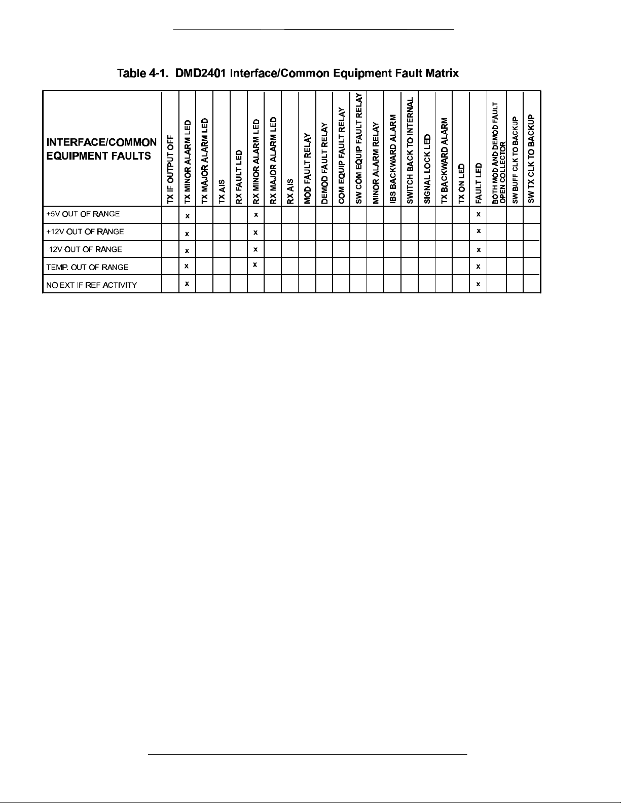
4.3 DMD2401 Fault Tree Matrices
Tables 4-1 through 4-3 represent, in matrix form, the faults that may occur within the DMD2401. There
are three matrices; Tx Faults, Rx Faults, and Common Equipment Faults.
4.3.1 Interpreting the Matrices
The first vertical column in the Tables represent the various Faults that the modem may identify. The top
horizontal column indicates the various actions that the modem will undertake. These actions may be in
the form of a relay, a switch or an LED.
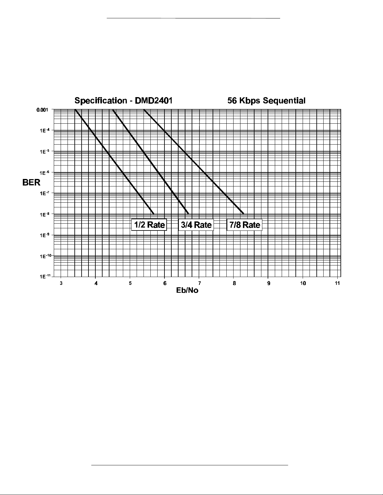
4.4 DMD2401 Bit Error Rate (BER) Curves
Figures 4-1 through 4-4 represent the BER curves for the DMD2401. Included in these specifications are
Viterbi, Concatenated Reed-Solomon and 56 Kbps Sequential.
Page 4-20 TM082 - Rev. 1.0
Page 41
RCF6001 Satellite Terminal Maintenance
TM082 - Rev. 1.0 Page 4-21
Page 42

Maintenance RCF6001 Satellite Terminal
Page 4-22 TM082 - Rev. 1.0
Page 43

RCF6001 Satellite Terminal Maintenance
TM082 - Rev. 1.0 Page 4-23
Page 44

Maintenance RCF6001 Satellite Terminal
Page 4-24 TM082 - Rev. 1.0
Page 45
RCF6001 Satellite Terminal Maintenance
TM082 - Rev. 1.0 Page 4-25
Page 46

Maintenance RCF6001 Satellite Terminal
Page 4-26 TM082 - Rev. 1.0
Page 47

RCF6001 Satellite Terminal ODU Installation
Unpacking the System
Mechanical Inspection
Installation Tools
IFL Cable Installation Guidelines
General Cable Installation Considerations
Mounting the Typical 1, 2 or 4 Watt Outdoor Unit
Interface Connections for the 1, 2 or 4 Watt Outdoor Unit
Mounting the Typical 8 or 16 Watt Outdoor Unit
Interface Connections for the 8 or 16 Watt Outdoor Unit
Installation Verification
Section 5 – Ku-Band Outdoor Unit Installation Procedures
Introduction
This section provides instruction to integrate and install the 3100 Series Outdoor Unit
(ODU) configured for 1-Watt, 2-Watt, 4-Watt, 8-Watt, 16-Watt or 25-Watts. Within this
text ODU refers to any combination of the following elements: BUC (Block
Upconverter), SSPA (Booster Amplifier) and LNB (Low Noise Block Downconverter).
The combination of the noted elements is based upon the system configuration.
Adhere to the installation sequence listed in Table 5-1.
Table 5-1. Installation Sequence
Procedure Section
5.1
5.1.1
5.1.2
5.2
5.2.1
5.3
5.4
5.5
5.6
5.7
TM082 - Rev. 1.0 Page 5-1
Page 48

ODU Installation RCF6001 Satellite Terminal
Unpacking the Outdoor Unit
Each product is completely assembled, tested and then shipped in its appropriate
packaging. Care should be taken when removing equipment from the shipping
container to prevent damage to the units. Ensure that all parts and accessories are
removed from the shipping container and packing material.
Please DO NOT discard the container or any packing material until both a physical and
mechanical inspection of the content has been performed. The container and packing
material must be available if a damage claim is to be made with the carrier.
Step 3. The IDU and ODU are shipped in separate cartons. Remove the ODU from its carton
and verify the contents against the packing slip.
Step 4. The cartons contain the necessary cable connectors, hardware, etc. required to
interconnect the units.
Please adhere to the following procedure when unpacking the shipping container.
Step 3. Remove the tape from the cardboard box flap.
Step 4. Open the box and remove the top foam insert inside the carton.
Step 5. Carefully remove the equipment, manual and accessories.
Step 6. Check for loose components, bent or broken connectors and physical
damage to the outside housing of the equipment.
Step 7. Store the cartons and wrapping material in an appropriate area for future
use.
Step 5. If the shipping container is to be discarded, do not discard the cartons until the contents
has been inspected and all material as been accounted for.
Step 6.
Mechanical Inspection
Inspect the equipment for mechanical shipping damage. Make sure that the equipment
frame is free of damage and that no connectors, controls or indicators are broken,
damaged or loose. Should any damage be discovered after unpacking the system,
immediately file a claim with the carrier. A full report of the damage should be made
and a copy forwarded to Radyne ComStream. Radyne ComStream will then advise
on disposition of the equipment.
Page 5-2 TM082 - Rev. 1.0
Page 49

RCF6001 Satellite Terminal ODU Installation
Inventory the Equipment
The equipment and accessories should be inspected for damage that may have
occurred during shipment. If the containers are damaged notify Radyne
ComStream and the freight carrier immediately. Inventory the equipment as follows:
Check the contents of the cartons against the packing slip provided or the list below, to
ensure that the shipment is complete. The standard VSAT package should include:
Qty 1
Qty 1 Qty (1) 2-Watt 3110-000, 4-Watt 3111-000, 8-Watt 3112-0030 or 16-
Qty 1
Qty 1 Qty (1) 31XX Ancillary hardware / connector kit
Installation Tools
A list of basic tools required to complete installation of the VSAT Satellite System is
provided for reference:
Qty (1) 3130-0000 (3100 series) VSAT Indoor Unit (IDU)
Watt 3113-0030 Outdoor Unit (ODU).
Qty (1) 2660-300X Low Noise Block (LNB)
++ Box end wrenches and/or crescent wrenches
++ Phillips screwdriver
++ Sealing tape (butyl rubber type) and plastic tape to protect / waterproof
++ Antenna mounting hardware
IFL Cable Installation Guidelines
The lengths of the inter-connecting (IFL) cables will vary, the actual length will be
determined by the site layout. Therefore, the user must supply the cables. The transmit
inter-connection requires one double shielded 50Ω coaxial cable with a Type “N” Male
Connector at each end. The receiver cable requires one 75Ω coaxial cable with a Type
“N” Male Connector at the IDU end and a Type “F” Male at the LNB end.
For lengths up to 200 ft, RG-214 cable or equivalent is recommended for the TX side.
Alternate cable types may be used so long as the attenuation at 1 GHz and the center
conductor DC resistance is similar to RG-214 specifications. For lengths between 200
and 300 feet, a low loss foam dielectric cable such as Belden 9914 is required.
Such cable must have an insertion loss of less than 6 dB per 100 feet at 1 GHz and a
center conductor DC resistance of less than 0.12 ohms per 100 feet.
Step 7. Refer to Table 5-2, IDU to ODU Interface Cable Requirements.
TM082 - Rev. 1.0 Page 5-3
Page 50

ODU Installation RCF6001 Satellite Terminal
Step 8. Failure to use the lower loss cable for extended lengths will result in significant
reduction in ODU output power and excessive signal distortion.
Table 5-2 IDU to ODU Interface Cable Requirements
Cable Type Impedance Loss per 100 Meters
RG-214
Belden 8214 50 Ohms 23.0 dB
Belden 9914 50 Ohms 19.7 dB
General Cable Installation Considerations
50 Ohms
36.6 dB
General guidelines to ensure that the IDU to ODU Coaxial Cables are properly
prepared and installed are listed below:
1) Plan the route that the IFL cables will follow. Plan the route to minimize the
cable length between the IDU and ODU. Keep in mind that approximately five
feet at both ends should be added for drip loops and service loops.
2) Ensure that a strain relief is added to both cable connections.
3) Ensure that the external connector is sealed and waterproofed.
4) When running the cable between the IDU and ODU, follow standard installation
practices. Avoid sharp corners. Secure the cable to the tower members, cable
runways or other using hangers or manufacturer’s approved tie-wraps at one
meter (three-foot) intervals.
5) Ensure that the center pin of the type “N” male connector does not protrude
beyond the inner metal ground shield. An improper terminated cable will
damage the mating connectors of the IDU and ODU.
Page 5-4 TM082 - Rev. 1.0
Page 51

RCF6001 Satellite Terminal ODU Installation
Mounting the Typical 1, 2 or 4 Watt Outdoor Unit
The following diagram and instructions pertain to mounting a 3100 Series ODU and
LNB to an antenna using a Radyne ComStream supplied mounting plate. The
mounting plate along with the miscellaneous hardware kits are not provided with the
system unless specified or requested per the USER purchase order.
ODU Mounting Kits
BUC Mounting Kit Description (3110-0003)
The BUC mounting kit provides the mechanical support hardware for mounting the
BUC to a Prodelin offset feed dish with aperture size of 1.8m, 2.4m and 3.8m.
Step 9. Refer to Figure 5-1 and Table 5-3.
BUC Miscellaneous Hardware Kit Description (3110-0001)
The BUC miscellaneous hardware kit contains the hardware and "O" ring for
connecting a BUC to a feed system. This hardware is separate from the mounting kit
described above since this hardware is required for all types of antenna systems.
Attaching the ODU (BUC) / Feed Assembly
This document describes the steps required to assemble and integrate the Radyne
ComStream Ku-Band BUC to a Prodelin antenna system. This document does not
describe the installation instructions for the antenna system. Please refer to antenna
manufacturer’s manual. The following steps outline the procedure to attach the
Radyne ComStream BUC and LNB to the antenna feed support.
TM082 - Rev. 1.0 Page 5-5
Page 52

ODU Installation RCF6001 Satellite Terminal
Figure 5-1. ODU (BUC) Mounting Configuration
Step 7
OMT is not provided
as part of the ODU.
This assembly is
provided by the user.
1
Step 2
Feed Support
LNB
13 1412
13 1412
Step 1
64
8
7
5 6
Step 6
Step 4
Step 5
10 119
2
8
Step 3
Step 1. Insert one “O” Ring (item 12) into the grooved flange of the ODU output
flange. Attach feed assembly (horn and OMT) to the output flange of the
BUC as shown in Figure 4-1, using four each #6 lock washers (item 14)
and 6-32x5/8 screws (item 13). Loosely insert all four screws then tighten
securely.
Step 8. Attach the horn support mount (item 1) to the mounting plate using two
1/4-20 flat head screws (item 8). Tighten screws securely.
Step 9. Attach the BUC rear support plate (item 2) to the mounting plate using two
1/4-20 flat head screws (item 8). Tighten screws securely.
Step 10. Place feed assembly and BUC on the mounting plate. The “neck” of the
horn should sit in the cradle of the horn support. Secure horn with top
strap and 1/4-20 bolts and lock washers (provided with antenna system).
Finger tighten bolts.
Step 11. Attach the BUC to the rear support plate using one each 3/8 flat washer
(item 11), 3/8 lock washer (item 10) and 3/8-16 bolt (item 9).
Page 5-6 TM082 - Rev. 1.0
Page 53

RCF6001 Satellite Terminal ODU Installation
Step 10. Radyne ComStream does not provide the OMT assembly. Radyne ComStream can
provide the transmit reject filter as an option.
Table 5-3 ODU (BUC) / Feed Parts List
Item # Part # Description Qty
1 3110-1032 MTG PLATE, HORN SUPPORT 1
2 3110-1033
3 3110-1034 MOUNTING PLATE 1
4 2400-3043-5608 SCRHEXHD 5/16-18 X 1.0” 2
5 2400-3044-140 WASHER, LOCK 5/16 2
6 2400-3045-813 WASHER, FLAT 5/16 OD .88 4
7 2400-3047-009 HEX NUT 5/16-18 2
8 2400-3040-1407 SCR82FL ¼-20 X ¾ 4
9 2400-3043-3808 SCRHEXHD 3/8-16 X 1.25” 1
10 2400-3044-141 WASHER, LOCK 3/8 1
11 2400-3045-814 WASHER, FLAT 3/8 OD .81 1
12 MS9068-025 “O” -RING 2
13 2400-3038-610 SCRPNHD 6-32X5/8 4
14 2400-3044-136 WASHER. LOCK #6 4
15 DIN912-M4X14MM SCREW SOC HD 4
16 DIN127-M4 WASHER, LOCK M4 4
MTG PLATE, BUC REAR SUPPORT
1
Step 11. Items 1-8, 12, 15-16 are part of the BUC Mounting Kit Part Number 3110-0003.
Step 12. Items 9-11 and 13-14 are part of the BUC Miscellaneous Hardware Kit Part Number
3110-0001.
Step 12. Place the feed / BUC assembly onto the antenna feed support and secure
using two 5/16-18x1 hex screws (item 4), four 5/16 flat washers (item 6),
two 5/16 lock washers (item 5) and two 5/16-18 hex nuts (item 7). Tighten
securely.
Step 13. Insert one “O” Ring (item 12) into the grooved flange of the transmit reject
filter. Attach transmit reject filter and LNB to the receive port of the OMT
using four each lock washers (item 16) and socket screws (item 15).
Step 14. Adjust the feed / BUC / LNB assembly to set the desired polarization.
Tighten the horn strap and BUC rear mount bolt securely.
Step 15. The RF head assembly is complete. Refer to antenna system and VSAT
system operation manuals for antenna alignment and system operation.
TM082 - Rev. 1.0 Page 5-7
Page 54

ODU Installation RCF6001 Satellite Terminal
Interface Connections for the 1, 2, or 4 Watt ODU (BUC)
The following describes the various “USER” connections located on the 1-Watt, 2Watt, or 4-Watt ODU (BUC).
1. WR75 Waveguide Flange, Grooved
Function: ODU (BUC) RF Output port
2. WR75 Transmit Reject Filter
(Optional)
Function: Ku-Band RF Connection to
Reject Filter
3. Male Type “F” Female Connector
Function: LNB Interface for L-Band
Output connection to IDU
LNB
2
8
1
6
7
BUC3.VSD
3
4
5
Step 13. Provides +15 Vdc source for LNB from IDU.
Step 14. Refer to Section 5.2, IFL Cable Installation Guidelines.
Step 15. Refer to Section 5.2.1, General Cable Installation Considerations prior to installing the
cable.
Step 16. Refer to Table 5-2, IDU to ODU Interface Cable Requirements.
4. Female Type “N” Connector
Function: ODU (BUC) Interface for L-Band Input connection from IDU
Receives the modulated L-Band (950 - 1450 MHz) signal from IDU.
Interface for a 10 MHz reference, 48 Vdc power, and an FSK monitor and control
(M&C) link.
Refer to Section 5.2, IFL Cable Installation Guidelines.
Step 17. Refer to Section 5.2.1, General Cable Installation Considerations prior to installing the
cable.
Step 18. Refer to Table 5-2, IDU to ODU Interface Cable Requirements.
Page 5-8 TM082 - Rev. 1.0
Page 55

RCF6001 Satellite Terminal ODU Installation
5. SSPA I/F / RS-485 / 48Vdc
Function: Input for 48 Vdc Source and RS-485 communications
Used to route 48 Vdc and the RS-485 communication channel between the ODU
(BUC) and SSPA.
Pins A, C, D, E, H, N, P, and T: Not Used
Pin B MISO
Pin F PIC_CLK
Pin G SS
Pin J GND (Ground) See Note 1.
Pin K +48 Vdc, See Note 1.
Pin L +48 Vdc, See Note 1.
Pin M GND (Ground) See Note 1.
Pin R MOSI
Pin S PIC_SEL
Step 19. Note 1: Pins J, K, L and M are not used (Not Connected) when DC power is applied to
the unit via the IFL coaxial cable center conductor. It is important to note that when DC
power is applied via the IFL coaxial cable center conductor that pins K & L have +48
vdc present.
6. Female type “TNC” Connector
Function: Optional LNB Interface 10 MHz reference and 15 Vdc or 12 Vdc Source
7. ODU (BUC) Mounting Kit
Function: Attaching ODU and LNB to antenna mounting structure
8. OMT / Reject Filter Assembly
Radyne ComStream does not provide this assembly. Radyne ComStream can
provide the transmit reject filter as an option.
TM082 - Rev. 1.0 Page 5-9
Page 56

ODU Installation RCF6001 Satellite Terminal
Mounting the Typical 8-Watt / 16-Watt Outdoor Unit (BUC)
The following diagram and instructions pertain to mounting an 8-Watt or 16-Watt
ODU (BUC) to an antenna using a Radyne ComStream supplied mounting plate
and hardware kits.
The 8-Watt or 16-Watt Outdoor Unit is pre-assembled as shown in Figure 5-2. The
User antenna type and design determine the mounting location of this assembly.
The flexible waveguide is not provided with the mounting kit.
Figure 5-2. 8-Watt / 16-Watt Mounting
Insert Figure 5-2.
Table 5-4 Offset Mounting Kit (3110-0002)
Item Part # Description Qty
1
MS9068-022
2 2400-3038-610 SCRPNHD 6-32x5/5 LG 8
3 2400-3044-136 Washer, Medlock NO. 6 8
4 36015 U-Bolt 2
5 2400-3044-141 Washer, Medlock 3/8 4
6 2400-3045-814 Washer, FL 3/8 OD. 81 4
7 2400-3047-010 Nut, Plain Hex 3/8-16 4
“O” Ring Parker 1
Step 20. Important: Make sure that the “O” Ring is installed and that the waveguide flange is
properly sealed to prevent moisture from entering the waveguide.
Step 2. First secure the bottom section of the ODU mounting assembly by placing
the ODU (BUC) mounting assembly onto the diagonal support member
and secure using (1) U-Bolt and noted hardware.
Step 3. Secure the top section of the ODU (BUC) mounting assembly onto the
cross member (support pole/pipe) and secure using (1) U-Bolt and noted
hardware.
Step 4. If applicable, attach flexible waveguide between the ODU (BUC) and feed
assembly using the hardware noted.
Interface Connections for the 8-Watt / 16-Watt ODU (BUC)
The following describes the various “USER” connections located on the 8-Watt and 16Watt ODU (BUC).
Step 21. This section provides information pertaining to the SSPA interface connections. Refer
to Section 5.4 for ODU (BUC) Interface Connections.
Page 5-10 TM082 - Rev. 1.0
Page 57
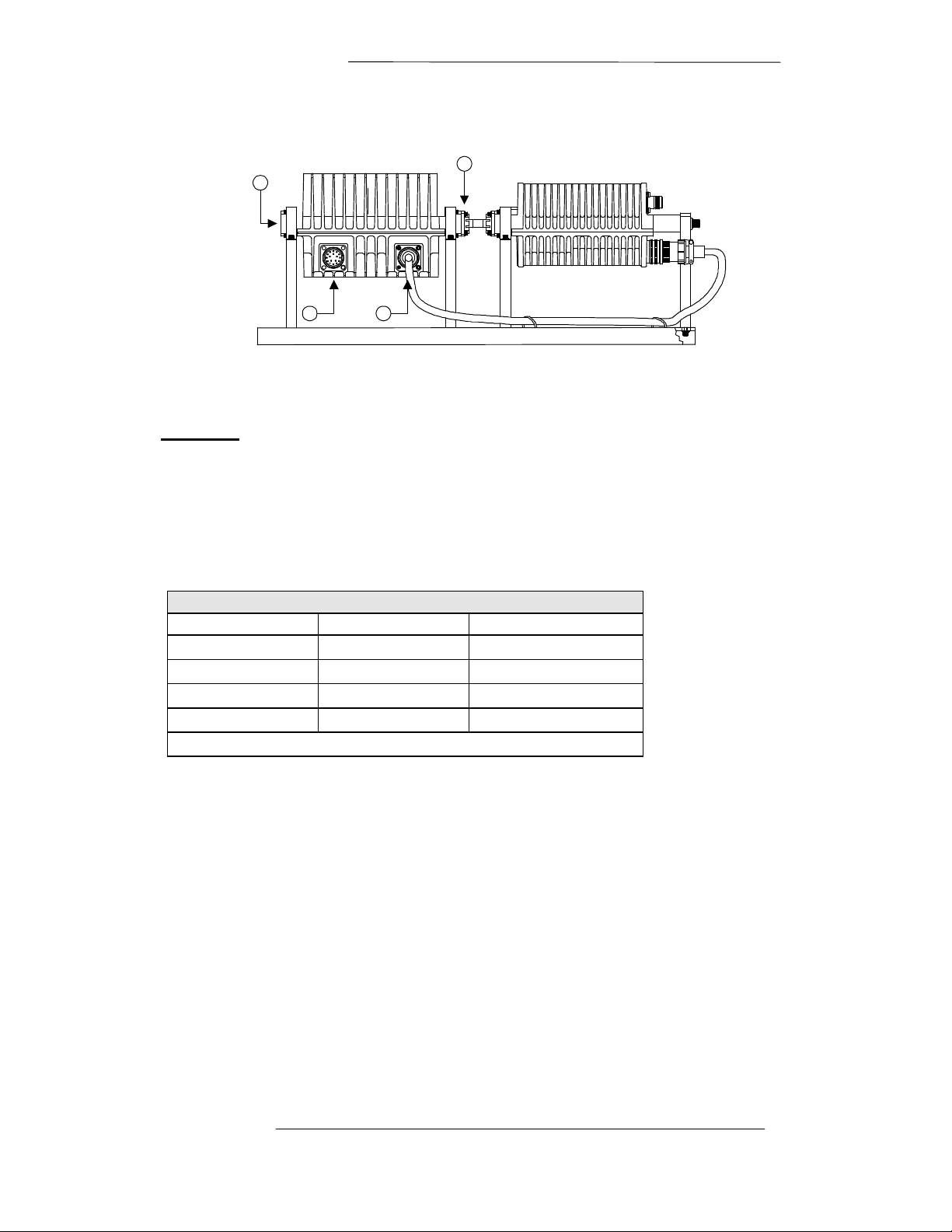
RCF6001 Satellite Terminal ODU Installation
ODU (BUC)
SSPA
Figure 5-3 8-Watt / 16-Watt ODU BUC Connector Details.
4
3
1 2
16BUC.VSD
1. 48Vdc / RS-485 Port
Function: 48 Vdc Interface from AMP Controller
Step 22. 16-Watt Configuration ONLY.
Step 23. Radyne ComStream does not provide the AMP Controller to SSPA 48 Vdc Cable
assembly as part of these systems, only cable connectors are provided. Refer to Table
4-5 for cable wiring information.
Table 5-5 Wiring for 48 Vdc Connector to SSPA
Pin Assignment
Amp Controller SSPA Description
Pin 1 Pin K +48 Vdc
Pin 2 Pin L +48 Vdc
Pin 3 Pin J GND
Pin 4 Pin M GND
* Remaining pins are not used.
Step 24. Recommendation: Use AWG 18 or lower shielded multi-conductor cable.
Step 25. Recommendation: Connect the shields to the ground pins on either end of the cable to
minimize radiated susceptibility and emissions.
2. BUC / SSPA Interface Port
TM082 - Rev. 1.0 Page 5-11
Page 58

ODU Installation RCF6001 Satellite Terminal
Function: Provides the serial interface for communications between the BUC and
SSPA. When configured as an 8-Watt system the 48 Vdc source
voltage for the SSPA is routed through this port. When configured as a
16-Watt system the AMP Controller provides the 48 Vdc source
voltage.
3. WR75 Waveguide Flange, Grooved
Function: SSPA RF Output port to antenna feed
4. Female Type “N” Connector
Function: ODU (BUC) Interface for L-Band Input connection from IDU
Step 26. Receives the modulated L-Band (950 - 1450 MHz) signal from IDU.
Step 27. Interface for a 10 MHz reference, 48 VDC power, and an FSK monitor and control
(M&C) link.
Step 28. Refer to Section 5.2, IFL Cable Installation Guidelines.
Step 29. Refer to Section 5.2.1, General Cable Installation Considerations prior to installing the
cable.
Step 30. Refer to Table 5-2, IDU to ODU Interface Cable Requirements.
Installation Verification
Verify that the following parameters have been adhered to while installing the unit.
6) All equipment located around or mounted directly on the antenna are bonded
together and grounded to a proper earth ground.
7) The unit is located in a manner that allows ease of service.
8) The unit is properly secured in place.
9) All outdoor cable connections are properly seated, secured and waterproofed. A
connector strain relief has been added to each cable end.
Page 5-12 TM082 - Rev. 1.0
Page 59

RCF6001 Satellite Terminal ODU Installation
C-Band Outdoor Unit Installation Procedures
About this section
This section provides instruction to integrate and install the 3100 Series C-band Outdoor Unit
(ODU) configured for any power level. Within this text ODU refers to any combination of the
following elements: BUC (Block Upconverter), SSPA (Booster Amplifier) and LNB (Low Noise
Block Downconverter). The combination of the noted elements is based on the system
configuration.
Step 31. Adhere to the installation sequence listed in Table 4-1.
Table 4-6Installation Sequence
Procedure Section
Unpacking the System 4.1
Mechanical Inspection 4.1.1
Installation Tools 4.1.2
IFL Cable Installation Guidelines 4.2
General Cable Installation Considerations 4.2.1
Mounting the Typical 5 Watt C-band Outdoor Unit 4.3
Interface Connections 5 Watt C-band Outdoor Unit 4.4
Mounting the Typical 10 Watt or higher C-band Outdoor Unit 4.5
Interface Connections for the 10 Watt or higher C-band Outdoor
Unit
Installation Verification 4.7
4.6
Unpacking the Outdoor Unit
Ensure that all parts and accessories are removed from the shipping container and packing
material. Please DO NOT discard the container or any packing material until both a physical and
mechanical inspection of the content has been performed. The container and packing material must
be available if a damage claim is to be made with the carrier.
Step 32. The IDU and ODU are shipped in separate cartons. For higher power applications, the
BUC/Booster are usually mounted and shipped together in a single carton. The cartons contain
the specified cable connectors, hardware, etc. depending on the system configuration as ordered.
Step 33.
Mechanical Inspection
Inspect the equipment for mechanical shipping damage. Make sure that the equipment frame is
free of damage and that no connectors, controls or indicators are broken, damaged or loose.
Should any damage be discovered after unpacking the system, immediately file a claim with the
TM082 - Rev. 1.0 Page 5-13
Page 60

ODU Installation RCF6001 Satellite Terminal
carrier. A full report of the damage should be made and a copy forwarded to Radyne
ComStream. Radyne ComStream will then advise on disposition of the equipment.
Step 34. Subject to terms of the Service Policy, Radyne ComStream will repair all defective equipment. A
Return Material Authorization number must accompany material forwarded to Radyne
ComStream. To obtain an RMA number, call Customer Service at (602) 437-9620.
Inventory the Equipment
The equipment and accessories should be inspected for damage that may have occurred during
shipment. If the containers are damaged notify Radyne ComStream and the freight carrier
immediately. Inventory the equipment as follows:
Check the contents of the cartons against the packing slip provided or the list below, to ensure that
the shipment is complete. The standard VSAT package should include:
Qty (1) 3130-0000 (3100 series) VSAT Indoor Unit (IDU)
Qty (1) 3100 Series Outdoor Unit (ODU)
Qty (1) Low Noise Block (LNB)
Qty (1) Ancillary hardware kit
(Optional Booster and Amp Controller and connector kit as required)
Installation Tools
A list of basic tools required to complete installation of the VSAT Satellite System is provided for
reference:
1) Box end wrenches and/or crescent wrenches
2) Phillips blade screwdriver
3) Sealing tape (butyl rubber type) and plastic tape to protect / waterproof
4) Antenna mounting hardware
IFL Cable Installation Guidelines
The interface between the Indoor Unit and Outdoor Unit is accomplished using two coaxial
cables. The length of the (IFL) cables will depend on the site layout.
Step 35. It is important to note that Radyne ComStream does not provide the IFL interface cables
between the IDU and ODU. The User must supply these cables.
The TX IFL inter-connection requires one double shielded 50Ω coaxial cable with a Type “N”
Male Connector at each end. The RX IFL inter-connection requires one 50Ω or 75Ω-coaxial cable
with a Type “N” Male Connector at the IDU end and a Type “F” Male at the LNB end.
For lengths up to 200 ft, RG-214 cable or equivalent is recommended for the IFL cables.
Alternate cable types may be used as long as the attenuation at 1 GHz and the center conductor
DC resistance is similar to RG-214 specifications. For lengths between 200 and 300 feet, a low
Page 5-14 TM082 - Rev. 1.0
Page 61

RCF6001 Satellite Terminal ODU Installation
loss foam dielectric cable such as Belden 9914 is required. Such cable must have an insertion loss
of less than 6 dB per 100 feet at 1 GHz and a center conductor DC resistance of less than 0.12
ohms per 100 feet.
Step 36. Refer to Table 4-2, IDU to ODU Interface Cable Requirements.
Failure to use the lower loss cable for extended lengths will result in significant reduction in
ODU output power and excessive signal distortion.
Table 4-7IDU to ODU Interface Cable Requirements
Cable Type Impedance Loss per 100 Meters
RG-214
Belden 8214 50 Ohms 23.0 dB
Belden 9914 50 Ohms 19.7 dB
General Cable Installation Considerations
50 Ohms
36.6 dB
General guidelines to ensure that the IDU to ODU Coaxial Cables are properly prepared and
installed are listed below:
1) Plan the route that the IFL cables will follow. Plan the route to minimize the cable length
between the IDU and ODU. Keep in mind that approximately five feet at both ends should
be added for drip loops and service loops.
2) Ensure that a strain relief is added to both cable connections.
3) Ensure that the external connector is sealed and waterproofed.
4) When running the cable between the IDU and ODU, follow standard installation practices.
Avoid sharp corners. Secure the cable to the tower members, cable runways or other using
hangers or manufacturer’s approved tie-wraps at one meter (three-foot) intervals.
5) Ensure that the center pin of the type “N” male connector does not protrude beyond the
inner metal ground shield. An improper terminated cable will damage the mating
connectors of the IDU and ODU.
Mounting the Typical 5-Watt C-Band Outdoor Unit
The following diagram and instructions pertain to mounting a 3100 Series C-band ODU and
LNB to an antenna using a Radyne ComStream supplied mounting plate. The mounting plate
along with the miscellaneous hardware kits are not provided with the system unless specified or
requested per the USER purchase order.
TM082 - Rev. 1.0 Page 5-15
Page 62

ODU Installation RCF6001 Satellite Terminal
Prodelin Antenna BUC Mounting Kit (C-band 3120-0004)
The BUC mounting kit provides the mechanical support hardware for mounting the C-band BUC
to a Prodelin offset feed dish with aperture size of 1.8m, 2.4m and 3.8m. This top assembly kit
contains the 3120-0001 BUC Misc. Hardware Kit and the 0200-935 Antenna Support Kit.
Step 37. Refer to Figure 4-1 and Table 4-3.
BUC Misc. Hardware Kit Description (C-band 3120-0001)
The BUC miscellaneous hardware kit contains the hardware and gasket for connecting a BUC to
a feed system.
Antenna Support Kit Description (0200-935)
The antenna support hardware kit contains the hardware and bracket assemblies required to
properly support the weight of the BUC and feed assembly.
Attaching the ODU (BUC) / Feed Assembly
This installation procedure describes the steps required to install the Radyne ComStream CBand BUC to a Prodelin antenna system. This manual does not describe the installation
instructions for the antenna system. Please refer to antenna manufacturers manual. The steps
outlined below are used to attach the Radyne ComStream BUC and LNB to the feed assembly
and secure to the antenna feed support.
Page 5-16 TM082 - Rev. 1.0
Page 63

RCF6001 Satellite Terminal ODU Installation
Figure 4-4. C-Band BUC to Prodelin Antenna Mounting Configuration
LNB
3120-3000
(FOR REF. ONLY)
7
6
8
16X
8X48X
8X
WR229 GASKET
PART OF 3120-3000
(FOR REF. ONLY)
VSAT FILTER
2426-0000
(FOR REF. ONLY)
4 6
7
8
20X1110X10X
10X
A
BOOM ARM
A
(31200004-1)
OMT
5W BUC (FOR REF. ONLY)
101
104
105
2
102103
8X8X
6
87
4
4X
4X4X 4X
1
202
204
206
207
3X3X
208
3X6X
203
BOOM ARM
201
202
SECTION A-A
TM082 - Rev. 1.0 Page 5-17
Page 64

ODU Installation RCF6001 Satellite Terminal
Step 38. Refer to Table 4-1 for parts list and Figures 4-1, 4-2 and 4-3 for assembly drawing.
Step 5. Insert one Gasket (item 101) into the grooved flange of the ODU output flange.
Attach feed assembly (horn and OMT) to the output flange of the BUC as
shown in Figure 4-1, using quantity eight each 10-32x5/8 screws (item 102)
#10 lock washers (item 103). Loosely assemble all screws and washers then
tighten securely.
Step 6. Attach the Transmit Reject Filter and LNB to the receive port of the OMT as shown
in Figure 4-1.
Step 16. Attach the BUC Tail Mount Bracket (item 2) to the mounting plate (item 1) using
hardware (items 6, 7 & 14) as shown in Figure 4-2. Tighten screws securely.
Step 17. Assemble Mounting Plate (item 1) to the Boom Arm with the Feed Support Bracket
(both supplied with antenna) using hardware (items 4, 6, 7 & 8) as shown in Figure
4-1.
Step 18. Install Bracket Assembly (item 201) and Mounting Plate (item 203) to the Boom
Arm using Hardware (items 204, 206, 207, 208) as shown in Section A-A, Figure
4-1. Do not tighten hardware at this stage.
Step 19. Attach the support brace (item 202) to the mounting plate (item 1) as shown in
Figure 4-2. Please note, some kits may require additional support brackets, (item
15), to attach the support brace to the mounting plate, see Figure 4-3.
Step 20. Attach the bottom of the Support Brace (item 202) to the Boom Arm using the
mounting assembly installed in Step 5 as shown in Section A-A, Figure 4-1.
Loosely assemble all screws, nuts and washers then tighten securely.
Step 21. Place feed assembly and BUC on the mounting plate. The “neck” of the horn should
sit in the cradle of the horn support. Attach the BUC to the rear support plate using
one each 3/8-16 bolt (item 104), 3/8 lock washer (item 105) and 3/8 flat washer
(item 106). Do not tighten completely.
Step 22. Secure horn with top strap and 1/4-20 bolts and lock washers (provided with
antenna system). Finger-tighten bolts.
Step 23. Adjust the feed / BUC / LNB assembly to set the desired polarization. Tighten the
horn strap and BUC rear mount bolt securely. The RF head assembly is complete.
Refer to antenna system and VSAT system operation manuals for antenna alignment
and system operation.
Step 39. Radyne ComStream does not provide the OMT assembly. Radyne ComStream can provide the
transmit reject filter as an option.
Page 5-18 TM082 - Rev. 1.0
Page 65

RCF6001 Satellite Terminal ODU Installation
Table 4-8C-Band ODU (BUC) / Feed Parts List
(3120-0004)
Item # Part # Description Qty
1 3120-1032 MTG PLATE, HORN SUPPORT 1
2 3110-1042 BRACKET-OFFSET, BUC TAIL MOUNT 1
3 0200-935 PRODELIN SUPPORT KIT (See Below) 1
4 2400-3034-1409 SCRHEXHD 1/4-20X1.0” 22
6 2400-3044-139 WASHER, MEDLOCK, 1/4 24
7 2400-3045-810 WASHER, FLAT 1/4 OD.62 42
8 2400-3047-008 NUT,PLAIN HEX 1/4-20 22
11 22117P2 GASKET, WR229 1
13 3120-0001 MISC. KIT (See Below) 1
14* 2400-3039-1408 SCRSKTHD, 1/4-20X7/8LG 2
15* 3120-5610 BRACE, SUPPORT 2
(3120-0001)
101 16267P2 GASKET 1
102 2400-3039-1008 SCRSKTHD 10-32X5/8LG 8
103 2400-3044-138 WASHER, MEDLOCK #10 8
104 2400-3043-3808 SCRHXHD 3/8-16X1LG 1
105 2400-3044-141 WASHER, MEDLOCK 3/8 1
106 2400-3045-814 WASHER, FLAT 3/8 OD.81 1
(0200-935)
201 0490-588 BRACKET ASSY, MTG 1
202 0490-667 SUPPORT BRACE 1
203 0156-058 PLATE, MTG 1
204 2400-3043-1416 SCRHEXHD 1/4-20X2LG 3
205 2400-3043-1418 SCRHEXHD 1/4-20X2.5LG 1
206 2400-3044-139 WASHER, MEDLOCK, 1/4 6
207 2400-3045-811 WASHER, FLAT 1/4 OD .73 12
208 2400-3047-008 NUT,PLAIN HEX 1/4-20 6
209 2400-3043-1408 SCRHXHD, 1/4-20X7/8LG 2
* May not be supplied with all kits.
TM082 - Rev. 1.0 Page 5-19
Page 66
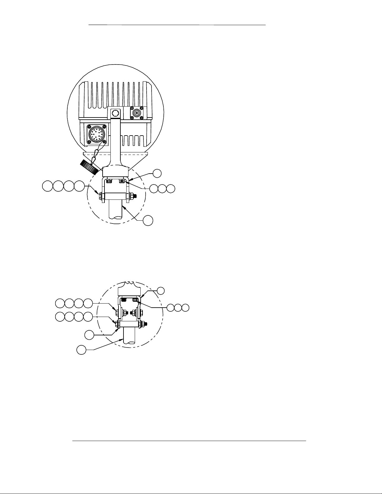
ODU Installation RCF6001 Satellite Terminal
(FOR NARROW ITEM 1 MOD. ONLY)
Figure 4-2 C-Band ODU (BUC) Mounting Configuration End View
1
REF
206205 2072X208
76 14
2X2X2X
202
REF
Figure 4-3 Alternate Mounting for Narrow Bracket
2X 2X
206 208
205 206
REF
4X
207209
207
2X
2X
2X
208
15
202
DETAIL B
1 REF
2X62X
7
14
2X
Page 5-20 TM082 - Rev. 1.0
Page 67

RCF6001 Satellite Terminal ODU Installation
Interface Connections for the 5-Watt Ku-band ODU (BUC)
The following describes the various “USER” connections located on the 5-Watt C-band ODU
(BUC).
WR137 Waveguide Flange, Grooved
Function: ODU (BUC) RF Output port
3
1
CPR229Transmit Reject Filter (Optional)
Function: C-Band RF Connection to Reject
2
Male Type “F” Female Connector
Function: LNB Interface for L-Band Output
3
Filter
8
connection to IDU
Step 40. Provides +15 VDC source for LNB from IDU.
Step 41. Refer to Section 4.2, IFL Cable Installation Guidelines.
Step 42. Refer to Section 4.2.1, General Cable Installation Considerations prior to installing the cable.
Step 43. Refer to Table 4-2, IDU to ODU Interface Cable Requirements.
2
6
1
7
5
4
Female Type “N” Connector
4
Function: ODU (BUC) Interface for L-Band Input connection from IDU
Step 44. Receives the modulated L-Band (950 - 1525 MHz) signal from IDU.
Step 45. Interface for a 10 MHz reference, 48 VDC power, and an FSK monitor and control (M&C) link.
Step 46. Refer to Section 4.2, IFL Cable Installation Guidelines.
Step 47. Refer to Section 4.2.1, General Cable Installation Considerations prior to installing the cable.
Step 48. Refer to Table 4-2, IDU to ODU Interface Cable Requirements.
TM082 - Rev. 1.0 Page 5-21
Page 68

ODU Installation RCF6001 Satellite Terminal
SSPA - RS-485 / 48 Vdc
5
Step 49. Note 1: Pins J, K, L and M are not used (Not Connected) when DC power is applied to the unit
Function: Input for 48 Vdc Source and RS-485 communications.
Used to route 48 Vdc and the RS-485 communication channel between the ODU (BUC) and
SSPA.
Pins A, C, D, E, H, N, P, and T: Not Used
Pin B MISO
Pin F PIC_CLK
Pin G SS
Pin J GND (Ground) See Note 1.
Pin K +48 Vdc, See Note 1.
Pin L +48 Vdc, See Note 1.
Pin M GND (Ground) See Note 1.
Pin R MOSI
Pin S PIC_SEL
via the IFL coaxial cable center conductor. It is important to note that when DC power is applied
via the IFL coaxial cable center conductor that pins K & L have +48 Vdc present.
Female type “TNC” Connector
6
Function: Optional LNB Interface 10 MHz reference and 15 Vdc or 12 Vdc Source for
externally phase locked LNBs.
ODU (BUC) Mounting Kit
Function: Attaching ODU and LNB to antenna mounting structure
7
OMT / Reject Filter Assembly
Radyne ComStream does not provide this assembly. Radyne ComStream can provide the
8
transmit reject filter as an option.
Page 5-22 TM082 - Rev. 1.0
Page 69

RCF6001 Satellite Terminal ODU Installation
Mounting the Typical C-Band High Power Outdoor Unit Assembly
The following diagram and instructions pertain to mounting a 10-Watt, 20-Watt, 40-Watt or
60-Watt ODU (BUC) to an antenna using a Radyne ComStream supplied mounting plate and
hardware kits.
The Outdoor Unit is pre-assembled as shown in Figure 4-3. The User antenna type and design
determine the mounting location of this assembly. Refer to Table 4-4 for the mounting kit parts
list. The flexible waveguide is not provided with the mounting kit.
Table 4-9Offset Mounting Kit (3120-0002)
Item Part # Description Qty
1
16267P2
2 2400-3038-1008 SCRPNHD 10-32x5/8 LG 16
3 2400-3044-138 Washer, Medlock NO. 10 16
4 36015 U-Bolt 2
5 2400-3044-141 Washer, Medlock 3/8 4
6 2400-3045-814 Washer, FL 3/8 OD. 81 4
7 2400-3047-010 Nut, Plain Hex 3/8-16 4
Gasket 2
Step 50. Important: Make sure that the Gasket is installed and that the waveguide flange is properly
sealed to prevent moisture from entering the waveguide.
Step 7. First secure the bottom section of the ODU mounting assembly by
placing the ODU (BUC) mounting assembly onto the diagonal support
member and secure using (1) U-Bolt and noted hardware.
Step 8. Secure the top section of the ODU (BUC) mounting assembly
onto the cross member (support pole/pipe) and secure using (1) U-Bolt and
noted hardware.
Step 9. If applicable, attach flexible waveguide between the ODU (BUC)
and feed assembly using the hardware noted.
TM082 - Rev. 1.0 Page 5-23
Page 70

ODU Installation RCF6001 Satellite Terminal
Step 3
Figure 4-4 Typical 10-Watt / 20-Watt Mounting
Step 2
Step 1
4
4
6
5
7
2
6
5
7
BUC and Booster shown for reference only.
Configurations may vary.
3
8
1
Page 5-24 TM082 - Rev. 1.0
Page 71

RCF6001 Satellite Terminal ODU Installation
C Band ODU
Interface Connections for the High Power C-Band ODU Assemblies
The following describes the various “USER” connections located on the 10-Watt, 20-Watt, 40Watt and 60-Watt ODU Assemblies.
Step 51. This section provides information pertaining to the SSPA interface connections. Refer to Section
4.4 for ODU (BUC) Interface Connections.
Figure 4-5 10-Watt thru 60-Watt ODU SSPA Connector Details
3
C Band SSPA
1
(5W BUC)
2
10-Watt system is shown for reference.
4
48VDC / RS-485 Port
1
Function: 48 VDC Interface from AMP Controller
Step 52. 20 Watt, 40 Watt and 60 Watt Configurations ONLY.
Step 53. Radyne ComStream does not provide the AMP Controller to SSPA 48 VDC Cable assembly as
part of these systems, only cable connectors are provided. Refer to Table 4-5 for cable wiring
information.
Table 4-10 Wiring for 48 Vdc Connector to SSPA
Step 54. Recommendation: Use AWG 18 or lower shielded multi-conductor cable.
Step 55. Recommendation: Connect the shields to the ground pins on either end of the cable to minimize
Pin Assignment
Amp Controller SSPA Description
Pin 1 Pin K +48 VDC
Pin 2 Pin L +48 VDC
Pin 3 Pin J GND
Pin 4 Pin M GND
* Remaining pins are not used.
radiated susceptibility and emissions.
TM082 - Rev. 1.0 Page 5-25
Page 72

ODU Installation RCF6001 Satellite Terminal
2. BUC / SSPA Interface Port
Function: Provides the serial interface for communications between the BUC and SSPA.
When configured as a 10-Watt system the 48VDC source voltage for the SSPA
is routed through this port. When configured as a 20-Watt system the AMP
Controller provides the 48VDC source voltage. This cable is provided with the
system.
3. WR137 Waveguide Flange, Grooved
Function: SSPA RF Output port to antenna feed
4. Female Type “N” Connector
Function: ODU (BUC) Interface for L-Band Input connection from IDU
Step 56. Receives the modulated L-Band (950 - 1525 MHz) signal from IDU.
Step 57. Interface for a 10 MHz reference, 48 VDC power, and an FSK monitor and control (M&C) link.
Step 58. Refer to Section 4.2, IFL Cable Installation Guidelines.
Step 59. Refer to Section 4.2.1, General Cable Installation Considerations prior to installing the cable.
Step 60. Refer to Table 4-2, IDU to ODU Interface Cable Requirements.
Installation Verification
Verify that the following parameters have been adhered to while installing the unit.
10) All equipment located around or mounted directly on the antenna are bonded together and
grounded to a proper earth ground.
11) The unit is located within or in a manner that allows ease of service.
12) The unit is properly secured in place.
13) All outdoor cable connections are properly seated, secured and waterproofed. A connector
strain relief has been added to each cable end.
Page 5-26 TM082 - Rev. 1.0
Page 73

RCF6001 Satellite Terminal ODU Installation
TM082 - Rev. 1.0 Page 5-27
Page 74

ODU Installation RCF6001 Satellite Terminal
Page 5-28 TM082 - Rev. 1.0
Page 75

Appendix A
DMD2401 LB/ST Satellite Modem Technical Specifications
A.1 Introduction
This section defines the technical performance parameters and requirements for the DMD2401 Satellite
Modem.
Page 76

Operation RCF6001 Satellite Terminal
DMD2401 LB/ST Technical Specifications
Transmit and Receive Data Rates
DMD2401LB BPSK - 9.6 to 1024 Kbps, Rate 1/2 (Standard)
QPSK - 19.2 to 2048 Kbps, Rate 1/2 (Optional)
QPSK - 28.8 to 2048 Kbps, Rate 3/4 (Optional)
QPSK - 33.6 to 2048 Kbps, Rate 7/8 (Optional)
Data Rate Setting: Selectable in 1 bps steps
Modulator/Tx Specifications
Frequency 950-1525 MHz
Reference Frequency Signal 10 MHz
Reference Stability 1x10
Optional 1x10⁻⁸, 1x10
-7
-9
Frequency Resolution 100 Hz
Output Level -5 to -30 dBm
Phase Noise
100 Hz -60 dBc
1000Hz -70 dBc
10 KHz -75 dBc
100 KHz -85 dBc
Spurious and Harmonics -50 dBc
Impedance 50 ohms
Return Loss 14 dB
Output Voltage
Output Current
10 MHz Reference levels -10 dBm, ± 5 dB
Connector SMA
Demodulator/Rx Specifications
Frequency 950-1525 MHz
Frequency Resolution 100 Hz
Carrier Acquisition ± 30 KHz
Input Carrier Range -65 to -40 dBm
(Symbol Rate <64 KHz)
-50 to -30 dBm
(Symbol Rate >640 KHz)
Aggregate Power Min. of -10 dBm or 35 dBc
Impedance 50-ohm
Return Loss 8 dB Min.
Output Voltage
Output Current
10 MHz Reference levels -10 dBm, ± 5 dB
Connector Type-F
Typical Eb/No (Viterbi) Rate 1/2 Rate 3/4 Rate 7/8
@ BER=10
@ BER=10
-5
-7
5.1 6.2 7.5
6.2 7.7 8.6
Typical Eb/No, @ 64 Kbps
Sequential Rate 1/2 Rate 3/4 Rate 7/8
@ BER=10
@ BER=10
-5
-7
4.0 5.0 6.1
4.9 5.9 7.4
Descrambler: Intelsat V.35, mode selectable
Data Buffering: 8 bits to 262,144 bits, in 8-bit steps
Terrestrial Interfaces: RS-449/422, RS232 or V.35
Page 3-2 TM082 Rev. 1.0
Page 77

RCF6001 Satellite Terminal Operation
Summary Alarms: Two separate form-C contacts
available at the rear panel. Each
provides a summary alarm of fault conditions.
Front Panel LED Indicators
Alarms
Unit: Power
Demodulator: Signal Lock
Modulator: Transmit On
Alarm
Event
Remote
Major Alarm
Minor Alarm
Test Mode
Major Alarm
Minor Alarm
Test Mode
Monitor and Control
All operating parameters can be monitored and controlled via the front panel display/keypad or the RS485 or
RS232 serial control channel in either terminal or command modes. The following modem parameters may be
controlled and/or monitored:
Transmit and Receive Frequencies
Transmit and Receive Offsets
Modulator Power Level
Modulator On/Off
Modulator/Demodulator Modulation (BPSK, QPSK or OQPSK)
Modulator/Demodulator Data Rates (1 bps steps)
Modulator/Demodulator Code Rates (1/2, 3/4, 7/8)
Modulator/Demodulator Differential Decoders (On/Off)
Modulator/Demodulator Scrambler (On/Off)
Modulator/Demodulator Data (inverted or non-inverted)
Modulator/Demodulator Clock Source and Phase
Demodulator FIFO Size, Delay and Status
Demodulator Eb/No
Demodulator Low Eb/No
Demodulator Measure BER and Estimated BER
Modulator/Demodulator Alarms
Options
Concatenated Codec: A Reed-Solomon codec is available.
Asynchronous Channel: Asynchronous overhead
order-wire applications.
Viterbi and Sequential Coding
Environmental
Prime Power: 100-240 Vac, 50-60 Hz, 1.0 A
(IEC 3-pin Power Connector with Switch)
Outdoor Unit Power: 150 Watts, 100 - 240 Vac, Autoranging
Operating Temp.: 0 to 50o C, 95% humidity, non- condensing
Storage Temp.:-20 to 70o C, 99% humidity, non-condensing
Physical
Chassis size: 19 x 17 x 3.5 inches
Weight: 16 pounds (7.2 Kg)
Shipping Weight: 20 pounds (9.0 Kg)
TM082 Rev. 1.0 Page 3-3
channel for remote control and
(48.26 x 43.2 x 4.45 cm)
Page 78

Operation RCF6001 Satellite Terminal
C-Band Block Upconverter Specifications
Electrical Performance Parameters
Output frequency range 5.85 – 6.425 GHz
Input frequency range 950 – 1525 MHz
Input level range -5 to –55 dBm (-20 for P1dB)
Reference signal frequency 10 MHz
Reference signal level -3 to +10 dBm
Power levels Available up to 40 watts
Ku-Band Block Upconverter Specifications
Electrical Performance Parameters
Output frequency range 14.0 – 14.4 GHz
Input frequency range 950 – 1525 MHz
Input level range -5 to –55 dBm (-20 for P1dB)
Reference signal frequency 10 MHz
Reference signal level -3 to +10 dBm
Power levels Available up to 25 watts
(The following specifications apply to both C- and Ku-Band Bucs)
Intermodulation IM
(Two tone signal with 5 MHz distance and a summary output power
of 6 dB below rated power, 6 dB back off)
Gain stability ± 0.5 dB/day at constant temperature
Gain variation (flatness) ± 2 dB over 500 MHz
(over freq. and temp.) ± 1 dB over any 80 MHz band
Group delay < 10 ns over any 80 MHz band
Carriers transmit interrupt > 50 dB
Local oscillator phase noise < 2.8o RMS double sideband
Spurious < -20 dBm (in-band)
Noise figure < 20 dB
DC input 42 to 60 Vdc (nominal 48V)
3
13.75 – 14.25 GHz (option)
> -30 dBc
(24 Vdc optional)
Page 3-4 TM082 Rev. 1.0
 Loading...