

Page 1

Comtech EF Data is an
AS9100 Rev B / ISO9001:2000 Registered Company
RC-1160 RC-1260
IMPORTANT NOTE: The information contained in this document supersedes all previously published information
Redundancy Switch Controllers
Installation and Operation Manual
regarding this product. Product specifications are subject to change without prior notice.
MN-RC1160RC1260 Revision 1
Page 2

Page 3

Comtech EF Data is an
AS9100 Rev B / ISO9001:2000 Registered Company
RC-1160 RC-1260
Redundancy Switch Controllers
Installation and Operation Manual
Part Number MN-RC1160RC1260
Revision 1
Copyright © Comtech EF Data, 2014. All rights reserved. Printed in the USA.
Comtech EF Data, 2114 West 7th Street, Tempe, Arizona 85281 USA, 480.333.2200, FAX: 480.333.2161
Page 4

Table of Contents Revision 1
RC-1160 RC-1260 Redundancy Switch Controllers RC-1160 RC-1260
Blank Page
.
ii
Page 5

Errata A for MN-RC1160RC1260 Rev 1
Comtech EF Data Documentation Update
Subject:
Update Section 2.3, Added DC power information
Errata Part Number:
PLM CO Number:
Comments:
ERMNRC111260-EA1 (Errata documents are not revised )
C-0032355
See attached page(s). The new information will be included in the next released
revision of the manual.
ERMNRC111260-EA1 Rev - PLM C-0032355
Page 6

ERMNRC111260-EA1 Rev - PLM C-0032355
Page 7

Errata B for MN-RC1160RC1260 Rev 1
Comtech EF Data Documentation Update
Subject:
Update Section 1.2, Revised power output information
Errata Part Number:
PLM CO Number:
Comments:
ERMNRC111260-EB1 (Errata documents are not revised )
C-0032396
See attached page(s). The new information will be included in the next released
revision of the manual.
ERMNRC111260-EB1 Rev - PLM C-0032396
Page 8
ERMNRC111260-EB1 Rev - PLM C-0032396
Page 9

Table of Contents
PREFACE........................................................................................................................................... XIX
About this Manual .............................................................................................................................................. xix
Product Support .................................................................................................................................................. xx
Comtech EF Data Headquarters ....................................................................................................................... xx
Warranty Policy ................................................................................................................................................. xxi
CHAPTER 1. INTRODUCTION ....................................................................................................... 1–1
1.1 Overview ................................................................................................................................................ 1–2
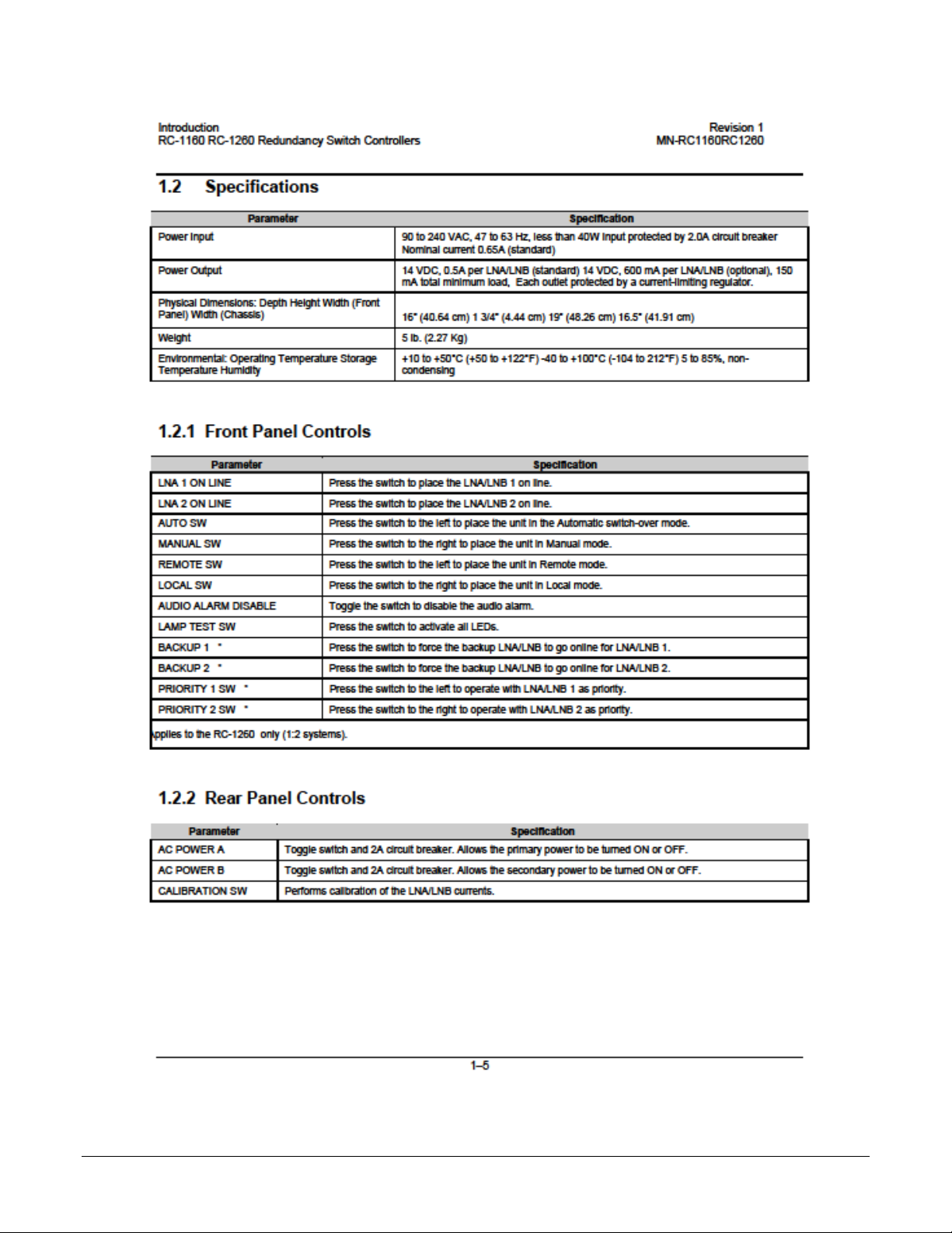
1.2 Specifications ......................................................................................................................................... 1–5
1.2.1 Front Panel Controls........................................................................................................................ 1–5
1.2.2 Rear Panel Controls ......................................................................................................................... 1–5
1.2.3 Indicators ......................................................................................................................................... 1–6
1.2.4 Internal Switches ............................................................................................................................. 1–6
1.2.5 Internal Indicators ........................................................................................................................... 1–6
CHAPTER 2. INSTALLATION ........................................................................................................ 2–1
2.1 Unpacking .............................................................................................................................................. 2–1
2.2 Rack-Mount Installation....................................................................................................................... 2–2
2.3 Power Connection ................................................................................................................................. 2–2
2.4 External Connections ............................................................................................................................ 2–3
2.4.1 LNA/LNB Connector, J1 ................................................................................................................ 2–3
2.4.2 Remote Connector, J2 ..................................................................................................................... 2–5
2.4.3 EIA-485/-232 Serial Connector, J3 ................................................................................................. 2–7
2.4.4 LNA, LNB, and Waveguide Pinouts ............................................................................................... 2–8
CHAPTER 3. OPERATION ............................................................................................................. 3–1
3.1 Status and Control ................................................................................................................................ 3–1
3.1.1 External Controls and Indicators ..................................................................................................... 3–2
3.1.2 LED Indicators ................................................................................................................................ 3–3
3.2 Modes of Operation ............................................................................................................................... 3–4
3.2.1 RC-1160 .......................................................................................................................................... 3–4
3.2.2 RC-1260 .......................................................................................................................................... 3–4
3.2.2.1 Single and Dual Mode ................................................................................................................. 3–4
3.2.2.2 1:1 Configuration Mode .............................................................................................................. 3–
3.2.2.3 Triple Single Mode...................................................................................................................... 3–4
3.2.2.4 1:1 Redundant Mode ................................................................................................................... 3–5
3.2.2.5 1:2 Redundant Mode ................................................................................................................... 3–5
4
iii
Page 10

Table of Contents Revision 1
RC-1160 RC-1260 Redundancy Switch Controllers RC-1160 RC-1260
3.3 Calibration ............................................................................................................................................. 3–6
3.3.1 Calibration Requirement ................................................................................................................. 3–6
3.3.2 Calibration Failure .......................................................................................................................... 3–6
3.4 Internal Adjustments and Switches ..................................................................................................... 3–7
3.4.1 Power Supply Voltage ..................................................................................................................... 3–7
3.4.2 Current Sensitivity Select (SW1) .................................................................................................... 3–7
3.4.3 Normal/Maintenance Switch (SW1) ............................................................................................... 3–7
3.4.4 Selection of EIA-485/232 ................................................................................................................ 3–8
CHAPTER 4. MAINTENANCE ........................................................................................................ 4–1
4.1 Maintenance ........................................................................................................................................... 4–1
4.2 Troubleshooting ..................................................................................................................................... 4–1
4.3 Servicing with Power ON ..................................................................................................................... 4–1
APPENDIX A. REDUNDANCY DRAWINGS ....................................................................................... 1
APPENDIX B. REMOTE CONTROL ................................................................................................... 1
B.1 General ....................................................................................................................................................... 1
B.2 Message Structure ..................................................................................................................................... 1
B.2.1 Start Character ..................................................................................................................................... 2
B.2.2 Device Address ................................................................................................................................... 2
B.2.3 Command/Response ............................................................................................................................ 3
B.2.4 End Character ...................................................................................................................................... 3
B.2.5 Example Command (Unit in default State) ......................................................................................... 3
B.3 Configuration Commands/Responses ..................................................................................................... 4
APPENDIX C. THEORY OF OPERATION .......................................................................................... 1
C.1 Controller AC Power Supplies ................................................................................................................. 1
C.2 Power/Maintenance Board ....................................................................................................................... 2
C.3 Waveguide Switch Driver ......................................................................................................................... 3
C.4 Front Panel Display ................................................................................................................................... 3
C.5 Logic Control Assembly............................................................................................................................ 4
C.6 Analog Current Sense ............................................................................................................................... 6
iv
Page 11

Table of Contents Revision 1
RC-1160 RC-1260 Redundancy Switch Controllers RC-1160 RC-1260
Tables
Table 2-1. Controller LNA/LNB Output Connector, J1 ........................................................................................ 2–3
Table 2-2. Remote Connector, J2 ....................................................................................................................... 2–5
Table 2-3. EIA-485/-232 Serial Connector, J3 .................................................................................................... 2–7
Table 2-4. LNA, LNB, and Waveguide Pinouts ................................................................................................... 2–8
Figures
Figure 1-1. RC-1160 (1:1) ................................................................................................................................... 1–1
Figure 1-2. RC-1260 (1:2) ................................................................................................................................... 1–1
Figure 1-3. Redundancy Switch Controller Block Diagram ................................................................................. 1–3
Figure 1-4. LNA/LNB Plate Block Diagram ......................................................................................................... 1–4
Figure 2-1. Waveguide Switch Wiring 1:1 Configuration .................................................................................... 2–4
Figure 2-2. Waveguide Switch Wiring 1:2 Configuration, RC-1260 Only ........................................................... 2–4
Figure 2-3. External Remote Local Wiring .......................................................................................................... 2–6
Figure 3-1. RC-1160 Front Panel ........................................................................................................................ 3–2
Figure 3-2. RC-1260 Front Panel ........................................................................................................................ 3–2
Figure 3-3. Rear Panel, RC-1160 and RC-1260 ................................................................................................. 3–2
Figure 3-4. Selection of EIA-232/485 Jumpers ................................................................................................... 3–8
Figure A-1. C-Band LNA 1:1 Redundant System Assembly ................................................................................... 1
Figure A-2. C-Band LNA 1:1 Redundant System (Exploded View) ........................................................................ 2
Figure A-3. C-Band LNB 1:1 Redundant System Assembly ................................................................................... 3
Figure A-4. C-Band LNB 1:1 Redundant System (Exploded View) ........................................................................ 4
Figure A-5. Ku-Band LNA 1:1 Redundant System Assembly ................................................................................. 5
Figure A-6. Ku-Band LNA 1:1 Redundant System (Exploded View) ...................................................................... 6
Figure A-7. Ku-Band LNB 1:1 Redundant System Assembly ................................................................................. 7
Figure A-8. Ku-Band LNB 1:1 Redundant System (Exploded View) ...................................................................... 8
Figure A-7. C-Band LNA 1:2 Redundant System Assembly ................................................................................... 9
Figure A-8. C-Band LNA 1:2 Redundant System (Exploded View) ...................................................................... 10
Figure A-7. C-Band LNB 1:2 Redundant System Assembly ................................................................................. 11
Figure A-8. C-Band LNB 1:2 Redundant System (Exploded View) ...................................................................... 12
Figure A-7. Ku-Band LNA 1:2 Redundant System Assembly ............................................................................... 13
Figure A-8. Ku-Band LNA 1:2 Redundant System (Exploded View) .................................................................... 14
Figure A-7. Ku-Band LNB 1:2 Redundant System Assembly ............................................................................... 15
Figure A-8. Ku-Band LNB 1:2 Redundant System (Exploded View) .................................................................... 16
Figure C-1. Power/Maintenance Board .................................................................................................................. 2
Figure C-2. Logic Control Board Assembly ............................................................................................................. 4
Figure C-3. LNA/LNB Current/Voltage Output ....................................................................................................... 6
v
Page 12

Table of Contents Revision 1
RC-1160 RC-1260 Redundancy Switch Controllers RC-1160 RC-1260
BLANK PAGE
vi
Page 13

Preface Revision 1
WARNING
CAUTION
IMPORTANT
NOTE
RC-1160 RC-1260 Redundancy Switch Controllers MN-RC1160RC1260
PREFACE
About this Manual
This manual gives installation and operation information for the Comtech EF Data RC-1160 RC1260 Redundancy Switch Controllers. This manual is intended for anyone who installs or
operates the unit.
Cautions and Warnings
indicates a potentially hazardous situation that, if not avoided, could result
in death or serious injury.
indicates a hazardous situation that, if not avoided, may result in minor or
moderate injury. CAUTION may also be used to indicate other unsafe practices or
risks of property damage.
or
statement that is associated with the task being performed.
Patents and Trademarks
See all of Comtech EF Data’s Patents and Patents Pending at http://patents.comtechefdata.com.
Comtech EF Data acknowledges that all trademarks are the property of the trademark owners.
Military Standards
References to “MIL-STD-188” apply to the 114A series (i.e., MIL-STD-188-114A), which
provides electrical and functional characteristics of the unbalanced and balanced voltage digital
interface circuits applicable to both long haul and tactical communications. Specifically, these
references apply to the MIL-STD-188-114A electrical characteristics for a balanced voltage
digital interface circuit, Type 1 generator, for the full range of data rates. For more information,
refer to the Department of Defense (DOD) MIL-STD-188-114A, “Electrical Characteristics of
Digital Interface Circuits.”
indicates information critical for proper equipment function, or a
xix
 Loading...