

Page 1

RCU101
1:1 Converter Protection Switch
Installation and Operation Manual
Part Number TM055
Revision 2.2
May, 2002
IMPORTANT NOTE: The information contained in this document supersedes all previously
published information regarding this product. This manual is subject to change without prior notice.
Part Number TM055 Revision 2.2
Page 2

Copyright © 2002 Comtech EF Data. All rights reserved. Printed in the USA. Comtech EF Data,
2114 West 7th Street, Tempe, Arizona 85281 USA, 480.333.2200, FAX: 480.333.2161
Page 3

RCU101 1:1 Protection Switch Warr anty Policy
RADYNE COMSTRE AM WARRANTY POLICY
WARRANTY AND SERVICE
Radyne ComStr eam (Sel ler) warrants the i tems manufactured and sold by Radyne ComSt r eam to be free
of defects in material and workmanship for a period of two (2) years from date of shipment Radyne
ComStream's obli gation under its warranty is li mit ed in accordance with the periods of time and all other
conditi ons stat ed in all pr ovisions of this warranty.
This warranty appl ies only to defects in material and workmanship in products manufactured by Rady ne
ComStream. Radyne ComStream makes no warranty whatsoever concerning products or accessories not
of its manuf ac ture.
Repair, or at Radyne ComStr eam's option, r eplacement of the Rady ne ComStream products or defective
parts therein shal l be the sole and ex c lusive remedy for al l v alid warranty c laim s.
WARRANTY PERIOD
The applic able warranty peri od shal l commence on the date of shipment fr om Radyne ComS tream's
facility to the original purchaser and extend for the stated period following the date of shi pment. Upon
beginning of the applicable Radyne ComStream warranty period, all c ustomer's remedies shall be
governed by the term s stated or r eferenced in this warranty. In-warranty repai r ed or replacement products
or parts are warranted only for the remaining unexpir ed por tion of the original warranty period applic able
to the repaired or replaced produc ts or parts. Repair or r eplacement of products or parts under warranty
does not extend the or iginal warrant y per iod.
WARRANTY COVERAGE LIMITATIONS
The following are expressly not covered under warranty:
1. Any loss, damage and/or mal function relating in any way to shipping, storage, acc ident, abuse,
alteration, m isuse, neglect, failure to use products under normal operat ing conditions, failure to use
products accordi ng to any operating instructions provided by Radyne ComS tream, lack of routine care and
maint enanc e as indicated in any operating maint enanc e instructions, or failure to use or t ak e any pr oper
precautions under t he c ircumstanc es.
2. Products, i tems, parts, ac c essori es, subassembl ies, or com ponents which are expendable in normal
use or are of l imi ted life, such as but not limited to, bulbs, fuses, lamps, glassware, etc.
TM055 - Rev. 2.2 ii
Page 4

Warr ant y Pol icy RCU101 1:1 Protection Switch
Radyne ComStr eam reserves the right to revise the f or egoing li st of what is covered under this warranty.
WARRANTY REPLACEMENT AND ADJUSTMENT
Radyne ComStream will not make warranty adjustments for failures of products or parts which occur after
the specif ied maxim um adjustment period. Unless otherwise agreed, failure shall be deemed to have
occurred no m or e than seven (7) working days before t he first date on which a notic e of f ailure is received
by Radyne ComSt ream. Under no c ircumst anc es shall any warranty ex c eed the period stated above
unless expressly agreed to in writi ng by Rady ne ComStream.
LIABILITY LIMITATIONS
THIS WARRANTY IS EXPRESSLY IN LIEU OF AND EXCLUDES ALL OTHER EXPRESS AND IMPLIED
WA RRA NTIES, I NCLUDING BUT NOT LIMITE D TO WARRANTIE S OF MERCHANTA B ILITY AND O F
FITNESS FOR PARTICULAR PURPOSE, USE, OR APPLICATIONS, AND ALL OTHER OBLIGATIONS
OR LIABILITIES O N T HE PART OF RADYNE COMSTREAM, UNLESS SUCH OTHER WA RRANT IES,
OBLIGATIONS, OR LIABILITIES ARE EXPRESSLY AGREED TO IN WRITING BY RADYNE
COMSTREAM.
All obligations of Radyne Com S tream under this warranty shall c ease i n the event its product s or parts
thereof have been subjec ted to accident, abuse, alt er ation, misuse or neglect, or which have not been
operated and maintained in accordance with pr oper oper ating instruc tions.
IN NO EVENT SHALL RADYNE COMSTREAM BE LIABLE FOR INCIDENTAL, CONSEQUENTIAL,
SPECIAL OR RESULTING LOSS OR DAMAGE OF ANY KIND HOWSOEVER CAUSED. RADYNE
COMSTREAM’S LIABILITY FOR DAMAGES SHALL NOT EXCEED THE PAYMENT, IF ANY,
RECEIVED BY RA DY NE COMSTREAM F OR THE UNIT OR PRODUCT OR S E RV ICE FURNISHED OR
TO BE FURNISHED, AS THE CASE MAY BE, WHICH IS THE SUBJECT OF CLAIM OR DISPUT E .
Statem ents made by any person, including representatives of Rady ne ComStream, which are inconsistent
or in conflic t with the terms of t his warranty, shall not be binding upon Radyne ComStream unless reduced
to writi ng and appr oved by an officer of Radyne ComSt r eam.
WARRANTY REPAIR RETURN PRO CE DURE
Before a warrant y r epair can be accomplished, a Repair Authorization must be received. It is at this time
that Radyne ComStream will authorize the product or part be returned to t he Rady ne ComStream fac ility
or if field repair will be accomplished. The Repai r A uthorization may be r equested in writi ng or by c alling:
Radyne ComStream Corporation
3138 E. Elwood St.
Phoenix, Arizona 85034 ( US A )
Attn: Customer Support
Phone: (602) 437-9620 F ax: (602) 437-4811
Any product returned to Radyne Com S tream for examination must be sent prepaid v ia the means of
transportation indicated as acceptable to Radyne ComStr eam. Return A uthorizat ion Number must be
clearly marked on t he shi pping label . Returned products or parts should be carefully packaged in the
original container , if possible, and unless otherwise indicated, shipped to the above address.
NON-WARRANTY REPAIR
When a pr oduc t is returned for any reason, Customer and its shipping agency shall be r esponsible for all
damage result ing from improper packi ng and handling, and for loss in t r ansi t, not withstanding any defec t
or nonconformit y in the product. By returning a product, the owner grants Radyne ComSt r eam perm ission
to open and disassemble t he pr oduc t as required f or evaluation. In all c ases, Radyne ComStream has
sole responsibility for determining the cause and nature of fai lure, and Radyne ComStream's
determination wit h r egar d thereto shall be final
.
TM055 - Rev. 2.2
iii
Page 5

RCU101 1:1 Protection Switch Record of Revisions
RCU101 1:1 Protection Switch
Installation and Operation Manual
TM055 - Record of Revisions
Radyne ComStr eam Corporation is constantly im pr ovi ng its products and therefore the information in this
document is subject to change wit hout prior not ice. Radyne ComStream Corporation makes no warranty
of any kind with regard to this material, includi ng but not limited to the implied warranties of
merchantability and f itness for a particular purpose. No responsibility for any errors or omissions that may
pertain to the mater ial herei n is assumed. Radyne ComS tream Corpor ation mak es no commitment to
update nor to keep cur r ent the informat ion contai ned in this document. Radyne ComStream Corporati on
assumes no responsibility for use of any circuitry other than the circuitry employed in Radyne ComStream
Corporation’s system s and equi pment.
Revision
Level
Date Reason for Change
1 7-15-96 Initial Release
2 11-28-96 Added Illustrati ons of f r ont and rear panels, new interconnection
diagram, added schematics, updated Operation and Maintenance
2.1 2-7-97 Updated Fault Status connector, updated specificat ions
2.2 5-31-02 Added Appendix B
TM055 - Rev. 2.2 iv
Page 6

RCU101 1:1 Protection Switch Table of Contents
Table of Contents
1.0 Introduction….…..……………………………………………………………………………………… 1-1
2.0 Installation Requir ements..… ...……………………………………………………………………… 2-1
2.1 Unpacking..………..…………………………………………………………………………………… 2-1
2.1.1 Removal and Assembly..…………………………………………………………………………… 2-1
2.2 Mounting Considerations.…..………………………………………………………………………… 2-1
2.3 Cabling..………………………………………………………………………………………………… 2-1
2.4 Hardware Interface..…………………………………………………………………………………… 2-4
2.4.1 Protection Switch Interface Connector……………………………………………………………2-4
2.4.2 Switch Fault/Status Connector…….……………………………………………………………… 2-5
2.4.3 RCU101 RF and IF Rear Panel Connectors..……………………………………………………2-5
2.4.4 Interfaces Common to the Converters…………………………………………………………… 2-6
2.4.5 Operator Serial I/O.………………………………………………………………………………… 2-6
2.4.6 Up/Downconverter E quipment RS 485 P ort..…..…………………………………………………2-7
3.0 Operation (Definitions)…….……………………………………………………………………………3-1
3.1 Switch Logic………..……………………………………………………………………………………3-1
3.2 Manual/Auto Mode Selection Switch.….…………………………………………………………….. 3-1
3.3 Switch LEDs…………………………………….……………………………………………………… 3-2
3.4 Troubleshooting and/or Replacing a Fault ed Converter……………………………………………3-2
4.0 Periodic Maintenance…………..………………………………………………………………………4-1
Appendix A - Technical Specifications….…………………………………………………………………A-1
Appendix B - RCU101 Bl ock Diagram, Configuration Drawings and Schematics……………………B-1
TM055 - Rev. 2.2 v
Page 7

TM054 - Rev. 2.2
vi
Page 8
RCU101 1:1 Protection Switch Description
Section 1 - RCU101 1:1 Protection Switch Description
1.0 Introduction
The Radyne ComStream RCU101 1:1 Protection Switch Unit provides automatic circuit
restoration for one online frequency Up or Downconverter. The switch provides complete
isolation of primary and backup converters by providing transfer swit c hing of bot h the RF and IF
signal pat hs. Conv ert er f ault and c ircui t restorat ion i s initi ated f rom the summ ary f ault contacts
of the onl ine conv erter. Upon c learing of the faul t in t he online conv erter, or after replacem ent
of the online converter, the switch can be directed to restore the operation to the online
conver ter ( or the converter t hat i s select ed as the ‘onl ine’ uni t ). A n RS485 Equi pm ent i nt erf ac e
between the converters all ows the backup converter to ‘learn’ the gain and frequenc y settings of
the online unit.
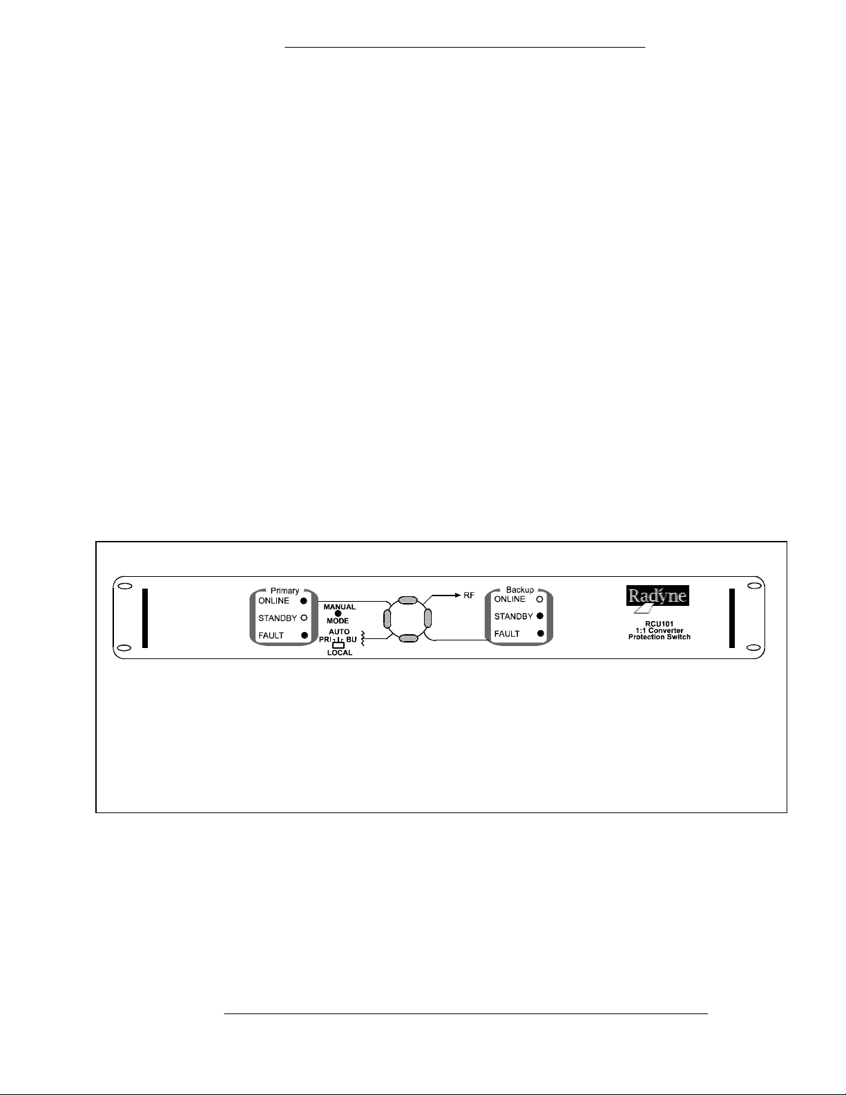
Figure 1-1. RCU101 1:1 Protection Switch Front Panel
TM055 - Rev. 2.2 Page 1-1
Page 9

Description SFC4200 C-Band Downconverter
Page 1-2 TM054 - Rev. 2.2
Page 10

RCU101 1:1 Protection Switch Installat i on
Section 2 - Installation
2.0 Installation Requirements
The RCU101
and requires 1 rack unit of mounting space (1.75 inches) vertically, and 17-inches of depth.
Includi ng cabli ng, a m inim um of 20-i nches of rack depth i s required. T he unit can be placed on
a table or suitable surfac e if required.
2.1 Unpacking
The RCU101 was carefully packaged to avoid damage and should arrive complete with the
following items for proper install ation:
is designed t o be i nstall ed within any standar d 19-inch equi pment cabinet or rack,
There are no user -serviceable parts or configurat ion sett ings located inside t he RCU101
chassis. There is a potential shock hazard internally at the power supply module. DO
NOT open the RCU101
⇒
CAUTION: Before init ially applying power to t he unit, it is a good idea to disconnect
the transmit output from the operating satellite ground station equipment. This is
especially tr ue if the current RCU101 c onfiguration sett ings ar e unknown, w her e inc or r ec t
setting could disrupt existing comm unic ations traffic.
1. RCU101 1:1 Protec tion Switc h
chassis under any cir c um s tances.
2. One cable set per paragraph 2.3.
3. Installation and O per ation Manual.
2.1.1 Removal and Assembly
If using a k nife or c utting bl ade to open the carton, exercise caution to ensure t hat the blade does
not ex tend i nto t he c arton, but onl y c uts the t ape holdi ng t he cart on cl osed. Caref ul l y unpac k the
unit and ensure that all of the above items are in the carton. The RCU101 is shipped fullyassembled and does not requir e r emoval of the covers for any pur pose in installation.
2.2 Mounting Considerations
When mounted in an equipment rack, adequate ventilation must be provided. The ambient
temperat ure in t he rack should be between 10° and 35° C, and hel d constant for best equipm ent
operation. The air available to the rack should be clean and r elativel y dr y .
2.3 Cabling
The RCU101 comes com plet e with all the cabl ing requi red to i nterf ace with two Upconvert ers or
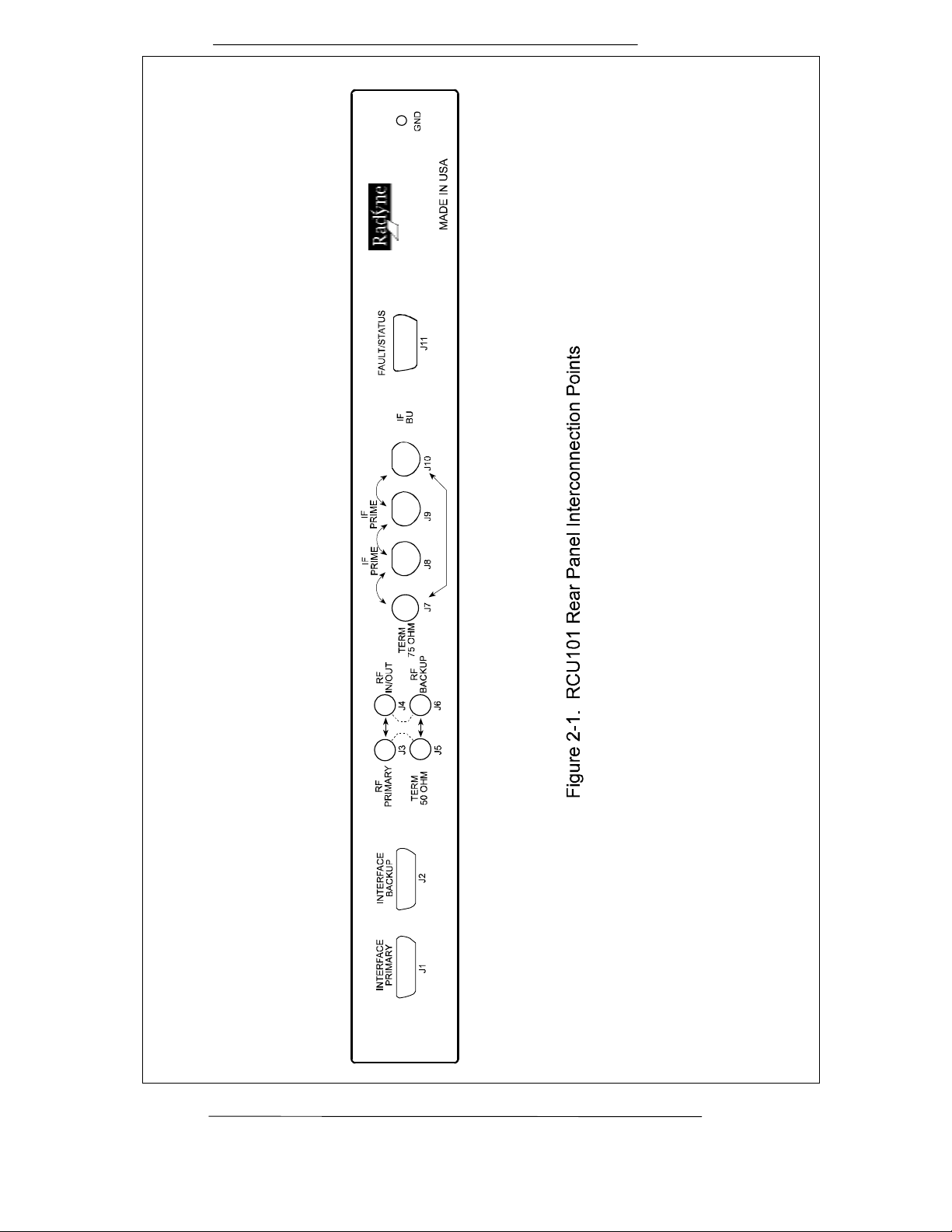
Downconverters. Refer to Figure 2-1 to become familiar with the rear panel connect ors on the
RCU101. Figure 2-2 shows a typical interconnection between two Upconverters and the
RCU101. The list of supplied cables is as follows:
Description QTY
P/N
CA/3291 RS485 Equipm ent Interface Cable 1
CA/3292 B/U Switch I nterfac e Cable 2
TM055 - Rev. 2.2 Page 2-1
Page 11
Installat i on RCU101 1:1 Protection Switch
Page 2-2 TM055 - Rev. 2.2
Page 12

RCU101 1:1 Protection Switch Installat i on
TM055 - Rev. 2.2
Page 2-3
Page 13

Installat i on RCU101 1:1 Protection Switch
CA/3293 RF Cable, 1:1 Switch 2
CA/1961-003 IF Cable, 1:1 Swit c h 2
Routing of the cabl es between the two conver ters and the switch i s depicted i n Figur e 2-2. Note
that the RF/IF cabling incl uded wi th the switch does not i nclude cables to other panels in the
rack.
2.4 Hardware Interfaces
Hardware interf aces between the onli ne and backup conv ert er and the switch equipment incl ude
the RF interf ace, I F int erface, Switch Interf ace, and Equi pment RS- 485 interf ace. In addit ion to
the abov e, the oper ator has access to all converter equipm ent i n the system i ncl udi ng the switch
via the operator RS - 232 interface on the converter.
2.4.1 Protectio n Switch Interface (P rimary & Backup) Co nnector (J1 & J2)
The protec ti on switch i nterface connect or i s a DB 15-pi n connect or that connec ts each converter
with the backup switch uni t. This c able i s not daisy-chai ned between conv erters but serv es as a
direct link for each conv erter i n the confi guration whether t hey are the prim ary conv erter or t he
backup unit. This interface f inds use in both the 1:1 and 1:N configuration type switches. The
pinout of the switch is as f ollows:
J1 B/U Switch Interface
J1 Pin# DB 15
J7
1 N.O Form-C contact summary fault normal ly open contact 1
5 N.C. Form-C contact summary fault nor mally closed contact 9
9 COM Form-C c ontact summary f ault com mon contact 2
Nomenclature Description Controller AS/3048
13 GND 10
2 +15V Or ’d Diode Or’d +15 Vdc fr om converter 3
6 FCB1 Fault Code bit 1 11
10 FCB2 Fault Code bit 2 4
14 FCB3 Fault Code bit 3 12
3 FCB4 Fault Code bit 4 5
7 IDB1 ID Bit 1 13
11 IDB2 ID Bit 2 6
15 IDB3 ID Bit 3 14
4 IDB4 ID Bit 4 7
8 INT O Interrupt 15
12 RMT 8
Page 2-4 TM055 - Rev. 2.2
Page 14

RCU101 1:1 Protection Switch Installat i on
The ID Bit s provide i nf orm at i on to t he converter that tell s the conv erter which slot (either pri m ary
or backup) the convert er is plugged int o. The addresses are as follows:
IDB3 IDB2 IDB1 Position
IDB4
1 0 1 0 Back up
1 0 1 1 Primary
2.4.2 Switch Fault/ S t at us Connector (J11)
The RCU101 Redundancy Control Unit contains a summar y Fault/ S tatus connector that is
available to the equipment operator for the purpose of moni toring the summary fault status of
both converters as well as the individual stat us of the converters. The pinouts of this 15-pin D
SUB connector ar e as follows:
J11 DB15
Description
1 Primary Converter Summary Fault Relay Com.
2 Primary Converter Summary Fault Relay N.C.
3 Primary Converter Summary Fault Relay N.O.
9 Backup Converter S ummary Fault Relay Com.
4 Backup Converter S ummary Fault Rel ay N.C.
5 Backup Converter Summary Fault Relay N.O.
10 Switch Online Status Com. (B active/A inactive)
11 Switch Online Status N.C. (Primary O nline) - c ontinuit y
12 Switch Online Status N.O. (Backup Online) - continuity
13 Remote Primary (Active Low)
14 Remote B ac k up ( A c tive Low)
6 Switch Summary Fault Relay Com. (Active on OK/Inactive on Fault)
7 Switch Summary Fault Relay N.C.
8 Switch Summary Fault Relay N.O.
15 Ground
The prim ary and backup summary f ault relay cont acts provide fault indic ations to flow through
the switch int o one common connect or. In additi on, the two Form-C summar y fault contacts on
the test f ault connector on t he rear of the RCU101 prov ide a Form -C closure to indi cate which
conver ter is presently online. Cont inuity of these contact closures im plies online status f or the
indicat ed conver ter.
2.4.3 RCU101 RF and IF Rear Panel Connectors
The following paragraphs describe the RF and IF connectors located on the rear panel of the
RCU101.
2.4.3.1 J3 RF Primary
The RF Primary connector goes to the RF port of the primary converter. This connection is
made via the supplied semi-rigid cable with the RCU101 system. If the primary converter is
TM055 - Rev. 2.2
Page 2-5
Page 15

Installat i on RCU101 1:1 Protection Switch
online, this port will be connected to the RF In/O ut port (J4).
2.4.3.2 J4 RF In/Out
The RF In/Out port is the user interface to the RCU101 protection switch system. This
connection is an SMA F -type. The conv ersion to the N-type c onnector should be made at the
rack interface panel. If the system requires interface to an N-connector cable, an SMA-to-N
adapter is recommended.
2.4.3.3 J5 RF Termi nation 50- Ohm
The 50-ohm RF term inat ion term inates the RF output of a redundant upc onv erter system or the
input of a redundant downconv erter system for the conv ert er that i s in standby or f ault ed mode.
By removi ng the termination, access to the RF port of the standby c onvert er c an be obtained.
2.4.3.4 J6 RF Backup
The RF Backup connect or is a ty pe SMA-F t hat routes the RF signal of the bac kup conv erter t o
the transf er switch in the RCU101. This connection is made v ia the supplied semi-rigid cable
assembly that is included with the RCU101.
2.4.3.5 J7 IF T erminatio n 75-Ohm
The IF Ter minat ion is a 75-Ohm BNC type term inati on for the I F port of the converter that is in
standby mode. By rem oving t he 75-O hm ter m inat i on, t he operator can gai n access to the IF port
of the converter that i s curr ently i n standby mode.
2.4.3.6 J8 IF Prime
This BNC-F connector goes to the IF connector of the primary converter. This connection is
made via the suppl ied IF cable assembly with the RCU101.
2.4.3.7 J9 IF In/Out
This BNC-F c onnec tor is the user IF interface to the redundant conv er ter system.
2.4.3.8 J10 IF Backup
The IF Backup BNC-F connector connects to the IF port of the backup converter. This
connection is made with the IF cable assembly supplied wit h the RCU101 System.
2.4.4 Interfaces Common to the Converters
The RS485 equipment int er face and the operator serial I/O i nterface found on the convert er
hardware both play a role in the operat ion of the switch and are included here for c ontinuit y . For
further infor mation, please ref er to the converter manual for more information on these two
interfaces.
2.4.5 Operator Serial I/O (J8 on Converter Rear Panel)
Through the Operator Serial Port, the operator can gain access to all of the cont r ol feat ur es of
the converter. This enables the remote operator to configure the switch, set the gain and
frequency of the convert er and interrogat e status of the converter.
The Operator Serial Port is a DB 9-pin femal e connector at t he rear of t he conver ter. Thi s port
provi des serial int erface that c an be configured as eit her a RS232, RS422 or RS485 int erface.
This port allows the user to remotely control all of the f eatures outlined in the Serial Protocol
(Appendix B). The serial port comes configured as an RS-232 Serial port for DCE unless
Page 2-6 TM055 - Rev. 2.2
Page 16

RCU101 1:1 Protection Switch Installat i on
indicat ed otherwise. The pi nout of t he D sub 9-pin socket connector conf igured for RS232 or
RS422/485 is as follows:
Operator Serial I/O Connector (Rear Panel)
J8 DB 9 Pi n#
RS232 RS422/485 AS/3048 J10
1 N/C RXData\ 1
2 TXData TXData 3
3 RXData RXData 5
4 DTR -- to pin 6 DTR -- to pin 6 7
5 GND Gnd 9
6 DSR -- to pin 4 DSR -- t o pin 4 2
7 RTS -- to Pin 8 RTS -- to Pin 8 4
8 CTS -- to pi n 7 CTS -- to pin 7 6
9 N/C TXData\ 8
NOTE: In order to obt ain these signal s at the output connector, the jum per conf igurat ion on the
AS/3048 Cont roll er PWB must hav e been perf ormed as outl ined i n Appendix C. A sum mary of
jumper selections is as follows:
Configuration JP4-1 JP4-2 JP4-3 JP4-4 JP4-5 JP4-6 JP3 JP5 JP6 JP7 JP8
RS232
RS422
RS485
485 1/2 DPLX
OUT OUT OUT OUT IN IN OUT OUT IN OUT OUT
IN IN IN IN OUT OUT OUT* OUT OUT OUT IN
IN IN IN IN OUT OUT OUT* OUT OUT OUT IN
IN OUT OUT IN OUT OUT OUT* IN OUT IN IN
*Receiv er term inations f or twisted pair RS422/485 can be optional ly term inated at 120 ohms by
installing JP3. Factory-supplied cables for multiple converter "daisy chain" operation are
terminated at the c able ends.
2.4.6 Up/Downconverter Equi pment RS485 Po rt ( J6 on Converter Rear P anel)
An equipment mul ti-drop, full-duplex, bi-directi onal RS485 Interface al lows communi c ation
between converters. Because the RS485 i nterfac e uses a master /slav e (talker/listener)
confi gur ation, t he c onvert er that is designated the backup converter will automatically be
TM055 - Rev. 2.2
Page 2-7
Page 17

Installat i on RCU101 1:1 Protection Switch
established as the m aster . Under normal RS485 protocol, the m aster will poll a specific slav e
by address and only then will the slav e unit respond. The swapping of Transmit Data and
Receive Data is accompli shed i n the inter- c onvert er cable as the hardware int er face i s i dentical
for al l converters.
J6 DB 9-Pin
Description 10 Pin AS/3048
1 GND 1
2 SRCLK 3
3 No Connect 5
4 TX Not 7
5 TX 9
6 SRDAT 2
7 No Connect 4
8 RX Not 6
9 RX 8
The signals on pins 2 and 6 of the DB9 connector are t he clock and data of the I-squared bus
which is an optional interface em ployed in t he 1:8 (RCU108) protection systems only .
Page 2-8 TM055 - Rev. 2.2
Page 18

RCU101 1:1 Protection Switch Operation
Section 3 - Operation
3.0 Definitions
The nomenclature used throughout this manual is meant t o impl y var ious roles that each ( up or down)
conver ter assumes depending upon the state of the convert er s and the settings of the protected
conver ter system. These descriptions are as follows:
A Protected Converter System consists of the pri mary converter , backup converter, and the
RCU101 switch and required interf ac e c ables.
The Primary Co nverter is the converter that is connected to the Primary P or t on the Switch.
The Backup Converter is the c onvert er that is connect ed to the Backup Port on the Switch
The Online Converter can be either t he pr imary or backup converter.
3.1 Operation
The 1:1 protection switch uni t provides automatic restoration f or one online converter . An RS485
equipment interface all ows the backup c onvert er to ‘learn’ the frequency and gain settings of the
primary converter. T he learning proc ess is initiated by the user, via the backup converter. By
entering the Utilities menu from the front panel of the backup conver ter, it will allow the user to initiate
the learning process. The backup converter will indicate whether the learning process was successful.
If the process was not successful, the conv erter will indicate the learning process f ailed. Refer to the
conver ter manual for more detai ls.
(MENU) for next menu
(ENTER) for Learn Mode
<ENTER>
Automatic Learning in Process Automatic Learning
Failed
Automatic Learning <MENU>
Successfully Completed Reason For
Failure
3.1 Switch Logic
The RCU101 uses the output of the Form - C r elay in t he c onvert er to determ ine what action t o take.
In the f ollowing descri ptions, it is assumed that the switch is in Auto mode and that t he other converter
is not faulted. (If the switc h were in Manual m ode, no switching would tak e place).
The Fault N.O logic level is derived from the normally open c ontact of the summar y fault Form-C
relay in the converter. T he c onverter, when clear of any and all faul ts, asserts the summary fault
relay to t he not faulted state and the contact is open. A fault in the converter, turning t he c onverter
off, failure of the converter power supply, or disconnecting the switch interfac e c able will cause the
relay to close. Upon detection of t his event, the switch will toggle cont r ol and data to the other
converter.
Once the fault in the faulted converter is cleared, the converter will reset the summary fault relay and
the contact will again be open. Upon detection of this event, t he swit c h will place the converter in
standby, so that i t can be placed onl ine in the event that the other c onvert er fai ls. The switch will not
automatically switch back to the original online c onverter.
The following truth table illustrates this switching logic. A ‘1’ in this table indicates that the
corresponding converter is faulted.
TM055 - Rev. 2.2 Page 3-1
Page 19

Operation RCU101 1:1 Protection Switch
Primary Backup Action
0 0 No action. W hoever was onli ne, stays online.
1 0 Backup converter is placed online.
0 1 Primary converter is placed online.
1 1 No action. W hoever was onli ne, stays online.
In addition to providi ng the switching l ogic, the RCU101 provides each conver ter with 4 ID bits that tell
the partic ular converter whether it is the primary or bac k up c onvert er . The ID bi ts are as follows:
ID Bits
Mean ing
1010 Backup
1011 Primary
3.2 Manual/Auto Mode Selection Switch
The Manual/A uto mode selection switch i s l oc ated on the fr ont of t he RCU101 and is used in the
following manner:
When the switch is placed to the far left (PRI), the primary converter is placed onli ne and will stay
online even if it fault s.
When the switch is placed to the far right (BU) , the backup converter is placed online and will stay
online even if it fault s.
When the switch is placed in the middle posit ion, it will automatically switch to the backup when a
fault is detected in the online conv erter.
If t he front panel switch is accidentall y left in the m anual mode, the RCU101 can be placed in the auto
mode rem otely by sending a M anual Command followed by an Auto Com mand to the c onvert er that
was deselected by the fr ont panel switch. ( S ee the applicable converter manual f or more details).
3.3 Switch LEDs
The are two sets of i dentical switch LEDs, one set for the prim ary converter and one for the backup
conver ter. Their meani ngs are the same.
Online LED - The O nline LED i ndicates that the corresponding converter has been pl ac ed
online by the switc h.
Standby LED - The Standby LE D indicates that the corresponding c onvert er is in Standby.
Fault LED - The Fault LED indicates that the corresponding converter is currently f aulted.
Manual LED - The MANUAL LED indicates that the converter has been m anually selec ted and will
stay there.
3.4 Troubleshooting and/or Replacing a Faulted Converter
Prior to testing or replacing a faulted convert er it is strongly recommended that the mode select ion
switch be set to manually select the converter t hat is currently onli ne. Once the faults on the fault ed
conver ter have been cleared (or the converter has been replaced) , the converter can be placed in t he
standby by moving the mode select ion switch back to the center, t hus placing the switch in auto
mode.
Note: If the switch i s l eft i n the mi ddle (auto) posit ion while tests are being perfor med on a converter
that is not fault ed, and the onli ne c onverter faults, the switch will automatically toggle control and data
Page 3-2 TM055 - Rev. 2.2
Page 20

RCU101 1:1 Protection Switch Operation
to the converter under test. This can result in unwanted operation when the converter under test is
not at the same frequency or gain levels as the online converter.
TM055 - Rev. 2.2
Page 3-3
Page 21

Operation RCU101 1:1 Protection Switch
Page 3-4 TM055 - Rev. 2.2
Page 22

RCU101 1:1 Protection Switch Operation
TM055 - Rev. 2.2
Page 3-5
Page 23

RCU101 1:1 Protection Switch Maintenance
Section 4 - Maintenance
4.0 Periodic Maintenance
The RCU101 requires no periodic field maintenanc e pr oc edur es. The unit contains no
adjustment s. S hould a unit be suspected of a defect in field operations after all interface signals
are ver ified, the proper pr oc edure is to replac e the unit wit h another known working unit. If this
does not cure the probl em, faulty cabling or power should be suspected.
A faul t in the operation of the RCU101 should become evi dent through an illogical LED
indicat ion on the front panel. For example, fail ur e of the RF transfer switch will become
immediately obvious when all four LEDs of t he gr aphical t r ansfer switch displ ay on the front
panel illuminate. In this case, the RCU101 logic has commanded the transfer switch to a certain
position. This will illuminate the new position but the relay remains stuck in the old position.
Verification of t he oper ation of the IF and RF transfer switches can be veri fied t hr ough a DC
continui ty check at the BNC and RF connector s at the rear of the RCU101. The RF and I F cables
will need to be removed t o perform this test. Failur e of eit her the IF or RF transfer switch c an be
verified by checki ng the voltage to t he c oils on either relay assembly . The IF transfer switch coil
should have 4.5 Vdc and the RF transfer switch Coil should have 14.0 Vdc ac ross the coil (not to
ground). If a fault in either the RF or IF transfer switch m odule is suspected, these assemblies
can be changed in the field.
TM055 - Rev. 2.2 Page 4-1
Page 24

Maintenance RCU101 1:1 Protection Switch
4-2 TM055 - Rev. 2.2
TM055 - Rev. 2.2 Page 5-1
Page 25

Page 26

RCU101 1:1 Protection Switch Specifications
Appendix A
Technical Specifications
Remote Monitor and Control (via Backup or Online Converter front panel or serial por t):
Rear Panel:
RF Ports: SMA -F QTY: 2
IF Ports: BNC-F QTY: 2
Converter Interface: DB15-F QTY: 1
Summary Status: DB15-F QTY: 1
Switch RF Specifications:
Swi t ched RF Port s:
Bandwidth: DC-18 GHz
Inserti on Loss: 0.4 dB (C-band) , 0.5 dB (Ku-band)
Impedance: 50 Ohms
VSWR: 1.5:1 Max.
Isolation: 70 dB min. (C- B and) , 60 dB min. (Ku-Band)
Switch IF Ports:
Bandwidth: 50 - 180 MHz
Inserti on Loss: 1.0 dB Max.
Impedance: 75 ohms
VSWR: 1.5:1 Max.
Isolation: 65 dB Min.
Front Panel Control & Indicators
Power, Onli ne, Of f-line, Manual B ackup, Faul t LEDs
Backup, Primary, Online converter selection
TM055 - Rev. 2.2 A-1
Page 27

RCU101 1:1 Protection Switch Serial Protocol
TM055 - Rev. 2.2 A-2
Page 28

- Appendix B RCU101 Block Diagram,
Configuration Drawings
and Schematics
TM055 - Rev. 2.2 B-1
Page 29

Figure B-1. Functional Block Diagram
TM055 - Rev. 2.2 B-2
Page 30

Figure B-2. Top Level Assembly
TM055 - Rev. 2.2 B-3
Page 31

Figure B-3. AS/3265 Front Panel Assembly
TM055 - Rev. 2.2 B-4
Page 32

Figure B-4. AS/3527 Switch Assembly
TM055 - Rev. 2.2 B-5
Page 33

Figure B-5. AS/3527 Switch Assembly
TM055 - Rev. 2.2 B-6
Page 34

Figure B-6. CA/4014 Cable Assembly
TM055 - Rev. 2.2 B-7
 Loading...