


ci0052 issue 2, 2014-01-09
SNTL150P-PCSUITE interface suite
Configuration and Monitoring software for
Sentinel 150P automatic switch mode battery chargers
Installation and Operation Manual
41 – 46 Railway Terrace, Nechells, Birmingham, B7 5NG, United Kingdom Web: www.computroniccontrols.com
For sales & support, contact: |
|
|
ENOVATION CONTROLS LTD. |
|
ENOVATION CONTROLS |
|
||
Church Road, Laverstock, |
|
5311 S 122nd East Avenue, |
Salisbury, SP1 1QZ, United Kingdom |
|
Tulsa, OK 74146, USA |
Phone: +44 1722 410055 |
|
Phone: +1 918 317 4100 |
Fax: +44 1722 410088 |
|
Fax: +1 918 317 4266 |
E-mail: sales@enovationcontrols.eu |
|
E-mail: sales@fwmurphy.com |
Web: www.computroniccontrols.com |
|
Web: www.fwmurphy.com |
www.fwmurphy.eu/computronic |
|
|
|
|
|

In order to consistently bring you the highest quality, full featured products, we reserve the right to change our specifications and designs at any time.
Please read the following information before installing.
BEFORE BEGINNING INSTALLATION OF THIS PRODUCT:
Read and follow all product safety and installation instructions.
Please contact your Computronic Controls or F W Murphy representative immediately if you have any questions.
SNTL150P-PCSUITE installation & operation |
ci0052 p2/28 issue 2 2014-01-09 |

Table of Contents
Table of Contents |
3 |
System requirements |
5 |
Installation Guide |
6 |
Getting Started |
7 |
Environment settings |
7 |
Connecting To Charger |
8 |
Using the Interface Suite |
9 |
Interface Suite Environment |
10 |
View Level Overview |
11 |
Active Charger Profile |
11 |
View Level Overview |
12 |
Time in AC failure |
12 |
Time Charging (>500mA) |
12 |
Time in Float Mode |
12 |
Battery Voltage Graph |
13 |
Charger Current Graph |
13 |
Engineer View Overview |
14 |
Engineer password |
14 |
Charger Profile |
14 |
Global Charger Settings |
15 |
Manager View Overview |
16 |
Manager password |
16 |
Charger Profiles |
16 |
Charger Settings |
16 |
Charger Identification |
16 |
Charge History |
16 |
From the Setup Editor screen, a full Setup configuration can be created, deleted or modified. To create a new
Setup enter required name in the Setup Name area and complete all details as required. |
17 |
|
SNTL150P Configurable Settings |
|
18 |
Charger Profiles |
|
18 |
Preset Charger Profiles |
|
18 |
Creating Custom Profiles |
|
19 |
Deleting Custom Profiles |
|
20 |
Adding Current SNTL150P Profile To Software Suite |
|
20 |
Applying Custom Profiles |
|
20 |
|
|
|
SNTL150P-PCSUITE installation & operation |
ci0052 p3/28 |
issue 2 2014-01-09 |

Battery Check Routine |
21 |
Setting Charger Current Limit |
22 |
Boost Drop Out Current |
22 |
Auto-Boost Period |
22 |
Digital Input Settings (where fitted) |
23 |
Alarm Settings (where fitted) |
24 |
Resolving Communication Errors |
25 |
Configuration of SNTL150-P via TTL |
26 |
In System Programming |
27 |
SNTL150P-PCSUITE installation & operation |
ci0052 p4/28 issue 2 2014-01-09 |

System requirements
The SNTL-PCSUITE is a PC-based software program for configuring and monitoring Sentinel 150P series battery chargers. Communication between the PC and Sentinel 150P is via a USB and TTL converter.
Minimum system requirements:
1.Sentinel 150P series battery charger
2.Personal Computer (PC):
Processor: x86 (32 bit), 1GHz
RAM: 1Gb
USB port
Display: minimum resolution 1024 x 768
Operating System: Windows 7, Windows Vista, Windows XP Professional or Windows XP Home with .NET framework 3.5 or higher
3.SNTL-PCSUITE software
4.USB / TTL converter recognised as COM port on Windows OS
5.TTL Data lead (connecting Sentinel to USB/TTL converter)
6.USB lead (connecting PC to USB/TTL converter)
Item 3 above (SNTL150P-PCSUITE software) is available on request, part number 42.70.3824: the software is supplied by email attachment.
Item 3 is also available on CD-ROM, along with items 4 – 6, as a complete connection suite, model SNTL150P-PCCONN, part number 42.70.3825.
SNTL150P-PCSUITE installation & operation |
ci0052 p5/28 issue 2 2014-01-09 |

Installation Guide
1, Run the Sentinel 150-P Interface Suite.exe file to install software to PC
2, Select Next to continue through installation process.
3, After viewing license agreement, select YES to proceed
4, Select installation folder |
5, Select program folder and optional desktop icon |
6, Confirm installation by selecting Next |
7, Installation is complete, select Finish |
|
|
SNTL150P-PCSUITE installation & operation |
ci0052 p6/28 issue 2 2014-01-09 |
Getting Started
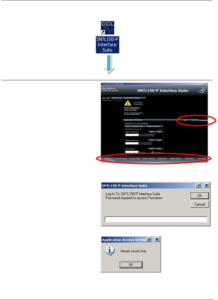
After installing SNTL150P interface suite on your PC, a desk top icon as shown below will be added. Select this to launch the SNTL150P interface suite
Environment settings
From Settings Screen, select environment from
Menu Bar and then select Log In To Interface
Suite
When asked for password, enter the supplied |
|
|
password to access the appropriate level. |
Menu Bar for Screen |
|
There are 3 modes of operation for the SNTL150P |
|
|
Interface Suite |
|
|
|
Basic View Level |
|
|
Engineer Level |
|
|
Manager Level |
|
Screen Tab Control
See SNTL150P Interface Suite Environment settings section of this document for information on paramaters available within each log in level.
Should an incorrect password be entered then the system will state the following:
And limit access to View Level only
SNTL150P-PCSUITE installation & operation |
ci0052 p7/28 issue 2 2014-01-09 |

Connecting To Charger
Once connected to charger and SNTL150P has either DC or AC power, select Scan For Devices to initiate scan.
Upon successful detection of the SNTL150P the software suite will automatically connect and start communicating
See resolving communication errors section (- page 25) of this document should you have problems connecting to the SNTL150P
Once communication is established with the unit, the Top & Side Status windows and indications will become active and reflect the SNTL150P’s current condition
Top Status Window
In addition to information about voltage, output current and SNTL150P model information, the Top Status Window provides information regarding its charging state. Battery (°C) Thermometer - will indicate SNTL150P detected battery temperature should a remote temperature compensation lead be connected. (Temperature is shown in °C)
Boost Status – Will indicate if SNTL150P needs to enter its boost cycle. Indicates if Waiting to Start, Active or Completed. Once SNTL150P terminal voltage has increased above boost initiate voltage, then this will become green. Commissioning Charge – When SNTL150P is first powered up, it will automatically enter a prolonged boost extension period, factory set to 6 hours, once complete this will become green and be marked as complete.
Input Status (if option fitted) – Shows indication of SNTL150Ps digital input Output Status – Shows indication of SNTL150P self-resetting output protection circuit
Relay Status (if option fitted) – Shows Fault Relay Status
Side Status Window
The firmware revision installed in the SNTL150P is displayed along with option to update, Consult updating firmware section within this document.
The side status window will indicate information about timers on the SNTL150P.
Power On Time – Duration that the SNTL150P has been powered (AC or DC) Time Left in Active State - How long the SNTL150P has remaining in its current state.
Time Until Battery Check - How long before next Battery Check is performed.
P.O.S.T. Timer / Boost Initiate Timer -
Time (counting down from 30s) until boost is initiated if battery measured voltage is below the boost initiate set point or the 6 second POST timer performed on initial power up or after a Connection Fault
Alarm Hold Off’s – Low, High and Charge Fail alarms are held off for 2 minutes, should the fault still be present at the end of the hold timer then an alarm will be indicated.
SNTL150P-PCSUITE installation & operation |
ci0052 p8/28 issue 2 2014-01-09 |
Using the Interface Suite
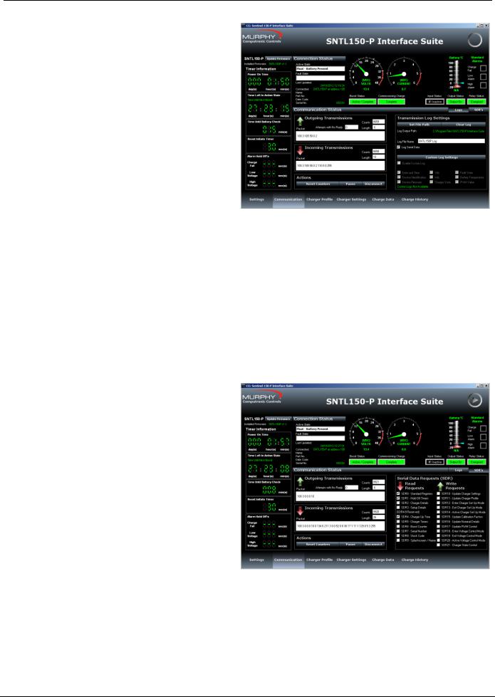
The Communication Screen
This screen shows Incoming and Outgoing
Transmissions between the PC and SNTL150P.
Reset Counters – Allows the monitored counts to be reset on the PC software
Pause – Allows the connections to be paused, ceasing all communications with charger until Continue is selected
To terminate connections with SNTL150P, select Disconnect from the Actions to ensure the Port is correctly closed.
Warning! Failure to do so before physically disconnecting from the SNTL150P may cause interrupt damage to the SNTL150P requiring a full AC/DC reset before normal operation can continue.
Transmission Log
SNTL150P Interface Suite can log all serial transmissions. These log files can then be loaded into the Charge Data Screen.
Set File Path - The File Path of stored log can be selected, default is same path as installed interface suite
Clear Log – Delete the log if already present
Log File Name – Enter a name for the log (default is SNTL150P Log)
Note: Custom Logs can be configured to record specific data in a csv file (TAB separated), under the directory selected as above.
The SDR (Serial Data Request) option shows messages queued waiting for action by software suite.
SNTL150P-PCSUITE installation & operation |
ci0052 p9/28 issue 2 2014-01-09 |
 Loading...