

Page 1
/$
/$
Uss
U
err
e
M
M
a
a
n
n
u
u
all
a
001
Page 2
SSaaffeettyy IInnffoorrmmaattiioonn
A. Never remove any printer cover except to install a printer accessory and as expressly
described in this manual.
B. Please store the printer covers in a safe place. The covers must be reinstalled if you decide to
remove any printer accessory.
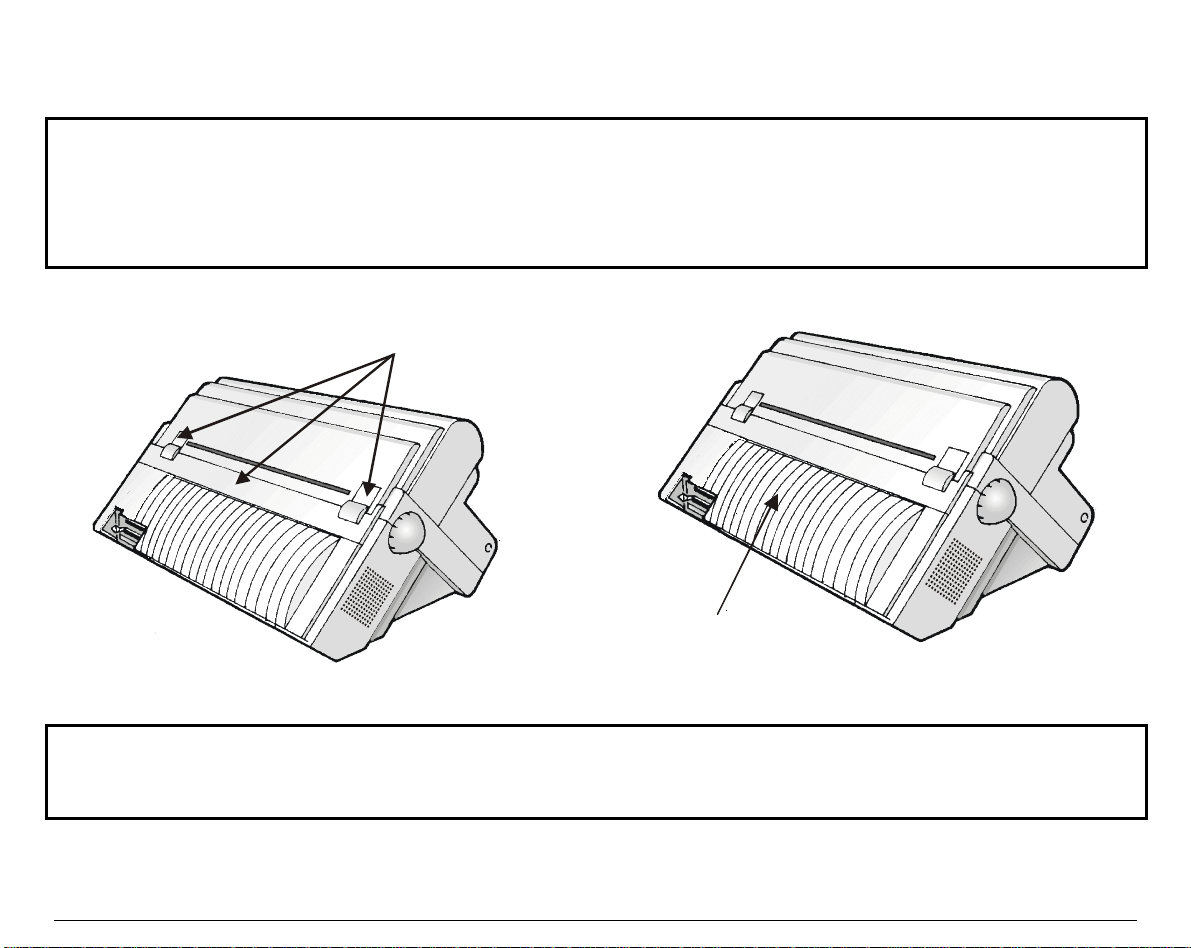
The following areas of the printer should be covered for safety reasons:
Pull Tractor Mechanism Covers
Large R ear C over
The above openings must always be protected with their cover when the corresponding option is
not installed. Do not touch inside the opening and do not insert any object into these openings or
into the gears.
ii
Page 3

TTaabbllee ooff CCoonntteenntts
Safety Information .............................................................................. ii
Table of Contents.............................................................................. iii
Getting to Know Your Printer..............................................................1
Printer Features............................................................................................1
Unpacking Your Printer...............................................................................2
Printer Parts..................................................................................................3
Front View................................................................................................3
Rear View..................................................................................................4
Setting Up Your Printer.......................................................................5
Choosing a Suita ble Loca tion.......................................................................5
Printer Assembly..........................................................................................6
Removal of the Ship ment Locks.............................................................6
Ribbon Cartridg e Inst all ati on.................................................................7
Host Computer Connection........................................................................13
Software Driver Selecti on..........................................................................15
Power Connection.......................................................................................16
Selecting the Displa y Lang uage................................................................18
Operator Panel Presentation.............................................................19
The Display..................................................................................................20
LCD Display Mes sages..........................................................................23
The Indicators..............................................................................................26
The State Indicators..............................................................................27
The Paper Path Indicat ors....................................................................28
The Buttons.................................................................................................29
Paper Handling..................................................................................38
Paper Paths.................................................................................................38
How to Select a Paper Path.......................................................................39
Using Set-Up Mode................................................................................39
Using the Operator Panel.....................................................................40
Paper Specificati ons....................................................................................41
Fanfold Paper.........................................................................................41
Print Area...............................................................................................42
Paper Thickness.....................................................................................44
Fanfold Paper Loadi ng...............................................................................45
Loading Paper Using t he Front1 Tra ctor............................................45
Parking the Paper.......................................................................................50
Resetting Paper Positi on.......................................................................51
Printing on Adhesive Lab els......................................................................52
Moving the Paper...................................................................................53
Advancing the Pap er for Teari ng-of f....................................................54
Operating your Printer.......................................................................56
s
Using Macros.............................................................................................. 56
About Macros.........................................................................................56
Switching between Ma cros................................................................... 57
Selecting Print Features............................................................................58
Selecting the Font..................................................................................59
Selecting the Pitch.................................................................................60
Holding a Print Task..................................................................................61
Reducing the Print Noise Lev el................................................................61
Recovering from a Fault Sta te..................................................................62
Recovering from a Paper out Fault......................................................62
Recovering from other Faults...............................................................62
Printing............................................................................................... 63
Print Area Definiti on..................................................................................63
Print Area Definition.............................................................................64
Printing on Multipa rt Form......................................................................66
Adapting to Pap er Thickness...............................................................66
Hints on Printer Settings for Pap er Thickness..................................67
Managing Blan k Pages.............................................................................. 68
Printing on Pre-printed Forms ..................................................................68
Adjusting the Top of Form from th e Opera tor Pa nel.........................69
Configuring Your Printer...................................................................70
What is Configuration?..............................................................................70
The Configuration Structure.....................................................................71
Display Graphi c Conventi ons...............................................................72
The Different Types of Sel ectabl e Va lues...........................................72
Configuration Quick Ref erence............................................................ 73
How to configure your Printer...................................................................83
Reaching, Selecting, Saving a Confi gurati on Valu e...........................83
Printing the Printer Config uration......................................................86
Tips for Configuring..............................................................................86
How to manage your Configurati on......................................................... 88
Saving a Configurat ion.........................................................................88
Restoring a Macro..................................................................................89
Restoring all Macros..............................................................................89
Recalling the Factory Configuration....................................................89
Setting the Printer Inst all ation.................................................................90
LCD Language.......................................................................................90
Error Buzzer...........................................................................................90
Ribbon Type...........................................................................................91
Paper Path at Power-On.......................................................................91
Tractor Jam Sensor............................................................................... 91
Page 4

Setting the Communication I nterfa ce.......................................................92
Interface Type.........................................................................................92
Interface Time-out.................................................................................92
Input Buffer Si ze....................................................................................93
Setting the Parallel I nterfa ce................................................................93
Setting the Serial In terfa ce...................................................................95
Setting the User Access Au thoriz ati on................................................98
Customizing Macros..........................................................................99
How to Customize a Ma cro........................................................................99
Selecting the Protocol.................................................................................99
Setting the Publishing S tyle....................................................................101
Font .......................................................................................................101
Quality Level........................................................................................101
Vertical Pitch........................................................................................102
Setting the Page Layout...........................................................................103
Form Length.........................................................................................103
Left Margin...........................................................................................104
Form Width..........................................................................................104
Top Margin...........................................................................................104
Bottom Margin.....................................................................................105
Top of Form...........................................................................................105
Selecting the Paper Path..........................................................................105
Setting the Printing Mod es......................................................................106
Print Direction......................................................................................106
Line Mode.............................................................................................107
Blank Pages..........................................................................................107
Print Impact.........................................................................................108
Print Gap..............................................................................................109
Automatic Gap Of fset..........................................................................110
Perforation Anti-jam............................................................................111
Setting the Tear/View M ode...............................................................111
Paper Movements According t o Tear/Vi ew Mod e.............................113
Paper Position Definiti on....................................................................116
Setting the DEC Mod e..............................................................................118
Horizontal Pitch...................................................................................118
G0 Character Set..................................................................................119
User Preference Character Set...........................................................120
Printer ID..............................................................................................121
Wrap or Truncate.................................................................................121
Disconnection on EOT.........................................................................122
Initial Report........................................................................................122
Automatic ANSWERBACK ................................................................123
ANSWERBACK on ENQ ....................................................................123
Configuring the IBM Mode......................................................................124
Horizontal Pitch...................................................................................124
IBM Character Set..............................................................................124
Code Page.............................................................................................125
IBM Double Height.............................................................................126
IBM AGM.............................................................................................126
Horizontal Pitch on COMPR ESS.......................................................126
Slashed Zero.........................................................................................127
Setting the EPSON Mod e...................................................................127
Horizontal Pitch...................................................................................127
National Character S et....................................................................... 128
Code Page.............................................................................................129
EPSON Character Set........................................................................130
Slashed Zero.........................................................................................130
Testing Your Printer ........................................................................131
Hex-Dump Printing..................................................................................133
Adjusting Your Printer....................................................................134
How to Adjust your Printer.....................................................................134
Adjusting the Bid irecti onal A lignment..................................................135
Adjusting the Positi on of th e First Pri ntab le Line................................136
Adjusting the Tear- off Pos ition...............................................................137
Printer Maintenance and Troubleshooting....................................138
Cleaning the Printer.................................................................................138
Replacing the Ri bbon C artri dge..............................................................139
Troubleshooting........................................................................................141
Options.............................................................................................149
The Front2 Push Tractor......................................................................... 149
Installing/Removing the Front2 Push Tractor.................................149
Loading Paper Using t he Front2 Tra ctor Op tion.............................152
The Rear Pull Tractor..............................................................................159
Installing the Rear Pull Tractor.........................................................159
Automatic Sheet Feeder ( ASF )............................................................... 164
Pedestals....................................................................................................165
Printer Specifications......................................................................166
Compliance Statements..................................................................172
FCC Compliance Sta tement ( USA )........................................................172
Compliance Statement ( Ca nad a)............................................................ 172
Compliance Statement ( Germa ny).........................................................172
Compliance Statement ( Europ e).............................................................173
Energy Star...............................................................................................173
International Compli ance........................................................................173
Trademark Acknowledgements
iv
Page 5

GGeettttiinngg ttoo KKnnooww YYoouurr PPrriinntteerr
PPrriinntteerr FFeeaattuurreess
• 24 Needle Print Head
• 136 columns
• 9070-LA printer: Draft printing at 700 cps, LQ printing at 133 cps
9060-LA printer: Draft printing at 600 cps, LQ printing at 116 cps
• The supported emulations are: IBM Proprinter XL24E, EPSON ESC/P and DEC PPL2
• High Resolution Graphics Printing (360 x 360 dots per inch)
• Multiple copies (1 original and 7 copies)
• Automatic paper path selection
• Easy operability via operator panel menu and S/W commands
• Optional Automatic Sheet Feeder (120 sheets capability) which handles cut sheets,
multicopies and envelopes, accepts up to two additional paper bins and includes paper stacker
• Optional Color Mechanism
• Usage of all specific features by means of the Specific Software Driver which is applicable to
the most popular S/W Packages
• Plug & Play capability for Windows 95/98/2000®
• Bi-directional IEEE 1284 parallel interface and RS232-C/422-A serial interface
1
Page 6
UUnnppaacckkiinngg YYoouurr PPrriinntteerr
g
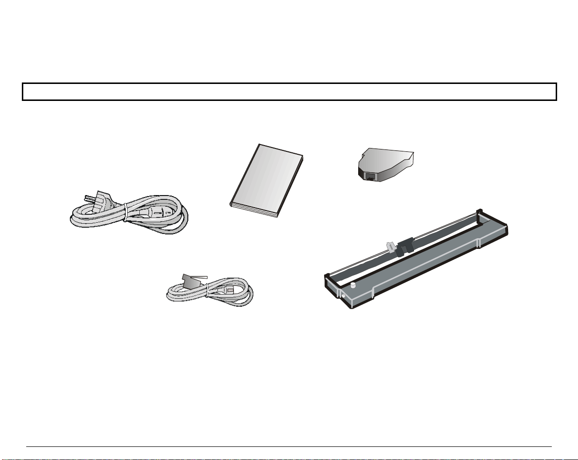
Together with the CD-ROM with this User Manual, the following items are included in the box:
Notify any damage to your supplier.
Power Cable
Serial Interface Adapter
Q uick Reference Guide
Ribbon Cartrid
Serial Interface Cable
2
e
Page 7
PPrriinntteerr PPaarrttss
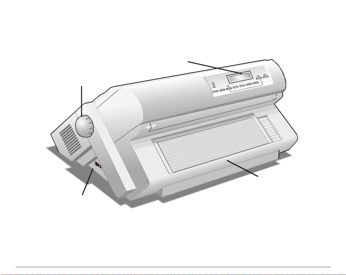
Front View
Paper Knob
Operator Panel
Power Switch
Push Tracto rs Cover
3
Page 8
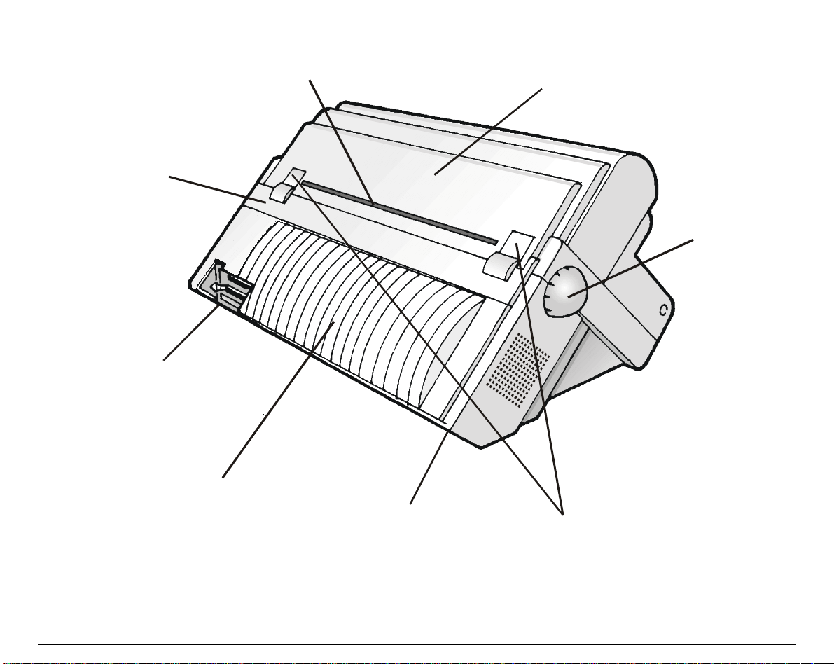
Rear View
Rear Tractor Cover
In te rface Co n n e c to r s
Re ar Paper Slot
Top Cover
Paper Knob
Large Rear Cover
Power Cable Connector
Rear Tractor Installation
Area C overs
4
Page 9
SSeettttiinngg UUpp YYoouurr PPrriinntteerr
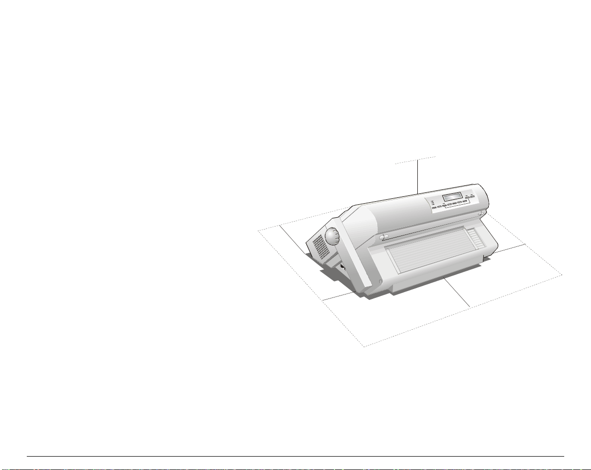
CChhoooossiinngg aa SSuuiittaabbllee LLooccaattiioonn
Consider the following points when you
choose the location for your printer:
• The distance between the printer and
the host computer must not exceed the
length of the interface cable;
• The location must be sturdy,
horizontal and stable;
• Your printer must not be exposed to
direct sunlight, extreme heat, cold,
P
r
i
n
t
e
r
P
r
dust or humidity (see "P
S
p
e
c
i
f
i
c
a
t
i
o
n
S
S
p
p
e
c
i
f
i
c
e
a
c
i
f
i
c
a
s
t
i
o
n
s
t
i
o
n
s
" later);
i
r
• The power outlet compatible must be
with the plug of the printer's power
cord.
There must be sufficient clearances on
all sides for easy operation. The
required space is shown in the figure:
n
t
e
r
n
t
e
r
i
80 cm
31.5 in.
1
0
0
3
9
c
.
m
4
i
n
m
c
0
2
n
i
9
.
7
1
0
3
0
9
c
.
4
m
i
m
c
0
2
n
i
9
.
7
n
5
Page 10
PPrriinntteerr AAsssseemmbbllyy
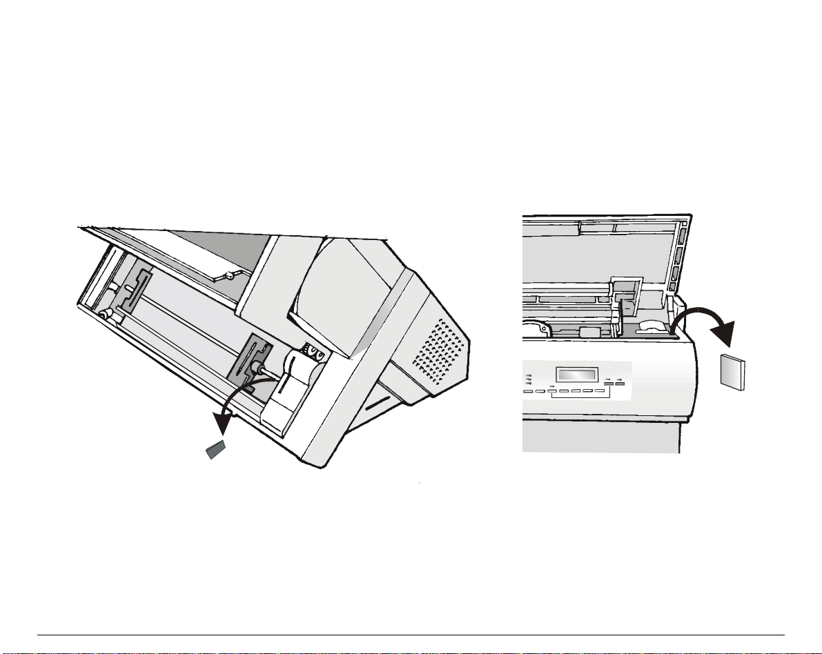
Removal of the Shipment Locks
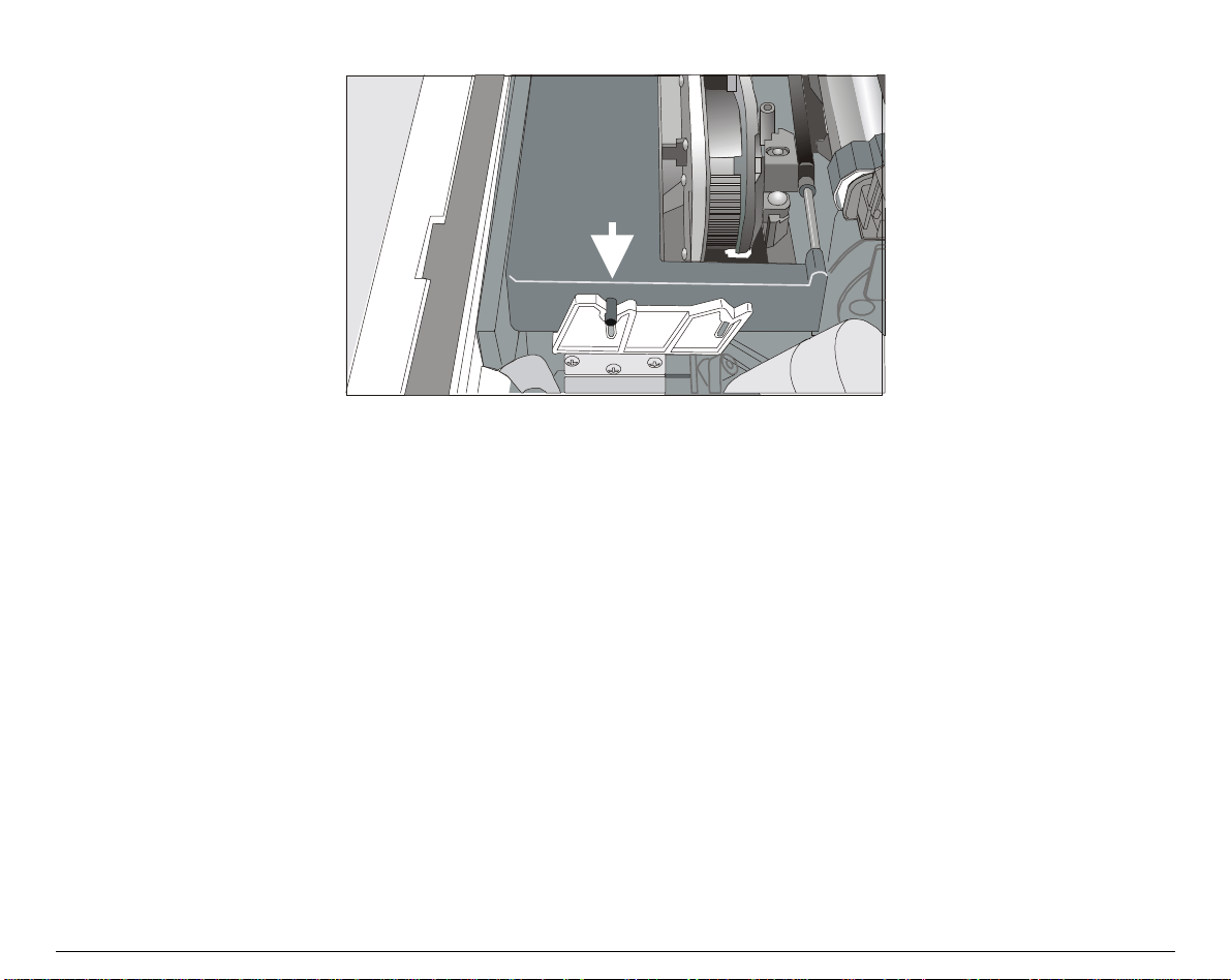
Open all the printer covers and make sure that you remove the two shipment locks from the
printer.
6
Page 11
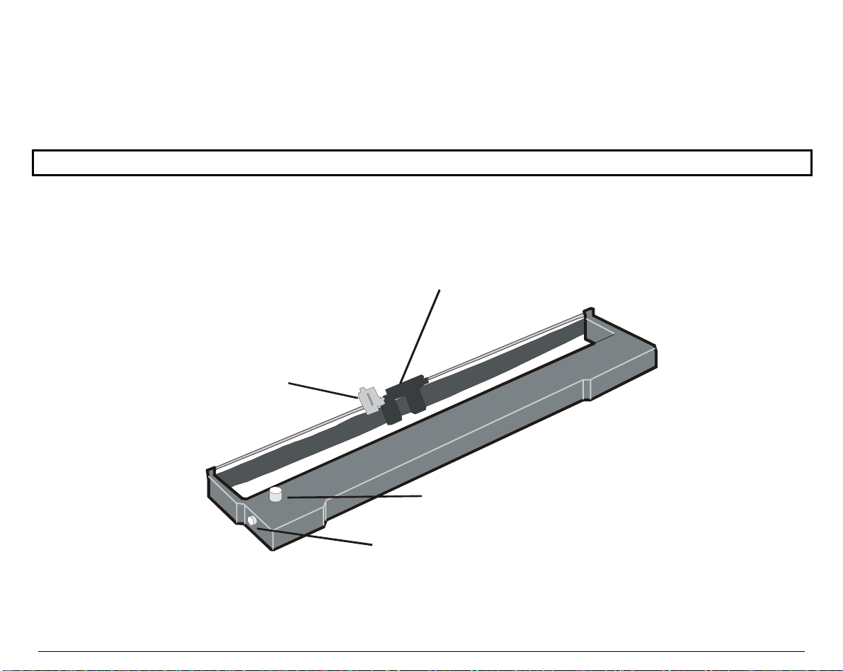
Ribbon Cartridge Installation
g
Two types of black ribbon cartridges are available for this printer, depending on whether the
color mechanism option is installed or not.
Make sure that you are using only CPG original consumables.
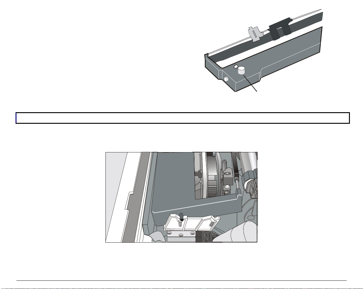
1. Make sure that the printer is turned off.
2. Find the ribbon cartridge among the accessories.
Ribbon guide
Ho lder for Color M ec hanism
Tension Knob
C a rtrid
e Pin
Long Life Black Ribbon Cartridge
7
Page 12
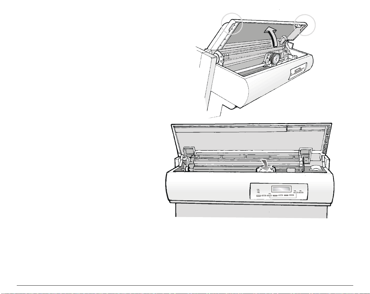
3. Open the top cover using the
small handles on either side of the
top cover.
4. Turn the printer on. The print
carriage prepares for ribbon
cartridge installation.
8
Page 13
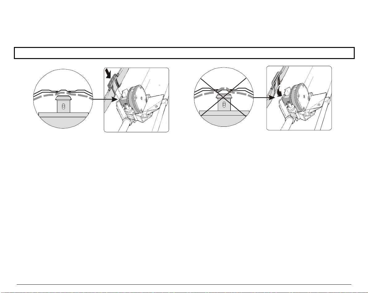
5. Before installing the ribbon cartridge turn
the ribbon winding knob in the arrow
direction (located on the cartridge) to take up
slack in the ribbon.
Ribbon Winding Kn o b
To avoid damage to the ribbon, do not turn the winding knob in the wrong direction.
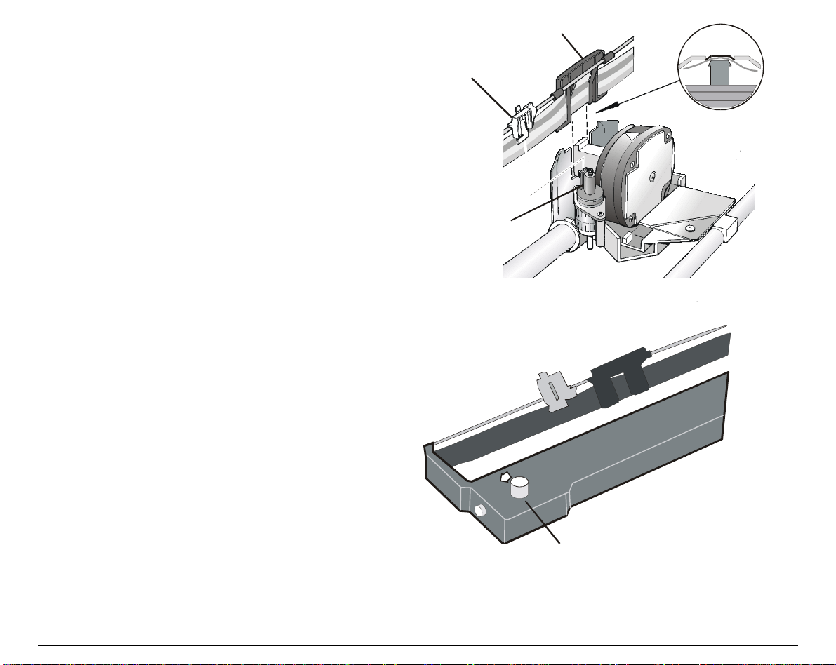
6. Align the cartridge pins with the locking grooves on the left and right cartridge supports.
9
Page 14
7. Slide and insert the ribbon guide between the print head and the ribbon guide mask holding it
perpendicular to the print head.
Make sure that the ribbon is inserted correctly between the print head and the print head mask.
2.
12
10
Page 15
8. Insert the white plastic holder onto the
color mechanism as shown in the
following figure.
9. Turn the ribbon winding knob in the
arrow direction (located on the
cartridge) to take up slack in the
ribbon.
Ribbon Guide
Ho lder for Color Me chanism
Color Me chanis m
Ribbon W inding Knob
11
Page 16
10. Push the cartridge down gently until it clips into place at the locking points on both sides.
11. Turn the ribbon winding knob again in the direction of the arrow to take up slack in the ribbon.
12. To ensure that the ribbon guide runs freely along the ribbon, manually move the print carriage
horizontally.
R
e
p
l
a
c
i
n
g
T
h
e
R
i
b
b
o
n
C
a
r
t
r
i
d
g
If the used ribbon cartridge needs to be replaced, see "R
R
e
p
l
a
c
i
n
g
T
h
e
R
i
b
b
o
n
C
a
r
e
p
l
a
c
i
n
g
T
h
e
R
i
b
b
o
n
t
C
a
r
e
r
i
d
g
t
e
r
i
d
g
e
", later
in this manual.
12
Page 17
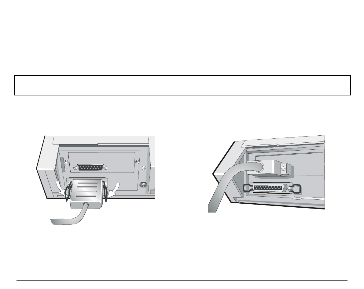
HHoosstt CCoommppuutteerr CCoonnnneeccttiioonn
This printer can be connected to the host computer via two available interfaces. The interface
connectors are located on the rear of the printer.
• A bidirectional IEEE1284 par allel interfac e
• A RS232C/422A serial interfac e
Before connecting the interface cable, make sure that the printer and t he host computer are
Insert the parallel interface cable into the parallel connec tor and fasten it by mean s of the c lips.
Insert the serial interface cable into the serial connector, and fasten it by means of the two screws
(use the screwdriver).
turned OFF .
Parallel Interface
13
Serial Interface
Page 18
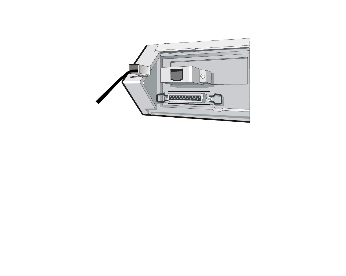
The interface cable with a 6 pin DECconnect type connector can be connected to the serial
interface connector by means of the serial interface adapter you received together with the
printer.
14
Page 19

SSooffttwwaarree DDrriivveerr SSeelleeccttiioonn
SSooffttwwaarree DDrriivveerr SSeelleeccttiioonn
At this point it is necessary to configure your printer for your application package. The installation
procedures depend upon the host environment.
Follow the instructions in the readme file you find on the CD-ROM .
In a WINDOWS 95/98/2000/XP/NT4.0/Millennium® environment the printer supports the Plug &
Play feature.
The printer drivers of all Compuprint printers can be found at the Internet Address
h
t
t
p
:
/
/
w
w
w
.
c
p
g
-
i
.
n
e
h
t
t
p
:
/
/
w
w
w
.
c
h
t
t
p
:
/
/
w
w
w
p
.
c
p
t
g
-
i
.
n
e
t
g
-
i
.
n
e
t
15
Page 20
PPoowweerr CCoonnnneeccttiioonn
The power outlet must be compatible with the plug of the printer's power cord.
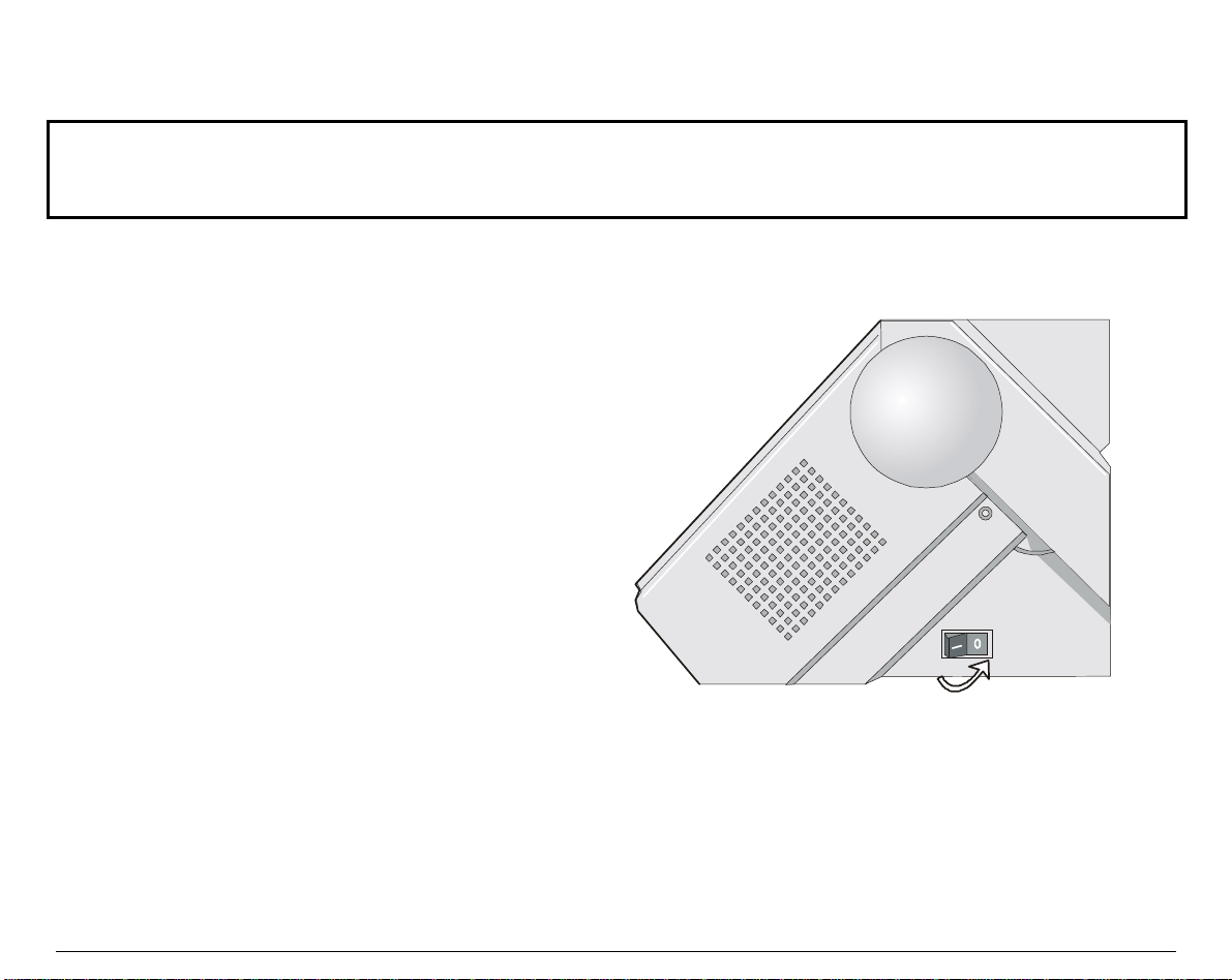
1. Make sure the power outlet is near the printer location and easily accessible.
2. Make sure that the power switch is in 0
position (OFF).
Always use a grounded outlet.
16
Page 21
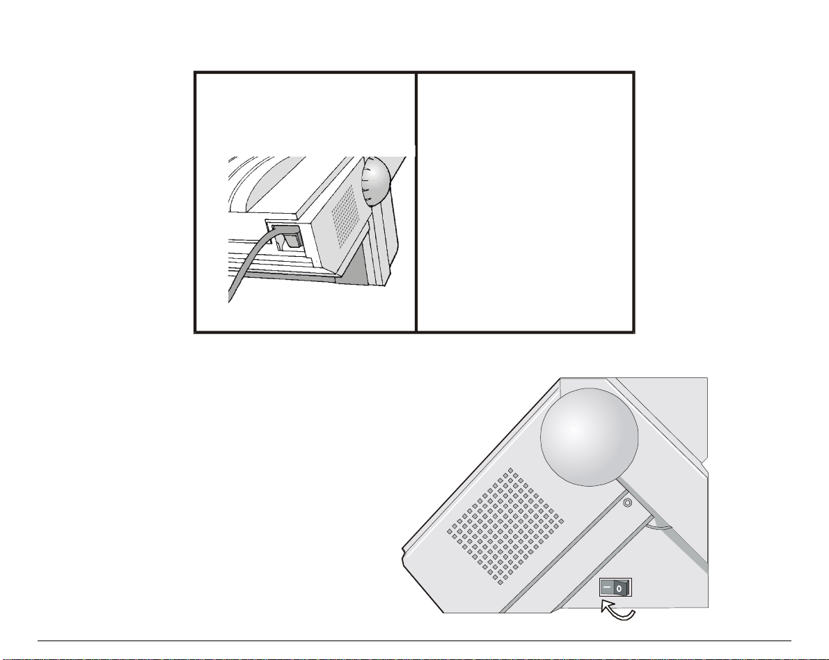
3. Insert the power cable plug into the printer connector and the other power cable end into a
convenient outlet (the figure shows the European version).
12
4. If you need to turn the printer on, press the
power switch in the I position (ON).
17
Page 22

SSeelleeccttiinngg tthhee DDiissppllaayy LLaanngguuaaggee
The display messages for this pri nter can be di splayed i n five different lang uages: Engli sh (Default),
French, German, Italian and Spanish. To select the language, that you prefer, pr oceed as follows:
1. Press the
The message "MACROS" appears on the display and the
Set-Up
button.
Set-Up
indicator blinks slowly.
2. Press the → button. The message "INSTALLATION" appears.
3. Press the ↓ button. The message "LANGUAGE" appears.
4. Press the ↓ button. The message "* English" appears. The * symbol indicates that English
is the current language for displaying the messages.
5. Select the language using the ← or the → buttons.
The different available languages appear on the display, each time you press one of these
buttons.
6. Once the desired language is displayed, confirm your choice by pressing the
Sel/Save
button.
The * symbol appears to confirm your choice.
7. Press the
button to exit Set-Up mode.
Exit
The message "Save config." appears, indicating that you are going to save your new
configuration.
• To permanently save your choice in the current M1 macro, press the
Sel/Save
button.
The new language selection will still be active at next power-on.
• To temporarily save your choice, press the
button.
Exit
The new language selection will be lost at next power-on. The previous language selection
will be active.
To cancel your modification and return to the previous configuration, press the
message "Restore Macro 1" appears. Press the
Sel/Save
18
button.
→ button. The
Page 23
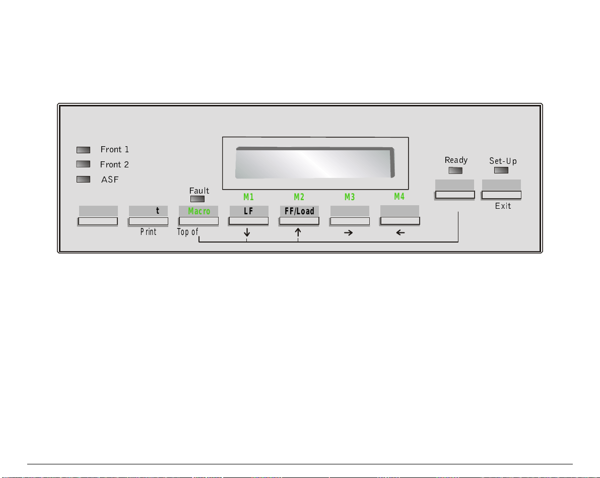
OOppeerraattoorr PPaanneell PPrreesseennttaattiioonn
The operator panel enables you to perform many of the printer functions including paper path
selections, font selection and the printer setup.
)URQW
)URQW
$6)
Path Quiet
)DXOW
Macro
M1 M2 M3
LF
FF/Load
Font Pitch
5HDG\
Pause
M4
Sel/Save
6HW8S
Set-Up
([LW
Park
Print Top of Form
The operator panel consists of:
• A 16 character display (Liquid Crystal Display)
• Six function mode indicators
• Nine function keys
19
Page 24
y
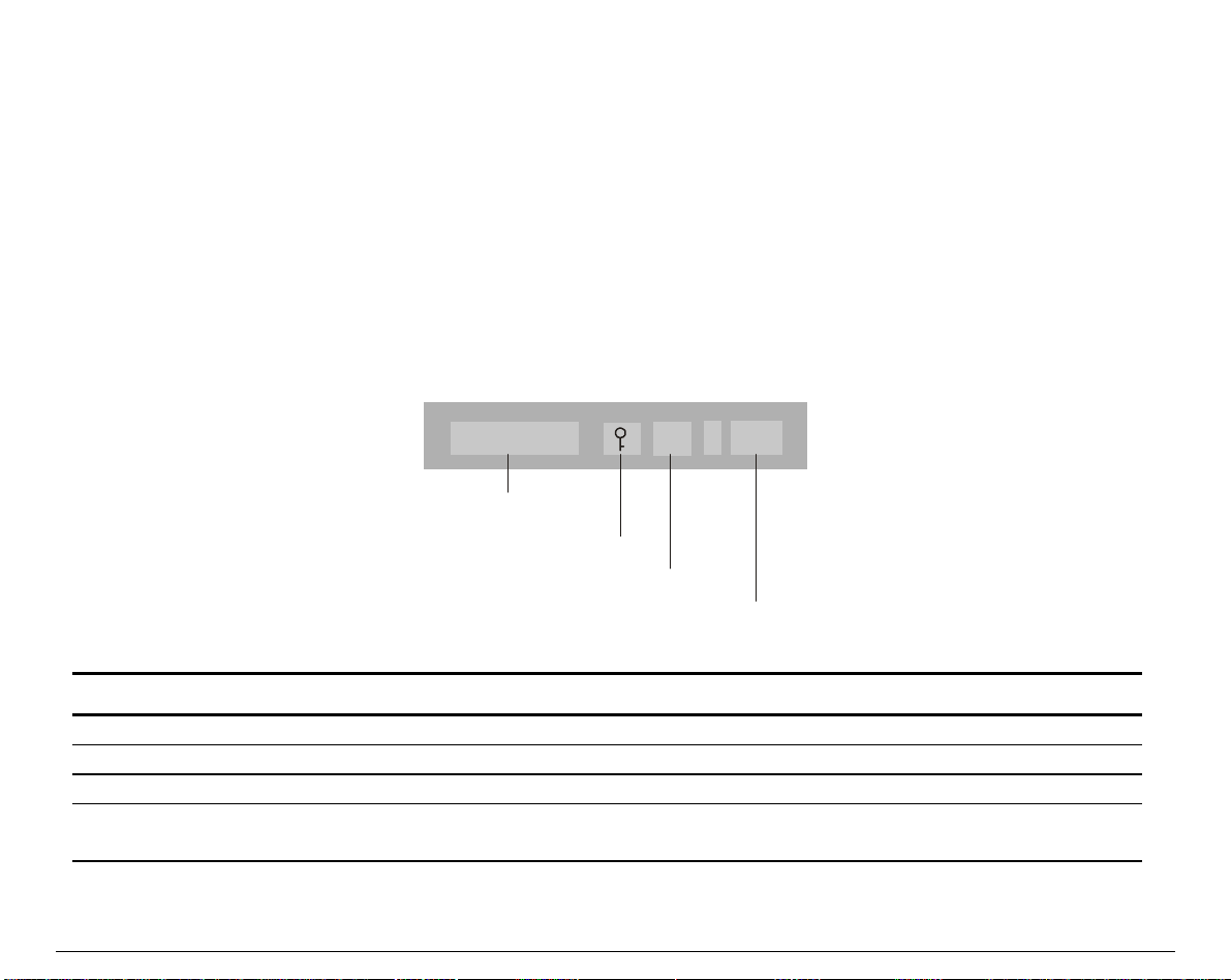
TThhee DDiissppllaayy
The display reads different types of messag es according to the printer state and the operating
mode.
The Basic Screen
The basic screen is displayed in Normal mode. It is overwritten with interactive messages, which
are described in a section below.
The display is div ided in four parts:
Ready M1 - Aut
Printer state
Lock s
Printer State Message Meaning
Ready
Busy
Pause
Quiet
Note: The
The printer is in Ready state.
The printer is in Busy state.
The printer is in Pause state.
The printer is in Quiet state.
Quiet
mbol
Macro
Protocol
message overwrites the other printer state messages.
20
Page 25
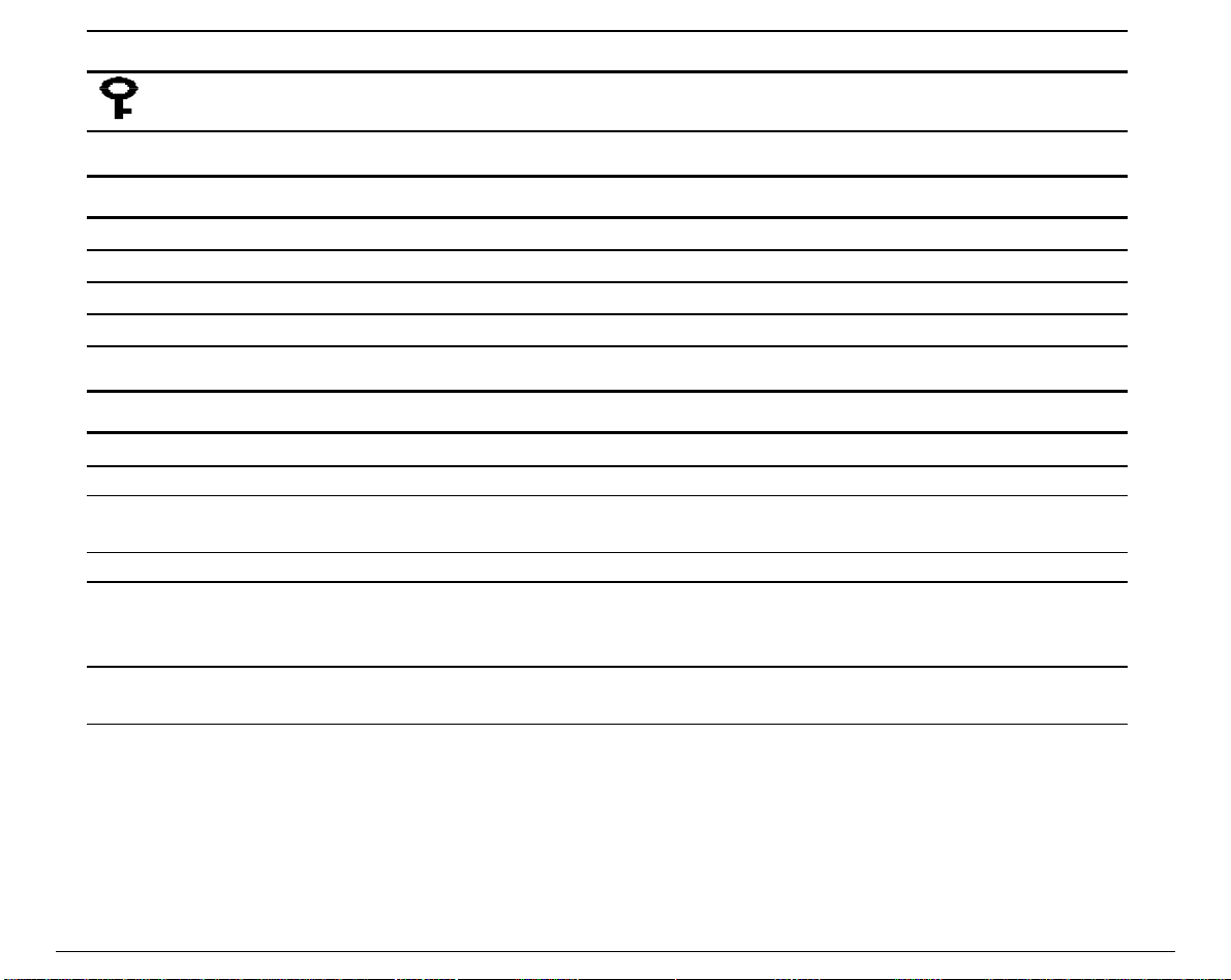
Lock Symbol Meaning
The use of a specific font or a specific horizontal pitch is forced (see "
F
o
n
t
/
P
i
t
c
h
S
c
r
e
e
F
o
n
t
/
P
i
t
c
h
F
o
n
t
/
P
S
i
t
c
h
n
c
r
e
e
S
n
c
r
e
").
e
n
Macro Message Meaning
M1
M2
M3
M4
The Macro 1 is selected.
The Macro 2 is selected.
The Macro 3 is selected.
The Macro 4 is selected.
Protocol Message Meaning
DEC
IPP
AGM
EP2
Aut
(blinking) The interface type is set to automatic. The printer switches to the protocol
Hex
Note: The
The DEC PPL2 protocol is selected.
The IBM Proprinter XL24E protocol is selected.
The Alternate Graphic Mode of the IBM Proprinter XL24E protocol is
selected.
The EPSON ESC/P protocol is selected.
you selected for each type of interface (serial or parallel) when receiving
data.
The Hexadecimal Dump has been selected.
Hex
message overwrites the other protocol messages.
T
h
e
T
h
e
T
h
e
21
Page 26
The Font/Pitch Screen
You access the Font/Pitch screen from the Basic screen after pressing the
Font
or the
Pitch
button.
The display is divided in two parts:
Draft
Font
10
Pitch
When you first access the Font/Pitch screen, the displ ay reads the following Factory setting for
the font and the pitch:
Font Messages Pitch Messages Common Meaning
SoftContrl. Soft. Software Control
Draft 10
Software Control means that the font and the pitch that are used by the printer are defined
through the commands of your software application. These messages appear with the font and
the pitch that will be used if the printer receives no software command.
22
Page 27
LCD Display Messages
Simple messages
User Instructions
Message Meaning
Adjust print gap
Load Push-Front1
Load Push-Front2
Load Push+Pull
Press Park
Remove paper
Select a Macro
Requires manual setting of the print gap, when exiting Set-Up after
having set the PRINT GAP Option to Manual adjust. See "
M
a
c
r
o
M
M
Displayed when paper out occurs on the corresponding path or when the
paper feeding device is not present.
This message is displayed when the USER ACCESS Option has been set to
Minimum and the only operator panel button to which the user is allowed
access after pressing the
Requires the loaded paper to be removed
Requires the user to press the button (M1, M2, M3 or M4) corresponding to
the Macro he wants to select.
s
a
c
r
o
s
a
c
r
" for more details.
o
s
Set-Up
button, is the
Park
button.
C
C
C
u
s
t
o
m
i
z
i
n
g
u
s
t
o
m
u
s
t
o
m
i
z
i
n
g
i
z
i
n
g
23
Page 28
Status Messages
Message Meaning
Push-Front1
Push-Front2
Top cover open
The Push-Front1 path is selected via the operator panel.
The Push-Front2 path is selected via the operator panel.
The top cover is open.
Operating Messages
Message Meaning
Loading paper...
Parking paper...
Printing test...
Processing...
Testing...
Starting-up...
The printer is loading paper in the current paper path.
The printer is parking the paper either because the
pressed, or because the paper path has been changed. The paper needs to be
parked in order to allow paper loading through the new path.
The printer is printing the output of one of the available printer tests.
The printer is processing data. Generic wait for operation end message.
The printer is executing the one of the available tests.
The printer is performing the bootstrap operations.
button has been
Park
24
Page 29
Rolling messages
Message Meaning
1.Check paper
2.Press Pause
1.Paper->Pull
2.Press Pause
1.Power-off
2.Push -> Front2
1.Tear-off paper
2.Park Paper
Carriage error
Check its moving
Comm. Failure
Check line
Data lost
Check interface
Print gap: Manual
Adjust print gap
These messages are displayed during the initialization of the printer,
when the Push+Pull paper path is selected. The user should check that
the paper has been correctly loaded and confirm by pressing the
button.
These messages are displayed during the paper loading procedure for the
Push+Pull paper path. The user should install the paper and confirm by
pressing the
Pause
button.
These messages are displayed when the Push-Front2 paper path is
selected and the tractor is not installed in the Front2 position.
Power the printer off and install the Push Front2 tractor option.
The printer was not able to park the paper, because it is too long. It
indicates that the paper should be torn-off and then parked again.
The print head carriage is not moving correctly. Open the top cover and
check if there is anything blocking the carriage.
Communication error. The DSR signal is not present on the serial
interface. Clear the error by pressing the
if the communication parameters for the serial interface are set correctly.
Data has been lost due to incorrect interface settings. Check the
interface parameters in the printer Set-Up.
Displayed when exiting from the printer Set-Up and the PRINT GAP
Option has been set to Manual adjust. See "
more details.
Pause
C
C
C
Pause
button twice, then check
u
s
t
o
m
i
z
i
n
g
M
a
c
r
o
u
s
t
o
m
i
z
i
n
g
u
s
t
o
m
M
i
z
i
n
g
M
s
a
c
r
o
s
a
c
r
" for
o
s
25
Page 30
Message Meaning
Gap failure
Check print gap
Printer failure
Call Service
Push-Front1 jam
Check paper
Push-Front2 jam
Check paper
Ribbon blocked
Check ribbon
Displayed when an automatic gap adjustment error occurred. Power the
printer off and on again. If the error is not solved, call the Customer Service.
The printer is in an error condition that cannot be solved by the user. Call the
Customer Service.
A paper jam occurred in the Push-Front1 path. Remove and reinstall the
paper.
A paper jam occurred in the Push-Front2 path. Remove and reinstall the
paper.
The ribbon cartridge is blocked. Check the ribbon cartridge installation.
TThhee IInnddiiccaattoorrss
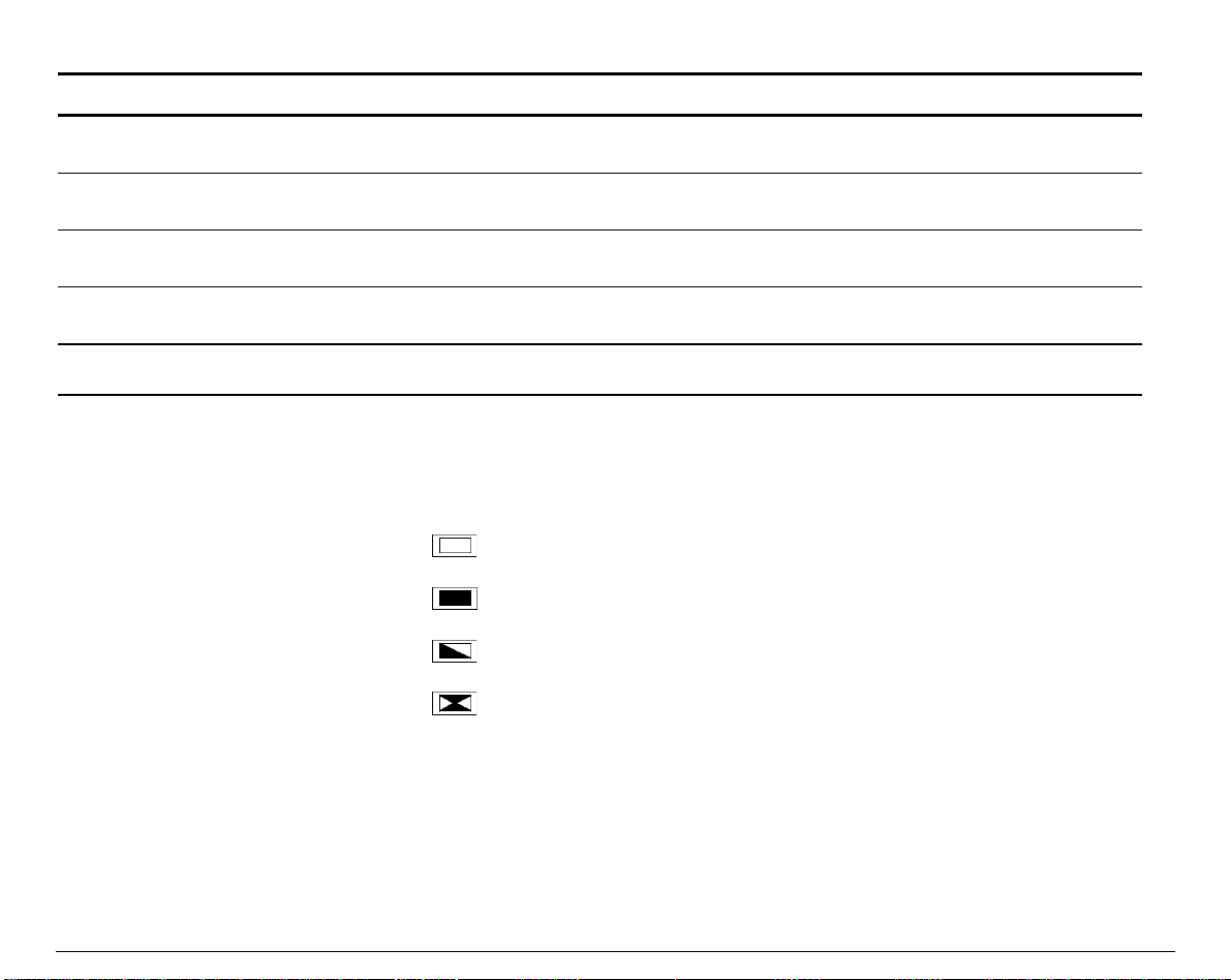
The following graphic conventions are used to describe the possible indicator be haviors:
Off
Lit
Flashing
Flashing rapidly
26
Page 31

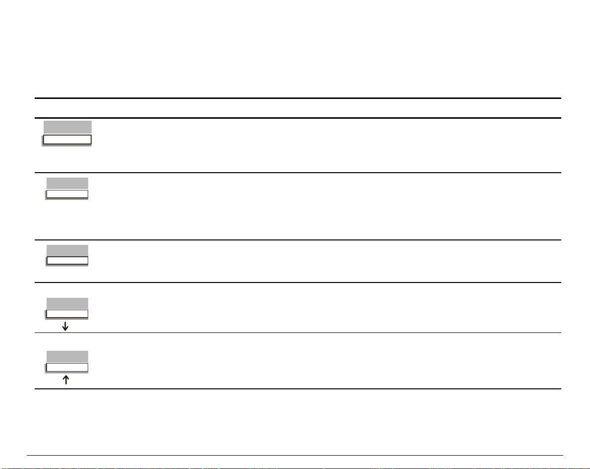
The State Indicators
The operator panel has three state indicators:
Indicator State Meaning
Ready
The printer is in Ready or Busy state.
Ready
The printer can receive printing information from the host.
Ready
Ready
The printer is in Pause state.
The printer cannot receive printing information from the host and the
current print tasks are put on hold.
Ready
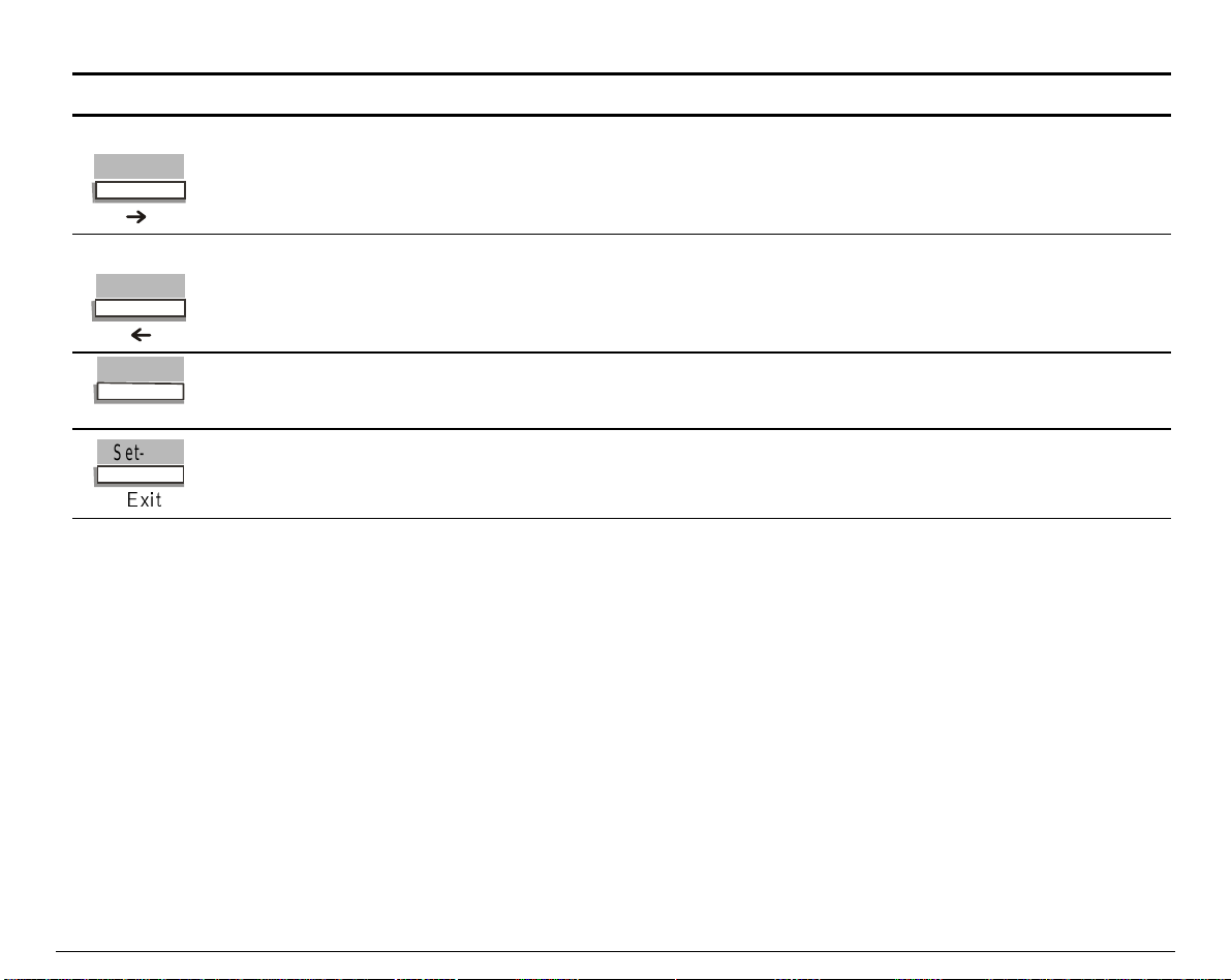
Set-Up
Set-Up
Fault
Fault
Ready
The printer is in Pause state, and there is still data in the input buffer.
Set-Up
The printer is in normal state.
Set-Up
The printer is in Set-Up state.
See the description of the paper path indicators below.
Fault
The printer is out of paper.
Fault
There is a fault such as cover open, paper jam, communication error, and
buffer overflow.
Fault
There is an internal diagnostic fault.
Fault
lit.
off.
blinking.
off.
blinking slowly.
lit.
blinking slowly.
blinking rapidly.
Fault, Ready
and
Set-Up
.
27
Page 32

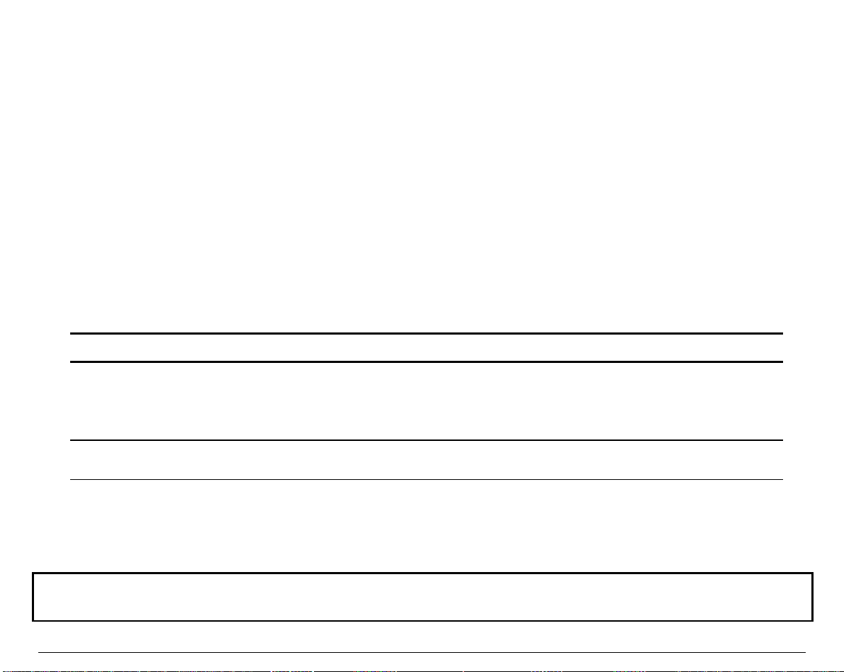
The Paper Path Indicators
The Paper Path indicators identi fy which Paper Path is selected. With this printer the paper
may be loaded through the following Paper Paths:
• Front1 Paper Path
• Front2 Paper Path
• ASF Paper Path
• Push-Pull Paper Path
Always remember to power-off the printer before mounting any new paper feeding device. This
allows the printer to automatically detect this device at power-on.
Indicator Status Meaning
)URQW
)URQW
$6)
)URQW
)URQW
$6)
Paper Path indicator lit.
The Paper Path corresponding to the lit indicator is selected. In this
example the Push-Front1 Paper Path is selected.
Paper Path indicator blinking.
The Paper Path corresponding to the blinking indicator is selected; but it is
out of paper. In this example the Push-Front1 Paper Path is out of paper.
28
Page 33

TThhee BBuuttttoonnss
y
)
)
The operator panel buttons are used to control the printer. Their function depends both on the
printer state and on the operating mode you have chosen. See the following section to know the
states and modes definitions.
The main function of each button is related to the Normal mode. This function is printed above
the button in a shaded rectangle.
The secondary functions concern the Set-Up mode, the Top of Form mode or any other specific
mode. These functions are printed outside the shaded rectangle. You access these secondary
functions after first pressing a button as follows:
you access the secondary functions printed in italic style after pressing the
–
you access the secondary functions printed in green after pressing the
–
Secondary F u n ctio n (Macro
Secondar
M a in Fu nc tion
F u n ctio n (Set-Up
Macro
Top of Form
29
M1
LF
Macro
Set-Up
button.
button
Page 34

The Operating States
The following definitions explain the printer operating states. A state is a specific situation
essentially characterized by the data flow interpretation and the physical config uration of the
printer transmitted through the different sensors. The first part of the display indicates the
T
h
e
D
i
s
p
l
a
T
h
e
current operating state (see the section "T
h
D
e
D
Throughout this User Manual, we refer to these definitions.
Operating State Definition
y
i
s
p
l
a
y
i
s
p
l
a
y
").
Ready
Busy
Pause
Fault
No data are to be printed
-
No fault is detected by the sensors
-
Data are to be printed (being printed or not)
-
No fault is detected by the sensors
-
Printing is put to hold
-
No fault is detected by the sensors
-
A fault is detected by the sensors
-
The printer buzzer sounds according to the Set-Up setting, and the
-
display reads a specific error message
30
Page 35

The Operating Modes
The following definitions explain the printer operating modes. An operating mode allows the
user to perform specific operations grouped according to a common functi on.
Some other features are also called modes, especially within the Set-Up options. The following
description concerns only the modes that affect how you use the printer, mainly by using the
button functions. Throughout this User Manual, we refer to these definitions.
Operating Modes Definition
Normal This is the basic operating mode of your printer, allowing you to perform all the
operations related to getting documents printed: printing, handling paper, selecting
fonts, managing the operating states, switching between your customized
configurations.
Quiet This is the same mode as Normal, except that printing is performed with a lower
noise level than in Normal mode.
Tear/View This mode is part of the Normal mode, since it defines the way the paper moves at
the end of each print task or when putting the task on hold (Pause state). For
example, you can make the paper automatically advance to the tear bar at the end of
the print task, or see the last printed line when you switch to Pause state.
Set-Up This mode mainly allows you to set-up your printer according to your operating
environment. You can also define 4 customized configurations depending on the
different kinds of jobs you have to manage.
Top of Form You can quickly access the Top of Form mode (abbreviated to ToF) from Normal
mode in order to modify the position of the first printable line.
Hex-Dump This is a special printing mode allowing you to check the proper functioning of your
application or your printer.
Adjustment This mode allows you to perfectly adjust your prin ter behav ior, in particu lar the
bidirectional alignment, the position of the first printable line and the alignment of
the paper perforation with the tear bar.
31
Page 36

The Function of the Buttons in Normal Mode
As explained previously, the function of the button mainly depends on the operating mode but is
also affected by the printer state. Normal mode gives you direct access to the followi ng button
functions:
Button Functions Purpose
Ready/Pause State Busy State Fault State
Paper Out Other Fault
Path
Park
Quiet
Print
Macro
Top of Form
Path
Quiet
Macro
To select one of the
available paper paths.
H
o
w
t
o
S
e
H
o
w
H
o
See "
P
a
P
a
P
a
To toggle between the
Quiet and the Normal
modes.
See "
N
o
N
o
N
o
To select one of the Macros
(access to the M1, M2, M3
and M4 button functions).
See "
w
p
e
r
P
p
i
a
e
r
P
p
i
a
e
r
P
a
R
e
d
u
R
e
d
u
R
e
d
u
s
e
L
e
v
s
e
L
e
i
v
s
e
L
e
v
U
s
i
n
g
U
s
i
n
g
U
s
i
n
l
t
o
S
e
t
g
l
t
o
S
e
l
h
t
h
t
h
".
c
i
n
g
t
c
i
n
g
t
c
i
n
g
t
e
l
e
l
e
l
".
M
a
c
r
M
a
c
r
M
a
c
e
c
t
a
e
c
t
a
e
c
t
a
h
e
P
r
i
n
h
e
h
e
o
s
o
s
r
o
s
t
P
r
i
n
P
r
i
n
".
Inactive Same as for
Ready/Pause
state.
Same as for
Ready/Pause
state.
t
t
Inactive Same as for
Same as for
Ready/Pause
state.
Ready/Pause
state.
Inactive
Inactive
Inactive
32
Page 37

Button Functions Purpose
Ready/Pause State Busy State Fault State
Paper Out Other Fault
M1
LF
M2
FF/Lo ad
M3
Font
LF
M1
FF/Load
M2
Font
M3
- To advance the paper
LF
one line at the current
vertical pitch.
M
o
v
i
n
g
t
h
e
P
a
p
e
M
o
v
i
n
g
t
M
o
See "
M1
U
U
U
"
FF/Load
v
- To select Macro 1.
s
i
n
g
M
s
i
n
g
M
s
i
n
g
M
- To advance the
h
i
n
g
t
h
a
c
r
o
s
a
c
r
o
s
a
c
r
o
s
e
e
".
r
P
a
p
e
r
P
a
p
e
r
".
See
paper. The paper moves
according to the settings of
the Tear/View mode.
M
o
v
i
n
g
t
h
e
P
a
p
e
M
o
v
i
n
g
t
h
e
M
o
v
i
See "
- To select Macro 2.
M2
U
s
i
n
U
s
i
n
U
s
i
"
- To force one of the
Font
n
g
M
a
c
g
M
a
n
c
g
M
a
g
t
h
e
r
o
s
r
o
s
c
r
o
s
".
available resident fonts.
S
e
l
e
c
t
i
n
g
P
S
e
l
e
c
t
S
e
l
e
c
See "
F
e
a
t
u
F
e
a
t
u
F
e
a
t
- To select Macro 3.
M3
U
s
i
n
U
s
i
n
U
s
i
n
"
t
r
e
s
r
e
s
u
r
e
s
".
g
M
a
c
g
M
a
c
g
M
a
r
i
n
g
P
r
i
n
g
P
r
o
s
r
o
s
c
r
o
s
".
r
P
a
p
e
r
P
a
p
e
r
".
See
i
n
t
i
n
t
r
i
n
t
See
Inactive Same as for
Inactive
Ready/Pause
state.
Inactive Same as for
Inactive
Ready/Pause
state.
Inactive Same as for
Inactive
Ready/Pause
state.
33
Page 38

Button Functions Purpose
Ready/Pause State Busy State Fault State
Paper Out Other Fault
M4
Pitch
Pause
Sel/Save
Set-Up
([LW
Pitch
M4
Pause
Set-Up
- To force one of the
Pitch
available resident pitch
S
e
l
e
c
S
e
l
e
c
S
e
l
e
values.
P
P
P
M4
U
U
U
"
To toggle between the
Pause and the Ready state.
The paper moves according
to the settings of the
Tear/View mode.
H
H
H
"
To access the Set-Up mode,
the corresponding button
functions and other specific
button functions (
See "
r
i
n
t
F
e
a
r
i
n
r
i
n
- To select Macro 4.
s
i
n
s
i
n
s
i
o
l
d
o
l
o
l
t
t
F
e
a
t
t
F
e
a
t
g
M
a
c
g
M
a
n
d
d
c
g
M
a
i
n
g
a
i
n
g
a
i
n
g
a
Print, Top of Form
T
h
e
F
See "
B
u
B
u
B
u
M
o
M
o
M
o
T
T
t
t
o
t
t
o
t
t
o
d
e
d
e
d
e
u
h
e
F
u
h
e
F
n
s
i
n
n
s
i
n
n
s
i
n
".
c
u
r
e
s
u
r
e
s
u
r
e
s
".
r
o
s
r
o
s
c
r
o
s
".
See
P
r
i
n
t
P
r
i
n
t
P
r
i
n
t
Park
).
n
c
t
i
o
n
c
t
i
o
u
n
c
t
i
o
S
e
t
-
U
S
e
t
-
U
S
e
t
-
U
t
i
n
g
t
i
n
g
t
i
n
g
See
T
a
s
k
T
a
s
k
T
a
s
k
,
n
o
f
t
n
o
f
t
n
o
f
t
p
p
p
Inactive Same as for
Ready/Pause
state.
Same as for
Ready/Pause
state.
".
Same as for
Ready/Pause
state.
h
e
h
e
h
e
Same as for
Ready/Pause
state.
Same as for
Ready/Pause
state.
Inactive
Clears the
fault and
returns to
previous
state.
Inactive
34
Page 39
The Function of the Buttons in Set-Up Mode
As explained previously, the function of the button mainly depends on the operating mode. The
printer state also affects the specific function purpose. By definition, you access the following
C
F
u
u
C
F
u
u
C
u
u
Set-Up
button.
o
n
f
i
g
u
r
a
t
i
o
o
n
f
i
g
u
o
n
f
i
g
u
n
r
a
t
i
o
n
r
a
t
i
o
n
".
o
r
m
f
r
o
m
t
h
e
O
p
e
r
a
t
o
r
P
a
n
e
o
r
m
f
r
o
m
t
h
e
O
p
e
r
a
t
o
r
F
o
r
m
f
r
o
m
t
h
e
O
p
e
r
P
r
i
n
t
e
r
P
r
P
r
P
r
P
r
P
r
r
i
n
t
e
r
r
i
n
t
".
e
r
r
i
n
t
e
r
r
i
n
t
e
r
r
i
n
t
".
e
r
r
a
t
o
r
P
P
l
a
n
e
l
a
n
e
l
".
button functions in Set-Up mode, which is after pressing the
Button Functions Purpose
Path
Park
Quiet
Print
Macro
Top of Form
M1
LF
M2
FF/Lo ad
Park
Print
Top of Form
↓
↑
With the Push-Front1 or Push-Front2 Paper Paths, to park the paper.
With the Push-Pull Paper Path advances the paper.
Note: This function is no longer active once you enter Set-Up.
P
a
p
e
r
H
a
n
d
l
i
n
See "
P
P
a
p
e
r
H
a
p
a
e
r
H
a
g
n
d
l
i
n
g
n
d
l
i
n
g
".
Pressing this button the printer prints the firmware version of your
printer and the list of set-up features of the four macros and their
associated values.
Note: This function is no longer active once you enter Set-Up.
P
r
i
n
t
i
n
g
t
h
e
P
r
i
n
t
e
r
See "
P
P
r
i
n
t
i
n
g
t
h
e
P
r
i
n
t
i
n
g
r
t
h
e
P
r
i
n
t
e
r
i
n
t
e
r
To access the Top of Form mode.
Note: This function is no longer active once you enter Set-Up.
A
d
j
u
s
t
i
n
g
t
h
e
T
o
p
o
f
See "
A
A
d
j
u
s
t
i
n
g
t
h
e
d
j
u
s
t
i
n
T
g
t
h
e
T
o
p
o
f
o
p
o
f
In Set-Up, to navigate downwards (through Functions, Options, Suboptions and Values).
H
o
w
t
o
C
o
n
f
i
g
u
r
e
Y
See "
H
H
o
w
t
o
C
o
n
f
i
g
o
w
t
o
C
u
o
n
f
i
g
o
r
e
Y
u
o
r
e
Y
o
In Set-Up, to navigate upwards (through Functions, Options, Suboptions and Values).
H
o
w
t
o
C
o
n
f
i
g
u
r
e
Y
See "
H
H
o
w
t
o
C
o
n
f
i
g
o
w
t
o
C
u
o
n
f
i
g
o
r
e
Y
u
o
r
e
Y
o
35
Page 40
Button Functions Purpose
M3
Font
M4
Pitch
Pause
Sel/Save
Set-Up
([LW
→
←
Sel/Save
Exit
In Set-Up, to navigate at the same level to the next item.
H
o
w
t
o
C
o
n
f
i
g
u
r
e
Y
o
u
r
P
r
i
n
t
e
See "
H
H
o
w
t
o
C
o
n
f
i
g
u
r
e
Y
o
u
r
o
w
t
o
C
o
n
f
i
g
u
r
e
Y
P
o
u
r
P
r
r
i
n
t
e
r
r
i
n
t
e
r
".
In the Set-Up structure, to navigate at the same level to the previous
item.
H
o
w
t
o
C
o
n
f
i
g
u
r
e
Y
o
u
r
P
r
i
n
t
e
See "
H
H
o
w
t
o
C
o
n
f
i
g
u
r
e
Y
o
u
r
o
w
t
o
C
o
n
f
i
g
u
r
e
Y
P
o
u
r
P
r
r
i
n
t
e
r
r
i
n
t
e
r
".
To select a Value and save the new Configuration.
H
o
w
t
o
C
o
n
f
i
g
u
r
e
Y
o
u
r
P
r
i
n
t
e
H
o
w
t
o
C
o
n
f
i
g
u
r
e
Y
o
u
r
H
o
w
t
o
C
o
n
f
i
g
u
r
e
See "
To exit Set-Up mode without saving the Values.
H
o
w
t
o
C
o
n
f
i
See "
H
H
o
w
t
o
w
t
o
o
C
C
g
o
n
f
i
g
o
n
f
i
Y
u
r
e
Y
u
r
e
Y
g
u
r
e
Y
P
o
u
r
P
o
u
r
P
o
u
r
P
o
u
r
P
r
r
i
n
t
e
r
r
i
n
t
e
r
".
r
i
n
t
e
r
r
i
n
t
e
r
r
i
n
t
e
r
".
36
Page 41

The Functions of the Buttons in Top of Form Mode
As explained previously, the function of the button mainly depends on the operating mode but is
also affected by the printer state. You access the following button functions in the Top of Form
mode that is after pressing the
The following table introduces only the buttons active in Top of Form mode.
Button Function Purpose
Top of Form
Macro
Top of Form
To reset the Top of Form Value to zero.
button.
Top of Form
M1
LF
M2
FF/Lo ad
Pause
Sel/Save
Set-Up
([LW
↓
↑
Sel/Save
Exit
To reduce the Top of Form Value (the paper moves backwards
accordingly).
A
d
j
u
s
t
i
n
g
t
h
e
T
o
p
o
f
F
o
r
m
f
r
o
m
t
h
e
O
p
e
r
a
t
o
r
P
a
n
e
P
P
P
P
P
P
P
P
P
P
P
l
a
n
e
l
a
n
e
l
" .
a
n
e
l
a
n
e
l
a
n
e
l
".
a
n
e
l
a
n
e
l
a
n
e
l
".
a
n
e
l
a
n
e
l
a
n
e
l
".
A
d
j
u
s
t
i
n
g
t
h
e
T
o
p
o
f
F
o
r
m
f
r
o
m
t
h
e
O
p
e
r
a
t
o
r
A
d
j
u
s
"
See
To increase the Top of Form Value (the paper moves forwards
accordingly).
A
A
A
"
See
To save the Top of Form Value and return to Normal mode.
A
A
A
"
See
To return to Normal mode without saving the Top of Form Value.
A
A
A
"
See
t
i
n
g
t
h
e
T
o
p
o
f
F
o
r
m
f
r
o
m
t
h
e
O
p
e
d
j
u
s
t
i
n
g
t
h
e
T
o
p
o
f
F
o
r
m
f
r
o
m
t
h
e
O
p
e
d
j
u
s
t
i
n
g
t
h
e
T
o
p
o
f
F
o
r
m
f
r
o
m
t
h
d
j
u
s
t
i
n
g
t
h
e
T
o
p
o
f
F
o
r
m
f
r
o
d
j
u
s
t
i
n
g
t
h
e
T
o
p
o
f
F
o
r
m
f
r
d
j
u
s
t
i
n
g
t
h
e
T
o
p
o
f
F
d
j
u
s
t
i
n
g
t
h
e
T
o
p
d
j
u
s
t
i
n
g
t
h
e
T
o
d
j
u
s
t
i
n
g
t
d
j
u
s
h
t
i
n
g
t
h
37
p
e
T
o
p
e
T
o
p
o
o
f
F
o
o
f
F
o
o
f
F
o
o
f
F
o
o
r
m
f
r
o
r
m
f
r
o
r
m
f
r
o
r
m
f
r
o
r
m
f
r
o
m
m
m
m
m
m
m
e
t
h
e
t
h
e
t
h
e
t
h
e
t
h
e
t
h
e
t
h
e
r
O
p
e
O
p
e
O
p
e
r
O
p
e
O
p
e
O
p
e
r
O
p
e
O
p
e
r
a
t
o
r
a
t
o
r
r
a
t
o
r
r
a
t
o
r
a
t
o
r
r
a
t
o
r
r
a
t
o
r
a
t
o
r
r
a
t
o
r
r
a
t
o
r
Page 42

PPaappeerr HHaannddlliinngg
g
PPaappeerr PPaatthhss
)URQW 3XVK 3DWK
Base C onfi
With In s ta lle d Option
uratio n
)URQW 3XVK 3DWK 3XVK3XOO 3DWK
38
$XWRPDWLF 6KHHW )HHGHU
SOXV
)URQW 3XVK 7U DFWRU
Page 43
HHooww ttoo SSeelleecctt aa PPaappeerr PPaatthh
The selection of the paper path can be done usi ng the printer driver with your application
software. There are also two ways of selecting the paper path operating on the printer.
using the operator panel, to change the paper path temporarily for a specific need at a
–
given time
using the Set-Up mode, to switch to a specific customized Configuration (Macro) including
–
the use of a dedicated paper path.
Using Set-Up Mode
The Set-Up mode allows you to manage the paper paths used at power-on. Using the PATH AT
POWER-ON Option, you can choose one of the two possibilities:
Path at Power-on Value Definition
From Macro
Last sel. Path
The paper path at power-on will be the paper path selected in the
active Macro at power-on. The corresponding
is available in the Macro Option list only when this Value is
selected.
The paper path at power-on will be paper path selected when the
printer was powered off.
PAPER PATH
Option
If you select the From Macro Value, select the paper path you intend to use in the PAPER PATH
Option available in the Macro Option list. If the paper feeding device correspondi ng to your
Macro definition is not present at power-on, the display shows a specific message.
C
o
n
f
i
g
u
r
i
n
g
Y
o
u
r
P
r
i
n
t
e
See "
C
C
o
n
f
i
g
u
r
i
n
g
Y
o
u
r
o
n
f
i
g
u
r
i
n
g
C
u
s
t
o
C
u
s
t
o
C
u
s
t
o
"
m
m
m
Y
o
u
r
i
z
i
n
g
i
z
i
n
g
i
z
i
n
g
P
P
r
r
i
n
t
e
r
r
i
n
t
e
r
" for information about the PATH AT POWER-ON Option and
M
a
c
r
o
M
M
s
a
c
r
o
s
a
c
r
o
s
" for information about the PAPER PATH Option.
39
Page 44

Using the Operator Panel
The
button on the operator panel is used to select the paper path you want to use. To select
Path
a paper path using the operator panel:
1. Press the
Path
button.
The indicator corresponding to the currently sel e cted path starts blinking. The displa y shows
the paper path name.
2. Press the
The
Path
button again.
Path
indicators light up one after one another. Only the indicators of the available paths
light up, i.e. those for which the corresponding tractor unit is installed.
Simultaneously, the display reads the corresponding paper path names.
3. Once the indicator corresponding to the paper path you w ant to select is lit, release the
button.
Automatic paper handling operati o ns depending on your choice are performed after a timeout.
If the new selected path is out of paper, the corresponding in dicator blinks.
The printer will load the paper corresponding to your new paper path selection only when
receiving data.
40
Page 45

PPaappeerr SSppeecciiffiiccaattiioonnss
It is important to use the correct paper for obtaining the best performance. See the information table
below:
Fanfold Paper
Loading Mode Front1 Tractor Front2 Tractor
(option)
Width 76 to 432 mm
3 to 17 inches
Length 76 to 609 mm
3 to 24 inches
Thickness max. 0.635 mm
0.025 inches
Copies 1 + 7 1 + 7 1 + 7
Weight (g/m2):
- Original 55 to 150 55 to 150 55 to 150
- Other sheets 45 to 75 45 to 75 4 5 to 7 5
- Carbon Paper 35 35 35
76 to 432 mm
3 to 17 inches
76 to 609 mm
3 to 24 inches
max. 0.635 mm
0.025 inches
Push-Pull
(option)
76 to 432 mm
3 to 17 inches
76 to 609 mm
3 to 24 inches
max. 0.635 mm
0.025 inches
41
Page 46

Print Area
This section illustrates the recommended print area for single sheets and continuous forms.
42
Page 47

43
Page 48

Paper Thickness
Paper thickness is given by the weight of the paper in either grams per square meter (g/m2) or in
pounds per bond (lbs/bond). The follow ing table shows the allowable paper thickness for one-part
paper or for each sheet of multipart paper.
The weight of carbonless or carbon-backed paper may vary, depending on the paper
manufacturer. When using paper of borderline thickness, test the paper before running a job.
Type of Paper No. of parts Push-Front Pull
One-part Single 55 to 100 g/m2 55 to 100 g/m2
(14 to 25 lbs/bond) (14 to 25 lbs/bond)
Carbonless
Two-parts
Three to six parts
Carbon paper Top < 35 g/m2 < 35 g/m2
Top < 60 g/m2 < 60 g/m2
(15 lbs/bond) (15 lbs/bond)
Bottom < 60 g/m
2
< 60 g/m2
(15 lbs/bond) (15 lbs/bond)
Top < 60 g/m2 < 60 g/m2
(15 lbs/bond) (15 lbs/bond)
Middle page < 40 g/m
(15 lbs/bond) (15 lbs/bond)
Bottom < 60 g/m
2
< 40 g/m2
2
< 60 g/m2
(15 lbs/bond) (15 lbs/bond)
(9 lbs/bond) (9 lbs/bond)
44
Page 49

FFaannffoolldd PPaappeerr LLooaaddiinngg
Loading Paper Using the Front1 Tractor
1. Open the tractor area cover turning is upwards and l ay it on the top of the printer.
45
Page 50

2. Unlock the sprockets of the Front1
tractor moving the sprocket levers
down. Slide the left sprocket to the first
printing column.
Space the paper guides along the tractor
33..
bar. Open the sprocket covers of the left
and right sprocket
46
Page 51

Hold the fanfold paper in front of the
44..
sprockets and insert the paper
perforation on the left sprocket pins
and close the sprocket cover.
Insert the paper on the right sprocket
55..
pins and close the sprocket cover.
47
Page 52

6. Match the left sprocket for the first printing position with the ni nth position and lock it in
place. Adjust the right sprocket gently to remov e slack from the paper and lock it in place.
9
Make sure the paper is not taut.
7. Close the tractor area cover.
Press the
FF/Load
button, the message "Loading paper …" appears on the display and the
paper is automatical ly loaded into the printer. When the paper stops, the
on, the
indicator is off ad the display shows "Ready M1 Aut". You are now ready to
Fault
print.
48
Front 1
indicator is
Page 53

8. The paper must be loaded as shown in figure.
49
Page 54

PPaarrkkiinngg tthhee PPaappeerr
Paper parking is the function that moves the paper out of the printing sector (the area between
the print head and the platen). When you decide to remove the paper from the printer, the paper
must be parked first.
Parking the paper allows you to use the other paper paths.
Proceed as follows:
1. Press the
2. Press the
The paper is moved backwards out of the printi ng sector.
If you select the No tear/reverse Value for the TEAR/VIEW MODE Option, the parking function is
Set-Up
Park
button.
button.
inhibited.
Unsuccessful Paper Parking
If the paper is not totally parked (paper still inserted in the printer), the printer enters the Fault
state and the display shows:
1. Tear-off paper
2. Press Park
• Tear-off the paper.
• Press the
Park
button again.
50
Page 55

Resetting Paper Position
Resetting the paper position is useful, if you have moved the paper with the platen knob, or if for
any other reason you do not know exactly where the paper is positioned.
To reset the paper position in the current paper path:
1. Press the
Set-Up
button, followed by the
Park
button.
The printer parks the paper.
2. Press the
FF/Load
button.
The paper is positioned with the first printa ble line facing the print head.
51
Page 56

PPrriinnttiinngg oonn AAddhheessiivvee LLaabbeellss
When printing on adhesive labels you must disable the backward movement of the paper,
because the unsticking of the labels can cause paper jams when the paper is moved backwards.
Proceed as follows:
1. Press the
The display shows MACROS.
2. Press the ↓ button. MACRO X is displayed, where X is the number of the current Macro.
3. Press the ↓ button.
The display shows PROTOCOL.
4. Press the → button until the TEAR/VIEW MODE Option is displayed.
5. Press the ↓ button to pass over to the Values for the Tear/View mode.
6. Press the → or ← button, until No tear/reverse is displayed.
7. Press the
that the Value has been selected.
8. Press the
The message "Save config." appears, indicating that you are going to save your new
setting.
9. To permanently save your choice, press the
Set-Up
Sel/Save
Exit
button to put the printer in Set-Up mode.
button to set confirm the new setting. An asterisk is displayed to indicate
button to exit the Set-Up mode.
Sel/Save
button.
It is not necessary to perform the above operation when using the Push-Pull paper path, as all
backwards movements are inhibited with this path. We recommend using the Push-Pull path
when printing on adhesive labels, but note however that the printing of landscape barcodes may
generate backward movements.
52
Page 57

Moving the Paper
To move the paper we recommend you to only use the operator panel buttons:
LF:
FF/Load:
Advances the paper one line at the current vertical pitch.
Advances the paper depending on the setting of the TEAR/VIEW MODE
C
o
n
f
i
g
u
r
i
n
g
Y
o
u
r
P
r
i
n
t
e
Option. See "C
C
o
n
f
i
g
u
r
i
n
g
Y
o
u
r
o
n
f
i
g
u
r
i
n
g
Y
P
o
u
r
P
r
r
i
n
t
e
r
r
i
n
t
e
r
".
Use only the platen knob to recover from paper jams. Always reset the paper position after
moving the paper with the platen knob.
Viewing the Last Printed Line
The
TEAR/VIEW MODE
movements related to specific purposes. Viewing the last printed line during a print task is
affected by this automation management.
The following description shows an example of how to use your printer features in the most
automatic way possible. We assume that the
advance
C
u
C
u
"C
u
Values. For more information about managing the viewing of the last printed line, see
s
t
o
m
i
z
i
n
g
s
t
o
m
i
s
t
o
m
i
M
z
i
n
g
M
z
i
n
g
M
Option of the Set-Up allows you to manage the automation of paper
TEAR/VIEW MODE
a
c
r
o
s
a
c
r
o
s
a
c
r
o
s
".
Option is set to one of the
Auto.
53
Page 58

To view the last printed line during a print task:
1. Press the
Pause
button.
The printer finishes printing the current li ne. The paper is fed so that the last printed line i s
above the tear bar.
2. To resume your print task, press the
Pause
button again.
Advancing the Paper for Tearing-off
The TEAR/VIEW MODE Option of Set-Up mode allows you to manage the automation of paper
movements for specific purposes. Advancing the paper for tearing -off is affected by this
automation management.
The following description shows an example of how to use your printer features in the most
automatic way possible. We assume that the TEAR/VIEW MODE Option is set to one of the Auto.
advance Values. For more information abo ut managing the advancing the paper for tearing -off,
C
u
s
t
o
m
i
z
i
n
g
M
a
c
r
o
C
see "C
u
u
s
t
o
m
i
z
i
n
g
s
t
o
m
i
M
z
i
n
g
M
s
a
c
r
o
s
a
c
r
o
s
".
54
Page 59

To advance the paper for tearing-off during a print task:
1. Press the
Pause
button.
The printer finishes printing the current li ne. The paper is fed so that the last printed line i s
above the tear bar.
2. Press the
FF/Load
button.
The paper is fed so that the perforation faces the tear b ar.
To advance the paper for tearing-off at the end of a print task:
1. Ensure that the TEAR/VIEW MODE Option in the Set-Up is set to one of the Auto. advance
Values and that the printed file includes a final Form Feed command.
2. Just wait the end of the time-out to see the paper perforation automatically being fed to the
tear bar.
55
Page 60

OOppeerraattiinngg yyoouurr PPrriinntteerr
UUssiinngg MMaaccrrooss
About Macros
A Macro is a set of pre-determined parameters allowing you to adapt your printer to your
particular need. Your printer comes with four different Macros. You can customize the four
Macros according to your specific needs by using Set-Up mode.
C
o
n
f
i
g
u
r
i
n
g
y
o
u
r
P
r
i
n
t
e
C
o
n
f
i
g
u
r
i
n
g
y
o
u
r
C
o
n
f
i
g
u
r
i
n
For more information about using Set-Up mode, see "
In addition to the Macro, you also hav e to adapt the entire printer configuration by selecting
other parameters defining the interface, the installation, the user adjustments etc. For this
printer, such parameters are called Values. These Values are sorted within Functions, Options
and Sub-options. The Macro is one of the Functions within the printer Configuration.
C
u
s
t
o
m
i
z
i
n
g
M
a
c
r
o
C
u
s
t
o
m
i
z
i
n
g
The Macro Options are described in "C
Macro Option Samples Sub-options Values
Protocol Protocol-Serial DEC PPL2
IBM XL24E
EPSON ESC/P
Protocol-Parallel DEC PPL2
IBM XL24E
EPSON ESC/P
Font Draft
Courier
...
u
s
t
o
m
i
M
z
i
n
g
M
s
a
c
r
o
s
a
c
r
o
s
".
g
y
o
u
r
P
P
r
r
i
n
t
e
r
r
i
n
t
e
r
".
56
Page 61

Switching between Macros
1. To switch between the Macros:Press the
Macro
button on the operator panel.
The display shows Select a Macro.
)URQW
)URQW
$6)
Path Quiet
Park
Print Top of Form
Macro
2. Within 3 seconds press the
)DXOW
M1
M1 M2 M3
LF
M2, M3 or M4 button corresponding to the Macro you want to
,
FF/Load
Font Pitch
M4
5HDG\
Pause
Sel/Save
use.
The printer initializes the Values of the Macro (the display shows Processing ...).
The basic screen then indicates the new current Macro.
The Macro at power-on is the current Macro when you power-off the printer.
6HW8S
Set-Up
([LW
57
Page 62

SSeelleeccttiinngg PPrriinntt FFeeaattuurreess
There are three possibilities to select the print features you need for a specific print task:
• By customizing a Macro.
This allows you to alter the greatest number of print parameters. Within the Option list of
the Macros, you can define:
the page layout (form dimensions, margins ...)
–
the publishing style (font, character set, cha ra cter spacing, line spacing, contrast of
–
the print-out ...)
the printer behavior (blank pages management, DEC mode management ...)
–
C
u
s
t
o
m
i
z
i
n
g
C
u
s
t
o
m
See "C
• By using a printer driver.
This technique reduces the number of print parameters you ca n alter. Please note that the
parameters available in the printer driver dialog b o xes override the corresponding
parameters of the printer Set-Up.
• By using the operator panel.
u
i
s
t
o
m
i
M
z
i
n
g
M
z
i
n
g
M
a
c
r
o
s
a
c
r
o
s
a
c
r
o
s
" for more details.
This allows you to alter the font and the horizontal pitch using the corresponding buttons.
See the following sections for details.
58
Page 63

Selecting the Font
The
Draft –Courier - Roman - Sans Serif - Prestige - Script - Orator - OCR-A - OCR-B
You can also select the
button allows you to select one of the following resident fonts:
Font
SoftContrl
(Software Control) Value. Software Control means that the
font that is used by the printer is defined through the commands of your software application.
This message blinks alternately with the Font that will be used if the printer receives no
software command.
To select a resident font:
3. Press the
4. Within 3 seconds press the
Font
button.
button, until the desired font is displaye d (keeping the button
Font
depressed displays the different fonts continuously).
Three seconds after releasing the button, the display shows the basic screen again and the
font is set.
If a font is selected using the Font button, it is locked and cannot be changed by software
commands. The basic screen then shows the Lock symbol.
The font selection made using the
To return to Software Control, press the
button is canceled as soon as you power-off the printer.
Font
button, until
Font
SoftContrl
is displayed.
59
Page 64

Selecting the Pitch
The
to the selected protocol. See "C
button on the operator panel allows you to select different horizontal pitches according
Pitch
C
u
s
t
o
m
i
z
i
n
g
M
a
c
r
o
C
u
u
s
t
o
m
i
z
i
n
g
s
t
o
m
i
M
z
i
n
g
M
s
a
c
r
o
s
a
c
r
o
s
" for the pitch values.
You can also select the Soft. (Software Control) Value. Software Control means that the pitch
that is used by the printer is defined through the commands of your software application. This
message blinks alternately with the Pitch that will be used if the printer receives no software
commands.
To select a pitch:
1. Press the
2. Within 3 seconds press the
Pitch
button
button, until the desired pitch is displ ayed (keeping the
Pitch
button depressed displays the different pitches continuousl y).
Three seconds after releasing the button, the display shows the basic screen again and the
pitch is set.
If a pitch is selected using the
button, it is locked and cannot be changed by software
Pitch
commands. The basic screen then shows the Lock symbol.
The pitch selection made using the
To return to Software Control, press the
button is canceled as soon as you power-off the printer.
Pitch
button, until Soft. is displayed.
Pitch
60
Page 65

HHoollddiinngg aa PPrriinntt TTaasskk
To hold printing temporarily:
• Press the
The
Ready
moves according to the settings of the TEAR/VIEW MODE Option.
To resume printing:
• Press the
Pause
indicator blinks, indicating that there are still data to be printed. The paper
Pause
RReedduucciinngg tthhee PPrriinntt NNooiissee LLeevveell
To print with a reduced noise level (Quiet mode).
• Press the
The display shows Quiet instead of the current printer state.
To return to Normal mode:
• Press the
The display shows the printer state that was active before pressing the
Quiet
Quiet
button.
button again.
button.
button again.
Quiet
button.
61
Page 66

RReeccoovveerriinngg ffrroomm aa FFaauulltt SSttaattee
Recovering from a Paper out Fault
If the printer is out of paper, the
Load X message, where X is the current Paper Path.
1. Make sure that paper is loaded in the current paper path.
2. Press the
The display shows Loading paper... and paper i s loaded.
If no paper is installed in the current Paper Path, see "
FF/Load
button.
Fault
and
Ready
indicators are lit and the display shows the
procedure.
P
P
P
a
p
e
r
H
a
n
d
l
i
n
a
p
e
r
H
a
p
e
r
H
g
a
n
d
l
i
n
g
a
n
d
l
i
n
g
" for the paper installation
Recovering from other Faults
To recover from any other Fault state:
1. Remove the cause of the Fault state.
2. Press the
It may happen, that two Fault states occur at the same time. In this case press the
repeatedly, until both of them are cleared.
Pause
button, to clear the Fault state.
Pause
button
62
Page 67

PPrriinnttiinngg
PPrriinntt AArreeaa DDeeffiinniittiioonn
For the correct definition of the print area, customize the printer Set-Up Macros according to
your needs.
The corresponding Options are the following:
• FORM LENGTH
• LEFT MARGIN
• FORM WIDTH
• TOP MARGIN
• BOTTOM MARGIN
• TOP OF FORM
C
u
s
t
o
m
i
z
i
n
g
M
a
c
r
C
See "C
u
u
s
t
o
m
i
z
i
n
g
s
t
o
m
i
M
z
i
n
g
M
o
a
c
r
o
a
c
r
o
s
s
s
" for a complete description of these Options.
63
Page 68

Print Area Definition
• ToF (Top of Form) :
This value defines the distance between the edge of the paper and the place where you allow
the printing to begin (position of L ine #1). You can adjust this distance according to the
condition of your paper (for example pre-printed forms). When you load the paper, the
printer feeds the paper so that the print head faces Line #1, waiting for printing commands.
• L (Form Length):
Set the Option (FORM LENGTH) according to the actual physical pag e length (the distance
between two perforations for continuous forms). This will allow the printer to know exactly
where the print head is and to position it at the same position when a form feed occurs.
• Top line (1):
This is the line where the printing actually starts. To define a top margin, select the number
of this line. Example: In the following picture TOP MARGIN Option is set to 3.
• Bottom line (2):
This is the line where the printing actually stops. To define a bottom margin, select the
number of this line. Example: In the following picture BOTTOM MARGIN Option is set to 50.
• Left column (3):
This is the column where the printing actually starts. To define a left margin, select the
number of this column. Example: In the following picture LEFT MARGIN Option is set to 4.
• Print area (4):
Print area defined by the corresponding Macro O ptions: FORM LENGTH, TOP OF FORM, TOP
MARGIN and BOTTOM MARGIN.
• Paper perforation (5):
The perforation defines the physical page length.
64
Page 69

65
Page 70

PPrriinnttiinngg oonn MMuullttiippaarrtt FFoorrmm
Once you have decided which paper format you are using, you can start sending the print tasks.
The printer loads the paper in the current paper path a s soon as it receives data.
If you are using application software which uses the printer driver to manage the print jobs,
make sure that the Paper Format and the Print Area match the paper installed on the printer.
Adapting to Paper Thickness
For good print quality and correct paper feeding, you should adapt the print impact strength and
the print gap to the paper thickness. Your printer is factory set to a dj u st automatically, as it
allows you to get the best printing results in most cases without any intervention. Select one of
the other values only for special print ta sks.
Two Macro menu Options are available to adapt the printer to specific paper thickness.
• The PRINT GAP Option defines the distance between the print head and the platen.
If you set the automatic adjustment (Auto.adjust Value) for the print gap the printer
–
senses the paper thickness each time you load the paper and adjusts the gap accordingly.
This is the factory setting, as it allows y ou to get the best printing results in most cases
without any intervention. Select one of the other Values only for special print tasks. When
you select this Value, set, if necessary, the corresponding AUTO.GAP OFFSET Option.
The print gap can also be set a ccording to the number of parts of the paper (For X parts
–
Values).
By setting the manual adjustment (Manual adjust. Value), you can adjust the print gap
–
manually by using the print gap adjustment knob.
66
Page 71

• The PRINT IMPACT Option gives you the possibility to choose between two print head
impact strengths.
The Soft impact Value should be used for thin paper
–
The factory setting Strong impact Value should be used for multipart form in order
–
to obtain good quality printing for all copies.
Hints on Printer Settings for Paper Thickness
Before starting the print job you should print some sample pa ges to test the print result of the
different settings.
• Always set the PRINT IMPACT and the PRINT GAP Options to be compatible.
For example, if you set the For 5 parts Value for the PRINT GAP Option and you do
not set the PRINT IMPACT Option to Strong impact, you may not have satisfactory
print quality on the last part of the multipart form.
• Avoid printing with Strong impact strength on thin paper. This could damage the
paper and the platen.
• The Manual adjust. Value of the PRINT GAP Option does not allow very precise pri nt
gap adjustment and should be used only for special paper, when other settings have not
produced satisfactory results.
For more details about the paper thickness setting, see the section "
C
u
s
t
o
m
i
z
i
n
g
M
a
c
r
o
C
u
s
t
o
m
i
z
i
n
g
C
u
s
t
o
"
m
M
i
z
i
n
g
M
67
s
a
c
r
o
s
a
c
r
o
s
".
S
S
S
e
t
t
i
n
g
t
h
e
P
r
i
n
t
i
n
g
M
o
d
e
e
t
t
i
n
g
t
h
e
P
r
i
n
t
i
n
g
e
t
t
i
n
g
t
h
e
P
r
i
n
t
i
n
g
M
M
s
o
d
e
s
o
d
e
s
" in
Page 72

MMaannaaggiinngg BBllaannkk PPaaggeess
Thanks to the Tear/View mode feature for adv ancing paper for tear off, your printer allo ws you
to save paper by removing unnecessary blank pages between print jobs.
To remove unnecessary blank pages:
• Select the Removed Value for the BLANK PAGES Macro Option.
To preserve blank pages voluntarily inserted within a print task:
• Select the Preserved Value for the BLANK PAGES Macro Option.
PPrriinnttiinngg oonn PPrree--pprriinntteedd FFoorrmmss
When printing on Pre-printed forms, you may need to reposition the paper in order to align the
printout with the predefined areas on the paper. This opera t ion is performed by adjusting the
Top of Form Value (see the Top of Form definition in the section" P
You can access the Top of Form setting, either in the Macro Option List in Set-Up mode or
simply from the operator panel. The operator panel allows you to modify the Top of Form setting
either temporarily or permanently.
P
r
i
n
t
A
r
e
a
D
e
f
i
n
i
t
i
o
n
n
n
i
t
i
o
n
i
t
i
o
n
").
68
P
r
i
n
t
A
r
e
a
D
e
f
r
i
n
t
A
r
e
a
i
D
e
f
i
Page 73

Adjusting the Top of Form from the Operator Panel
Adjusting the Top of Form from the Operator Panel affects the current Macro setting i f you
decide to permanently save your setting.
Proceed as follows:
1. Press the
2. Press the
Set-Up
Top of Form
button.
button. The printer loads the paper in the current paper path. The
display shows the current Top of Form value.
3. Press the ↑ or ↓ button to move the paper position respectively up or down in steps of
1/60 inch. The new Top of Form value appears on the display.
4. When the desired setting is reached:
to temporarily save the Top of Form Value, press the
–
to permanently save the Top of Form Value, press the
–
button
Exit
Sel/Save
button
.
The paper moves back to its previous position.
To reset the Top of Form Value:
• If you want to quickly reset the Top of Form Value to 0/60 inch, press the
button during the procedure described above.
The paper moves to the corresponding Top of Form Value, then returns to it s previous
position.
Top of Form
69
Page 74

CCoonnffiigguurriinngg YYoouurr PPrriinntteerr
WWhhaatt iiss CCoonnffiigguurraattiioonn??
Configuration is the whole set of parameters that define the printer usage characteristics such
as communication interface, protocol, fonts, paper path etc. Configuring your printer is
necessary to make it operate and communicate properly with your hardware and software. You
access the Configuration using Set-Up mode. Set-Up mode provides seven configuration
Functions:
• MACROS
This Function lets you customize the four Macros, which are designed to quickly adapt your
printer to different kinds of print tasks.
• INSTALLATION
This Function contains generic parameters such as the language used for the display.
• INTERFACE
This Function lets you define the interface type and set the communication characteristics.
• TEST/HEX-DUMP
This Function is dedicated for testing your printer with the self test or switching to hexdump mode.
• USER ACCESS
This Function defines the access authorization to the Set-Up Options.
• USER ADJUSTMENTS
This Function allows fine adjustment of all the mechanical parameters, such as the print
gap, the position of the first printable line etc.
• SAVE
This Function allows you to manage your configuration in the section " H
y
o
u
r
P
r
i
n
t
e
y
o
u
r
P
u
r
r
P
y
o
r
i
n
t
e
r
r
i
n
t
e
r
" later in this chapter.
70
H
H
o
w
t
o
c
o
n
f
i
g
u
r
e
o
w
t
o
c
o
n
f
o
w
t
o
i
c
o
n
f
i
g
u
r
e
g
u
r
e
Page 75
TThhee CCoonnffiigguurraattiioonn SSttrruuccttuurree
The Set-Up Configuration contains seven Functions, which group specific Options. The Options,
if necessary, are broken down into other Sub-options. The selectable parameters defining the
Options or Sub-options are called Values. The following is an example of part of the
Configuration structure.
Function Level Options Leve l Sub-options Level Values Level
Macro Protocol Protoc ol- S erial DEC PPL2
IBM XL24E
EPSON ESC/P
Protocol-Parallel DEC PPL2
IBM XL24E
EPSON ESC/P
Font Draft
Courier
...
Vertical Pitch 2 lpi
1 lpcm
...
In the above table, the Protocol Option has two Sub-options: Protocol-Serial and ProtocolParallel. You have to choose one of these Sub-options to access the selectable values. The Font
and the Vertical Pitch have not Sub-options: you access to the selectable Values directly.
71
Page 76

Display Graphic Conventions
To allow you to recognize the kind of item that appears on the printer display, the following
graphic conventions apply:
Display Sample Convention Meaning
MACRO
* English
Uppercase This convention applies to Functions,
Options and Sub-options (all non-
selectable items).
Lower case with initial cap * symbol for
the current/selected Value
This convention applies to the selectable
Values and to the executable Values
There are two types of values:
•
the selectable Values which are parameters that alter the printer Configurat ion
•
the executable Values which generate immediate operations
The Different Types of Selectable Values
Three types of selectable Values hav e been defined, according to how they are saved.
Value Type Meaning
Factory These are the Values that are set at the factory. You can recall them for the entire
Configuration using the
Power-on These are the values that are active when powering-on the printer. They are active when
you permanently save your changes by pressing the
Current These are the values that are active at a given time and that are lost when you
power-off the printer. They are active when you temporarily save your changes by
pressing the
button, or by modifying corresponding Values at the operator panel.
Exit
SAVE
Option.
Sel/Save
button.
72
Page 77

Configuration Quick Reference
See the following pages to know the Functions, Options, Sub-options and Values defining the
entire Configuration.
Macros
Installation
Interface
Test/Hex-Dump
User Access
User Adjustments
Save
In the Value list, the Factory setting is shown in bold.
73
Page 78
Macros
Macro 1
Macro 2
Macro 3
Macro 4
Test/Hex-Dump
Self-Test
Hex-Dump Mode
Enable Hex-D.
Disable Hex-D.
User Adjustments
Bidi. Alignment
Offset: X
Line #1 – Front1
X/60 inches
Line #1 – Front2
X/60 inches
Tear-Perfo Align
X/60 inches
Installation
Language
Error Buzzer
Ribbon Type
Path at Power-on
Tract. Jam Sensor
User Access
All Functions
Macros
Test/Hex-Dump
Minimum
Save
Save Config.
Restore Macro X
Rest.all Macros
Recall Factory
Interface
Interface Type
I/F Time-out
Input Buffer
Parallel Mode
AUTOFEED Signal
SLCT-IN Signal
Word Length
Baud Rate
Parity Bit
Buffer Control
Robust XON
74
Page 79

Macro 1/2/3/4 1/3
Protocol
Protocol Serial
DEC PPL2
EPSON ESC/P
IBM XL24
Protocol Paral.
DEC PPL2
EPSON ESC/P
IBM XL24E
Font
Draft
Courier
Roman
SansSerif
Prestige
Script
Orator
OCR-A
OCR-B
(M1/M3)
(M2/M4)
Quality level
LQ
NLQ
HS-LQ
HS-NLQ
Vertical Pitch
2 lpi
3 lpi
4 lpi
6 lpi
8 lpi
10 lpi
12 lpi
1 lpcm
2 lpcm
4 lpcm
Form Length
3 inches
3.5 inches
4 inches
Form Length
5.5 inches
6 inches
7 inches
8 inches
8.5 inches
11 inches (A)
A4 (11.5 inches)
12 inches
14 inches
15 inches
Number of Lines
X lines (1 to 256)
Form Width
8 inches
13.2 inches
13.6 inches
(cont.)
75
Page 80

Macro 1/2/3/4 2/3
Top Margin
Line #X (1)
Bottom Margin
Line #X (66)
Left Margin
Column #X (1)
Top of Form
0/60 inches
(0/60” to 127/60”)
Paper Path
Push-Front1
Push-Front2
ASF1/2/3
Print Direction
Unidirectional
Bidirectional
Soft. Control
Line Mode
LF=LF, CR=CR
LF=LF+CR
CR=LF+CR
LF&CR=LF+CR
Blank Pages
Removed/
Preserved
Perfo. Anti-jam
Enabled
Disabled
Print Gap
Auto. adjust
For 1 part
For 2 parts
For 3 parts
For 4 parts
For 5 parts
For 6 parts
Manual adjust
Auto Gap Offset
0
(-8 to +8)
Print Impact
Soft impact
Strong impact
Tear/View Mode
Auto.advance 1s
Auto.advance 2s
Auto.advance 3s
Auto.advance 4s
Auto.advance 5s
Manual advance
No tear/reverse
DEC Mode
Horizontal Pitch
G0 Character Set
User Pref.C-Set
Wrap vs. Truncate
Printer ID
76
Page 81

Macro 1/2/3/4 2/3
DEC Mode
Disconnect./EOT
Init. Report
Auto. ANSWERBACK
ANSWERBACK/ENQ
(cont)
IBM Mode
Horizontal Pitch
IBM C-Set
Code Page
IBM Dbl. Height
IBM AGM
Pitch/COMPRESS
Slashed Zero
Installation
Language
English
Deutsch
Español
Français
Italiano
Error Buzzer
1 beep
3 beeps
Continuous beep
No beep
Ribbon Type
black
color
EPSON Mode
Horizontal Pitch
National C-Set
Code Page
EPSON C-Set
Slashed Zero
Path at Power-on
From Macro
Last sel. Path
Tract. Jam Sensor
Disable
Enable
77
Page 82

DEC Mode 1/2
Horizontal Pitch
5 cpi
6 cpi
6.6 cpi
8.25 cpi
8.55 cpi
9 cpi
10 cpi
12 cpi
13.2 cpi
15 cpi
16.5 cpi
17.1 cpi
18 cpi
20 cpi
Prop. Spacing
User Pref. C-Set
DEC Supplement.
DEC Spec.Graph.
DEC Technical
DEC 7Bit Hebrew
User Pref. C-Set
DEC Hebrew Sup.
DEC Greek Sup.
DEC 7Bit Turk.
DEC 7Bit Sup.
JIS Katakana
ISO Latin-1
ISO Latin-2
ISO Latin-5
ISO Latin-Hebrew
ISO Latin-Greek
ISO Latin-Cyril.
ISO Latin-9
G0 Character Set
US ASCII
British
DEC Finnish
French
DEC French-Can.
German
ISO Italian
(cont.)
G0 Character Set
JIS Roman
DEC Norw./Dan.
ISO Spanish
DEC Swedish
Norw./Danish
DEC Dutch
DEC Swiss
DEC Portuguese
Legal
DEC Supplement.
DEC Spec.Graph.
DEC Technical
DEC 7Bit Hebrew
DEC Hebrew Sup.
DEC Greek Sup.
DEC 7Bit Turk.
DEC Turk. Sup.
JIS Katakana
(cont.)
78
Page 83

DEC Mode 2/2
Wrap vs Truncate
Wrap
Truncate
Printer ID
PPL2
LA120ID
LA210ID
IBM Mode 1/2
Horizontal Pitch
10 cpi
12 cpi
17.1 cpi
20 cpi
Prop.Spacing
IBM C-Set (1/2)
IBM set 1
IBM set 2
Disconnect./EOT
Disabled/
Enabled
Init. Report
Disabled/
Enabled
Auto.ANSWERBACK
Disabled/
Enabled
Code Page
Code Page 210
Code Page 220
Code Page 437
CP 437 Greek
Code Page 850
Code Page 851
Code Page 852
Code Page 853
Code Page 855
Code Page 857
Code Page 858
ANSWERBACK/ENQ
Disabled/
Code Page
Code Page 860
Code Page 861
Code Page 862
Code Page 863
Code Page 864
Code Page 865
Code Page 866
Code Page 869
Abicomp
Brazilian ASCII
Mazowian
Enabled
(cont.)
79
Page 84

IBM Mode 2/2
Code Page
Code MJK
Bulgarian
ISO 8859-7
ISO 8859-15
ISO Latin 1T
New Hebrew
D-Hebrew
EPSON Mode 1/2
(cont.)
Horizontal Pitch
10 cpi
12 cpi
17.1 cpi
IBM Dbl. Height
Disabled
Enabled
IBM AGM
Disabled
Enabled
National C-Set
United Kingdom
Denmark 1
Sweden
(1/2)
(cont.)
Pitch/COMPRESS
17.1 cpi
20 cpi
Slashed Zero
No
Yes
National C-Set
Turkey
Korea
Legal
(1/2)
(cont.)
20 cpi
Prop. Spacing
National C-Set
USA
France
Germany
(1/2)
Italy
Spain 1
Japan
Norway
Denmark 2
Spain 2
Latin America
80
Old Hebrew
Code Page
Code Page 210
Code Page 220
Code Page 437
CP 437 Greek
Page 85

EPSON Mode 2/2
Code Page
Code Page 850
Code Page 852
Code Page 853
Code Page 855
Code Page 857
Code Page 858
Code Page 860
Code Page 861
Code Page 862
Code Page 863
(cont.)
Code Page
Code Page 864
Code Page 865
Code Page 866
Code Page 869
Abicomp
Brazilian ASCII
Mazowian
Code MJK
Bulgarian
ISO 8859-7
(cont.)
Code Page
ISO 8859-15
ISO Latin 1T
New Hebrew
D-Hebrew
EPSON C-Set
Graphic
Italic
Slashed Zero
No/
Yes
(cont.)
81
Page 86

Interface
Interface Type
Automatic
Parallel
Serial
Interface Time-out
AUTOFEED Signal
Disabled/
Enabled
SLCT-IN Signal
Disabled/
Enabled
Baud Rate
4800 bps
9600 bps
19200 bps
38400 bps
(cont.)
2 seconds
(2 to 30 seconds)
Input Buffer
1 K
8 K
16 K
32 K
64 K
Parallel Mode
Bidirectional
Centro
Discon.on Fault
No discon.
Yes (DTR drop)
Yes (DTR pulse)
Word Length
8 bit
7 bit
Baud Rate
600 bps
1200 bps
2400 bps
Parity Bit
None
Even
Odd
Buffer Control
XON/XOFF
XON/XOFF+DTR
DTR
Robust XON
No
Yes
82
Page 87

HHooww ttoo ccoonnffiigguurree yyoouurr PPrriinntteerr
Reaching, Selecting, Saving a Configuration Value
When you press the
within the Configuration structure. Use the Arrows buttons to move around in the structure.
Set-Up
button, the printer enters Set-Up mode allowing you to navigate
Reaching a Configuration Item
Button Purpose
↑ ↓
→ ←
To switch from an item level to another (upwards or downwards).
Within the same level, to switch from an item to another (forwards or backwards).
Selecting a Configuration Value
When you reach a Value (selectable or not), press the
the corresponding action.
Sel/Save
button to select it or to perform
Saving the new Configur ation
When you have finished selecting the Values, press the
Save Config.
• To permanently save all the cha nges you made, press the
All your changes become the power-on Values for the entire Configuration.
button. The display shows
Exit
Sel/Save
button.
• To temporarily save the changes ma de for the current Macro only, press the
The changes made for the current Macro only become it s current Values. (Column
CURRENT VALUES of the Configuration Sheet).
83
button.
Exit
Page 88

Example Configuring
The following is an example Configuration procedure, in which we will alter the Factory
settings: the font is changed from Draft to Orator and the horizontal pitch is changed from 10 cpi
to 17.1 cpi in DEC protocol for Ma cro 2.
1. Press the
Set-Up
button to put the printer in Set-Up mode.
MACROS is displayed.
2. Press the ↓ button.
The display shows MACRO 1.
3. Press the → button.
The display shows MACRO 2.
4. Press the ↓ button.
The display shows PROTOCOL.
5. Press the → button until FONT is displayed.
6. Press the ↓ button.
The display shows * Draft.
7. Press the → or ← button, until the display shows Orator.
8. Press the
Sel/Save
button to select this font.
An asterisk is displayed to indi cate that the Value has been selected.
9. Press the ↑ button to return to the Options level.
The display shows FONT.
10. Press the → or ← button, until the display shows DEC MODE.
11. Press the ↓ button to pass over to the value setting for the DEC defaults, the display shows
HORIZONTAL PITCH.
84
Page 89

12. Press the ↓ button.
The display shows 10 cpi.
13. Press the → or ← button, until the display shows 17.1 cpi.
14. Press the
Sel/Save
button to select the horizontal pitch.
An asterisk is displayed to indi cate that the value has been selected.
15. Press the
16. To permanently save your changes, press the
button. The display shows Save config..
Exit
Sel/Save
button.
The display shows Processing..., indicating that the parameters are copied in the
printer memory.
85
Page 90
Printing the Printer Configuration
To check the values set in the printer Configuration, proceed as follows:
• Press the
• Press the
Set-Up
Print
button.
button.
The printer prints the current printer Configuration.
See the figure on the next page
Values that are not applicable are printed in italic style.
Depending on specific interdependent settings,
Programmed
may be printed instead of a numeric
value.
Tips for Configuring
• First print the Configuration Sheet to see the current settings.
• Once you are familiar with the Arrow button functions, use the Configuration Quick
Reference to quickly reach the items you need.
86
Page 91

Code version
1
Macro Option List
2
Current Values of the
3
current Macro
Macros (the asterisk in the
4
title bar identifies the
current Macro)
Power-on Values of the
5
INSTALLATION
Power-on Values of the
6
USER ADJUSTMENTS
Function
Power-on Value of the
7
USER ACCESS
Power-on Values of the
8
INTERFACE Function
Function
Function
87
Page 92

HHooww ttoo mmaannaaggee yyoouurr CCoonnffiigguurraattiioonn
The SAVE Function allows you to manage your printer Configuration.
Function Executable Values
SAVE Save Config.
Restore Macro X
Rest.all Macros
Recall Factory
You scroll the Values pressing the → or ← button.
Saving a Configuration
When you have finished selecting the Values, press the
Save Config.
• To permanently save all the changes y ou made, press the
All your changes become the power-on Values for the entire Configuration.
The display shows Processing..., then the basic screen appears.
• To temporarily save the changes made for the current Macro only, press the
The changes made for the current Macro only become it s current Values. (Column
CURRENT VALUES of the Configuration Sheet).
88
button. The display shows
Exit
Sel/Save
button.
button.
Exit
Page 93

Restoring a Macro
To overwrite the current Values of the current Macro with the corresponding power-on Values,
display Restore Macro X and press the
The display shows Processing..., then the basic screen appears.
Sel/Save
button.
Restoring all Macros
To overwrite the current Values of all the Macros with the corresponding power-on Values,
display Rest.all Macros and press the
The display shows Processing..., then the basic screen appears.
Sel/Save
button.
Recalling the Factory Configuration
To overwrite the Power-on Values of the entire Configuration with the corresponding Factory
Values, display Recall Factory and press the
The display shows Processing..., then the basic screen appears. This operation then
generates a Macro 1 restore.
Sel/Save
button.
89
Page 94
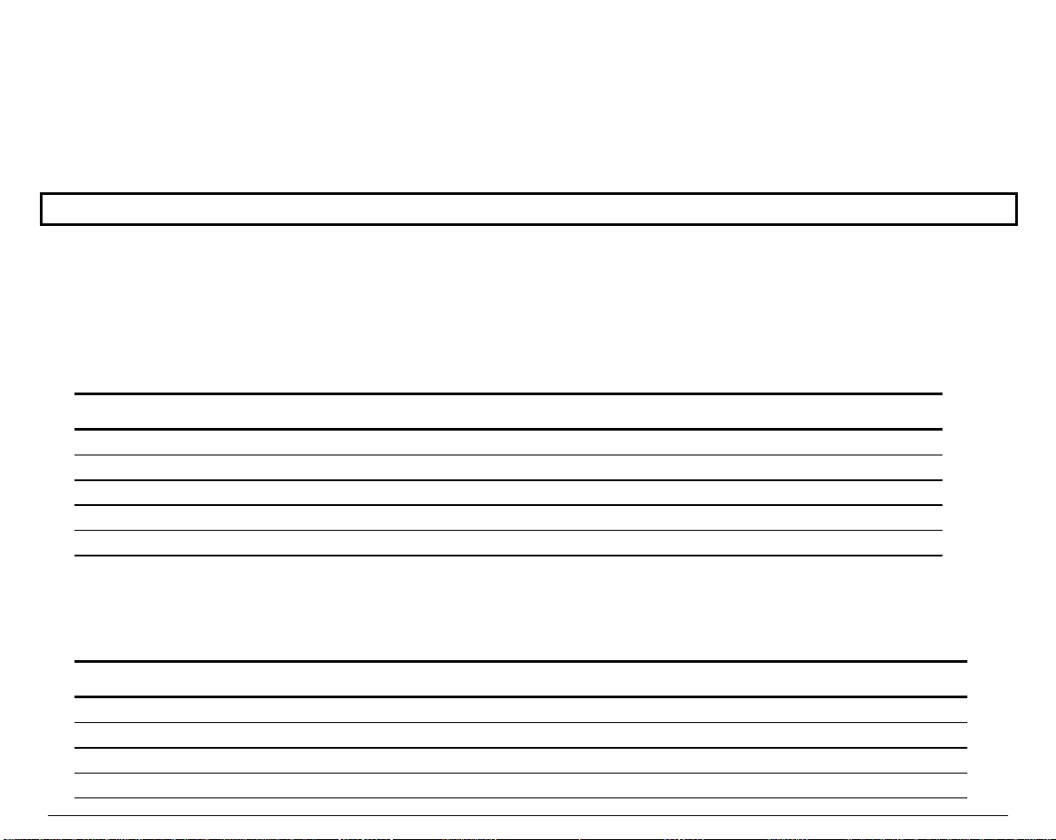
SSeettttiinngg tthhee PPrriinntteerr IInnssttaallllaattiioonn
The installation Values are generally set once when the printer is integrated within its
operating environment. The settings concern the printer hardware Configuration and the
communication parameters. Use the INSTALLATION Function to alter these parameters.
Factory settings are shown in bold.
LCD Language
The printer display messages are available in five languages: English, German, Spanish, French
and Italian. In the INSTALLATION Function select the LANGUAGE Option to set the desired
language.
Value Definition
English
Deutsch
Español
Français
Italiano
English language.
German language.
Spanish language.
French language.
Italian language.
Error Buzzer
The ERROR BUZZER Option defines the buzzer behavior in Fault state.
Value Definition
1 beep
3 beeps
Continuous beep
No beep
The buzzer beeps once.
The buzzer beeps three times.
The buzzer beeps continuously, until the printer exits the Fault state.
The buzzer does not sound.
90
Page 95

Ribbon Type
The RIBBON TYPE Option defines the ribbon used with the printer.
Value Definition
Black
Color
The black ribbon is used.
The color ribbon is used.
Paper Path at Power-On
The PATH AT POWER-ON Option allows you to decide which path you want to be selected, when
the printer is powered-on.
Value Definition
Last sel. Path
From Macro
The paper path at power-on is the one that was selected before the
printer was powered off.
The path at power-on is the one from the current Macro.
Tractor Jam Sensor
This item appears only if the optional tractor with jam sensor is installed.
The TRACT. JAM SENSOR Option allows you to enable/disable the Jam Sensor on the tractor.
Value Definition
Enabled
Disabled
The jam sensor on the tractor signals paper jams to the printer.
The jam sensor does not check for paper jams.
91
Page 96

SSeettttiinngg tthhee CCoommmmuunniiccaattiioonn IInntteerrffaaccee
The communication parameters of your printer are grouped under the INTERFACE Function.
These settings must match those of the host with which you want to communicate. It is
necessary to know the host settings before selecting val ues for the printer interface.
Factory settings are shown in bold.
Interface Type
Determines the type of interface to be used.
Value Definition
Parallel
Serial
Automatic
The parallel interface only is enabled
The serial interface only is enabled.
Both interfaces are enabled. The printer switches automatically to the
proper interface type, according to the activated port. If you select this
value, adjust the
I/F TIME-OUT
Option accordingly.
Interface Time-out
The I/F TIME-OUT Option allows you to define the duration after which the interface switches
back to the Stand-by state, when the printer stops receiving data.
Value Definition
2 seconds
...
30 seconds
Interface time-out of the corresponding duration.
92
Page 97

Input Buffer Size
The INPUT BUFFER Option allows you to set the input buffer size. The down line loading of
characters is always available.
Value Definition
1 K
8 K
16 K
32 K
64 K
1 KByte input buffer.
8 KByte input buffer.
16 KByte input buffer.
32 KByte input buffer.
64 KByte input buffer
Setting the Parallel Interface
Parallel Mode
The PARALLEL MODE Option allows you to determine the type of data exchange between the
printer and the host for the parallel interface.
Value Definition
Bidirectional
Centro
The parallel interface uses the IEEE 1284 bidirectional standard mode.
Select this Value to take advantage of the Plug and Play feature of Windows
95/98/2000®.
The parallel interface uses a Centronics monodirectional standard mode.
93
Page 98

AUTOFEED Signal
The AUTOFEED SIGNAL Option allows you to determine if the parallel interface ignores the
AUTOFEED signal or not.
Value Definition
Disabled
Enabled
The parallel interface ignores the AUTOFEED signal.
The parallel interface uses the AUTOFEED signal.
SELECT-IN Signal
The SLCT-IN SIGNAL Option allows you to determine if the parallel interface ignores the
SELECT-IN signal or not.
Value Definition
Disabled
Enabled
The parallel interface ignores the SELECT-IN signal.
The parallel interface uses the SELECT-IN signal.
94
Page 99

Setting the Serial Interface
Disconnection on Fault
The DISCON. ON FAULT Option defines the DTR line behavior for any fault condition detected
by the printer.
Value Definition
No discon.
Yes (DTR drop)
Yes (DTR pulse)
Word Length
The WORD LENGTH Option allows you to determine the data format.
Value Definition
8 bit
7 bit
The DTR line does not change.
The DTR line is dropped to low signal level.
The DTR line is pulsed to high signal level with a 5 sec pulse.
The data are coded using 8 bit.
The data are coded using 7 bit.
95
Page 100

Baud Rate
The BAUD RATE Option allows you to set the transmission speed used for the communication
between the printer and the host. Ensure that the Value matches your host settings.
Value Definition
600 bps
1200 bps
2400 bps
4800 bps
9600 bps
19200 bps
38400 bps
600 bits per seconds.
1200 bits per seconds.
2400 bits per seconds.
4800 bits per seconds.
9600 bits per seconds.
19200 bits per seconds.
38400 bits per seconds.
Parity Bit
The PARITY BIT Option allows you to set the parity check type.
Value Definition
Even
Odd
None
The even parity check is used.
The odd parity check is performed.
No parity check is performed.
96
 Loading...