

Page 1

D
n
a
n
u
u
all
a
99005588
99005588D
Uss
U
err
e
M
M
a
Page 2

Compuprint Products Information
Thanks
Your printer is a reliable working equipment that will be very useful in your daily job.
Our printers have been designed to be compact and respectful of the work environment. They offer
a wide range of features and multiple functions that confirm the high technological level reached
by the printers with Compuprint brand.
To maintain these printing performances unchanged in the long run, Sferal wwt has
developed specific Compuprint branded consumables for each printer type (for example: ribbon
cartridges for dot matrix printers, toner and OPC cartridges for laser printers, bubble ink jet
cartridges for inkjet printers) that assure an excellent operation with high printing quality level
reliability.
Sferal wwt recommends to use only its original Compuprint branded consumables with
original packaging (identified by its holographic label). In this way, a proper use of the printer at
quality level stated in the product characteristics can be assured. All typical usage problems
related to not certified consumables may be avoided, such as an overall quality print level
degradation and, often, the reduction of the product life due to the fact that the proper working
conditions for the print heads, OPC cartridge and other printer parts are not assured.
Moreover, Sferal does not only certify its consumables in terms of working conditions but also
carefully controls their compliance with the international standard rules concerning:
• no cancerous materials;
• no flammability of the plastic materials;
• other standards
Sferal advises the customers not to use products for which the compliance to this safety rules are
not warranted. Finally seek your dealer or contact a Sferal office and be sure that you are supplied
with the original Compuprint branded consumables.
for choosing the 9058/58D printer.
Page 3

SSaaffeet
y
y
A. Never remove any printer cover unless it is necessary for the installation of a printer accessory
and expressly described in this manual.
B. Please retain the printer covers in a safe place because they should be reinstalled if you
decide to remove any printer accessory.
The following areas of the printer should be covered for safety reasons:
Rear Tractor Area Cover
t
IInnffoorrmmaattiioonn
ASF Installation Area
Tractor Fixing Area Covers
The above openings must always be protected with their cover when the corresponding option is
not installed. Do not touch inside and do not insert any object into these openings or into the
gears.
iii
Covers
Page 4

FFCCCC NNootteess
This equipment has bee n tested a nd found to co mply with the l imits fo r a Class B di gital device , pursuant to Part 15 of the FCC
Rules. These limits are designed to provide reasonable protection against harmful interference when the equipment is operated
in a commercial environment. This equipment generates, uses and can radiate radio frequency energy and, if not installed and
used in acco rdance with the in structio n m anual , may ca use h armful inte rference to radi o com muni cation s. Howe ver, the re is no
guarantee that interference will not occur in a particular installation. If this equipment does cause harmful interference to radio
or television reception, which can be determined by turning the equipment off and on, the user is encouraged to try to correct the
interference by one or more of the following measures:
• Reorient or relocate the receivi ng antenna.
• Increase the separation between the equipment and the receiver to outlets on different circuits.
• Consult the dealer or an experienced radio/TV technician for help.
Changes or modifications not expressly approved by the party responsible for compliance could avoid the user's authority to
operate the equipment. The use of a non-shielded interface cable with the referenced device is prohibited. The length of the
parallel interface cable must be 3 meters (10 feet) or less. The length of the serial interface cable must be 15 meters (50 feet) or
.
less.
CCaannaaddiiaann DD..OO..CC.. RRaaddiioo IInntteerrffeerreennccee RReegguullaattiioonn
This digital apparatus does not exceed the Class B limits for radio noise emission from digital apparatus as set out in the radio
interference regulations of the Canadian Department of Communications.
Le présent appareil numérique n'émet pas de bruits radioélectriques dépassant les limites applicables aux appareils numériques
de classe A prescrites dans le règlement sur le brouillage radioélectrique édicté par le ministère des communications du Canada
EEEECC RReegguullaattiioonnss
This equipment conforms to the EEC Directive 89/392 (the sound pre ssure, measured according to ISO 7779, does
not exceed 70 dBA).
.
Page 5

TTaabbllee ooff CCoonntteennttss
Safety Information......................................................... iii
FCC Notes...................................................................... iv
Canadian D.O.C. Radio Interference Regulation.......................iv
EEC Regulations............................................................................iv
Table of Contents........................................................... v
Getting to Know Your Printer ....................................... 1
Printer Features..............................................................................1
Unpacking Your Printer.................................................................2
Printer Parts....................................................................................3
Front View ...................................................................................3
Rear View.....................................................................................5
Setting Up Your Printer ................................................. 6
Choosing a Suitable Location........................................................6
Printer Assembly............................................................................7
Removal of the Shipment Locks................................................7
Ribbon Cartridge Installation....................................................8
Upper Push Tractor Installation (9058D model only)..........13
Host Computer Connection .........................................................15
Software Driver Selection............................................................16
Power Connection.........................................................................17
Selecting the Display Language................................. 19
Configuring the Printer................................................ 20
Operator Panel Presentation.......................................................20
Display Messages......................................................................21
Indicators ...................................................................................25
Function Keys............................................................................26
Printer Setups...............................................................................31
Entering the Printer Setups....................................................31
Moving within the Printer Setups...........................................31
Leaving the Printer Setups......................................................32
Power-On Configuration..............................................................33
Entering the Power-On Configuration...................................33
Program Setup..............................................................................64
Entering the Program Setup....................................................64
How to Select the Paper Path......................................................87
How to Use the Tear-Off Function..............................................88
Selection of the Paper Size.......................................................88
Adjusting the Tear-Off Position..............................................89
Selection of the Tear-Off Mode................................................90
How to Lock/Unlock the Access to the Printer Setups.............91
How to Handle the Paper Parking..............................................92
Paper Handling............................................................. 97
Paper Paths...................................................................................97
Paper Specifications.....................................................................98
Fanfold Paper (9058 and 9058D models)...............................98
Envelopes (9058 model only)...................................................98
Cut Sheets (9058 model only)..................................................99
Cut Sheets ...................................................................................100
Cut Sheets Loading Modes....................................................100
Loading Cut Sheets.................................................................101
Fanfold Paper..............................................................................103
Loading Paper Using the Lower Tractor..............................103
Loading Paper Using the Upper Tractor..............................110
Loading Paper Using the Lower Push Tractor and the Rear
Pull Tractor (option)................................................................115
Printer Maintenance and Troubleshooting.............. 118
Cleaning the Printer...................................................................118
Replacing the Ribbon Cartridge................................................119
Printing the Self Test.................................................................120
Error Handling............................................................................121
Options ....................................................................... 125
The Rear Pull Tractor................................................................125
Installing the Rear Pull Tractor............................................125
Removing the Rear Pull Tractor...........................................127
Automatic Sheet Feeder (ASF) ................................. 128
Color Kit.......................................................................................129
Pedestals......................................................................................130
Printer Specifications ................................................ 131
v
Page 6

Page 7

GGeettttiin
g
g
n
ttoo KKnnooww YYoouurr PPrriinntteerr
PPrriinntteerr FFeeaattuurreess
• 24 Needle Print Head
• 136 columns
• Draft printing at 480 cps, LQ printing at 133 cps
• IBM Proprinter XL24E/XL24AGM, Personal Printer 2391+ and EPSON LQ 1050-2550
(ESC /P) emulations
• Multiple copies (1 orig inal and 7 copies)
• Automatic paper path selection
• Easy operability via operator panel menu and S/W commands
• Optional Automatic Sheet Feeder (120 sheets capability) which handles cut sheets,
multicopies and envelopes, accepts up to two additional paper bins and includes paper stacker
• Optional color kit
• Usage of all specific features by means of the Specific Software Driver which is applicable to
the most popular S/W Packages
• Plug & Play capability for Windows 95/98/2000®
• Bi-directional IEEE 1284 parallel interface and standard serial RS-232/C and RS-422/A
interface. Automatic switching between the available interfaces.
1
Page 8

UUnnppaacckkiinngg YYoouurr PPrriinntteerr
(
y)
Together with the Installation Guide and the CD-ROM with the User Manual, the following items
are included in the box:
Notify any damage to your supplier.
Power Cable
Upper Push Tractor
9058D model onl
2
Ribbon Cartridge
Page 9

PPrriinntteerr PPaarrttss
FFrroonntt VViieeww
9058 model
Power Switch
Operator Panel
Paper Knob
Cut Sheet Support
Push Tractor C ove r
Paper Guides
3
Page 10

9058D model
Operator Panel
Paper Knob
Push Tractors Cover
Power Switch
4
Page 11

RReeaarr VViieeww
Rear Tractor Area
Inte rface C on n ectors
Cover
Rear Paper Slot
Top C o v er
Paper Knob
ASF Area Cover
Power Cable Connector
5
Rear Tractor Installation
Area Covers
Page 12

SSeettttiin
g
g
n
UUpp YYoouurr PPrriinntteerr
CChhoooossiinngg aa SSuuiittaabbllee LLooccaattiioonn
Consider the following points when you
choose the location for your printer:
The distance between the printer and
•
the host computer must not exceed
the length of the interface cable;
The location must be sturdy,
•
horizontal and stable;
Your printer must not be exposed to
•
direct sunlight, extreme heat, cold,
dust or humidity (see "
Specifications
You need an AC power outlet
•
" later);
Printer
compatible with the plug of the
printer's power cord. The voltage of
the outlet must
match the voltage
shown on the printer's Rating Plate;
Additionally, you must make sure that
when you install the printer in the
selected location, there are sufficient
clearances on all sides for easy operation.
The required space is shown in the
figure:
1
3
9
.
4
80 cm
31.5 in.
0
0
c
m
i
n
m
c
0
2
n
i
9
.
7
1
0
3
0
9
c
.
4
m
i
m
c
0
2
n
i
9
.
7
n
6
Page 13

PPrriinntteerr AAsssseemmbbllyy
RReemmoovvaall ooff tthhee SShhiippmmeenntt LLoocckkss
Open all the printer covers and make sure that you remove all the shipment locks from the
printer.
7
Page 14

RRiibbbboonn CCaarrttrriiddggee IInnssttaallllaattiioonn
g
g
Two types of black ribbon cartridges are available for this printer, depending on whether the
color kit is installed or not.
Make sure that you are using only Compuprint original consumables.
1. Make sure that the printer is turned off.
2. Find the ribbon cartridge am ong the accessories.
Ribbon guide
Tension Knob
Cartrid
e Pin
Color Kit Guide
Ribbon guide
Tension Knob
Ca rtrid
e Pin
to be used, when the color kit option is not
installed
to be used, when the color kit option is
installed
8
Page 15

3. Open the top cover using the
small handles on either side of the
top cover.
4. Turn the printer on. The print
carriage prepares for ribbon
cartridge installation.
9
Page 16

5. Before installing the ribbon cartridge, turn
the ribbon winding knob in the arrow
Ribbon Tension
Knob
direction (located on the cartridge) to take up
slack in the ribbon.
To avoid damage to the ribbon, do not turn the winding knob in the wrong direction.
6. Align the cartridge pi ns with the locking grooves on the left and right cartridge supports.
The cartridge (black “Long Life” or color) to be used when the color kit is installed has only one
groove.
10
Page 17

7. Slide and insert the ribbon guide between the print head and the ribbon guide mask holding it
perpendicular to the print head.
Make sure that the ribbon is inserted correctly between the print head and the print head mask.
If the color kit option is installed on your
printer insert the white plastic holder
onto the color kit as shown in the
following figure.
2.
12
Ribbon Guide
Holder for Color Kit
Color Kit
11
Page 18

8. Turn the ribbon winding knob in the
arrow direction (located on the
Ribbon Tension
Knob
cartridge) to take up slack in the
ribbon.
9. Push the cartridge down gently until it clips into place at all four locking points.
10. Turn the ribbon winding knob again in the direction of the arrow to take up slack in the
ribbon.
11. To ensure that the ribbon guide runs freely along the ribbon, manually move the print
carriage horizontally .
If you need to replace the used ribbon cartridge, see " Replacing The Ri bbon Cartridge ", later in
this manual.
12
Page 19

UUppppeerr PPuusshh TTrraaccttoorr IInnssttaallllaattiioonn ((99005588DD mmooddeell oonnllyy))
An additional push tractor is provided with the 9058D printer. This second push tractor unit can
be installed in front position (on the lower push tractor).
1. Find the upper push tractor among
the accessories.
2. Install the upper push tractor
aligning both its hooks with the
Lower Tractor Pin
lower push tractor pins and
inserting them into the
Up pe r Tractor Hook
corresponding pins. Push the upper
tractor until it is fully engaged.
Insert the connector cable in the
electrical connector located in the
lower push tractor.
Connector Cable
Elec trica l C o nne ctor
13
Page 20

3. The upper push tractor must be
installed as shown in figur e.
4. If you need to remove the upper push
tractor, turn the printer off. Take the
connector cable off and press on the
push buttons (located in the upper
push tractor hooks) to disengage the
tractor.
Push Button
14
Page 21

HHoosstt CCoommppuutteerr CCoonnnneeccttiioonn
This printer can be connected to your host computer via two available interfaces. The interface
connectors are located on the rear of the printer.
• A bidirectional IEEE1284 parallel interface
• A RS-232/C or RS-422/A serial interface
Before connecting the interface cable, make sure that the printer and the host computer are
Insert the parallel interface cable into the parallel connector and fasten it by means of the clips.
Insert the serial interface cable into the serial connector, and fasten it by means of the two
screws (use the screwdriver).
turned OFF.
Parallel interface Serial interface
15
Page 22

SSooffttwwaarree DDrriivveerr SSeelleeccttiioonn
At this point it is necessary to configure your printer for your application package. The
installation procedures depend upon the host environment.
Follow the instructions in the readme file you find on the CD-ROM.
In a WINDOWS 95/98/2000® environment the printer supports the Plug & Play feature.
The printer drivers of all Compuprint printers can be found at the Internet Address
http://www.compuprint.net
16
Page 23

PPoowweerr CCoonnnneeccttiioonn
Make sure that the power outlet matches the power rating of the printer. See the name plate of the
In case the power rating does not correspond DO NOT CONNECT THE PRINTER TO THE MAINS.
1. Make sure the power outlet is near the printer location and easily accessible.
2. Make sure that the power switch is in 0
position (OFF).
printer, that you find under the rear ASF cover.
Consult your dealer for help.
Always use a grounded outlet.
17
Page 24

3. Insert the power cable plug into the printer connector and the other power cable end i nto a
convenient outlet (the figure shows the European version).
12
4. If you need to turn the printer on, press the
power switch in the I position (ON).
18
Page 25

SSeelleeccttiin
g
g
y
y
g
g
g
g
The display messages for this pri nter can be di splayed i n five different lang uages: Engli sh (Default),
French, German, Italian and Spanish. To select the language, that you prefer, pr oceed as follows:
n
tthhee DDiisspplla
a
LLaan
n
a
uua
ee
1. Press the
message will be displayed:
2. When you release the
then,
3. Press the ↓ key to enter the setup. The first setup item is displayed:
4. Press the ↓ key until the language first level function is d isplayed :
5. Press the → key to pass to the second level functions:
or
6. Press the ↓ key until the setup language is displayed :
PROGRAM
key and keep i t pressed while powering on the printer until the following
RELEASE KEY
PROGRAM
key, the following messages will be displayed :
9058
PRINT OUT? NO
PARALL INTERFACE
FUNCTIONS
PAPER OVERLY? NO
SEQUENCE NONE
MENU ENGLISH
or
9058D
for the 9058 model
for the 9058D model
7. Press the → key to scroll the setup la nguages. When the desired l anguage i s displayed, press the
PROGRAM
in the selected language.
key to select it. The printer exits the setup. From now on the displa y messages appear
19
Page 26

CCoonnffi
g
g
g
g
i
n
uurriin
tthhee PPrriinntteerr
QUIET
READY
LFLOAD/FF
↓
↑
PARK
SHIFT
PROGRAM
SHIFT
↑
MICRO FEE D
↑
MACRO FONT
PAT H
OOppeerraattoorr PPaanneell PPrreesseennttaattiioonn
The operator panel enables you to perform many of the printer functions including paper path
selections, font selection and the printer setup.
ON LINE
The operator panel consists of:
• A 16 character display (Liquid Crystal Displ ay)
• Three function mode indicators
• Seven function keys
PROGRAM
PITCH
20
Page 27

DDiissppllaayy MMeessssaaggeess
The printer display is used to indicate the printer status or to request an user intervention and
gives the following information:
• when paper is already loaded and the printer is
off line (
READY
indicator unlit):
• when paper is already loaded and the
printer is on line (
READY
indicator lit):
M1 - Lower Push E
Current Macro
where:
M1, M2, M3, M4
ASF1
ASF2
ASF3
LOWER PUSH
UPPER PUSH
PUSH PULL
LOW.PUSH&MF
PSH-PLL&MF
MANUAL FORM
E, I
M1 - Lower Push
Current Macro
Current Paper Path
Current Emulation
Indicate which of the four User Macros is currently used.
Indicates which Paper Path i s currently used. The printer displays onl y the
messages related to the installed dev ices.
LOW.PUSH&MF:
are selected (9058 model only).
PSH-PLL&MF:
selected (9058 model only).
MANUAL FORM:
This acronym indicates the Emulation currently used. E indicates the
EPSON emulation, whereas I indicates the IBM emulation.
The lower push paper path and manual single sheet path
The push-pull paper path and manual single sheet path are
The manual single sheet path is selected (9058 model only).
Current Paper Path
21
Page 28

• when there is no paper loaded and the
printer is off line (
READY
indicator unlit):
• when there is no paper loaded and the
printer is on line (
READY
indicator lit):
Load Lower Push
Current P aper Path
where:
M1, M2, M3, M4
LOAD ASF1
LOAD ASF2
LOAD ASF3
LOAD LOWER PUSH
LOAD UPPER PUSH
LOAD LOW.PUSH&MF
LOAD MANUAL FORM
LOAD PSH-PLL&MF
LOAD PUSH-PULL
ASF1
ASF2
ASF3
LOWER PUSH
UPPER PUSH
PUSH-PULL
LOW.PUSH&MF
PSH-PLL&MF
MANUAL FORM
M1 - Lower Push
Current Macro
Indicate which of the four User Macros is currently used.
Indicates that the currently selected paper path is out of paper.
The messages are displayed only for the available paper paths, according
to the installed devices.
Indicates which Paper Path is currently used. The printer display s only
the messages related to the installed devices.
LOW.PUSH&MF:
path are selected (9058 model only).
PSH-PLL&MF:
are selected (9058 model only).
MANUAL FORM:
only).
The lower push paper path and manual single sheet
The push-pull paper path and manual single sheet path
The manual single sheet path is selected (9058 model
Current Paper Path
22
Page 29

The following messages appear to indicate other printer conditions or user intervention requests.
The list is in alphabetical order:
Message Description
COVER OPEN
CLOSE COVER
When the printer cover is not closed correctly, the buzzer sounds and the
display shows alternately these two messages.
EJECTING
LOAD ASF1
LOAD ASF2
LOAD ASF3
LOAD LOWER PUSH
LOAD LOW.PUSH&MF
LOAD MANUAL FORM
LOAD PSH-PLL&MF
LOAD PUSH-PULL
LOAD UPPER PUSH
LOCKED MENU
MACRO CHANGING
MICRO FEED DOWN ↓
MICRO FEED UP ↑
OPER. INTERRUPTED
PARKING
The printer is ejecting the paper out of the printer.
These messages are displayed when the corresponding paper path is out of
paper.
The printer displays only the messages related to the installed
devices.
LOW.PUSH&MF
PSH-PLL&MF
= Lower push and manual paper path.
= Push-Pull and manual paper path.
When the access to the Printer Setups has been locked at the power on,
the printer displays this message.
The macro has been changed and the printer is updating the settings.
The paper is fed in microsteps downwards when pressing the arrow key.
The paper is fed in microsteps upwards when pressing the arrow key.
This message is displayed if th e
SHIFT
key has been pressed to interrupt a
park procedure.
The printer is parking the fanfold paper.
PATH CHANGING
PRESS A KEY
NVM CHANGED
The path has been changed and the printer is updating the settings.
The NVM has been changed. Press any key to set the pr inter.
23
Page 30

Message Description
QUIET PRINT OFF
Printing at normal noise level.
QUIET PRINT ON
RELEASE KEY
RESET & BREAK
SELF TEST
SHIFT FUNCTION
TEAR IF NECESS.
PARK PAPER
TEAR IF NECESS.
EJECT PAPER
TEAR OFF PAPER
PARK PAPER
TEAR OFF PAPER
EJECT PAPER
Printing at reduced noise level
This message is displayed when you can release the
PROGRAM
key in the
Self-test selection or in the Power-on Configuration procedure.
When the input buffer is cleared an a break (250 msec .) on a ser ial
interface is sent pressing the
PROGRAM
and then the
ON LINE
keys.
The printer is printing the self-test page.
This message appears to indicate that the Shift functions of the operator
panel keys have been selected pressing the
SHIFT
key.
These messages are displayed when the printer receives a paper parking
command. Tear off the fanfold then press the
key to park the paper.
PARK
These messages are displayed when the printer receives a paper parking
command and the TEAR NO is selected for the tear-off function. Tear off
the fanfold then press the
key to park the paper.
PARK
These messages are displayed when the printer receives a paper parking
command but was not able to execute it, because the paper to be parked is
longer than 18 inch. Tear off the fanfold paper and then press the
PARK
key to park the paper.
These messages are displayed when the printer receives a paper ejecting
command (TEAR NO has been selected for the tear-off function) but was
not able to execute it, because the paper to be ejected is longer than 18
inch. Tear off the fanfold paper and then press the
key to eject the
PARK
paper.
UNLOCKED MENU
For the error messages see "Error Handling" later in this manual.
When the access to the Printer Setups has been unlocked at the power on,
the printer displays this message.
24
Page 31

IInnddiiccaattoorrss
READY
PROGR AM
SHIFT
Lit when the printer can receive and print data (printer online).
Blinks when there is data in the buffer and the printer is offline.
Unlit, when the printer is disabled and the buffer does not contain any
data, or during the initialization, setup or tests.
Blinks when one of the printer setup procedures has been selected:
Program Configuration or Power-On Configuration.
Lit when the alternate function of the keys has been enabled pressing the
SHIFT
key.
25
Page 32

FFuunnccttiioonn KKeeyyss
The function keys are enabled, when the printer is offline (
have three functions each.
Normal Function
The normal function of the keys does not require previous action to select it.
This function is indicated in black characters beside the function keys.
Shift Function
The alternate function is selected pressing the
The alternate functions of the keys are described on the gray areas beside the
keys. The
This function is not enabled, if the printer is in setup mode.
SHIFT
indicator is lit and the display shows SHIFT FUNCTION.
Program Function
The program function is selected pressing the
• If you press the key while powering on the printer, the Power-On
Configuration is selected.
• Pressing the key when the printer is enabled without printing or disabled
(
READY
indicator unlit), the Program Setup is selected.
In the Program Setup mode only the four arrow keys and the
enabled.
READY
indicator unlit). The function key s
SHIFT
PROGRAM
key.
key, where:
PROGRAM
key are
When the printer is in setup mode, the
PROGRAM
indicator blinks.
26
Page 33

ON LINE Key
ON LINE
Normal
Function
Enables or disables the printer.
• If this key is pressed while powering the printer on, the self test is
printed; the printout is stopped pressing this key again.
• In an error condition, once the error cause has been removed, press
this key to enable the printer.
• If the Tear-Off Function in the Program Setup is set to Manual,
press this key to position the paper for the Tear-Off.
Program
Function
Pressing this key, the input buffer is cleared an a break (250 ms ec.) on
a serial interface is sent. The message RESET & BREAK is displayed.
PROGRAM Key
PROGRAM
Normal
Function
Enables the printer setups as follows:
• Pressing this key while powering on the printer, the Power-On
Configuration is selected.
• Pressing this key when the printer is enabled without printing or
disabled (
READY
indicator unlit), the Program Setup is enabled.
PITCH
Shift
Function
Program
Function
Selects the pitch to be used with the currently selected font. The
selected pitch is valid until th e printer is tur ned off .
Exits the current printer setup. See also “Leaving the Printer Setups”,
later in this section.
27
Page 34

SHIFT Key
SHIFT
Normal
Function
If no printing data are in the print buffer, pressing the
The display then shows SHIFT FUNCTION to indicate that the Shift
Shift Function Disables the alternative key functions.
LOAD/FF Key
LOAD/FF
Normal
Function
Enables the alternative key functions.
If the printer is receiving print data, press the
pressing the
SHIFT
key.
ON LINE
key before
SHIFT
key, the
printer goes offline.
Function of the keys is enabled.
May be used to abort paper parking procedure. See also “How to Handle
the Paper Parking”, later in this manual.
If pressed after the
key, the parking procedure is interrupted.
PARK
Executes a Form Feed (FF): when paper is loaded into the printer, it
advances to the following page; if no paper is loaded, it is positioned for
printing.
↑
Shift Function Moves the paper forward in microsteps. Keeping the key pressed the
paper is moved continuously at increasing speed.
↑
Program
Scrolls the parameters of the functions or macros backwards.
Function
28
Page 35

LF Key
LF
Normal
Function
↓
↓
Shift Function Moves the paper backward in microsteps. Keeping the key pressed the
Program
Function
MACRO Key
MACRO
Normal
Function
PATH
←
Shift Function Selects one of the paper paths. The parameters of the displayed path are
Program
Function
FONT Key
Performs a line feed according to the current line spacing settings.
paper is moved continuously at increasing speed.
Scrolls the setup and macro functions forward.
Selects one of the user macros (Macro 1, Macro 2, Macro 3 or Macro 4). If
you want to select the displayed macro, wait for 2 seconds without
pressing any key and the par ameters of this macr o will be set .
set pressing the
SHIFT
key or waiting for 2 seconds without pressing any
key.
Scrolls the setup and macro functions backward.
FONT
PARK
→
Normal
Function
Selects the font to be used with the currently selected pitch. The selected
font is valid until the printer is tur ned off .
Shift Function Parks the paper in the currently selected paper path.
Program
Scrolls the setup and macro functions forward.
Function
29
Page 36

Key Combinations
PROGRAM + SHIFT
ONLINE + MACRO + SHIFT
Normal
Function
Normal
Function
When the printer is on line without printing or
printing data (
READY
indicator lit) or when the
printer is unable to receive and print da ta but there
is still data in the input buffer (
READY
indicator
blinks) press these two keys contemporaneously, the
printing noise level toggles between normal (QUIET
PRINT OFF) and reduced noise level (QUIET PRINT
ON). When the printer is off line (
READY
indicator
unlit), the printing noise level function is disabled.
Lock or unlock the access to the printer setups. See
later “How to Lock/Unlock the Access to the Printer
Setups” section.
30
Page 37

PPrriinntteerr SSeettuuppss
The main printer setup parameters can be sel e cted via the operator panel. The setup parameters are
divided into two printer setups, the Power-O n Configuration, that allows a complete configuration at
installation time according to the hardware and the emulation types, and the Program Setup, that
allows you to set the functions that are the most useful in your daily job. This settings can be selected
when the printer is online without printing or offline (
stored in the NVM.
READY
indicator unlit). These setting s can be
EEnntteerriinngg tthhee PPrriinntteerr SSeettuuppss
• Press the
message is displayed to select the Power-On Configuration.
• Press the
unlit) to select the Program Setup .
PROGRAM
PROGRAM
key and keep it pressed at the printer power on until the RELEASE KEY
key when the printer is online without printing or offline (
MMoovviinngg wwiitthhiinn tthhee PPrriinntteerr SSeettuuppss
The arrow keys ↑, ↓, ← , → are used to move within the different functions inside the Printer Setups.
See the following description of the setup items.
READY
indicator
31
Page 38

LLeeaavviinngg tthhee PPrriinntteerr SSeettuuppss
• Pressing the
the new settings will be automatically saved.
PROGRAM
key in the Power-On Configuration the printer exits from the setup and
• Pressing the
values set:
STORE? QUIT
STORE? SAVE
STORE? CURRENT
Press the → or ← keys to scan these selections forwa rd and backwards. When the desired setting is
displayed, press the
PROGRAM
PROGRAM
key in the Program Setup, the following choice is offered to store the
The new settings are not activated and the old settings remain valid.
The new settings are stored permanently in the NVM (Non Volatile
Memory).
The new settings remain valid until the p rinter is tur ned off .
key to exit from the Setup.
32
Page 39

PPoowweerr--OOnn CCoonnffiigguurraattiioonn
The default values of the various functions are indicated in bold.
EEnntteerriinngg tthhee PPoowweerr--OOnn CCoonnffiigguurraattiioonn
1. Make sure that the printer is turned off.
2. Press and hold the
message is displayed. As soon as the
displayed:
then,
The following figure shows the structure of the Power-On Config uration and how to move inside the Setup.
PROGRAM
key pressed while powering on the printer until the RELEASE KEY
PROGRAM
9058 or 9058D
key gets released, the following message will be
PRINT OUT? NO
33
Page 40

Main Structure
g
g
Print out? NO
Parall Interface
Serial Interface
Functions
Back to MFG? NO
Print out? YES
Parallel Interface Settin
Serial Interface Settin
Functions Block
Back to MFG? YES
s
s
The functions concerning the interfaces group the parameters for the configuration of the
interfaces.
The setup item Functions groups the following printer functions:
• Paper overlay (9058 model only),
• Paper loading sequence,
• Buzzer setting,
• Quick cut sheet loading (9058 model only),
• Ribbon type,
• Code bar density,
• Text printing direction,
• Graphics printing direction,
• Bar code printing direction,
• Paper path at power on,
• Language of the display messages.
34
Page 41

Printout of the Printer Settings
PRINT OUT? NO
↓
PARALL INTERFACE
PRINT OUT? NO
PRINT OUT? YES
→
or ←
The Setup is not printed.
The printer setup is printed showing the currently selected values. The printout
PRINT OUT? YES
starts as soon as you select this value.
35
Page 42

Parallel Interface
This menu defines the use of the para llel interface and is structured according to the interface
specific parameters.
Parallel Interface Parameters
Para ll.Interface
Serial Interface
1284 Bidir. I/F
Select-In Host
Data Bits 8
Dedic . B u ffer 2 K
Emul EPSON
Char. Set ...
Nation ...
Auto CR ...
Auto L F ...
CX Pa ra lle l I/F
Select-In On
Data Bits 7
Dedic . B u ffer .. .
Em ul. IBM ...
Char. Set ...
Nation ...
Auto CR ...
Auto L F ...
20 C P I IBM ...
36
Page 43

Setting the Interface Parameters
Interface Type
PRINT OUT? NO PARALL INTERFACE
↓
↑
PARALL INTERFACE
CX PARALLEL I/F
↓
SERIAL INTERFACE SELECT-IN HOST
1284 BIDIR I/F
CX PARALLEL I/F
→
Bidirectional IEEE 1284 parallel interface.
Centronics type parallel interface (monodirectional)
1284 BIDIR I/F
↓
Setting the Select-In Signal
1284 BIDIR. I/F
↑
SELECT-IN HOST
SELECTIN ON
↓
DATA BITS 8
→
or ←
→ or ←
SELECT-IN ON
The SELECT-IN signal of the parallel interface is ignored and treated always as
ON.
SELECT-IN HOST
The printer checks the SELECT-IN signal coming from the host.
→
→
or ←
or ←
37
Page 44

Number of Data Bits
SELECT-IN HOST
↑
DATA BITS 8
DATA BITS 7
↓
DEDIC.BUFFER 2K
→ or ←
→ or ←
Selection of the number of data bits: 7 or 8
Input Buffer Size
DATA BITS 8
↑
DEDIC.BUFFER 256
DEDIC.BUFFER 2K
DEDIC.BUFFER 12K
DEDIC.BUFFER 32K
↓
EMUL. EPSON LQ
→ or ←
→ or ←
→ or ←
→ or ←
Selects the input buffer size. For the DLL the input buffer must be set to 2K.
38
Page 45

Printer Emulation
DEDIC.BUFFER 2K
↑
EMUL. EPSON LQ
EMUL. IBM XL24
EMUL. IBM XL24AGM
EMUL. IBM 2391
↓
CHAR. SET CS2
EMUL. EPSON LQ
EMUL. IBM XL24
EMUL. IBM XL24AGM
EMUL. IBM 2391
EPSON Character Sets
EMUL. EPSON LQ
↑
CHAR. SET CS1
CHAR. SET CS2
CHAR. SET ITALIC
↓
NATION CP437
→ or ←
→ or ←
→
or ←
→ or ←
The printer uses the EPSON LQ 1050/2550 emulation.
The printer uses the IBM Proprinter XL24e emulation.
The printer uses the IBM Proprinter XL24 AGM emulation.
The printer uses the IBM Personal 2391+ emulation.
→ or ←
→ or ←
→ or ←
These items select the character set to be used in EPSON emulation.
39
Page 46

IBM Character sets
EMUL. IBM xxx
↑
CHAR. SET CS1
CHAR. SET CS2
↓
NATION CP437
→ or ←
→ or ←
These items select the character set to be used in IBM Proprinter emulation.
EPSON National Character sets
CHAR. SET CS2
↑
NATION CP437
NATION ...
NATION LATIN A1
↓
AUTO CR YES
→ or ←
→ or ←
→ or ←
The following national character sets are available:
CP 437
CP 857 CP 858 CP 860 CP 862 CP 863 CP 864 CP 865 CP 866
CP 867 CP 876 CP 877 CP 1250 CP 1251 CP 1252 GOST TASS
MAZOWIA ISO 8859/1 ISO 8859/2 ISO 8859/3 ISO 8859/4 ISO 8859/5 ISO 8859/6 ISO 8859/7
CP437 G 96 GREEK CP850 CP851 CP 852 CP 853 CP 855
ISO 8859/8 ISO 8859/9 ISO 8859/15 USA FRANCE GERMANY ENGLAND DENMARK1
SWEDEN ITALY SPAIN1 JAPAN NORWAY DENMARK2 SPAIN2 LATIN A1
The CP 858 and ISO 8859/15 character sets contain the Euro character.
40
Page 47

IBM National Character Sets
CHAR. SET CS2
↑
NATION CP437
NATION ...
NATION 8859/15
↓
AUTO CR YES
→ or ←
→ or ←
→ or ←
The following national character sets can be selected:
CP 437
CP 857 CP 858 CP 860 CP 862 CP 863 CP 864 CP 865 CP 866
CP 867 CP 876 CP 877 CP 1250 CP 1251 CP 1252 GOST TASS
MAZOWIA ISO 8859/1 ISO 8859/2 ISO 8859/3 ISO 8859/4 ISO 8859/5 ISO 8859/6 ISO 8859/7
ISO 8859/8 ISO 8859/9 ISO 8859/15
CP437 G 96 GREEK CP850 CP851 CP 852 CP 853 CP 855
The CP 858 and ISO 8859/15 character sets contain the Euro character.
41
Page 48

CR Code Behavior
NATION xxx
↑
AUTO CR NO
AUTO CR YES
↓
AUTO LF NO
AUTO CR NO
No automatic carriage return is performed after a LF, VT or ESCJ code.
→ or ←
→ or ←
AUTO CR YES
The printer performs an automatic carriage return after a LF, VT or ESCJ code .
LF Code Behavior
AUTO CR YES
↑
AUTO LF NO
AUTO LF YES
AUTO LF HOST
↓
20 CPI IBM NO
or
PARALL INTERFACE
AUTO LF NO
AUTO LF YES
AUTO LF HOST
No Automatic LF after CR.
Automatic LF after CR.
Only in EPSON emulation. The printer checks the AUTOFEEDXT signal coming
from the host and executes an automatic LF after CR, if the signal is low.
→ or ←
→ or ←
→ or ←
42
Page 49

IBM Compressed Printing
These items are displayed only, if the IBM emulation is selected.
AUTO LF NO
↑
20 CPI IBM NO
20 CPI IBM YES
↓
PARALL INTERFACE
20 CPI IBM NO
20 CPI IBM YES
The compressed printing is performed at 17,1 cpi.
The compressed printing is performed at 20 cpi.
→ or ←
→ or ←
43
Page 50

Serial Interface
y
This menu defines the use of the serial interface and is structured according to the interface
specific parameters.
Serial Interface Parameters
Se ria l Inte rfac e
Se ria l I/F No
Baud 9600
Data Bits 8
Parity Non e
Handshake DTR
Connection Local
Dedic. B uffer 2K
Emul. EPSON
Char. Set ...
Nation ...
Auto CR ...
Au to L F …
Se ria l I/F ...
Baud ...
Data Bits 7
...
Parit
Handshake Xon/Xof
Connect. Remote
Dedic. B uffer ...
Emul. IBM ...
Char. Set...
Nation ...
Auto CR ...
Au to L F ...
20 CP I IBM ...
Functions
44
Page 51

Setting the Interface Parameters
Interface Type
PARALL INTERFACE
↑
SERIAL INTERFACE
↑
SERIAL INTERFACE
↓
FUNCTIONS
→
SERIAL I/F 232
SERIAL I/F 422
SERIAL I/F NO
↓
→ or ←
→ or ←
→ or ←
BAUD 9600
SERIAL I/F NO
The serial interface is disabled
SERIAL I/F 232 Defines the usage of the serial interf ace RS- 232/C
SERIAL I/F 422 Defines the usage of the serial interf ace RS- 422/A
45
Page 52

Baud Rate
SERIAL I/F NO
↑
BAUD 300
BAUD 600
BAUD 1200
BAUD 2400
BAUD 4800
BAUD 9600
BAUD 19200
BAUD 38400
↓
→ or ←
→ or ←
→ or ←
→ or ←
→ or ←
→ or ←
→ or ←
→ or ←
DATA BITS 8
The baud rate is selected in bits per second. The above values can be selected.
Number of Data Bits
BAUD 9600
↑
DATA BITS 8
DATA BITS 7
↓
PARITY NONE
→ or ←
→ or ←
Selection of the number of data bits: 7 or 8.
46
Page 53

Parity Check
DATA BITS 8
↑
PARITY NONE
PARITY ODD
PARITY EVEN
PARITY MARK
PARITY SPACE
↓
HANDSHAKE DTR
PARITY NONE
Data does not have a parity bit, i.e. 8 bit data are transferred and the parity check
is disabled.
PARITY ODD
PARITY EVEN
PARITY MARK
PARITY SPACE
Parity check is enabled for odd parity.
Parity check is enabled for even parity.
Parity check is disabled and the transmitted parity bit is always a Mark.
Parity check is disabled and the tr ansmitted p arity bit is always a Sp ace.
→ or ←
→ or ←
→ or ←
→ or ←
→ or ←
47
Page 54

Handshake Protocol
PARITY NONE
↑
HANDSHAKE DTR
HANDSHAKE XONXOF
↓
CONNECTION LOCAL
HANDSHAKE DTR
HANDSHAKE XONXOF
→ or ←
→ or ←
The Handshake is performed using the DTR Protocol.
The Handshake is performed using the XON-XOFF Protocol.
Connection Type
HANDSHAKE DTR
→ or ←
→ or ←
↑
CONNECTION LOCAL
CONNECT. REMOTE
↓
DEDIC.BUFFER 2K
Selects the connection type: local or remote.
48
Page 55

Input Buffer Size
CONNECTION LOCAL
↑
DEDIC.BUFFER 256
DEDIC.BUFFER 2K
DEDIC.BUFFER 12K
DEDIC.BUFFER 32K
↓
EMUL. EPSON LQ
→ or ←
→ or ←
→ or ←
→ or ←
Selects the input buffer size. For the DLL the input buffer must be set to 2K.
Printer Emulation
DEDIC.BUFFER 2K
↑
EMUL. EPSON LQ
EMUL. IBM XL24
EMUL. IBM XL24AGM
EMUL. IBM 2391
↓
CHAR. SET CS2
EMUL. EPSON LQ
EMUL. IBM XL24
→ or ←
→ or ←
→ or ←
→ or ←
The printer uses the EPSON LQ 1050/2550 emulation.
The printer uses the IBM Proprinter XL24e emulation.
EMUL. IBM XL24AGM
EMUL. IBM 2391
The printer uses the IBM Proprinter XL24 AGM emulation.
The printer uses the IBM Personal 2391 + emulation.
49
Page 56

EPSON Character Sets
EMUL. EPSON LQ
↑
CHAR. SET CS1
CHAR. SET CS2
CHAR. SET ITALIC
↓
NATION CP437
→ or ←
→ or ←
→ or ←
These items select the character set to be used in EPSON emulation.
IBM Character sets
EMUL. IBM xxx
↑
CHAR. SET CS1
CHAR. SET CS2
↓
NATION CP437
→ or ←
→ or ←
These items select the character set to be used in IBM Proprinter emulation.
50
Page 57

EPSON National Character sets
CHAR. SET CS2
↑
NATION CP437
NATION ...
NATION LATIN A1
↓
AUTO CR YES
→ or ←
→ or ←
→ or ←
The following national character sets are available:
CP 437
CP 857 CP 858 CP 860 CP 862 CP 863 CP 864 CP 865 CP 866
CP 867 CP 876 CP 877 CP 1250 CP 1251 CP 1252 GOST TASS
MAZOWIA ISO 8859/1 ISO 8859/2 ISO 8859/3 ISO 8859/4 ISO 8859/5 ISO 8859/6 ISO 8859/7
ISO 8859/8 ISO 8859/9 ISO 8859/15 USA FRANCE GERMANY ENGLAND DENMARK1
SWEDEN ITALY SPAIN1 JAPAN NORWAY DENMARK2 SPAIN2 LATIN A1
CP437 G 96 GREEK CP850 CP851 CP 852 CP 853 CP 855
The CP 858 and ISO 8859/15 character sets contain the Euro character.
51
Page 58

IBM National Character Sets
CHAR. SET CS2
↑
NATION CP437
NATION ...
NATION 8859/15
↓
AUTO CR: YES
→ or ←
→ or ←
→ or ←
The following national character sets can be selected:
CP 437
CP 857 CP 858 CP 860 CP 862 CP 863 CP 864 CP 865 CP 866
CP 867 CP 876 CP 877 CP 1250 CP 1251 CP 1252 GOST TASS
MAZOWIA ISO 8859/1 ISO 8859/2 ISO 8859/3 ISO 8859/4 ISO 8859/5 ISO 8859/6 ISO 8859/7
ISO 8859/8 ISO 8859/9 ISO 8859/15
CP437 G 96 GREEK CP850 CP851 CP 852 CP 853 CP 855
The CP 858 and ISO 8859/15 character sets contain the Euro character.
52
Page 59

CR Code Behavior
NATION xxx
↑
AUTO CR NO
AUTO CR YES
↓
AUTO LF NO
AUTO CR NO
AUTO CR YES
No automatic carriage return is performed after a LF, VT or ESCJ code.
The printer performs an automatic carriage return after a LF, VT or ESCJ code .
LF Code Behavior
AUTO CR YES
↑
AUTO LF NO
AUTO LF YES
↓
20 CPI IBM NO
or
SERIAL INTERFACE
AUTO LF NO
AUTO LF YES
No Automatic LF after CR.
Automatic LF after CR.
→ or ←
→ or ←
→ or ←
→ or ←
53
Page 60

IBM Compressed Printing
These items are displayed only, if the IBM emulation is selected.
AUTO LF:NO
↑
20 CPI IBM NO
20 CPI IBM YES
↓
SERIAL INTERFACE
20 CPI IBM NO
20 CPI IBM YES
The compressed printing is performed at 17,1 cpi.
The compressed printing is performed at 20 cpi.
→ or ←
→ or ←
54
Page 61

Functions
q
y
This item groups various printer functions, with which you can configure the printer.
9058 model
Functions
Back to Mfg? No
Paper Overly? No
Sequence None
Buzzer Yes
Quick Yes
Ribbon Black
Bar Codes 60
Tex t D i r e c t B i
Graph Direct Bi
Barcodes Dir. Uni
P.On Path Macro
Menu ENGLISH
Paper Overl
Se
uence ...
Buzzer No
Quick No
Ribbon Color
Bar Codes 90
Tex t D i r e c t U ni
Graph Direct Uni
Barcodes Dir. Bi
P.On Path Last
Menu …
? Yes
55
Page 62

9058D model
q
g
Functions
Back to Mf
? No
Sequence None
Buzzer Yes
Ribbon Black
Bar Codes 60
Text Direct Bi
Graph Direct Bi
Barcodes Dir. Uni
P.On Path Macro
Menu ENGLISH
uence ...
Se
Buzzer No
Ribbon Color
Bar Codes 90
Text Direct Uni
Graph Direct Uni
Barcodes Dir.Bi
P.On Path Last
Menu …
56
Page 63

Setting the Functions Group Items
SERIAL INTERFACE FUNCTIONS
↑
FUNCTIONS
SEQUENCE NONE 9058D
↓
BACK TO MFG: NO SEQUENCE NONE
→
↑
PAPER OVERLY NO 9058
↓
or
BUZZER YES
9058
9058D
Paper Overlapping (9058 model only)
FUNCTIONS
↑
PAPER OVERLY NO
PAPER OVERLY YES
↓
SEQUENCE NONE
PAPER OVERLY NO
→ or ←
→ or ←
When feeding a cut sheet through the manual entry slot, the fanfold paper
must be parked.
PAPER OVERLY YES
A single sheet can be fed simultaneously with a fanfold.
If the printer is using the Push Pull paper feed mode the Overlay Function cannot be selected.
Only the
Paper Overly No
item appears.
57
Page 64

Paper Loading Sequence
FUNCTIONS (9058D model)
or
PAPER OVERLY NO (9058 model)
↑
SEQUENCE NONE
SEQ. L + U PUSH (9058D model only)
SEQUENCE ASF1+2
SEQUENCE ASF123
↓
BUZZER YES
These items are displayed only, if the accessories to which they refer are installed.
SEQUENCE NONE
SEQ. L + U PUSH
The paper is fed only through the path selected by operator panel.
The paper is fed firstly through the lower push path and successively through
the upper push path (9058D model only) .
SEQUENCE ASF1+2
This item appears only, if the automatic sheet feed er is in stalled. Th e paper is
fed from the first bin until this bin is out of paper. Then the paper is fed from
the second bin.
SEQUENCE ASF123
This item appears only, if the automatic sheet feed er is in stalled. Th e paper is
fed from the first bin until this bin is out of paper. Then the paper is fed from
the second bin and finally from the third bin.
→ or ←
→
or ←
→ or ←
→ or ←
58
Page 65

Enable/Disable the Buzzer
SEQUENCE NONE
↑
BUZZER YES
BUZZER NO
↓
QUICK YES (9058 model)
or
BLACK RIBBON (9058D model)
→ or ←
→ or ←
Enable or disables the buzzer.
Quick Manual Loading through the Manual Slot (9058 model only)
BUZZER YES
↑
QUICK NO
QUICK YES
↓
RIBBON BLACK
QUICK NO
→ or ←
→ or ←
The single sheet in the manual path is loaded by the operator. The printer is then
disabled.
QUICK YES
The single sheet in the manual path is loaded au tomatically. The pr inter is th en
enabled.
59
Page 66

Ribbon Type Selection
QUICK YES (9058 model)
or
BUZZER YES (9058D model)
↑
RIBBON BLACK
RIBBON COLOR
↓
→ or ←
→ or ←
BAR CODE 60DPI
Selects the ribbon type to be used with the printer: black or color.
Bar Code Density
RIBBON BLACK
↑
BAR CODE 60DPI
BAR CODE 90DPI
↓
TEXT DIRECT BI
→ or ←
→ or ←
Selects the bar code print density: 60 or 9 0 dpi.
Text Print Direction
BAR CODE 60DPI
↑
TEXT DIRECT BI
→ or ←
TEXT DIRECT UNI
↓
→ or ←
GRAPH DIRECT BI
Selects the print direction for text: bidirectional or unidirectional.
60
Page 67

Graphics Print Direction
TEXT DIRECT BI
↑
GRAPH DIRECT BI
GRAPH DIRECT UNI
↓
→ or ←
→ or ←
BARCODES DIR.UNI
Selects the print direction for graphics: bidirectional or unidirectional.
Bar Codes Print Direction
GRAPH DIRECT BI
↑
BARCODES DIR.BI
BARCODES DIR.UNI
↓
P. ON PATH MACRO
→ or ←
→ or ←
Selects the print direction for bar codes: bidirectional or unidirectional.
61
Page 68

Paper Path at Power-On
BARCODES DIR.UNI
↑
P. ON PATH MACRO
P. ON PATH LAST
↓
MENU ENGLISH
→ or ←
→ or ←
P. ON PATH MACRO
P. ON PATH LAST
The paper path at power-on is the one from the default Macro.
The paper path at power-on is the last one that was selected before the printer
was powered off.
Selection of the Language of the Display Messages
P. ON PATH MACRO
↑
MENU ENGLISH
MENU ITALIANO
MENU FRANCAIS
MENU ESPANOL
MENUE DEUTSCH
↓
FUNCTIONS
→ or ←
→ or ←
→ or ←
→ or ←
→ or ←
These items are self explaining.
See also “Selecting the Display Language” before in this manual.
62
Page 69

Resetting to Factory Default Values
With the BACK TO MFG function it is possible to reset all items in the Power On Configuration
and in the Program Setup to their factory default values. This may be useful if you do not
remember the values you set in the menus, or because you simply changed you mind about the
settings you have just done. The default values for the menu items are indicated in bold
FUNCTIONS
↑
BACK TO MFG: NO
↓
or PROG
PRINT OUT ? NO
→ or
BACK TO MFG: YES
←
If you want to select BACK TO MFG:YES, you have to exit from this item using the ↑ or the ↓
key, in order to confirm the selection of this value.
At this point, the Power On Configuration Setup procedure is finished. If you exit pressi ng the ↓
and the
PROGRAM
key, the new settings will be saved.
Do not power off the printer before all data ha ve been written into the NVM and the printer has
returned online.
63
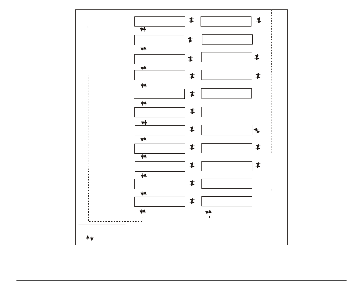
Page 70

PPrrooggrraamm SSeettuupp
The default values of the various functions are indicated in bold.
EEnntteerriinngg tthhee PPrrooggrraamm SSeettuupp
Press the
The following message will be displayed:
The following figure shows the structure and how to move inside the Program Setup.
PROGRAM
key when the printer is turned on and is offline or online without printing.
PRINT OUT? NO
64
Page 71

Main Structure
g
j
g
j
Print out? N o
User Macro
. M enu N o
Confi
Hex Dump No
us t: 0
Te a r a d
Print out? Yes
Macro# 1
Lin e s p. 6 lp i
...
MACRO PARAMETER BLOCK
Next Macro? No
Confi
. M enu Yes
Hex Dump Yes
us t: …
Te a r a d
The items define the following parameters:
…
Lin e s p. ...
Next M acro ? Ye s
Macro#4
• Four user macros
• The direct access to the Power-On Configuration
• Hexadecimal printout
• Tear-Off adjustment
65
Page 72

Printout of the Printer Settings
PRINT OUT? NO
↓
USER MACRO
→
or ←
PRINT OUT? YES
PRINT OUT? NO
PRINT OUT? YES
The Setup is not printed.
The printer setup is printed. The printout starts as soon as you select this
value.
NOTE
•
•
•
: The Program setup printout indicates:
the currently selected values,
the current selected macro is marked with the #x# symbols (
the current firmware release.
USER MACRO #x#),
66
Page 73

USER MACRO
The USER MACRO item allows to prepare four printing environments (MACRO#1, MACRO#2,
MACRO#3 and MACRO#4). Each macro is composed of a group of parameters which define a
configuration that can then be recalled to easily set the printer for four printi ng environments.
SELECTION OF THE USER MACRO
PRINT OUT? NO USER MACRO
↓
USER MACRO
↓
CONFIG MENU NO
MACRO # 4
→
MACRO # 2
MACRO # 3
↑
MACRO # 1
↓
LINE SP. 6 LPI
→
→
→
→
or
or
or
or
←
←
←
←
Selection of the macro for which you intend to set the parameters.
When a new macro is selected and the fanfold paper is present in the paper path set in the
previous macro, it will be automatically parked (
TEAR IF NECESS./PARK PAPER
is displayed).
Tear off this fanfold paper to avoid paper jams and press PARK key.
67
Page 74

USER MACRO PARAMETERS
g
g
g
g
User macro
Macro #1 Macro #2
Line sp. 6 lpi
Line sp. Lock No
th 1 Line
Len
Top of Form 0
Skipover 0
Font Draft
Pitch 10 cpi
Pitch Lock No
Left M ar
in 0
Macro #3 Macro #4
Line sp. ...
Line sp. Lock Yes
th ...
Len
Top of Form ...
Skipover …
Font …
Pitch …
Pitch Lock Yes
Left M ar
in …
68
Page 75
g
g
g
g
g
g
g
g
Right M argin 2 Right M argin …
Slash Zero No
Path L ow er P ush
Tear normal
Stron
im pact
Perfor. Safe No
Auto
ap 0
Tunin
: Horiz 0
Tunin
: Vert 0
Macro-> MFG No
Next macro? No
Slash Zero Yes
Path ...
Tear ….
Soft impact
Perfor. Safe Yes
Auto
ap ...
Tunin
: Horiz ...
Tunin
: Vert ...
Macro-> MFG Yes
Next macro? Yes
. Menu No
Confi
69
Page 76

Line Spacing
MACRO # 1
MACRO# 1
→
LINE SP. 8 LPI
LINE SP. 12 LPI
↑
LINE SP. 6 LPI
LINE SP 3L/30MM
LINE SP 4L/30MM
LINE SP 6L/30MM
LINE SP 8L/30MM
LINE SP 12L/30MM
↓
LINE SP LOCK NO
→ or ←
→ or ←
→ or ←
→ or ←
→ or ←
→ or ←
→ or ←
→ or ←
These values define the line spacing in lines/inch (6, 8, 12) or in lines per 30 mm (3, 4, 6, 8, 12).
Line Spacing Lock
LINE SP. 6 LPI
↑
LINE SP. LOCK NO
LINE SP. LOCK YES
↓
LENGTH xxx
LINE SP. LOCK NO
LINE SP. LOCK YES
→
←
or
→
←
or
Setting this item, the value set for vertical spacing can be changed by software
or operator panel.
Setting this item, the value set for vertical spacing cannot be changed by
software but only by operator panel.
70
Page 77

Page Length
LINE SP. LOCK NO
↑
LENGTH 1 LINE
LENGTH . .. LINES
LENGTH 244 LINES
LENGTH A5
LENGTH A4
LENGTH A3
LENGTH A2
LENGTH LEGAL
LENGTH LETTER
↓
TOP OF FORM 0
→ or ←
→ or ←
→ or ←
→ or ←
→ or ←
→ or ←
→ or ←
→ or ←
→ or ←
These items set the page length for fanfold pa per in number of lines depending on the current
vertical spacing. For the single sheets the page format can be specified in number of lines or the
standard formats LETTER, LEGAL, A2, A3, A4, A5. Default value is
66 lines
.
71
Page 78

Top of Form
LENGTH Xx
↑
TOP OF FORM 0
TOP OF FORM ...
TOP OF FORM xxx
↓
SKIPOVER 0
→ or ←
→ or ←
→ or ←
These items set the top of form. The values range between 0 and the page length - 1.
Skip Over Perforation
TOP OF FORM 0
↑
SKIPOVER 0
SKIPOVER ...
SKIPOVER xxx
↓
FONT Draft
→ or ←
→ or ←
→ or ←
These items set the skipover perforation. The values range between 0 and the page length - 1.
72
Page 79

Font Selection
SKIPOVER 0
↑
FONT Draft
FONT Courier
FONT OCR-B
FONT Gothic
FONT Prestige
FONT Presentor
FONT Script
FONT OCR-A
FONT Boldface
↓
PITCH 10 CPI
→ or ←
→ or ←
→ or ←
→ or ←
→ or ←
→ or ←
→ or ←
→ or ←
→ or ←
Selects the fonts. OCR-A and OCR-B only if the pitch is set to 5 or 10 cpi. Boldface can be
selected only if the proportional pitch ha s been selected (
PITCH PROP
).
73
Page 80

Pitch Selection
FONT Draft
↑
PITCH 5 CPI
PITCH 6 CPI
PITCH 7.5 CPI
PITCH 8.5 CPI
PITCH 10 CPI
PITCH 12 CPI
PITCH 15 CPI
PITCH 17.1 CPI
PITCH 20 CPI
PITCH 24 CPI
PITCH PROP
↓
PITCH
LOCK NO
→ or ←
→ or ←
→ or ←
→ or ←
→ or ←
→ or ←
→ or ←
→ or ←
→ or ←
→ or ←
→ or ←
These items set the horizontal spacing in cha racters per inch. The PROP item sets proportional
character spacing.
74
Page 81

Pitch Lock
PITCH 10 CPI
↑
PITCH LOCK NO
PITCH LOCK YES
↓
LEFT MARGIN 0
→ or ←
→ or ←
PITCH LOCK NO
PITCH LOCK YES
Left Margin
PITCH LOCK NO
↑
LEFT MARGIN 0
LEFT MARGIN ...
LEFT MARGIN xxx
↓
RIGHT MARGIN 136
Setting this item, the pitch can be changed by software or operator panel.
Setting this item, the pitch can be changed ONLY by operator panel.
→ or ←
→ or ←
→ or ←
The Left Margin is set in numbe r of columns (depending on the current pitch) starting from the
physical left edge.
75
Page 82

Right Margin
LEFT MARGIN 0
↑
RIGHT MARGIN. 2
RIGHT MARGIN. ...
RIGHT MARGIN. xxx
↓
SLASH ZERO NO
→ or ←
→ or ←
→ or ←
The Right Margin is set in number of col umns (depending on the current pitch) starting from the
physical left edge. The default value is
Zero Character Printing
RIGHT MARGIN 136
↑
SLASH ZERO NO
SLASH ZERO YES
↓
PATH LOWER PUSH
→ or ←
→ or ←
136
.
You can select the Zero character printing with or wi thout a slash.
76
Page 83

Paper Path Selection
This function defines the default paper path for the current macro.
SLASH ZERO NO
↑
PATH LOWER PUSH
PATH UPPER PUSH (9058D only)
PATH MANUAL FORM (9058 only)
PATH PUSH PULL
PATH ASF1
PATH ASF2
PATH ASF3
↓
TEAR NORMAL
→ or ←
→ or ←
→ or ←
→ or ←
→ or ←
→ or ←
→ or ←
PATH LOWER PUSH
Paper loading with the lower push tractor.
PATH UPPER PUSH
PATH MANUAL FORM
PATH PUSH PULL
PATH ASF1
PATH ASF2
PATH ASF3
Paper loading with the upper pus h tractor (9058D mode l only).
Paper loading using the manual single sheet path (9058 model only) .
Paper loading using the lower push tractor and the rear pull tractor.
Paper loading from the firs t bin of the AS F, if installed .
Paper loading from the seco nd bin of the ASF, if installed .
Paper loading from the third bin of the A SF, if inst alled.
77
Page 84

Tear-Off Mode
PATH LOWER PUSH
↑
TEAR NORMAL
TEAR AUTOMATIC
LABEL
TEAR NO
↓
STRONG IMPACT
TEAR NORMAL
TEAR AUTOMATIC
LABEL
TEAR NO
→ or ←
→ or ←
→ or ←
→ or ←
The Tear-Off Function is performed pressing the
ONLINE
key when the printer
is offline.
When the printer is not receiving any data, the paper is moved to the Tear-Off
position. It is returned to the Tear-Off position as soon as it receives printing
data.
This item must be set when printing on labels, in order to avoid paper jams.
The paper does not execute any backward movement. When pressing the
PARK
key, the paper is ejected.
The paper does not execute any backward movement.
See also “How to Use the Tear-Off Function” later in this chapter.
78
Page 85

Print Impact Strength
TEAR NORMAL
↑
STRONG IMPACT
SOFT IMPACT
↓
PERFOR. SAFE NO
STRONG IMPACT
SOFT IMPACT
→ or ←
→ or ←
The impact strength of the print head is set for printing on multicopy paper.
The impact strength of the print head is set for printing on single paper or few
copies. The printing noise is reduced.
Paper Perforation
This function allo ws to move the print head aside the paper when the fanfold paper perforati on
passes between the mylar and the print bar, to avoid paper jams. If the use of single sheets is
selected, this item is not displayed.
STRONG IMPACT
↑
PERFOR. SAFE NO
PERFOR. SAFE YES
↓
AUTOGAP 0
→ or ←
→ or ←
PERFOR. SAFE NO
PERFOR. SAFE YES
The function is disabled. The print head remains in its position, when the
perforation of the paper passes.
The function is enabled. The print head is moved aside, when the perforation
passes.
79
Page 86

Adjusting the Print Head Distance
PERFOR. SAFE NO
↑
AUTOGAP -5
AUTOGAP ...
AUTOGAP +3
MANUAL GAP
FIXED GAP 0.3
FIXED GAP ...
FIXED GAP 9.3
↓
TUNING.HORIZ 0
AUTOGAP xxx
MANUAL GAP
FIXED GAP xxx
→ or ←
→ or ←
→ or ←
→ or ←
→ or ←
→ or ←
→ or ←
Selecting one of these values sensing the paper thickness. Negative values reduce
the distance between the print head and the paper. Default value is
Selecting this item, the print head must be adjusted manually.
Selecting one of these values the printer adjusts the print head gap to a fixed
AUTOGAP 0
distance.
.
80
Page 87

Horizontal Character Tuning
AUTOGAP 0
↑
TUNING.HORIZ 0
TUNING.HORIZ ...
TUNING.HORIZ 60
↓
TUNING.VERT 0
→ or ←
→ or ←
→ or ←
These values adjust the distance between the left paper margin and the first print character.
The values correspond to 1/120 inch units, i.e. the tuning ranges between 0 and 0,5 inch.
Vertical Character Tuning
TUNING.HORIZ 0
↑
TUNING.VERT. -30
TUNING.VERT. ...
TUNING.VERT. 360
↓
MACRO -> MFG NO
→ or ←
→ or ←
→ or ←
These values adjust the distance betw een the top paper margin and the fi rst printable line. The
values correspond to 1/180 inch units, i.e. the tuning ranges between -1/6 and 2 inch. 0 is the
default value.
81
Page 88

Resetting the Macro Parameters to the Factory Defaults
TUNING.VERT. 0
↑
MACRO -> MFG NO
MACRO -> MFG YES
↓
NEXT MACRO? NO
MACRO -> MFG NO
MACRO -> MFG YES
→ or ←
→ or ←
The new values set for the macro p arameters will be the u sed.
The values set for the macro par ameters will be res et to their f actory
defaults.
82
Page 89

Selecting Another Macro
MACRO -> MFG NO
↑
NEXT MACRO? NO
↓
CONFIG MENU NO
→ or ←
NEXT MACRO? YES
↓
MACRO # 1
To pass over to another macro, select
MACRO#1
is displayed, then press the → key to pass over to
NEXT MACRO? YES
Pressing the ↓ or ↑ key the item
.
MACRO#2 (MACRO CHANGING
is
displayed.
When passing over from one macro to another, the fanfold paper loaded from the paper path,
selected in the previous macro, will be automatically parked (
TEAR IF NECESS./PARK PAPER
is
displayed). Tear off this fanfold paper and press the PARK key.
You can now set the parameters for Macro#2 as described above. In this way you prepare the
second printing environment .
Passing over from one macro to the other then sets two different printing environments.
83
Page 90

Passing over to the Power-On Configuration
At this point of the menu, it is possible to pass over to the Power On Configuration Functions
Setting.
NEXT MACRO NO
↑
CONFIG MENU NO
↓
→ or ←
CONFIG MENU YES
↓
HEX DUMP NO PARALL INTERFACE
These items are self-explaining.
Hexadecimal Dump
CONFIG MENU NO
↑
HEX DUMP NO
↓
TEAR ADJUST: xxxx
If you select HEX DUMP YES, press the
→ or ←
HEX DUMP YES
PROGRAM
key to set this item. The hexadecimal printing
continues, until the HEX DUMP NO item is selected, entering again into the Program Setup.
84
Page 91

Adjusting the Tear-Off Position
HEX DUMP NO
↑
TEAR ADJUST: - 30
TEAR ADJUST: ...
TEAR ADJUST: +360
↓
STORE? QUIT
TEAR ADJUST: xxxx
→ or ←
→ or ←
→ or ←
These values adjust the distance between the Tear-Off Perforation and the
Tear-Off Bar. The values corresp ond to 1/180 inch units, i.e. the tuning
ranges between -1/6 and 2 inch. 0 is the default value.
See also “How to Use the Tear-Off Function”, later in this Chapter.
85
Page 92

Storing the values
TEAR ADJUST: xxxx
↑
STORE? QUIT
STORE? SAVE
STORE? CURRENT
PROG
EXIT
→ or ←
→ or ←
→ or ←
STORE? QUIT
This setting does not save any of the new values set. The values set pr eviously
will be used.
STORE? SAVE
The values set are stored per manently (in the NVM) and will be us ed until
they are changed by the operator.
STORE? CURRENT
The values set are valid until the printer is turned off. When you turn the
printer on again, the values set in the pr eced ing menu setu p will be used .
At this point the Program Configuration Setup is finished. You exit pressing the
PROGRAM
key.
86
Page 93

HHooww ttoo SSeelleecctt tthhee PPaappeerr PPaatthh
The paper can be loaded into the printer usi ng different paper paths. The messages indicating
the paper paths are shown only if the corresponding loading device is installed on the printer.
Proceed as follows:
1. Press the
2. Press the
LOAD LOWER PUSH
LOAD UPPER PUSH
LOAD MANUAL
LOAD PUSH-PULL
READY
PATH
key to put the printer offline (the
key, according to the installed devices the following messages are displayed:
READY
indicator is unlit).
For the lower push tractor paper path.
For the upper push tractor paper path (9058D Model only).
For the manual cut sheet paper path (9058 Model only).
For the paper path using the lower push tractor and the optional rear pull
tractor.
LOAD ASF1
LOAD ASF2
LOAD ASF3
Loading a cut sheet from the first bin of the automatic sheet feeder.
Loading a cut sheet from the second bin of the automatic sheet feeder.
Loading a cut sheet from the third bin of the automatic sheet feeder.
• To load fanfold paper go to “Loading Paper Using the Lower Tractor” or “Loading Paper
Using the Upper Tractor”.
• To load manual cut sheets go to “Loading Cut Sheets”.
• For using paper with the Automatic Sheet Feeder option, consult the documentation you
receive together with the option.
When a new paper path is selected, the paper loaded in the printer is automatically
parked/ejected.
87
Page 94

HHooww ttoo UUssee tthhee TTeeaarr--OOffff FFuunnccttiioonn
This function is used to match the paper perforation with the tear-off bar. For this function the
following values must be set:
SSeelleeccttiioonn ooff tthhee PPaappeerr SSiizzee
1. Press the
Program Setup.
2. Press the ↓ key a nd the following message appears:
3. Press the → key to select the macro for which you want to set the paper size (
MACRO#2, MACRO#3
4. Once the desired macro is displayed press the ↓ key until the following parameter is
displayed:
5. Press the → or ← key until the desired page size is displayed.
6. Press again the
PROGRAM
key when the printer is disabled or enabled without printing to enter the
or
MACRO#4
PROGRAM
key to exit the menu end set the new value.
USER MACRO
MACRO#1,
).
LENGTH xx
88
Page 95

AAddjjuussttiinngg tthhee TTeeaarr--OOffff PPoossiittiioonn
The default value for the Tear-Off Function is TEAR NORMAL. To check the Tear-Off Position
proceed as follows:
1. To move the paper to the Tear-Off position, press the
disabled or enabled without printing.
2. Check if the paper perforation matches the tear-off bar on the printer.
If it does not:
1. Press the
2. Press the ↓ key until the following message appears:
3. Press the → key until the macro for which you want to adjust the tear-off is displayed
(#1,#2,#3 or #4):
4. Press the ↓ key until the following message is displayed:
5. Press the → or ← key to scroll the values of this function.
The values below 0 move the tear-off position downwards, values above 0 move the paper
upwards. The values can be set between -30 and 360 at 1/180 inches (-1/6 to 2 inches).
PROGRAM
key to enter the Program Setup.
USER MACRO
MACRO # x
TEAR ADJUST xxx
ON LINE
key when the printer is
6. When the desired value is displayed, press the
displayed.
7. Press the → or ← key, until the following message is displayed:
STORE? SAVE
8. Press the
PROGRAM
key to exit from the menu.
89
PROGRAM
key. The storage options are
Page 96

SSeelleeccttiioonn ooff tthhee TTeeaarr--OOffff MMooddee
It is now possible to select the Tear-Off Mode.
1. Press the
PROGRAM
key when the printer is disabled or enabled without printing to enter the
Program Setup.
2. Press the ↓ key. The following message is display ed:
USER MACRO
3. Press the → key to select the macro for which you want to set the tear-off mode
MACRO#2, MACRO#3
or
MACRO#4
).
4. Press the ↓ key, until the following message is displayed:
TEAR NORMAL
Pressing the → or ← key it is now possible to decide how to execute the tear off function:
TEAR NORMAL
Pressing the
ON LINE
Pressing again the
If the
ON LINE
key is not pressed for 10 seconds, the paper moves automatically
key the paper is moved to the tear-off position.
ON LINE
key, the paper is moved to the printing position.
back to the print position.
TEAR AUTOMATIC
If the printer is not receiving data, the paper is moved automatically to the tear
position.
LABEL
The
ON LINE
key is disabled for the tear-off function. This selection is useful
when printing on labels. Pressing the
key, the printer ejects the paper
PARK
towards the back of the printer.
MACRO#1,
TEAR NO
5. Press the
The Tear-Off function is disabled
PROGRAM
key to exit the setup.
90
Page 97

HHooww ttoo LLoocckk//UUnnlloocckk tthhee AAcccceessss ttoo tthhee PPrriinntteerr SSeettuuppss
To prevent not expertise persons changing the printer setup parameters, it is possible to
lock/unlock the access to the printer setups as follows:
Press
•
the printer on. As soon as these k eys are r eleased, the f ollowing messages will be displayed :
Now the access to the printer setups is locked. If the
message is displayed (the
If you decide to unlock the printer setup, turn the printer off, then press the
•
SHIFT
as these keys are released, the f ollowing mess ages will be disp layed:
ON LINE, MACRO
keys at the same time and keep them pressed while powering the printer on again. As soon
and
SHIFT
9058
PROGRAM
9058
keys at the same time and keep them pressed while powering
or
then,
LOCKED MENU
PROGRAM
key is disabled).
or
then,
9058D
key is pressed, the
ON LINE, MACRO
9058D
LOCKED MENU
and
UNLOCKED MENU
91
Page 98

HHooww ttoo HHaannddllee tthhee PPaappeerr PPaarrkkiinngg
According to the setting of the TEAR item in the Program Setup, the paper parking procedure is
performed in different ways. See the following description:
TEAR NO
If
is selected:
TEAR NO
• When the paper is positioned at the first
printable line and the paper path is changed
(changing the Macro or pressing the
key) or the
PARK
key is pressed, the printer
PATH
1st printable line
Other paper position
performs automatically the parking
procedure.
• If at least one line has been printed, or the
paper has been fed forward at least 1 line
and the paper path is changed (changi ng the
Macro or pressing the
PARK
key is pressed, the display shows
IF NECESS./PARK PAPER
PATH
key) or the
.
TEAR
MACRO or
PATH or
PAR K
MACRO or
PATH or
PAR K
If the paper to be parked is longer than 18"
tear it off and press the
perform the parking procedure.
PARK
key again to
PARKING
TEAR IF NECESS.
PARK PAPER
92
PAR K
PARKING
Page 99

If TEAR NORMAL is selected:
• When the paper is positioned at the
first printable line and the paper
path is changed (changing the
Macro or pressing the
PARK
the
key is pressed, the
PATH
key) or
printer performs automatically the
parking procedure.
• If at least one line has been
printed, or the paper has been fed
forward at least 1 line and the
paper path is changed (changing
the Macro or pressing the
key) or the
PARK
key is pressed,
PATH
the paper is moved to the tear-off
position and the display shows
TEAR IF NECESS./PARK PAPER.
If the paper to be parked is longer
than 18" tear it off and press the
PARK
key again to perform the
parking procedure.
• If the
ON LINE
key is pressed after
a print job and the paper has
moved in the tear-off position,
when pressing the
PARK
key the
printer performs automatically the
parking procedure.
1st printable line
MACRO or
PATH o r
PAR K
PARKING
TEAR NORMAL
Other paper position
Paper is moved to
tear-off position
TEAR IF NECESS.
MACRO or
PATH o r
PAR K
PARK PAPER
PAR K
PARKING
Print job
ON LINE
Paper is moved to
tear-off position
PAR K
PARKING
93
Page 100

If TEAR AUTOMATIC is selected:
• When the paper is positioned at the
first printable line and the paper path
is changed (changing the Macro or
pressing the
PATH
key) or the
PARK
key
is pressed, the printer performs
automatically the parking procedure.
• If at least one line has been printed, or
the paper has been fed forward at least
1 line and the paper path is changed
(changing the Macro or pressing the
PATH
key) or the
PARK
key is pressed,
the paper is moved to the tear-off
position and the display shows TEAR
IF NECESS./ PARK PAPER. If the
paper to be parked is longer than 18"
tear it off and press the
PARK
key again
to perform the parking procedure.
• If at least one line has been printed, or
the paper has been fed forward at least
1 line and the paper path is changed
(changing the Macro or pressing the
PATH
key) or the
PARK
key is pressed
when the paper is already in the tear
position, the printer performs
automatically the parking procedure.
TEAR AUTOMATIC
1st printable line
MACRO or
PATH o r
PAR K
PARKING
Other paper position
MACRO or
PATH o r
PAR K
TEAR IF NECESS.
PARK PAPER
PAR K
PARKING
Paper moved to
tear-off position
MACRO or
PATH o r
PAR K
PARKING
94
 Loading...