

Page 1

Network Video Recorder
RS-3232
Model No.
V2-120510
Page 2

Copyright
© 2012 Compro Technology, Inc. All rights reserved.
Trademark
Compro Technology is the registered trademarks of Compro
Technology Inc. Microsoft, Windows Vista, Windows and the Windows logo are
trademarks of the Microsoft group of companies. All other company and product
names mentioned in this document are registered trademarks of the respective
companies.
Restriction
No part of this document may be copied or reproduced in any form or by any
means without the prior written consent of Compro Technology, Inc.
Disclaimer
Compro Technology makes no warranties with respect to this documentation
and disclaims any implied warranties of merchantability, quality, or fitness for
any particular purpose. The information in this document is subject to change
without notice. COMPRO reserves the right to make revisions to this publication
without obligation to notify any person or entity of any such changes.
Revision History
2012/05/10 Original version
Compro Technology, Inc.
www.comprosecurity.com
Tel. +886 2 2918 0169, Fax +886 2 2915 2389
3F, No.12, Alley 6, Lane 45, Pao Shin Road,
Hsintien District, New Taipei City 231, Taiwan
Support e-mail: [email protected]
Page 3

Contents
Contents
I
Contents
Chapter 1: Important Notices . . . . . . . . . . . . . . . . . . . . . . . . . . . . . . . . . . . . . . . . . . . . . . . . . . . . . .1-1
Regulatory Notice . . . . . . . . . . . . . . . . . . . . . . . . . . . . . . . . . . . . . . . . . . . . . . . . . . . . . . . . . . 1-1
Operation Safety . . . . . . . . . . . . . . . . . . . . . . . . . . . . . . . . . . . . . . . . . . . . . . . . . . . . . . . . . . . 1-1
About this Manual . . . . . . . . . . . . . . . . . . . . . . . . . . . . . . . . . . . . . . . . . . . . . . . . . . . . . . . . . . 1-2
Conventions in this Manual . . . . . . . . . . . . . . . . . . . . . . . . . . . . . . . . . . . . . . . . . . . . . . . . . . . . 1-2
Chapter 2: Product Overview . . . . . . . . . . . . . . . . . . . . . . . . . . . . . . . . . . . . . . . . . . . . . . . . . . . . . .2-1
Introduction . . . . . . . . . . . . . . . . . . . . . . . . . . . . . . . . . . . . . . . . . . . . . . . . . . . . . . . . . . . . . . 2-1
Key Features . . . . . . . . . . . . . . . . . . . . . . . . . . . . . . . . . . . . . . . . . . . . . . . . . . . . . . . . . . . . . . 2-1
Supported Cameras . . . . . . . . . . . . . . . . . . . . . . . . . . . . . . . . . . . . . . . . . . . . . . . . . . . . . . . . . 2-1
Hardware Overview . . . . . . . . . . . . . . . . . . . . . . . . . . . . . . . . . . . . . . . . . . . . . . . . . . . . . . . . . 2-2
Rear Panel Connectors . . . . . . . . . . . . . . . . . . . . . . . . . . . . . . . . . . . . . . . . . . . . . . . . . . . . . 2-2
Typical Network Conguration . . . . . . . . . . . . . . . . . . . . . . . . . . . . . . . . . . . . . . . . . . . . . . . . . . 2-3
Chapter 3: Getting Started . . . . . . . . . . . . . . . . . . . . . . . . . . . . . . . . . . . . . . . . . . . . . . . . . . . . . . . .3-1
Package Contents . . . . . . . . . . . . . . . . . . . . . . . . . . . . . . . . . . . . . . . . . . . . . . . . . . . . . . . . . . 3 -1
Install Hard Disk Drive . . . . . . . . . . . . . . . . . . . . . . . . . . . . . . . . . . . . . . . . . . . . . . . . . . . . . . .3-1
Set Up RAID Level (Optional) . . . . . . . . . . . . . . . . . . . . . . . . . . . . . . . . . . . . . . . . . . . . . . . . . . . 3-2
Create a RAID Volume . . . . . . . . . . . . . . . . . . . . . . . . . . . . . . . . . . . . . . . . . . . . . . . . . . . . .3-2
Hardware Connections . . . . . . . . . . . . . . . . . . . . . . . . . . . . . . . . . . . . . . . . . . . . . . . . . . . . . . . 3-3
Power Connection . . . . . . . . . . . . . . . . . . . . . . . . . . . . . . . . . . . . . . . . . . . . . . . . . . . . . . . .3-3
Network Connection . . . . . . . . . . . . . . . . . . . . . . . . . . . . . . . . . . . . . . . . . . . . . . . . . . . . . . 3-3
Manually assign IP address (Optional) . . . . . . . . . . . . . . . . . . . . . . . . . . . . . . . . . . . . . . . . . . .3-4
Initial Setup . . . . . . . . . . . . . . . . . . . . . . . . . . . . . . . . . . . . . . . . . . . . . . . . . . . . . . . . . . . . . .3-6
Compro Wizard Setup . . . . . . . . . . . . . . . . . . . . . . . . . . . . . . . . . . . . . . . . . . . . . . . . . . . . .3-6
Camera Setup . . . . . . . . . . . . . . . . . . . . . . . . . . . . . . . . . . . . . . . . . . . . . . . . . . . . . . . . . .3-8
Remote Access . . . . . . . . . . . . . . . . . . . . . . . . . . . . . . . . . . . . . . . . . . . . . . . . . . . . . . . . . . . . 3-9
Access via ComproView® WebVUer . . . . . . . . . . . . . . . . . . . . . . . . . . . . . . . . . . . . . . . . . . . . . 3-9
Access over the Internet . . . . . . . . . . . . . . . . . . . . . . . . . . . . . . . . . . . . . . . . . . . . . . . . . . . . . 3 -10
Chapter 4: Main Workspace . . . . . . . . . . . . . . . . . . . . . . . . . . . . . . . . . . . . . . . . . . . . . . . . . . . . . . .4-1
Workspace Overview . . . . . . . . . . . . . . . . . . . . . . . . . . . . . . . . . . . . . . . . . . . . . . . . . . . . . . . . 4 -1
System Panel . . . . . . . . . . . . . . . . . . . . . . . . . . . . . . . . . . . . . . . . . . . . . . . . . . . . . . . . . . . . .4 -2
Utility Panel . . . . . . . . . . . . . . . . . . . . . . . . . . . . . . . . . . . . . . . . . . . . . . . . . . . . . . . . . . . . . . 4 -2
Viewport Panel . . . . . . . . . . . . . . . . . . . . . . . . . . . . . . . . . . . . . . . . . . . . . . . . . . . . . . . . . . . . 4-3
Event Index Panel . . . . . . . . . . . . . . . . . . . . . . . . . . . . . . . . . . . . . . . . . . . . . . . . . . . . . . . . . .4-4
ComproView® Log . . . . . . . . . . . . . . . . . . . . . . . . . . . . . . . . . . . . . . . . . . . . . . . . . . . . . . . .4-5
Log/Event Search Panel . . . . . . . . . . . . . . . . . . . . . . . . . . . . . . . . . . . . . . . . . . . . . . . . . . . .4-6
PTZ Function Panel . . . . . . . . . . . . . . . . . . . . . . . . . . . . . . . . . . . . . . . . . . . . . . . . . . . . . . . . .4-6
Right-Click Menu . . . . . . . . . . . . . . . . . . . . . . . . . . . . . . . . . . . . . . . . . . . . . . . . . . . . . . . . . . . 4 -7
System Status Panel . . . . . . . . . . . . . . . . . . . . . . . . . . . . . . . . . . . . . . . . . . . . . . . . . . . . . . . . .4-8
Panorama PTZ . . . . . . . . . . . . . . . . . . . . . . . . . . . . . . . . . . . . . . . . . . . . . . . . . . . . . . . . . . . .4-9
Detection Indicators . . . . . . . . . . . . . . . . . . . . . . . . . . . . . . . . . . . . . . . . . . . . . . . . . . . . . . .4 -10
Chapter 5: How to... . . . . . . . . . . . . . . . . . . . . . . . . . . . . . . . . . . . . . . . . . . . . . . . . . . . . . . . . . . . . . 5-1
Assign New IP Address to RS-3232 . . . . . . . . . . . . . . . . . . . . . . . . . . . . . . . . . . . . . . . . . . . . . . . . 5-1
Add Cameras . . . . . . . . . . . . . . . . . . . . . . . . . . . . . . . . . . . . . . . . . . . . . . . . . . . . . . . . . . . . . 5-3
Using Quick Setup Wizard . . . . . . . . . . . . . . . . . . . . . . . . . . . . . . . . . . . . . . . . . . . . . . . . . . . 5-3
Using System Conguration Console . . . . . . . . . . . . . . . . . . . . . . . . . . . . . . . . . . . . . . . . . . . .5-4
Using the Right-Click Menu . . . . . . . . . . . . . . . . . . . . . . . . . . . . . . . . . . . . . . . . . . . . . . . . . . 5-7
Using the Channel Control Panel . . . . . . . . . . . . . . . . . . . . . . . . . . . . . . . . . . . . . . . . . . . . . .5-8
Set Up Video Recording . . . . . . . . . . . . . . . . . . . . . . . . . . . . . . . . . . . . . . . . . . . . . . . . . . . . . .5-8
Schedule Video Recording. . . . . . . . . . . . . . . . . . . . . . . . . . . . . . . . . . . . . . . . . . . . . . . . . . . . . 5-8
Play Recordings . . . . . . . . . . . . . . . . . . . . . . . . . . . . . . . . . . . . . . . . . . . . . . . . . . . . . . . . . . . .5-9
Play Back from Backup . . . . . . . . . . . . . . . . . . . . . . . . . . . . . . . . . . . . . . . . . . . . . . . . . . . . 5 -11
Page 4

Contents
Compro RS-3232 - User's Manual
II
Customize Viewport . . . . . . . . . . . . . . . . . . . . . . . . . . . . . . . . . . . . . . . . . . . . . . . . . . . . . . . . 5-12
Drag-and-Drop . . . . . . . . . . . . . . . . . . . . . . . . . . . . . . . . . . . . . . . . . . . . . . . . . . . . . . . . . 5-12
Viewport Right-Click Menu . . . . . . . . . . . . . . . . . . . . . . . . . . . . . . . . . . . . . . . . . . . . . . . . . 5-12
Set Up Email Alert Messaging . . . . . . . . . . . . . . . . . . . . . . . . . . . . . . . . . . . . . . . . . . . . . . . . . . 5 -12
E-mail . . . . . . . . . . . . . . . . . . . . . . . . . . . . . . . . . . . . . . . . . . . . . . . . . . . . . . . . . . . . . . . 5-14
Set Up Multiple Monitors . . . . . . . . . . . . . . . . . . . . . . . . . . . . . . . . . . . . . . . . . . . . . . . . . . . . 5 -14
Set Up Event-based Recording . . . . . . . . . . . . . . . . . . . . . . . . . . . . . . . . . . . . . . . . . . . . . . . . . 5-15
Chapter 6: Live Monitoring . . . . . . . . . . . . . . . . . . . . . . . . . . . . . . . . . . . . . . . . . . . . . . . . . . . . . . . . 6-1
Channel Control Panel . . . . . . . . . . . . . . . . . . . . . . . . . . . . . . . . . . . . . . . . . . . . . . . . . . . . . . .6-1
Manage Video Pane Layout . . . . . . . . . . . . . . . . . . . . . . . . . . . . . . . . . . . . . . . . . . . . . . . . . . . . 6-1
Video Screen Layouts . . . . . . . . . . . . . . . . . . . . . . . . . . . . . . . . . . . . . . . . . . . . . . . . . . . . . . 6-1
Drag-and-Drop . . . . . . . . . . . . . . . . . . . . . . . . . . . . . . . . . . . . . . . . . . . . . . . . . . . . . . . . . . 6 -1
Viewport Right-Click Menu . . . . . . . . . . . . . . . . . . . . . . . . . . . . . . . . . . . . . . . . . . . . . . . . . . 6 -2
Group Cameras . . . . . . . . . . . . . . . . . . . . . . . . . . . . . . . . . . . . . . . . . . . . . . . . . . . . . . . . . . . . 6 -2
Group Setup Window . . . . . . . . . . . . . . . . . . . . . . . . . . . . . . . . . . . . . . . . . . . . . . . . . . . . . . 6 -2
Full Screen Mode . . . . . . . . . . . . . . . . . . . . . . . . . . . . . . . . . . . . . . . . . . . . . . . . . . . . . . . . . . . 6-3
Auto Scan Mode . . . . . . . . . . . . . . . . . . . . . . . . . . . . . . . . . . . . . . . . . . . . . . . . . . . . . . . . . . .6-3
Take a Snapshot . . . . . . . . . . . . . . . . . . . . . . . . . . . . . . . . . . . . . . . . . . . . . . . . . . . . . . . . . . .6-3
Manual Recording . . . . . . . . . . . . . . . . . . . . . . . . . . . . . . . . . . . . . . . . . . . . . . . . . . . . . . . . . . 6-3
PTZ Control . . . . . . . . . . . . . . . . . . . . . . . . . . . . . . . . . . . . . . . . . . . . . . . . . . . . . . . . . . . . . .6-4
Digital PTZ . . . . . . . . . . . . . . . . . . . . . . . . . . . . . . . . . . . . . . . . . . . . . . . . . . . . . . . . . . . .6-4
Preset Points . . . . . . . . . . . . . . . . . . . . . . . . . . . . . . . . . . . . . . . . . . . . . . . . . . . . . . . . . . .6-5
Center Mode (for PTZ Camera Only) . . . . . . . . . . . . . . . . . . . . . . . . . . . . . . . . . . . . . . . . . . . .6-5
Audio Control . . . . . . . . . . . . . . . . . . . . . . . . . . . . . . . . . . . . . . . . . . . . . . . . . . . . . . . . . . . . .6-6
Talk and Broadcast Voice . . . . . . . . . . . . . . . . . . . . . . . . . . . . . . . . . . . . . . . . . . . . . . . . . . . . . . 6-7
Chapter 7: Recording . . . . . . . . . . . . . . . . . . . . . . . . . . . . . . . . . . . . . . . . . . . . . . . . . . . . . . . . . . . . 7-1
Set Up Non-Stop Recording . . . . . . . . . . . . . . . . . . . . . . . . . . . . . . . . . . . . . . . . . . . . . . . . . . . . 7-1
Set Up Event-Triggered Recording . . . . . . . . . . . . . . . . . . . . . . . . . . . . . . . . . . . . . . . . . . . . . . . . 7-2
Set Up a Recording Schedule . . . . . . . . . . . . . . . . . . . . . . . . . . . . . . . . . . . . . . . . . . . . . . . . . . . 7-3
Schedule Non-Stop Recording . . . . . . . . . . . . . . . . . . . . . . . . . . . . . . . . . . . . . . . . . . . . . . . . 7-3
Schedule Event-Based Recording . . . . . . . . . . . . . . . . . . . . . . . . . . . . . . . . . . . . . . . . . . . . . . 7- 4
Enable/Disable Recording Schedules . . . . . . . . . . . . . . . . . . . . . . . . . . . . . . . . . . . . . . . . . . . . . . 7-5
Manual Recording . . . . . . . . . . . . . . . . . . . . . . . . . . . . . . . . . . . . . . . . . . . . . . . . . . . . . . . . . . 7-5
Chapter 8: Search & Playback . . . . . . . . . . . . . . . . . . . . . . . . . . . . . . . . . . . . . . . . . . . . . . . . . . . . . .8-1
Index Search Panel . . . . . . . . . . . . . . . . . . . . . . . . . . . . . . . . . . . . . . . . . . . . . . . . . . . . . . . . .8-1
Lock/Unlock Thumbnails . . . . . . . . . . . . . . . . . . . . . . . . . . . . . . . . . . . . . . . . . . . . . . . . . . .8-1
Allow/Disallow Snapshots and Recordings . . . . . . . . . . . . . . . . . . . . . . . . . . . . . . . . . . . . . . . . 8-1
Playback Console . . . . . . . . . . . . . . . . . . . . . . . . . . . . . . . . . . . . . . . . . . . . . . . . . . . . . . . . . .8 -2
Set Search Criteria . . . . . . . . . . . . . . . . . . . . . . . . . . . . . . . . . . . . . . . . . . . . . . . . . . . . . . . . 8-2
Camera Action . . . . . . . . . . . . . . . . . . . . . . . . . . . . . . . . . . . . . . . . . . . . . . . . . . . . . . . . . . 8-3
Using Smart Search . . . . . . . . . . . . . . . . . . . . . . . . . . . . . . . . . . . . . . . . . . . . . . . . . . . . . . . . .8-4
Play Back from Backup . . . . . . . . . . . . . . . . . . . . . . . . . . . . . . . . . . . . . . . . . . . . . . . . . . . . . . . 8-5
Playback Control . . . . . . . . . . . . . . . . . . . . . . . . . . . . . . . . . . . . . . . . . . . . . . . . . . . . . . . . . . .8-6
Synchronous Multi-Channel Playback . . . . . . . . . . . . . . . . . . . . . . . . . . . . . . . . . . . . . . . . . . . . .8-6
Playback Tools . . . . . . . . . . . . . . . . . . . . . . . . . . . . . . . . . . . . . . . . . . . . . . . . . . . . . . . . . . . .8-8
Add and Manage Bookmarks . . . . . . . . . . . . . . . . . . . . . . . . . . . . . . . . . . . . . . . . . . . . . . . . . . . 8-8
Add a Bookmark . . . . . . . . . . . . . . . . . . . . . . . . . . . . . . . . . . . . . . . . . . . . . . . . . . . . . . . . . 8-9
Rename and Remove Bookmarks . . . . . . . . . . . . . . . . . . . . . . . . . . . . . . . . . . . . . . . . . . . . . .8-9
Chapter 9: Backup . . . . . . . . . . . . . . . . . . . . . . . . . . . . . . . . . . . . . . . . . . . . . . . . . . . . . . . . . . . . . . 9 -1
Pre-Backup Setting . . . . . . . . . . . . . . . . . . . . . . . . . . . . . . . . . . . . . . . . . . . . . . . . . . . . . . . . .9-1
Add a Backup Directory . . . . . . . . . . . . . . . . . . . . . . . . . . . . . . . . . . . . . . . . . . . . . . . . . . . .9-1
Add a Backup Schedule Setting (For Scheduled Backup) . . . . . . . . . . . . . . . . . . . . . . . . . . . . . . .9-1
Page 5

Contents
Contents
III
Manual Backup . . . . . . . . . . . . . . . . . . . . . . . . . . . . . . . . . . . . . . . . . . . . . . . . . . . . . . . . . . . . 9-2
Schedule a Backup Operation . . . . . . . . . . . . . . . . . . . . . . . . . . . . . . . . . . . . . . . . . . . . . . . . . .9-3
Chapter 10: E-Map . . . . . . . . . . . . . . . . . . . . . . . . . . . . . . . . . . . . . . . . . . . . . . . . . . . . . . . . . . . . 10-1
E-Map . . . . . . . . . . . . . . . . . . . . . . . . . . . . . . . . . . . . . . . . . . . . . . . . . . . . . . . . . . . . . . . . . 10 -1
E-Map Editor . . . . . . . . . . . . . . . . . . . . . . . . . . . . . . . . . . . . . . . . . . . . . . . . . . . . . . . . . . . .10-1
Transformation Tools . . . . . . . . . . . . . . . . . . . . . . . . . . . . . . . . . . . . . . . . . . . . . . . . . . . . . 10-2
Add an E-Map . . . . . . . . . . . . . . . . . . . . . . . . . . . . . . . . . . . . . . . . . . . . . . . . . . . . . . . . . . . . 10 -3
Chapter 11: Remote Access . . . . . . . . . . . . . . . . . . . . . . . . . . . . . . . . . . . . . . . . . . . . . . . . . . . . . . . 11-1
ComproView® WebVUer . . . . . . . . . . . . . . . . . . . . . . . . . . . . . . . . . . . . . . . . . . . . . . . . . . . . . 11-1
Log Into RS-3232 on WebVUer . . . . . . . . . . . . . . . . . . . . . . . . . . . . . . . . . . . . . . . . . . . . . . . . . 11-2
Remote Monitoring on WebVUer . . . . . . . . . . . . . . . . . . . . . . . . . . . . . . . . . . . . . . . . . . . . . . . 11- 4
LiveView Page Layout . . . . . . . . . . . . . . . . . . . . . . . . . . . . . . . . . . . . . . . . . . . . . . . . . . . .11- 4
Icons on Live View Page . . . . . . . . . . . . . . . . . . . . . . . . . . . . . . . . . . . . . . . . . . . . . . . . . . . 11- 5
Right-Click Menu on LiveView Page . . . . . . . . . . . . . . . . . . . . . . . . . . . . . . . . . . . . . . . . . . . . 11- 6
Remote Playback on WebVUer . . . . . . . . . . . . . . . . . . . . . . . . . . . . . . . . . . . . . . . . . . . . . . . . . 11-7
Playback Page Layout. . . . . . . . . . . . . . . . . . . . . . . . . . . . . . . . . . . . . . . . . . . . . . . . . . . . . 11-7
Search for and Play Recordings . . . . . . . . . . . . . . . . . . . . . . . . . . . . . . . . . . . . . . . . . . . . . . . 11- 8
Play Back Recordings . . . . . . . . . . . . . . . . . . . . . . . . . . . . . . . . . . . . . . . . . . . . . . . . . . . . . 11- 9
Take a Snapshot . . . . . . . . . . . . . . . . . . . . . . . . . . . . . . . . . . . . . . . . . . . . . . . . . . . . . . . . 11- 9
Download a Recording . . . . . . . . . . . . . . . . . . . . . . . . . . . . . . . . . . . . . . . . . . . . . . . . . . . . 11-9
Chapter 12: Conguration . . . . . . . . . . . . . . . . . . . . . . . . . . . . . . . . . . . . . . . . . . . . . . . . . . . . . . . . 12-1
System Tab. . . . . . . . . . . . . . . . . . . . . . . . . . . . . . . . . . . . . . . . . . . . . . . . . . . . . . . . . . . . . . 12-1
System Settings . . . . . . . . . . . . . . . . . . . . . . . . . . . . . . . . . . . . . . . . . . . . . . . . . . . . . . . . 12-1
General Settings . . . . . . . . . . . . . . . . . . . . . . . . . . . . . . . . . . . . . . . . . . . . . . . . . . . . . . . . 12-1
User Interface Settings . . . . . . . . . . . . . . . . . . . . . . . . . . . . . . . . . . . . . . . . . . . . . . . . . . . . 12-2
Report Settings. . . . . . . . . . . . . . . . . . . . . . . . . . . . . . . . . . . . . . . . . . . . . . . . . . . . . . . . . 12-2
Log Settings . . . . . . . . . . . . . . . . . . . . . . . . . . . . . . . . . . . . . . . . . . . . . . . . . . . . . . . . . . . 12-3
Object Index Settings . . . . . . . . . . . . . . . . . . . . . . . . . . . . . . . . . . . . . . . . . . . . . . . . . . . . . 12-3
Ca mera Tab . . . . . . . . . . . . . . . . . . . . . . . . . . . . . . . . . . . . . . . . . . . . . . . . . . . . . . . . . . . . . 12- 4
Channel Settings . . . . . . . . . . . . . . . . . . . . . . . . . . . . . . . . . . . . . . . . . . . . . . . . . . . . . . . . 12- 4
General Settings . . . . . . . . . . . . . . . . . . . . . . . . . . . . . . . . . . . . . . . . . . . . . . . . . . . . . . . . 12- 4
Device Settings . . . . . . . . . . . . . . . . . . . . . . . . . . . . . . . . . . . . . . . . . . . . . . . . . . . . . . . . . 12-5
Recording Settings . . . . . . . . . . . . . . . . . . . . . . . . . . . . . . . . . . . . . . . . . . . . . . . . . . . . . . 12-7
Event Settings . . . . . . . . . . . . . . . . . . . . . . . . . . . . . . . . . . . . . . . . . . . . . . . . . . . . . . . . . 12-7
Notication Settings . . . . . . . . . . . . . . . . . . . . . . . . . . . . . . . . . . . . . . . . . . . . . . . . . . . . . 12-8
Detection Tab . . . . . . . . . . . . . . . . . . . . . . . . . . . . . . . . . . . . . . . . . . . . . . . . . . . . . . . . . . . . 12-9
Channel Settings . . . . . . . . . . . . . . . . . . . . . . . . . . . . . . . . . . . . . . . . . . . . . . . . . . . . . . . . 12-9
Audio Detection Settings . . . . . . . . . . . . . . . . . . . . . . . . . . . . . . . . . . . . . . . . . . . . . . . . . . 12-9
Motion Detection Settings . . . . . . . . . . . . . . . . . . . . . . . . . . . . . . . . . . . . . . . . . . . . . . . . . 12-9
Tampering Detection Settings . . . . . . . . . . . . . . . . . . . . . . . . . . . . . . . . . . . . . . . . . . . . . . 12-10
Intrusion Detection Settings . . . . . . . . . . . . . . . . . . . . . . . . . . . . . . . . . . . . . . . . . . . . . . . 12-10
Tripwire Detection Settings . . . . . . . . . . . . . . . . . . . . . . . . . . . . . . . . . . . . . . . . . . . . . . . . 12-10
Advanced Settings . . . . . . . . . . . . . . . . . . . . . . . . . . . . . . . . . . . . . . . . . . . . . . . . . . . . . 12-11
Schedule Tab . . . . . . . . . . . . . . . . . . . . . . . . . . . . . . . . . . . . . . . . . . . . . . . . . . . . . . . . . . . 12-12
Device & Operation Settings . . . . . . . . . . . . . . . . . . . . . . . . . . . . . . . . . . . . . . . . . . . . . . . 12-12
Mode Settings . . . . . . . . . . . . . . . . . . . . . . . . . . . . . . . . . . . . . . . . . . . . . . . . . . . . . . . . 12-12
Time Settings . . . . . . . . . . . . . . . . . . . . . . . . . . . . . . . . . . . . . . . . . . . . . . . . . . . . . . . . . 12-12
Operation Settings . . . . . . . . . . . . . . . . . . . . . . . . . . . . . . . . . . . . . . . . . . . . . . . . . . . . . 12-12
Schedule List . . . . . . . . . . . . . . . . . . . . . . . . . . . . . . . . . . . . . . . . . . . . . . . . . . . . . . . . . 12-13
Us er Tab . . . . . . . . . . . . . . . . . . . . . . . . . . . . . . . . . . . . . . . . . . . . . . . . . . . . . . . . . . . . . . 12-13
Group / User . . . . . . . . . . . . . . . . . . . . . . . . . . . . . . . . . . . . . . . . . . . . . . . . . . . . . . . . . 12-13
Group / User Settings . . . . . . . . . . . . . . . . . . . . . . . . . . . . . . . . . . . . . . . . . . . . . . . . . . . . 12-13
Option . . . . . . . . . . . . . . . . . . . . . . . . . . . . . . . . . . . . . . . . . . . . . . . . . . . . . . . . . . . . . 12-14
Page 6

Contents
Compro RS-3232 - User's Manual
IV
I/O Tab (Digital Input / Output devices). . . . . . . . . . . . . . . . . . . . . . . . . . . . . . . . . . . . . . . . . . . 12-14
Channel Settings . . . . . . . . . . . . . . . . . . . . . . . . . . . . . . . . . . . . . . . . . . . . . . . . . . . . . . . 12-14
General Settings . . . . . . . . . . . . . . . . . . . . . . . . . . . . . . . . . . . . . . . . . . . . . . . . . . . . . . . 12-14
Input Device Settings . . . . . . . . . . . . . . . . . . . . . . . . . . . . . . . . . . . . . . . . . . . . . . . . . . . . 12-14
Output Device Settings . . . . . . . . . . . . . . . . . . . . . . . . . . . . . . . . . . . . . . . . . . . . . . . . . . 12-15
Alert Tab . . . . . . . . . . . . . . . . . . . . . . . . . . . . . . . . . . . . . . . . . . . . . . . . . . . . . . . . . . . . . . 12-15
E-mail Settings . . . . . . . . . . . . . . . . . . . . . . . . . . . . . . . . . . . . . . . . . . . . . . . . . . . . . . . . 12-15
Sound Settings . . . . . . . . . . . . . . . . . . . . . . . . . . . . . . . . . . . . . . . . . . . . . . . . . . . . . . . . 12-16
Emap Settings . . . . . . . . . . . . . . . . . . . . . . . . . . . . . . . . . . . . . . . . . . . . . . . . . . . . . . . . 12-16
Message Settings . . . . . . . . . . . . . . . . . . . . . . . . . . . . . . . . . . . . . . . . . . . . . . . . . . . . . . 12-16
Storage Tab . . . . . . . . . . . . . . . . . . . . . . . . . . . . . . . . . . . . . . . . . . . . . . . . . . . . . . . . . . . . 12-17
Storage Object List . . . . . . . . . . . . . . . . . . . . . . . . . . . . . . . . . . . . . . . . . . . . . . . . . . . . . 12-17
Option Settings . . . . . . . . . . . . . . . . . . . . . . . . . . . . . . . . . . . . . . . . . . . . . . . . . . . . . . . 12-17
Channel Settings . . . . . . . . . . . . . . . . . . . . . . . . . . . . . . . . . . . . . . . . . . . . . . . . . . . . . . . 12-17
Settings . . . . . . . . . . . . . . . . . . . . . . . . . . . . . . . . . . . . . . . . . . . . . . . . . . . . . . . . . . . . 12-17
Capacity Settings . . . . . . . . . . . . . . . . . . . . . . . . . . . . . . . . . . . . . . . . . . . . . . . . . . . . . . 12-18
Network Tab . . . . . . . . . . . . . . . . . . . . . . . . . . . . . . . . . . . . . . . . . . . . . . . . . . . . . . . . . . . . 12-18
RTSP Setting . . . . . . . . . . . . . . . . . . . . . . . . . . . . . . . . . . . . . . . . . . . . . . . . . . . . . . . . . 12-18
Voice Out Settings . . . . . . . . . . . . . . . . . . . . . . . . . . . . . . . . . . . . . . . . . . . . . . . . . . . . . . 12-19
HTTP Server Setting . . . . . . . . . . . . . . . . . . . . . . . . . . . . . . . . . . . . . . . . . . . . . . . . . . . . . 12-19
Chapter 13: System Maintenance . . . . . . . . . . . . . . . . . . . . . . . . . . . . . . . . . . . . . . . . . . . . . . . . . . . 13-1
Using the Recovery CD . . . . . . . . . . . . . . . . . . . . . . . . . . . . . . . . . . . . . . . . . . . . . . . . . . . . . . 13-1
Chapter 14: Troubleshooting . . . . . . . . . . . . . . . . . . . . . . . . . . . . . . . . . . . . . . . . . . . . . . . . . . . . . . 14 -1
Enter Safe Mode . . . . . . . . . . . . . . . . . . . . . . . . . . . . . . . . . . . . . . . . . . . . . . . . . . . . . . . . . . 14-1
Trouble with IP Camera Discovery . . . . . . . . . . . . . . . . . . . . . . . . . . . . . . . . . . . . . . . . . . . . . . . 14-1
Trouble with Camera Connection . . . . . . . . . . . . . . . . . . . . . . . . . . . . . . . . . . . . . . . . . . . . . . . 14-2
Contacting Compro Technical Support . . . . . . . . . . . . . . . . . . . . . . . . . . . . . . . . . . . . . . . . . . . . 14 -3
Chapter 15: Technical Specications . . . . . . . . . . . . . . . . . . . . . . . . . . . . . . . . . . . . . . . . . . . . . . . . . 15-1
RS-3232 Technical Specications . . . . . . . . . . . . . . . . . . . . . . . . . . . . . . . . . . . . . . . . . . . . . . . . 15-1
Chapter 16: Appendix . . . . . . . . . . . . . . . . . . . . . . . . . . . . . . . . . . . . . . . . . . . . . . . . . . . . . . . . . .16-1
List of Figures and Tables . . . . . . . . . . . . . . . . . . . . . . . . . . . . . . . . . . . . . . . . . . . . . . . . . . . . 16-1
Index . . . . . . . . . . . . . . . . . . . . . . . . . . . . . . . . . . . . . . . . . . . . . . . . . . . . . . . . . . . . . . . . .16 -4
Page 7

Regulatory Notice
Chapter 1: Live View
1-1
Chapter 1: Important Notices
Regulatory Notice
This device complies with Part 15 of the FCC Rules. Operation is subject to the following two conditions: (1)
This device may not cause harmful interference, and (2) This device must accept any interference received,
including interference that may cause undesired operation.
FCC Interference Statement
This equipment has been tested and found to comply with the limits for a Class B digital device, pursuant
to Part 15 of the FCC Rules. These limits are designed to provide reasonable protection against harmful
interference in a residential installation.
This equipment generates, uses and can radiate radio frequency energy and, if not installed and used in
accordance with the instructions, may cause harmful interference to radio communications. However, there is
no guarantee that interference will not occur in a particular installation. If this equipment does cause harmful
interference to radio or television reception, which can be determined by turning the equipment o and on,
the user is encouraged to try to correct the interference by one of the following measures:
• Reorient or relocate the receiving antenna.
• Increase the separation between the equipment and receiver.
• Connect the equipment into an outlet on a circuit dierent from that to which the receiver is connected.
• Consult the dealer or an experienced radio/TV technician for help.
To assure continued compliance, any changes or modifications not expressly approved by the party
responsible for compliance could void the user's authority to operate this equipment.
Operation Safety
Before starting using the network video recorder, please read and follow the steps below to protect it.
• Please avoid walking on the power cord or placing heavy objects on it.
• Please do not block or cover the ventilation openings while the unit is in operation
• Place the product on an even surface at all times to avoid damage caused by falling o.
• Do not place this unit around products that produce heat, such as television or microwave oven; keep the
product away from direct sunshine.
• Unplug the power cord before cleaning the product.
• Do not shake, move or disturb the product when it is in operation, as such actions may result in the
malfunction of the device.
• Power o the unit as soon as it is found smoking or smelt unusual.
Page 8
About this Manual
Compro RS-3232 - User's Manual
1-2
About this Manual
This manual is only intended for the users of Compro RS-3232 network video recorder, which runs
ComproView® Premium 2.0. This manual will provide comprehensive understanding of the powerful
functions in ComproView and also elaborate in details of how to utilize these functions in the easiest way
possible. Compro RS-3232 supports ONVIF v1.0. For more information about ONVIF, visit www.onvif.org.
Should you encounter issues using ComproView and cannot nd a satisfactory solution in this manual, please
contact our support sta at [email protected].
Conventions in this Manual
While you are using this manual, pay attention to some symbols and notations that are used to draw
attention to special situations such as:
Caution!
Information provided here is critical to prevent damage to the product or
injury to the user.
!
Important:
Here it provides instructions that a user must follow in order to complete
a task.
Note:
Additional information or tips to help the user operate the product.
Page 9

Introduction
Chapter 2: Product Overview
2-1
Chapter 2: Product Overview
Introduction
RS-3232 is a 32-channel Windows-based network video recorder. This dual-bay RS-3232 is capable of
simultaneously recording 32 Megapixel IP video streams while providing multi-channel live view and
playback.
At the core of this powerful Surveillance System is the advanced video management system, ComproView®
Premium, which is pre-installed on the RS-3232 and is expressly designed to provide high-quality recording,
playback and management of IP video from multiple IP cameras. ComproView® is also capable of accessing
and managing Input/Output control devices connected to IP cameras which are either manufacturered by
Compro Technology or other surveillance product makers.
Furthermore, ComproView® Premium® is equipped with cutting-edge video analytics that can detect
intrusion, tampering attempts, and trip-wire events. ComproView® Premium can also generate thumbnails as
reference bookmarks for events detected on each video channel, which allows administrators to later retrieve
recordings in a precise time frame with a simple mouse click.
ComproView® Premium on the RS-3232 also offers a user-friendly remote web client that allows users to
conveniently monitor live image as well as search and play back video recordings over the Internet.
Key Features
• Support for dual SATA 3.0Gbs 3.5” HDD
• Windows XP Embedded for optimal performance and reliability
• Simultaneous 32-CH megapixel IP camera recording
• M-JPEG, MPEG-4, H.264 tri-codec, where applicable
• Support for ONVIF-compliant IP camera
• Pre-installed 32-CH ComproView® Premium
• Intelligent video analytics, detecting intrusion, tampering attempts and trip-wire events
• Web client for remote viewing, playback and video search
• Integrated e-Map to instantly locate events
• Full PTZ control
Supported Cameras
The supported IP cameras and IP devices are as follows:
• All network c - ameras and video servers in Compro IP Series and Compro NC Series.
• ONVIF-conformant IP cameras. (Compro Technology does not guarantee full functionality or compatibility
across ONVIF cameras; individual experience may vary based on the camera model and rmware used)
Page 10

Hardware Overview
Compro RS-3232 - User's Manual
2-2
Hardware Overview
Rear Panel Connectors
Figure 2-1. Rear Panel Connectors
PS/2 mouse connector – For connecting a PS/2 mouse.
PS/2 keyboard connector – For connecting a PS/2 keyboard.
COM port 1 – For connecting various peripherals.
COM port 2 – For connecting various peripherals.
VGA connector – For connecting to a monitor.
DVI port – For connecting to a monitor.
LAN port 1 – Use LAN port 1 to connect the unit to your LAN network.
LAN port 2 – Use LAN port 2 when LAN port 1 physically fails.
Microphone port – For connecting an external microphone.
USB ports – For connecting USB 2.0 devices.
Line in port – For connecting various audio sources.
Line out port – For connecting a speaker or a headphone.
Page 11

Typical Network Conguration
Chapter 2: Product Overview
2-3
Typical Network Conguration
The following gure exemplies a typical network conguration in which the RS-3232 and up to 32 network
cameras are located on the same LAN network behind a router, which connects the LAN network to the
Internet, and the user on the remote PC tries to accesses the RS-3232 over the Internet.
RS-3232
IP Camera x 32
Ethernet Switch
Home / Oce / ShopHome / Oce / Shop
Internet
Router or
Cable/DSL Modem
Remote
PC
Figure 2-2. Network Conguration
To allow the RS-3232 to be accessed remotely over the Internet, you have to set up the port forwarding (also
known as port mapping or virtual server on certain brands of routers) on your router. To do so, log in to your
router's web interface rst, and then, one after one, manually map the router's public ports to the private
ports and IP address the RS-3232 will be using on the LAN network. The default ports that are used by the RS3232 and must be forwarded on the router are as follows:
Service Port Number
HTTP 80 (user congurable)
RTSP 5155 (user congurable)
Command 5170 (user congurable)
Table 2-1. Ports involved in port forwarding setup
In this scenario, the RS-3232 installed on the same LAN network with your network cameras may have its IP
addresses and mapped ports on the router as follows (assuming the router is assigned with a xed public /
WAN IP address):
Device IP address Mapped Port on the Router
Router 61.220.20.16
(WAN / public IP)
RS-3232 192.168.1.101 (private) 2080
Table 2-2. Port mapping in scenario B
Log in to the router's configuration interface and set up the port forwarding / mapping / virtual server on
Page 12

Typical Network Conguration
Compro RS-3232 - User's Manual
2-4
the router as follows. As long as port forwarding is set up properly and cameras are connected to the RS3232, you will be able to watch live camera video from a remote location by logging into the RS-3232 on web
browser. In other words, there is no need to set up port forwarding for your IP cameras unless you would like
to access your IP camera directly from the Internet.
Service From (WAN IP) Forward to (LAN IP)
RS-3232 (HTTP port) 61.220.20.16:2080 192.168.1.101:80
RS-3232 (RTSP port) 61.220.20.16:5155 192.168.1.101:5155
RS-3232 (Command port) 61.220.20.16:5170 192.168.1.101:5170
Table 2-3. IP addresses in scenario B
Note:
Your router may require a reboot after port forwarding is set.
Now on a remote PC with Internet connection, you can open the Internet Explorer and enter the WAN (public)
IP address of your RS-3232/router, followed by a colon and the RS-3232's public HTTP port number, into the
browser's address bar to log in to the RS-3232. For example, enter "http://61.220.20.16:2080". (Note you can
also log in to the RS-3232's private IP address using another PC that connects to the same LAN network as the
RS-3232).
On the other hand, if your router uses a oating IP address, instead of a xed IP address, you need to enable
the Dynamic DNS (DDNS) feature on the router (that is, if the feature is available). And tie your router's up-todate WAN/public IP address to a hostname with which you can access your RS-3232 over the Internet. So you
can remotely access to your RS-3232 by log on to a static hostname, such as "http://rs3232.iddns.org:2080".
Consult the manufacturer of your router or refer to your router's user manual in case you need instructions on
DDNS conguration.
Page 13

Package Contents
Chapter 3: Getting Started
3-1
Chapter 3: Getting Started
Package Contents
Check the package contents to make sure you have the following items. If anything is missing, please don't
hesitate to contact your local distributor.
• Network video recorder x 1
• Power cord x 1
• RJ-45 LAN cable x 1
• Restore CD x 1
• Quick start guide x 1
Install Hard Disk Drive
Make sure the unit is powered o before you remove or install the hard disk trays.
1. Open the unit’s front lid, and then push the hard drive release button, marked 1 in the gure, to release
the lever from its locked position.
1
2
Figure 3-1. Remove HDD tray
2. Pull the lever slightly outward, and gently pull the hard drive tray out. Then align the mounting holes on
the hard drive to match that of the hard drive tray, and use screws to fasten the hard drive to the tray.
3. With the lever open, slide the hard drive tray into the drive bay. Then gently push the hard drive tray to
ensure a secure connection between the drive connector and the SATA connector inside the RS-3232.
Finally, push the lever to its locked position and close the front lid.
Caution!
DO NOT remove hard disk during operation. Doing so may cause damage
to your hard disk drives.
!
Important:
To install a second hard disk drive, repeat the previous steps.
Page 14
Set Up RAID Level (Optional)
Compro RS-3232 - User's Manual
3-2
Set Up RAID Level (Optional)
On the RS-3232, the RAID function is defaulted to On, and when you have installed two or more storage
devices, the RAID function will be automatically enabled. To enter the system’s RAID conguration interface,
press Ctrl-I when prompted during the Power-On Self Test (POST). Refer to the following section for detailed
steps.
Create a RAID Volume
1. Power up the system or restart it if it is already on.
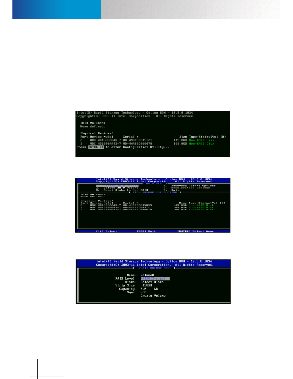
2. Press CTRL + I upon seeing the “<Press Ctrl-I…>” message in the rst few seconds after turning on the
system power to enter the RAID conguration interface.
Figure 3-2. Entering BIOS setup
3. Move the cursor to the “Create RAID Volume” option and press Enter.
Figure 3-3. Creating a RAID volume
4. Enter a volume name and press Enter. After that, select a RAID level by using the Up or Down arrow key
and then hit Enter.
Figure 3-4. Selecting a RAID level
5. Up comes a “Select Disks” window. Move the cursor up or down and press the Space bar to select two
physical disks. Then press Enter.
Page 15

Hardware Connections
Chapter 3: Getting Started
3-3
Figure 3-5. Choosing physical disks
6. After that, press Enter twice to use default strip size and capacity setting. Then press Enter again to
proceed with volume creation. Press the Y key when prompted with a warning message to conrm the
RAID volume creation.
Figure 3-6. Conrming the creation
7. Exit the RIAD conguration interface by choosing Exit.
8. Start up the system and follow the instructions of the Compro setup wizard to run a disk management
tool. Then go ahead to create a new disk volume using this tool and complete the setup.
!
Important:
• RS-3232 does not support a hard drive with greater than 2TB.
• If you intend to use RAID 1, it is recommended to install two identical
hard drives in the RS-3232.
• Compro does not guarantee full compatibility across all hard drives.
Please select a compatible hard drive model from www.comprousa.
com.
Hardware Connections
Power Connection
Connect the power cord to the power cord inlet on the unit’s rear panel. Then connect the other end of the
power cord to a power outlet.
Network Connection
Use a RJ-45 Ethernet cable to connect the LAN port 1 (located next to the VGA connector) of the unit to
an available Ethernet port on your network router/hub. In default mode, the RS-3232 is configured to
automatically obtain an IP address from your network router or from a DHCP server on your LAN network.
If the unit fails to obtain an IP address via DHCP, please manually assign an IP address to the unit.
Page 16

Hardware Connections
Compro RS-3232 - User's Manual
3-4
Figure 3-7. LAN 1 port
Manually assign IP address (Optional)
Alternatively, the unit can use a manually assigned IP address. Follow the steps below to assign an IP address.
1. Exit ComproView® on RS-3232.
2. Click the menu icon in the lower-left corner of the screen.
3. Choose “Control Panel” from the y-out menu, and then double-click “Network Connections.”
4. Double-click on the “Local Area Connection” icon. A connection status window will come up. Click on
“Properties” of that window.
Figure 3-8. Local Area Connection
5. A “Local Area Connection Properties” window pops up. Double-click “Internet Protocol (TCP/IP)” from a
list of items in this window.
6. An “Internet Protocol (TCP/IP) Properties” window is opened. Choose “Use the following IP address,” and
then punch in a new IP address, subnet mask, and default gateway. Please make note that if the unit and
your IP cameras are located on the same LAN network, ensure that they have the same subnet mask and
gateway.
Page 17

Hardware Connections
Chapter 3: Getting Started
3-5
Figure 3-9. Internet Protocol (TCP/IP) Properties
7. Click [OK] twice to save the IP address changes.
8. Click on the menu icon in the lower-left corner of the screen again, and choose “Save System Setting”
from the y-out menu.
Figure 3-10. Save system setting
9. An “Authentication” window is displayed. Please enter the default user name “administrator” (skip
password), and then click on “OK”.
Figure 3-11. Authentication window
10. Choose “Yes” when asked whether to restart the system to complete the conguration.
Page 18

Initial Setup
Compro RS-3232 - User's Manual
3-6
Initial Setup
Compro Wizard Setup
1. Connect the unit to a monitor and turn on the system power.
2. If this is the very rst time the RS-3232 starts up, it will run a Compro setup wizard. Click on “Next” to
continue.
Figure 3-12. Launch Compro Wizard
3. The wizard then automatically detects available storage devices on the system. Choose at least one disk
from the list for keeping ComproView® prole and recordings, and click “Next.” On the other hand, if the
wizard cannot nd any available disks, you will be prompted to run a “Disk Management Tool.”
Figure 3-13. Scan for available disks
4. When prompted, click on the text link to run the Disk Management Tool. Then go ahead and create a
new disk volume. Then go back to the wizard and select a disk to be used by ComproView®.
Page 19

Initial Setup
Chapter 3: Getting Started
3-7
Figure 3-14. Disk management tool
5. When complete, click [OK] to exit the setup wizard.
Figure 3-15. Wizard setup done
6. After the setup is done, the wizard launches ComproView® Premium. You will then be welcomed by a
login screen. Please enter the user name and password, which are both “admin” by default and hit Enter
to log in.
Page 20

Initial Setup
Compro RS-3232 - User's Manual
3-8
Figure 3-16. Login screen
Camera Setup
1. Connect your IP cameras to the network switch that also connects to your RS-3232, and then power on
your IP cameras.
RS-3232
IP Camera
IP Camera
Hub /Switch
Local Area NetworkLocal Area Network
IP Camera
Monitoring PC
Figure 3-17. Connection diagram
2. Launch ComproView® on the RS-3232 and enter the user name and password, which are both “admin” by
default, to log in.
3. After that, you will be prompted to run a quick setup. Click on “Go” and let ComproView® search for
available IP cameras on your LAN network. If some cameras do not appear on the list, click on “Re-Scan”
to search again.
Page 21

Remote Access
Chapter 3: Getting Started
3-9
Figure 3-18. Quick setup
4. Then select a camera from the list and put in its user name and password. Then go ahead and click “Next”
to complete the connection setup for this camera.
5. To add more cameras to the system, click on the wrench icon and select “Quick Setup” from the yout menu. Then simply repeat previous steps to add the rest of your IP cameras to the system.
!
Important:
Compro Technology does not guarantee full functionality or
compatibility across ONVIF cameras; individual experience may vary
based on the camera model and rmware used.
Remote Access
Access via ComproView® WebVUer
ComproView® WebVUer is a remote web client developed for you to access your RS-3232 remotely either
from another PC on the same LAN network where you RS-3232 sits or from another PC on the Internet. To
access the RS-3232 remotely:
1. Open the Internet Explorer on your Windows PC and enter the RS-3232’s IP address into the address
eld.
2. A dialog box that requests the user name and password appears. Meanwhile, depending on local
settings, the browser may prompt a security bar saying “The website wants to install the following addon…” Click on the information bar and choose to install and run the add-on.
Page 22

Access over the Internet
Compro RS-3232 - User's Manual
3-10
Figure 3-19. Log in to ComproView® WebVUer
3. After that, enter a valid user name and password. Then click on “Log in.” The default user name and
password are both “admin.”
4. Now you can start using ComproView® WebVUer on Internet Explorer to access your RS-3232.
Access over the Internet
Before you can access the RS-3232 over the Internet, you have to assign a public/WAN IP address to the RS-
3232. The RS-3232 can obtain a public IP address by using DHCP, static IP address, or PPPoE connection. Refer
to the “Manually assign IP address” section for instructions on changing the RS-3232’s IP address.
Also, you need to congure port forwarding (also known as port mapping or virtual server) on your router
that connects your RS-3232 and IP cameras to the Internet, and map the RS-3232’s LAN IP address and private
network ports it uses to your router’s public ports. The default port numbers used by the RS-3232 include
80 (HTTP), 5155 (RTSP), and 5170 (Command). Refer to "Typical Network Configuration" section for more
information.
After you complete the port forwarding setup, you can then access the RS-3232 by entering its WAN (public)
IP address, followed by a colon and the RS-3232’s public HTTP port number, into the address eld of Internet
Explorer (for example, “http://61.220.20.16:80”). For more information on remote access on web browser, refer
to the “Remote Access” chapter.
Page 23

Workspace Overview
Chapter 4: Main Workspace
4-1
Chapter 4: Main Workspace
Workspace Overview
After a successful login, you will come to the main workspace of ComproView®. It is the interface you will
be using most frequently. Many functions are accessible in the main workspace, including playback, system
setup, status indicators, split view buttons, event index, and also PTZ control. Before using the functions in
the main workspace, you will need to set up channel connections to your network cameras. For instructions
on adding camera connections, please refer to the “Add cameras” section of this manual. In split view, you can
re-arrange the channel order the way you like by clicking and dragging any video pane to a dierent location
of the video window
Figure 4-1. Main workspace
Video pane – Displays the live video feed of a particular channel. You can drag and drop a video pane to
a dierent position.
Channel information bar – Displays channel information.
Event index panel toggle button– Click on the toggle button to show/hide the channel control panel.
System status panel – Displays real-time information on CPU usage, disk usage and network utilization.
Channel control panel – For showing or hiding the channel control panel.
System panel – Provides access to main system functions.
Utility panel – Provides access to an assortment of system utilities.
Viewport panel – Allows you to change video pane layout and display mode.
Page 24

System Panel
Compro RS-3232 - User's Manual
4-2
Viewport toggle button – Click on the button to toggle the display of video screen layout buttons.
PTZ function panel – Lets you control the pan, tilt and zoom function of PTZ cameras and the digital PTZ
function.
System Panel
The followings are the main functional buttons seen in the system panel.
Icon Name Description
Main Click on the Main button to show the fly-out menu that contains the following
items.
• Start All: Enable all functions (analytics, scheduler, etc.) on all camera
channels.
• Start by Channel: Enable monitoring function (detection, scheduler, etc.)
only on selected camera channels. (A camera selection window will pop
up.)
• Stop Recording Schedule: Click here to start or stop your recording
schedule.
• Lock System: Lock the system to prevent unauthorized access. It requires
entering of user name and password to unlock.
• Minimize: Minimize ComproView® to system tray.
• Full Screen: Toggle to full screen mode.
• About ComproView®: Software version information.
• Logout: End the current user session.
• Quit: Quit ComproView®.
Start/Stop
All
Click to Start/Stop All detection and recording schedules on all camera channels
in ComproView®.
Index
Click to toggle displaying the Index Search Panel.
Playback
Click to bring up the playback console. See
Playback
chapter for details.
Table 4-1. System panel icons
Utility Panel
The followings are the main functional buttons seen in the utility panel.
Icon Name Description
Setup Click to open the setup menu, which lets you configure System, Camera,
Detection, Schedule, User, I/O, Alert, Storage and Network function in the system
conguration console.
Page 25

Viewport Panel
Chapter 4: Main Workspace
4-3
Icon Name Description
E-Map
Click to open the E-Map panel. See
E-Map
for details.
Backup
Click to bring up the backup console, which allows you to either manually backup
system data or schedule a backup operation.
Camera
Group
Click on the camera group button to show the y-out menu that contains the following items.
• Group Launch: Group the camera channels on a group list together so they
would be displayed together.
• Group Cancel: Ungroup the channels.
• Group Setup: Open the Group Setup panel.
I/O
I/O Control button lets you Enable/Disable the I/O control function of
ComproView®.
Speaker
Click to toggle on/o audio reception from cameras.
Index
Click and hold the talk button to broadcast your voice through the selected
camera’s built-in or external speaker.
Table 4-2. Utility panel icons
Viewport Panel
There are dierent video screen layouts available in the main workspace. If the video screen layout is 2 x 2
and 6 cameras are connected, only the rst 4 cameras can be viewed in the video screen. In this case, use
the following split view buttons to change to a layout greater than 2 x 2 in order to view all the connected
cameras.
Icon Name Description
Full Screen
Switch to full screen view. To exit, press ESC key.
Auto Scan
Click to rotate through all the camera channels.
Snapshot
Select a channel and click to take a snapshot. See "
Take a Snapshot
."
1 x 1 Layout Switch to a 1 x 1 video screen layout.
2 x 2 Layout Switch to a 2 x 2 video screen layout.
6-Channel
Layout
Switch to a 6-channel video screen layout with the 1st channel occupying a bigger
portion of the screen.
Page 26

Event Index Panel
Compro RS-3232 - User's Manual
4-4
Icon Name Description
8-Channel
Layout
Switch to a 6-channel video screen layout with the 1st channel occupying a bigger
portion of the screen.
3 x 3 Layout Switch to a 3 x 3 video screen layout.
10-Channel
Layout
Switch to a 10-channel video screen layout with the 1st and 2nd channel
occupying the top section of the screen.
10-Channel
Layout
Switch to a 10-channel video screen layout with the 1st and 2nd channel
occupying the middle section of the screen.
10-Channel
Layout
Switch to a 10-channel video screen layout with the 1st and 2nd channel
occupying the middle section of the screen.
13-Channel
Layout
Switch to a 13-channel video screen layout with the 1st channel occupying a
bigger portion of the screen.
4 x 4 Layout Switch to a 4 x 4 video screen layout.
17-Channel
Layout
Switch to a 17-channel video screen layout with the 1st channel occupying a
bigger portion of the screen.
21-Channel
Layout
Switch to a 21-channel video screen layout with the 1st channel occupying a
bigger portion of the screen.
25-Channel
Layout
Switch to a 25-channel video screen layout with the 1st channel occupying a
bigger portion of the screen.
29-Channel
Layout
Switch to a 29-channel video screen layout with the 1st channel occupying a
bigger portion of the screen.
5 x 5 Layout Switch to a 5 x 5 video screen layout.
32-Channel
Layout
Switch to a 32-channel video screen layout with the user-selected channel being
displayed in an additional video pane at the center of the screen.
Table 4-3. Viewport panel icons
Event Index Panel
Event Index/Log is a very important component of the surveillance system. It allows users to quickly retrieve
information on channel events, camera events, system user connections, or other types of system operations.
Log window in ComproView® can be opened and displayed at the top of the screen by hitting an event index
button in the event panel. In addition, when you hit the log search button, represented by a magnier icon,
and choose "Log search" or "Event search" from the y-out menu, a search panel will appear at the bottom of
Page 27

Event Index Panel
Chapter 4: Main Workspace
4-5
the video screen.
Event Index Panel
Figure 4-2. Event index panel
ComproView® Log
Log contains much useful information. Each log stores dierent types of information. All can be sorted by
record number (No.), date/time, channel, type (event type), duration (per event), and message (additional
information). Click on one of these categories to sort the log list items.
Logs in ComproView® are categorized into several types: Camera, Channel, User and System. To view a
particular type of log, click on its corresponding icon in the event index panel. Then a log window will
appear on the screen. (Click on the same icon to close the log window.)
• Camera log: records Events triggered by cameras.
• Channel log: records the status of channel connections.
• User log: records status of remote client connections.
• System log: records all system operations.
Figure 4-3. Log window
Example of an event listed in the Camera log:
Page 28
PTZ Function Panel
Compro RS-3232 - User's Manual
4-6
No. Date/Time Channel Type Duration
9 2008/05/07 15:38:16:50 1 Motion 1:7
The log item shows an incident happened at 15:38:16 (:50 out of: 100 is half a sec long) on 2008/05/07, on
channel 1, and was a Motion event that lasted 1 and 7/100 second.
Log/Event Search Panel
Log search panel and event search panel both oer three dierent types of data parameters to help you
pinpoint the exact time and channel of a previous event. You can set either one or multiple search criteria
(channel, lter, or date/time). Then click on "Go" to perform a log search. The Log search result will then
turn up on the right half of the log search panel.
Figure 4-4. Log Search Panel
PTZ Function Panel
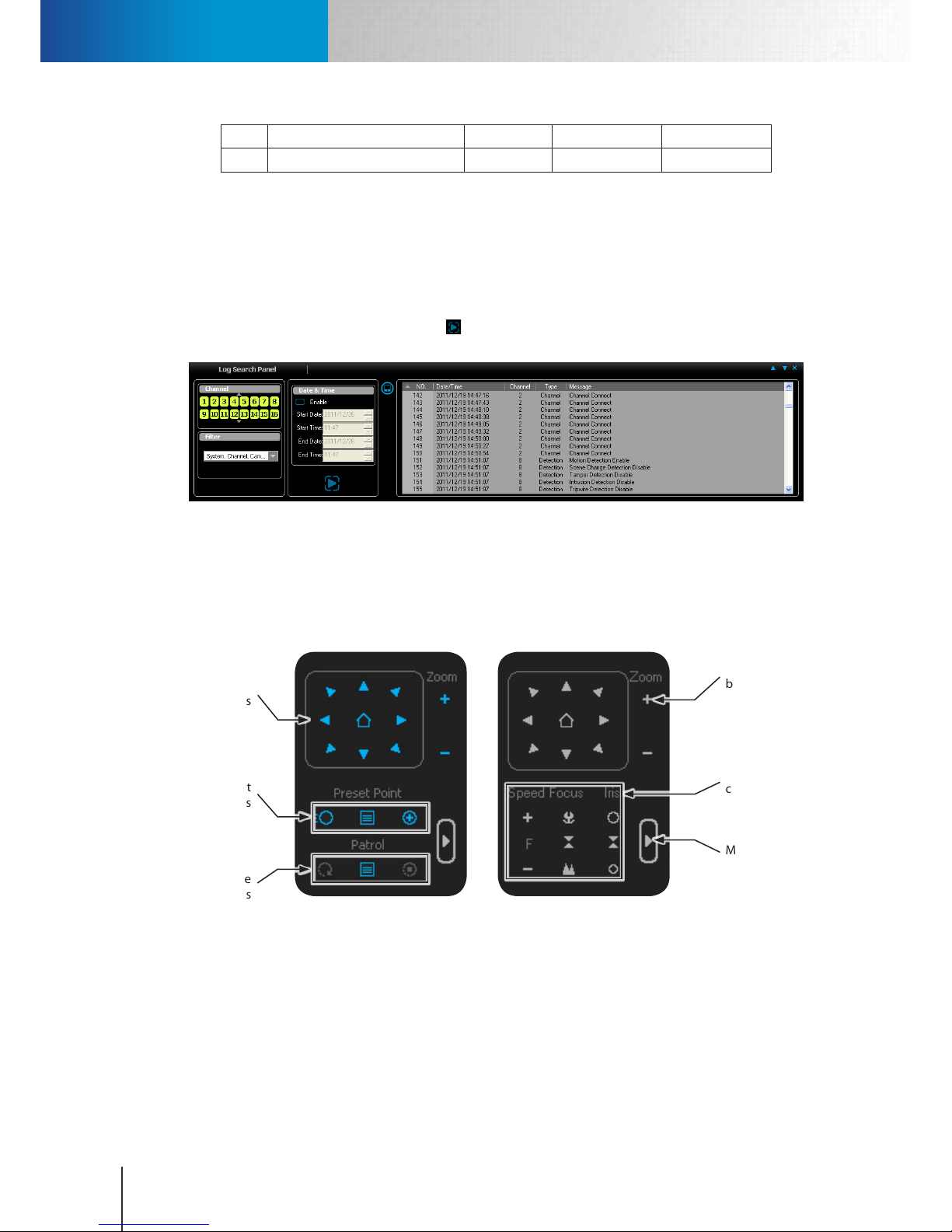
PTZ function buttons are located on the side of video window. When you select a channel connected to a PTZ
camera, such as a Compro IP540, the avaiable PTZ function buttons will turn blue. These buttons will allow
you to change camera position, zoom in/out, and perform other camera operations.
Directional
buttons
Zoom control
buttons
Mode button
Speed/Focus/Iris
control buttons
Preset point
buttons
Patrol mode
buttons
Figure 4-5. Directional buttons
• Directional buttons: 8 directional buttons plus a home position button.
• Preset point buttons: include a "Go to Preset Point" button (for moving PTZ camera to the selected preset
position), a "Preset Point Setting" button (for bringing up the quick preset point setting window) and an
"Edit Preset Point" button (for adding new preset points or editing existing preset points).
• Zoom control buttons: click the plus icon to zoom in; click the minus icon to zoom out.
• Patrol mode buttons: include a "Go" icon (for starting patrol), an "Edit" icon (for creating/deleting/editing
Page 29

Right-Click Menu
Chapter 4: Main Workspace
4-7
patrol groups), and a "Stop" icon (for stopping patrol).
• Mode button: lets you access advanced camera control buttons.
• Speed/Focus/Iris control buttons
1. Speed control: allows you to adjust the speed of PTZ movement. Click on the plus and minus icon to
toggle between F (Fast) and S (Slow).
2. Focus: Near ( ) / Auto focus ( ) / Far ( )
3. Iris: larger opening and brighter image ( ) / auto iris ( ) / smaller opening and dimmer image ( )
Right-Click Menu
The right-click menu provides quick access to some frequently used functions. This menu can be brought up
by a simple right click on any video pane in the main workspace. The channel you right-click on will be the
channel the right-click menu aects.
Figure 4-6. Right-click menu in ComproView®
Item Description
Connect
Establish connection with the IP camera.
Disconnect
Close connection with the IP camera of selected channel.
Camera Setup
Enter camera setup page.
Channel Setup
Enter channel setup page.
Detection Setup
Enter detection setup page.
Record
Manually start recording the selected channel.
Stop
Stop recording the selected channel manually.
Page 30

System Status Panel
Compro RS-3232 - User's Manual
4-8
Item Description
Manual Trigger
Manually trigger event responses on the selected channel; ComproView®
must be in monitoring mode (when "Start/Stop All" icon turns red) for the
manual trigger to work.
Viewport 1
Choose a different channel number (from 1 to 16) and assign the channel
number to the currently selected video pane.
Viewport 2
Choose a dierent channel number (from 17 to 32) and assign the channel
number to the currently selected video pane.
Center Mode
(For PTZ camera only.) When enabled, this option allows you to change the
center of view of the selected video pane by placing your cursor on any spot
on the live image and making a mouse click. ComproView® will then pan/tilt
the camera to make the point you click on the new center of view.
Digital PTZ
After you have selected Digital PTZ from the right-click menu, the Zoom
control buttons under PTZ Function will become accessible. Click “+” or “-” or
place your cursor on the selected video pane and scroll up/down to zoom in
and out. To pan/tilt, use the direction buttons or simply click and drag on the
channel pane being selected. This function works for network cameras with
xed lens or varifocal lens.
Panorama PTZ
Bring up the "Panorama PTZ" panel. Refer to the "Panorama PTZ" section for
details.
Auto Tracking
Choose to turn on/off the auto-tracking function of your PTZ camera that
supports on-board auto-tracking, such as that of a Compro NC500 camera.
Video
Enhancement
Setup
Bring up a Video Enhancement panel that allows you to adjust brightness,
contrast, hue, saturation, visibility, and sharpness. To apply enhancement,
check the "Enable" option, and then use the slider to adjust video quality to
your preference. After that click [OK] to save changes.
Disable Video
Enhancement
Turn o all video enhancement eects on the selected channel.
Table 4-4. Right-click menu
System Status Panel
The CPU/Disk/NET meter in the system status panel shows the current CPU loading, disk usage, and network
loading.
If you nd the CPU loading too high, please try shutting down unnecessary background applications. When
the system runs out of storage space, the disk meter will turn red. When this happens, free up some disk
space on your computer. If the network loading is too high; please try shutting down other applications that
Page 31
Panorama PTZ
Chapter 4: Main Workspace
4-9
are consuming network bandwidth in the background.
Panorama PTZ
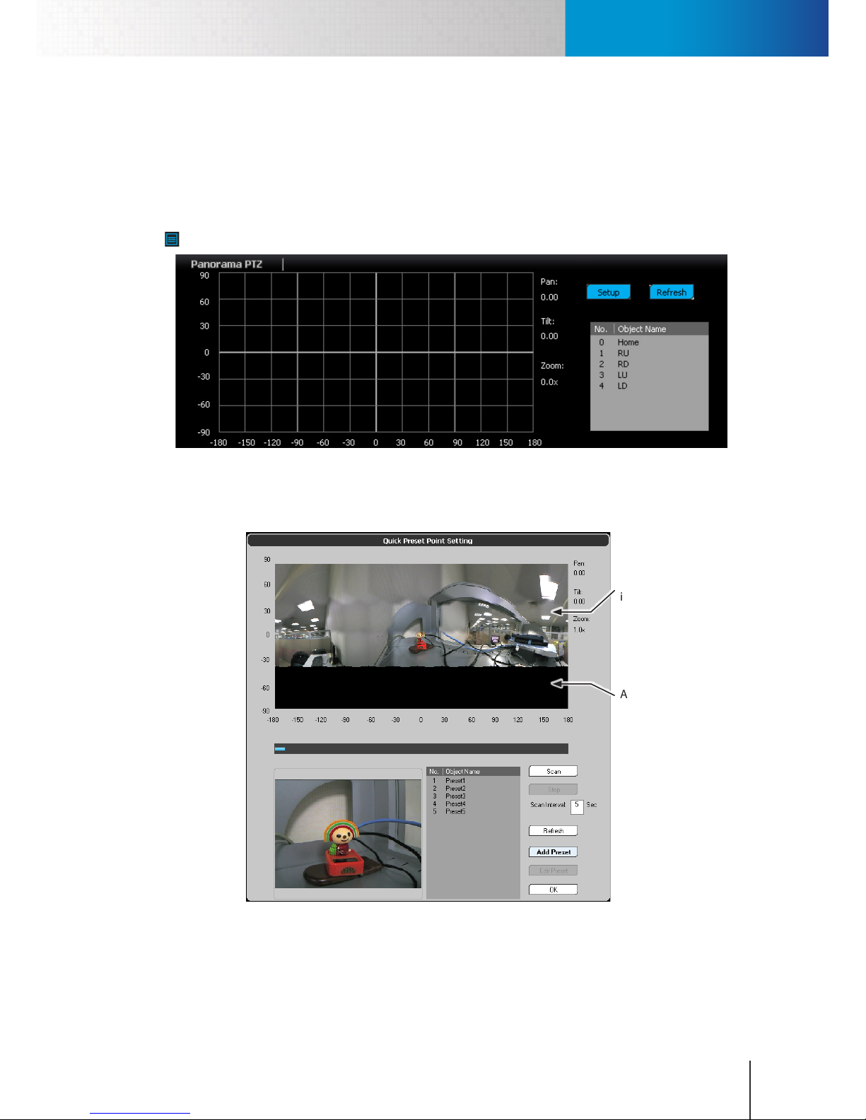
Panorama PTZ allows you to pan/tilt the camera simply by clicking on a panoramic camera image fused by
ComproView®. When the panorama PTZ mode is selected, a Panorama PTZ control panel will come up. Then
click the “Setup” button to congure PTZ function for the rst time (or click on the preset point setting icon
in the PTZ function panel).
Figure 4-7. Panorama PTZ panel
After that, hit “Scan” to make the PTZ camera scan the surrounding area within the camera’s pan/tilt range
and generate a panoramic picture.
Panoramic
image
Area beyond pan/
tilt coverage
Figure 4-8. Preset point setting window
After the camera nishes scanning the surrounding area, ComproView® will show a panoramic picture on the
coordinate grid. Areas out of your camera’s pan/tilt range will appear black on the panoramic picture of the
quick preset point setting window. You can click on any spot on the panoramic picture or click-and-drag a
Page 32
Detection Indicators
Compro RS-3232 - User's Manual
4-10
square to mark an area of interest on the panoramic picture, and then the camera will be steered to the new
position you have specied.
Additionally, depending on the quality of network connection, it may take a while for ComproView's pan/
tilt command to reach the PTZ camera which then moves to a new position. In the case of a slow camera
response to PTZ command, try increasing the scanning interval, which dictates how long the ComproView®
should wait for the PTZ camera to move to the next position in the scanning process.
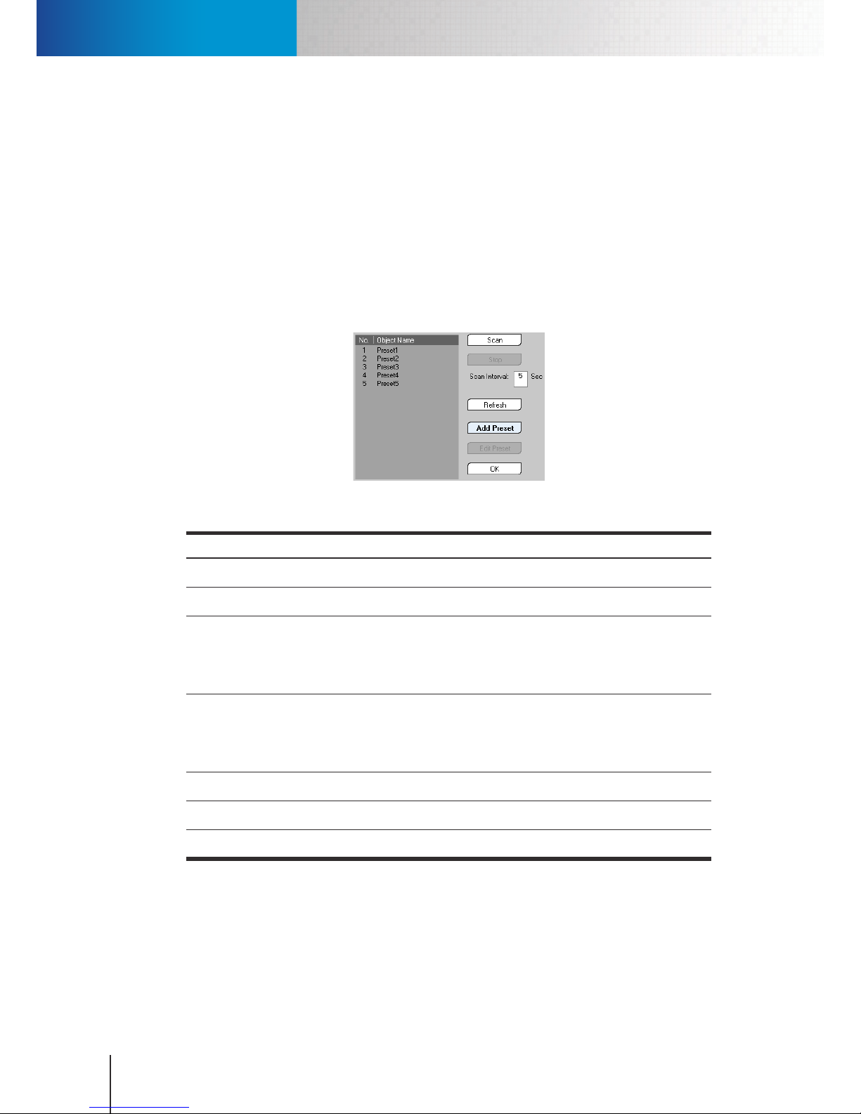
In the lower half of the Quick Preset Point Setting window you will nd a list of preset points with a couple of
options. The following are the descriptions of these options. You can Add and Edit Preset Points on the list. To
add a preset point, move your camera to a desired position and then hit “Add Preset”; then hit OK twice. You
can also double-click on any preset points on the list to quickly change camera position. The buttons next to
the list are explained below.
Figure 4-9. List of preset points
Item Description
Scan
Hit “Scan” to generate a panoramic picture.
Stop
Stop the scanning process
Scan Interval
Define how long ComproView® waits for the camera to move to the next
area to be scanned in the 360-degree (or less) eld of view. If the panoramic
picture generated is not satisfying due to camera's slow response to PTZ
command, try increasing the scan interval and then re-scan.
Refresh
Click to manually update the list of available preset points on the camera.
The preset points are stored in the camera system. Hitting the "Refresh"
button will force ComproView® to obtain the most up-to-date preset point
information from the camera through the network.
Add Preset
Click to add a preset point to the camera.
Edit Preset
This allows you to delete a preset point stored in the camera.
OK
Click to close the window.
Table 4-5. Preset point buttons
Detection Indicators
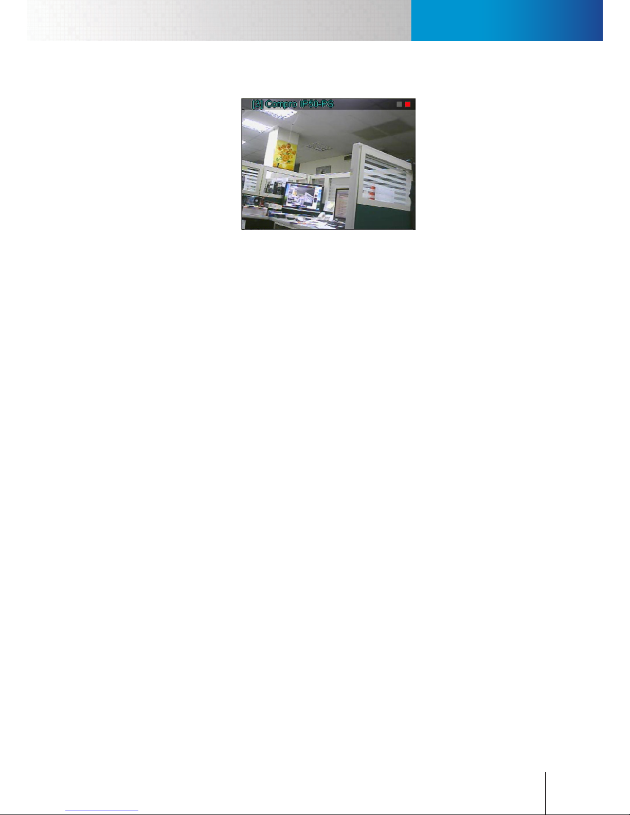
The following gure shows two dierent types of detection status (red indicator means detection is triggered
and green indicator means a standby), and you can see there are two indicators in each video pane (the left
indicator indicates all the available detection types other than Motion Detection, while the right one only
Page 33
Detection Indicators
Chapter 4: Main Workspace
4-11
indicates the status of Motion detection).
Figure 4-10. Detection Indicators
Page 34

Compro RS-3232 - User's Manual
4-12
Page 35
Assign New IP Address to RS-3232
Chapter 5: How to...
5-1
Chapter 5: How to...
In the following sections, you will nd the instructions on how to set up most frequently used functions or how to
perform common tasks in ComproView® on your RS-3232.
Assign New IP Address to RS-3232
Follow the steps below to assign a new IP address to the RS-3232.
1. Exit ComproView®.
2. Click the menu icon in the lower-left corner of the screen.
3. Choose “Control Panel” from the y-out menu, and then double-click “Network Connections.”
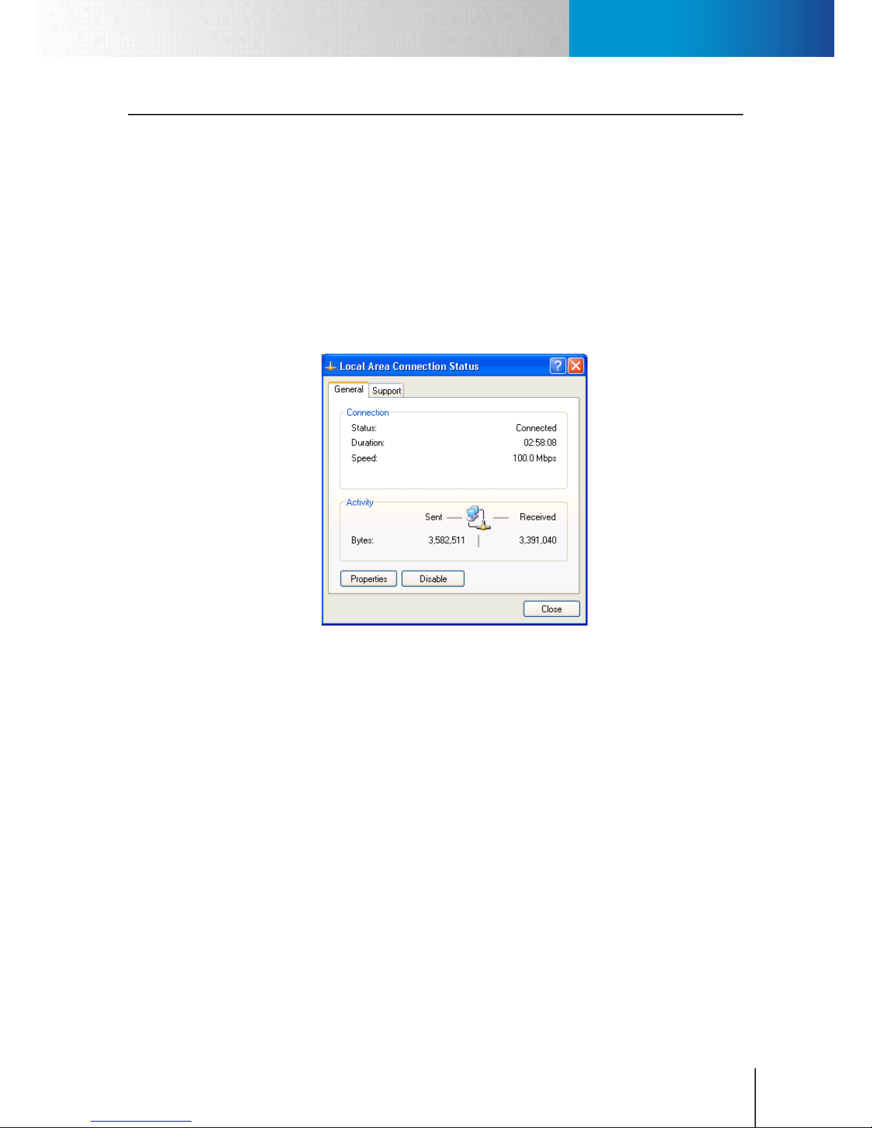
4. Double-click on the “Local Area Connection” icon. A connection status window will come up. Click on
“Properties” of that window.
Figure 5-1. Local Area Connection
5. A “Local Area Connection Properties” window pops up. Double-click “Internet Protocol (TCP/IP)” from a
list of items in this window.
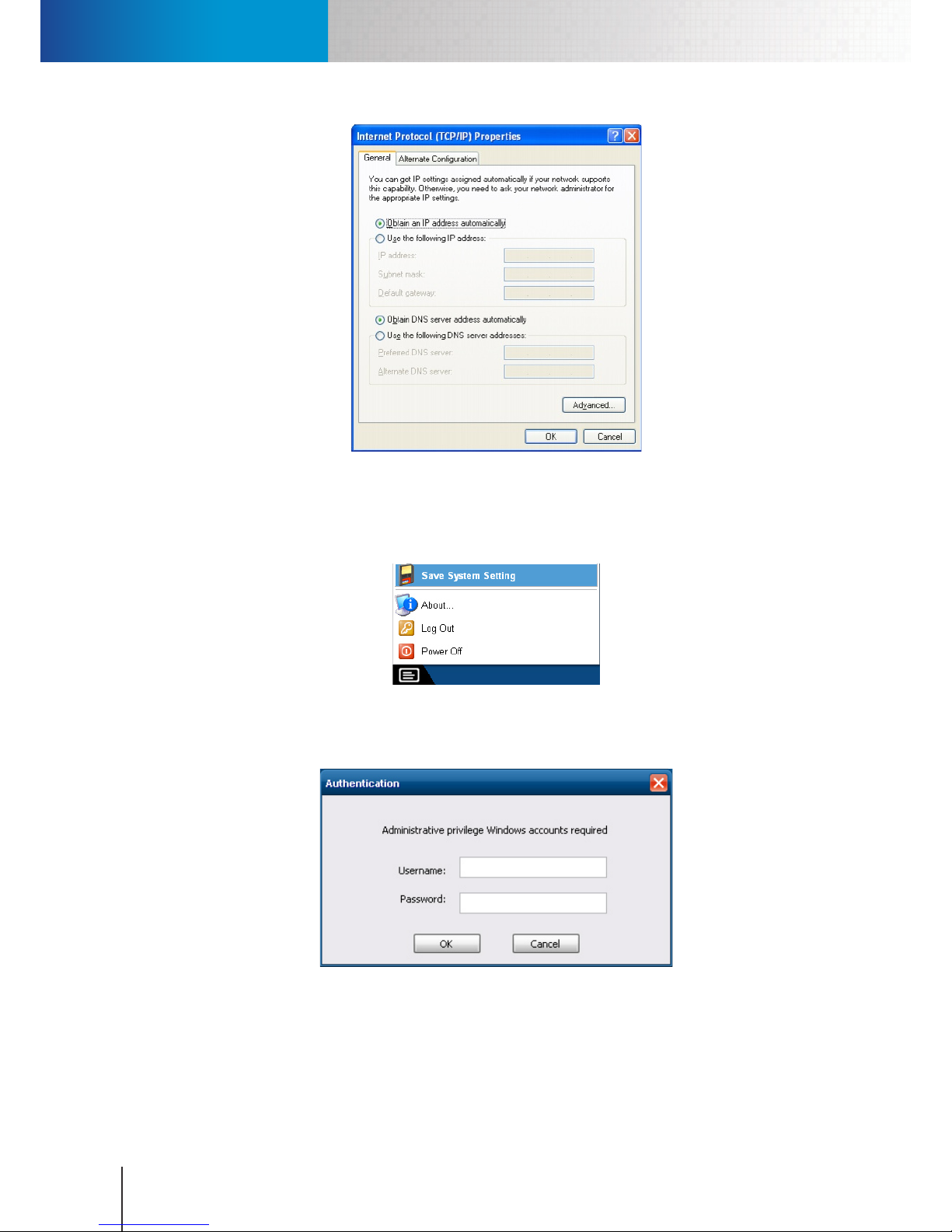
6. An “Internet Protocol (TCP/IP) Properties” window is opened. Choose “Use the following IP address,” and
then punch in a new IP address, subnet mask, and default gateway. Note if the unit and your IP cameras
are located on the same LAN network, ensure that they have the same subnet mask and gateway.
Page 36
Assign New IP Address to RS-3232
Compro RS-3232 - User's Manual
5-2
Figure 5-2. Assign IP address
7. Click “OK” twice to save the IP address changes.
8. Click on the menu icon in the lower-left corner of the screen again, and choose “Save System Setting”
from the y-out menu.
Figure 5-3. Save system setting
9. An “Authentication” window is displayed. Please enter the default user name “administrator” (skip
password), and then click on “OK”.
Figure 5-4. Authentication window
10. Choose “Yes” when asked whether to restart the system to complete the conguration.
Page 37
Add Cameras
Chapter 5: How to...
5-3
Add Cameras
After you have successfully logged into ComproView®, you can start to add cameras or video servers to the
system. There are several ways to add devices: using quick setup tool, using configuration console, using
right-click menu, and using channel control panel.
Using Quick Setup Wizard
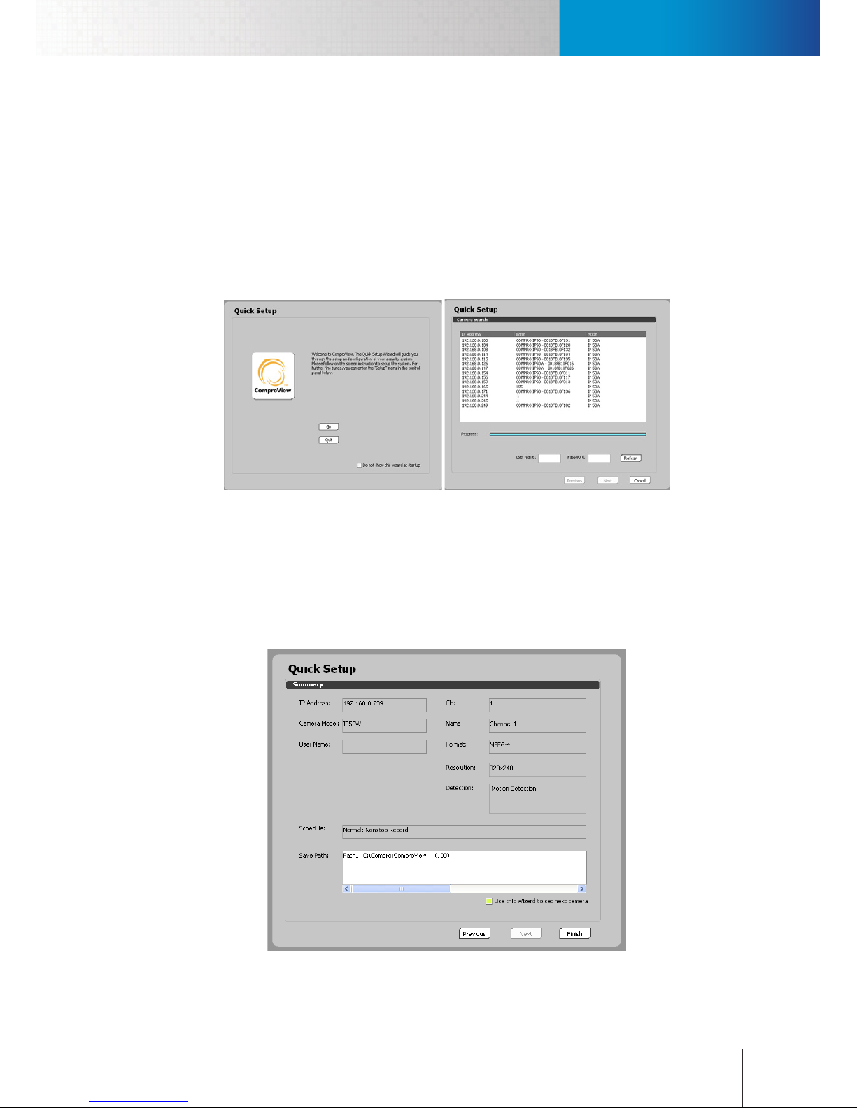
1. After a successful login to the ComproView® system (the default user name and password are both
“admin”), you will be greeted by the Quick Setup Wizard. Press [Go] and the Wizard will guide you
through the process of adding devices.
Figure 5-5. Quick setup wizard
When you see the “Camera Search” screen, please choose one camera you wish to set up, and then enter
its correct User Name and Password. Click “Next” when ready.
2. When you have reached the last step of the quick setup but still need to set up other cameras, please
check the “Use this Wizard to set next camera” option and press the nish button to continue with the
quick setup.
Figure 5-6. Setup summary
Page 38
Add Cameras
Compro RS-3232 - User's Manual
5-4
Press [Finish] when you see the summary page to complete the setup.
In addition, motion and audio detection and scheduled recording action you have configured for each
camera channel will only take eect and be started after you have clicked the “Start all ” icon (the icon
shall then turn red). When “Start All” button is not in red, the system will stay in passive viewing mode and
no alarms will be triggered.
Click to Start and
Stop All functions
Figure 5-7. Start and Stop All functions
Note:
Firstly, the “Start All” button affects all the camera channels. However,
you can also manually start the actions configured for each individual
channel via the “Start by Channel” option found in the system main
menu. Secondly, you will not be able to run system conguration ‘ such
as camera setup, channel setup, detection setup, etc., when you have
“armed” the system by clicking on the “Start/Stop All” icon. You must
“disarm” the system rst by clicking on the “Stop All” button. (Armed >>
system is monitoring; disarmed >> system stops monitoring.)
Using System Conguration Console
Should you wish to manually set up your camera, you can
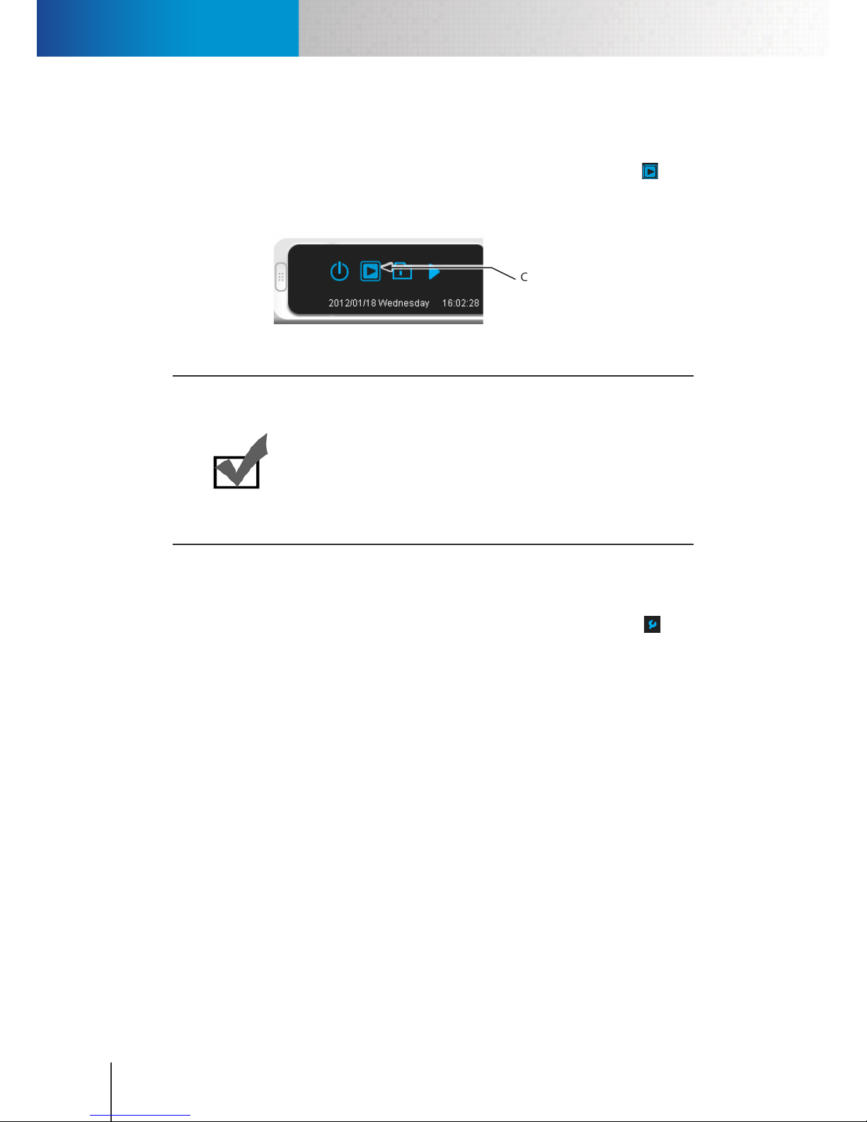
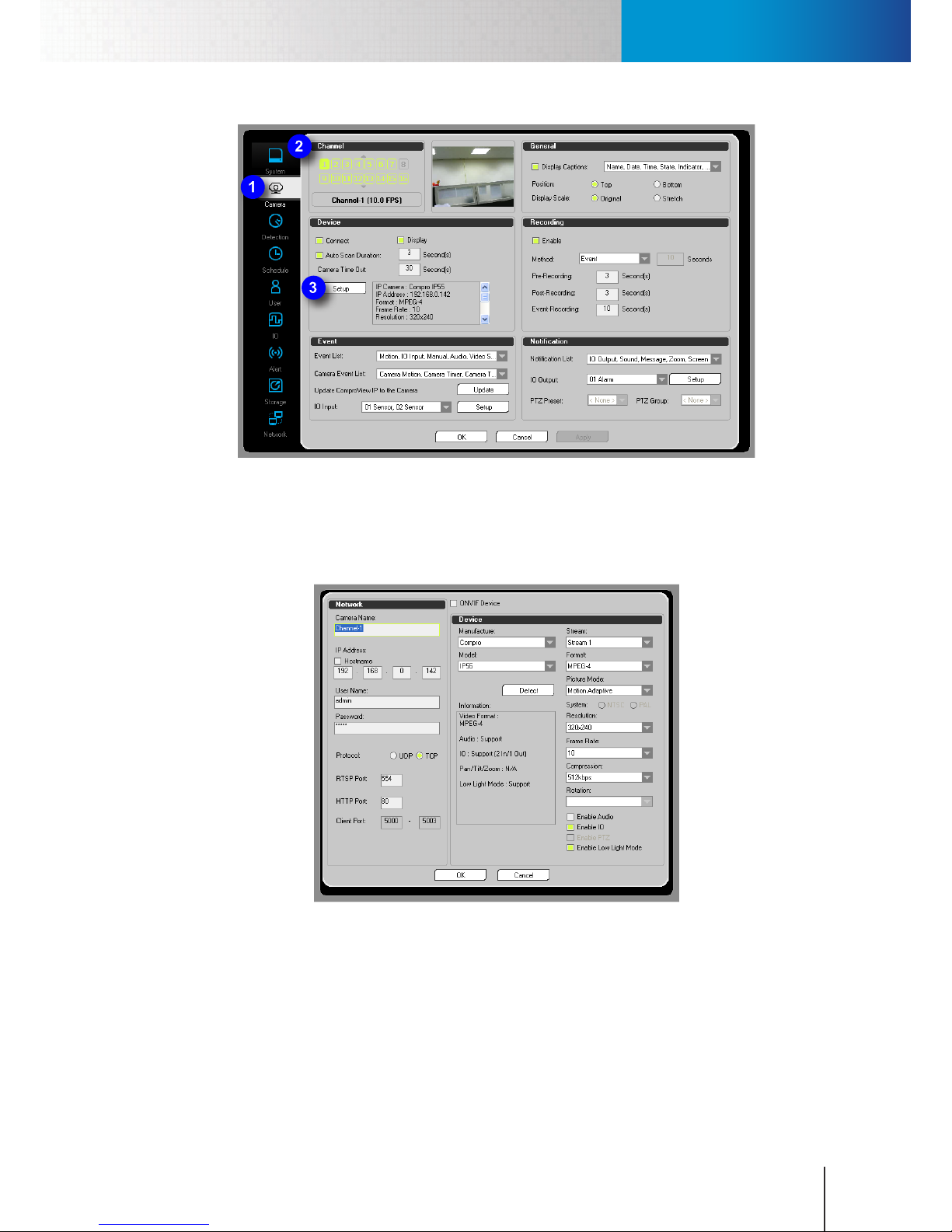
1. Click on the “Setup” button located in the system panel (represented by a wrench ). Upon hitting
the setup button, you will see a y-out menu with the option of "Setup". Select “Setup” and then the
system conguration console will appear.
2. Click the camera icon to go to the “Camera” tab. After that, click on the channel number you wish to
set up, and then press the “Setup” button in the “Device” section.
Page 39
Add Cameras
Chapter 5: How to...
5-5
Figure 5-8. Camera setup in conguration console
3. A camera setup window comes up when the channel you selected has been congured previously. To
add the IP camera manually, enter the camera name, correct IP address, user name and password for
your new camera to assign the camera to this channel. Or hit the “Detect” button to search for all the
IP cameras installed on your LAN network in case you don’t know your camera’s IP address.
Figure 5-9. Camera setup window
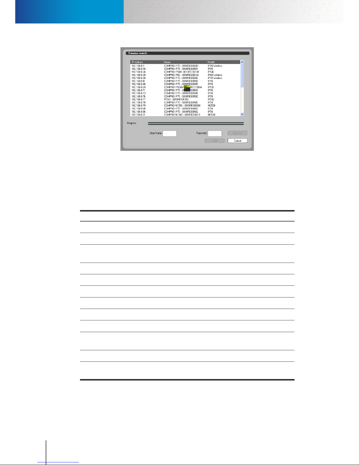
On the ip side, if the selected channel hasn’t been assigned to any IP device yet, the system will pop
up a camera search window immediately after you hit "Setup" in the previous step.
Page 40
Add Cameras
Compro RS-3232 - User's Manual
5-6
Figure 5-10. Camera search window
When the camera search window appears, select the camera you wish to add to the system from a list
of available devices on your LAN network. Then put in its user name/password, which are both “admin”
by default, and press “Add.”
4. After the IP camera is assigned to the specified camera channel in the system, the following items
remain congurable in the camera setup window.
Item Description
Manufacturer IP camera’s manufacturer
Model IP camera’s model number
Stream Determine which video stream to be used for live view/recording (depending on
camera support)
Format Video compression codec
Frame Rate How many pictures should be recorded per second
Resolution Video resolution
Compression Video quality which is dened by bitrate; higher bitrate leads to higher quality
Rotation Rotate the image by 180 degrees for ceiling mounted camera
Enable Audio Record audio stream
Enable IO
Enable the signal receiving from digital input sensor to control digital output
relay
Enable PTZ Enable the control of Pan/Tilt/Zoom if supported
Enable Low Light
Mode
Adjust exposure level to enhance picture quality when the ambient light is
insucient
Table 5-1. Fields in camera setup window
5. When ready, presses [OK] button to conrm the settings.
6. After the camera setup window is closed, press “Apply” to save the changes and then click “OK” to close
Page 41
Add Cameras
Chapter 5: How to...
5-7
the conguration console.
7. Afterwards, please wait for a while for ComproView® to establish connection with the camera. Then
you will be able to use other monitoring functions when the camera video is displayed.
Note when connecting to the IP camera for the first time, ComproView® will check the IP camera’s
rmware version to ensure compatibility. If the rmware version is older than what is required, you
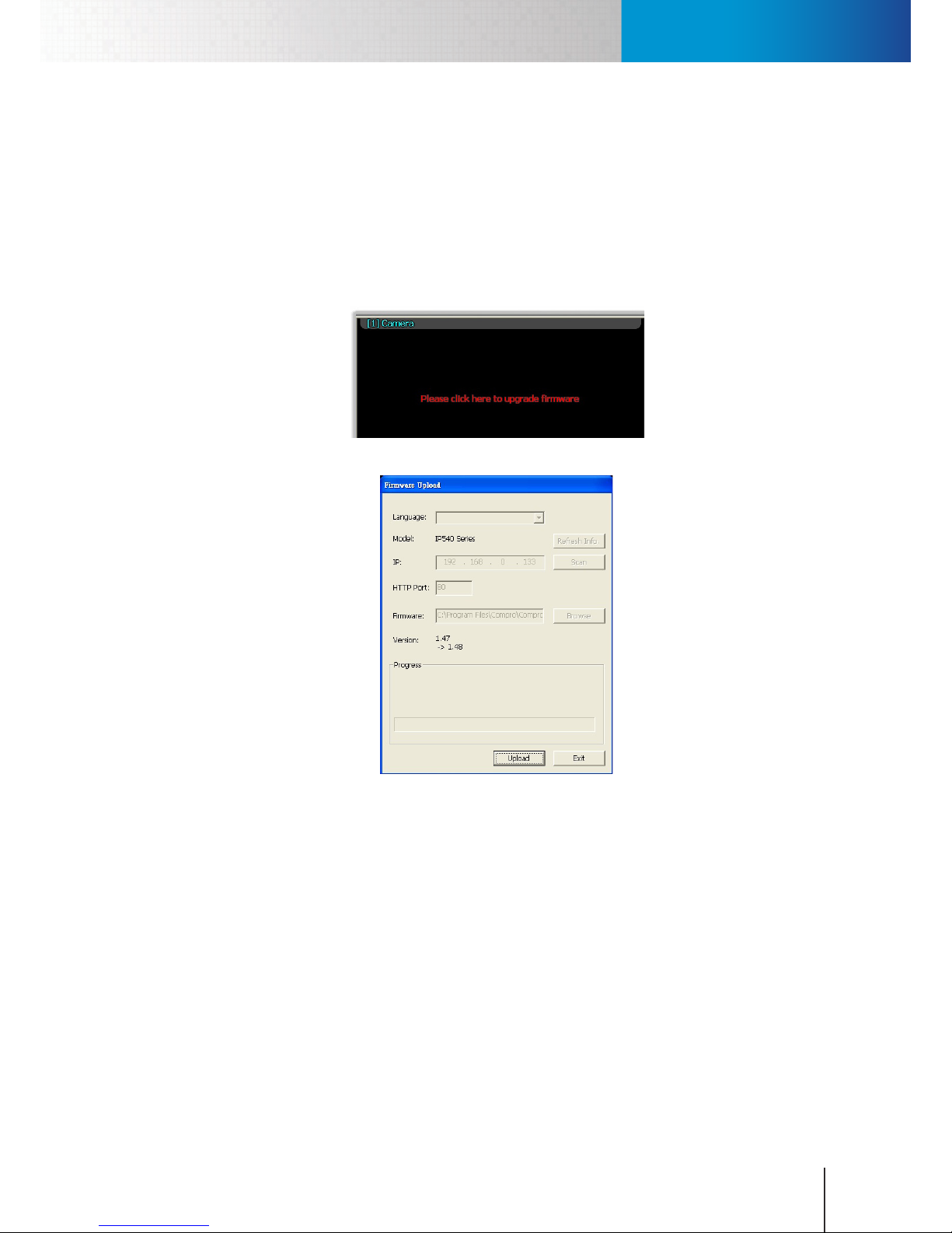
will be prompted to upgrade camera rmware. When a message saying "Please click here to upgrade
rmware" appears in the video pane, click on the video pane. A "Firmware Upload" window comes up.
Choose “Upload” to upload the latest rmware from your RS-3232 to the IP camera.
Figure 5-11. Firmware update prompt
Figure 5-12. Firmware uploader
Using the Right-Click Menu
1. After a successful login to the ComproView® system (the default user name and password are both
“admin”), you can right-click on any video pane/channel you wish to assign to your new IP camera.
2. A right-click menu then appears. Choose "Camera Setup" from the menu.
3. If the selected channel has not been congured before, a camera search window will come up. Select
your camera from the list and put in its correct user name/password, which are both “admin” by
default, and then press “Add” to complete the operation. On the contrary, a camera setup window will
come up when the channel you selected has been congured previously. In this case, put in all the
necessary information and then hit OK.
Page 42
Set Up Video Recording
Compro RS-3232 - User's Manual
5-8
Using the Channel Control Panel
1. After a successful login to the ComproView® system (the default user name and password are both
“admin”), bring up the channel control panel by clicking on a left arrow button (right next to the
system panel).
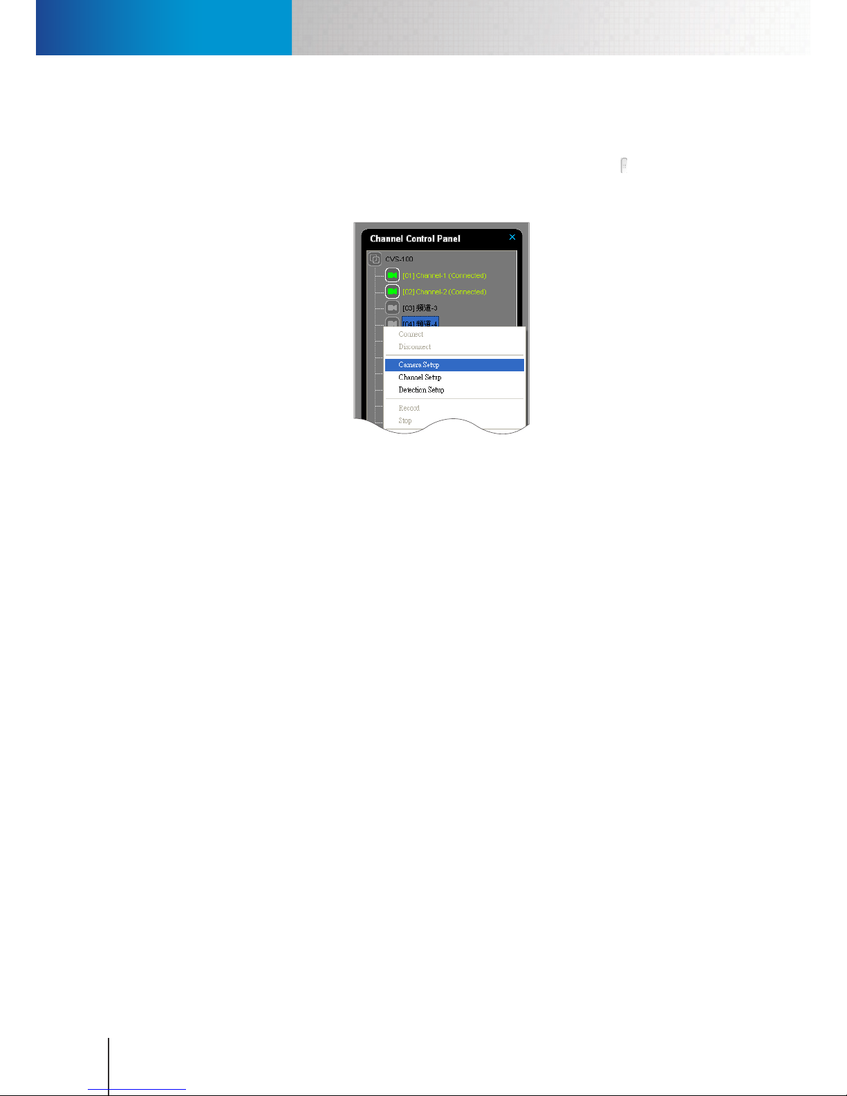
2. Up comes the channel control panel. Choose "Camera Setup" from the menu.
Figure 5-13. Camera setup via channel control panel
3. If the channel you right-clicked on has not been congured before, a camera search window will come
up. Select your camera from the list and put in its correct user name/password, which are both “admin”
by default, and then press “Add” to complete the operation. On the contrary, a camera setup window
will come up when the channel you right-clicked on has been congured previously. In this case, put
in all the necessary information and then hit OK.
Set Up Video Recording
Recording is an essential part of surveillance video management. You can select from four dierent types of
recording methods (Non Stop, Event, and Time Lapse). To set up recording for your IP camera:
1. Open “Setup” on the system conguration console and go to the Camera tab. Make sure your IP camera
is selected in Device section.
2. In the Recording section, click “Enable”, and choose the “Recording Method” (Non Stop, Event, Time
Lapse).
3. Make sure at least one type of detection is enabled and then dene the values for “Pre-R ecording”, “PostRecording” and “Event- Recording” duration if Event recording or Time Lapse recording is chosen.
4. Then, at the bottom of Camera tab, press “Apply” to apply the recording settings.
Schedule Video Recording
The “Schedule” tab of the system configuration console lets you schedule recording operations. Prior to
arranging your recording schedule, go to the “Camera” tab and set the recording preference for your camera
channel(s). The following is a scheduling example to arrange a daily non-stop video recording schedule
during oce hours.
Page 43
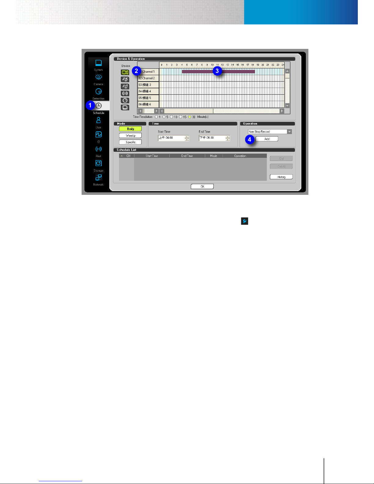
Play Recordings
Chapter 5: How to...
5-9
Figure 5-14. Schedule Video Recording
1. Enter the system conguration console by clicking on the setup icon () and then choose “Setup” from
the y-out menu.
2. Go to the “Schedule” tab.
3. Click on the channel number (row header) to choose a channel. The selected channel will be highlighted
in light blue.
4. Set Start/End Time in the Time section. You can also click on the timeline to set the start time, and then
drag the time bar to the point in time when you want the recording to end and then click again to set
the end time. To update your start/end time, simply click and drag on the timeline again.
5. Make sure “Non-stop Recording” is selected from the “Operation” drop-down list. Then, press “Add” to
add a new schedule.
6. Click [OK] to exit the conguration console.
Play Recordings
After some recordings have been made, you can use the Playback console to search for and play back your
recordings. Follow the steps below to play back your recordings.
Page 44
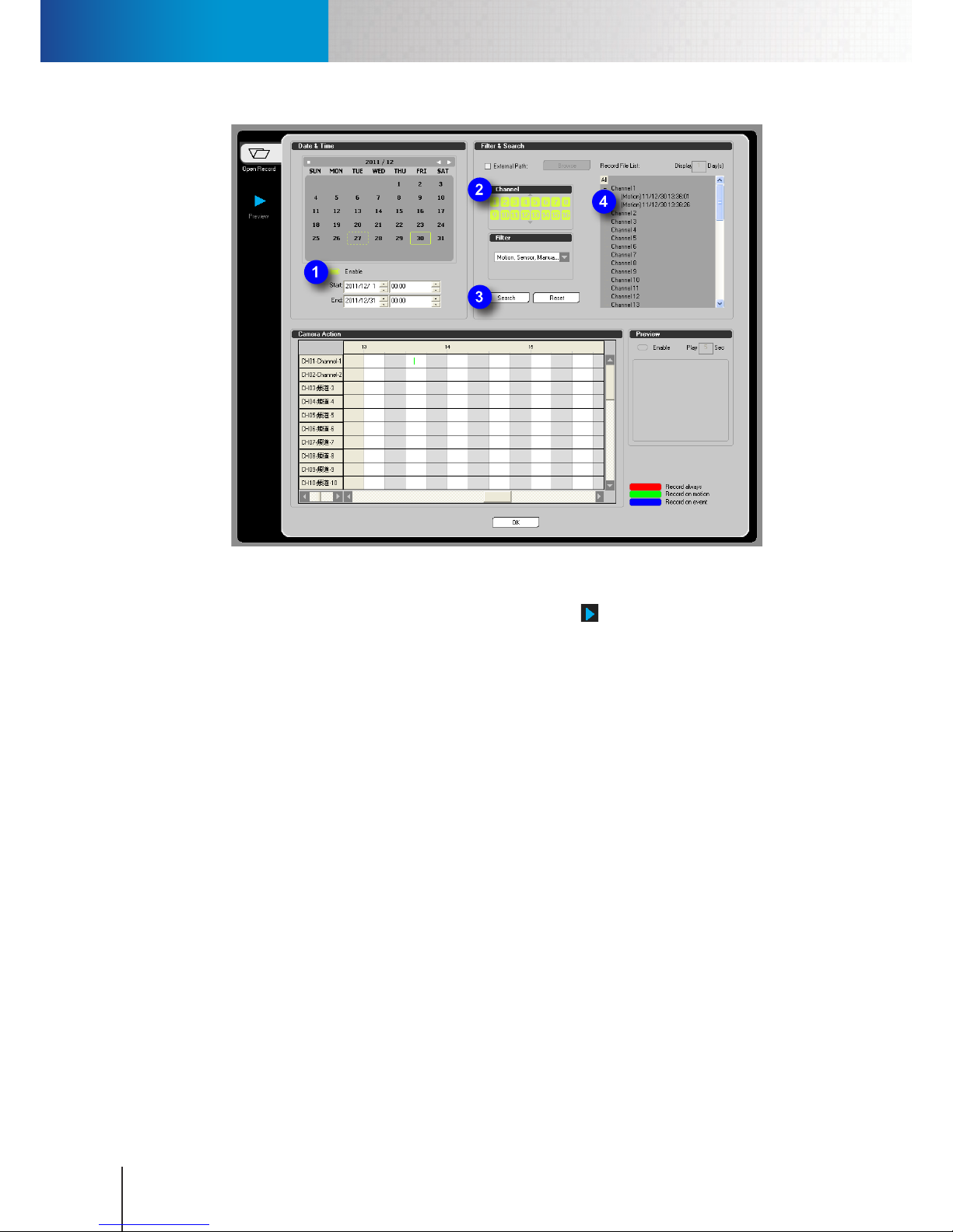
Play Recordings
Compro RS-3232 - User's Manual
5-10
Figure 5-15. Play back recordings
1. Bring up the Playback console by clicking on the Playback icon ( ).
2. Up comes the playback console. If you like to specify a time period to search for recordings, check
"Enable" option in the Date & Time section and dene the start time and the end time. Otherwise leave
the "Enable" option unchecked to search all the recordings in the system.
3. In the Channel section, select the channels you want to search.
4. In the Filter section, click on the combobox and then choose the event types you want to search for.
5. Hit the "Search" button, and ComproView® will display a list of recordings that match your search criteria.
6. From the "Recorded File List" in the upper-right corner, double-click on any of the recordings found to
start playing back.
ComproView® automatically switches to the Preview tab after you double-click on a video recording on the
"Recorded File List", as the following gure shows.
Page 45
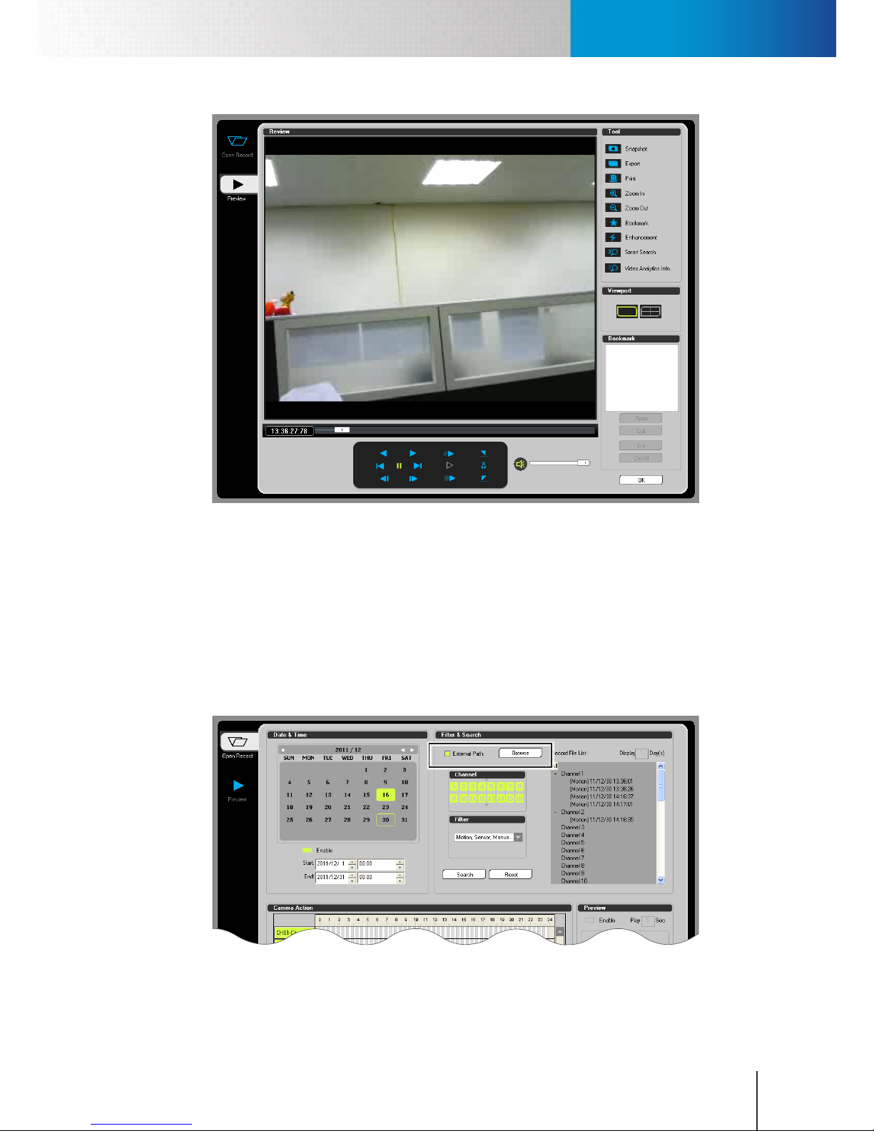
Play Recordings
Chapter 5: How to...
5-11
Figure 5-16. Preview tab
You can drag the seek bar to any position to start playing from that selected point. Hover the cursor on any
playback button below the video pane and you will see its function. To exit the playback console, hit the OK
button.
Play Back from Backup
You can play back the video recordings backed up to other locations. To do so, check the “External Path”
option under “Filter & Search”, and hit the “Browse” button to locate the folder on your PC that contains
the backup les. Then, press “Search”, and if any results turn up, double-click on an item on the list to start
playback.
Figure 5-17. Use external path
Page 46
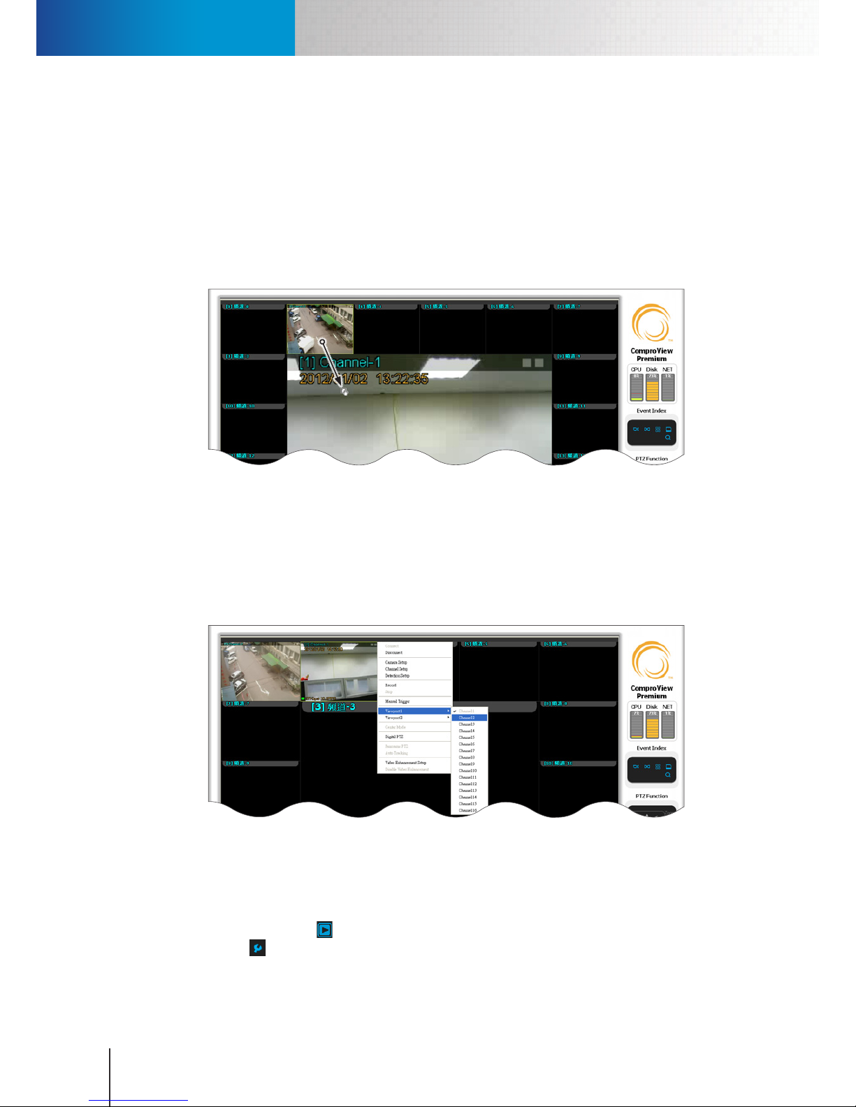
Customize Viewport
Compro RS-3232 - User's Manual
5-12
Customize Viewport
The following section describes how to customize the channel order in the video window using either dragand-drop or viewport right-click menu.
Drag-and-Drop
You can click and drag on any given video pane to change its location in the video screen. For instance, to
switch the location of channel-2 with that of channel 1 (as illustrated below), you can click and hold the
mouse button on the channel-2 video pane, and then drag it to the channel-1 video pane and release the
button. That way, channel-2 will switch from upper-left video pane to the middle video pane.
Figure 5-18. Click and drag video pane
Viewport Right-Click Menu
Alternatively, you can right-click on any given video pane to invoke the viewport right-click menu and
change channel location in the video screen. To do so, simply right-click on a video pane and then choose
"Viewport 1" or "Viewport 2" from the menu and go ahead and select a new channel number. After that,
the video channel you right-clicked on will have its location switched with that of the channel you chose
from the viewport right-click menu.
Figure 5-19. View port right-click menu
Set Up Email Alert Messaging
To set up E-mail alert messaging function in ComproView®:
1. Ensure that the “Start all ” icon is not in red. Enter the system conguration console by clicking on the
setup icon () and then choose “Setup” from the y-out menu.
2. Go to the “Alert” tab.
Page 47
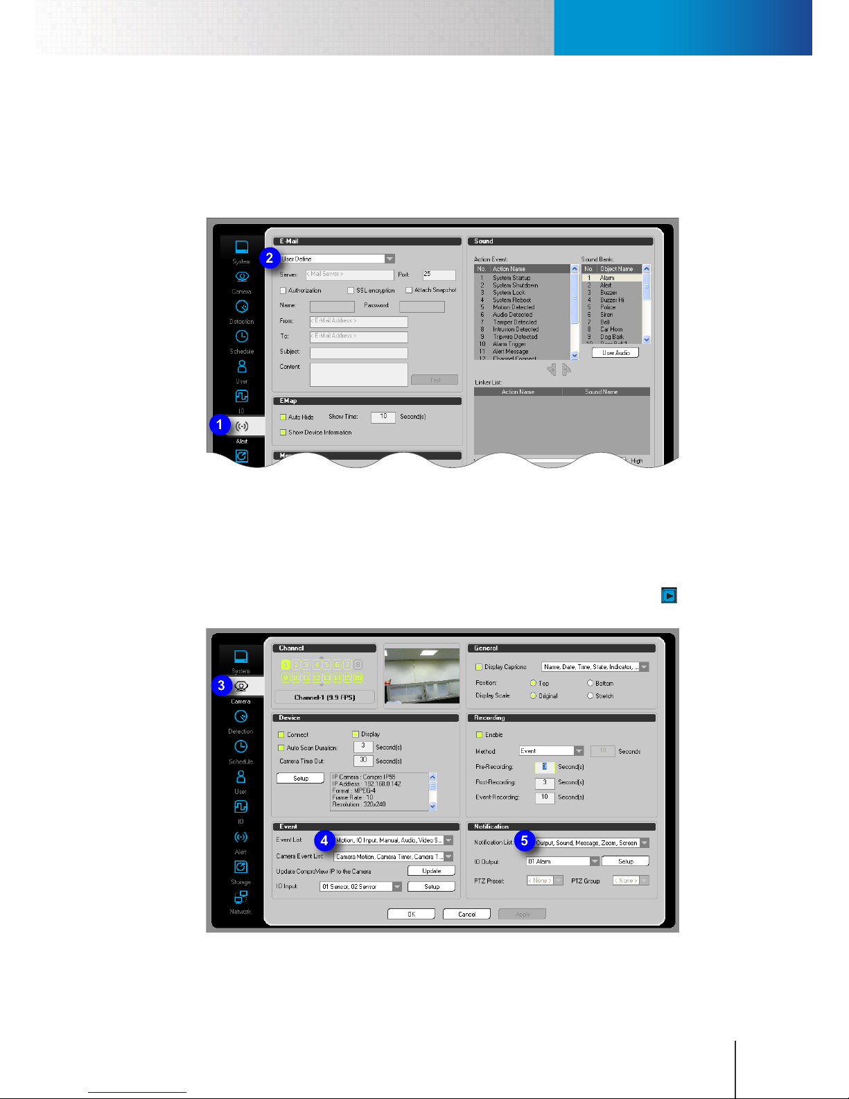
Set Up Email Alert Messaging
Chapter 5: How to...
5-13
3. In the E-mail section, click on the drop-down combo box and select a service between Google Mail and
Hotmail, or choose "User Dened" to use a dierent E-mail service and then manually enter the server
address, user name, password provided by your E-mail service provider.
4. Type in the sender and recipient information, as well as the E-mail subject and content.
5. Push the "Test" button to verify your setting.
Figure 5-20. Test Email sending
6. Go to the “Camera” tab.
7. In the Event section, click on the "Event List" drop-down combo box and check your event types. Then
click on the "Notication List" drop-down combo box in the Notication section and make sure E-mail is
checked.
8. Click [OK] to exit the conguration console. After setup is complete, click on the “Start all ” button,
which shall then turn red, to begin monitoring.
Figure 5-21. Set up camera notication
Page 48
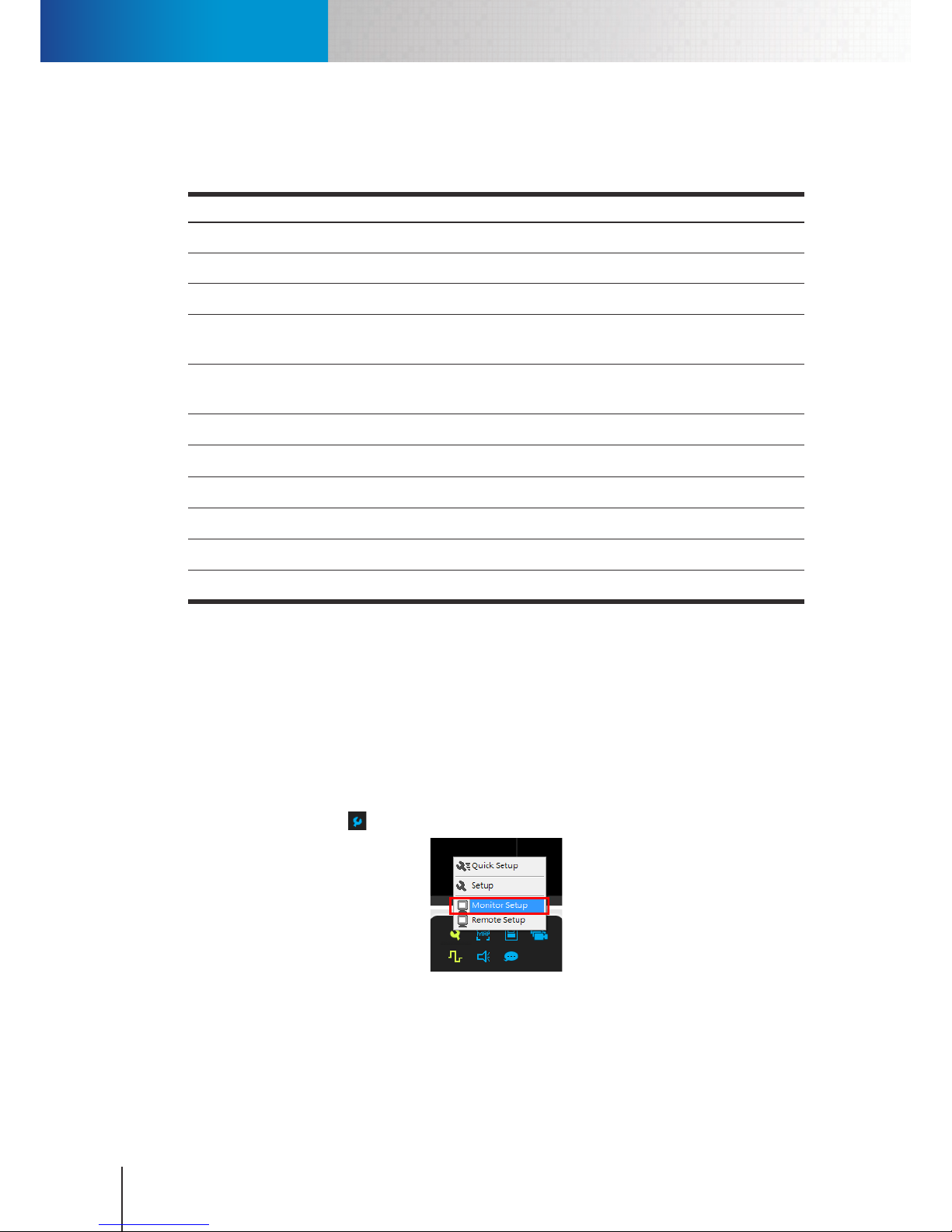
Set Up Multiple Monitors
Compro RS-3232 - User's Manual
5-14
E-mail
The following table explains the information you need to furnish in order to complete the E-mail alert
setup.
Item Description
Enable Enable/disable E-Mail notication.
User Dened The E-mail notication support SMTP, Google and Hotmail, please select it from the list.
Server
Enter E-mail server information.
Authorization If E-mail server requires authorization, activate this option to enter the necessary
account information (Name and Password).
SSL
encryption
If you server provides the SSL encryption, you can check here.
Attach le Enable to attach a snapshot with the E-mail.
From Enter the E-mail “from” address.
To Enter the E-mail “to” address.
Subject Enter the E-mail subject.
Content Enter the content of the E-mail.
Test Test E-mail information right now (send out E-mail).
Table 5-2. Email information
Set Up Multiple Monitors
You can use the Monitor Setup function to congure multi-monitor display if you have two or more monitors
at hand. The benefit of using two monitors is that it allows you to use one monitor to display the first 16
channels (or any given number) while using the other one to display the rest of the channels.
To set up multiple-display in ComproView®, you must rst enable the multiple-display mode in the display
settings of the RS-3232's Windows operating system. After that, follow the steps below:
1. Click on the setup icon (
) in the utility panel
and then choose “Monitor Setup” from the y-out menu.
2. Up comes a "Monitor Setup" window. Click on the number 2 button to congure the second display and
then go ahead and check the "Enable" checkbox.
Page 49
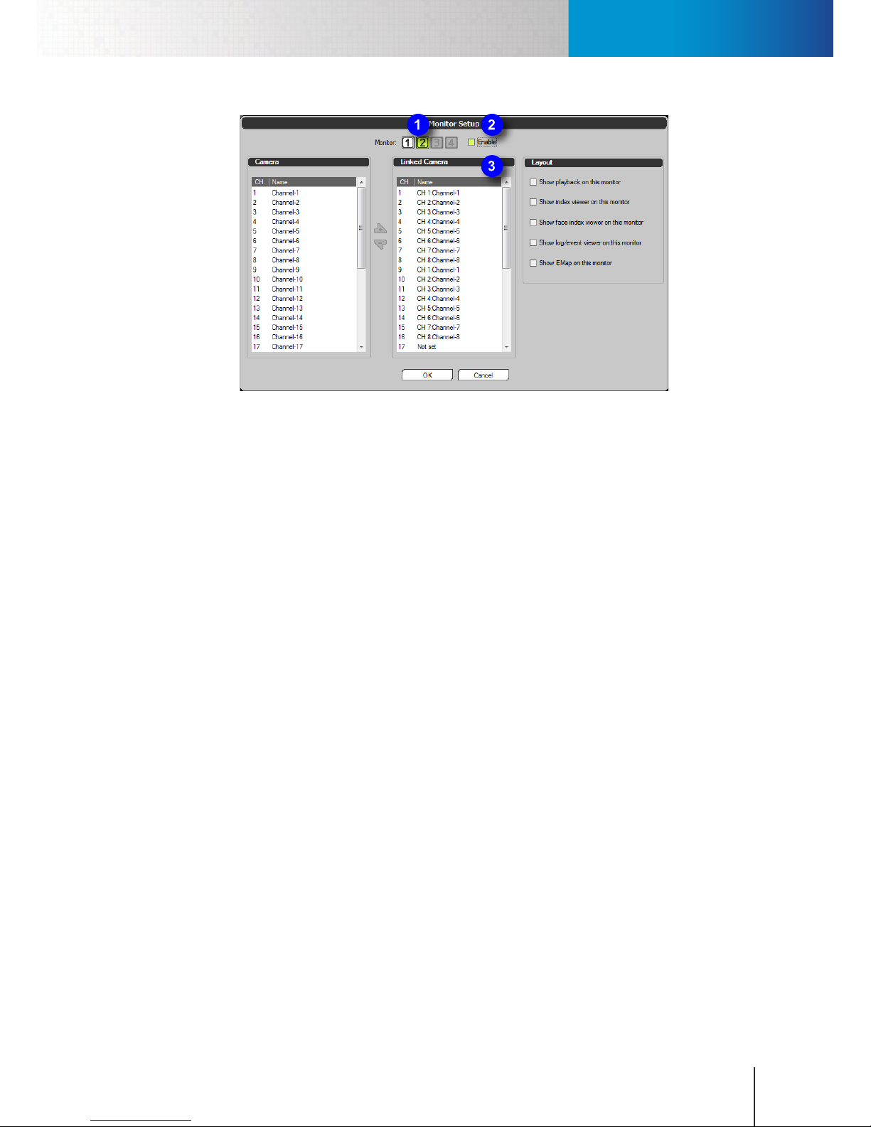
Set Up Event-based Recording
Chapter 5: How to...
5-15
Figure 5-22. Multiple-display
3. From the Camera list on the left-hand side of the Monitor Setup window, select the channels you wish
to be displayed on the second monitor. Then click the "plus" button to add those channels to the list of
"Linked Camera". Note that you can select a consecutive group of channels by clicking the rst channel,
holding down the shift key, and then clicking the last channel.
4. When desired, check the options in the Layout section to customize ComproView® workspace on the
second monitor. Then hit the OK button to complete the setup.
Set Up Event-based Recording
As an alternative to Non-Stop recording, you can use event-driven recording to save disk storage space. Such
as a recording operation initiated by detected motion in the scene or detected audio. To set up an eventbased recording:
1. Bring up the system conguration console by clicking the “Setup” icon. Click the camera tab and select
“Event” from the drop-down list as the recording method.
2. Set the amount of Pre-Recording time which determines the number of seconds to record BEFORE an
event is detected by the system. The event types include motion, audio, etc.
3. Set the amount of Post-Recording time which dictates the number of seconds to record AFTER a
detected event stops. The event types include motion, audio, etc. If after the system has started
recording for one event, and during the recording session, a second event is triggered, the postrecording will only begin when the event-recording for the last event stops.
4. In the Event-Recording field, fill in the number of seconds to record immediately AFTER an event is
triggered. Here it does not control the video recording length for a motion event. The system begins
recording when a motion event starts, and stops recording when this motion event stops. For events
other than motion, the total number of seconds to be recorded equals the amount of Pre-Recording
time, the amount of Event-Recording time, and the amount of Post-Recording time. If after the system
has started recording for one event, and during the recording session, a second event is triggered, then
from the time point of the second event’s occurence, the video recording length will be extended for the
number of seconds specied here.
Page 50
Set Up Event-based Recording
Compro RS-3232 - User's Manual
5-16
Note:
Each time a dierent motion/audio/IO event is triggered after the system
has started recording one event, the event recording timer is reset.
Page 51
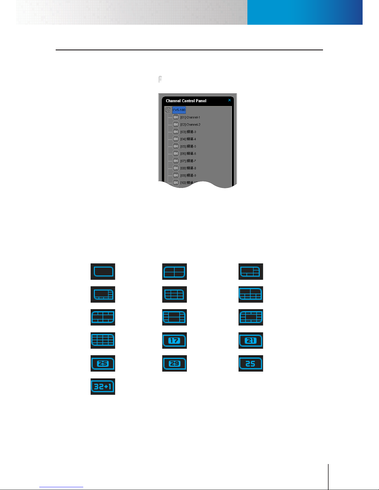
Channel Control Panel
Chapter 6: Live Monitoring
6-1
Chapter 6: Live Monitoring
Channel Control Panel
Channel control panel oers a quick way to navigate between dierent channels. The panel can be brought
up by clicking on a left arrow button (right next to the system panel). From the channel control panel, you
can control many of the advanced functions of a camera channel by right-clicking on a camera channel.
Figure 6-1. Channel Control Panel
Manage Video Pane Layout
Video Screen Layouts
There are dierent video screen layouts available in the main workspace. The following buttons show the
available video screen layouts in ComproView®. You can click on any of the following button to change the
video screen layout.
1 x 1 Layout 2 x 2 Layout 6-Channel
Layout
8-Channel
Layout
3 x 3 Layout 10-Channel
Layout
10-Channel
Layout
10-Channel
Layout
13-Channel
Layout
4 x 4 Layout 17-Channel
Layout
21-Channel
Layout
25-Channel
Layout
29-Channel
Layout
5 x 5 Layout
32-Channel
Layout
Drag-and-Drop
You can click and drag on any given video pane to change its location in the video screen. For instance, to
switch the location of channel-2 with that of channel 1 (as illustrated below), you can click and hold the
mouse button on the channel-2 video pane, and then drag it to the channel-1 video pane and release the
Page 52
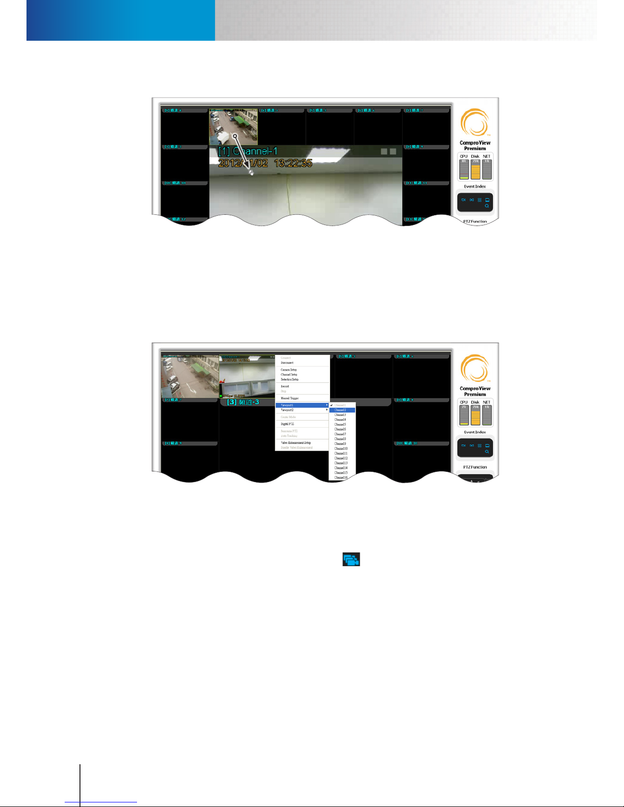
Group Cameras
Compro RS-3232 - User's Manual
6-2
button. That way, channel-2 will switch from upper-left video pane to the middle video pane.
Figure 6-2. Click and drag video pane
Viewport Right-Click Menu
Alternatively, you can right-click on any given video pane to invoke the viewport right-click menu and
change channel location in the video screen. To do so, simply right-click on a video pane and then choose
"Viewport 1" or "Viewport 2" from the menu and go ahead and select a new channel number. After that,
the video channel you right-clicked on will have its location switched with that of the channel you chose
from the viewport right-click menu.
Figure 6-3. View port right-click menu
Group Cameras
The camera group function allows you to always show live video from a selection of channels at the same
time. To group cameras, click on the camera group button in the utility panel to show the y-out menu
that contains the following items.
• Group Launch: Group the channels on a group list, so the video panes of those channels will be displayed
together in the video screen.
• Group Cancel: Ungroup the channels.
• Group Setup: Open the Group Setup panel.
Group Setup Window
After you choose "Group Setup" from the camera group menu, a camera group window will come up. To
create a new camera group:
1. Type a group name into the group name eld and then hit the plus button.
Page 53
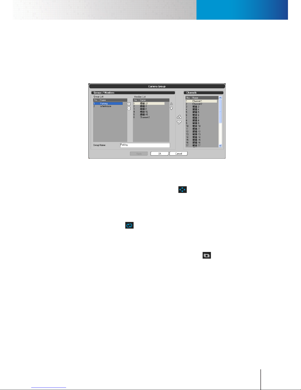
Full Screen Mode
Chapter 6: Live Monitoring
6-3
2. From a list of channels in the "Channels" section, select a channel and hit the "Add Member" button to
add the channel to the new group.
3. Repeat the previous step to add all the other channels you like to view together as a group to the new
group.
4. When ready, click [OK] to complete setup. The new group will then appear in the camera group y-out
menu.
Figure 6-4. Camera group window
Full Screen Mode
To switch to full screen view, click on the full screen view button in the viewport panel. To exit the full
screen view, press ESC key.
Auto Scan Mode
The auto scan mode allows you to view all the connected camera channels consecutively. To enable auto scan
mode, click on the Auto Scan button in the viewport panel. ComproView® will then
rotate through all the
connected camera channels in the video window.
Take a Snapshot
Click on any video pane to select a channel, and then hit the Snapshot button in the viewport panel. A
Windows "Save As" window will then appear. Navigate to your preferred folder, enter a le name, and then
choose "Save" to save the snapshot.
Manual Recording
To manually start recording live video on a particular channel, simply right-click on the video pane of the
camera channel you wish to record, and then choose "Record" from the right-click menu. The red "REC"
text appear on the selected video pane, indicating video is being recorded on this channel. Once manual
recording is started, ComproView® will continue the recording as long as the disk space does not run out. To
stop recording, simply right-click on the video pane again and choose "Stop" from the right-click menu.
Page 54
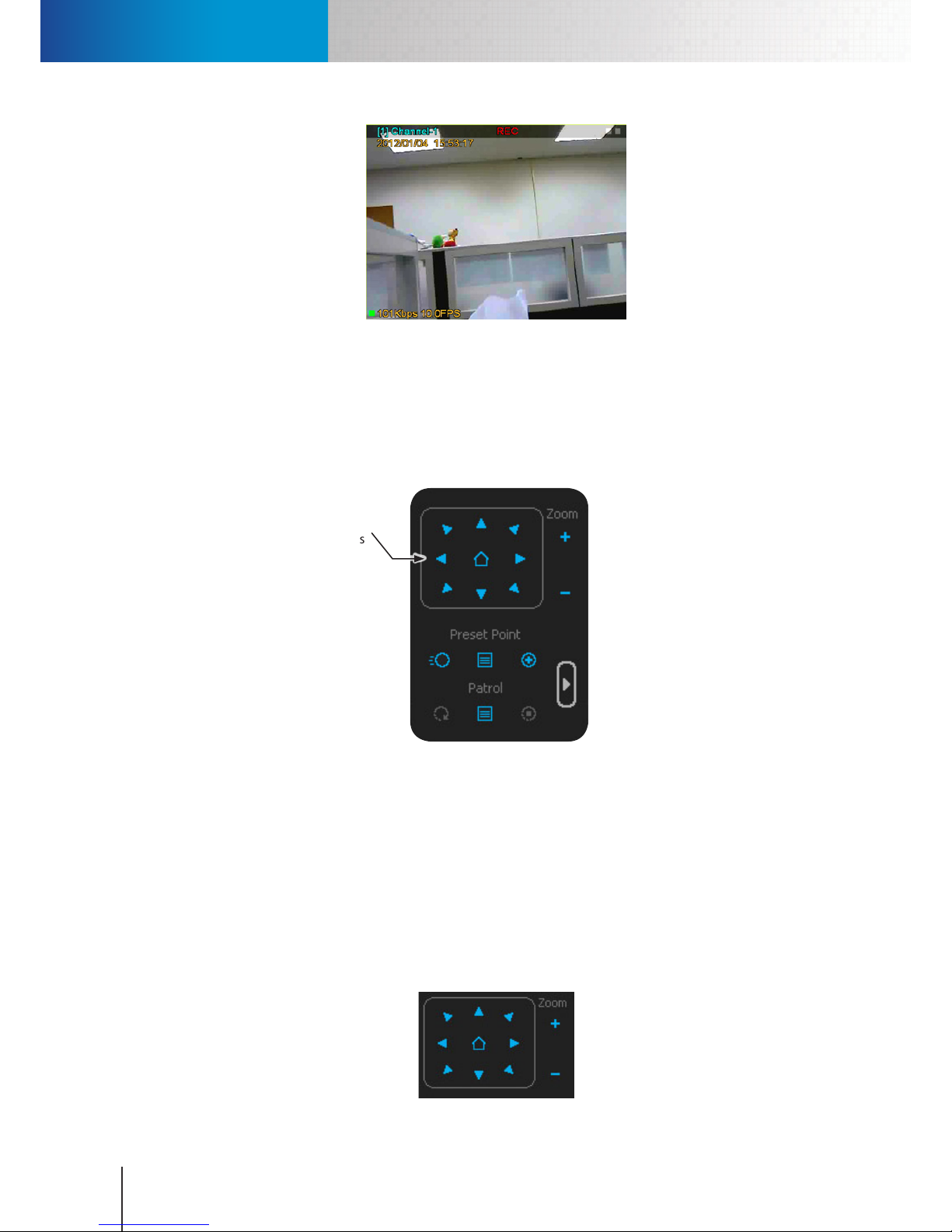
PTZ Control
Compro RS-3232 - User's Manual
6-4
Figure 6-5. Manual recording
PTZ Control
When you have connected a PTZ camera to ComproView®, you can pan, tilt, or zoom in and zoom out your
PTZ camera with the directional buttons and zoom buttons in the PTZ function panel, which is located next
to the video window. The buttons in PTZ function panel are inaccessible until you have selected a camera
channel connected to a PTZ camera, such as a Compro IP540.
Directional
buttons
Figure 6-6. Directional buttons
The same PTZ control buttons are also used in digital PTZ mode.
Digital PTZ
To enable the Digital PTZ function on a particular channel, right-click on any given video pane and choose
"Digital PTZ" from the right-click menu. Then the zoom control buttons under PTZ Function will become
accessible. To digitally zoom in and out, click “+” or “-” or place your cursor on the selected video pane and
scroll up/downon the selected channel. To pan/tilt, use the direction buttons or simply click and drag on
the channel pane being selected.
The digital PTZ function works for network cameras with either xed lens or vari-focal lens.
Page 55
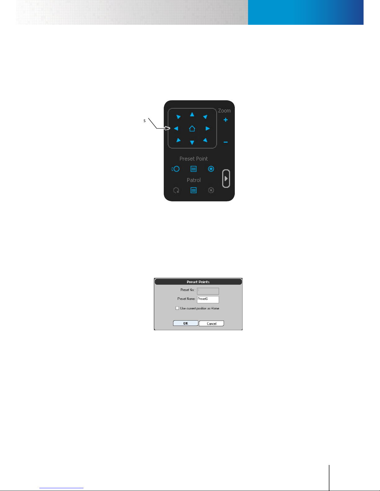
PTZ Control
Chapter 6: Live Monitoring
6-5
Preset Points
Using preset points allows you to quickly steer your PTZ camera to dierent pre-dened positions. Preset
point buttons are composed of a "Go to Preset Point" button (for moving PTZ camera to the selected preset
position), a "Preset Point Setting" button (for bringing up the quick preset point setting window) and an
"Edit Preset Point" button (for adding new preset points or edit existing preset points).
Directional
buttons
Figure 6-7. Directional buttons
1. To add a preset point:
2. Move your PTZ camera to a preferred position using the directional buttons.
3. Click the plus button under preset point. A y-out menu will appear.
4. Choose "Add" from the y-out menu.
5. Up comes a "Preset Points" window.
6. Enter the name of the new preset point. Check the "Use current position as Home" checkbox when
you want to update the home position of this PTZ camera.
7. Hit OK to add the preset point. The new preset point setting will be updated to the PTZ camera over
the network.
Center Mode (for PTZ Camera Only)
Besides using the directional buttons in the PTZ function panel to pan/tilt your camera, you can also use
the Center Mode. When enabled, the mode allows you to change the center of view by placing your cursor
on any spot within the selected video pane and then making a mouse click. After you've made a mouse
click, ComproView® will automatically control the pan/tilt of the camera to make the point you click on the
new center of view. To pan/tilt your PTZ camera using center mode:
1. Connect a PTZ camera, such as a Compro IP540, to the ComproView®.
Page 56
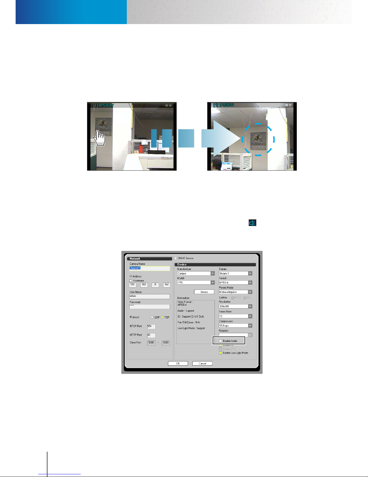
Audio Control
Compro RS-3232 - User's Manual
6-6
2. Right-click on the video pane of your PTZ camera channel.
3. Choose "Center Mode" from the right-click menu.
4. Click on any spot on the video pane of your PTZ camera. ComproView® will then automatically steer
the PTZ camera (within the camera's pan/tilt range) to make the spot you have clicked on the new
center of view of this channel. (To disable the center mode, right-click and choose "Center Mode"
again.)
Figure 6-8. Center mode
Audio Control
If your IP camera connected to ComproView® supports audio (with internal/external microphone), you can
make ComproView® receive, record, and play back audio data together with video data from your IP camera.
Camera audio in ComproView® can be toggled on/off using a speaker icon ( ) in the utility panel. But
before you can use the audio control, you must enable audio stream from you camera. To do so, right-click on
a connected camera channel and choose "Camera Setup." After that a camera setup window will come up as
the below gure shows.
Figure 6-9. Enable audio stream
Having enabled the audio stream, you can then toggle the reception of audio data in ComproView® by
clicking on the speaker icon when monitoring live camera video. When the speaker icon turns yellow and you
click on a video pane, ComproView® will play the sounds picked up by the microphone of the IP camera you
selected, whereas a blue speaker icon indicates no sounds from all camera channels.
Page 57
Talk and Broadcast Voice
Chapter 6: Live Monitoring
6-7
Talk and Broadcast Voice
If your IP camera connected to ComproView® is equipped with a speaker, you can speak into the microphone
connected to the RS-3232 and broadcast your voice through your camera's speaker or audio line out. To begin
broadcasting your voice over the network, click and hold the Talk button ( ) in ComproView®'s utility panel
and then start speaking into your microphone. Relase the Talk button when your are done. If you single-click
the Talk button, ComproView® will allow you to broadcast your voice for approximately 5 seconds.
Note:
When using the Talk function, you may experience various degrees
of delay between transmission from the computer and playback
on the camera end depending on the condition of your network
environment.
Page 58

Talk and Broadcast Voice
Compro RS-3232 - User's Manual
6-8
Page 59
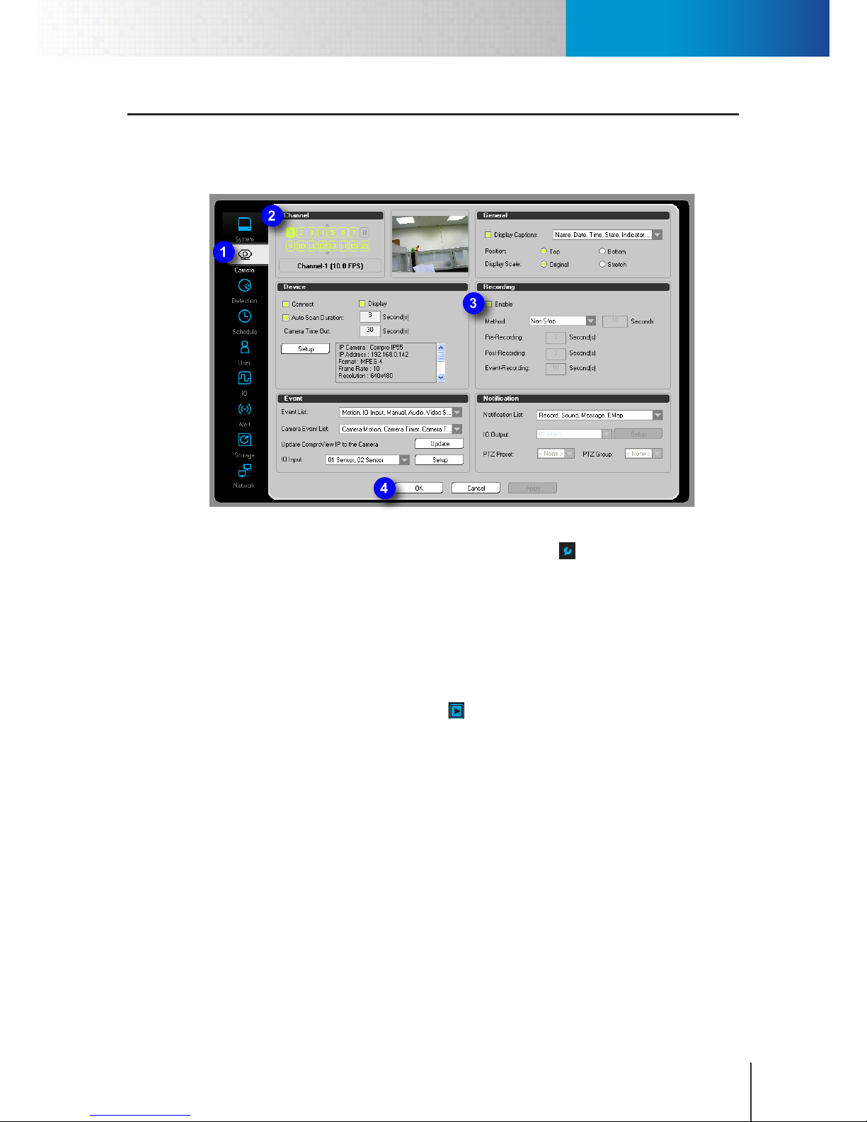
Set Up Non-Stop Recording
Chapter 7: Recording
7-1
Chapter 7: Recording
Set Up Non-Stop Recording
Non-stop recording lets you record video from your cameras for as long as the disk space will allow. You can
manually set up the recording method for each individual channel.
Figure 7-1. Non-stop recording setup
1. Enter the system conguration console by clicking on the setup icon ( ) and then choose “Setup” from
the y-out menu.
2. Go to the "Camera" tab.
3. In the Channel section, choose the channel for which you want to congure recording operation.
4. Check “Enable” option in the Recording section. Click on the Method combobox and then select "NonStop" as the recording method from the list.
5. Press “Apply” to save the changes. Then press “OK” to close the system conguration console.
6. In the system panel, click the “Start all" icon (the icon shall then turn red) to start recording
continuously.
Besides using the system configuration console, you can also use the quick setup wizard, which can be
launched by clicking on the setup icon and then choose "Quick Setup", to set up non-stop recording for your
IP camera. To do so, you need to enter the correct user name and password and go ahead to add a camera
connection using the quick setup wizard.
Page 60
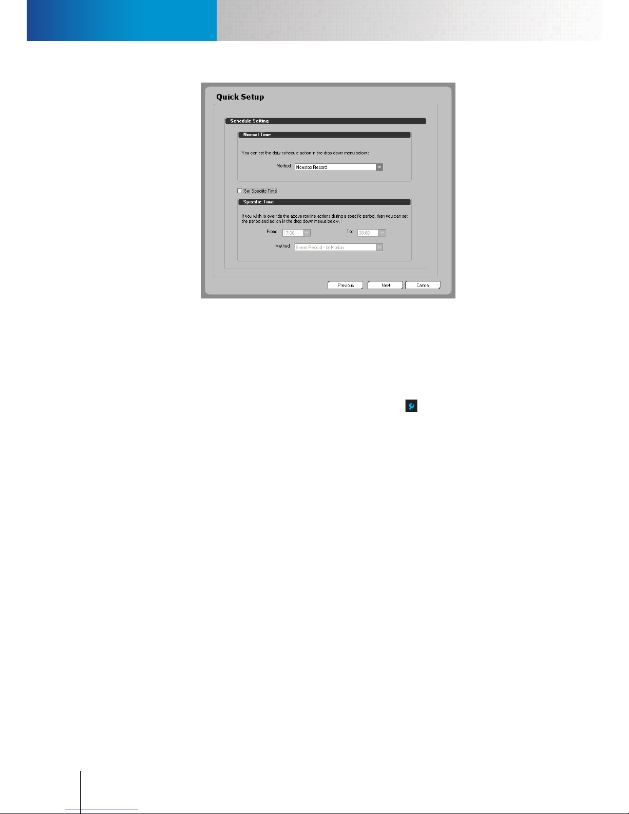
Set Up Event-Triggered Recording
Compro RS-3232 - User's Manual
7-2
Figure 7-2. Set up non-stop recording using Quick Setup
Set Up Event-Triggered Recording
As an alternative to Non-Stop recording, you can use event-driven recording to save disk storage space. For
instance, recording operation initiated by detected motion in the scene or detected audio. Follow the steps
below to set up the recording function.
1. Enter the system conguration console by clicking on the setup icon () and then choose “Setup” from
the y-out menu.
2. Go to the camera tab.
3. Click on the channel number (in the upper-left corner) for which you want to configure recording
operation.
4. Check “Enable” option in the Recording section. And select a recording method from the method dropdown list. In this case, choose "Event."
5. Set the amount of Pre-Recording time which determines the number of seconds to record BEFORE an
event is detected by the system. The event types include motion, audio, etc.
6. Set the amount of Post-Recording time which dictates the number of seconds to record AFTER a
detected event stops. The event types include motion, audio, etc. If after the system has started
recording for one event, and during the recording session, a second event is triggered, the postrecording will only begin when the event-recording for the last event stops.
7. In the Event-Recording field, fill in the number of seconds to record immediately AFTER an event is
triggered. Here it does not control the video recording length for a motion event. The system begins
recording when a motion event starts, and stops recording when this motion event stops. For events
other than motion, the total number of seconds to be recorded equals the amount of Pre-Recording
time, the amount of Event-Recording time, and the amount of Post-Recording time.
Each time a different motion/audio/IO event is triggered after the system has started recording one
event, the event recording timer is reset. In other words, if after the system has started recording for
one event, and during the recording session, a second event is triggered, then from the time point of
the second event’s occurence, the video recording length will be extended for the number of seconds
specied here.
Page 61
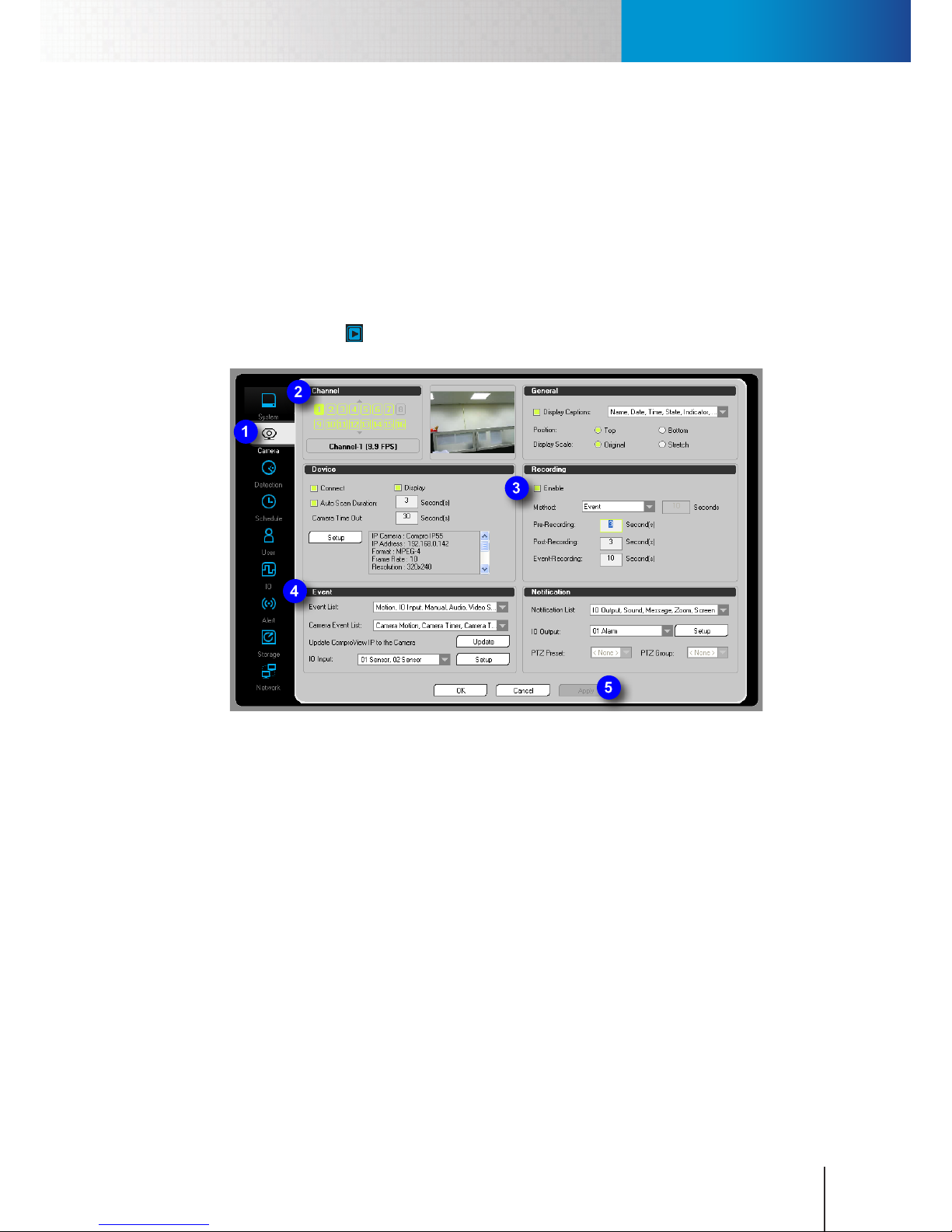
Set Up a Recording Schedule
Chapter 7: Recording
7-3
8. In the event section, click on the event list combobox (or camera event list combobox) and then pick
the event types you want to use to trigger event recording. The event list combobox contains all the
available event types that can be detected by ComproView®; the camera event list combobox consists
of all the available event types that can be detected by Compro IP cameras. In other words, use event
list combobox when you want to record events detected by ComproView®, or use camera event list
combobox to record events detected your Compro IP cameras (with the latter requires you to set up
Notify server on your Compro IP cameras).
9. Press “Apply” to save the changes.
10. Press “OK” to close the system conguration console.
11. Click the “Start all" icon (the icon shall then turn red) to start recording.
Figure 7-3. Set up event-based recording
Set Up a Recording Schedule
The “Schedule” tab of the system conguration console lets you tailor recording operations to your particular
applications. To schedule a recording operation, refer to following section.
Schedule Non-Stop Recording
To make ComproView® continuously record video during a specied time range:
1. Enter the system conguration console by clicking the Setup icon and then choose “Setup”.
2. Go to the “Schedule” tab.
3. Click on the channel number to choose a channel. The selected channel row will be highlighted in
light blue.
4. In the Time section, manually put in the start time and end time. Alternatively, you can click on the
timeline to set the start time, and then drag the time bar to the point in time when you want the
recording to end and then click again to set the end time. (You can use the horizontal scroll bar to
adjust the width of the timeline.) To update your start/end time, simply click and drag on the timeline
again.
Page 62
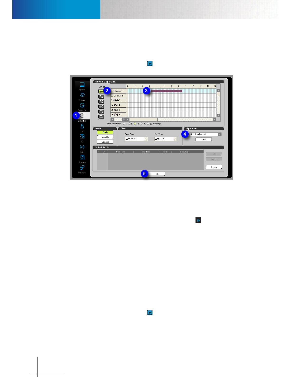
Set Up a Recording Schedule
Compro RS-3232 - User's Manual
7-4
5. Make sure “Non-stop Recording” is selected from the “Operation” drop-down list. Then, press “Add” to
add a new schedule.
6. Click [OK] to exit the conguration console.
7. In the system panel, click the “Start all" icon (the icon shall then turn red) to make your recording
schedule take eect.
Figure 7-4. Schedule non-stop recording
Schedule Event-Based Recording
You can make ComproView® record video only when a particular type of event is detected within a
specied time range:
1. Enter the system conguration console by clicking on the setup icon ( ) and then choose “Setup”
from the y-out menu.
2. Go to the "Schedule" tab.
3. Click on the channel number to choose a channel. The selected channel row will be highlighted in
light blue.
4. In the Time section, manually put in the start time and end time. Alternatively, you can click on the
timeline to set the start time, and then drag the time bar to the point in time when you want the
recording to end and then click again to set the end time. (You can use the horizontal scroll bar to
adjust the width of the timeline.) To update your start/end time, simply click and drag on the timeline
again.
5. Choose a method of event recording from the “Operation” drop-down list. Then, go ahead and press
“Add” to add a new schedule.
6. Click [OK] to exit the conguration console.
7. In the system panel, click the “Start all" icon (the icon shall then turn red) to make your recording
schedule take eect.
Page 63
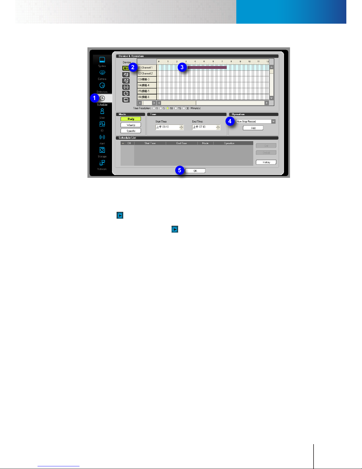
Enable/Disable Recording Schedules
Chapter 7: Recording
7-5
Figure 7-5. Schedule event-based recording
Enable/Disable Recording Schedules
The “Start all" button in the system utility panel lets you enable or disable scheduled operations, such as
recording, detection, backup, etc. To make your recording schedules and all the other scheduled operations
become effective, click the “Start all" icon ( ), which shall then turn red, to start all your scheduled
operations. To disable them, click on the icon again.
Alternatively, you can enable or disable all your recording schedules by clicking on the main button in the
system panel and then choose "Start/Stop Recording Schedule" from the y-out menu. This way you can start
only your scheduled recording operations and leave all the other scheduled operations unstarted.
Manual Recording
To manually start recording live video on a particular channel, simply right-click on the video pane of the
camera channel you wish to record, and then choose "Record" from the right-click menu. The red "REC"
text appear on the selected video pane, indicating video is being recorded on this channel. Once manual
recording is started, ComproView® will continue the recording as long as the disk space does not run out. To
stop the manual recording, simply right-click on the video pane again and choose "Stop" from the right-click
menu.
Page 64

Manual Recording
Compro RS-3232 - User's Manual
7-6
Page 65
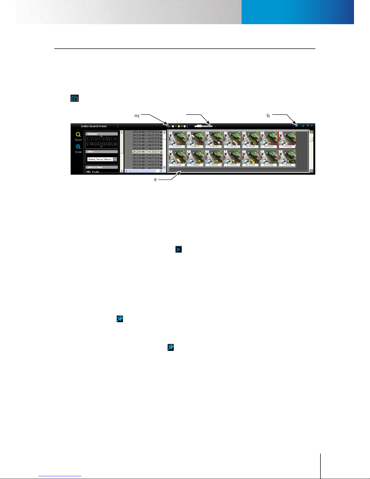
Index Search Panel
Chapter 8: Search & Playback
8-1
Chapter 8: Search & Playback
Index Search Panel
The Index Search Panel lets you search for recordings or snapshots that capture any past events. Using the
Index Search Panel, not only can you perform a search for event recordings and snapshots by channle, event
type, or time range, but you also can browse the thumbnails of the retrieved recordings and snapshots, which
helps you instantly locate the record of interest. To bring up the Index Search Panel, click on the Index icon (
) in the system panel. Then the following panel will be displayed.
Size radio
buttons
Lock/Unlock
Thumbnails
Size slider
Result pane
Figure 8-1. Index search panel
In this panel, you can specify your search criteria to search for a particular video clip. To do so:
1. First specify the channel number and event type in the "Channel" and "Filter" section.
2. If preferred, dene a time range to search by checking the "Enable" option in the "Date & Time" section
and then put in the start/end date/time.
3. Scroll down on the left and push the Go ( ) button. After that, the available recordings and snapshots
will appear in the result list as well as in thumbnails.
For any given thumbnail in this panel, a number in the upper-left corner indicates the channel on which this
recording is found; a green triangular indicates this item is a video clip, instead of an event snapshot, and can
be instantly played back with a double-click.
Lock/Unlock Thumbnails
You can choose whether to update the search results in real time based on current search criteria by using
the Lock/Unlock ( ) icon in the upper-right corner. Whenever ComproView® is monitoring and recording
videos while you are browsing the thumbnails, the new recordings and snapshots that match your current
search criteria will be updated into the result pane dynamically. Sometimes the new items can appear
in between the thumbnails you are inspecting and re-arrange the sequence of thumbnails. If this is not
preferred, you can click on the pin icon ( ) to lock the result pane, which will then be bordered in red, to
disable the real-time update.
Allow/Disallow Snapshots and Recordings
You can control whether snapshots and recordings can be created and queried in the Index Search Panel
when ComproView® detects an event on a particular camera channel.
To allow snapshots to be queried in the Index Search Panel, enter the system conguration console and
then go to the Camera tab. And choose a camera channel and check the "Display" checkbox in the Device
section. (This option controls whether to decode the video streamed from your camera; taking snapshots
requires ComproView® to decode the video rst.) To allow recordings to be queried in the Index Search
Page 66
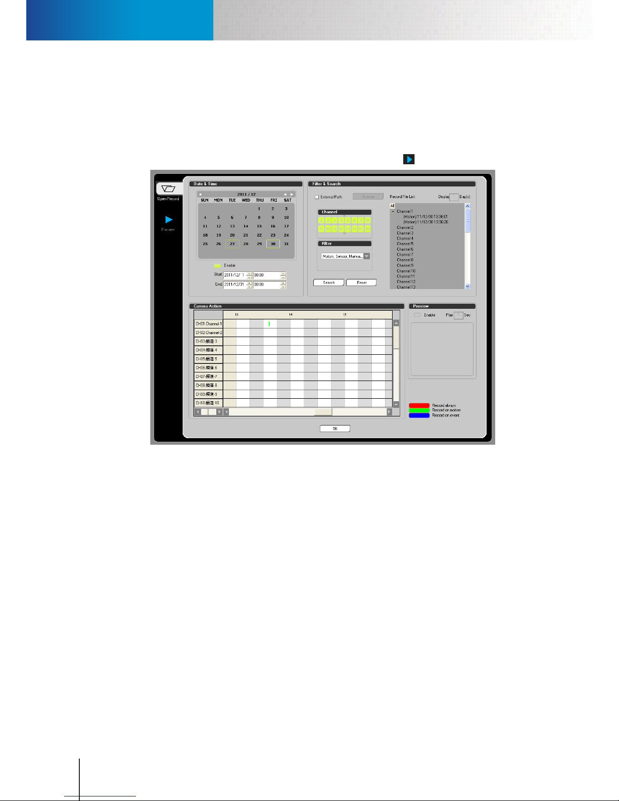
Playback Console
Compro RS-3232 - User's Manual
8-2
Panel, check the "Enable" checkbox in the Recording section.
Playback Console
The playback console allows you to search and play back all the videos recorded in the ComproView® system.
An intuitive and friendly search interface is here to help you quickly retrieve recordings of critical events from
the video database. To access the playback console, click the playback icon ( ) in the system panel.
Figure 8-2. Playback console
Set Search Criteria
You can search your recordings by date/time, event/event filter, or simply look for recordings created
within the past 1 to 3 days. By default, when you bring up the Playback console, all the channels and event
filters are selected and Date/Time is not enabled and taken into the search criteria. You can simply hit
“Search” and the found recordings, if any, will appear in the Record File List. Then double-click on any item
on the list to start playing a recording.
Follow the steps below to set your own search criteria.
1. To specify a time range, in the "Date & Time" section, check the "Enable" option and pick a date on the
calendar or manually put in a start/end date.
2. To specify the channel numbers, in the Channel section, select or deselect a channel to search.
3. To further narrow down your search scope, lter the events by type by clicking on the combobox in
the Filter section and then check the types you want.
4. Hit the [Search] button.
If you only want to find all the recordings made in the past few days on all of the channels, hit [Reset]
and then enter a value (between 1 to 7) into the "Display ( ) Days" field. And then press Enter key. The
Page 67
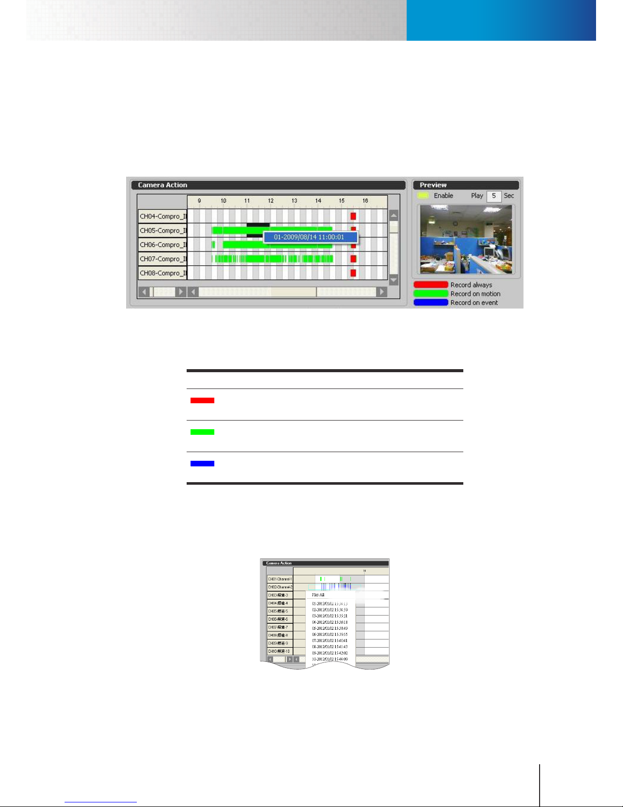
Playback Console
Chapter 8: Search & Playback
8-3
recordings made in the past few days, if there are any, will turn up in the list.
Camera Action
Camera Action shows you the timelines of events and recordings for all channels on a particular day on the
calendar. The Camera Action can provide a graphical representation as to what types of event recordings
were made on every channel and the start/end time of those recordings on a particualr day in the past. The
day can be chosen from the calendar or specied by choosing an item on the Record File List.
Figure 8-3. Camera action
The color bars used on the timeline mark when events had happened in the past. The following table
shows the event markers used in ComproView® and their meaning.
Color Meaning
The red bar represents a section in the timeline where video
recorded in non-stop mode or manual mode is available
The green bar represents a section in the timeline where video
recording triggered by motion detection is available.
The blue bar represents a section in the timeline where video
recording triggered by events other than motion is available.
Table 8-1. Meaning of color bar
You can click and drag on a section of the timeline where a color bar is present. A menu will then appear.
From the menu, you can choose to play back all event recordings made in the specied time range within
the timeline, or pick a particular video clip to play back.
Click and Drag
Figure 8-4. Click and drag on timeline
Page 68
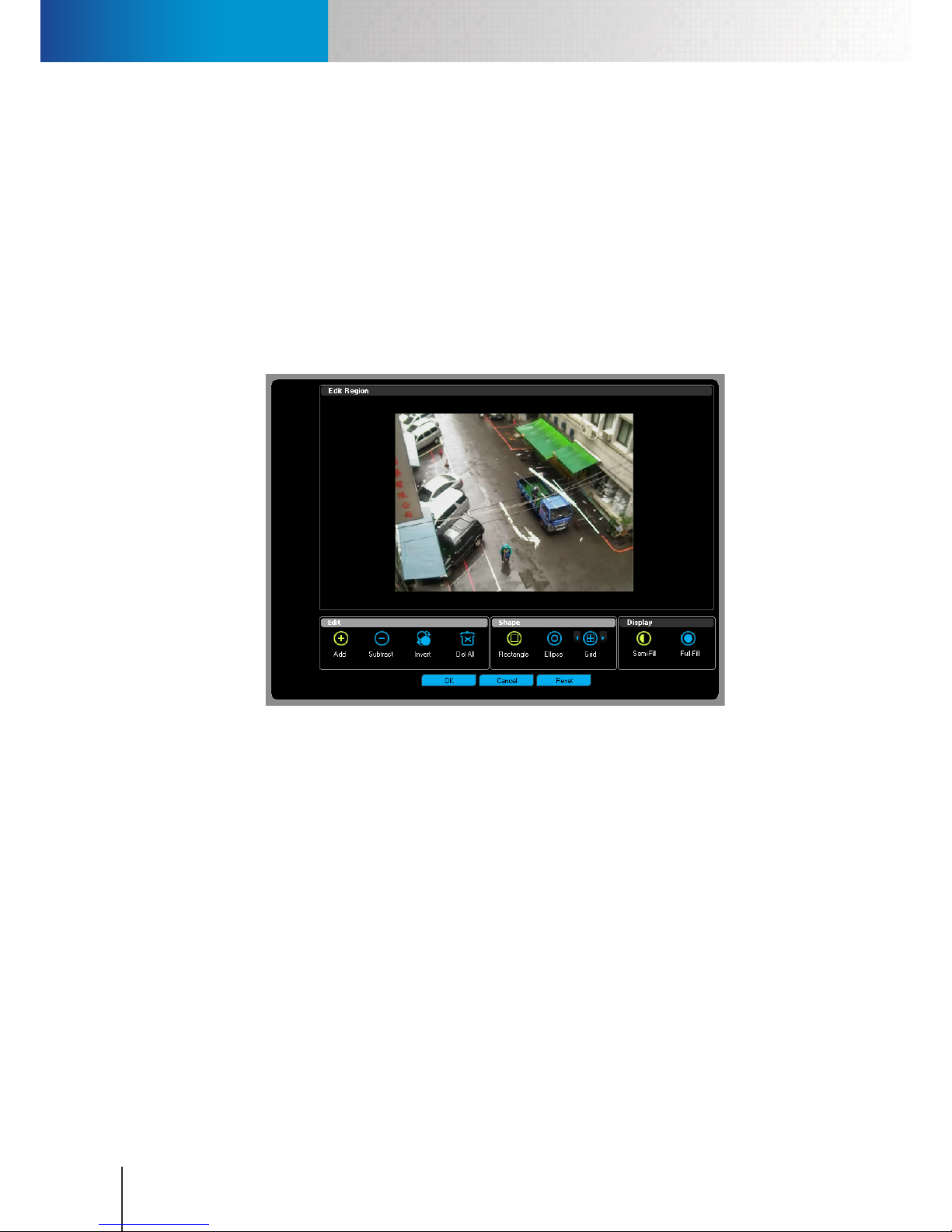
Using Smart Search
Compro RS-3232 - User's Manual
8-4
Using Smart Search
The smart search function allows you to search a video clip for particular events, such as motion, tampering,
intrusion, or tripwire, by intelligently analyzing the content of video. To use the Smart Search function, follow
the steps below.
1. Open the Playback console, set your search criteria, and hit [Search]
2. Double-click on any item on the Record File List to switch to the Preview tab.
3. Click Smart Search button in the Tools pane. A Smart Search window then appears.
4. Click on the Search Type combobox in the Search Type section, and choose an event type to search for.
5. If desired, press [Edit Region] to specify an area in the camera's eld of view to search. Hit OK when you
are done editing region.
Figure 8-5. Editing region
6. Press [Search] to start analyzing and searching the video recording for a particular type of event. If
ComproView® detects this particular event in the video, it will list the video frame that captured the
event in the result pane. You can then double-click on any item in the Search Result pane to jump to the
very frame in the video recording where this particular type of event is captured. You can also select one
item in the Search Result pane and press [Bookmark] to create a bookmark for this specic frame.
Page 69
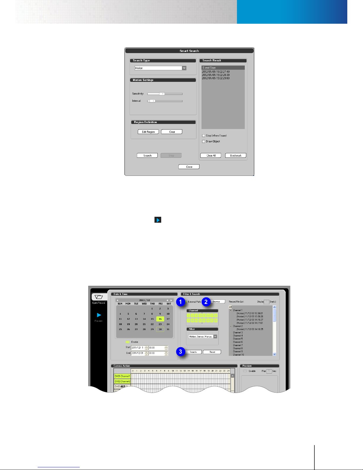
Play Back from Backup
Chapter 8: Search & Playback
8-5
Figure 8-6. Smart search window
Play Back from Backup
You can also play back videos from your ComproView® database backup le. To do so, bring up the playback
console by clicking the playback icon ( ) in the system panel. Then refer to the following steps.
1. Check the "External Path" checkbox and hit the "Browse" button.
2. A "Browse For Folder" window pops up. Select a folder destination that contains ComproView® database
backup le. Then click [OK].
3. Set you search criteria and specify the time range, channel numbers and event types.
4. Hit the [Search] button.
5. Double-click on any item that appears in the "Record File List" to play back.
Figure 8-7. Play back from backup
Page 70
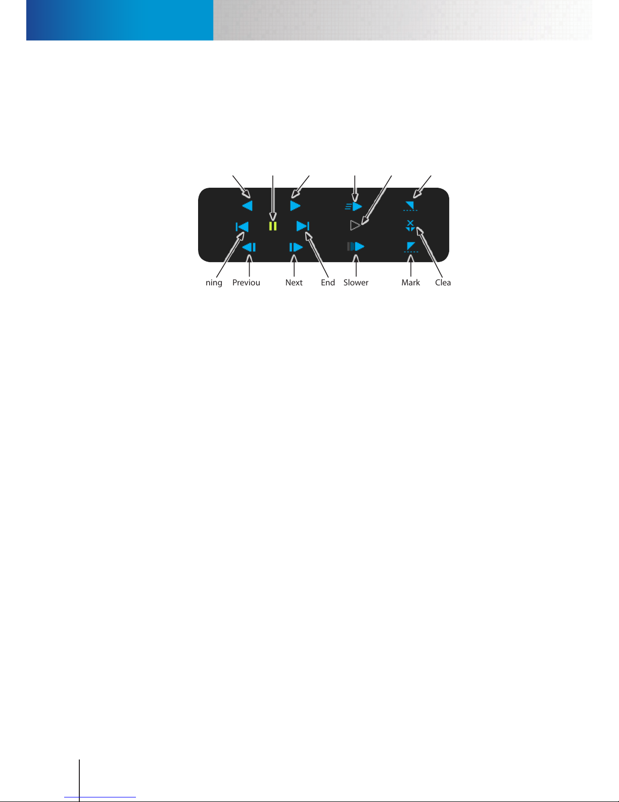
Playback Control
Compro RS-3232 - User's Manual
8-6
Playback Control
Double-click on an item on the Record File List and you will be directed to the Playback tab in the Playback
console with the following Playback control buttons. Playback control buttons let you change playback
speed, fast forward, rewind, etc. Playback control buttons are explained as follows.
Next
Frame
Slower Mark
End
Clear
Markers
Previous
Frame
Beginning End
Rewind
Normal
Speed
Mark
Start
Pause FasterPlay
Figure 8-8. Playback control
• Rewind – Switch to reverse playback mode. Reverse playback speed can be changed with the "Faster" and
"Slower" button.
• Pause – Click this button to stop playback. Click "Play" to resume playback.
• Play – Click "Play" to start playback. Playback speed can be changed with the "Faster" and "Slower" button.
• Beginning – Jump to the beginning of the video.
• Previous Frame – Click to move the video backward one frame.
• Next Frame – Click to move the video forward one frame.
• End – Jump to the end of the video.
• Faster – Switch to fast forward mode. Click twice or more to speed up playback further.
• Normal Speed – Return to normal playback speed.
• Slower – Switch to slow motion mode. Click twice or more to slow down playback further.
• Mark Start – Used to mark the current position of the seek bar as the beginning of a time range for export-
ing video.
• Clear Markers –Clear all markers.
• Mark End – Used to mark the current position of the seek bar as the end of a time range for exporting
video.
Synchronous Multi-Channel Playback
You can simultaneously play back up to 4 channels of recordings (which are synchronized in time). To do so:
1. Enter the Playback Console first and then perform a search. After that, click on two or more grayish
columns (row header) in the Camera Action section that contains channel number and camera name.
The channels to be played simultaneously (up to 4) will be highlighted in yellow.
2. Then double-click on any item in the "Record File List" in the upper-right corner (or click and drag on a
Page 71
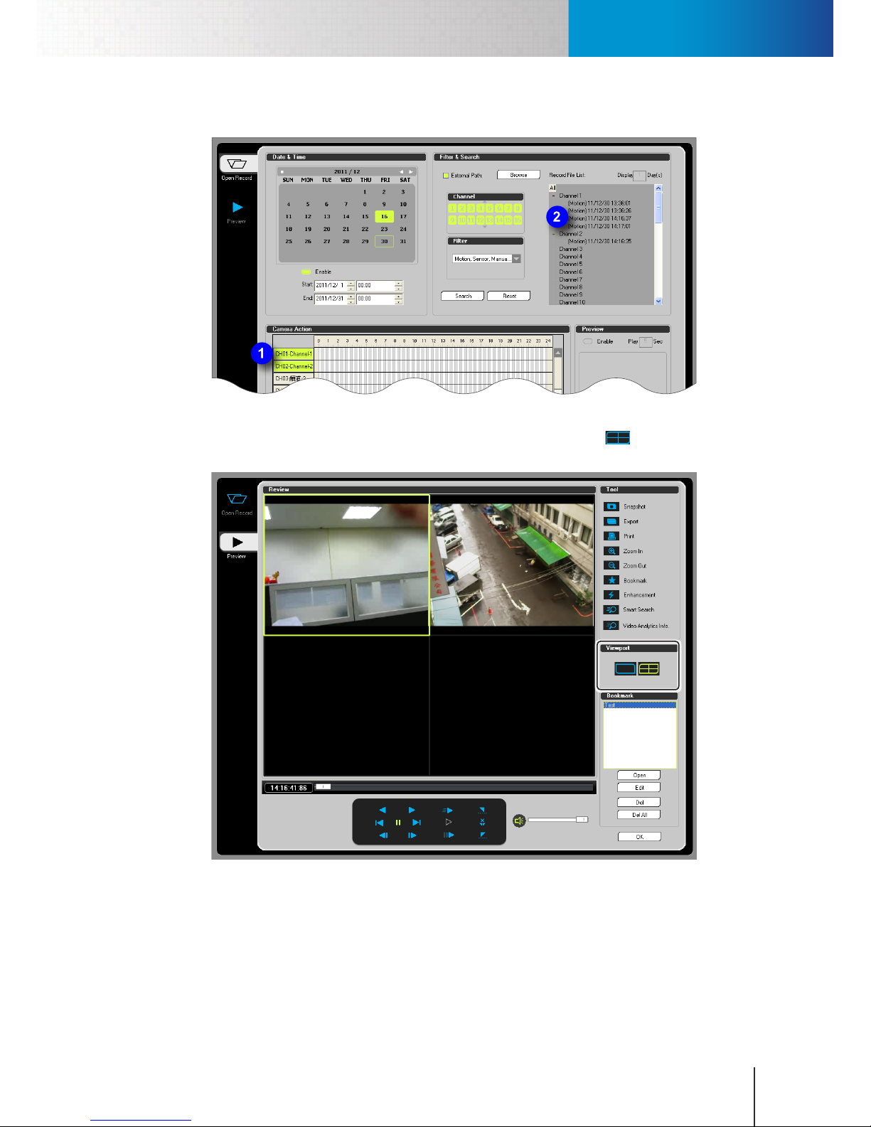
Synchronous Multi-Channel Playback
Chapter 8: Search & Playback
8-7
section of the timeline where events have been marked with colored bars) to go to the Preview tab.
Figure 8-9. Highlight multiple channels
3. Once you are re-directed to the Preview tab, click the 2 x 2 layout button (
) to switch to multi-
channel playback mode.
Figure 8-10. Synchronous playback
During synchronous multi-channel playback, the start time of the recording you have chosen from the
"Record File List" will be the time used to synchronize the start time of all 4 channels. In other words, the
video on all 4 channels will be synchronized based on the start time of the recording you previously doubledclicked on. In addition, in multi-channel mode, you can only continuously play back up to 1 hour of video.
Page 72
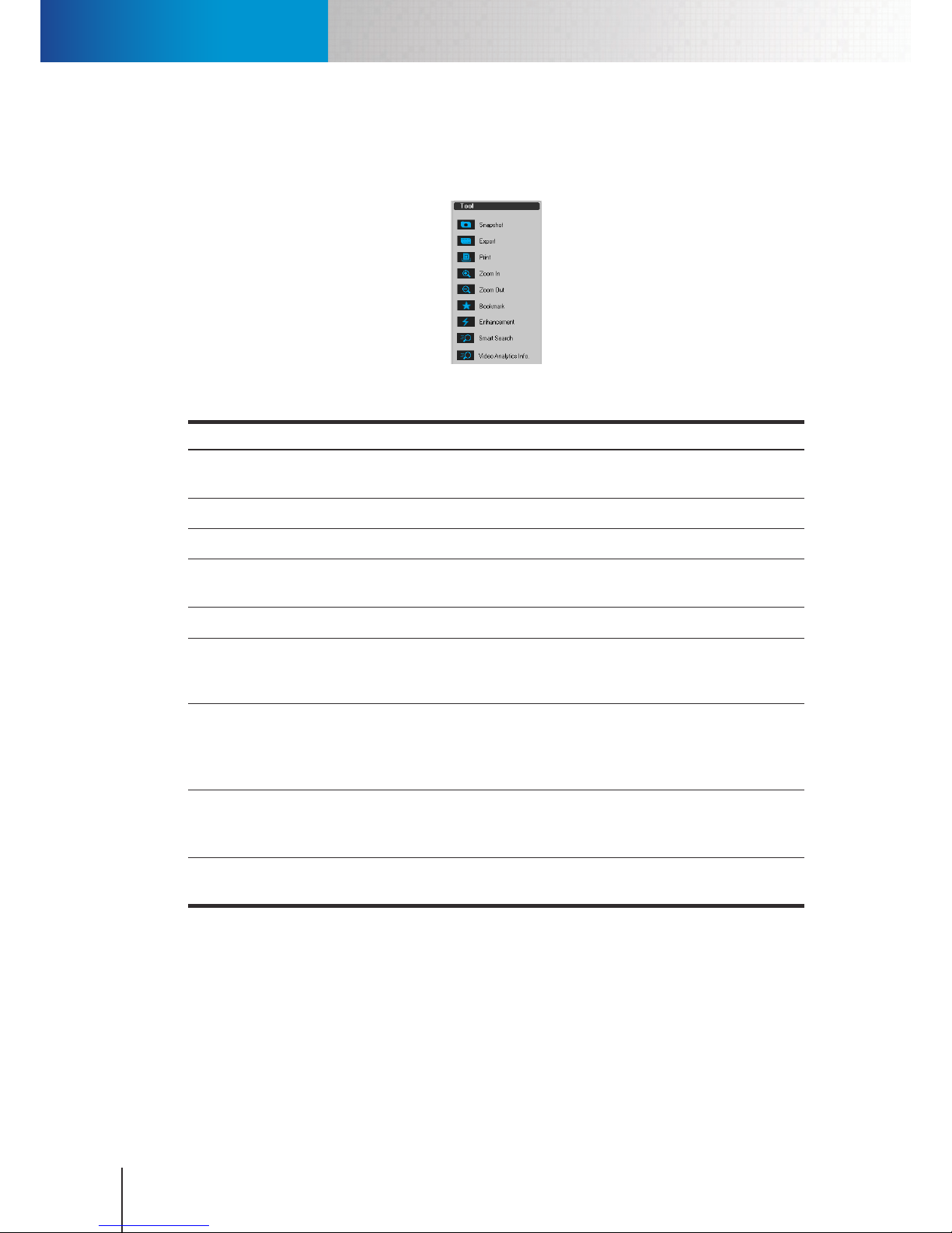
Playback Tools
Compro RS-3232 - User's Manual
8-8
Playback Tools
While you are playing back video recordings, you can perform other operations using the tools in the Tools
pane of the playback console. The tools are explained below.
Figure 8-11. Playback tools
Item Description
Snapshot Take a snapshot of the current video frame and save it as a BMP image le in the specied
location.
Export Export the video clip to an external destination in WMV format.
Print Print out current playback frame (picture).
Zoom In Enlarge the playback image. You can also click and hold on any spot of the enlarged playback
image and move your cursor to digitally pan/tilt the image within the video pane.
Zoom Out Zoom out on the enlarged playback image.
Bookmark Create a bookmark on current playback position for quick access to a specific playback
position later on. After a bookmark is saved, double-click the bookmark on the list to start
playing back from the bookmarked position.
Enhancement
Bring up a Video Enhancement panel that allows you to adjust brightness, contrast, hue,
saturation, visibility, and sharpness. To apply enhancement, check the "Enable" option,
and then use the slider to adjust video quality to your preference. After that, click [OK] to
save changes.
Smart Search
Select a video pane and click the button to bring
up a Smart Search panel that allows you
to comb through the recording and search for moments in the video when motion,
tampering, intrusion, or tripwire events occur. See "Using Smart Search" for details.
Video
Analytics Info
Select a video pane and click the button to bring up a "VAE information" window that allows
you to toggle the display of video analytics markers in the video.
Table 8-2. Available playback tools
Add and Manage Bookmarks
Bookmarks allow you to mark the position of a specic video frame in a video recording and to later on play
back a video recording starting from a bookmarked position. In ComproView®, after a bookmark is saved, you
can double-click the bookmark on the list to start playing back from the bookmarked position.
Page 73
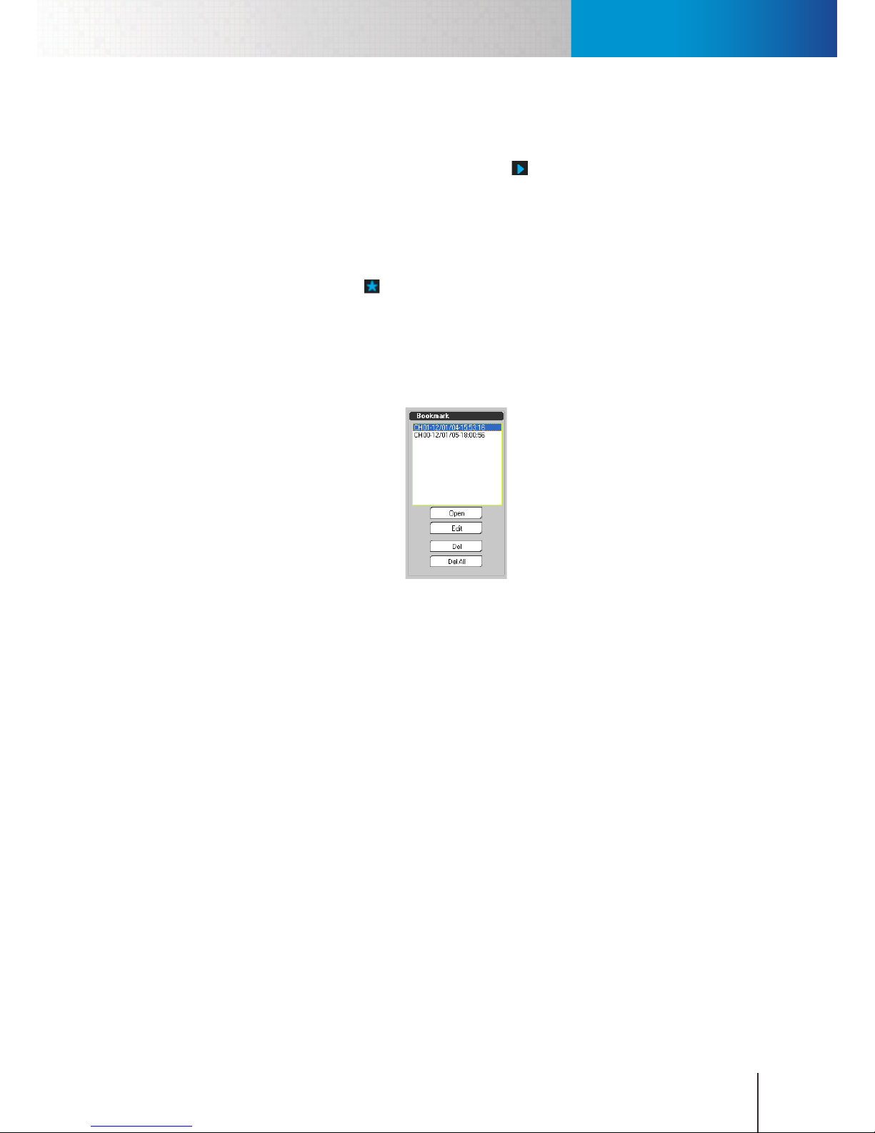
Add and Manage Bookmarks
Chapter 8: Search & Playback
8-9
Add a Bookmark
To add a bookmark, you need to:
1. Enter the playback console by clicking the playback icon ( ) in the system panel.
2. Set you search criteria and specify the time range, channel numbers and event types. Then hit the
[Search] button.
3. Double-click on any item that appears in the "Record File List" to go to the Preview tab.
4. While the video is playing, drag the seek bar to the desired position and then click "Pause."
5. Click the "Bookmark" button ( ) in the Tools pane. Up comes a "Bookmark Editing" dialog box.
6. Enter the name of the Bookmark and then click [OK].
7. After a bookmark is saved successfully, you can simply open the Playback console again and go to
the Preview tab. Then choose a bookmark from the Bookmark pane and click "Open" (or double-click
on the bookmark) to start playing back a video recording from the bookmarked position you have
selected.
Figure 8-12. Bookmark pane
Rename and Remove Bookmarks
To rename a bookmark:
1. Go to the Preview tab of the Playback console.
2. Choose a bookmark from the Bookmark pane and click on the "Edit" button.
3. Up comes a "Bookmark Editing" dialog box. Go ahead and enter a dierent name for the Bookmark.
Then click [OK].
To remove a bookmark:
1. Go to the Preview tab of the Playback console rst.
2. Choose a bookmark from the Bookmark pane.
3. Then click on the [Del] button to delete the selected bookmark. To delete all of the saved bookmarks
in ComproView®, click [Del All] instead. And then click [OK] to conrm the operation.
Page 74

Add and Manage Bookmarks
Compro RS-3232 - User's Manual
8-10
Page 75
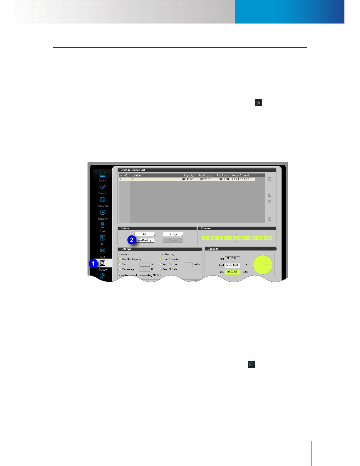
Pre-Backup Setting
Chapter 9: Backup
9-1
Chapter 9: Backup
Pre-Backup Setting
Add a Backup Directory
You can manually back up ComproView® database or arrange ComproView® to perform daily or weekly
routine backup automatically. But in order to arrange an automatic backup operation, you need to add a
backup directory to ComproView® system beforehand. To do so:
1. Click on the “Setup” icon located in the system panel (represented by a wrench ). Then select “Setup”
from the y-out menu. And the system conguration console will come up.
2. Go to the “Storage” tab. After that, press [Add Backup] in the Option section.
3. A "Browse For Folder" window pops up. Select a folder destination that will be used to store
ComproView® video archives. Then click [OK].
4. Click [OK] again to exit the system conguration console. After that, this folder destination will be the
default backup destination when you attempt to schedule a backup operation.
Figure 9-1. Add backup directory
Add a Backup Schedule Setting (For Scheduled Backup)
If you plan to schedule a backup operation in ComproView®, besides dening a system backup directory
in advance, you also need to rst create a backup schedule setting using the backup console. And after
that go to the Schedule tab in the system conguration console and schedule a backup time. So when the
scheduled backup time arrives, ComproView® runs the backup in accordance with your backup setting.
In the backup console, you may add more than one backup schedule setting. At the appointed time,
ComproView® runs all backup schedule settings.
To add a backup schedule setting, rst bring up the backup console (by clicking ) and then:
1. Press the [Schedule] button in the Settings section.
2. Enter a number in the "Day(s)" field to determine how many days of data generated prior to the
appointed backup time will be backed up by ComproView®. Then, set the backup time range for each
day in the past.
3. Enter a name for the schedule setting.
Page 76
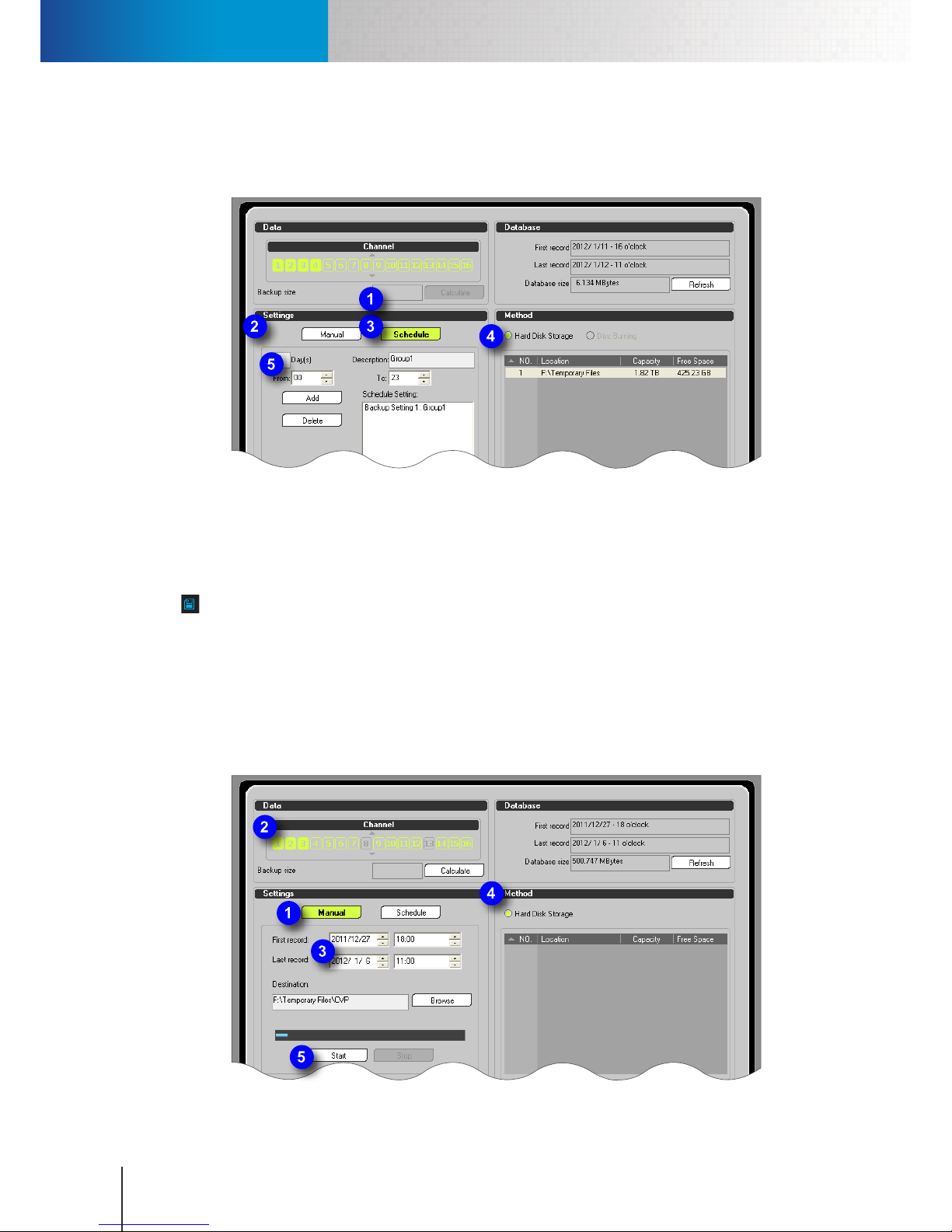
Manual Backup
Compro RS-3232 - User's Manual
9-2
4. Choose a backup method ("Hard Disk Storage" as in this case) and then select a location from the list
in the method section.
5. Hit [Add] to complete the operation.
Figure 9-2. Add a backup schedule setting
Manual Backup
To manually back up ComproView® database to an external disk, attach the external disk to the RS-3232 rst
and then bring up the Backup console by clicking on the backup button (represented by a oppy disk icon
) in the utility panel. Then refer to the following steps.
1. Press the [Manual] button in the Settings section.
2. Choose the camera channels to back up by clicking on the channel numbers in the upper-left corner.
3. Put in the date and time of the rst record and the last record to delimit the time range for backup.
4. In the Method section, choose the backup method "Hard Disk Storage"." After "Hard Disk Storage" is
selected, hit the [Browse] button and go on to select a folder destination.
5. Finally, push [Start] to begin backup and wait patiently for the backup to complete.
Figure 9-3. Manual backup
Page 77
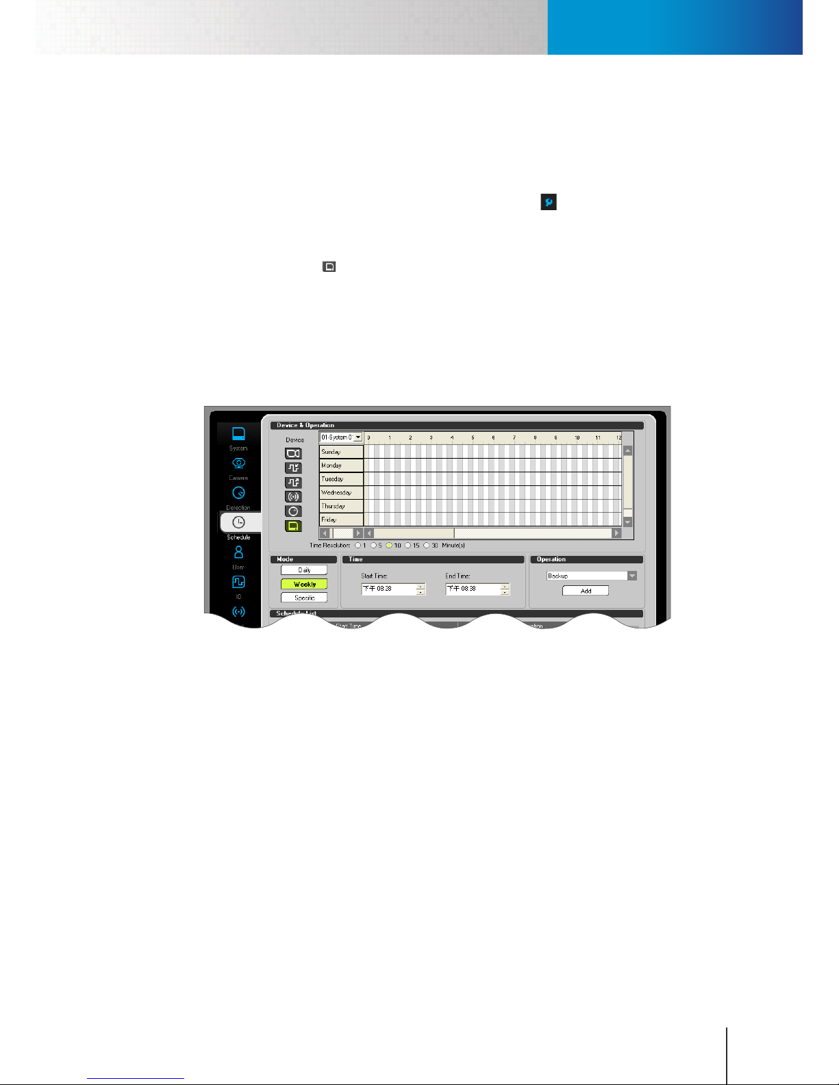
Schedule a Backup Operation
Chapter 9: Backup
9-3
Schedule a Backup Operation
You can schedule ComproView® to perform backup on a daily or weekly basis or on a specic calendar day. To
do so, add a backup schedule setting in the backup console rst, and then follow the steps below to schedule
a backup time.
1. Enter the system conguration console by clicking on the setup icon () and then choose “Setup” from
the y-out menu.
2. Go to the “Schedule” tab.
3. Click on the monitor icon ( ) in the Device & Operation section.
4. Choose a backup method in the Method section (between Daily, Weekly, and Specic). When [Weekly]
is selected, you must click on one row header in the timeline to pick a day in the week; when [Specic] is
selected, you must pick a day from the calendar.
5. Punch in the Start Time in the Time section. This will be the time at which the scheduled backup will be
started.
6. In the Operation section, click on the combobox and choose "Backup" as the operation.
Figure 9-4. Schedule a backup operation
7. Hit [Add] to add this backup operation to ComproView® schedule.
8. Click [OK] to exit the system conguration console. Then click on the “Start/Stop All” icon in the system
panel to complete the setup.
Page 78

Schedule a Backup Operation
Compro RS-3232 - User's Manual
9-4
Page 79
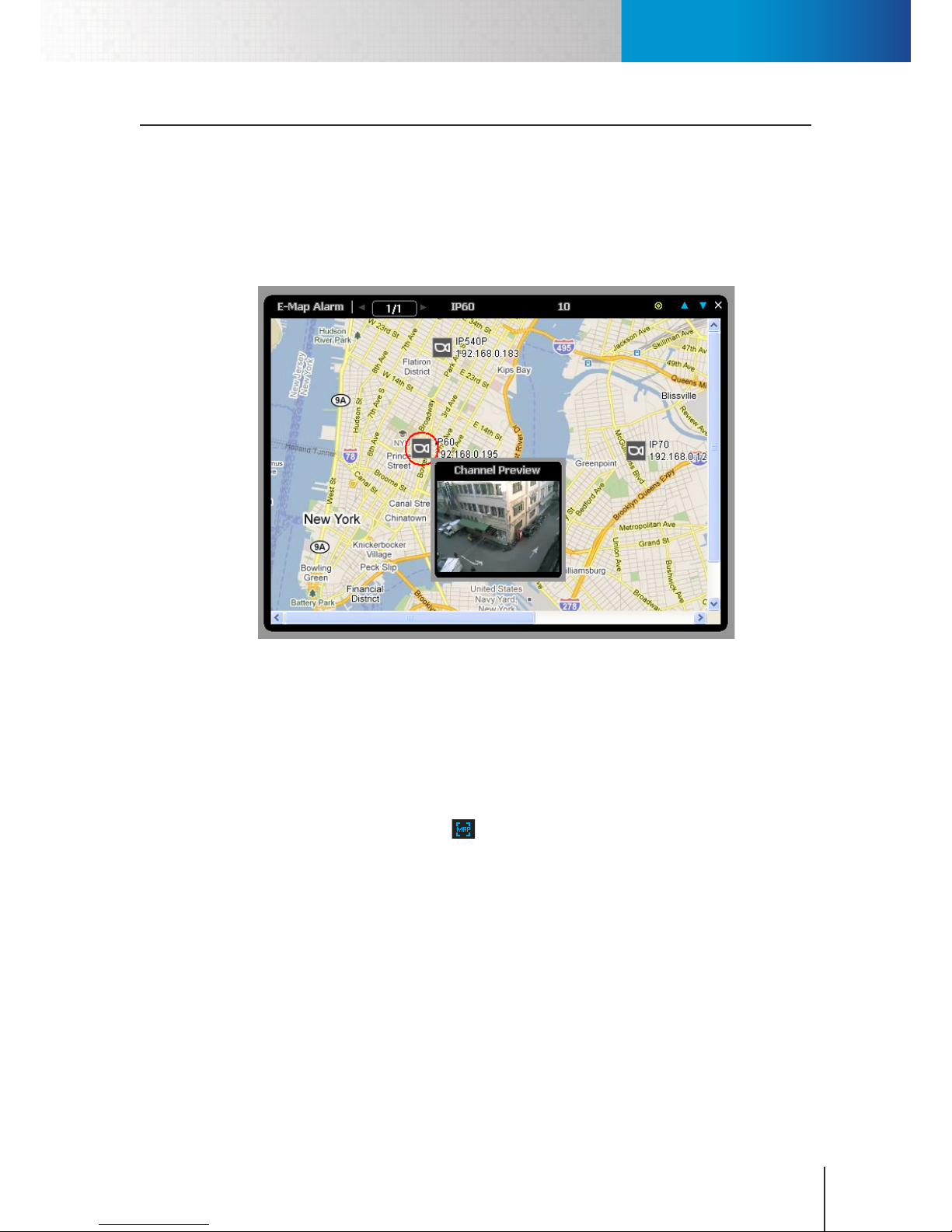
E-Map
Chapter 10: E-Map
10-1
Chapter 10: E-Map
E-Map
E-Map provides security sta a visual overview of the surveillance system. Using the E-Map function, you can
congure the system to pop up a graphical oor plan on which a specic camera's location is marked and
live video of the monitored site is shown when an event like a break-in (motion/IO event) happens at the
monitored site. So operators can quickly nd out the exact location of the triggering event and determine
how to respond to the situation directly. The following gure is a demonstration of an E-Map alarm window
that pops up when events are triggered.
Figure 10-1. Emap alarm
In ComproView®, E-Maps are set up using the E-Map Editor. Before you use the E-Map function, you need to
click the map icon in the utility panel to set up the E-Map function. Then in the E-Map Editor, add an image of
a map or oor plan to the system and then drag your cameras to the map to mark their locations.
E-Map Editor
The E-Map Editor allows you to load maps into ComproView® and manage device locations on the map. To
enter the E-Map Editor, click on the map icon ( ) in the utility panel of ComproView®, and then the E-Map
Editor will be displayed. To close the E-Map Editor, click the "X" icon in the upper-right hand side. To enlarge
or shrink the E-Map Editor window, click the up arrow or down arrow icon. The following section explains the
layout of the E-Map Editor.
Page 80
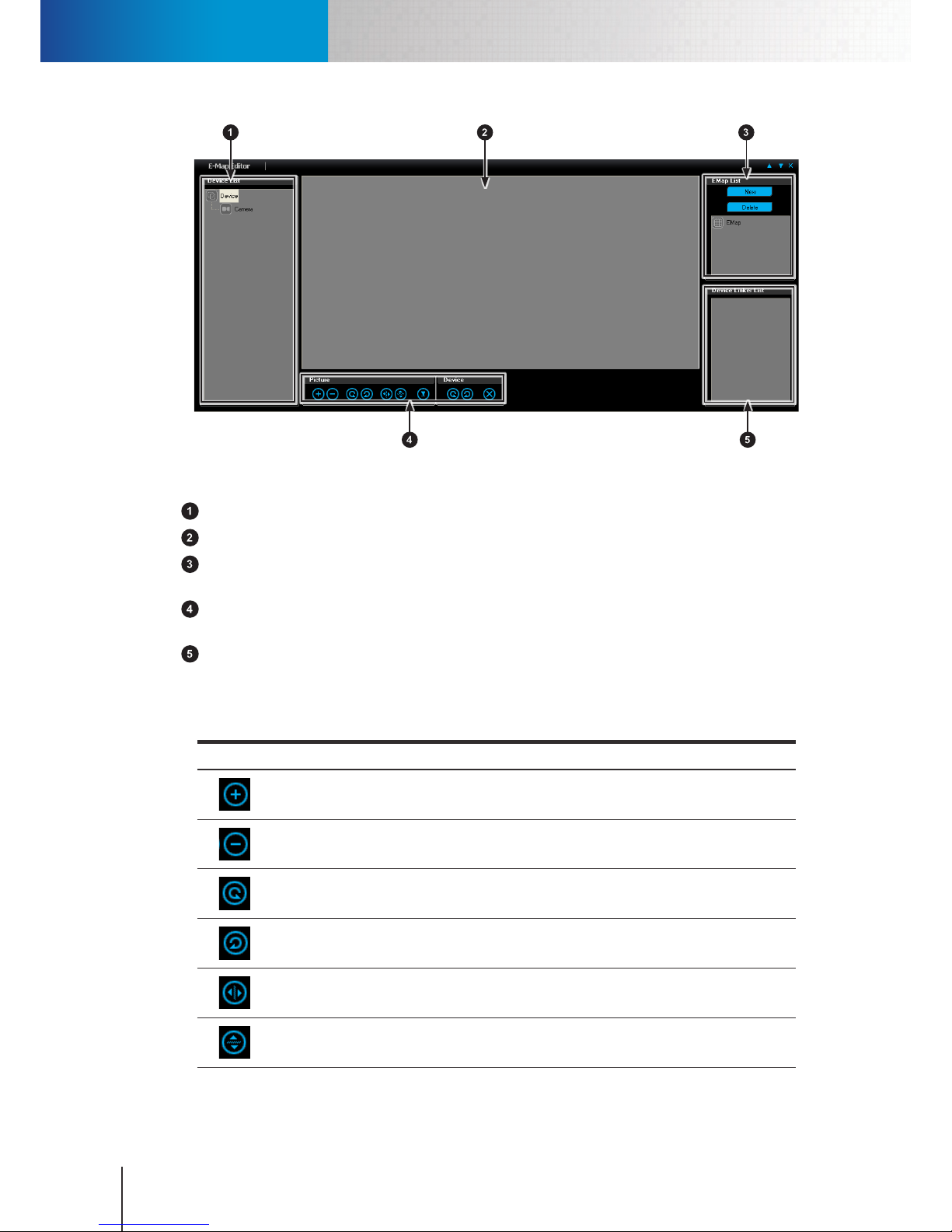
E-Map Editor
Compro RS-3232 - User's Manual
10-2
Figure 10-2. E-Map editor
Device list – Displays a list of devices that have been connected to ComproView®.
Map pane – Displays the map image you selected from the E-Map list.
E-Map list– Allows you to add or remove a map and toggle between dierent maps. Click [New] to load a
new map image into E-Map Editor. To remove an map, choose one from the list and hit [Delete].
Transformation tools – Lets you transform the map and rotate the device on the map, including cameras
and other I/O devices (sensors and alarms).
Device linker list – Displays a list of devices that have been placed on the map.
Transformation Tools
The followings are the picture transformation tools available in the E-Map Editor.
Icon Name Description
Scale Up Click to zoom in on the map.
Scale
Down
Click to zoom out of the map.
Rotate Left
Rotate the map 90 degrees counterclockwise.
Rotate
Right
Rotate the map 90 degrees clockwise.
Flip Horizontal
Flip the map image horizontally.
Flip Vertical
Flip the map image vertically.
Page 81
Add an E-Map
Chapter 10: E-Map
10-3
Icon Name Description
Reset
Picture
Restore the map to its original state.
Table 10-1. Transformation tools
The followings explain the device transformation tools available in the E-Map Editor.
Icon Name Description
Rotate Left
Rotate the selected device on the map 15 degrees counterclockwise.
Rotate
Right
Rotate the selected device on the map 15 degrees clockwise.
Delete
Remove the selected device from the map.
Table 10-2. Transformation tools (continued)
Add an E-Map
Refer to the following steps to add a new E-Map to ComproView®.
1. Click on the map icon ( ) in the utility panel of ComproView®, and then the E-Map Editor will be
displayed.
2. In the upper-right hand side of the E-Map Editor, hit [New] to add a new map.
3. Up comes an "Open File" window. Choose a map image le and click [Open].
4. If desired, zoom into or rotate the map by selecting the map from the E-Map list rst and then click on a
picture transformation button.
5. Then drag a camera from the device list and drop it onto the map to mark its location on the map.
6. You can select a device icon on the map and use the device tools to rotate the device icon clockwise or
counter-clockwise, or click [Delete] to remove the device icon from the E-Map.
After you have placed some cameras or devices on the E-Map, you can double-click on a device on the list to
quickly locate your device on the map. Additionally, clicking a device icon on the map will pull up a live video
window of that device.
Page 82
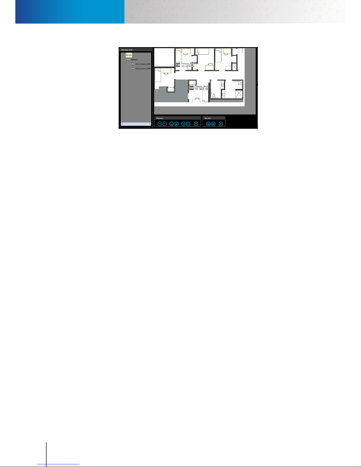
Add an E-Map
Compro RS-3232 - User's Manual
10-4
Figure 10-3. Emap example
Page 83
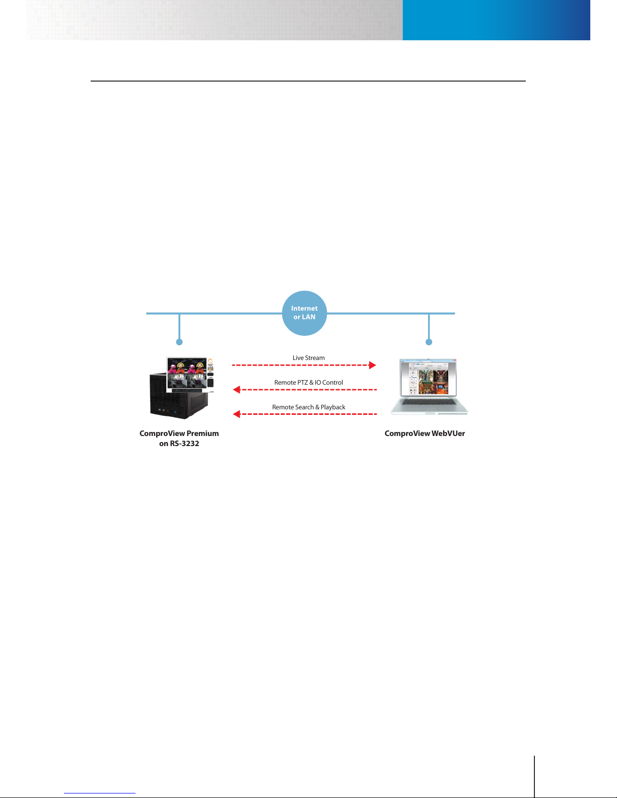
ComproView® WebVUer
Chapter 11: Remote Access
11-1
Chapter 11: Remote Access
If you like to access your RS-3232 remotely from the Internet, ensure that you have set up a router that connects to
your RS-3232 in your LAN network. A router's job is to connect your LAN network where RS-3232 is located on to the
public network (Internet). After that, set up the port forwarding (also known as port mapping or virtual server on
certain brands of routers) function on your router.
To set up port forwarding for remote access, log in to your router's web interface first, and then, one after one,
manually map the router's public ports to the private ports and IP address the RS-3232 will be using on the LAN
network. Only after you have properly set up port forwarding can you connect to your RS-3232 in your LAN network
from a public network. Refer to the "Typical Network Conguration" section for a setup example on port forwarding.
ComproView® WebVUer
ComproView® WebVUer is a remote web client for accessing the RS-3232 remotely either from another PC
that connects to the same LAN network as RS-3232, or from a remote PC on the Internet. Using ComproView®
WebVUer, you can monitor live video being displayed on the RS-3232, and search and play back video
recordings stored on the RS-3232 remotely.
ComproView Premium
on RS-3232
ComproView WebVUer
Live Stream
Remote PTZ & IO Control
Remote Search & Playback
Internet
or LAN
Figure 11-1. Function of remote access
WebVUer also supports multiple RS-3232 servers, so you can view camera channels on different RS-3232
servers in the same browser window using WebVUer. For instance, on the Live View page of WebVUer, you can
have the rst 10 channels displaying live video streams from server 1 and the second 10 channels displaying
live video streams from server 2, and so on.
Moreover, ComproView® Premium supports multiple clients, which means dierent operators and users can
all use WebVUer to access the same RS-3232 server running ComproView® Premium at the same time. Refer
to the following gure.
Page 84
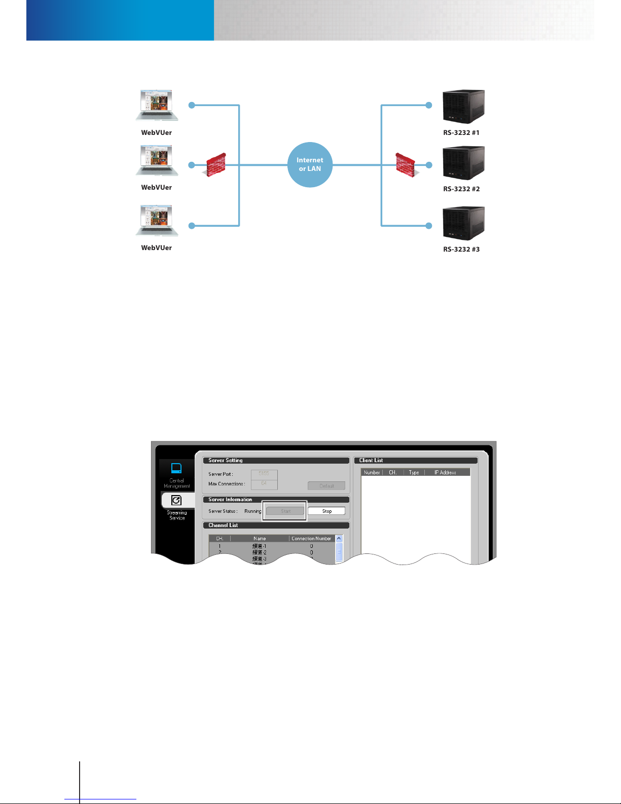
Log Into RS-3232 on WebVUer
Compro RS-3232 - User's Manual
11-2
Internet
or LAN
RS-3232 #1
RS-3232 #2
RS-3232 #3
WebVUer
WebVUer
WebVUer
Figure 11-2. Network architecture
Log Into RS-3232 on WebVUer
You can log in to RS-3232 using ComproView® WebVUer, which is a platform on Internet Explorer with
intuitive browser interface and allows you to monitor the camera channels on the RS-3232 remotely. But
beforehand, you need to make sure you have enabled the remote streaming service and HTTP server in
ComproView®.
To enable the streaming service:
1. Click on the “Setup” button located in the system panel and choose "Remote Setup" from the fly-out
menu. Then the remote setup console is displayed.
2. Go to the "Streaming Service" tab.
Figure 11-3. Enable streaming service
3. Click on the [Start] button in the Server Information section. When the streaming service is not enabled,
ComproView® will not be able to stream video to the remote PC.
4. Click [OK] to nish setup.
To enable the streaming service:
1. Click on the “Setup” button located in the system panel and then choose “Setup” from the y-out menu.
2. Switch to the Network tab and now make sure the HTTP server is started.
Page 85
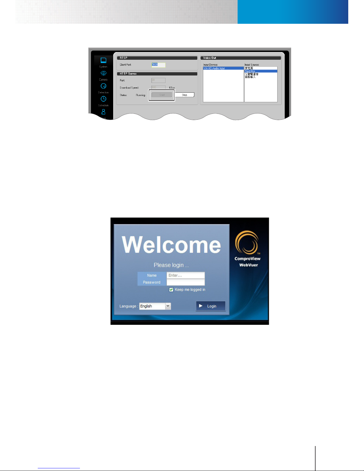
Log Into RS-3232 on WebVUer
Chapter 11: Remote Access
11-3
Figure 11-4. Enable HTTP server
After that, follow the steps below to access the RS-3232 remotely on web browser.
1. Open the Internet Explorer on your Windows PC and enter the RS-3232’s IP address, either public or
private one, into the address eld. (You must set up port forwarding on your router that connects to
your RS-3232 in order to enable remote access from the Internet to your RS-3232 on your LAN network.)
2. A dialog box that requests the user name and password appears. Meanwhile, depending on local
settings, the browser may prompt a security bar saying “The website wants to install the following addon…” Click on the information bar and choose to install and run the add-on.
3. After that, enter a valid user name and password. Then click on “Log in.” The default user name and
password are both “admin.”
Figure 11-5. WebVUer login screen
4. At the very rst time you log in to ComproView® WebVUer, a "Channel Setting" window will come up
asking you to choose the channels you like to add to the WebVUer client. If you have set up camera
connections in ComproView®, you can then select the channels you want to monitor on the web
browser and then click [OK] to proceed.
Page 86
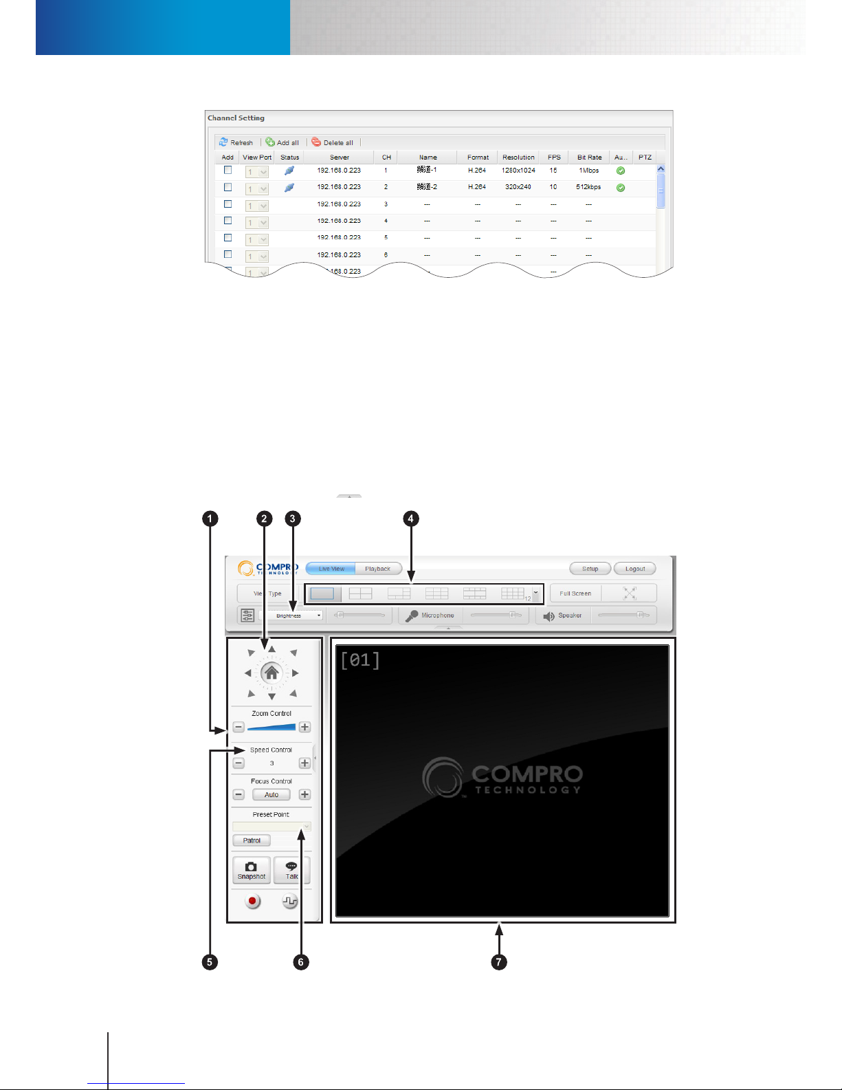
Remote Monitoring on WebVUer
Compro RS-3232 - User's Manual
11-4
Figure 11-6. Initial channel setting
5. Now you can start using ComproView® WebVUer on Internet Explorer to access your RS-3232.
Remote Monitoring on WebVUer
To remotely monitor camera channels on RS-3232, please enter the LAN (private) or WAN (public) IP address
of the RS-3232 into the address eld of Internet Explorer. The Live View page is the default page displayed
once you have successfully logged in to the RS-3232.
LiveView Page Layout
You can see the basic control panel at the top and on the left-hand side, and the live video pane on the
right-hand side. Clicking on the icon will allow you to hide or show the control panels.
Figure 11-7. LiveView page
Page 87
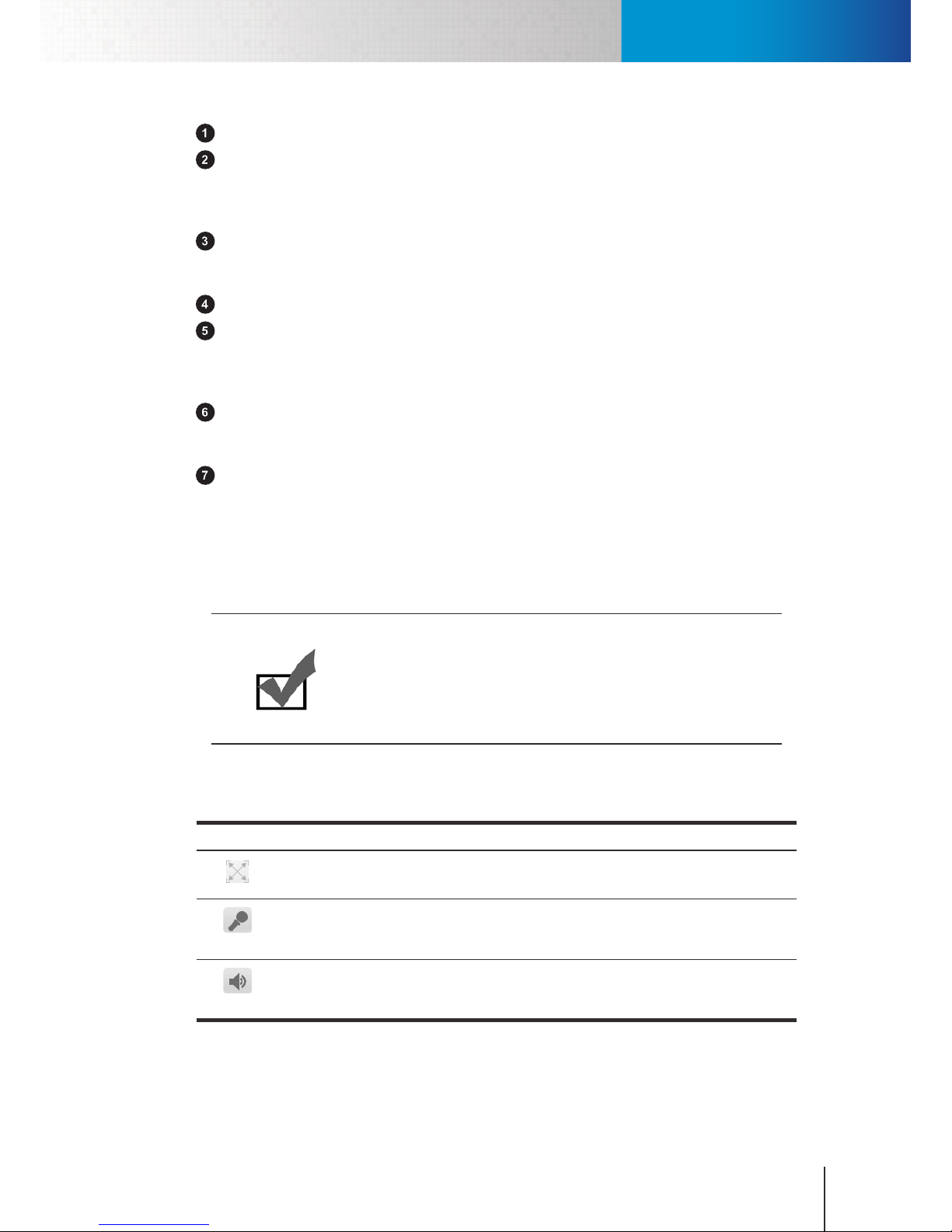
Remote Monitoring on WebVUer
Chapter 11: Remote Access
11-5
Left control panel – Click on the triangle icon to hide/ show the panel.
PTZ control – For controlling the Pan/ Tilt functionality of the selected PTZ camera. Select a PTZ camera
channel and click the triangles to move the camera view in the desired direction. Click the house icon
to return to the home position. The PTZ control buttons are dimmed when a non-PTZ camera channel
is selected. The same buttons are used to perform the digital PTZ operations.
Enhancement function – Allows you to adjust brightness, contrast, hue, saturation, visibility, and
sharpness. To apply enhancement, click "Enhancement" and select an item, and then use the slider to
adjust video quality to your preference.
View type buttons – Lets you change video screen layout.
Zoom/Speed/Focus control – Allows you to change zoom ratio and manually adjust focus on cameras
with vari-focal lens, control the digital PTZ function, or adjust Pan/Tilt speed on PTZ cameras. These
control buttons are dimmed when a non-PTZ camera channel or a xed camera channel is selected, or
when the digital PTZ function is not enabled.
Preset point selector – The preset point allows you to change current camera view to a different
one pre-dened for the selected PTZ camera. The Preset point selector are dimmed when a non-PTZ
camera channel is selected.
Live view window – Shows live video streamed from a specific camera. Use view type buttons to
change the number of channels displayed simultaneously. While you are on split view, you can switch
to single-channel view by double-clicking on any camera video channel. In single-channel view, you
can double-click on the video pane to exit single-channel view and return to split view. Buttons on the
left control panel are accessible only when you have selected an active video channel in the live view
window.
Note:
When you first enter the live view screen, the single-channel view is
displayed by default. You can use the view type buttons to switch to split
view, and the RS-3232 will remember each user account's last view type.
So next time the same user account logs in, the view type will be the one
this user last used.
Icons on Live View Page
Icons seen on the top control panel:
Icon Name Description
Full screen
button
The Full Screen button lets you enter full screen view. Press the ESC key to
exit full screen mode.
Microphone
Use its slider to adjust the Microphone Volume. This will aect the voice
coming out from the camera's speaker. Click on this icon to mute the
built-in microphone.
Speaker
Use its slider to adjust the Speaker Volume. This will a ect the voice com- This will aect the voice coming out from the viewing PC's speaker. Click on this icon to mute the builtin speaker.
Table 11-1. WebVUer icons 1
Icons seen on the left control panel (buttons here are dimmed when selected camera channel does not
support PTZ, two-way communication, or IO devices):
Page 88
Remote Monitoring on WebVUer
Compro RS-3232 - User's Manual
11-6
Icon Name Description
Home The Home Button is used for returning to the preset home position for PTZ
cameras.
Zoom Control
For PTZ cameras, click on the Zoom Control slider or hit the "plus" and "mi-
nus" button to zoom in/ out on the image.
Focus control
For PTZ cameras, hit the "plus" and "minus" button to adjust the focal point.
Or press the "Auto" button to auto-focus.
Patrol
Mode
Push the Patrol Mode button to make the selected PTZ camera rotate through
dierent predened camera positions. The positions are dened and stored
on the camera side.
Snapshot
Select a connected camera channel and press the Snapshot button to take
a snapshot. The snapshot will be saved under "My Documents" by default.
However, you can change the storage path by going to [Setup] > [Option] and
enter a dierent path into the "Default Snapshot Path" eld.
Talk
This Talk (2-way communication) button allows you to speak into your PC
microphone and broadcast through camera's speaker (per camera support).
Press and hold the Talk button to talk through microphone.
I/O Control
If the selected camera supports digital inputs/outputs and is connected with
IO device(s), you can push the I/O Control button to show the IO control
panel in which you can manually trigger the alarm or siren connected to the I/
O port of the selected camera. When an ONVIF camera or a generic camera is
selected, the IO control button is disabled.
Record
The Record button is used to start / stop video recording on the selected
channel. To start recording video, select a connected video channel and hit
the Record button. The recording will be saved under "My Documents" by
default. However, you can change the storage path by going to [Setup] >
[Option] and enter a dierent path into the "Default Recording Path" eld. (If
your computer can not play .mkv le format, please download and install VLC
media player or KMPlayer from the Internet.)
Table 11-2. WebVUer icons 2
Note:
When using the "Talk" feature, you may experience various degrees of
delay between transmission from the computer and playback at the
camera depending on the condition of your network environment.
Right-Click Menu on LiveView Page
The right-click menu lets you carry out additional actions on the selected channel. Simply right-click on
any video pane on the live view screen, and the right-click menu for the selected channel will appear. The
menu contains the following items.
Item Description
Connect Connect to the selected channel.
Disconnect Disconnect the selected channel.
Page 89
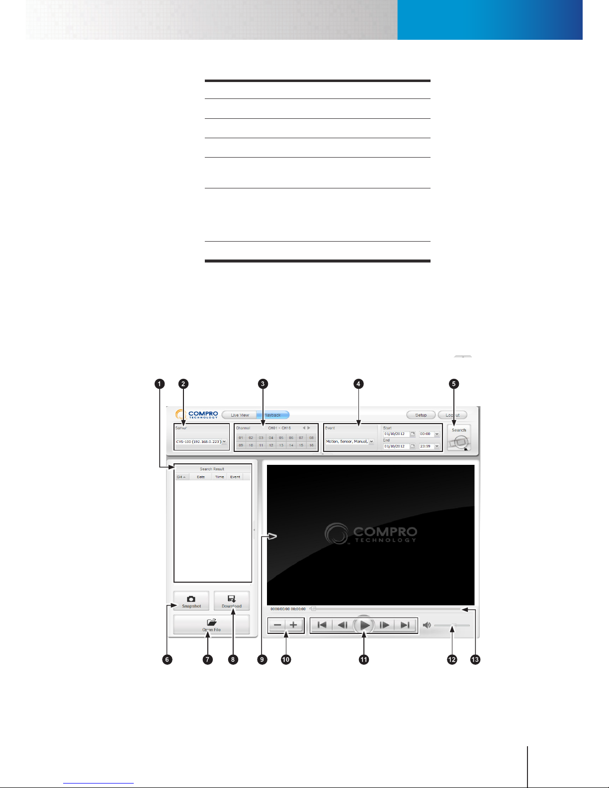
Remote Playback on WebVUer
Chapter 11: Remote Access
11-7
Item Description
Setup Enter channel setting.
Record Initiate video recording.
Stop Recording Stop video recording.
Event Playback Search RS-3232 for video recordings that
capture events detected on this channel.
Digital PTZ Enable or disable the digital PTZ function for
the selected channel. Use the PTZ control
and zoom control buttons to perform digital
PTZ.
Information Display channel information.
Table 11-3. WebVUer right-click menu
Remote Playback on WebVUer
Playback Page Layout
On the playback page, you can see the search panel at the top, and the search result pane on the left-hand
side, and the playback control panel on the lower-right side. You can click on the arrow icon to hide
or show the top or left control panel.
Figure 11-8. Playback page
Page 90
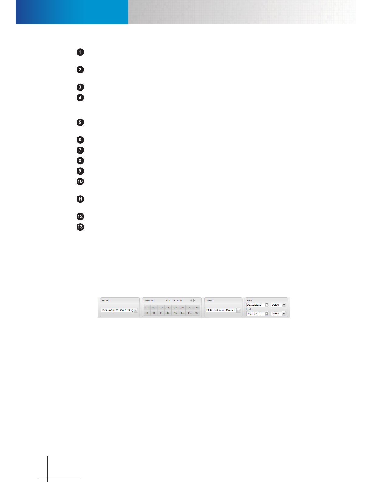
Remote Playback on WebVUer
Compro RS-3232 - User's Manual
11-8
Search result panel – Here it displays the results based on your search criteria. Double-click any found
item to start playing back. You can sort the search result by clicking on any column header.
Server Filter – If you have added more than one server (RS-3232) to the server list, you can click on the
combobox and choose which server you want to search.
Channel lter – Select the channel(s) on this server to search.
Event and Time lter – Click the event combobox to choose the event type(s) you would like to use to
search for recordings. Then put in the start time and end time to delimit a time range for search. The
default time range is designated as one day before current system time.
Search button – Press the button to search ComproView® database on RS-3232 based on current
search criteria.
Snapshot button – Allows you to take a snapshot of the current video frame in the video pane.
Open le – Open a recording stored on your remote viewing PC and play it in the browser window.
Download – Download the retrieved recording you've selected from the search result pane.
Video window – Displays video.
Playback speed – "Plus" button for increasing playback speed; "minus" button for slowing down
playback.
Playback control – From left to right: 'jump to the beginning', 'previous frame', 'play/pause', 'next
frame', 'jump to the end.'
Volume control – Drag the slider to adjust volume; click the speaker icon to mute/ unmute.
Seek bar – Drag the seek bar to any position to start playing from that specic point.
Search for and Play Recordings
The following parts explains how to search for recordings, play back recordings, take snapshots, and
download recordings from RS-3232 on the Playback page of ComproView® WebVUer.
Search for Recordings
To search for recordings, you need to set your search criteria before hitting the [Search] button, which
can be done using the Time/Channel/Event lter.
Figure 11-9. Time/ Channel/ Event lter
• Time Filter: Time lter lets you designate the time range to run your search. The default time range is
within the current day.
• Channel Filter: Click the channel number to select or deselect any channel. Click the left arrow or right
arrow to switch between the 1st and 2nd 16 channels.
• Event Filter: Event lter allows you to search for recordings initiated by an event trigger. By default, all
the event types are selected. Click the event combobox to tailor your selection.
After you have set your search criteria, press the [Search] button in the upper-right hand side. WebVUer will
then search RS-3232 database for any recordings that meet your search criteria. Recordings matching your
criteria, if available, will then turn up in the Search Result pane on the left.
Page 91

Remote Playback on WebVUer
Chapter 11: Remote Access
11-9
Play Back Recordings
To play back video stored in the ComproView® database on the RS-3232:
1. Log in to RS-3232 remotely on your web browser. Then go to the Playback page.
2. Set you search criteria and then press [Search]. Wait until results turn up in the "Search Result" pane.
3. In the "Search Result" pane, double-click on any found items to start playing back. Or select one
recording item and then hit the playback button .
To play back video stored on your remote viewing PC:
1. In the playback page, press [Open File] in the lower-left corner.
2. Choose a local video clip from your viewing PC.
Take a Snapshot
To take snapshot of the current video frame in the video pane:
1. Log in to your NVR's playback page.
2. Use the Time/ Channel/ Event lter to set your search criteria. Then press [Search] and double-click on
any item in the search result pane to start playback. Or hit the [Open File] button to open a video clip
on your PC and start playback.
3. Click on the seek bar (or drag it) to move to the desired playback position, and then press the Pause
button.
4. Use the [Next Frame] or [Previous Frame] button to move to the exact position. Click the [Snapshot]
button to save the image. The snapshot will be saved under "My Documents" by default.
Download a Recording
To download a video recording from the RS-3232 to your remote viewing PC:
1. Log in to RS-3232 remotely on your web browser. Then go to the Playback page.
2. Use the Time/ Channel/ Event lter to set your search criteria, and then press [Search].
3. Select any item that turns up in the search result pane. The hit the [Download] button.
4. The "File Download" window pops up. Choose [Save] to save it on your PC, or choose [Open] to open
the le directly.
Page 92

Remote Playback on WebVUer
Compro RS-3232 - User's Manual
11-10
Page 93
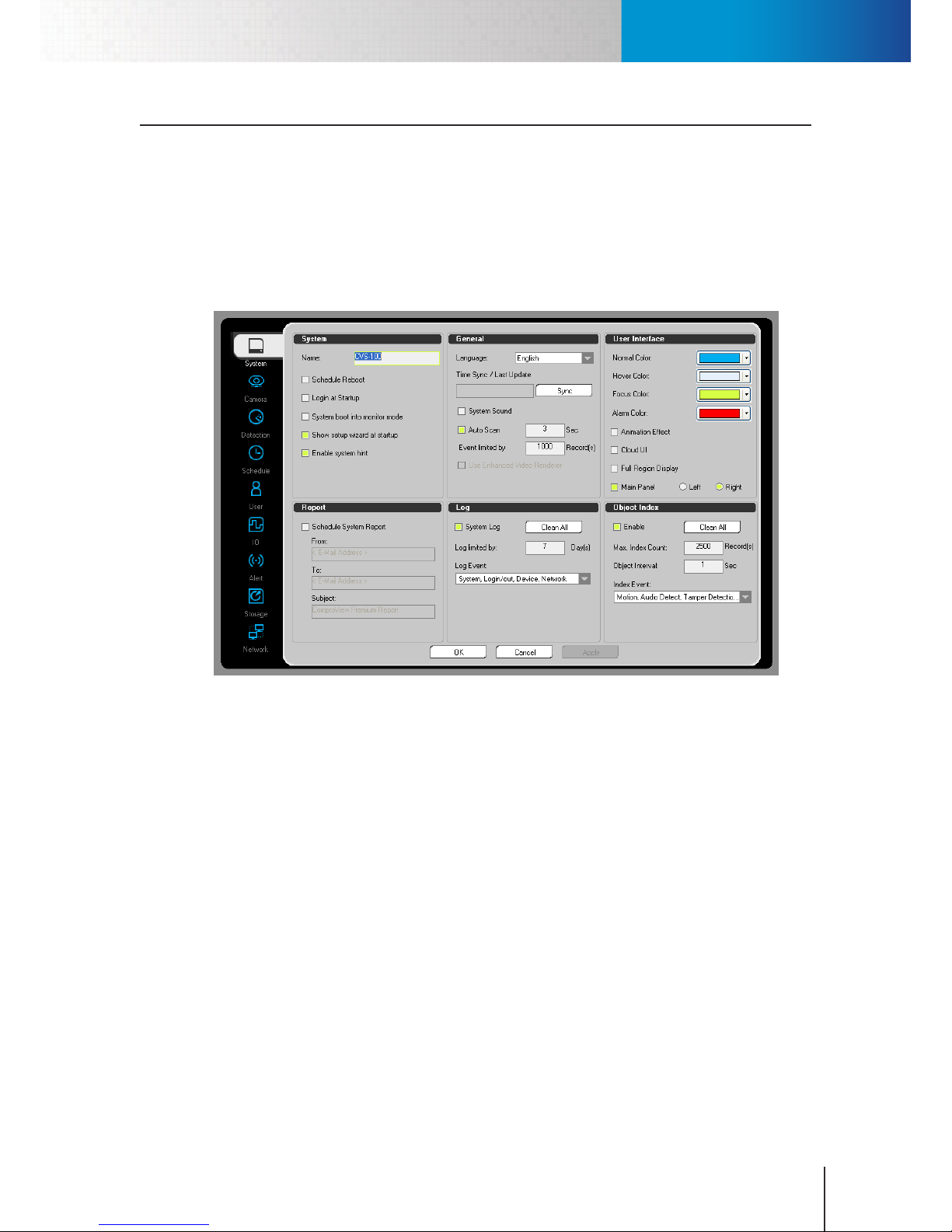
System Tab
Chapter 12: Conguration
12-1
Chapter 12: Configuration
The system configuration console provides all the detailed settings with regard to camera connection, video
analytics, storage, network, etc. The system conguration console can be accessed by clicking the Setup (wrench)
icon in the utility panel and choosing “Setup” from the fly-out menu. The system configuration console contains
several tabs (System, Camera, Detection, Schedule, User, IO, Alert, Storage, Network). Click on any icon on the lefthand side of the system conguration console to switch to a dierent tab. The followings are the explanations of the
8 tabs in the system conguration console.
System Tab
Figure 12-1. System tab
System Settings
• Schedule Reboot: Enable or disable scheduled reboot. Go to the "Schedule" tab and schedule a system
reboot operation rst before you enable this option.
• Login at Startup: Check this option to require user login before entering ComproView®.
• System boot into monitor mode: When checked, this option allows ComproView® to enter monitoring
mode automatically after a user logs in. Besides, if you opt for adding ComproView® to the startup folder
of your Windows system during the installation of ComproView®, enabling this option will allow you to
launch ComproView® and start monitoring right away after the system starts up.
• Show setup wizard at startup: Check this option to display the quick setup wizard after logging into
ComproView®.
• Enable system hint: Check to enable system message.
• Loading Limitation: When checked, this option allows the system to automatically adjust video frame
rate for better balancing system loading.
General Settings
• Language: This allows you to change the language of user interface.
Page 94
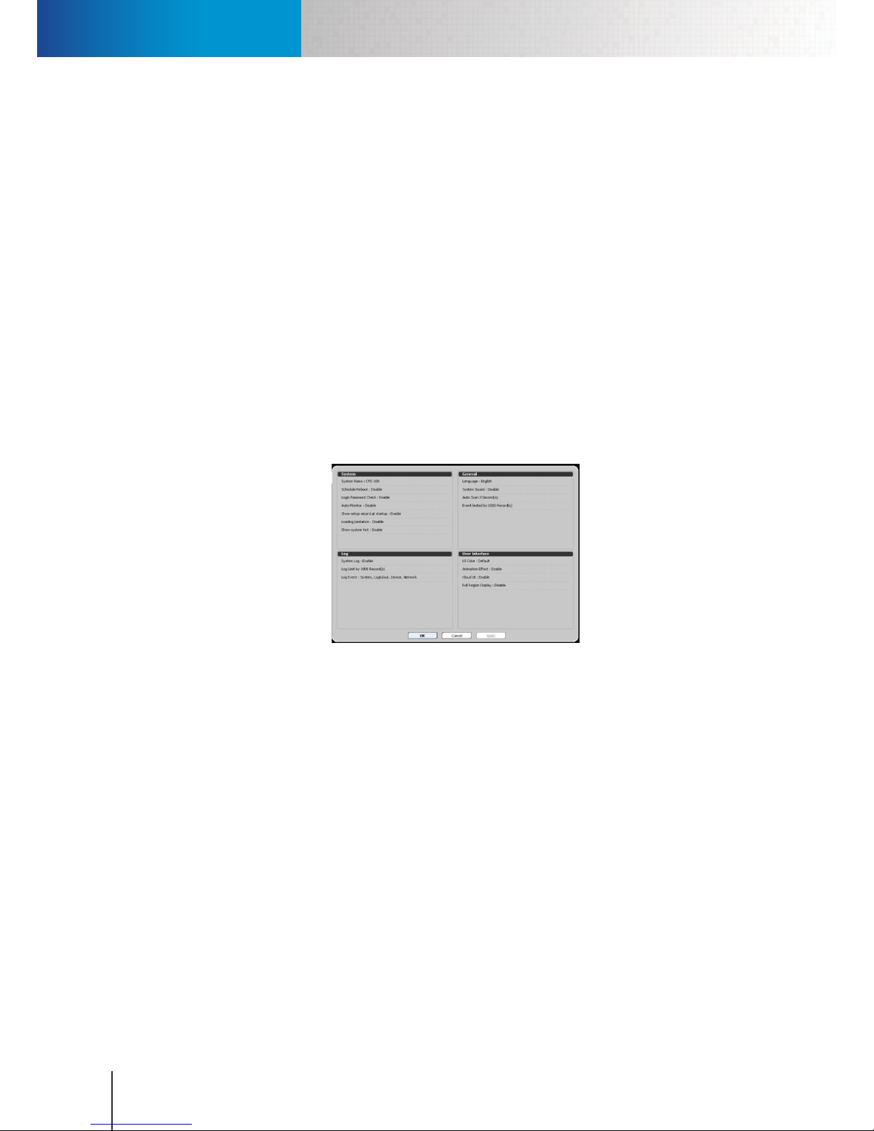
System Tab
Compro RS-3232 - User's Manual
12-2
• Sync (time): This will synchronize the system clock with that of your operating system.
• System sound: This will turn on / o the system sound.
• Auto scan: Allow you to enable/disable the Auto-Scan function, which makes ComproView® sequentially
display the next channel in a split view. When the next channel has not been congured with camera
connection, the next next channel will be pulled up instead. The number of seconds entered here
dictates how long the split view dwells on current channel combination. In single channel view, the
dwell time is decided by the value of “Auto Scan Duration” in the Camera tab.
• Even limited by: Cap the maximum number of records in the event log.
• Use Enhanced Video Renderer: This option is only accessible for Windows Vista and Windows 7 user.
User Interface Settings
• Normal / Hover / Focus / Alarm Color: This lets you customize the colors used in the user interface and
the status they represent.
• Animation Eect: Check to enable the y in / out animation when a window is opened / closed.
• Cloud UI: Check to switch to another style of user interface. In the Cloud UI, you can click on any menu
item to change its setting.
Figure 12-2. Cloud UI
• Full Region Display: Check to make ComproView® occupy the entire section of your screen.
• Main Panel (Left/Right): Change the position of ComproView® main panel.
Report Settings
• Schedule System Report: Enable or disable the scheduled system report function. Two pre-requisites
must be met in order to send out system report successfully. First, you have to go to the "Alert" tab and
set up a valid E-mail service. Second, you need to go to the "Schedule" tab and schedule a system reboot
operation. After that, in the "System" tab, enter the sender and recipient information and subject for the
system report E-mail. The following is an example of system report received via E-mail.
Page 95
System Tab
Chapter 12: Conguration
12-3
[ Channel 1 ]
Name : Channel-1
Connect : Enable
Signal : Enable
Status : Preview
**Followed by other channels
[ Storage 1 ]
Path : D:\Documents and Settings\User\My Documents\Compro\ComproView® Premium
Capacity : 200.43 GB
Used Space : 101.24 GB
Free Space : 99.19 GB
Figure 12-3. System report example
Log Settings
• System log: Enable / Disable system log function. You can also specify the maximum number of records
and the type of events contained in the system log.
• Log limited by: Specify how long the logs will be kept in the system .
• Log Event: Specify the type of events to be recorded in the system log. (System, Login/out, Device,
Network.)
Object Index Settings
• Enable: Check to enable or disable object index function.
• Clear All: Clear all object index records.
• Max. Index Count: Specify the max. number of index records.
• Object Interval: Determine the interval between each indexing. The default setting is 1 second, which
means in a 1 second period, ComproView® will only index the rst event that happens if multiple events
occur within the same period.
• Index Event: Choose the types of event, either detected by ComproView® or IP camera, that can trigger
an event index.
Page 96
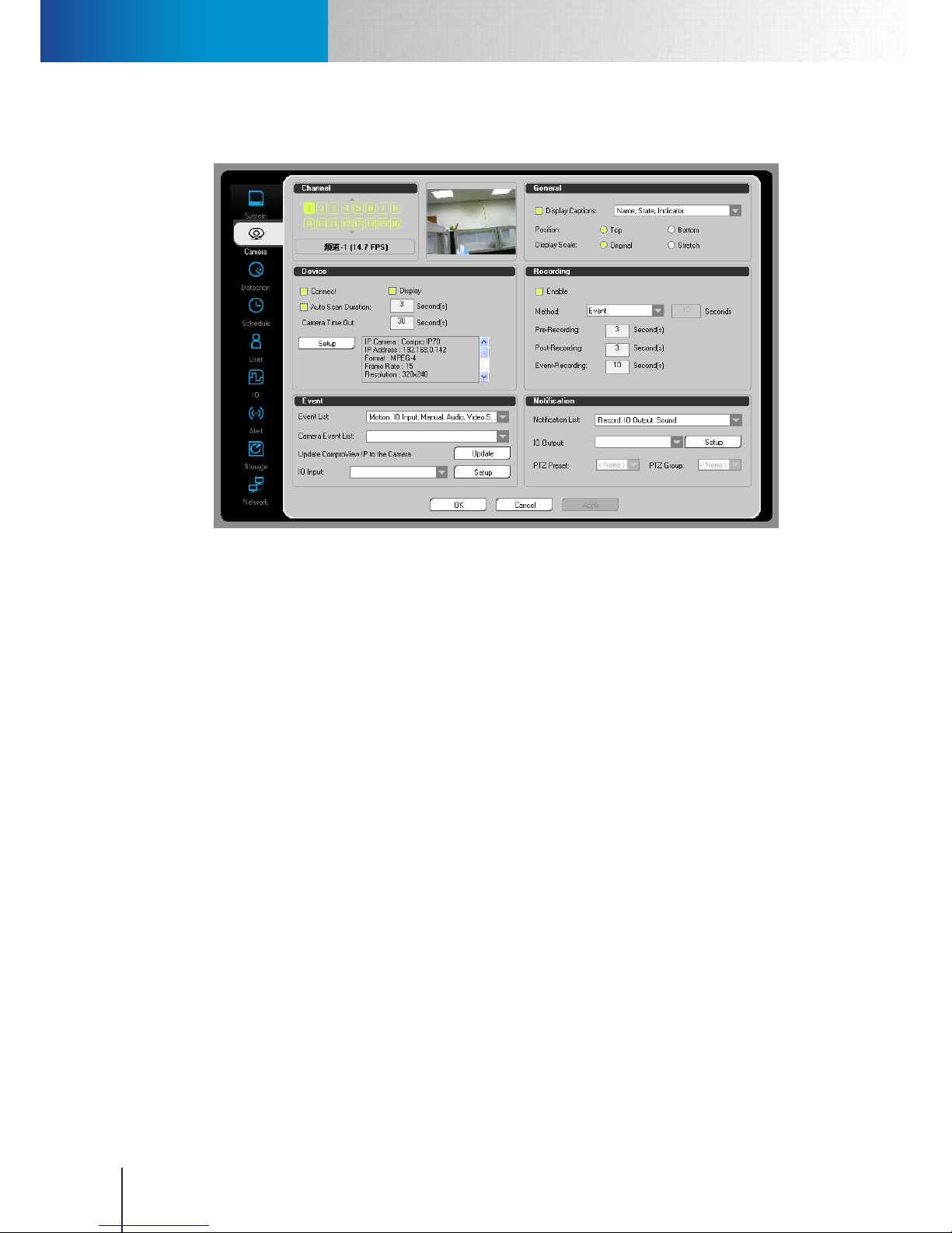
Camera Tab
Compro RS-3232 - User's Manual
12-4
Camera Tab
Figure 12-4. Camera Tab
Channel Settings
This section lets you click on a channel button to select a channel (up to 32 channels) to display the
channel preview.
General Settings
• Display Captions (Name, Date, Time, State, Indicator, and Network Information): Select what
additional information will be displayed on the channel video pane.
• Position (Top / Bottom): The position of the captions on the video pane.
• Display Scale (Original / Stretch): Select the aspect ratio for this channel. You can maintain the original
ratio or stretch camera image to match the dimensions of the video pane.
Page 97
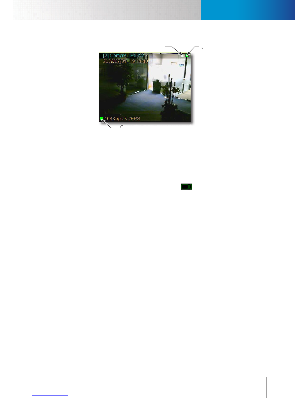
Camera Tab
Chapter 12: Conguration
12-5
Motion detection
status
Status for other
detections
Connection status ; green means good
quality; orange means sporadic stutter;
red means frequent frame drops
Figure 12-5. Status indicator on video pane
Device Settings
• Connect: Check to initialize connection for the selected channel after logging into ComproView®.
• Display: Determine if ComproView® should decode the video stream and display the video in the
channel pane. If you uncheck this option, a camera icon ( ) showing video is not decoded will
appear in the video pane of selected channel. Motion-based recording and snapshot taking are not
allowed if video is not decoded.
• Auto scan duration: In single channel view, when you click the Auto-Scan icon to sequentially display
the next channel, the dwell time is decided by the value of “Auto Scan Duration” (1-60 sec).
• Camera time out: Determine when to show connection failure when connection times out (3-60 sec.).
• (IP camera) Setup: You can also set up your camera connection in the camera tab of the system
conguration console. Simply select the channel you wish to set up using the channel buttons in the
Channel section, and hit the [Setup] button in the Device section to bring up the camera setup window
as shown below.
Page 98
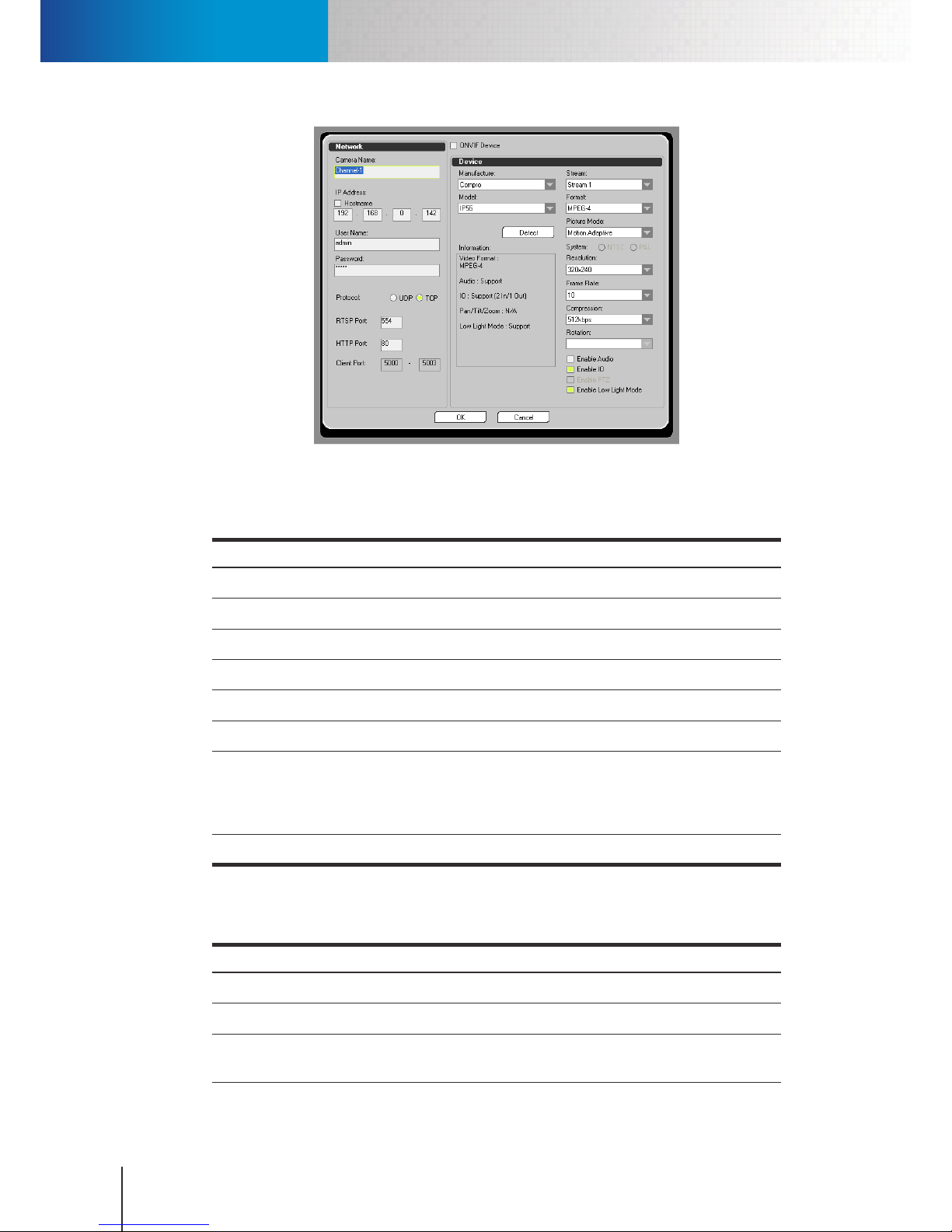
Camera Tab
Compro RS-3232 - User's Manual
12-6
Figure 12-6. Camera setup window
The information section (in the gure above) displays support information from the IP camera you are
connecting to. The parameters in the Network section are explained below.
Item Description
Camera Name Enter the channel name to be displayed on the video pane.
IP Address Enter the IP Address of this IP camera.
User Name Enter the user name required for accessing this IP camera.
Password Enter the password required for accessing this IP camera.
RTSP Port Enter the RTSP port number this IP camera uses
HTTP Port Enter the HTTP port number this IP camera uses.
Protocol
Select between UDP or TCP. When you are connecting to an IP camera located
on the Internet (namely the camera is connected via its WAN/public IP address),
make sure you use TCP protocol for this camera connection. Using UDP
connection in this case may result in blank screen on this channel..
Client Port Enter the client port (Default 5000-5003).
Figure 12-7. Parameters in the Network section
The parameters in the Device section are explained below.
Item Description
Manufacturer IP camera’s manufacturer.
Model IP camera’s model number.
Stream Determine which video stream to be used for live view/recording (depending on
camera support).
Page 99
Camera Tab
Chapter 12: Conguration
12-7
Item Description
Format Video compression format.
Frame Rate How many frames per second.
Resolution Video resolution.
Compression
Video quality determined by bitrate; higher bitrate leads to higher quality but
also higher bandwidth consumption.
Rotation Rotate the image by 180 degrees if the camera is mounted on the wall/ceiling.
Enable Audio Enable/disable audio stream.
Enable IO
Enable the signal receiving from digital input sensor to control digital output
relay.
Enable PTZ Enable the control of Pan/Tilt/Zoom if supported by the camera.
Enable Low Light
Mode
Adjust exposure level to enhance picture quality when the ambient light is
insucient.
Figure 12-8. Parameters in the Device section
When ready, press [OK] to exit IP camera setup window. Then press [Apply] to save the changes. When
you return to the main workspace, right-click on the video pane of the channel you’ve just congured
and choose “Connect” to connect to the IP camera.
Recording Settings
• Recording: To Enable / Disable Recording on selected channel.
• Method: Three recording methods are available in ComproView®. They are Non-Stop, Event, and Time-
Lapse recording.
• Non Stop recording: This is continuous recording. Once enabled, ComproView® will record video on
user selected channel(s) .
• Event recording: Select this mode to only start recording when an event is triggered. At least one type
of detection (Motion, or Audio) needs to be enabled to trigger recording.
• Time Lapse recording: Select this mode to start recording only when an event is triggered, and to stop
recording when an amount of time dened by user lapses. At least one type of detection (Motion or
Audio) needs to be enabled to trigger recording. In this mode, ComproView® will record the amount of
time dened by Time Lapse setting, regardless of the duration of an event.
• PreRecording: Determine how many seconds of video the system records immediately preceding the
time point at which an event is triggered. (0-30 sec.)
• PostRecording: Determine the recording duration for each triggered event. (0-30 sec.)
• Event recording: 1-120 sec.
Event Settings
• Event list: Lets you choose the types of events that can be detected by ComproView® and can be used
to trigger event notications and actions. You can choose one or more of these events to monitor. If you
choose motion detection or any other detections, you also have to make sure that motion detection (or
Page 100

Camera Tab
Compro RS-3232 - User's Manual
12-8
any other detections) are enabled and congured in the Detection tab. The list contains the following
items:
Motion: when motion event is detected, action will be taken (from notication list).
IO Input: when IO input is detected, action will be taken (from notication list).
Manual: when manual event triggers, action will be taken (from notication list).
Audio: when audio event is detected, action will be taken (from notication list).
Video Signal Loss: when video signal loss is detected, action will be taken (from notication list).
• Camera Event List: Lets you choose the types of events that can be detected by your IP camera and
can be used to trigger event notications and actions. You can choose one or more of these events to
monitor.
• Update ComproView® IP to the Camera: Click to update the up-to-date address of the Notify Server to
your Compro IP camera.
• IO Input: Select the sensor for IO input, or you can click the “Setup” button to set up sensor from IO
devices setup.
Notication Settings
• Notification List: Lets you determine what types of notifications can be sent. You can choose one
or more of these notifications to activate when an event is triggered. You also need to make sure
corresponding notication setting is congured in the Alert tab. The list contains the following items:
IO Output: when an event is triggered, IO Output will send out a signal (I/O needs to be enabled
beforehand).
PTZ: when an event is triggered, PTZ preset points / patrol group movement will begin (PTZ preset
points and patrol groups need to be dened rst).
Zoom: when an event is triggered, ComproView® will switch to single channel view that displays the
channel on which an event is detected.
Screen: when an event is triggered on a channel, the video pane will begin ashing to notify the user.
• IO Output: Select the IO device to trigger. Hit [Setup] to go to the IO tab to congure your camera's IO
devices.
• PTZ Preset: When an event is triggered, move your PTZ camera to a preset position. (Only available for
PTZ cameras.)
• PTZ Group: When an event is triggered, start the selected patrol tour for your PTZ camera, which makes
the PTZ camera rotate through dierent predened camera positions. (Only available for PTZ cameras.)
 Loading...