

Page 1

IP540/IP540P
Page 2

IP540(P) User’s Manual
Copyright © 2001-2010. Compro Technology, Inc. No part of this document
may be copied or reproduced in any form or by any means without the prior
written consent of Compro Technology, Inc.
Compro, VideoMate, Poladyne, Play with Power, and the Compro logo are
trademarks of Compro Technology, Inc. Other names and marks are
trademarks of their respective owners.
COMPRO makes no warranties with respect to this documentation and
disclaims any implied warranties of merchantability, quality, or fitness for any
particular purpose. The information in this document is subject to change
without notice. COMPRO reserves the right to make revisions to this
publication without obligation to notify any person or entity of any such
changes.
Compro Technology, Inc.
www.comprousa.com
Tel. +886 2 2918 0169, Fax +886 2 2915 2389
4/F, No.12, Alley 6, Lane 45, Pao Shin Road Hsintein City, Taipei, Taiwan.
Support e-mail: [email protected]
Page 3

IP540(P) User’s Manual
Table of Contents
Important Safety Notice............................................................................... 4
Product Overview ........................................................................................ 5
Package Contents ....................................................................................... 5
Product Description ..................................................................................... 6
Key Features .............................................................................................. 7
Specifications .............................................................................................. 8
System Requirements ................................................................................. 9
Hardware Installation ................................................................................ 10
Hardware Overview (Name of Each Part) ................................................. 10
Connect Your IP Camera .......................................................................... 11
Wireless Connection ................................................................................. 12
Mounting on the Wall or Ceiling ............................................................... 14
Software Installation .................................................................................. 15
Controls the IP camera in Internet Explorer .............................................. 29
Configuring the IP camera ........................................................................ 32
Access the IP Camera via iPhone/mobile device .................................... 49
Access the IP Camera via 3GPP Mobile Phone ....................................... 50
The Internet Setting ................................................................................... 51
DDNS Setup and Port Forwarding ............................................................ 52
Firmware Update........................................................................................ 56
Troubleshooting ........................................................................................ 57
Initial Hardware / Software Setup .............................................................. 57
Trouble with the ActiveX Client ................................................................. 59
Remote Viewing via Internet Explorer ....................................................... 62
Page 4
IP540(P) User’s Manual
Important Safety Notice
Please follow the steps below to protect your IP camera:
Please place the IP camera on a level surface and out of direct sun shine.
Please keep the IP camera inside house and away from water, dust,
humidity or magnetic products.
Please do not drop the IP Camera body to the floor; it may cause the
damage to main parts.
Please do not disassemble or remodel the product, it may cause damage
or fire.
Do not shake, move or disturb the IP camera when it is in operation, as
such actions may result in the malfunction of the device.
Power off the IP Camera as soon as it is found smoking or smelt unusual.
Please do not place the IP Camera around the heat sources, such as
television or microwave oven.
Please do not rotate your IP camera by hand. It may cause the damage of the
IP camera.
Page 5

IP540(P) User’s Manual
Product Overview
Package Contents
Please check the package contents on your hand, if anything is missing,
please do not hesitate to contact with your local distributor.
Please do not use the adaptor that not from Compro technology, it may cause
damage of your IP camera.
IP540(P)
Network Camera
RJ-45 LAN
Cable
Power Adaptor
(12V, 2A)
Installation CD
Installation Guide
Screw for Ceiling Mount x 3
Screw Mount x 3
Camera pad x4
Wall plate
Power Cable
Page 6

IP540(P) User’s Manual
Product Description
Compro IP540(P) camera series offers an advance 340-degree panning with
100-degree tilting mechanical design for continuous movement, ideal for live
monitoring locations need to follow a person or objects such as home,
warehouse, small business or restaurant lobby area.
Pan/Tilt with 10X digital zoom
IP540(P) delivers simultaneous H.264 and MPEG-4 or MJPEG video stream,
together with high performance megapixel sensor allowing for optimization in
image quality and network bandwidth. The camera provides 30 preset
positions and 1 preset sequence to monitor specific areas. Provided with
digital zoom feature, users can magnify any area on the real-time video
display by a maximum factor of 10
Day & Night Support for Any Lighting Condition
IP540(P) features an unique design of its class integrating a professional class
of light sensor IR solution for 24 hours 7 days surveillance under any lighting
condition. A light sensor will turn on an array of IR LEDs to illuminate the
scene automatically when the lighting condition is dark for image clarity and
switch off the IR LEDs when the lighting condition turns normal.
Two-way Audio Support
IP540(P) provides two-way audio support of a build-in microphone with an
audio jack for external speaker, allowing remote listening of the area via direct
voice communication or pre-recorder audio clips.
Easy Wireless Network Installation
802.11 b/g/n wireless LAN is supported via the WL150 USB upgrade module
with a simple and easy wireless installation process. (Optional Accessory)
Total Surveillance Solution for Home and Business
IP540(P) bundles a full range of applications to provide an intelligent
surveillance total solution - iWizard is a smart installer to turn the complicated
network camera installation to a simple and fast process; WebVUer is an
intuitive IE based video management software includes all the key features for
trouble-free monitoring home surveillance; ComproView is a powerful feature
rich 32 channels professional grade multi-camera video management solution
for business surveillance.
Page 7

IP540(P) User’s Manual
PTZ I/O Alarm Expansion Box (Optional)
IP540(P) provides up to 6 alarm Inputs/Outputs function with an optional PTZ
I/O Alarm Expansion Box.
Power over Ethernet (PoE)
The Power-over-Ethernet technology is now supported. PoE technology
allows network camera to harness electrical power over Ethernet cable while
using it to carry data in/out of the camera, eliminating the need for a power
cable and adaptor when AC power outlet is not available or inconvenient on
site. *Note: only applicable to models containing P designation.
Key Features
1/3" CMOS progressive scan sensor
Pan, Tilt, 10x digital zoom
(Pan of 340 degrees, Tilt of 100 degrees)
Day and night functionality with mechanical IR cut filter switching
Built-in IR LEDs x12
Supports real-time H.264, MPEG-4 and MJPEG compression (Triple
Codec)
Supports dual streams simultaneously
Image frame rate is up to 30 frames per second at 640x480 resolution
Smart motion detection
Two way audio with built-in MIC (External speaker not supplied)
Support UPnP (Universal plug and play)
Support 10/100 802.3/Ethernet
Optional 802.11b/g/n WLAN upgrade module
Supports local storage (MicroSD/SDHC)
Easy to Install with IP Cam Wizard
Remote Monitoring from 3GPP Mobile
Bundle with powerful 32-channel IP video management software ---
ComproView
Optional Digital I/O box for External Sensor and Alarm (3 In/3 Out)
Supports Power-over-Ethernet (540P only)
Page 8

IP540(P) User’s Manual
Specifications
Image Sensor
1/3" CMOS sensor
Lens
Focal Length: 4.0 mm
Max Aperture Ratio: F1.5
Fixed iris
Pan range
-170° ~ +170° total of 340 degree
Tilt Range
-10° ~ +90° total of 100 degree
Max Speed
Pan 90°/Sec., Tilt 70°/Sec.
Zoom
10x digital zoom
Angle of View
60° horizontal
Focusing Range
0.5m ~ INF
Minimum
Illumination
IR Mode: 0 lux; using built-in IR light in darkness
up to 15m
Color Mode: 1.0 lux
Shutter Time
1/5 ~ 1/16000 Sec
Video
Compression
H.264 (MPEG-4 Par t10)
Motion JPEG
MPEG-4 Part 2
Resolutions
160x120, 320 x 240, 640 x 480, 1280 x 1024
Frame Rate
Up to 30 frames at 640 x 480
Up to15 frames at 1280 x 1024
Video Streaming
Dual H.264, MJPEG or MPEG-4 video streams
Image Settings
Adjustable image size and quality
AGC, AWB, AES
Configurable brightness, saturation and
sharpness
Audio
Communication
Two-way audio with built-in MIC
(S/N ratio 58 dB, 50-10000hz )
Audio
compression
G.711 PCM 64Kbit/sec
Audio input /
output
MIC input / Audio out
Security
User ID / Password protection
Supported
DDNS (iDDNS) / PPPoE / HTTP Server / DHCP
Page 9

IP540(P) User’s Manual
Protocols
Client /NTP Client /DNS Client / FTP Client / SMTP
Client / ARP / ICMP/IPV4/ UDP / TCP/IP
Firmware
Support UPnP
Support online firmware update
ComproView
Multiple channel management
iDDNS service for dynamic IP and desktop
shortcut creation
Recording search and playback
Scheduled and event driven management
Smart Detection
Internet Explorer
(ActiveX)
Monitor the current condition of the monitor area
via Internet Explorer
Capture a still image and save it in JPG format on
PC
Alarm and event management: FTP, I/O alarm,
server notification and email
Supported devices
PC, Laptop, Nettop, MID with IE/ActiveX support.
Mobile phone, iPhone/iPod, PDA support in
MJPEG mode.
MJPEG Mode
Viewing of camera image via phone browsers
3GPP Mode
Viewing of camera image via 3G phones
(3GPP Streaming)
Operating
Condition
5 °C ~ 40 °C
Power Supply
PoE (802.3af PoE Class3) for 540P, DC 12V/2A
Dimensions
105 x 125.5 x 128.6 mm
System Requirements
Computer with 1.7GHz processor and 512 MB memory or above
Supported Operating Systems : Windows XP SP3, Vista SP1, Windows 7
x86/x64
Supported Web Browsers (ActiveX): Internet Explorer 6 or later
Page 10
IP540(P) User’s Manual
Hardware Installation
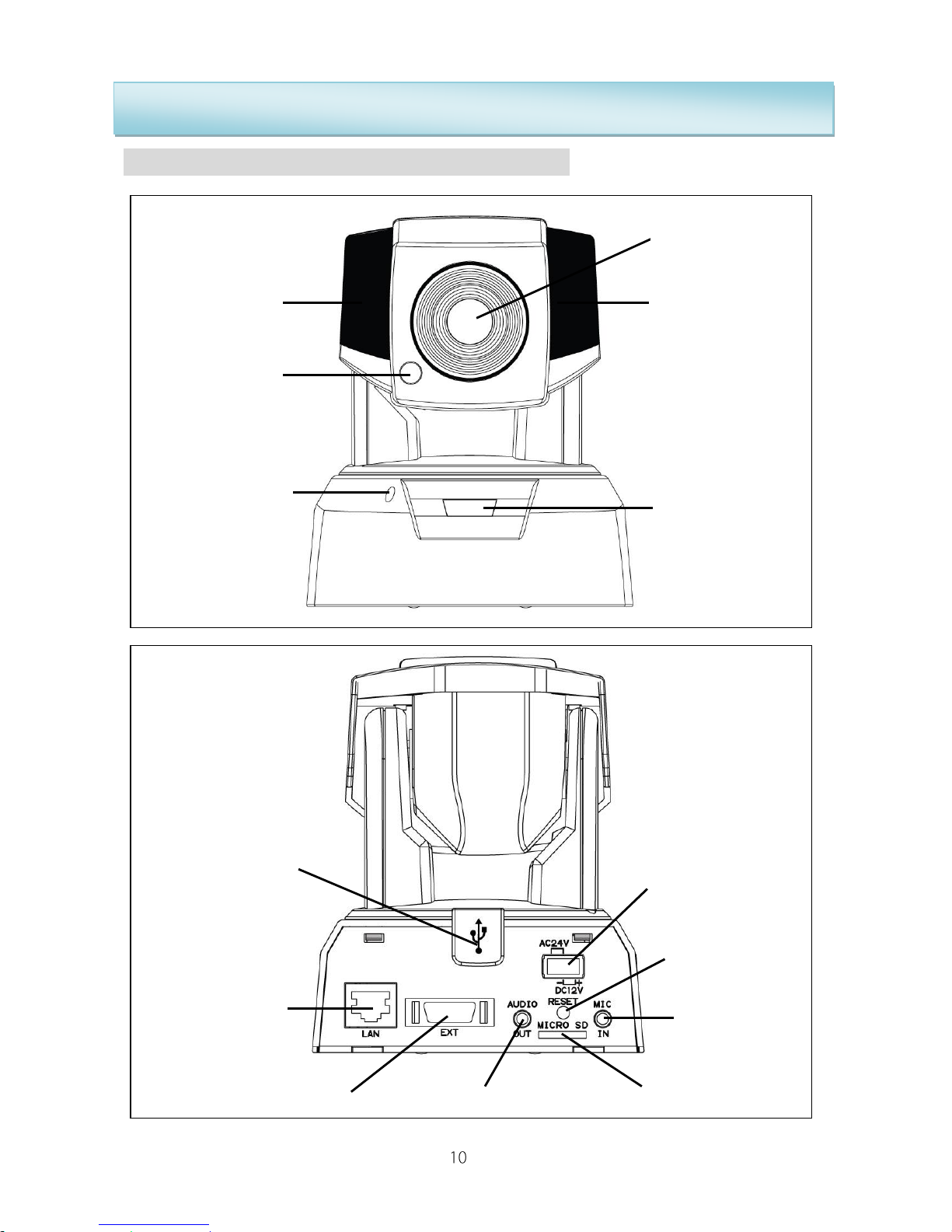
Hardware Overview (Name of Each Part)
Lens
IP Lamp
Light Sensor
IP Lamp
Microphone
LED
Wireless
Adaptor
Connector
(USB type)
LAN
MicroSD/SDHC Card
Microphon
e Input
Power
Audio Output
I/O Box Connector
Reset Button
Page 11
IP540(P) User’s Manual
Connect Your IP Camera
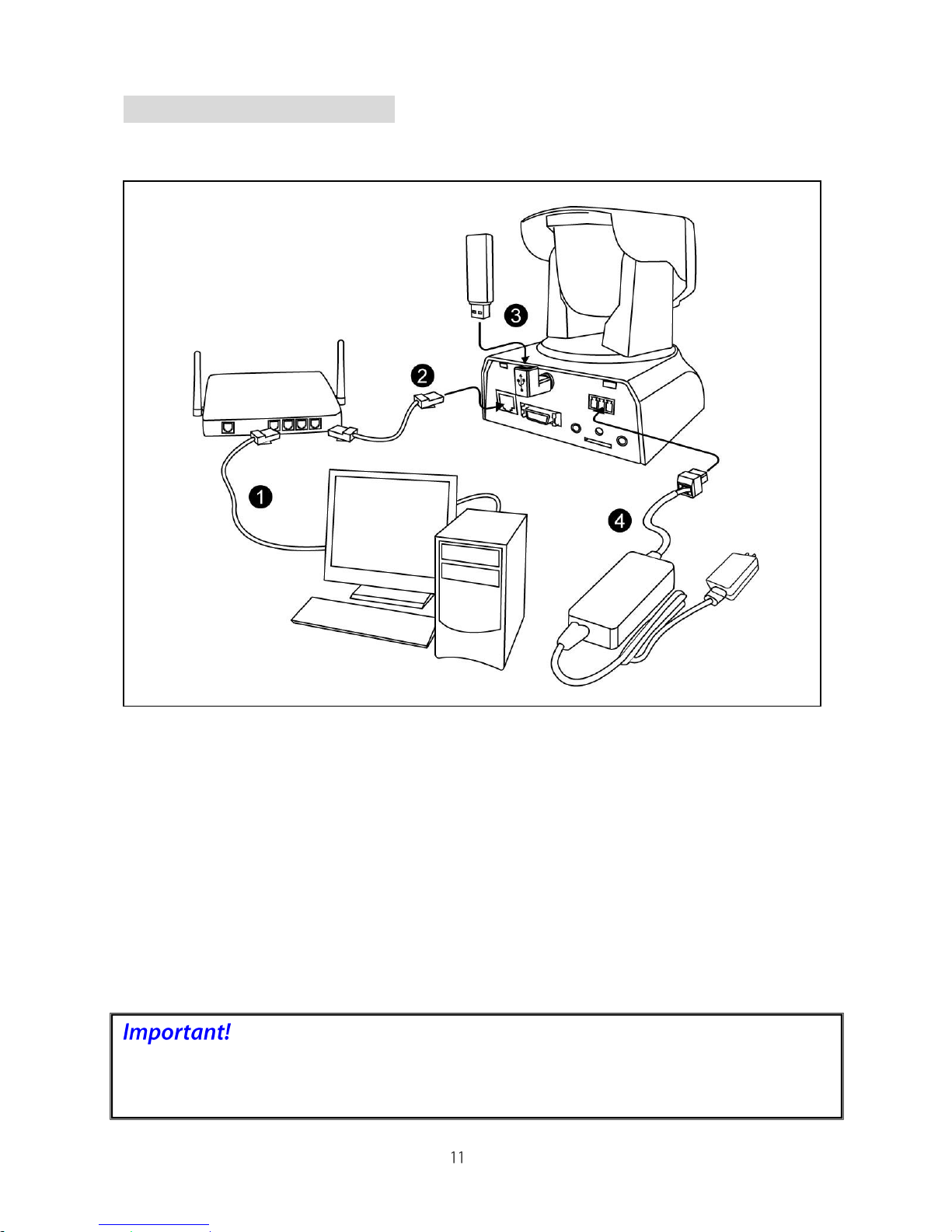
The picture below shows the basic connection of IP540 camera:
1. LAN cable from hub/router to PC: If your LAN cable from PC has been
connected to the Cable/ADSL MODEM before, please re-connect it to the
LAN port of your hub/router.
2. LAN port on camera: Using the bundled RJ-45 LAN cable to connect IP
camera with the LAN port of your hub/router.
3. Wireless adaptor (Optional accessory): If you have purchase the
Compro USB wireless adaptor for wireless connection upgrade, please
plug it into the USB port of IP camera for wireless reception.
4. Power: Attach the power adaptor to the camera’s power socket and
connect it to the power outlet.
Please do not use the power adaptor that not from Compro Technology in the
IP camera.
Page 12
IP540(P) User’s Manual
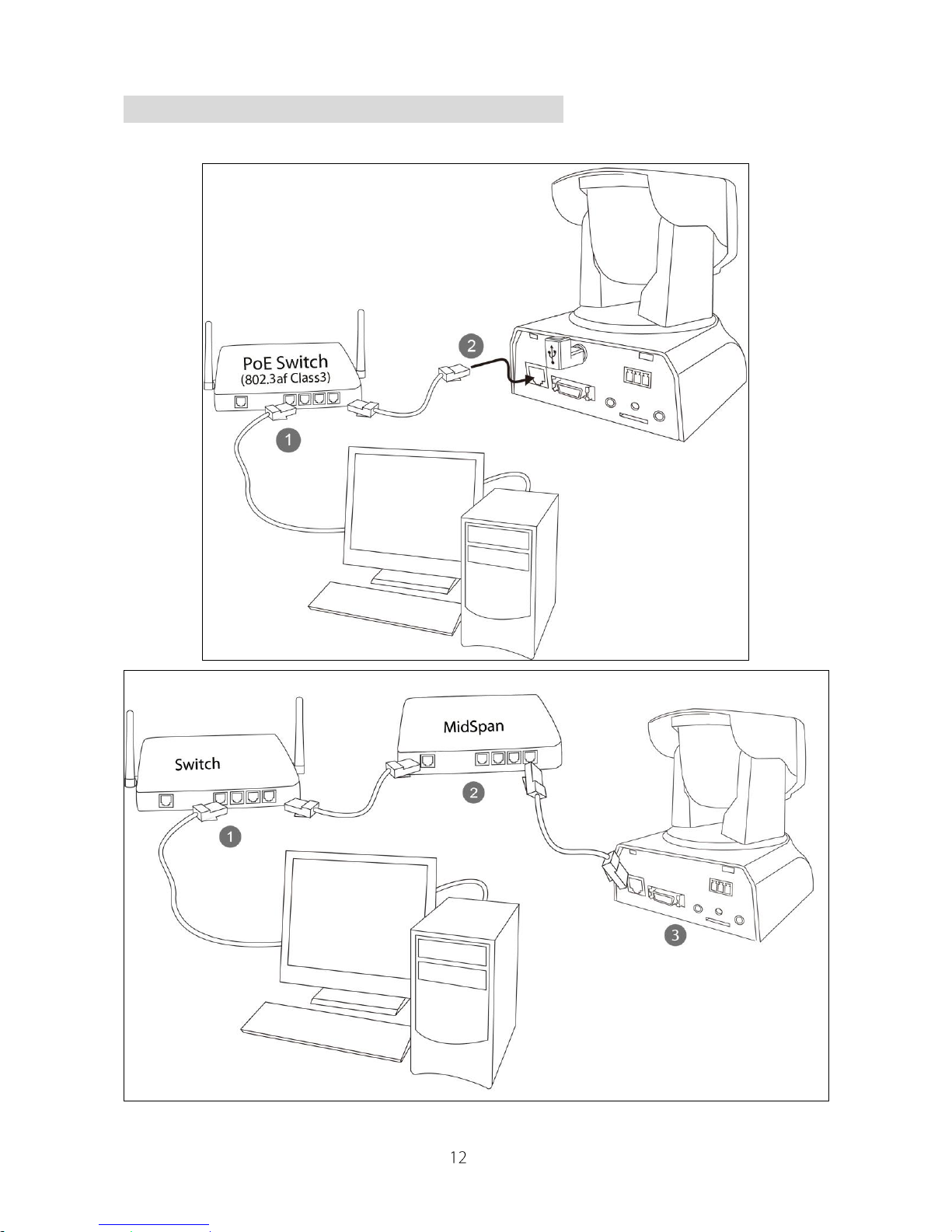
Connect Your Camera with PoE Feature
The illustrations below show how to set up your PoE-capable camera.
Connecting to a
PoE-capable LAN
switch
Connecting to a LAN switch
through a midspan
Page 13

IP540(P) User’s Manual
Wireless Connection
With the IP540(P) wireless adaptor, you also have the option of using the
wireless connection method. Please keep in mind that you can only have one
active connection only, via LAN or wireless.
If user connects the IP camera on the intranet, then the same group of user
can share that IP camera to use. Please ensure that the wireless adaptor had
been securely fastened, otherwise it could lead to unstable connection.
1. The operation of the IP540(P) wireless network may be interfered should
there be other 2.4GHz devices working in the vicinity, e.g. microwave oven,
digital cordless camera, etc. You may experience slow frame rate or drops
in connection; up on such situation, we suggest that you try to move the IP
camera around the area or try to shut off other appliances.
2. Since wireless cameras cause interferences during transmission, you may
encounter erratic behaviors when there are more than 10x operating in
close proximity.
3. The default wireless connection method is via 802.11n standard and you
should experience a stable connection of up to 20 meters between the
access point and the camera unit. Your wireless performance may vary
depending on the operating environment, building material, etc.
Page 14
IP540(P) User’s Manual
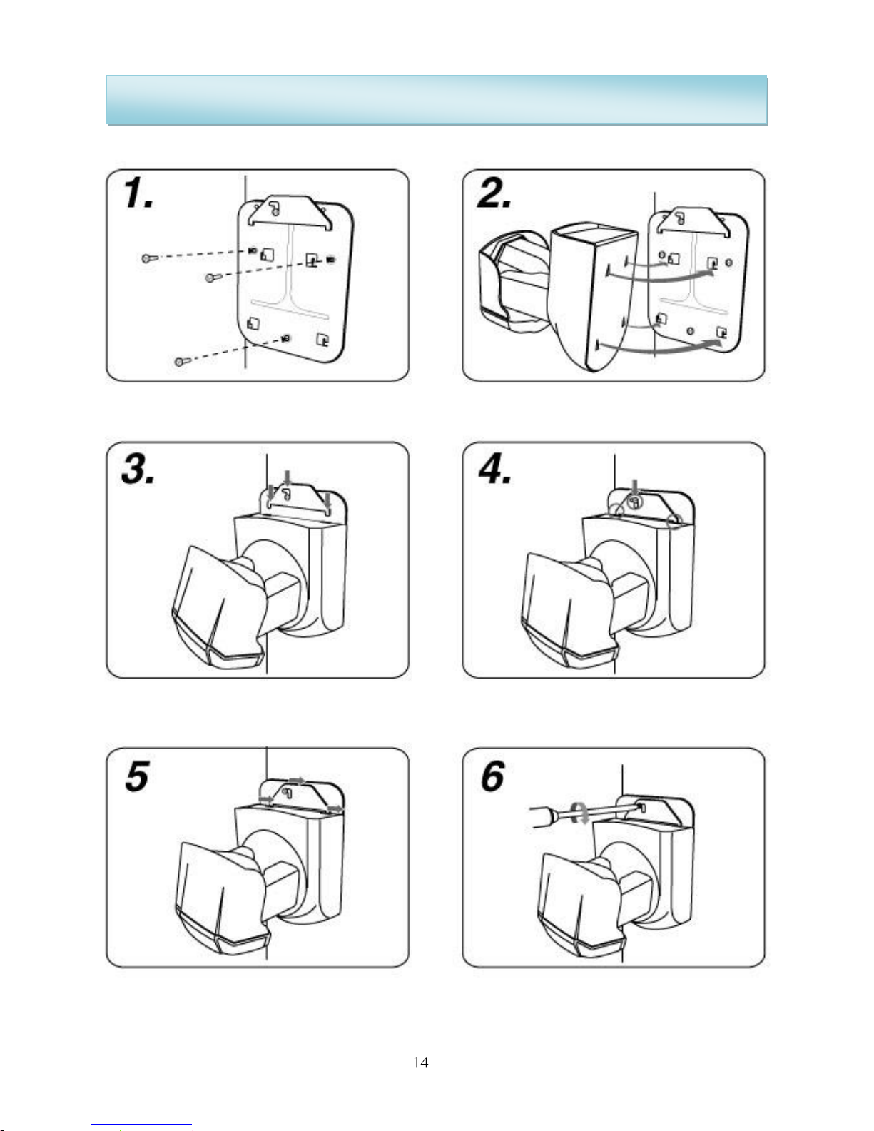
Mounting on the Wall or Ceiling
Tighten the ceiling plate with screws
Put the IP camera on the ceiling plate
Insert the fasten bracket into the camera
Make sure the fasten bracket is complete
insert to the camera
Push the fasten bracket to the right side
Use screwdriver to tighten the screw on the
fasten bracket.
Page 15
IP540(P) User’s Manual
Software Installation
Before Compro software installation, user has to make sure the IP Camera is
beside you. The wizard of ComproView Installer on the installation CD will help
you to step-by-step install IP camera hardware and software on your system.
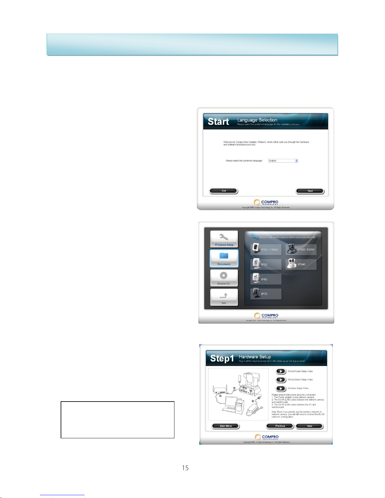
1. Insert the Compro software
installation CD to CD-ROM drive,
the installer will automatic start for
installation, please select the
display language at first.
2. Please click “IP Camera Setup”
and select IP540 / IP540P to install
your IP camera. Also, you can
select other icons to open the
related documents, browse CD
contents, or exit.
3. Step1: Connect your camera as the
picture shown, or you can click to
watch the tutorial video. After
connect all the network and power
cables, please click “Next”.
If you already connect your IP
camera cables, you can skip this
step and click “Next” to continue.
Page 16

IP540(P) User’s Manual
4. Check the LED light of IP camera is
working properly. And click “Next” to
searching your camera.
5. If you see the Windows Security Alert
while searching your camera, please
click “Unblock”.
6. Step2: The wizard will search all the
available cameras from your local
network.
7. You can select your camera from the
list on the left side, and it will display
video live view and camera
information on the right side.
(You can double check the device
name with the MAC ID, the MAC ID
will be print in the serial number
sticker on the back side of IP camera
or in the package box)
Page 17

IP540(P) User’s Manual
8. Step3: We recommend you input
the new password to protect your
system. Or you can click “Next” to
pass this process.
(The default password is “admin”)
9. Please check the camera name, date
and time settings.
10. Select your IP address configuration
by DHCP (Obtain IP address
automatically) or you can manually
input IP address information, allows
iWizard to auto configuration your
firewall, setup connection port, and
frequency of your local power.
11. Select the orientation of your IP
camera in Standard Position or
Ceiling Mount.
Page 18
IP540(P) User’s Manual
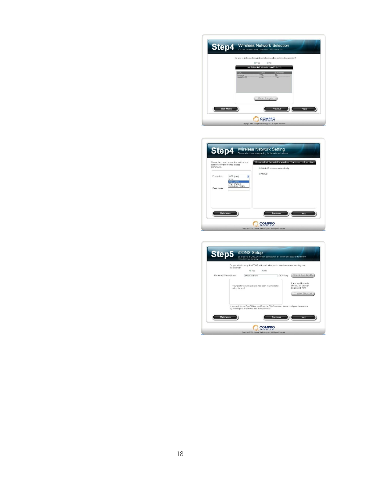
12. Step4: If you already connect the
Compro wireless adaptor on your IP
camera, please click “Yes” and it will
search for the available SSID of
wireless AP/router, please select the
AP/router you want.
13. (For Wireless connection only.) Select
the encryption method and input
passphrase, then select the IP
address configuration.
14. Step5: If you want to use iDDNS
service, please click “Yes” and input
the address name you desire, then
click “Check Availability” to check
the input address name is not being
used by others. When it successes,
you can click “Create Shortcut” to
create the shortcut on your desktop
for more convenient use.
Page 19
IP540(P) User’s Manual
The iDDNS is a free DDNS (Dynamic Domain Name Service) service from
Compro. If you are using floating IP, you need to apply the DDNS service to
create a hostname that points to your home or office IP address, and provides
easy-to-remember URL for quick access in anytime, anywhere. After
succeeded create the iDDNS address name, you only need to using http://xxx
(input by yourself).iddns.org to access your IP camera from browser.
If your local LAN and router have setup firewall to prevent attack from outside,
you have to setup the http port from your router.
For example, if you are setting the http port “2001” for your IP camera, your IP
camera address will be
http://xxx (input by yourself).iddns.org:2001
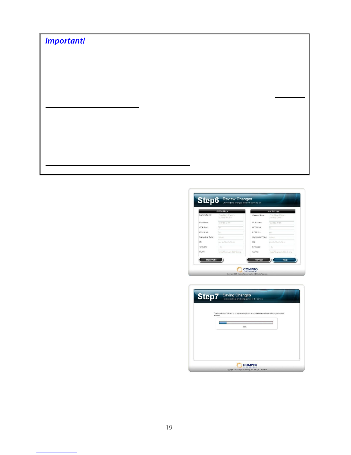
15. Step6: Here will display the old and
new settings, if ok, please click “Next”,
or click ”Previous” back to previous
settings.
16. Step7: System will save and reload
the new settings on your camera.
Page 20

IP540(P) User’s Manual
17. Step8: The iWizard will running
network diagnostics on your network
settings and warning the inappropriate
settings. (In the picture below shows
the RTSP port is not correct setup, you
have to setup the same port as your
router for using the RTSP service.)
18. Step9: You can click the link on the
screen to direct access the web page
of your IP camera, and if you want to
setup another IP camera, please click
“Yes”, or click “No” to install the
ComproView software.
19. You can click “Install ComproView”
to install ComproView software on
your system or you can click “Main
Menu” to exit installation.
20. Select your language for
ComproView software installation.
Page 21
IP540(P) User’s Manual
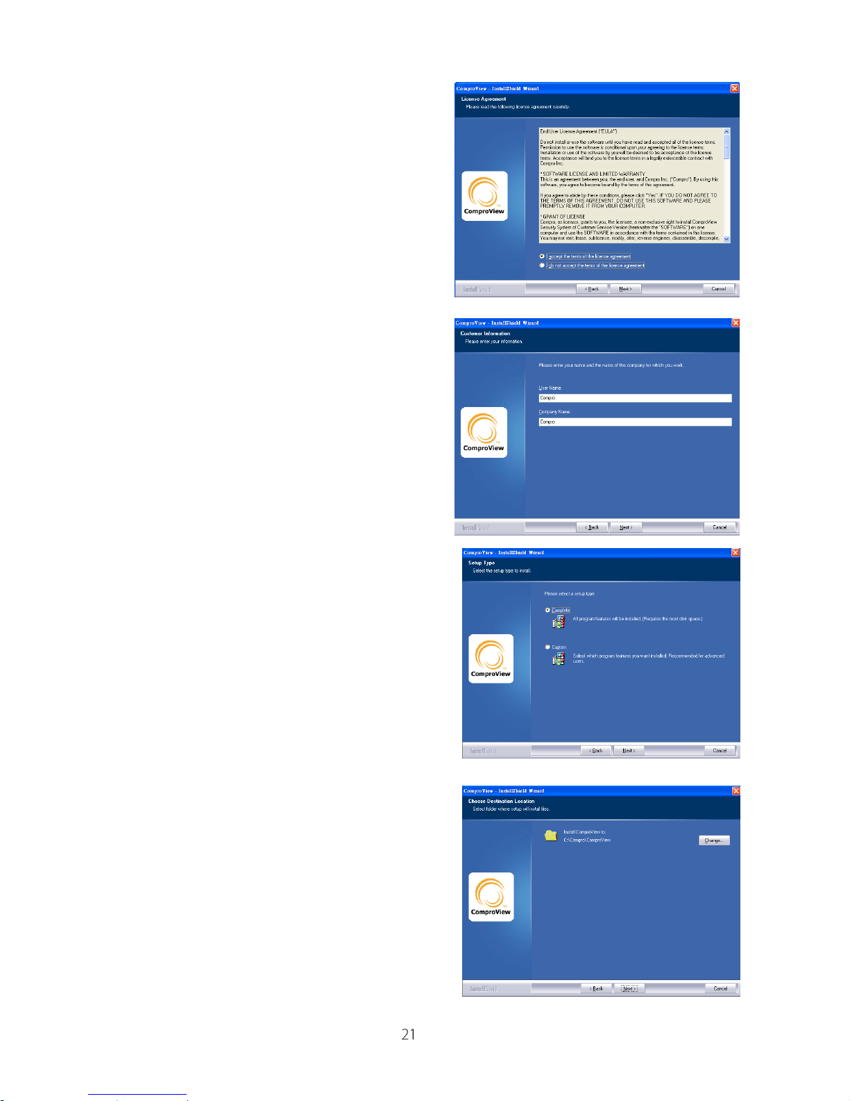
21. Please read the license agreement,
then select “I accept the terms of the
license agreement”, and then press
the “Next” button to continue the
install process.
22. Please enter the user name and the
company name.
23. Depends on user’s demand to choose
the “Complete” or “Custom” selection,
and then press the “Next” button to
continue the install process.
24. If user chooses the “Custom”
selection, user could choose the
specific file folder to install the program.
Page 22
IP540(P) User’s Manual
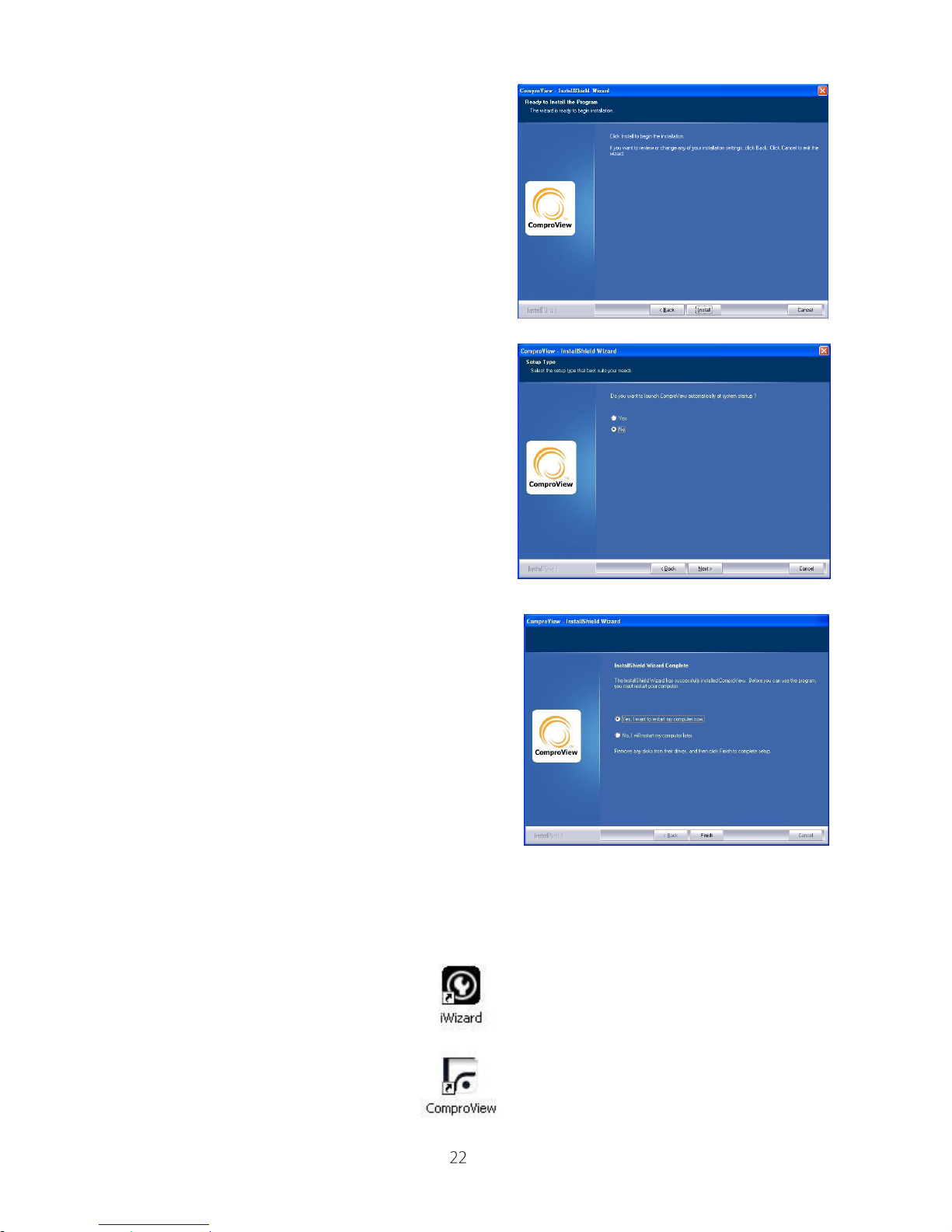
25. After all the setting is ready, please
click the “Install” button to start the
installation.
26. After installation, the program will ask
you want to setup to start the
ComproView when Windows start.
27. After the install process completed, the
ComproView system is finished the
installation. Please click “Yes” to restart
your system.
28. After restart your system, you will see the iWizard and ComproView
icons on your desktop. You can click the “iWizard” to change your camera
setup and click “ComproView” to execute the ComproView program.
Page 23
IP540(P) User’s Manual
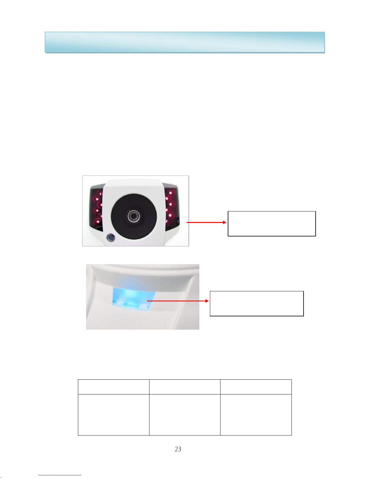
IR Lamps and LED Light of IP540(P) Camera
When you connect the power of IP540(P) camera, the camera will start
booting procedure. The IR lamps and LED light will be lighting as the following
procedure:
1. Once the IP camera Power On after few seconds, the IR lamps and LED
will turn on lighting. The IR Lamps are red.
2. After about 5 seconds, the IR lamps will turn off.
3. Trying to connect: It take about 60 seconds to get connection. After the
connection is established, the blue LED will light on constantly.
4. Connection established: Blue LED lights on constantly.
5. Connection failed: Blue LED lights on with flashing.
LED Status:
Steady (Blue)
Blinking (Red)
Off
Successful
connection to the
network
The camera is
unable to connect
to the network
The unit is either
not working or the
LED had been
turned off.
Power On and Booting
start
Blue: The network
connection well
Page 24
IP540(P) User’s Manual
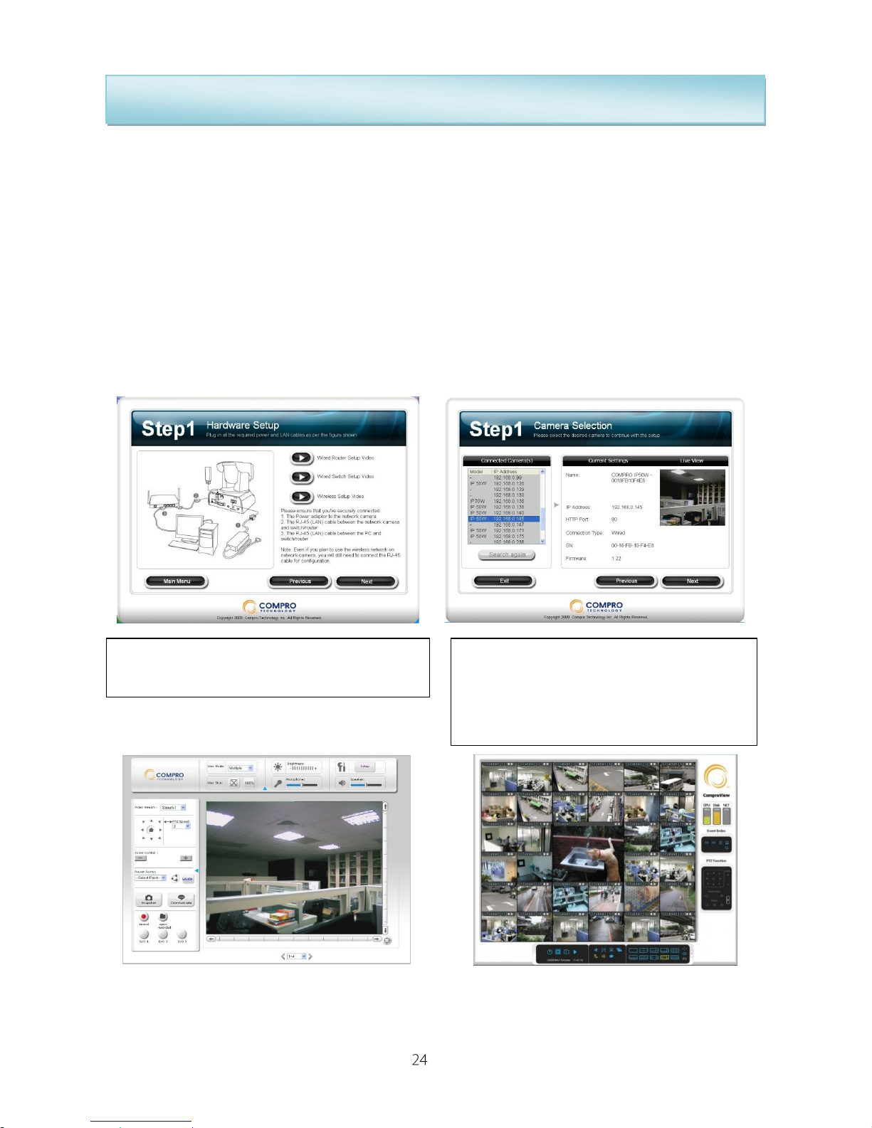
Software for the IP540(P) Camera
The software for IP540(P) camera includes 3 major parts to help you using the
IP camera:
1. iWizard Installer and iWizard utility: Install IP camera
hardware/software and help you to quick setup your IP camera.
2. WebVUer: Live view and controls in Internet Explorer (ActiveX).
3. ComproView: Professional surveillance software.
When you put the installation CD of IP540(P) camera, it will start the iWizard
installer to guide you install the hardware and software of IP camera step by
step.
While running the Installation CD, the Step1
will teach you how to connect the IP camera
After installed the software, when you click
the iWizard icon on your desktop, it will start
to search the available cameras on your
network
WebVUer (Internet Explorer)
ComproView
Page 25
IP540(P) User’s Manual
Access IP camera
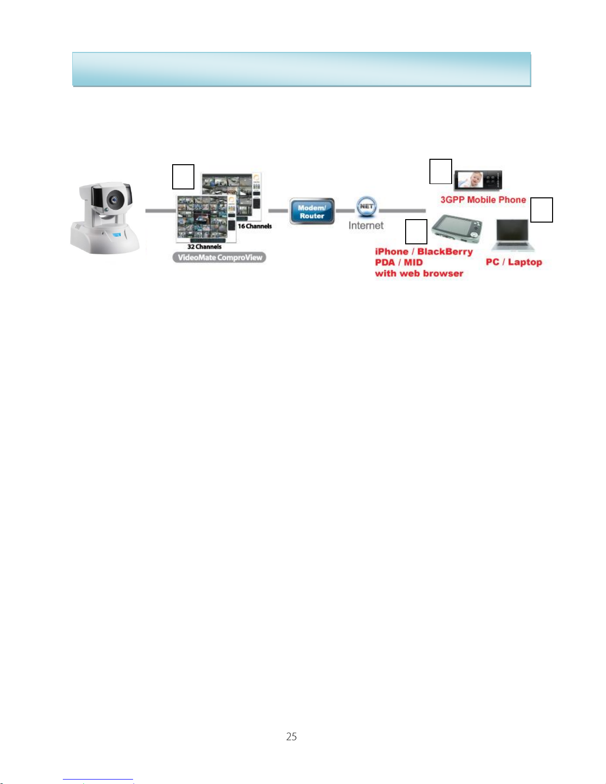
Compro Technology provides a range of access method to access and using
the IP camera that you’ve just installed.
1. Accessing a single camera via the Internet Explorer (WebVUer) which
is found on all Desktop/Laptop/Nettop with Windows system installed.
This is the easiest way of using the IP camera and requires little learning of
the software. (The FireFox browser will be support via firmware update and
VLC plug-in installed)
2. Accessing a single camera via web browser of your iPhone/iPod,
BlackBerry, PDA, MID or other mobile devices with web browser. It
supports Motion-JPEG video watching on your mobile devices in anytime,
anywhere. (Live view only)
3. Accessing a single camera via 3GPP capable phone over the internet.
This is the preferred way of monitoring your camera when you are out of
the house and have no access to a computer. However, due to the
limitation of the technology, only video stream is provided in this mode.
Do keep in mind that your mobile phone network service provider will be
charging a pre-determined rate for using this service.
4. Access a single camera or multiple cameras via the bundled
ComproView software. ComproView is comprehensive software
encompassing the monitoring, recording and detection of the set area. For
the full function of the ComproView, please refer to the electronic manual
included on the CD.
1
3 2 4
Page 26
IP540(P) User’s Manual
Using the IP Camera in WebVUer (Internet Explorer)
User can monitor the current condition of the monitor area via Internet
Explorer which is found on all Windows based machine.
Please refer the following steps:
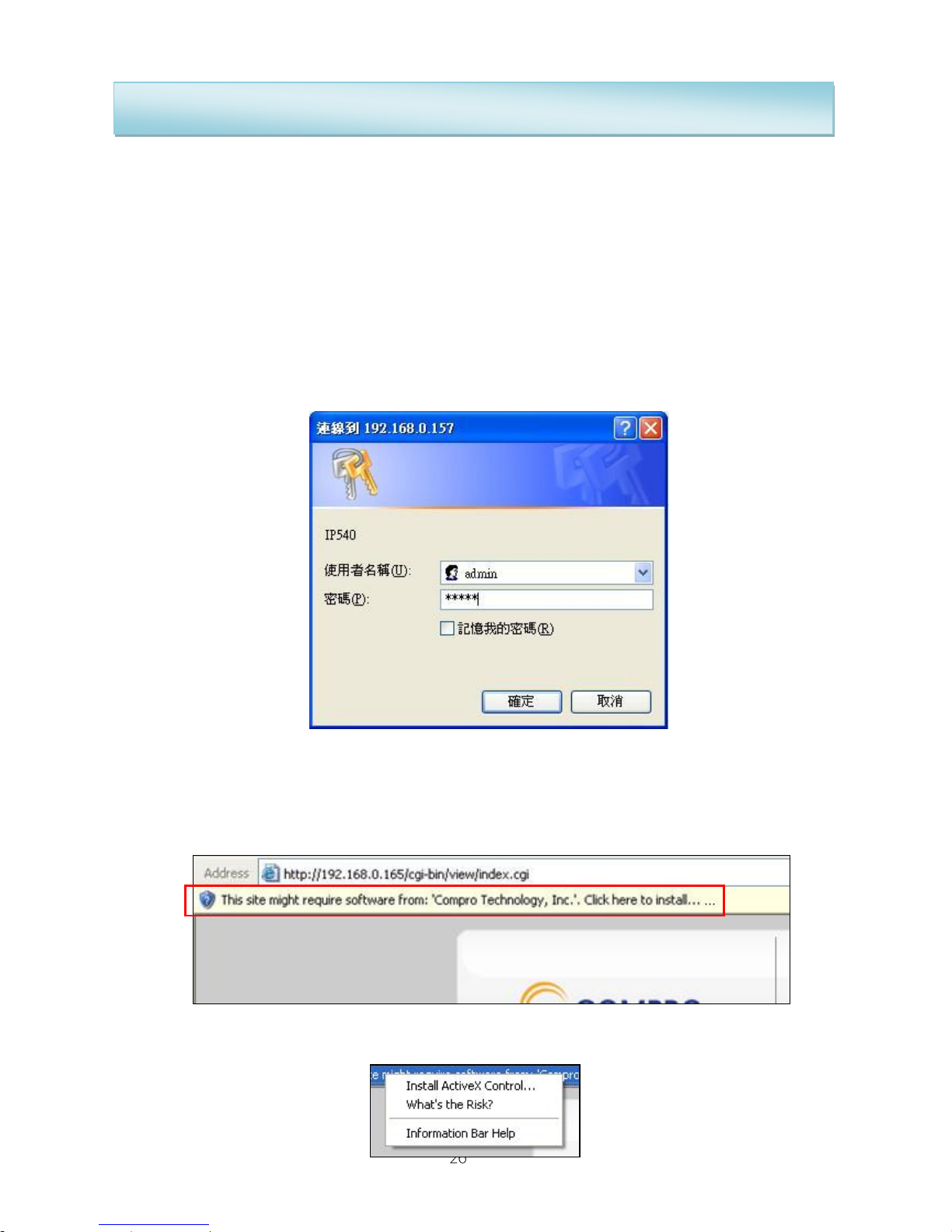
1. Open the Internet Explorer.
2. Enter the camera’s IP address. (192.168.0.x)
3. User will see the dialog to request the user name and password; please
enter the valid username and password of IP camera, and then press OK.
The default user name and password is “admin”.
4. After enter the valid username and password, Internet Explorer will show
up the message to warning user to install the software from “Compro
technology, Inc.”
5. Please press the selection and choose to install the ActiveX
Page 27
IP540(P) User’s Manual
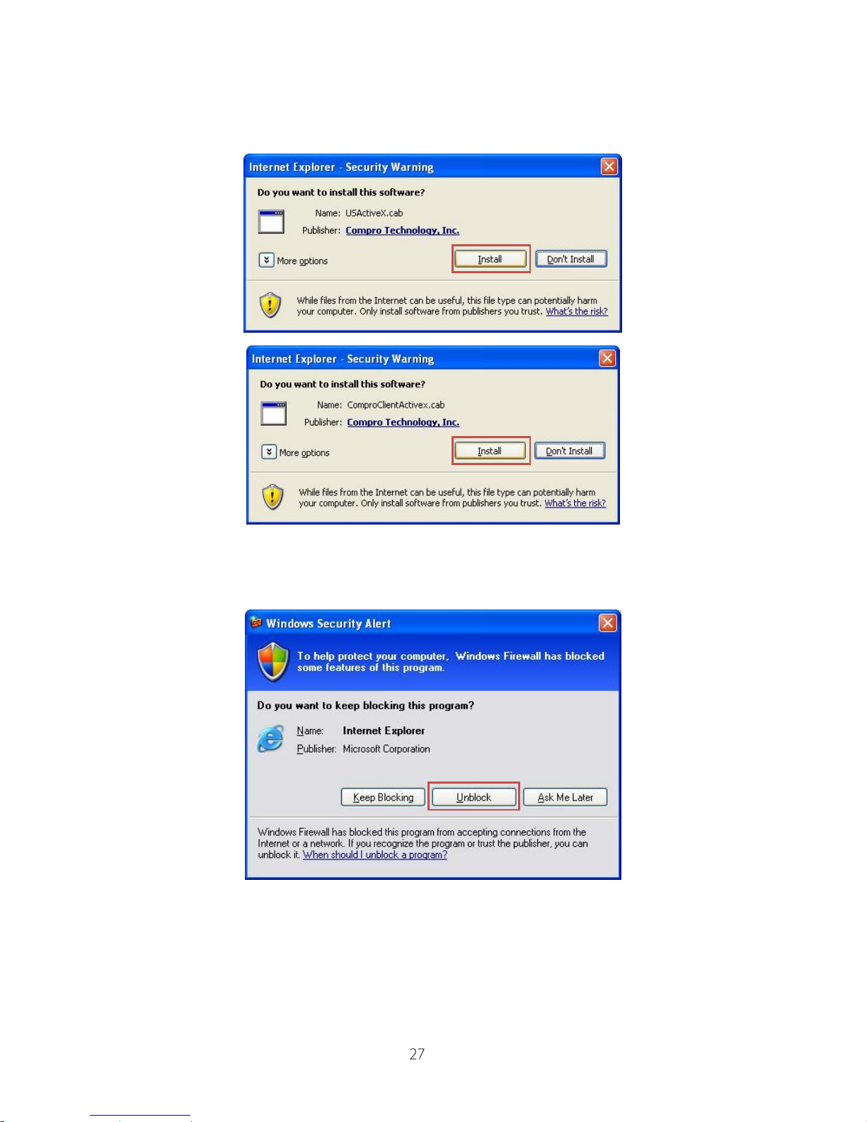
6. And then the reconfirmation dialog will appear on the screen, please press
“Install” button to install the USAtciveX.cab and
ComproClientActivex.cab to your system.
7. After ActiveX install completed, if the Windows Security Alert dialog
appears, please, click “Unblock” to unblock it from firewall.
Page 28
IP540(P) User’s Manual
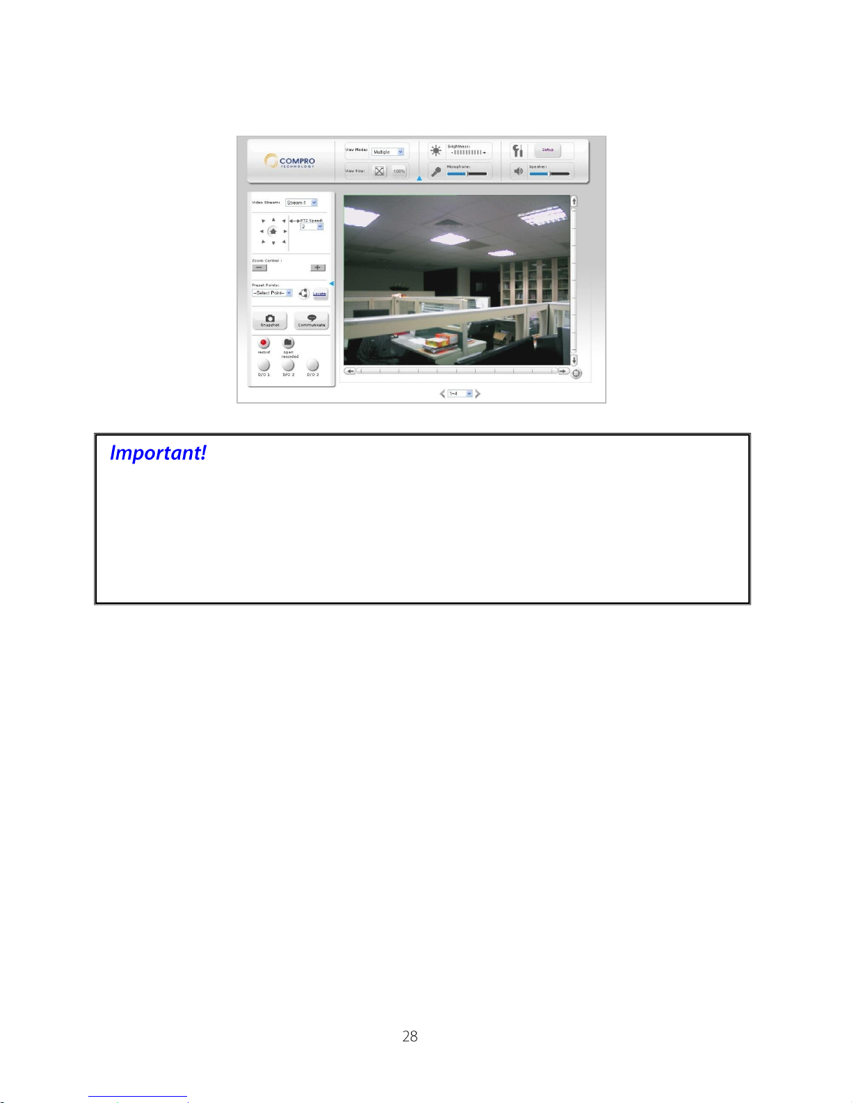
8. Now you can start to use web browser for watch live video and controls IP
camera.
If your IP camera falls behind firewalls, you will need to set port forwarding for
ports 80 and 554 (default value) to the internal IP address of the camera.
Should you have more than one IP camera then please increment the values
of the above ports by 1, e.g. the second camera will have ports 81 and 555,
etc. Please refer to the manual of your router or firewall.
Page 29
IP540(P) User’s Manual
Controls the IP camera in Internet Explorer
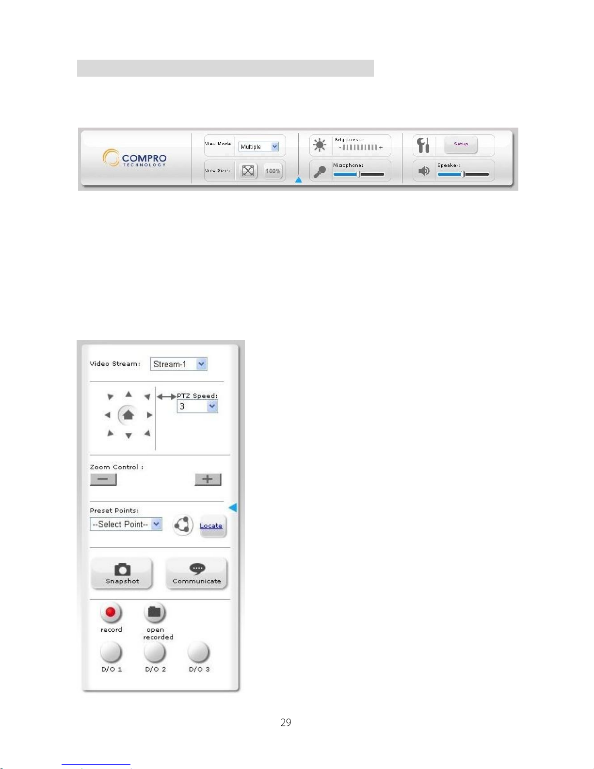
In the first page, you can see the basic control panel in the top and below is
the live video.
Video Mode: Switch between single channel, multiple channels and
auto-scan mode display.
Brightness: Adjust the bright of IP camera as you desire.
Setup: Enter the setup page of IP camera for advanced setup.
Video Size: Switch the video size to fit screen or 100% size.
Microphone: Adjust the volume of audio from microphone.
Speaker: Adjust the volume of audio from speaker.
Video Stream: Switch between
Stream-1 and Stream-2 mode. (Needs to
enable the Stream-2 in video setup
page).
Direction Control: Click the triangle
buttons to rotate the camera as you
desire, and click home to preset home
position.
PTZ Speed: Switch PTZ speed from 1
to 10.
Zoom Control: Zoom the screen for
more detail. (Only available in motion
adaptive mode)
Preset Point: Switch to the preset point
of your camera. (Please setup the preset
points in the Setup PTZ Control)
Patrol Mode: Patrol from preset points
Locate: Locate your camera position on
the screen
Snapshot: Click the button to take
snapshot of live screen.
Page 30
IP540(P) User’s Manual
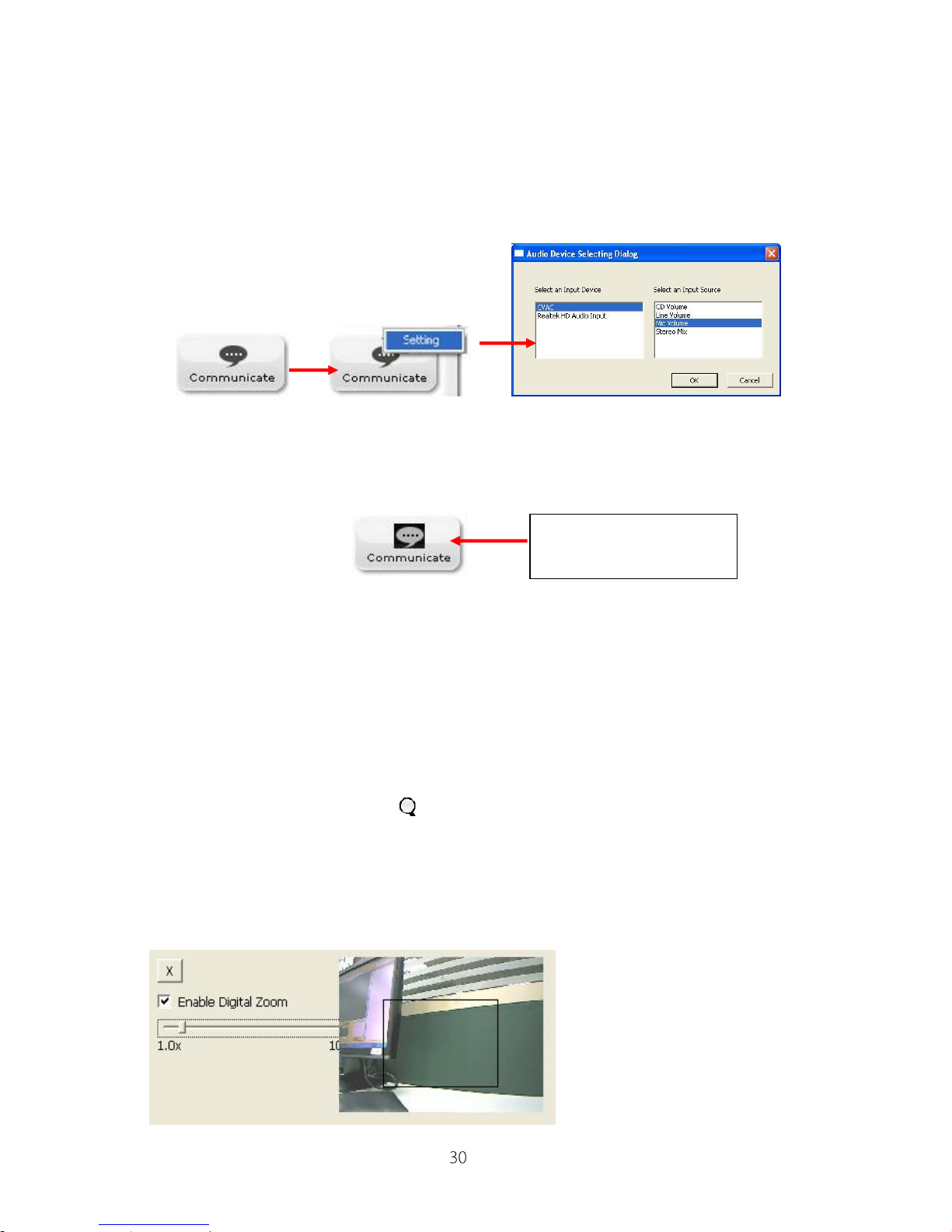
Communicate: This feature will allow you to direct talk from your PC’s
microphone to the IP camera’s speaker. Move the mouse cursor to the
communicate button, it will display the message of “Right click to setup”,
please right-click your mouse and select “Setting” to select Input audio
device.
After setting the audio input device, please click and hold the communicate
button (it will turn to black) to talk to microphone.
Record: Click the “Record” button to take video of live screen.
Open Recorded: Search and play video file was caught by the camera. (File
format is .mkv)
Open Recorded: Search and play video file was caught by the camera. (File
format is .mkv)
10X Digital Zoom: Available zoom factor: 1~10x. To enable the digital zoom
feature:
1. Click on the magnifier icon located on the lower-left corner of real-time
video display, and then the digital zoom control window will pop up.
2. Check [Enable Digital Zoom] option and set desired zoom ratio by dragging
the adjustment bar. Then set the area to be enlarged by dragging the black
square shown on preview window.
Click here and hold
with mouse button
Page 31

IP540(P) User’s Manual
Click on the [X] button shown above or press [Esc] key to save the changes
and/or close the preview window
If your computer can not play .mkv file format, please download and install
VLC media player or KMPlayer from the internet.
Digital Output Control: Control camera to trigger the alarm and siren.
Page 32
IP540(P) User’s Manual
Configuring the IP camera
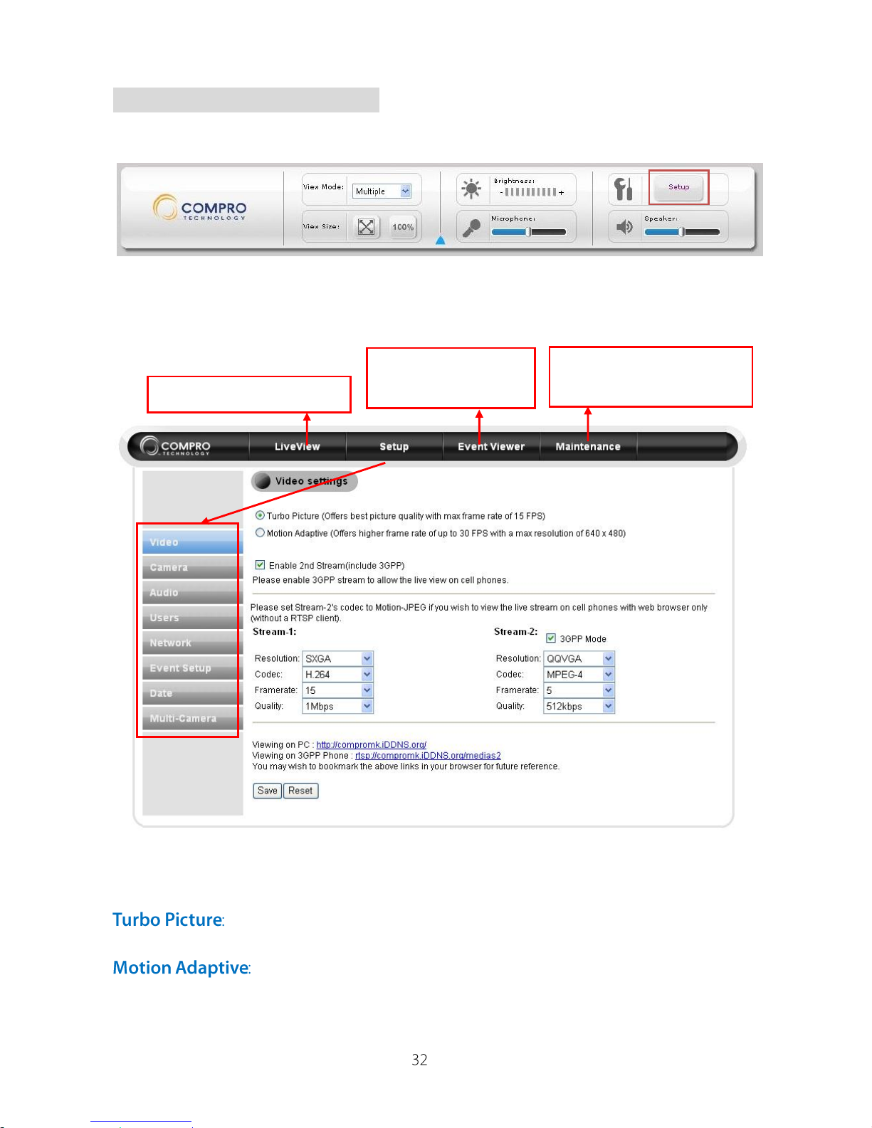
Please click the “Setup” button on the up-right of live view window.
The setup page will as the picture below, you can setup the detail of IP camera
from here:
Video Settings
Select between Turbo Picture and Motion Adaptive mode
This feature will provide you the best video quality, but max
frame rate will limit to 15 fps.
This feature will provide up to 30 fps frame rate with
maximum 640x480 resolutions.
Back to live view window
Information and
maintenance IP camera
Click here to check
event history
Page 33

IP540(P) User’s Manual
If you need to watch the live pictures on your mobile phone or PDA devices.
Please select the “Enable 2nd stream (include 3GPP)” to enable the
Stream-2 video.
Available mode in Stream-1:
Resolution
SXGA (1280x1024)
VGA (640x480)
QVGA (320x240)
QQVGA (160x120)
Codec
MPEG-4, H.264
MPEG-4, H.264
MPEG-4, H.264
MPEG-4, H.264
Frame rate
Turbo Picture
mode: 15, 10, 7.5,
5
Turbo Picture
mode: 15, 10, 7.5,
5
Motion Adaptive
mode: 30, 25, 20,
15, 10, 7.5, 5
Turbo Picture
mode: 15, 10, 7.5,
5
Motion Adaptive
mode: 30, 25, 20,
15, 10, 7.5, 5
Turbo Picture
mode: 15, 10, 7.5,
5
Motion Adaptive
mode: 30, 25, 20,
15, 10, 7.5, 5
Quality
3, 1.5, 1Mbps
3, 1.5, 1Mbps;
512k, 256k,
128kbps
3, 1.5, 1Mbps;
512k, 256k, 128k,
64kbps
3, 1.5, 1Mbps;
512k, 256k, 128k,
64kbps
Available mode in Stream-2:
Resolution
VGA
(Not available in
3GPP mode)
QVGA
QQVGA
Codec
MPEG-4, H.264
Motion-JPEG
MPEG-4, H.264
Motion-JPEG
MPEG-4, H.264
Motion-JPEG
Frame rate
Turbo Picture
mode: 15, 10,
7.5, 5
Motion Adaptive
mode: 30, 25, 20,
15, 10, 7.5, 5
Turbo Picture
mode: 15, 10,
7.5, 5
Motion Adaptive
mode: 30, 25, 20,
15, 10, 7.5, 5
Turbo Picture
mode: 15, 10, 7.5,
5
Motion Adaptive
mode: 30, 25, 20,
15, 10, 7.5, 5
Quality
MPEG-4, H.264:
3, 1.5, 1Mbps,
512k, 256k,
128kbps;
Motion-JPEG:
Highest, Higher,
High, Medium,
Low, Lower,
Lowest
MPEG-4, H.264:
3, 1.5, 1Mbps,
512k, 256k, 128k,
64kbps;
Motion-JPEG:
Highest, Higher,
High, Medium,
Low, Lower,
Lowest
MPEG-4, H.264:
3, 1.5, 1Mbps,
512k, 256k, 128k,
64kbps;
Motion-JPEG:
Highest, Higher,
High, Medium,
Low, Lower,
Lowest
If you have setup the iDDNS service while IP camera installation procedure,
Page 34
IP540(P) User’s Manual
you can direct input the web link of your IP camera and no need to remember
the IP address. (In the case below, the “compromk” is input by yourself in
installation process.)
When network congestion occurs, Compro network camera can intelligently
force down current user-defined video bit rate and bring it back when healthy
bandwidth level becomes available. This avoids video quality deterioration
and frame dropping by restricting network camera to send excessive amount
of data while the network is already overloaded.
In [Setup] > [Video] > [Active bandwidth management], select [Enable] to
activate the function.
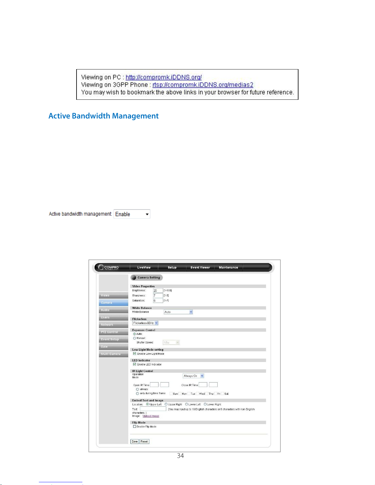
Camera Settings
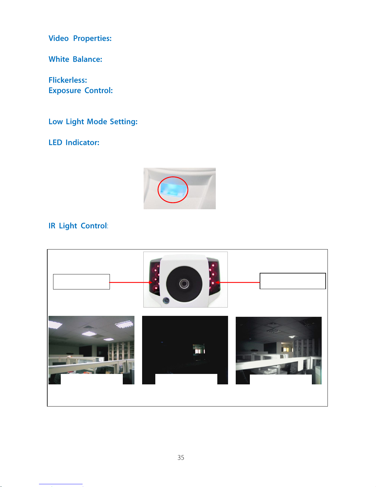
Here you can setup the color and IR light controls of your IP camera.
Page 35
IP540(P) User’s Manual
Adjust the Brightness, Sharpness and Saturation color
controls on your IP camera.
Setup the white balance of IP camera, available selection:
Auto (default), Sunny, Cloudy, Fluorescent Lamp, and Incandescent Lamp.
Setup the flickerless mode in 60 (default) or 50 Hz.
Setup the exposure time of the camera, default in Auto
mode, or you can manual select the shutter speed within 1/5s and 1/16000s to
meet your light conditions.
This feature will enable the camera get better and
clearer picture when the current light is low. (Default is on)
Turn On/Off the LED indicator in case that you do not want
any others notice about the camera is working on.
IP540(P) built-in the IR light sensor and IR LEDs can fit
different light situations and provides the 24-hours, 7-days monitoring.
IR Light Sensor
IR Lamps (Inside)
Normal light
(Indoor Light on)
Without IR lamp
(Indoor Light off)
With IR lamp
(Indoor Light off)
Page 36
IP540(P) User’s Manual
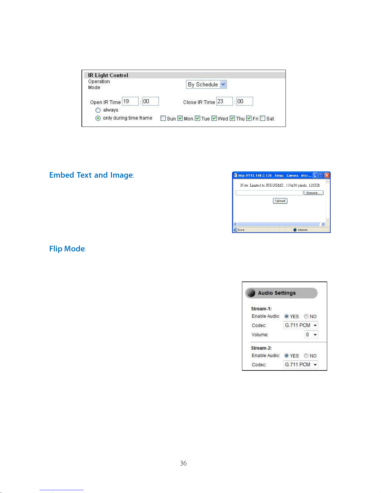
The IR light sensor can detect the indoor light condition and turn on/off the IR
lamps; you can setup the IR light operation mode in Auto, Always On, Always
Off, or By Schedule.
For schedule on/off the IR sensor and lamps, you can directly input the open
and close time you desired, and select always on or during special week days.
(In this case, it will turn on the IR sensor and lamps in 19:00 to 23:00 from
Monday to Friday.)
This feature allows you
to embed text on the live screen, and with 4
locations to be chosen and displayed. (Upper
Left, Upper Right, Lower Left, Lower Right)
Then please click the “Upload Image” link and
choose the suitable image. (Limited to
JPEG/BMP, 100x30 pixels, 128KB)
Setup your camera according to standard position or ceiling
mount.
Audio Settings
Here you can setup to enable or disable the audio
and also adjust the volume up and down.
The Stream-2 audio is available when you turn on
the Stream-2 feature in video settings and support
the 3GPP mode only.
Page 37
IP540(P) User’s Manual
Users Settings
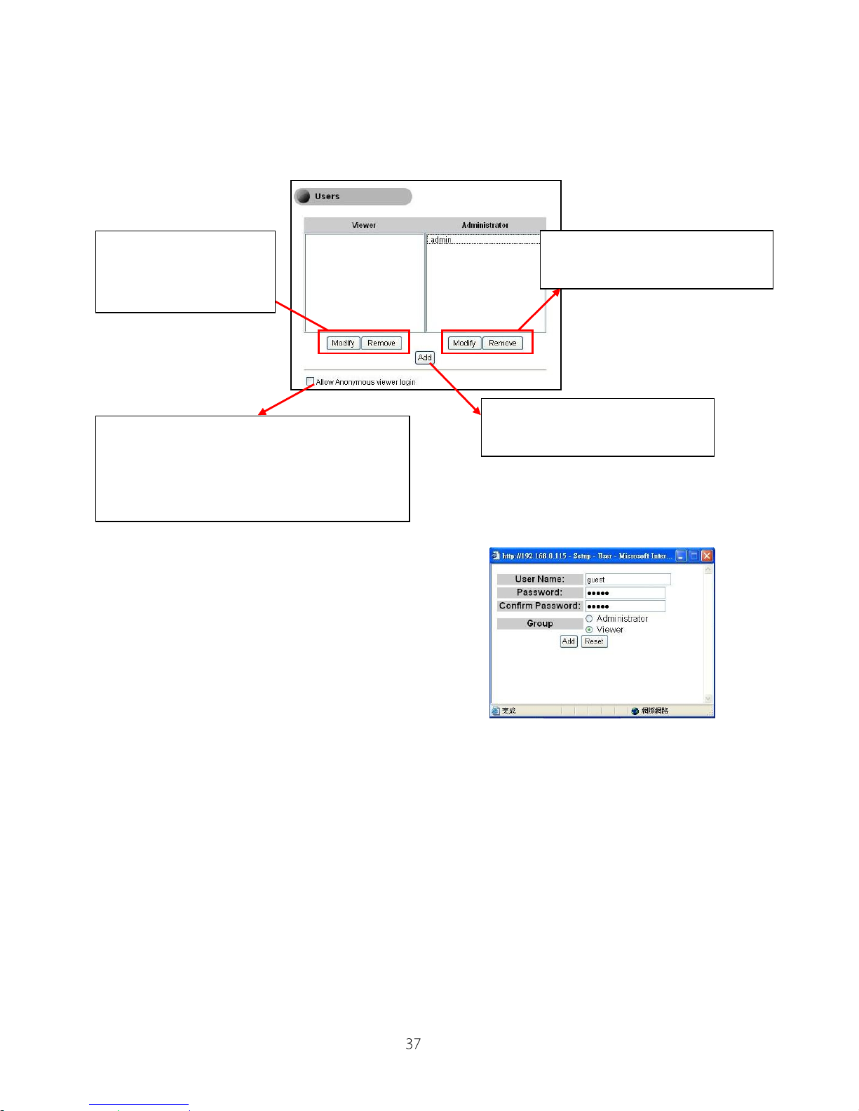
Here you can create, modify and remove viewers/administrators. The viewers
only allow watching live video but can’t change any settings of camera.
When you add new users, you need to input
the username, password and group type.
Click here to Modify or
Remove current
viewer
Click here to Modify or
Remove current administrator
Click here to add new viewer
or administrator
Click here to allow anonymous viewer
login without username and password
required, but only allows previewing the
live video
Page 38
IP540(P) User’s Manual
Network Settings
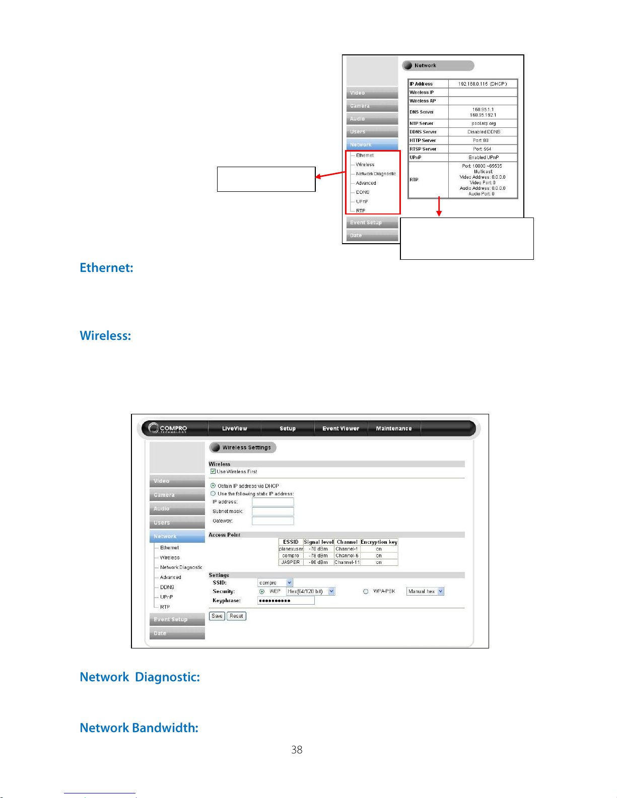
Here you can check your network settings
and do the detail settings.
Setup the IP address of IP camera from DHCP mode
(recommended) or input the static IP address. And also input the username
and password of the PPPoE network.
If you have installed the Compro wireless adaptor in your IP
camera, you can setup the wireless in this page. Please click the “Use
Wireless First” to enable the wireless reception in the future. And then setup
the IP address and the access point details. Then, please click “Save” to take
it effect.
Here you can run the diagnostic tool for your current
network settings and it will show the information if any error. If there is any
error display, please refer to the FAQ section for more information.
This automatic network connection speed detection is to
Current network
settings overview
Detail setting list
Page 39
IP540(P) User’s Manual
help users better define appropriate video bit rates for their applications.
1. In [Setup] > [Network], click on [Network Bandwidth] located on the left
menu to start.
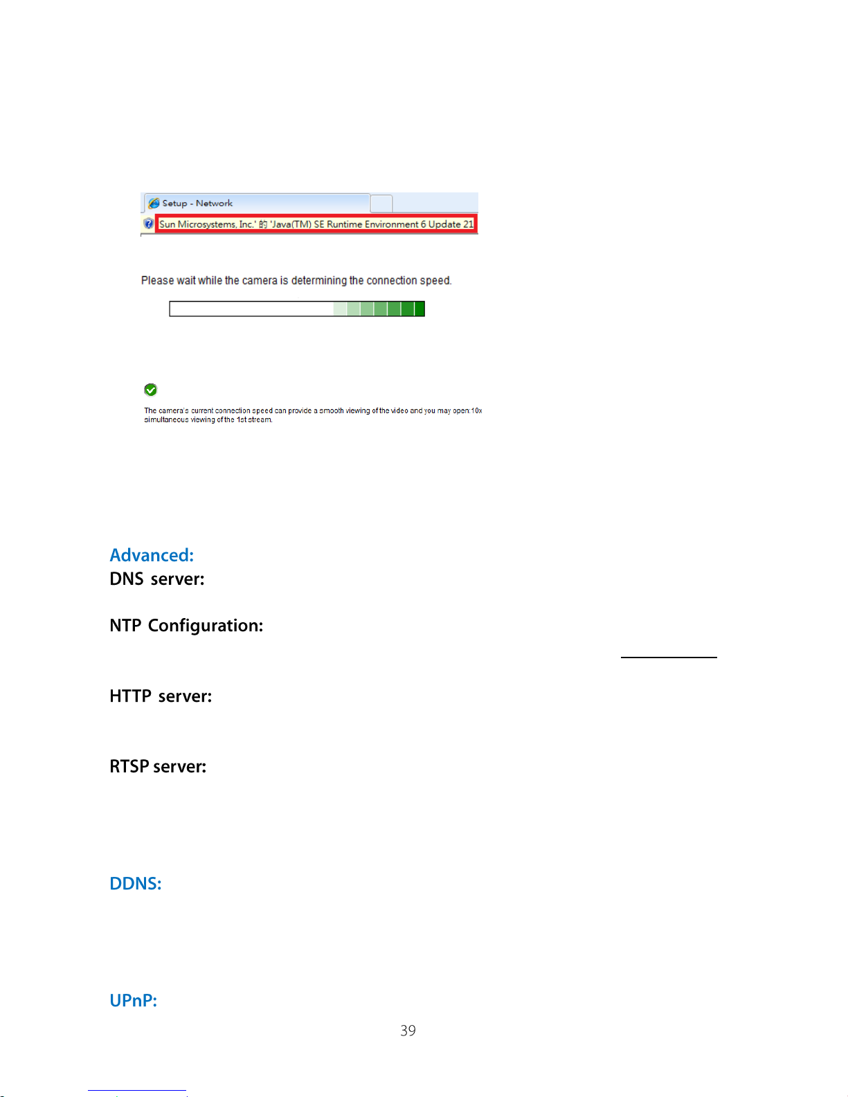
2. Wait for Internet Explorer to prompt for the installation of Java plug-in.
Then click on the text to accept.
3. Camera begins detecting connection speed.
4. Once speed diagnostics is done, camera will advise an ideal value for this
particular user environment. See below example:
The message indicates that currently connected network has a bandwidth
to support up to 10 network cameras of identical bit rate settings (either on
Stream 1 or Stream 2). If the message shows a less favorable result, go to
[Setup] > [Video] to lower current video bit rate values
Setup the DNS server address via DHCP or given DNS server
name.
Setup the NTP (Network Time Protocol) server address
to makes the time on IP camera is correct. The default will use pool.ntp.org to
check the time correction.
Setup the HTTP port for your IP camera to watch and control
the IP camera from internet. (Default: 80) If you need to use the port
forwarding, please refer the FAQ section for port forwarding setup.
Setup the RTSP (Real-Time Streaming Protocol) port for your IP
camera to support 3GPP stream on the mobile phone. (Default: 554) If you
need to use the port forwarding, please refer the FAQ section for port
forwarding setup.
Click here to enables the DDNS (Dynamic Domain Name Service)
service, recommended to use the Compro iDDNS service. Or if you already
have the account from DynDNS or no-ip, you can input the domain name in
here for more easily to access your IP camera.
Click here to enable/disable the UPnP settings of IP camera in your
Page 40
IP540(P) User’s Manual
local network. Also, you can change the device name by yourself. If you want
to use the IGD (Internet Gateway Device) protocol on your IP camera, please
click and enable it.
If you want to setup the broadcast of video with RTP (Real-time Transport
Protocol), you can setup the port range, video/audio address and port number
in here.
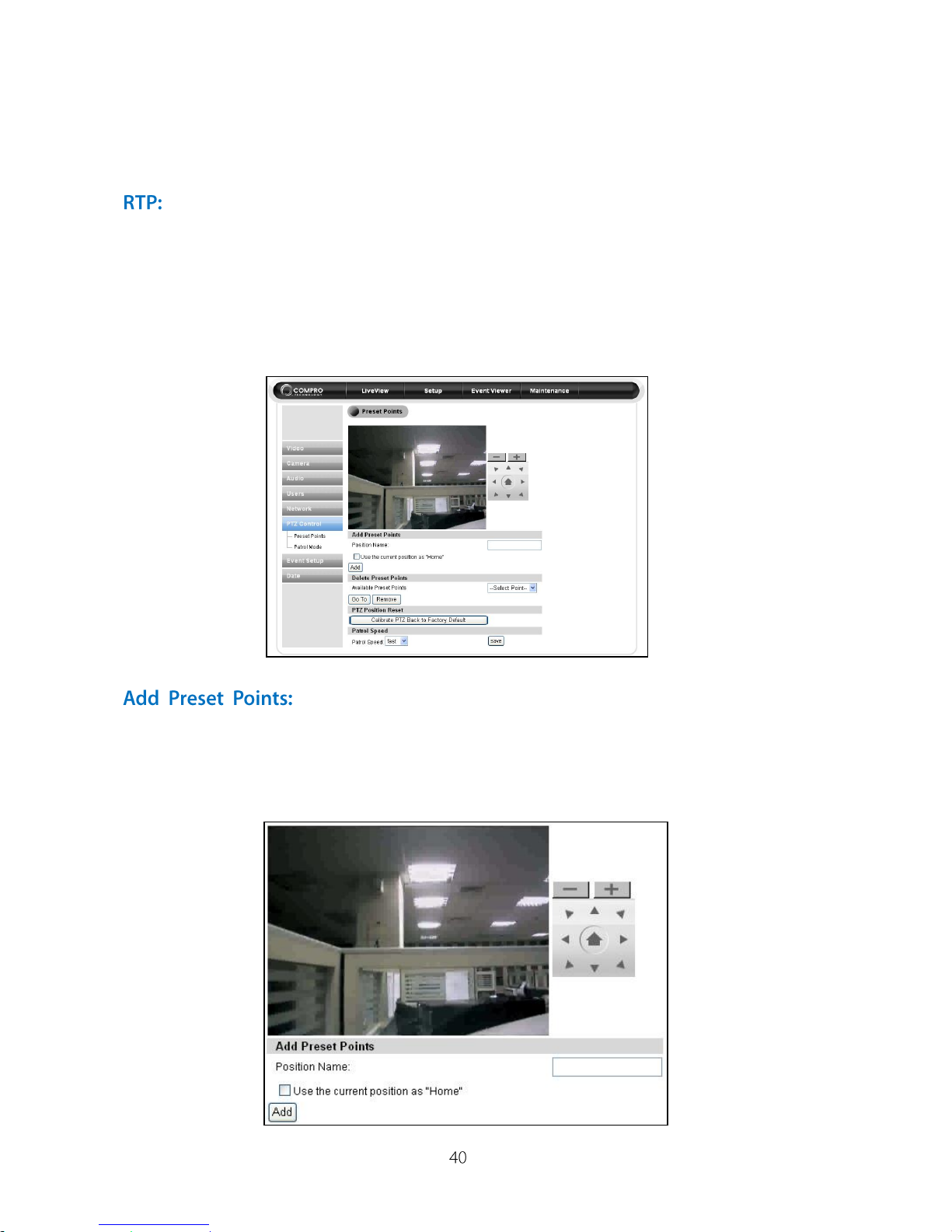
PTZ Control
Here you can add preset surveillance points. The IP camera will patrol the
preset areas.
Firstly use direction tool to move the IP camera to the
desired position. And then type the position name for the surveillance position.
After the settings, please click “Add” to activate. If you would like to use the
position as initial point, please click “Use the current position as “Home””
button.
Page 41
IP540(P) User’s Manual
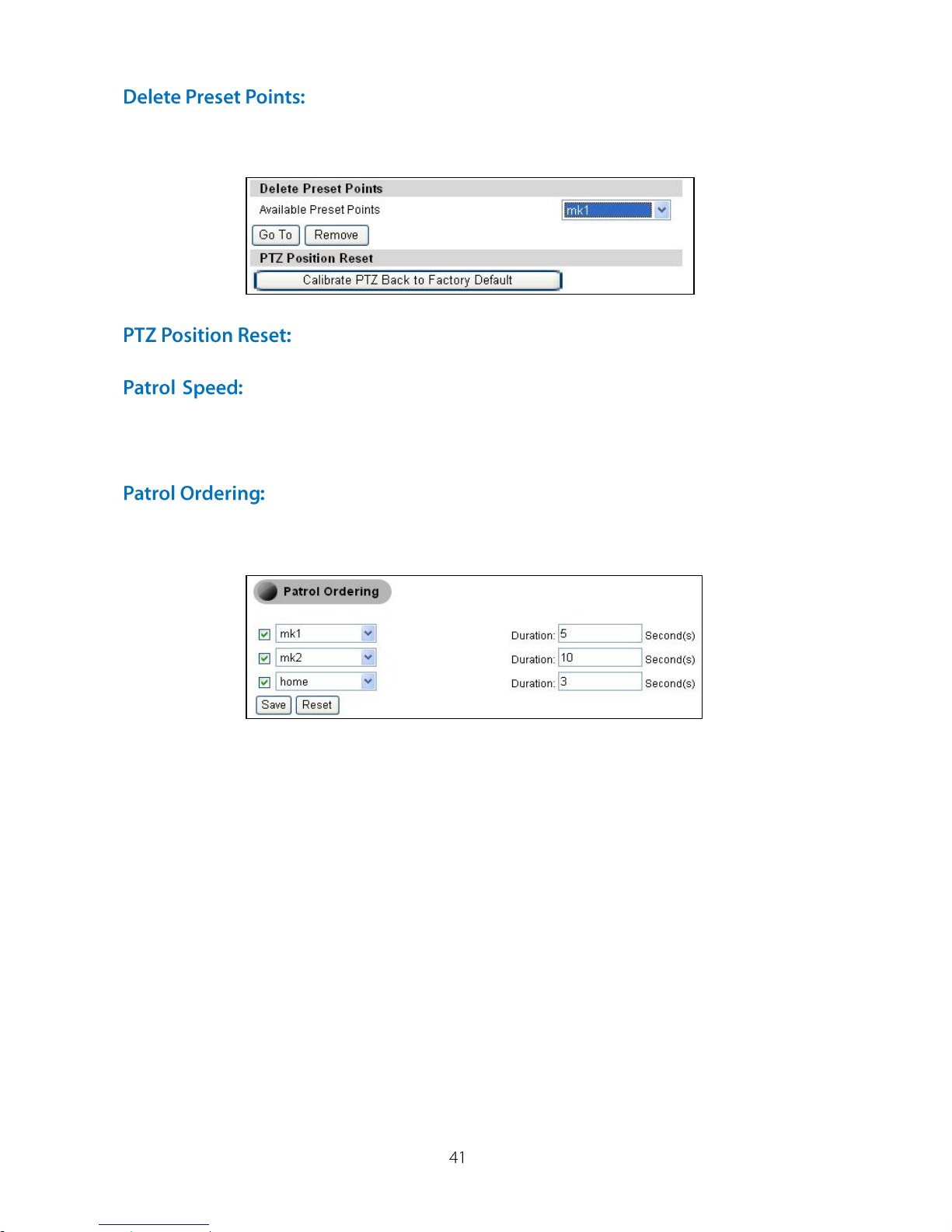
If you would like to delete the preset point, please select
the specified point. Before you click “remove” to delete the preset point, please
click “Go To” button to confirm the surveillance point with image.
Click here to calibrate PTZ back to factory default setting.
Here you can set up the IP camera patrol speed with fast and
slow mode. After you have chosen, please click “Save” button.
Once you add preset points, you could setup the duration for
specified point. Just simply select one of preset points, and then input the time
of duration. After the settings, please click “Save” to take it effect.
Event Setup
When event happened, like motion detection or I/O triggers by detection, the
snapshot will instantly send to your mail, ftp, image or ComproView notify
server to warning you about what’s happened.
In order to properly setup the event function, the users must:
1. First setup the event server based on the need, E-mail, FTP, Image or
ComproView Notification.
2. Once the even server are setup, the user can now go to the trigger setup
to setup the type of events, motion, schedule and the associated even
actions.
3. In the motion detection page, the users can setup the region and the
sensitivity of the detection.
4. If the users want to use the I/O input, please connect the I/O devices
before event setup.
Page 42
IP540(P) User’s Manual
Here provides the 4 different event server configurations
in E-mail, FTP, Image or ComproView Notify server. Please click and select
the way of event server you need and input related server information.
Support of standard SMTP on SSL-protected webmail
platforms such as Hotmail (Windows Live) and Google Mail (Gmail) is also
included. To use this function, in [Event Server Setup] > [Email Event Server
Setup], enter their SMTP address and SSL port respectively. Then enter your
user name and password, and the E-mail subject as you wish.
As of August 2010, SMTP and SSL settings for Hotmail and Gmail are as
follows:
SMTP
SSL
Hotmail
smtp.live.com
587
Google Mail
smtp.gmail.com
465
In [Authentication Method], select [Login]. Enter a complete email address in
[User Name] field: [email protected]. Other SSL webmail platforms are not
tested.
Here provides the configuration for SMS notification feature that
allows the camera to send a SMS (Short Message Service) alert message to a
user-specified recipient when a pre-defined event scenario is being triggered.
This feature does not require additional hardware GPRS modem and SIM
card installed. Users only need to first apply an account with a third-party,
web-based SMS gateway service provider. To properly configure SMS server:
1. Under [Setup] > [Event Setup] > [Event Server Setup], click on [SMS server]
to start configuration.
2. Provide the required data for the following field:
Service provider
User name
API ID
Target country
Target cell phone
Default: Clickatell
User name registered at Clickatell
API ID provided by Clicktatell
The country code for recipient’s mobile phone number
Recipient’s mobile phone number
If you do not have a Clickatell account yet, please visit [www.clickatell.com],
and under [Login] > [New Customer] > [Product Selection], choose [Clicktall
Central (API)] and proceed to obtain an API ID according to its online
instructions.
Page 43
IP540(P) User’s Manual
3. Choose [Next] to save the setting.
4. Customize the SMS message content if wanted. Choose [Next].
5. To receive a test message, click on [Send me a SMS message to the SMS
Gateway]. Or choose [Finish] to save the configuration.
6. To enable SMS notification, go to [Setup] > [Event Setup], and click on
[Trigger Setup] to create a new event trigger or modify an existing one.
Then under [Event Actions], check [Send SMS] and choose [Finish].
Note: You must have enough credit at Clickatell in order to send SMS message.
You can create, modify, or delete event trigger by Schedule,
Motion Detection or I/O ports. In the schedule setup, you can setup schedule
time and period. Or select the trigger area in preset Motion Detection areas.
Also select the I/O port for trigger. After select the trigger type, please click
“Next” to select event actions to take snapshot, e-mail, upload image to ftp or
warning to output port.
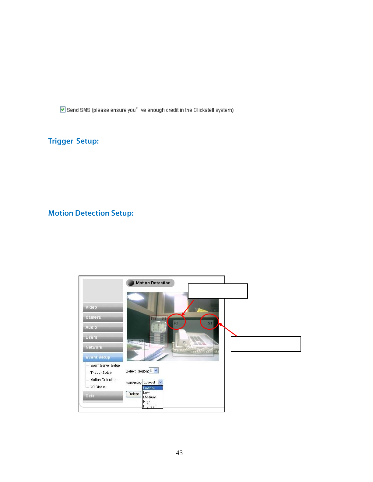
Motion detection feature provides 3 regions selection for motion detection.
You can directly use the mouse to select the region on the preview screen.
Please select the region 0, 1 or 2 first, then select the sensitivity level (S1:
Lowest, S2: Low, S3: Medium, S4: High, S5: Highest), and select the motion
detection region on preview screen with your mouse cursor.
If you do not want the preset region, please select the region number and click
“Delete” to delete it.
Region Number
Sensitivity Level
Page 44
IP540(P) User’s Manual
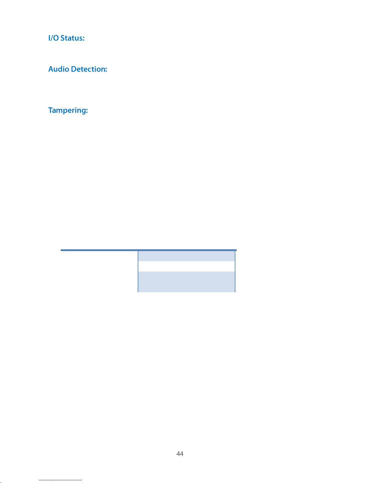
Here will display your input devices status for your reference.
Here you can setup the audio detection sensitivity level in Low, Medium, High
for event trigger.
Here you can setup the tampering sensitivity level in Low, Medium, High for
event trigger.
Recording Setup
In addition to the capability of storing event snapshots to local SD Card slot
(card not included), this camera also supports storage of video clips (audio
may be included if enabled) to either the local or the remote storage device. To
access this feature, in [Setup], click on [Recording Setup] located on the left
menu. In order to properly access the recording function, the users must
consider:
1. Destination: One of the following storage media may be selected.
Local
Remote
microSD/SDHC
V
NAS (Samba-based)
V
NFS (Network File
Server)
V
2. microSD/SDHC Setup:
SD Card Status
Status verification
SD Card Capacity
Show available and total space in the card
Format
Show available and total space in the card
Enable Recording during
network failure
Click to allow forced recording to SD card during
network failure
3. NAS Setup:
Domain Name / IP Address
Network address of Samba-based NAS(Network
Attached Storage)
Directory
Storage path
User Name / Password
User authentication data set for NAS
Check NAS Status
Status verification
Page 45
IP540(P) User’s Manual
4. NFS Setup:
IP Address
Network address of NFS (Network File Server)
Directory
Storage path
5. File Management: Once the selected storage is full, the oldest file will
automatically be overridden.
6. Recording Setup: Click on [Next] to setup recording methods:
Event-based or Scheduled.
Event-based Recording: Records when motion, audio and I/O are
triggered (multiple choices). Recording length: 60~3,600 sec, default 60
sec.
Schedule Recording: Allows non-stop recording for selected weekday(s)
and start/end time.
Disable Recording: Turns off recording function.
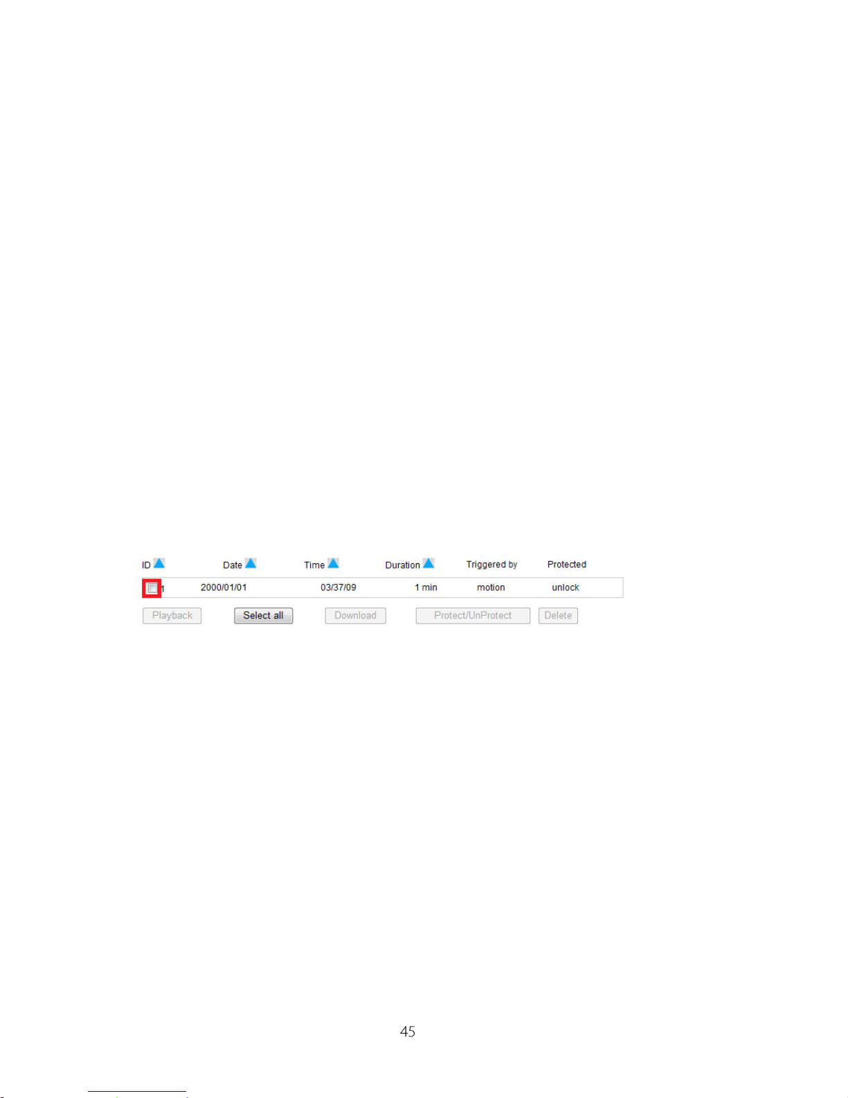
7. Playback: In [Setup], click on [Recording History] located on the left menu,
then playback menu will be shown as follow:
To playback, first select a video clip on the list (red square shown above).
File format: AVI.
Date Setup
Here display the current time setting in your IP camera, and you can setup the
Time Zone with your current region or country, get time from NTP server, sync
you’re your local PC or manually adjust it.
Playback
Download
Protect/Unprotect
Select All / Deselect / Delete
Click to download then playback
Click to download
Selected clip(s) will never be erased
File management
Page 46
IP540(P) User’s Manual
Multi-Camera
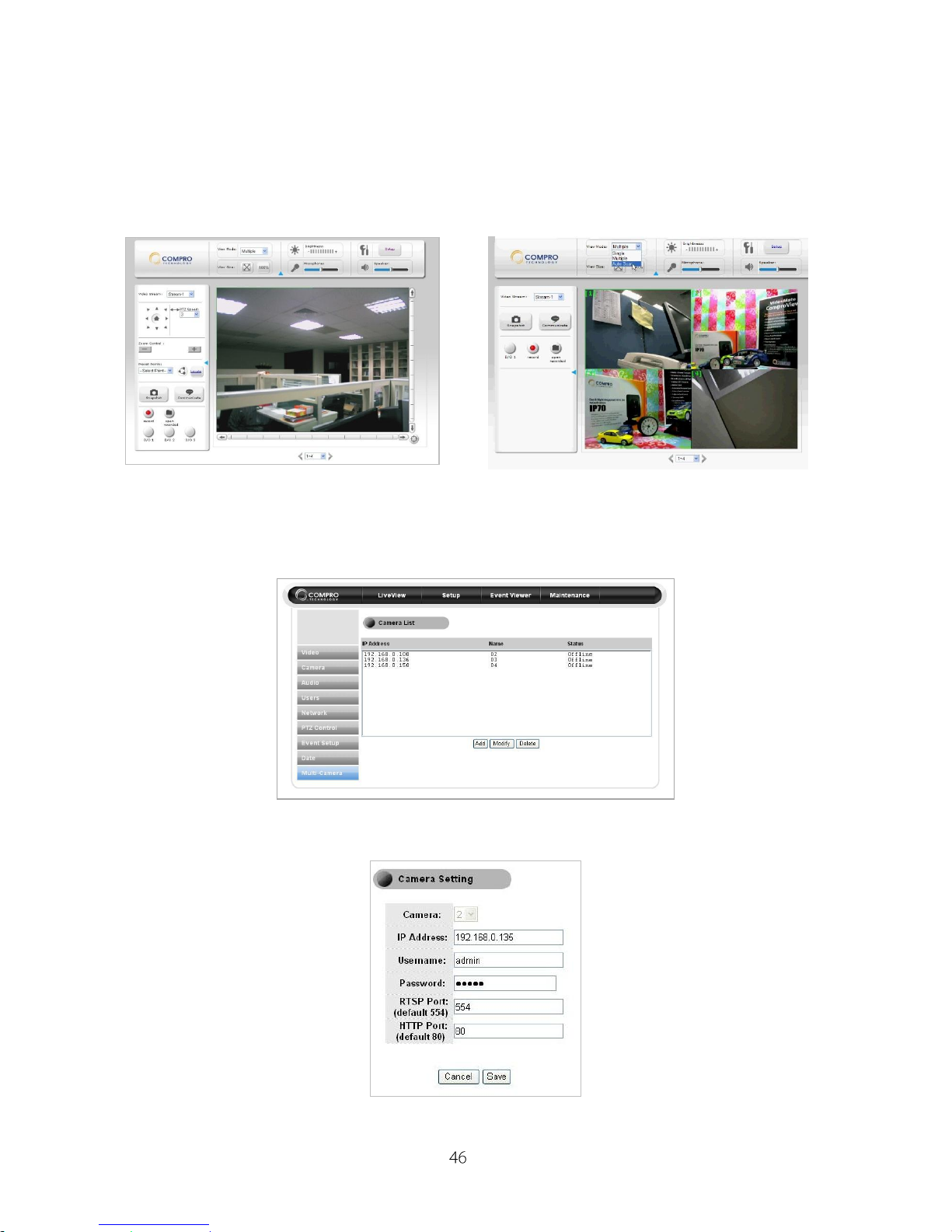
IP540(P) support multiple camera display and control, you can setup and
manage the camera in here. Here display the current time setting in your IP
camera, and you can setup the Time Zone with your current region or country,
get time from NTP server, sync you’re your local PC or manually adjust it.
As the picture below, you can see the entire camera list. Also, you can click
the “Add” button to add camera on the list, or modify/delete current cameras.
When you add and modify camera, please input the IP address, Username,
Password, RTSP port number and HTTP port number for setup.
Single camera mode
Multiple cameras mode
Page 47
IP540(P) User’s Manual
Event Viewer
Here display the current time setting in your IP camera, and you can setup the
Time Zone with your current region or country, get time from NTP server, sync
you’re your local PC or manually adjust it.
Maintenance
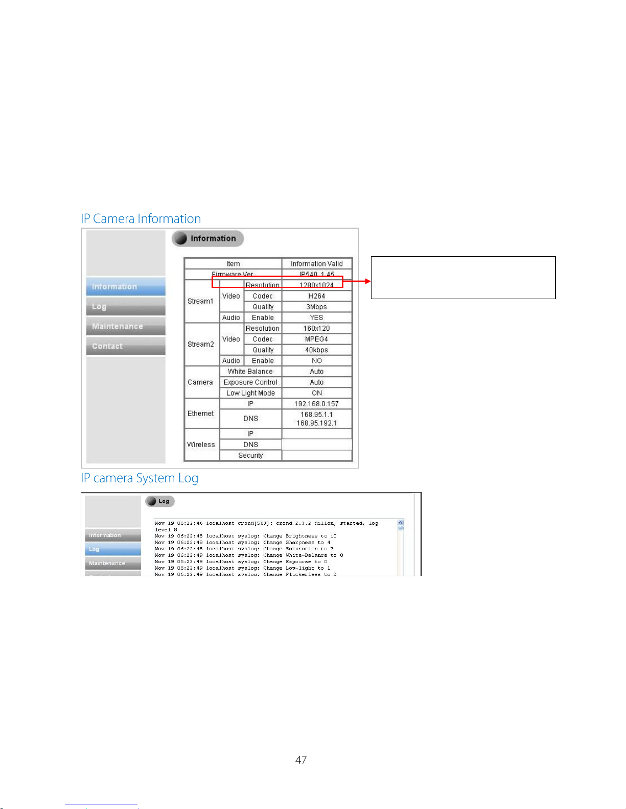
Here provides the current information about your IP camera, history log,
Compro contact information and maintenance your IP camera.
Here you can check the firmware
version of your IP camera
Page 48
IP540(P) User’s Manual
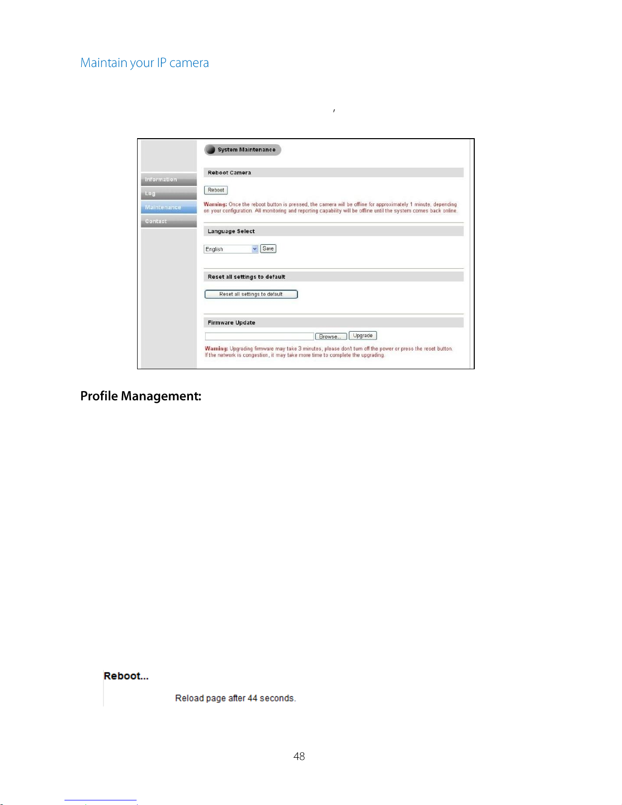
You can reboot your IP camera, select available language, manage user
profile, reset to factory default, or update the firmware of IP camera (Please
download the latest firmware from Compros website).
The profile management feature allows installers and users to set up more
than one camera of similar configurations at great ease. After the current
camera is properly configured, users can export current configurations to a
profile on PC then import it into other cameras, thus making least changes
possible like changes on IP address or a few other settings that might need to
be modified individually. In addition, this feature can also be considered as a
backup mechanism for future service need.
1. After the current camera is properly configured, go to [Maintenance] >
[Profile Management], and click on [Export] to download camera profile to
a user-defined location.
2. To apply configurations to other cameras, press [Browse…] and select the
right file you wish to upload, and then click on [Import] to proceed.
3. Camera will start to reboot, which will take approximately 60 seconds to
complete. User must not interrupt browser action during the process as
doing so may cause problems to the system.
Note that you may only cross-import profile among identical camera
models.
Page 49
IP540(P) User’s Manual
Access the IP Camera via iPhone/mobile device
Compro provides web browser support via MJPEG mode (video only) on
wide range of PC, NB, Mobil Phone, PDA, Nettop, MID devices to view the IP
camera video anytime, anywhere and anyplace.
The supported browsers are listed as follows:
Windows: IE, Google Chrome, Safari, FireFox
Linux: FireFox
Mobile Device: iPhone, iPod Touch, BlackBerry, Android, WM and Major
Brand Mobiles.
Please follow the steps below to watch the video on your mobile device:
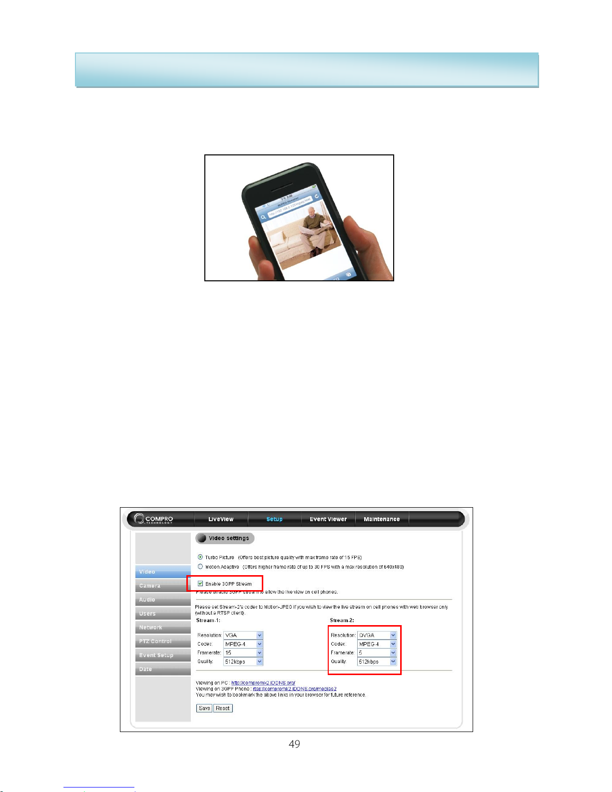
Step1: Please go to the Setup Video Settings page of your IP camera,
and click the “Enable 3GPP Stream” to enable the stream-2 video.
Step2: In the Stream-2, setup the Codec to “Motion-JPEG”.
Step3: Enter IP-address/mjpeg.html into the phone's web browser to watch
video on your mobile device.
Page 50

IP540(P) User’s Manual
Access the IP Camera via 3GPP Mobile Phone
You can access the desired IP camera via compatible 3GPP mobile phone
when both the IP camera has a working internet connection and the mobile
phone has a good connection on the GPRS or 3G network.
There are several criteria which need to be fulfilled before the 3GPP function
can be successfully utilized.
1. In order to use the 3GPP function, you should turn on the 2nd stream of the
IP camera and set the resolution as QQVGA, FPS as 5, and quality as
medium. In addition, by enabling the 2nd stream, you will notice a drop in
the frame rate in the primary stream. This is a normal behavior since the
hardware has to process two streams instead of just one.
2. Please apply for a Dynamic DNS (DDNS) address as specified on the
previous page.
3. Please ensure that you’ve got an active internet connection on both the IP
camera and the intended mobile phone.
4. To view the live image, please enter the following address into the phone’s
web browser or streaming software, “rtsp://ipcamera-ip/medias2”.
The ipcamera-ip is the DDNS address that you’ve obtained in the
installation.
Compatible Phones:
HTC: Touch Diamond
Nokia: N78
Samsung: U708
Sony Ericssion: K610i / W850i
Incompatible Phones:
Nokia: 6500C
Sony Ericssion: T700 / W910 / Z750i
Dopod: CHT9110
Page 51
IP540(P) User’s Manual
The Internet Setting
The IP camera connection could follow the method below:
1. If user’s PC is support Universal Plug and Play (UPnP™) service and
network setting is in DHCP, the Compro IP540(P) will auto detected and
add it into the My Network place.
(If user could see the Compro IP540(P) already, please switch to next page)
Note: If user wants to install the UPnP™ service, please execute the
“Add/Remove” program in “Control Panel”. After the dialog opened,
please select “Add/Remove Windows Components” and select the
“Networking Services” selection. User will see the “Detail” button, please
press it and try to find the “UPnP” selection. Please select it and add it into
user’s operation system.
2. If user uses the router, user should easy to see the IP address had been
assigned for the Compro IP540(P) in the router’s administration pages. If
user gets any problem, please refer the router’s documentation.
3. If user uses DHCP to connect to internet, then user needs to apply for a
DDNS (Dynamic DNS), user could apply to a new hostname from Compro’s
free iDDNS service or refer to the DynDNS or no-ip website and apply for a
new one. After user gets the DDNS, please enter the IP address to login the
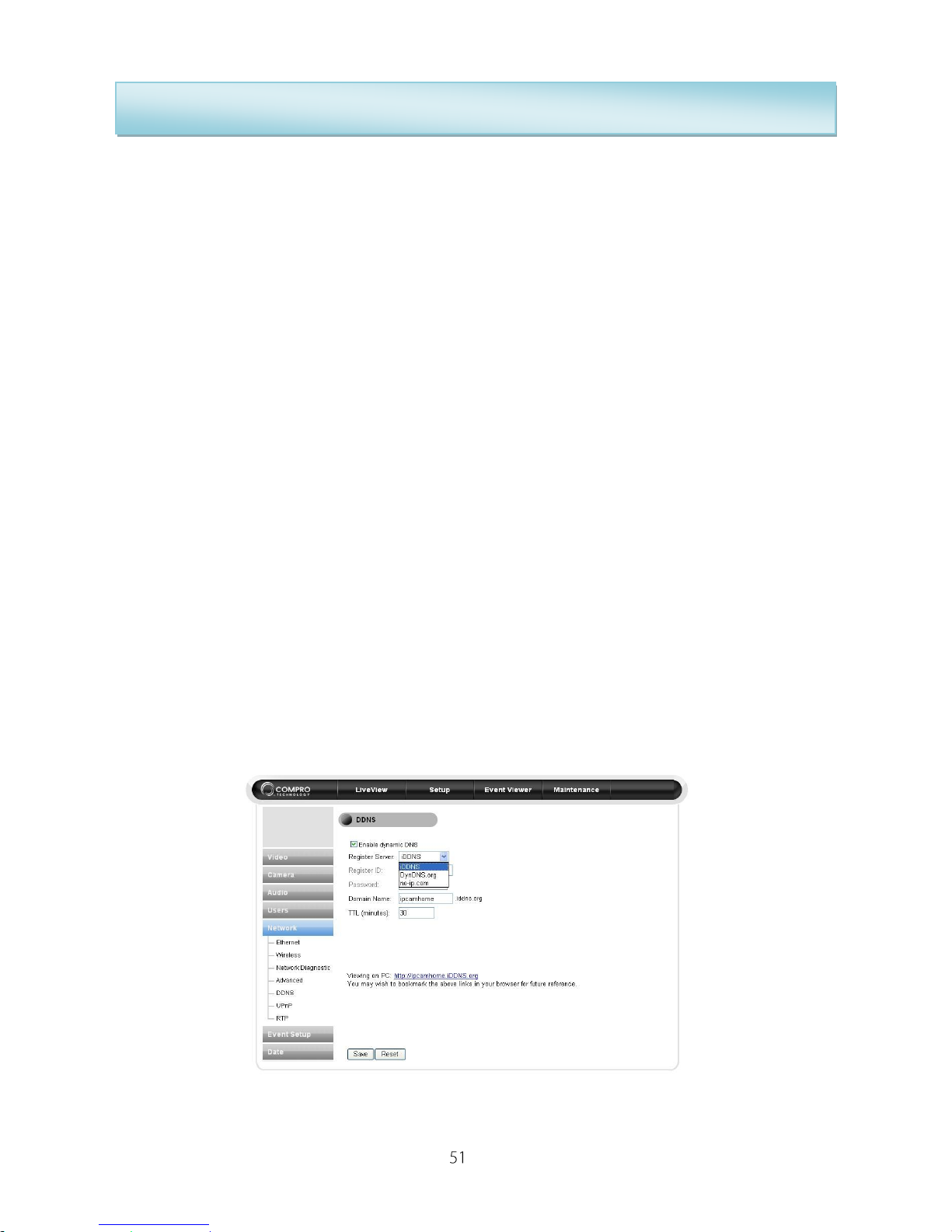
IP Camera. After login the IP Camera, please go for Setup Network
DDNS and enter the entire DDNS column.
Page 52
IP540(P) User’s Manual
DDNS Setup and Port Forwarding
Apply Compro iDDNS Service
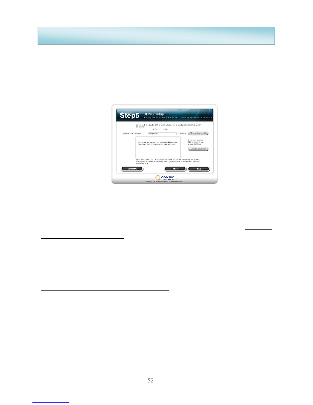
If you want to use Compro iDDNS service, please running the Compro iWizard
and click “Yes” in the Step5 and input the address name you desire, then click
“Check Availability” to check the input address name is not being used by
others. When it successes, you can click “Create Shortcut” to create the
shortcut on your desktop for more convenient use.
The iDDNS is a free DDNS service from Compro. If you are using floating IP,
you need to apply the DDNS (Dynamic Domain Name Server) service to
create a hostname that points to your home or office IP address, and provides
easy-to-remember URL for quick access in anytime, anywhere. After
succeeded create the iDDNS address name, you only need to using http://xxx
(input by yourself).iddns.org to access your IP camera from browser.
If your local LAN and router have setup firewall to prevent attack from outside,
you have to setup the http port from your router.
For example, if you are setting the http port “2001” for your IP camera, your IP
camera address will be
http://xxx (input by yourself).iddns.org:2001
Page 53
IP540(P) User’s Manual
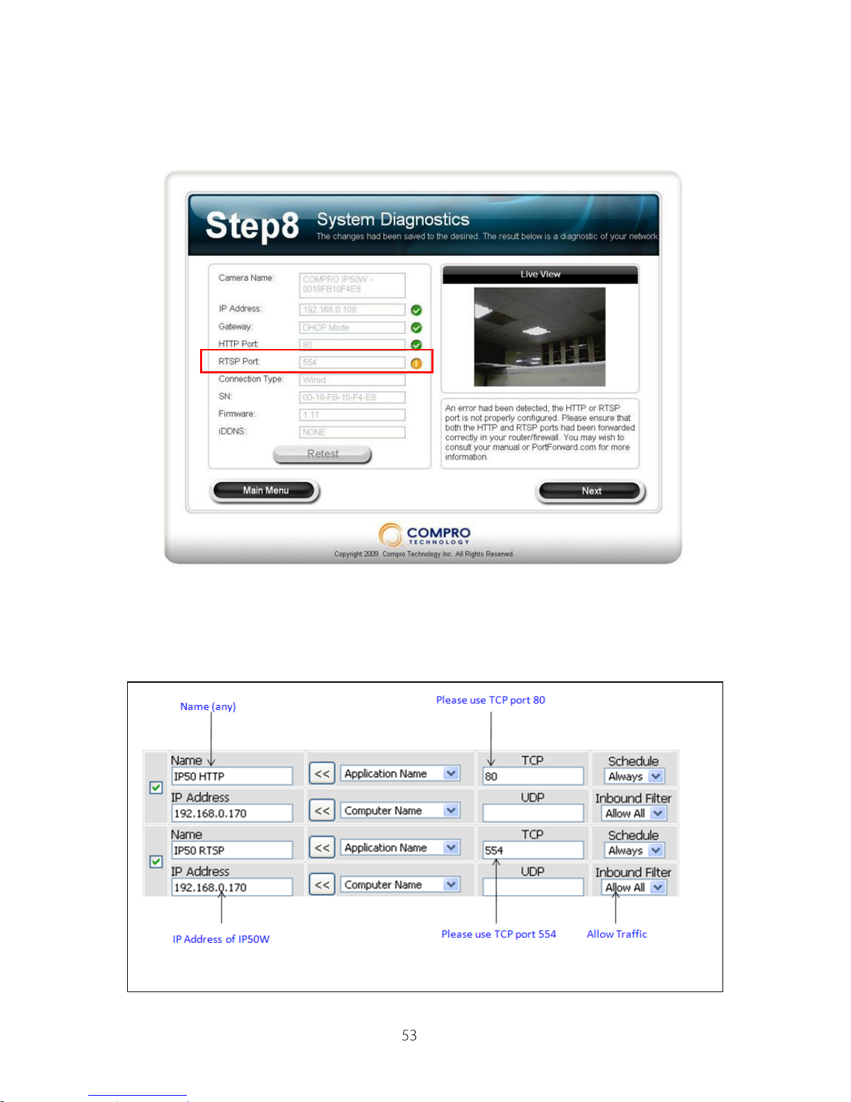
If you see the exclamation mark in the HTTP or RTSP port after setup. That
means you have to setup the port forwarding on your router to enables you
can access the camera from internet.
Please enable port forwarding in the router which the IP camera connected.
You may need to consult the manufacturer of your router. Note: Your router
may require a reboot after port forwarding had been set.
The above is a sample illustration of what you need to do in order to enable
Page 54

IP540(P) User’s Manual
remote viewing of the IP camera.
Once the above steps are done, you should be able to log-on to the camera
from a remote location. Please type in the DDNS address or the static IP
address depending on your configuration. For example, in this case, you
should enter http://61.220.20.16:80 into the Internet Explorer to gain access to
the camera.
Note: If you have multiple cameras installed on a network, you will need to
change the HTTP and RTSP port on the cameras manually so each one of
them will have a unique port. E.g. you may wish to change the HTTP and
RTSP server ports on the 2nd camera to 81 and 554 respectively. You can
access the 2nd camera by typing in http://61.220.20.16:81.
Page 55
IP540(P) User’s Manual
Reset to the Factory Default
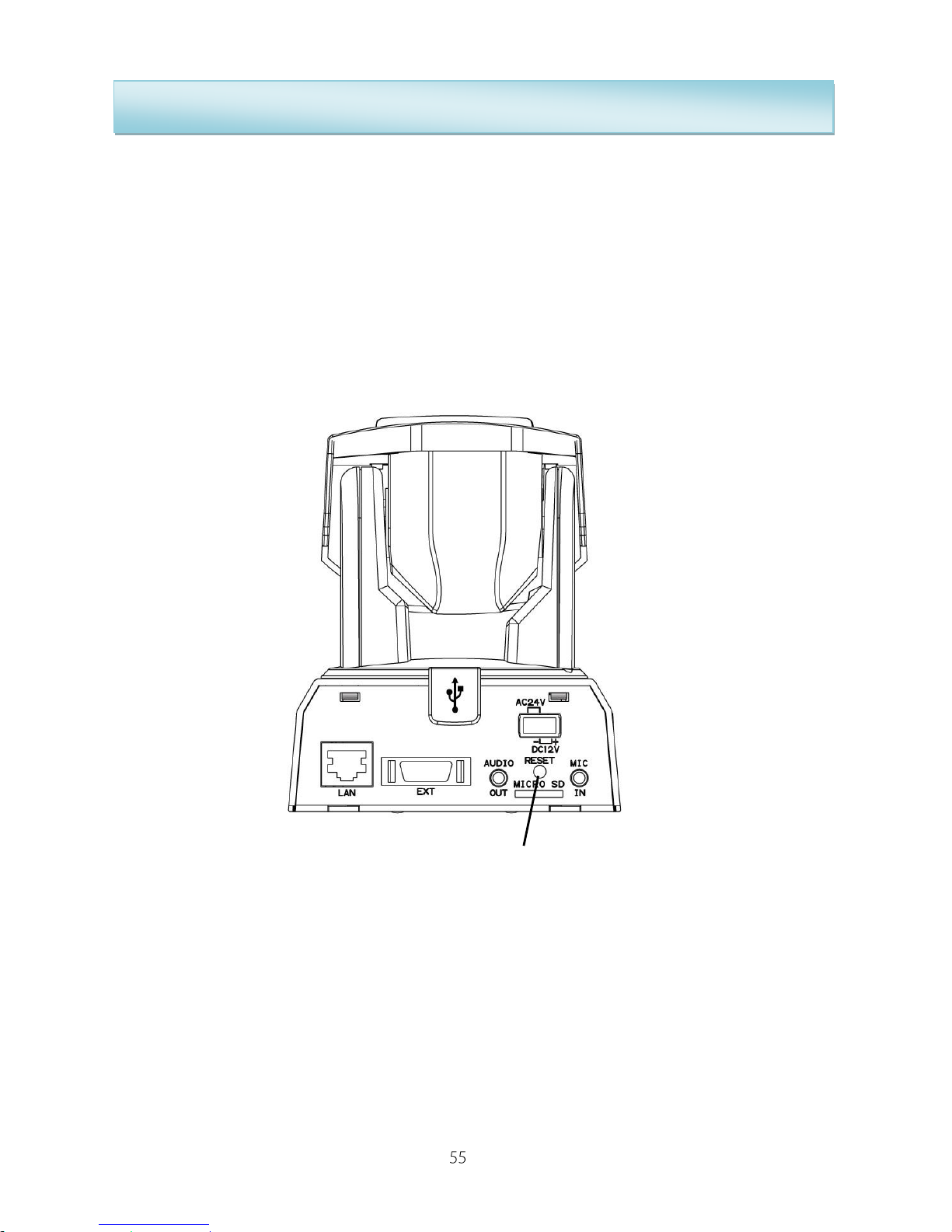
This function will cause the IP camera back to the factory default settings,
please refer the steps below:
1. Keep pressed the reset button (rear panel) about 10 seconds; user will see
the Status Indicator go out.
2. After about 5 seconds, the Status Indicator brightens up again. It means
that the IP camera is back to the factory default.
3. Please re-install the Compro IP540(P) using the one of above method.
Reset Button
Page 56
IP540(P) User’s Manual
Firmware Update
You can download the latest firmware from Compro’s website.
http://www.comprousa.com
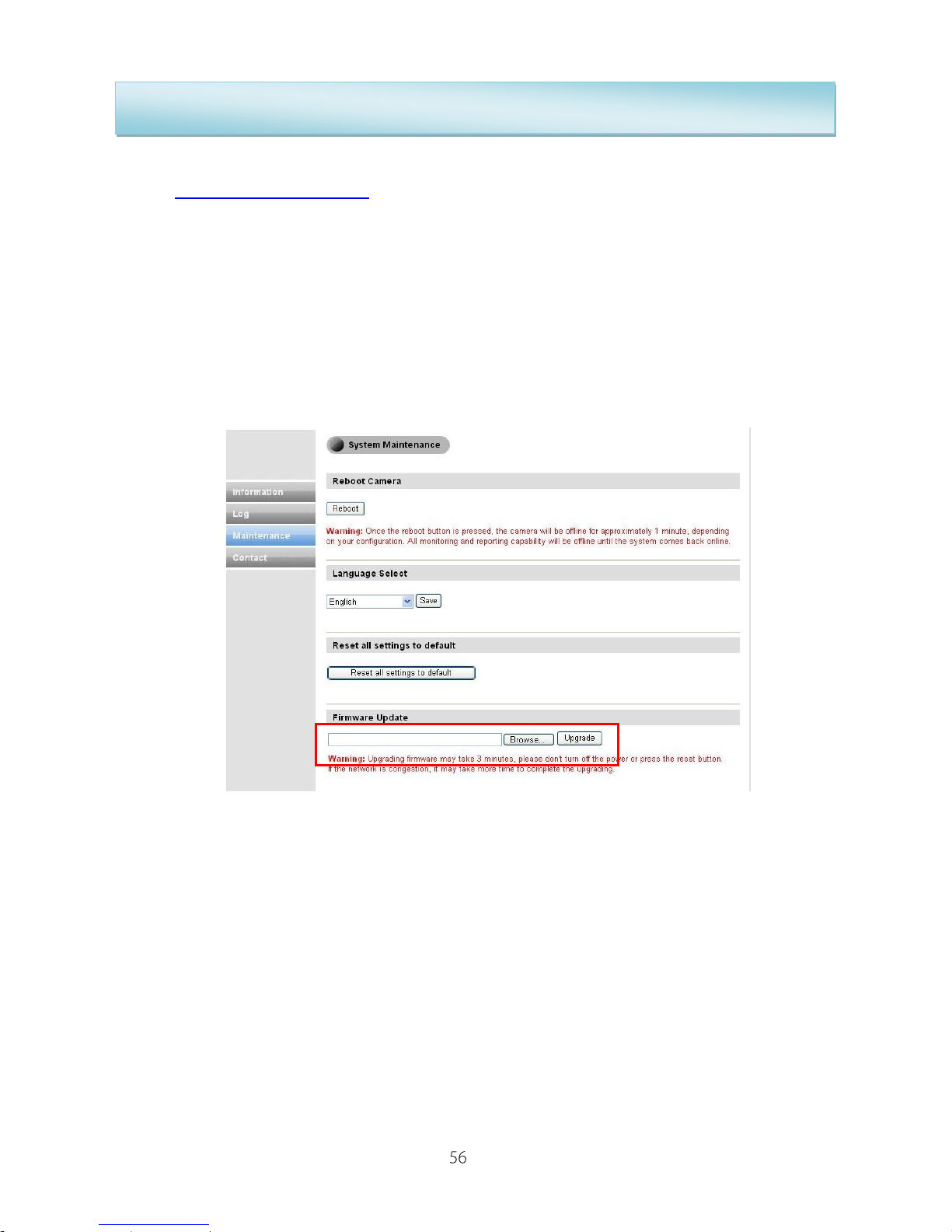
After download the file, please go the web interface of IP camera control, and
select the download file to update your firmware.
Click Setup Maintenance (upper-right) Maintenance (left) and select
firmware update.)
Page 57
IP540(P) User’s Manual
Troubleshooting
During the course of installation, you may encounter various issues in regards
to the usage of either the camera or the ComproView software. The following
pages contain the list of troubleshooting procedures which should help you
overcome any difficulties.
The troubleshooting is divided into four sections, initial setup, stand alone
onboard program, ComproView and remote viewing via Internet Explorer.
Initial Hardware / Software Setup
Installation
After you’ve successfully connected the power and network port of the IP
camera, please ensure that you’ve installed the latest software & firmware
from our website, www.comprousa.com. Once the ComproView had been
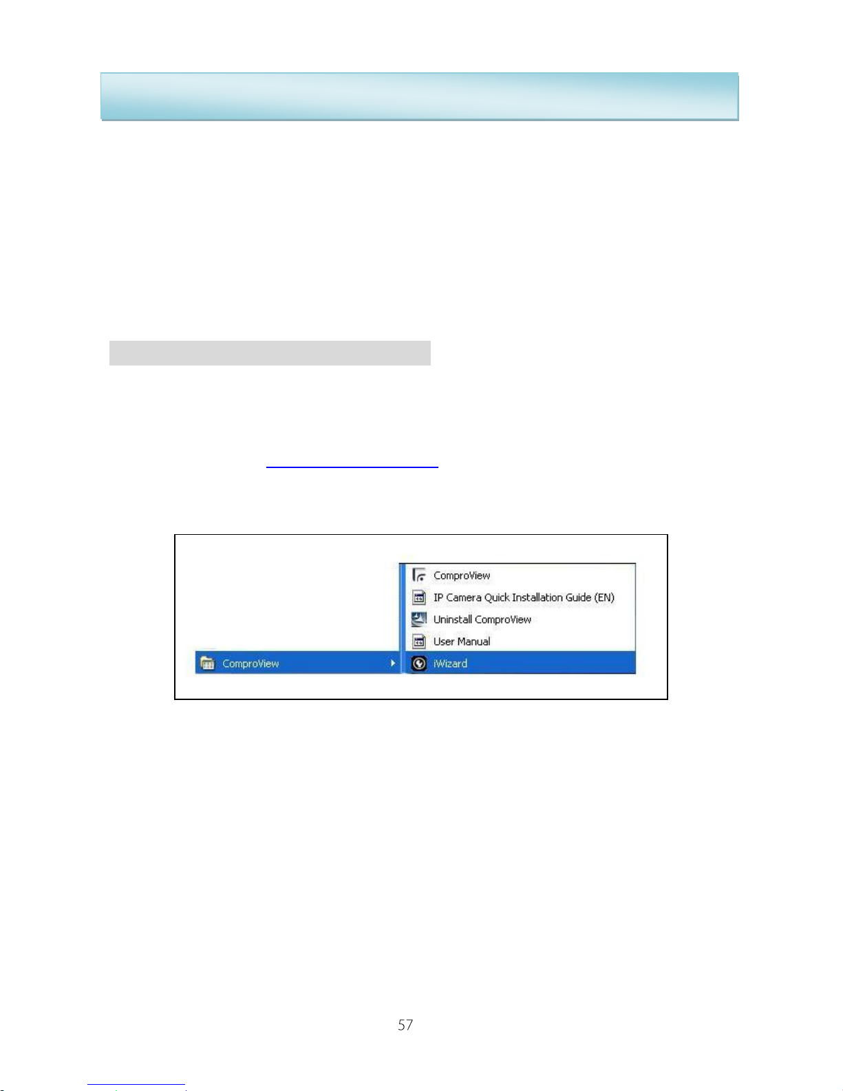
installed, you can use the included iWizard which can be found under Start ->
Program Files -> ComproView.
The iWizard will automatically scan for all of the available cameras on the
network, even though they might not be on the same subnet.
iWizard
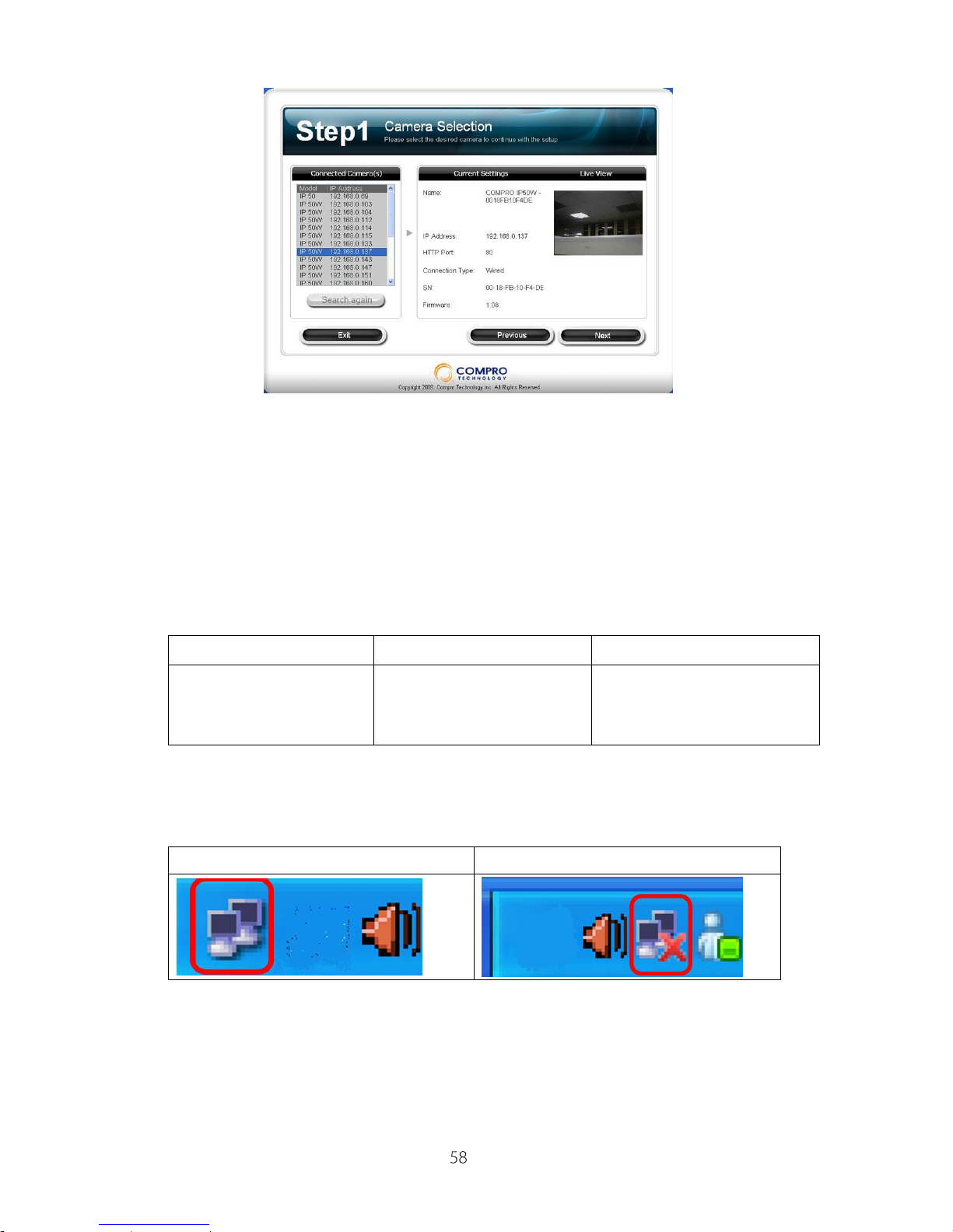
The scanning of the cameras generally takes around 1 minute to complete
and you will see the available cameras populating the screen, as per the figure
blow.
Page 58
IP540(P) User’s Manual
However, should the scanning returned zero cameras found then we can start
the following troubleshooting procedure.
Hardware wiring check
a. Please check that the camera had been connected to either the wired or
wireless network and had been powered on for 1 minute. You can check
the status of the IP camera by checking the front blue LED.
b. Please check that your computer has a successful connection to the
network.
Computer has connection
Computer has no connection
c. If you are using the wireless network, please ensure that:
1. The IP camera is connected to the correct wireless access point.
2. You’ve correctly set the encryption type and key for the connection,
where applicable.
3. If your network does not have a router then the default IP address for
Steady (Blue)
Blinking (Red)
Off
Successful
connection to the
network
The camera is unable
to connect to the
network
The unit is either not
working or the LED had
been turned off.
Page 59
IP540(P) User’s Manual
this camera is at 192.168.0.128.
Note: You can check the status of the connection by logging into your router
maintenance log or similar wordings in your router.
Camera Reset
After you’ve check through the above steps, you should be able to use the
iWizard Utility to scan for the camera which you’ve just installed. If none of the
above worked, please reset the camera and follow the above procedures
again.
You can reset the camera to the default state where it will use the onboard
LAN connection and get IP from the available local DHCP server. To reset the
camera, please power on the camera for 2minutes then press and hold the
reset button on the back of the camera for 10 seconds in order to reset setting
to factory default.
Once the camera had been reset, please give it 2 minutes to reboot and start
the IP Camera Utility to scan for the camera.
Trouble with the ActiveX Client
Once you’ve highlighted the chosen camera, please click on the “Web Page”
button which should start your Internet Explorer. It will ask you for the user
name and password combination, the default is admin/admin, case sensitive.
Note: The application currently only runs under Microsoft Internet Explorer 6
or greater. It does not operate under other internet browsers in the time being.
No user interface in the browser:
This could be related to three possible causes.
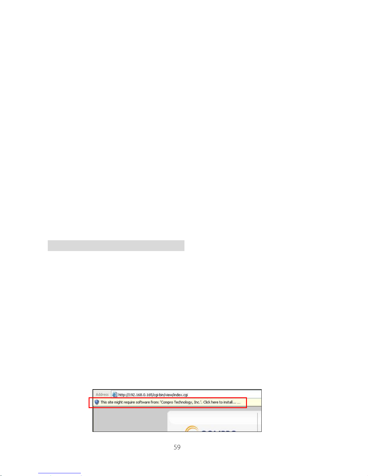
a. ActiveX was not installed: Please install the ActiveX as per the
instruction on the screen. This component must be installed otherwise
you will not have access to the operating user interface.
Page 60
IP540(P) User’s Manual
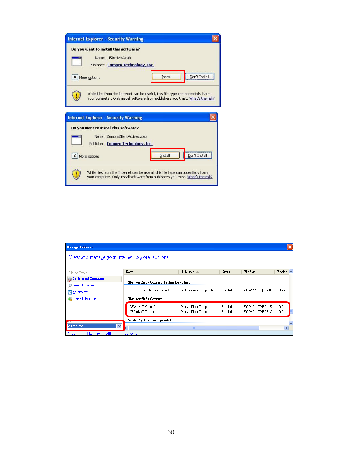
b. Ensure that the ActiveX had been correctly registered with your Internet
Explorer. Please check that you’ve got both the ComproClientActivex
and USActiveX control components registered under Tools -> Manage
Add-ons.
Page 61
IP540(P) User’s Manual
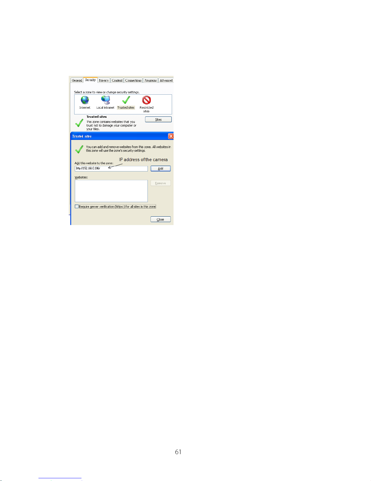
c. Please ensure that your security setting under Internet Explorer allows
the installation of ActiveX component by adding the IP address of the
camera to the list of trusted sites in Internet Explorer.
If you have done all of the above and still unable to get the video / audio on the
browser, please delete all of the files under OS Drive\Program Files\Compro
Embedded and reinstall the ActiveX client. Finally, if you encountered the error
where the browser returned “213 file not found”, please restart your computer
which should help in this situation.
Page 62
IP540(P) User’s Manual
Remote Viewing via Internet Explorer
It is likely that you may wish to check the video or audio of the IP camera from
a remote location. The following are the steps which you will need to perform
in order for a successful viewing.
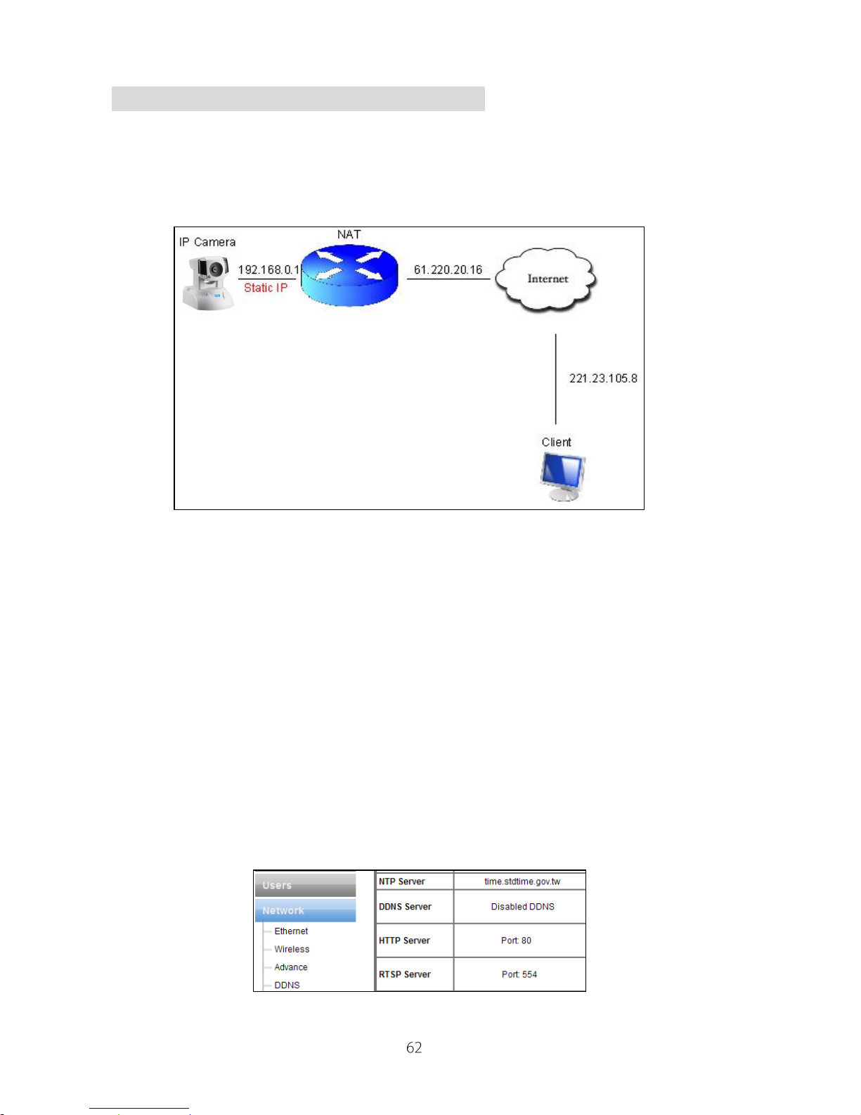
The figure above denotes a general condition where:
a. The IP camera has a static virtual IP address of 192.168.0.1
b. The WAN IP address at the IP camera site is 61.220.20.16.
c. The client (user) is trying to view the video / audio stream remotely.
1. Please ensure that the camera’s image quality is set corresponding to the
host’s upload limit. You can check the camera’s image quality setting under
ActiveX Setup Video Quality. Should you set quality higher than
that of the upload limit, you will experience stutter in video or black video
screen.
2. Check the ports on the camera by going into ActiveX Setup Network
and note down the HTTP and RTSP server ports, in this case, ports 80 and
554 respectively.
Page 63
IP540(P) User’s Manual
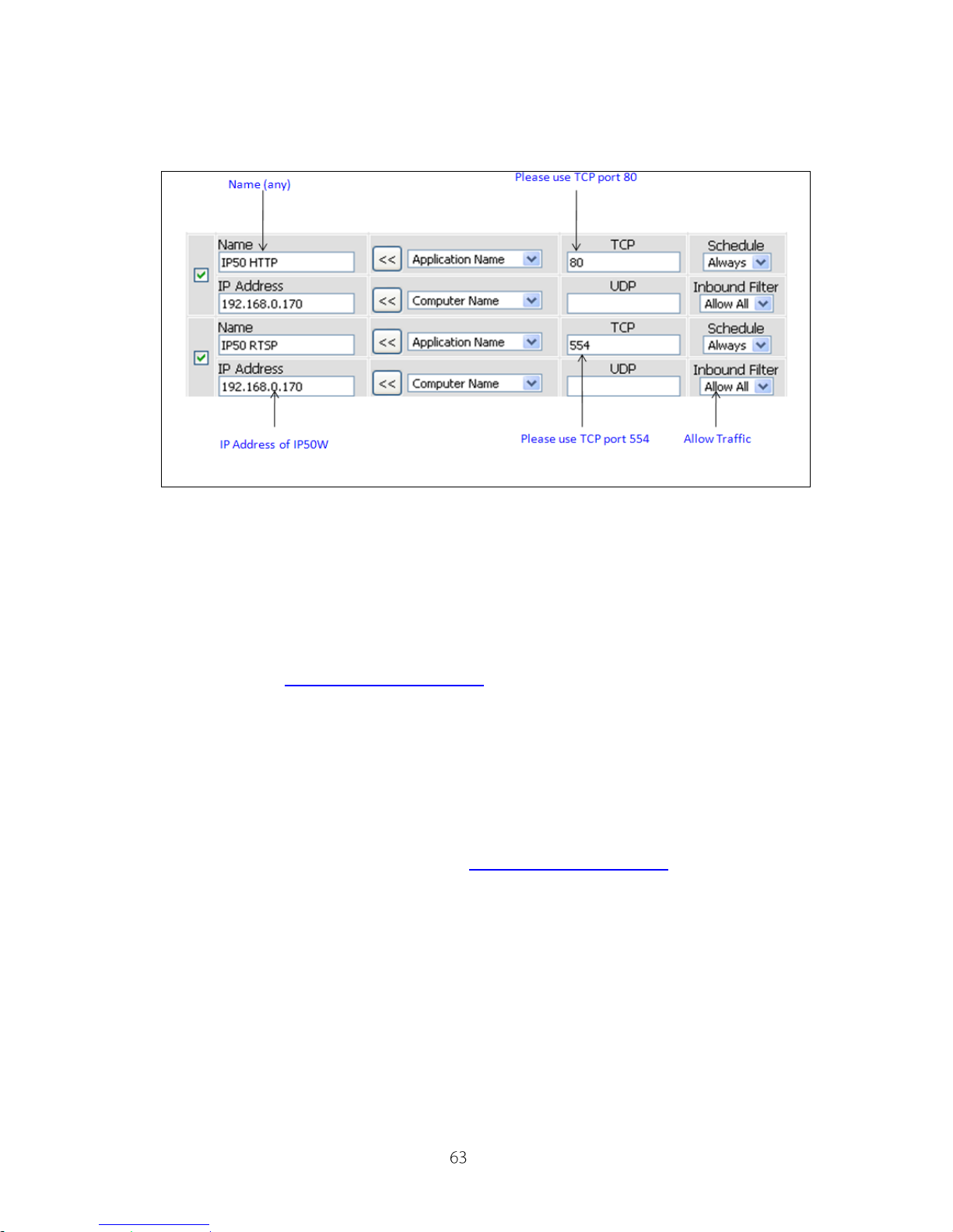
3. Please enable port forwarding in the router which the IP camera connected.
You may need to consult the manufacturer of your router. Note: Your router
may require a reboot after port forwarding had been set.
The above is a sample illustration of what you need to do in order to enable
remote viewing of the IP camera.
4. Once the above steps are done, you should be able to log-on to the camera
from a remote location. Please type in the DDNS address or the static IP
address depending on your configuration. For example, in this case, you
should enter http://61.220.20.16:80 into the Internet Explorer to gain
access to the camera.
Note: If you have multiple cameras installed on a network, you will need to
change the HTTP and RTSP port on the cameras manually so each one of
them will have a unique port. E.g. you may wish to change the HTTP and
RTSP server ports on the 2nd camera to 81 and 554 respectively. You can
access the 2nd camera by typing in http://61.220.20.16:81.
Page 64

IP540(P) User’s Manual
Contacting Compro Technical Support
Before you submit an email for support, please check the troubleshooting list
above. You may fill out the form (http://comprousa.com/en/form.htm) or
directly email to [email protected]
Compro Technology, Inc.
www.comprousa.com
V1.5-100928
 Loading...