

Page 1

Compaq Armada M700
Series of Personal Computers
Reference Guide
Page 2

Compaq Armada M700
Series of Personal Computers
Reference Guide
Page 3

Notice
The information in this guide is subject to change without notice.
COMPAQ COMPUTER CORPORATION SHALL NOT BE LIABLE FOR
TECHNICAL OR EDITORIAL ERRORS OR OMISSIONS CONTAINED
HEREIN; NOR FOR INCIDENTAL OR CONSEQUENTIAL DAMAGES
RESULTING FROM THE FURNISHING, PERFORMANCE, OR USE OF
THIS MATERIAL.
This guide contains information protected by copyright. No part of this
guide may be photocopied or reproduced in any form without prior
written consent from Compaq Computer Corporation.
© 1999 Compaq Computer Corporation.
All rights reserved. Printed in U.S.A., U.K., Singapore, and Taiwan.
COMPAQ and ARMADA are registered in the U.S. Patent and Trademark
Office.
Microsoft, MS-DOS, Windows, Windows NT, and other names of
Microsoft products mentioned herein are trademarks or registered
trademarks of Microsoft Corporation.
Imation and SuperDisk are trademarks of Imation Corporation.
CardWare is a registered trademark of Award Software International Inc.
All other product names mentioned herein may be trademarks or
registered trademarks of their respective companies.
Software described herein is furnished under a license agreement or
nondisclosure agreement. The software may be used or copied only in
accordance with the terms of the agreement.
REFERENCE GUIDE
Compaq Armada M700 Series of Personal Computers
First Edition July 1999
Part Number 103182-001
Compaq Computer Corporation
Page 4

CONTENTS
preface
USING THIS GUIDE ......................................................................................xi
chapter 1
GETTING STARTED
Charging the Battery Pack for the First Time..................................1-1
Connecting the Computer to External Power...................................1-2
Opening the Computer......................................................................1-3
Turning the Computer On.................................................................1-4
Setting Up the Software....................................................................1-4
Operating the Computer During Setup........................................1-5
Choosing a Language...................................................................1-5
Completing Setup .............................................................................1-5
Registering the Computer (North America Only).......................1-5
Locating the Preinstalled Quick Reference Guide ......................1-5
Accessing the Internet.......................................................................1-6
Preinstalled Operating System and Software...................................1-6
chapter 2
COMPUTER AT A GLANCE
Front Components.............................................................................2-1
Rear Components..............................................................................2-2
Left Side Components ......................................................................2-3
Right Side Components....................................................................2-4
Top Components...............................................................................2-5
Bottom Components.........................................................................2-6
chapter 3
NAVIGATION DEVICES AND KEYBOARD
Pointing Stick Model........................................................................3-2
Optional Touchpad Model................................................................3-3
Contents v
Page 5

Hotkeys............................................................................................. 3-4
Switching Displays ...................................................................... 3-4
Adjusting System Volume........................................................... 3-4
Initiating QuickLock/QuickBlank............................................... 3-5
Accessing Power Management.................................................... 3-5
Accessing the Battery Gauge....................................................... 3-5
Accessing the Brightness Control................................................ 3-5
Accessing the Embedded Numeric Keypad................................ 3-6
Stretching Text............................................................................. 3-7
chapter 4
BATTERY PACKS
Battery Components......................................................................... 4-2
Primary Battery............................................................................ 4-2
MultiBay Battery Pack................................................................. 4-3
Charging Battery Packs.................................................................... 4-3
Ensuring Battery Gauge Accuracy................................................... 4-4
Calibrating a Battery Pack................................................................ 4-4
Initiating Calibration.................................................................... 4-5
Stopping Calibration....................................................................4-5
Identifying a Low Battery Condition............................................... 4-6
Resolving a Low Battery Condition................................................. 4-6
Replacing a Battery Pack ................................................................. 4-7
Removing a Primary Battery Pack from the Battery Bay........... 4-7
Inserting a Primary Battery Pack into the Battery Bay............... 4-8
Removing a MultiBay Battery Pack............................................ 4-9
Inserting a MultiBay Battery Pack ............................................ 4-10
Storing Battery Packs.....................................................................4-10
Maximizing Battery Life................................................................ 4-11
Recycling Used Battery Packs....................................................... 4-11
chapter 5
POWER MANAGEMENT
Leaving the Computer On................................................................ 5-1
Turning the Computer Off................................................................ 5-1
Managing Power............................................................................... 5-1
Accessing Power Management........................................................ 5-2
vi Contents
Page 6

Power Management Levels ..............................................................5-2
Suspend.............................................................................................5-2
Benefits of Using Suspend...........................................................5-2
Initiating Suspend.........................................................................5-3
Exiting Suspend............................................................................5-4
Hibernation .......................................................................................5-4
Benefits of Using Hibernation .....................................................5-5
Initiating Hibernation...................................................................5-5
Enabling/Disabling Hibernation ..................................................5-6
Exiting Hibernation......................................................................5-6
Timeout.............................................................................................5-6
Setting Component Timeouts.......................................................5-7
Setting the Screen Saver Timeout................................................5-7
chapter 6
DRIVES
Using Drives .....................................................................................6-1
Caring for Drives..............................................................................6-2
MultiBay Weight Saver....................................................................6-3
Hard Drives.......................................................................................6-4
Removing a Hard Drive from the Hard Drive Bay .....................6-4
Inserting a Hard Drive into the Hard Drive Bay..........................6-5
Removing a Hard Drive from the MultiBay................................6-6
Inserting a Hard Drive into the MultiBay....................................6-7
Inserting a Hard Drive into the MultiBay Adapter......................6-7
CD-ROM and DVD-ROM Drives....................................................6-8
Removing the CD-ROM Drive or DVD-ROM Drive.................6-8
Inserting the CD-ROM Drive or DVD-ROM Drive ...................6-9
Inserting a Disc into the CD-ROM Drive or
DVD-ROM Drive.....................................................................6-10
Removing a Disc from the CD-ROM Drive or
DVD-ROM Drive.....................................................................6-11
Diskette Drive and SuperDisk LS-120 Drive.................................6-12
Removing the Diskette Drive or SuperDisk LS-120 Drive.......6-12
Inserting the Diskette Drive or SuperDisk LS-120 Drive.........6-13
Inserting a Diskette into the Diskette Drive or
SuperDisk LS-120 Drive..........................................................6-14
Removing a Diskette from the Diskette Drive
or SuperDisk LS-120 Drive .....................................................6-15
Connecting the Diskette Drive to the Parallel Connector..............6-16
Contents vii
Page 7

chapter 7
SECURITY
Types of Security.............................................................................. 7-1
DriveLock Feature............................................................................7-2
Overview...................................................................................... 7-2
Establishing DriveLock Protection.............................................. 7-3
Changing the User or Master Password ...................................... 7-4
Removing DriveLock Protection................................................. 7-5
Power-On Password ......................................................................... 7-5
Using the Power-On Password.................................................... 7-5
Setting the Power-On Password .................................................. 7-6
Changing the Power-On Password.............................................. 7-6
Deleting the Power-On Password................................................ 7-7
Setup Password................................................................................. 7-7
Setting the Setup Password.......................................................... 7-7
Changing the Setup Password...................................................... 7-8
Deleting the Setup Password....................................................... 7-8
Keyboard Password Symbols........................................................... 7-8
Enabling/Disabling Quick Controls................................................. 7-9
Disabling and Enabling Devices...................................................... 7-9
Using the Cable Lock..................................................................... 7-10
chapter 8
OPTIONAL INTERNAL MODEM
Modem Overview............................................................................. 8-1
Connecting the Modem.................................................................... 8-2
Understanding How the Modem Works.......................................... 8-3
Changing the Country Selection ...................................................... 8-3
Software Overview........................................................................... 8-4
chapter 9
MEMORY UPGRADE
Removing the Keyboard................................................................... 9-2
Removing a Memory Expansion Board........................................... 9-3
Inserting a Memory Expansion Board.............................................9-4
Replacing the Keyboard................................................................... 9-5
viii Contents
Page 8

chapter 10
ADDITIONAL FEATURES
Identifying Audio Connections ......................................................10-2
Using Internal and External Microphones .....................................10-3
Using Internal and External Speakers............................................10-4
Controlling Audio Volume.............................................................10-5
Infrared Connections ......................................................................10-5
Types of PC Cards..........................................................................10-7
Inserting a PC Card.........................................................................10-8
Removing a PC Card......................................................................10-9
Enabling/Disabling PC Card Slots...............................................10-10
PC Card Device Drivers ...............................................................10-10
Zoomed Video ..............................................................................10-11
Intelligent Manageability..............................................................10-11
Accessing the Web Agent........................................................10-12
Asset Management...................................................................10-12
Fault Management....................................................................10-13
Fault Management Alerts.........................................................10-13
Security Management...............................................................10-14
Configuration Management .....................................................10-14
chapter 11
COMPUTER SETUP AND DIAGNOSTICS
Selecting Computer Setup or Compaq Diagnostics
for Windows.................................................................................11-1
Using Computer Setup....................................................................11-2
File Menu....................................................................................11-3
Security Menu ............................................................................11-4
Advanced Menu..........................................................................11-5
Using Compaq Diagnostics for Windows......................................11-6
chapter 12
CARE, TRAVEL, AND SHIPPING GUIDELINES
Caring for the Computer.................................................................12-1
Operating Temperatures .................................................................12-2
Traveling with the Computer..........................................................12-2
Shipping the Computer...................................................................12-3
Contents ix
Page 9

chapter 13
TROUBLESHOOTING
Obtaining Update Information with Info Messenger.....................13-1
Checklist for Solving Problems ..................................................... 13-2
Solving Audio Problems ................................................................ 13-3
Solving Battery/Battery Gauge Problems...................................... 13-5
Solving CD-ROM Drive/DVD-ROM Drive Problems.................13-7
Solving Diskette Drive/SuperDisk LS-120 Drive Problems......... 13-8
Solving Hard Drive Problems........................................................13-9
Solving Infrared Problems ........................................................... 13-10
Solving Keyboard/Numeric Keypad Problems............................13-12
Solving Modem Problems............................................................ 13-12
Solving PC Card Problems........................................................... 13-16
Solving Power Problems..............................................................13-18
Solving Screen Problems ............................................................. 13-19
Solving USB Problems................................................................. 13-20
appendix A
COMPAQ CUSTOMER SUPPORT
Preparing for a Technical Support Call .......................................... A-1
Worldwide Telephone Numbers..................................................... A-2
appendix B
REGULATORY NOTICES .................................................................................B-1
appendix C
ELECTROSTATIC DISCHARGE
Preventing Electrostatic Discharge..................................................C-1
When Handling Drives ................................................................C-1
When Installing Internal Components.........................................C-1
Grounding Methods..........................................................................C-2
appendix D
SPECIFICATIONS ...................................................................................... D-1
INDEX .......................................................................................................I-1
x Contents
Page 10

preface
USING THIS GUIDE
Some or all of the following format conventions are used in this
guide to distinguish elements of text:
■ Names of keys are shown in bold type as they appear on the
keyboard, for example,
■ Keys that you should press at the same time are represented by
the key names and the plus (+) symbol, for example,
Ctrl+Alt+Delete.
■ Commands are presented in lowercase, bold type as shown
install or a:\install.
here:
■ An arrow symbol is used to separate names of icons or menus
that you should select in succession, for example, select
Start Å Settings Å Control Panel.
Ctrl, Backspace, Tab.
WARNING: Text set off in this manner indicates that failure to
!
follow directions could result in bodily harm or loss of life.
CAUTION: Text set off in this manner indicates that failure to follow
directions could result in damage to equipment or loss of
information.
IMPORTANT: Text set off in this manner presents clarifying
information or specific instructions.
NOTE: Text set off in this manner presents commentary, sidelights,
or interesting points of information.
Using This Guide xi
Page 11

chapter
1
GETTING STARTED
Before you use your computer for the first time, you will have to
complete some preliminary setup procedures. This chapter
explains how to charge your battery pack for the first time and
how to set up your computer and software.
Charging the Battery Pack for the First Time
The battery pack begins to charge as soon as the computer is
connected to external power. Fully charge the battery pack before
using it for the first time.
A new battery pack must completely charge before the computer
is disconnected from external power. The battery pack is fully
charged when the battery charge light turns off. A battery charges
faster if the computer is not being used.
IMPORTANT: The battery charge level lights on a new battery pack
accurately display the percent of a full charge remaining in the
battery pack only once the battery has been fully charged.
Getting Started 1-1
Page 12
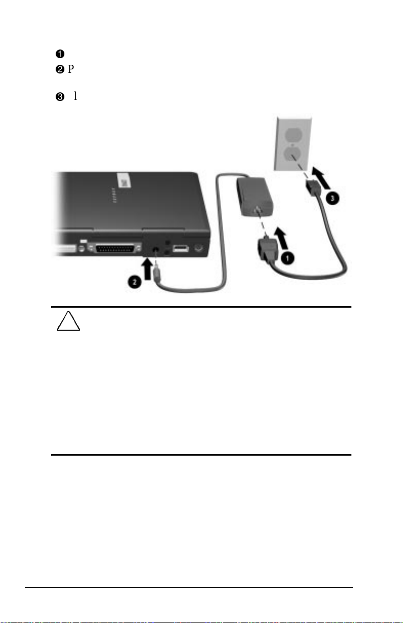
Connecting the Computer to External Power
Plug the power cord into the AC Adapter.
1
Plug the AC Adapter cable into the power connector on the
2
back of the computer.
Plug the other end of the power cord into an electrical outlet.
3
WARNING: To reduce the risk of personal injury, electric shock,
!
fire, or damage to the equipment
■ Do not disable the power cord grounding plug. The grounding
plug is an important safety feature.
■ Plug the equipment into a grounded (earthed) electrical outlet that
is easily accessible at all times.
■ Disconnect power from the equipment by unplugging the power
cord from the electrical outlet.
■ Do not place anything on power cords or cables. Arrange them so
that no one can accidentally step on or trip over them. Do not pull
on a cord or cable. When unplugging from the electrical outlet,
grasp the cord by the plug.
NOTE: In Japan, you must first plug the power cord into the
3-to-2-prong plug adapter included with the computer. Ensure that
the ground wire is connected to a safe earth ground, then plug the
3-to-2-prong plug adapter into the electrical outlet.
1-2 Getting Started
Page 13
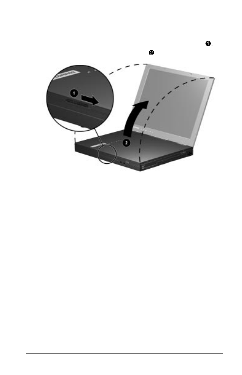
Opening the Computer
To open the computer,
1. Slide the display latch located on the front of the display 1.
2. Lift the display to the desired angle 2.
Getting Started 1-3
Page 14
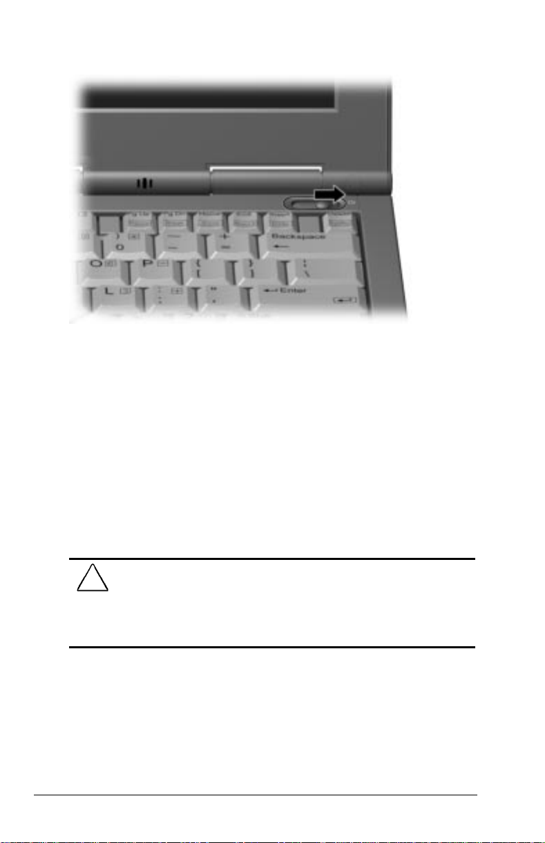
Turning the Computer On
To turn the computer on, slide the power switch and release it.
If the computer is only connected to external AC power, the
computer will start up automatically when you plug it in.
Setting Up the Software
When you begin software setup, online instructions guide you
through the setup process.
IMPORTANT: After you begin software setup, you must complete the
entire process. Make sure the computer is plugged into an external
power source to ensure that software setup is not interrupted.
CAUTION: To prevent file corruption and ensure the correct
software drivers are installed
■ Do not dock the computer in a docking station.
■ Do not turn off or unplug the computer or remove a drive during
software setup.
1-4 Getting Started
Page 15

Operating the Computer During Setup
■ To move around the screen while making selections and
entering information
■ press the Tab key,
■ press the cursor (arrow) keys, or
■ use the navigation device built into the computer keyboard.
■ To save your selections, press the Enter key or press the left
navigation device button on the computer keyboard.
■ To restore the screen if it is cleared by the screen saver during
a period of keyboard and navigation device inactivity, press
the Shift key.
For more information about using the built-in navigation devices,
refer to Chapter 3, “Navigation Devices and Keyboard.”
Choosing a Language
If you are prompted to select your language, choose carefully.
IMPORTANT: The languages that you do not choose will be deleted
from the computer and cannot be recovered.
Completing Setup
Registering the Computer (North America Only)
Be sure to register the computer according to the instructions on
the Register Now card included with the computer.
Locating the Preinstalled Quick Reference Guide
To access the quick reference guide,
■ Select the Armada Quick Reference icon on the desktop
or
■ Select StartÅCompaq Information CenterÅArmada
Quick Reference
Getting Started 1-5
Page 16

Accessing the Internet
Internet Explorer 4 has been preinstalled on your computer. To
access the Internet from your desktop, double-click on the Internet
Explorer icon. Internet Explorer will walk you through the steps to
set up your personal Internet connection. You must be connected
to a modem or a network to access the Internet.
Preinstalled Operating System and Software
Either Microsoft Windows 95, Microsoft Windows 98, or
Microsoft Windows NT 4.0 Workstation is preinstalled on the
computer.
Compaq has enhanced the preinstalled operating system on the
computer to provide you with additional software features and
increased computer functionality.
Before deleting the operating system preinstalled on the computer,
please read the following caution:
CAUTION:
■ Replacing the preinstalled Windows 95, Windows 98, or Windows
NT 4.0 operating system with a retail version will result in the
loss of all Compaq enhancements.
■ Most preinstalled reference files, such as Help files, are available
only through the Windows 95, Windows 98, or Windows NT 4.0
interface. If the operating system is removed from the computer,
these reference files will become unavailable.
■ Complete USB support is available only through Windows 98.
Installing an operating system other than Windows 95 or
Windows 98 may result in a loss of USB functionality.
In addition to the operating system, Compaq installs other
software to provide additional functionality or enhancements. If it
is necessary to reinstall the operating system and you do not want
to lose these enhancements, it will also be necessary to reinstall all
Compaq software for your computer. These enhancements are
available at the Compaq Web site (www.compaq.com) and from
the Compaq QuickRestore CD-ROM Kit included with your
computer.
1-6 Getting Started
Page 17
chapter
2
COMPUTER AT A GLANCE
This chapter introduces you to the physical components of your
computer. The components are identified individually along with
brief descriptions.
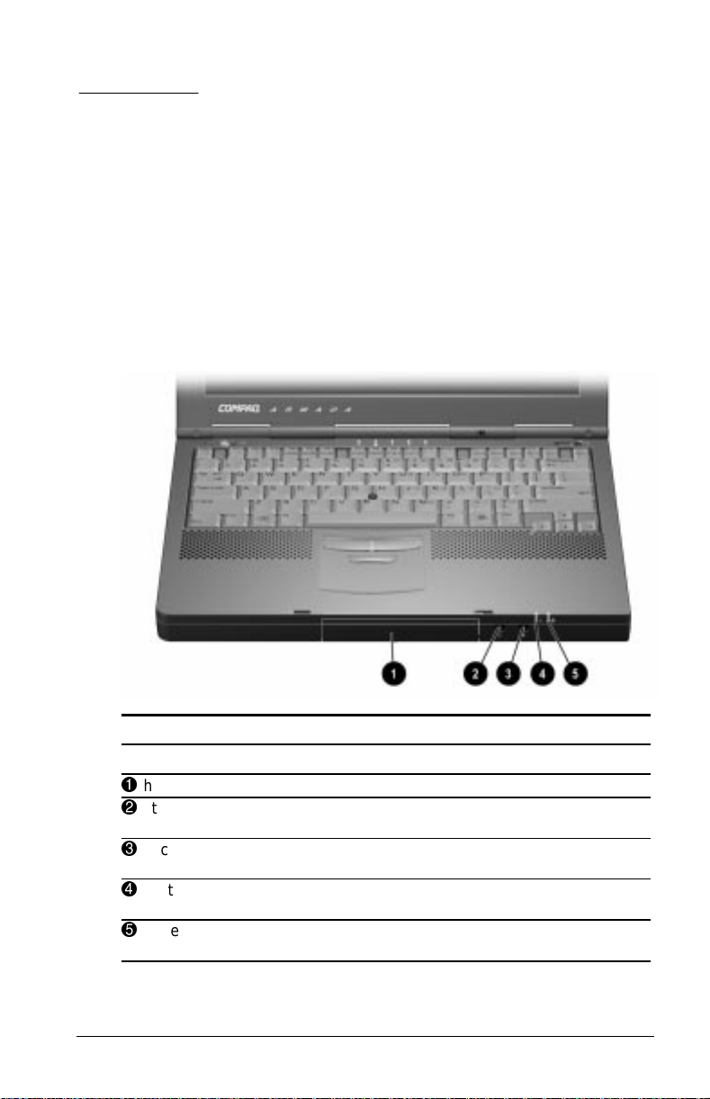
Front Components
Front Components
Component Description
1
hard drive bay Holds the hard drive in the computer.
2
stereo speaker/headphone
jack
3
microphone jack Connects an external microphone to
4
system-on light Indicates that the computer is turned
5
battery charge light Indicates that the computer is
Connects external speakers or
headphones to the computer.
the computer.
on.
charging a battery pack.
Computer at a Glance 2-1
Page 18
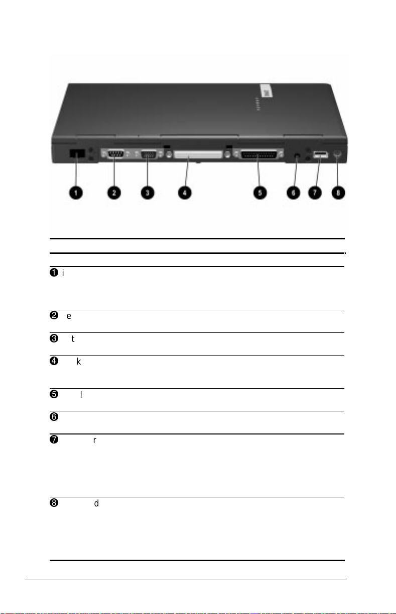
Rear Components
Rear Components
Component Description
1
infrared port Allows wireless communication
2
serial connector Connects an optional external serial
3
external monitor connector Connects an optional external display,
4
docking connector 176-pin expansion bus connector that
5
parallel connector Connects an optional parallel device,
6
power connector Connects the AC Adapter to the
7
USB port Allows you to attach the computer to a
8
keyboard/mouse connector Connects an optional full-sized
between the computer and another
infrared-equipped device, such as a
computer or printer.
device, such as a mouse.
such as an external monitor.
connects the computer to the desktop
expansion base or convenience base.
such as a printer.
computer.
Universal Serial Bus (USB) device,
such as a camera for video. Or, you
can attach a hub, which would allow
you to connect multiple USB devices to
the computer.
keyboard or a PS/2 compatible mouse.
A generic splitter/adapter will allow the
connection of both an external
keyboard and external mouse at the
same time.
2-2 Computer at a Glance
Page 19
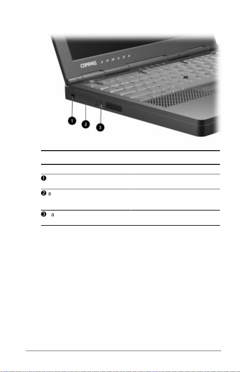
Left Side Components
Left Side Components
Component Description
1
composite TV-out connector Connects a television, VCR,
2
airflow vent Allows airflow needed to cool
3
cable lock connector Attaches an optional security cable
camcorder, or overhead projector.
computer components. Do not
block airflow vents.
to the computer.
Computer at a Glance 2-3
Page 20
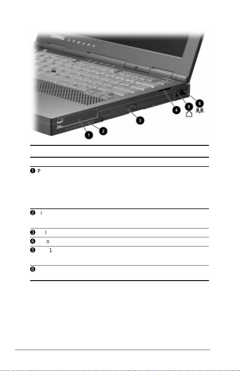
Right Side Components
Right Side Components
Component Description
1
PC Card slots
2
airflow vent
3
MultiBay
4
sound vent
5
RJ-11 jack
6
RJ-45 jack Connects a network cable to the
Hold PC Cards:
■ 2 Type-1
■ 2 Type-2
■ 1 Type-1 and 1 Type-2, or
■ 1 Type 3
Allows airflow needed to cool
computer components. Do not
block airflow vents.
Supports MultiBay devices.
Enhances stereo sound.
Connects a standard telephone
cable or modem cable to the
computer.
computer.
2-4 Computer at a Glance
Page 21
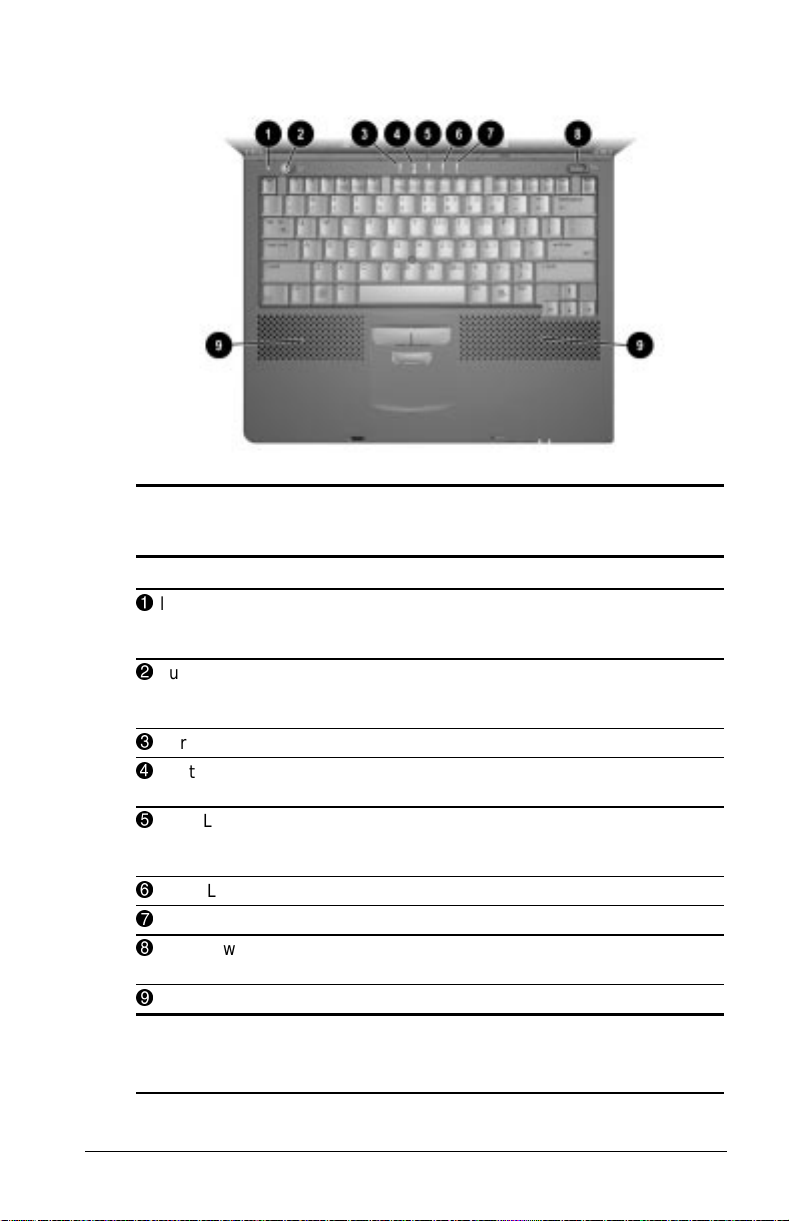
Top Components
Top Components
NOTE: Navigation device components are described in Chapter 3.
Component Function
1
lid switch Turns off the computer display if the
2
suspend button* Initiates and exits Suspend.** When
3
hard drive light Indicates hard drive activity.
4
MultiBay drive light Indicates MultiBay or external diskette
5
Num Lock light Indicates that Num lock is on and the
6
Caps Lock light Indicates that Caps lock is on.
7
Scroll Lock light Indicates that Scroll lock is on.
8
power switch Turns the computer on or off or exits
9
internal speakers Produce stereo sound.
*In Windows 98 the term
button.
**In Windows 98 the term
sleep button
Standby
computer is closed while still turned
on.
pressed with the Fn key, initiates
Hibernation.
drive activity.
embedded numeric keypad is
enabled.
Suspend.
replaces the term
replaces the term
suspend
Suspend.
Computer at a Glance 2-5
Page 22
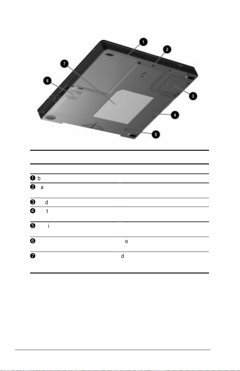
Bottom Components
Bottom Components
Component Description
1
battery bay Holds the primary battery.
2
hard drive security screw Secures the hard drive in the hard
3
modem slot cover Contains the modem board.
4
MultiBay notch Helps remove a drive or battery
5
MultiBay release latch Releases a removable drive or
6
fan Provides airflow to cool internal
7
label Identifies computer and provides
drive bay.
pack from the MultiBay.
battery pack from the MultiBay.
components.
the serial number needed when
calling Compaq customer support.
2-6 Computer at a Glance
Page 23

chapter
3
NAVIGATION DEVICES AND
KEYBOARD
Your computer has either a pointing stick or touchpad feature that
performs the same functions as a mouse. This chapter explains
how to navigate through applications using the pointing stick,
touchpad, and keyboard.
Navigation Devices and Keyboard 3-1
Page 24
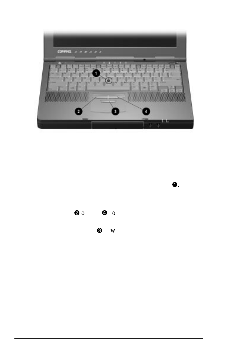
Pointing Stick Model
The EasyPoint IV pointing stick and buttons perform the same
basic operations as a mouse. The pointing stick senses finger
movement although the device itself does not move.
To operate the pointing stick model
1. Place your index finger on top of the pointing stick 1.
2. Push in the direction you want the cursor to move on the
display.
3. Click the left 2 or right 4 pointing device buttons with your
thumb.
4. Hold the scroll button 3 down and push up or down on the
pointing stick to scroll through a document.
3-2 Navigation Devices and Keyboard
Page 25
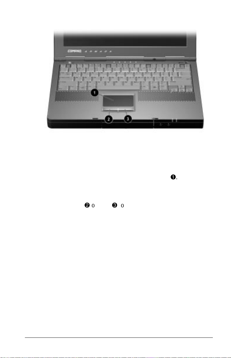
Optional Touchpad Model
The touchpad and buttons perform the same basic operations as a
mouse.
To operate the touchpad model
1. Place your index finger on top of the touchpad 1.
2. Slide your finger in the direction you want the cursor to move
on the display.
3. Click the left 2 or right 3 touchpad buttons with your thumb.
Navigation Devices and Keyboard 3-3
Page 26

Hotkeys
NOTE: Hotkeys work only on the computer keyboard and not on an
external keyboard.
Hotkey Quick Reference
Return to
Function Hotkeys
Switching Displays Fn+F4 Fn+F4
Adjusting System Volume Fn+F5 Fn+F5
Initiating QuickLock/
QuickBlank
Accessing Power Management Fn+F7 Fn+F7
Accessing the Battery Gauge Fn+F8 Fn+F8
Accessing the Brightness Control Fn+F10 Fn+F10
Accessing the Embedded
Numeric Keypad
Stretching Text Fn+T Fn+T
Fn+F6 Enter power-on
Fn+NumLk Fn+NumLk
Switching Displays
When an external monitor is connected to the computer, press the
Fn+F4 hotkeys as a toggle function to
■ Switch to computer display (default).
■ Switch to external monitor or television.
■ Turn on both displays simultaneously.
Original State
password
Adjusting System Volume
Press the Fn+F5 hotkeys to adjust the overall system volume.
Double-click on the speaker icon on the Windows taskbar to adjust
the volume of individual system components.
3-4 Navigation Devices and Keyboard
Page 27

Initiating QuickLock/QuickBlank
IMPORTANT: Before QuickLock/QuickBlank can be initiated, a
power-on password must be established and QuickLock/
QuickBlank must be enabled through Computer Setup.
Press the Fn+F6 hotkeys to initiate QuickLock/QuickBlank at any
time and from within any application. These hotkeys
■ Disable the keyboard and the pointing device.
■ Clear the display.
To reenable the keyboard and return your information to the
screen, enter your power-on password.
Accessing Power Management
Press the Fn+F7 hotkeys to access Power Management. These
hotkeys let you customize the level of battery conservation, or use
one of the three preset conservation levels.
Use the left or right arrow keys to select a different level.
Accessing the Battery Gauge
Press the Fn+F8 hotkeys to show the status of the battery packs.
Three numbered boxes indicate the status of each installed battery.
Press the right or down arrow key to view the status of the next
battery pack. If a battery pack is not in a bay, the corresponding
bay cannot be selected. Press the left or up arrow key to select the
previous battery pack.
Accessing the Brightness Control
Press the Fn+F10 hotkeys to adjust the screen brightness
with an onscreen slide button or with the arrow keys.
Navigation Devices and Keyboard 3-5
Page 28
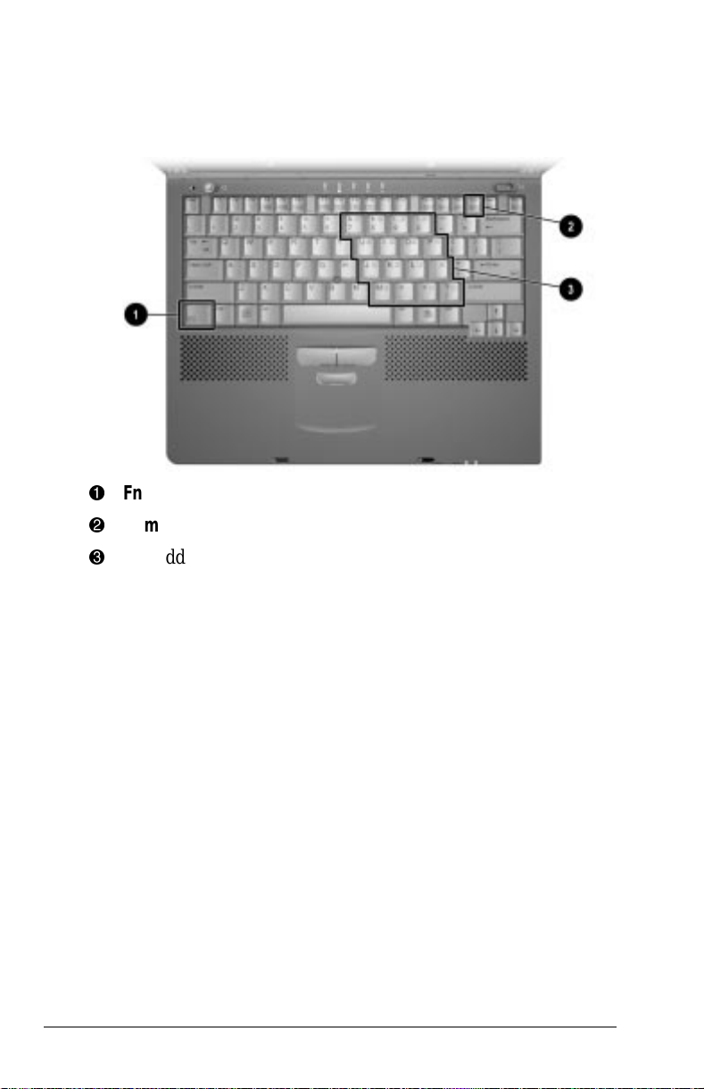
Accessing the Embedded Numeric Keypad
The embedded numeric keypad is a section of the computer
keyboard that converts to a numeric keypad when the number lock
function is enabled.
Fn key
1
Num Lk key
2
embedded numeric keypad
3
Press Fn+Num Lk to
■ Enable the embedded numeric keypad (Num Lk light on).
■ Disable the embedded numeric keypad (Num Lk light off).
With the number lock function enabled,
■ Press Fn to type lowercase letters.
■ Press Fn+Shift to type uppercase letters.
3-6 Navigation Devices and Keyboard
Page 29

Stretching Text
When running MS-DOS under Windows, the image on the
computer display may not fill the screen.
To stretch text so that it fills more of the screen, use the Fn+T
keys. Toggle these keys to switch between stretched text mode and
regular mode. The default is for the Text Stretch feature to be
enabled.
The Fn+T function is available whenever the desktop area
resolution is set lower than the resolution of the internal display
device (LCD).
Navigation Devices and Keyboard 3-7
Page 30

chapter
4
BATTERY PACKS
Your computer can be powered by battery packs or by an external
power source. A battery pack gives you the freedom to carry your
computer from place to place while you work, without plugging
the computer into an external outlet each time.
This chapter identifies the battery components and provides
helpful information about using battery packs.
Battery Packs 4-1
Page 31

Battery Components
Both the primary and MultiBay battery packs let you check their
remaining charge levels before you insert them into their bays.
Primary Battery
To see how much power is left in the primary battery pack, press
the battery gauge button 1. Five battery charge level lights
indicate the remaining charge level.
2
Each battery charge light represents approximately 20 percent of
remaining charge.
4-2 Battery Packs
Page 32

MultiBay Battery Pack
To see how much power is left in the MultiBay battery pack, press
the battery gauge button 1. Five battery charge level lights
indicate the remaining charge level.
Each battery charge light represents approximately 20 percent of
remaining charge.
Charging Battery Packs
2
WARNING: To reduce the risk of injury or damage to the battery
!
pack, do not crush, puncture, or incinerate the battery pack or short
the metal contacts. Do not attempt to open or service the battery
pack.
To charge the battery pack while it is in the computer, connect the
computer to an external power source (external power, desktop
expansion base, or convenience base).
The battery charge light turns on when the battery pack is
charging.
Charging may not occur immediately if the battery pack
temperature is outside the normal operating range of 50°F to
104°F (10°C to 40°C).
Battery Packs 4-3
Page 33

When the battery reaches the normal temperature level, it begins
to charge until charging is complete.
A fully discharged battery pack charges in several hours. Charge
time depends on the amount of power being used by the computer.
Ensuring Battery Gauge Accuracy
The battery gauge built into your computer displays the amount of
charge remaining and is precalibrated for accuracy (To access the
battery gauge, press the
Fn+F8 hotkeys). To ensure continued
battery gauge accuracy and to maximize battery operating time
■ Fully charge a battery pack prior to the first time that you use
it with the computer.
■ Allow the battery pack to completely charge before removing
external power from the computer, optional desktop expansion
base, convenience base, or battery charger.
Calibrating a Battery Pack
If your battery charge display seems inaccurate, you may need to
recalibrate your battery pack. This may take several hours, so a
good time to do this is overnight. The calibration utility supports
both the primary and MultiBay battery packs. Check the
calibration status of your batteries by accessing the Battery
Calibration tab:
■ In Windows 95 select StartÅSettingsÅControl
PanelÅPowerÅBattery Calibration tab.
■ In Windows NT 4.0 select StartÅSettingsÅControl
PanelÅCompaq PowerÅBattery Calibration tab.
■ In Windows 98 select StartÅSettingsÅControl
PanelÅPower ManagementÅBattery Calibration tab.
View the battery calibration reports in the Status column. A
battery pack can only be calibrated if the Status column beside a
battery pack reports “Needs Calibration.”
The Battery Calibration utility calibrates one battery pack at a time
by fully discharging it, then fully recharging it. It can run in the
background as you use the computer.
4-4 Battery Packs
Page 34

Initiating Calibration
1. Connect the computer to an external power source.
CAUTION: To prevent loss of data, ensure that the computer
remains connected to external power throughout calibration.
2. Turn the computer on.
3. Insert the battery pack into the computer battery bay or
MultiBay.
4. Access the Battery Calibration tab.
5. Select the battery pack needing calibration.
6. Select Start Calibration.
NOTE: During calibration, a battery calibration icon displays in
the taskbar. A Down arrow displays while the battery pack is
discharging and an Up arrow displays while the battery pack is
recharging.
Stopping Calibration
Calibration will not resume if it is stopped before calibration is
completed or if the computer is shut down during calibration. An
interrupted calibration must be restarted.
To stop calibration, shut down the computer.
Or,
1. Access the Battery Calibration tab.
2. Select the battery pack being calibrated.
3. Select Stop Calibration. This selection is only visible during
calibration.
Battery Packs 4-5
Page 35

Identifying a Low Battery Condition
When a low battery condition occurs, the computer beeps every 15
seconds and the battery power light blinks.
CAUTION: When you are alerted to a low battery condition, very
little battery charge remains. Take immediate action to resolve the
low battery condition.
When a low battery condition is reached, save your files and
initiate Hibernation before replacing the battery pack.
When a critical low battery condition occurs, the system initiates
Hibernation. It is recommended that Hibernation be enabled at all
times to safeguard against possible data loss in a critical low
battery condition.
CAUTION: If Hibernation is disabled, the computer does not initiate
Hibernation when a critical low battery condition is reached. When
this occurs, all unsaved data is lost.
Resolving a Low Battery Condition
Resolve a low battery condition when another power source is
available by using one of these methods:
■ Connecting to external power (refer to Chapter 1)
■ Charging with an optional external Battery Charger
■ Connecting to the optional Automobile Power
Adapter/Charger
■ Connecting to the optional Aircraft Power Adapter (Does not
charge battery packs.)
■ Docking the computer in an optional docking base that is
connected to external power
■ Replacing the battery pack
4-6 Battery Packs
Page 36

Resolve a low battery condition without a power source by
■ Initiating Hibernation until a power source is available, or
■ Saving your information and shutting down the computer until
a power source is available.
Replacing a Battery Pack
You can resolve a low battery condition by replacing a
discharged battery pack with a charged one. Always save
your work before changing a battery pack.
CAUTION: If you are removing a battery pack that is the only power
source available to the system while the computer is on, initiate
Hibernation before removing the battery pack. Failure to do so will
result in lost information.
If the computer is on and connected to more than one power source,
you can remove a battery pack without initiating Hibernation.
Removing a Primary Battery Pack from the Battery Bay
1. If a battery pack is your only power source, initiate
Hibernation.
NOTE: If there is drive activity, Hibernation may not occur
instantly.
2. Close the display.
Battery Packs 4-7
Page 37

3. Tilt the computer up 1 and push the battery release latch
below the battery bay toward the fan 2 to release the battery
pack.
4. Remove the battery pack from the battery bay 3.
Inserting a Primary Battery Pack into the
Battery Bay
1. Close the display.
2. Tilt the computer up 1.
3. With the smooth side of the battery pack facing up and the
battery cells facing in, lead the rounded edge of the battery
pack into the battery bay. Angle the battery pack into the bay
until it is fully seated 2.
4. If the computer is in Hibernation, slide the power switch to
resume normal operation.
4-8 Battery Packs
Page 38

Removing a MultiBay Battery Pack
1. If a battery pack is your only power source, initiate
Hibernation.
2. With the MultiBay facing you, tilt the computer up 1 and
slide the MultiBay release latch toward the opening of the
bay 2.
3. Grasp the edge of the battery pack at the notch under the
battery pack and pull it out of the MultiBay 3.
Battery Packs 4-9
Page 39

Inserting a MultiBay Battery Pack
With the battery pack charge level lights facing up and the battery
contacts facing in, insert the battery pack into the MultiBay.
If the computer is in Hibernation, slide the power switch to resume
normal operation.
Storing Battery Packs
To prolong the battery charge of a stored battery pack, store it in a
cool, dry place. High temperatures cause a battery pack to lose its
charge more quickly, thus reducing battery life.
The recommended storage temperature range is from 32°F to 86°F
(0°C to 30°C).
CAUTION: To prevent damage to a battery pack, do not expose it to
high temperatures for extended periods of time.
4-10 Battery Packs
Page 40

Maximizing Battery Life
Battery pack operating time varies depending on the system
components, options, and applications being used. You can
maximize battery operating time by controlling the energy
required by the computer and the energy stored in the battery
pack.
The display, processor, CD-ROM drive, DVD-ROM drive, and
hard drive components use the majority of battery power.
To maximize battery pack life
■ Select the High level of power management through Computer
Setup.
■ Initiate Suspend, Hibernation, or turn the computer off when
not in use.
■ Reduce the display brightness and select a shorter screen save
timeout.
■ Calibrate the battery pack periodically to maintain the
accuracy of the battery gauge.
■ Keep a battery pack in the computer when connected to an
external power source.
■ Disconnect external equipment that does not have its own
power source when not in use. (External equipment connected
to the computer drains the battery pack.)
■ Exit modem and networking programs when not in use.
■ Stop or remove any PC Cards when not in use.
■ Format diskettes using external power. (Formatting increases
battery pack drain.)
Recycling Used Battery Packs
To find out if the battery pack recycling program is available in
your geographical location, check the worldwide telephone
numbers in Appendix A. If a number for recycling is not listed for
your area, contact your Compaq authorized dealer, reseller, or
service provider.
For more information, see the “Battery Notice” in Appendix B.
Battery Packs 4-11
Page 41

chapter
5
POWER MANAGEMENT
This chapter provides helpful information on maintaining and
managing battery pack power. You also will find useful
information about the Suspend and Hibernation features.
Leaving the Computer On
When you need to leave your computer unattended but you do not
want to turn it off, conserve power by initiating Suspend or
Hibernation.
NOTE: Frequent discharge/recharge cycles shorten battery
pack life.
Turning the Computer Off
To turn the computer off,
1. Save open files.
2. Shut down the computer.
The Start Å Shut Down command will close all applications and
automatically power off the system. This eliminates the need to
slide the power switch.
If you are working in DOS or if you experience a severe system
crash, you can use the power switch to turn the computer off.
Managing Power
Your computer comes with a collection of power management
features that allow you to extend battery operating time and
conserve power. Use power management to monitor most
computer components such as the hard drive, processor, and
display.
Power Management 5-1
Page 42

Accessing Power Management
In Windows 95, select StartÅSettingsÅControl PanelÅPower to
view or adjust settings in Power Properties.
NOTE: If you are using Windows NT 4.0, select Compaq Power
instead of Power. If you are using Windows 98, select Power
Management.
Power Management Levels
To extend the life of your batteries, use the Battery Conservation
tab in Power Properties. If you are using Windows 95, select
Start ÅSettingsÅControl PanelÅPower to access Power
Properties.
NOTE: If you are using Windows NT 4.0, select Compaq Power
instead of Power. If you are using Windows 98, select Power
Management.
You can customize the level of battery conservation or select a
preset power management levels.
Suspend
Benefits of Using Suspend
■ Puts the computer to sleep for up to one week with a fully
charged battery pack.
■ Uses very little power.
■ Saves your place in your applications.
■ Shuts down most major components such as hard drive,
processor, and display.
When you initiate Suspend, system information is saved in
random access memory (RAM).
NOTE: If you are using Windows 98, the term Standby is used
instead of Suspend. See the Microsoft online help for more
information.
5-2 Power Management
Page 43

Initiating Suspend
Suspend can be initiated by the user or by the system (computer).
■ User-initiated Suspend:
■ Initiate Suspend anytime by pressing the suspend button.
■ Initiate Suspend by selecting Suspend from the Windows
Start menu.
■ System-initiated Suspend:
■ Initiates after the default time limit has expired or when a
user selects timeout during normal battery operations.
■ Initiates when the system reaches a critical low battery
condition and Hibernation has been disabled.
CAUTION: If Hibernation is disabled, the computer does not initiate
NOTE: When you close the display while the computer is on, the
Hibernation when a critical low battery condition is reached. When
this occurs, all unsaved data is lost.
screen clears, but the computer IS NOT in Suspend.
Power Management 5-3
Page 44

When Suspend is initiated, the
■ Screen clears.
■ System-on light blinks.
NOTE: During Suspend the screen is blank. However, unlike a
powered-off state, the computer turns back on when the suspend
button is pressed.
Exiting Suspend
■ If Suspend was initiated because the timeout expired, exit by
pressing the suspend button once or sliding the power switch.
■ If Suspend was initiated because Hibernation has been
disabled and the system reaches a critical low battery
condition, exit Suspend in one of these ways:
■ Connect the computer to the external AC Adapter and
connect to external power.
■ Connect the computer to the external AC Adapter
connected to the optional Automobile Power
Adapter/Charger or optional Aircraft Power Adapter.
■ Dock the computer in the optional desktop expansion base
or convenience base.
■ Replace the battery pack, then press the suspend button or
slide the power switch.
When you exit Suspend, the computer
■ System-on light stops blinking and remains lighted.
■ Returns previously displayed information to the screen.
NOTE: When you exit Suspend, your information returns to the
screen at the point where Suspend was initiated. No information is
lost provided you do not lose power while the computer is in
Suspend.
Hibernation
Hibernation is a safeguard condition in which all information in
system memory is saved to the hard drive and power to the
computer is turned off. When you resume your work, your
information is returned to the screen exactly where you left off.
5-4 Power Management
Page 45

Benefits of Using Hibernation
■ When Hibernation is initiated, no information is lost. There is
no limit to the amount of time the computer can remain in
Hibernation, since the computer is turned off and there is no
drain on the battery pack.
■ Hibernation can be used as a placemarker. For example, it is
useful when you are making a presentation away from the
office. You can do all the preparation in advance, mark your
place by initiating Hibernation, and be ready to make your
presentation as soon as you arrive.
■ Hibernation is a safeguard feature that saves information
should the computer reach a critical low battery condition
while it is left unattended.
Initiating Hibernation
Hibernation can be initiated by the user or by the system
(computer).
NOTE: Hibernation cannot be initiated when the computer is docked
in the desktop expansion base or convenience base.
■ User-initiated Hibernation occurs when you press Fn and the
suspend button simultaneously. These keys can be pressed at
any time and from anywhere within an application.
■ System-initiated Hibernation occurs when
■ The computer is turned on and left unattended, and a critical
low battery condition occurs.
■ The Hibernation timeout occurs.
CAUTION: If Hibernation is disabled, the computer does not initiate
Hibernation when a critical low battery condition is reached. When
this occurs, all unsaved data is lost.
NOTE: Batteries that have not been properly calibrated may not
have enough power to support a system-initiated Hibernation at
critical low battery.
When the system initiates Hibernation, it
■ Clears the screen.
■ Saves all current information in memory to the hard disk.
■ Turns off the computer.
Power Management 5-5
Page 46

Enabling/Disabling Hibernation
Hibernation is automatically enabled when you first set up your
computer. It is recommended that you enable Hibernation at all
times to safeguard against possible data-loss in a critical low
battery condition. In order for Hibernation to work, it must
allocate space on your hard drive equal to the amount of random
access memory (RAM) installed. To free up disk space, you can
disable Hibernation.
To disable or enable Hibernation in Windows 95, select Start Å
Settings Å Control Panel Å PowerÅ Hibernation tab Å off/on.
NOTE: If you are using Windows NT 4.0, select Compaq Power
instead of Power. If you are using Windows 98, select Power
Management.
If you upgrade memory, the computer increases the Hibernation
file size to accommodate the additional RAM. When the
Hibernation file increases, it requires more hard disk space.
Exiting Hibernation
Select one of the following methods:
■ If Hibernation was user-initiated or a low battery condition has
been resolved, slide the power switch to turn on the computer.
■ If the computer is in a critical low battery condition, insert a
fully charged battery pack or connect an external power
source.
The computer exits Hibernation. The information saved to the
hard disk returns to the screen at the point where Hibernation was
initiated.
Timeout
A timeout is a specified period of inactivity for the computer or its
components. After this time period passes, power management
shuts down the computer or its components to save battery power.
For example, the hard drive component and default timeout is two
minutes. Therefore, if a software application does not access
information on the hard disk for two minutes, the hard drive spins
down until it is accessed again.
5-6 Power Management
Page 47

Timeouts work with power management to conserve battery
power. Battery power can be conserved by
■ Using timeouts that correspond with the preset medium
(default) or high level of power conservation.
■ Using the custom level of power conservation to set your own
timeouts so that they work more efficiently with your
applications.
Setting Component Timeouts
You can set your own timeout values for individual components of
the computer. To set component timeouts, use the following
procedure:
1. In Windows 95, select StartÅSettingsÅControl PanelÅ Power
to access Power Properties.
NOTE: If you are using Windows NT 4.0, select Compaq Power
instead of Power.
2. Select the Battery Conservation Settings tab.
3. Set the Battery Conservation level to Custom.
4. Using the drop-down boxes, select or type a timeout value for
specific components of the computer, such as system idle and
hard disk idle.
5. To save your settings, select OK when you are done. They
become effective immediately and remain in effect until you
change them.
Setting the Screen Saver Timeout
1. Click the right mouse button anywhere on the desktop.
2. Select Properties.
3. Select the Screen Saver tab.
4. Select a screen saver.
5. Set the Custom timeout.
6. Select OK.
Power Management 5-7
Page 48

chapter
6
DRIVES
As you use your computer, you will store or access data using the
following types of drives:
■ Hard drive
■ CD-ROM drive
■ DVD-ROM drive
■ Diskette drive
■ SuperDisk LS-120 drive
Your computer is equipped with a convenient MultiBay, which
allows you to use the same drive bay for each of the above drives
(at separate times).
This chapter describes the features of each drive and drive adapter.
Using Drives
The computer has two bays for drives:
■ A hard drive bay that supports only a hard drive.
■ A MultiBay that supports a diskette drive, SuperDisk LS-120
drive, CD-ROM drive, DVD-ROM drive, or a second hard
drive.
A Hard Drive MultiBay Adapter is required to use a hard drive in
the computer MultiBay.
Drives 6-1
Page 49

Caring for Drives
Drives are fragile computer components that must be handled with
care.
CAUTION: To prevent damage to the computer or drive, and loss of
information, observe the following precautions.
■ Back up a primary hard drive before removing it. Failure to
back up a hard drive can result in loss of information stored on
the drive.
■ If there is a diskette, CD, or DVD-ROM in a drive, remove it
prior to removing the drive from the computer.
■ Do not remove a CD-ROM drive or DVD-ROM drive while
the media tray is open. Before removing the drive, ensure that
the tray is closed.
■ Turn off the computer before removing or inserting a hard
drive from the hard drive bay.
■ Ensure that you are discharged of static electricity before
handling a drive. Electrostatic discharge can damage
electronic components. When handling a drive, always grasp
the outer case and avoid touching the connectors. Do not use
force when inserting a drive into a bay. Excessive force may
damage the connectors. (Refer to Appendix C.)
■ Carefully handle a drive. DO NOT DROP IT.
■ Avoid exposing a hard drive to products with magnetic fields
such as video and audio tape erasure products, monitors, and
speakers.
■ Do not spray a drive with cleaners or expose it to liquids.
■ Avoid exposing a drive to temperature extremes.
■ If a drive must be mailed, ship it in a suitable form of
protective packaging. Shipping the drive in standard packaging
may not cushion it from destructive shock, vibration,
temperature, or humidity. Place a mailing label with the
wording “Fragile: Handle With Care” on the mailer.
6-2 Drives
Page 50

MultiBay Weight Saver
When no device is needed in the computer MultiBay, you can
insert the MultiBay weight saver to reduce computer weight and to
cover the MultiBay opening.
Drives 6-3
Page 51

Hard Drives
WARNING: To reduce the risk of personal injury from hot surfaces,
!
allow the internal system components to cool before touching them.
Removing a Hard Drive from the Hard Drive Bay
1. Turn the computer off and close the display.
2. Tilt the computer upside down 1.
3. Use a screwdriver to remove the security screw 2.
4. Turn the computer right side up.
6-4 Drives
Page 52

5. Push down the hard drive tab on the front of the hard drive
until it snaps away from the front of the computer 3.
6. Lift up the front cover of the drive 90 degrees to create a
handle 4 and pull the hard drive out of the hard drive bay.
Inserting a Hard Drive into the Hard Drive Bay
1. Turn the computer off.
2. Slide the hard drive into the hard drive bay until it is seated
and the cover is flush with the front of the computer.
3. Reinsert the security screw.
Drives 6-5
Page 53

Removing a Hard Drive from the MultiBay
1. If the computer is on, save your work, shut down the
computer, and close the display.
2. With the MultiBay facing you, tilt the computer up 1.
3. Slide the MultiBay release latch toward the opening of the
MultiBay 2.
4. Pull the assembly (Hard Drive MultiBay Adapter and hard
drive) out of the MultiBay by grasping the notch on the bottom
of the drive 3.
6-6 Drives
Page 54

Inserting a Hard Drive into the MultiBay
1. Insert the hard drive into the Hard Drive MultiBay Adapter
(See the following procedure).
2. With the adapter connector facing in, slide the hard drive
assembly (Hard Drive MultiBay Adapter and hard drive) into
the MultiBay until the connector is seated.
Inserting a Hard Drive into the MultiBay Adapter
1. Push and hold the slide tab 1 in the adapter toward the right
side of the adapter.
Drives 6-7
Page 55

2. Place the hard drive, label up, into the adapter 2, and slide the
drive connector toward the adapter connector 3 until the drive
is seated.
3. Release the adapter slide tab.
CD-ROM and DVD-ROM Drives
CD-ROM drives and DVD-ROM drives can be inserted and
removed from the computer MultiBay.
Removing the CD-ROM Drive or DVD-ROM Drive
1. Remove the compact disc from the media tray.
2. Close the tray.
3. With the MultiBay facing you, tilt the computer up 1.
4. Slide the MultiBay release latch 2 toward the opening of the
MultiBay.
5. Pull the drive out of the MultiBay by grasping the notch on the
bottom of the drive 3.
6-8 Drives
Page 56

Inserting the CD-ROM Drive or DVD-ROM Drive
With the drive connector facing in, slide the drive into the
MultiBay until the connector is seated.
Drives 6-9
Page 57

Inserting a Disc into the CD-ROM Drive or DVD-ROM Drive
1. Turn the computer on.
2. Press the media eject button on the front panel 1 to release the
media tray.
3. Slowly pull out the tray until it is fully extended.
4. Remove the disc from its protective case and press it onto the
tray spindle 2. Handle the disc by the edges, not by the flat
surfaces.
5. Push lightly on the front panel of the media tray to
close it.
The drive performs a diagnostic check and automatically begins
reading the table of contents (TOC) on the disc. The light on the
drive turns on while the TOC is being read. The light turns off
when the drive is ready to receive commands.
6-10 Drives
Page 58

Removing a Disc from the CD-ROM Drive
or DVD-ROM Drive
1. Turn the computer on.
2. Press the eject button on the front panel 1 to open the media
tray.
3. Slowly pull out the tray until it is fully extended.
4. Remove the disc from the tray 2. Handle it by the edges, not
by the flat surfaces.
5. Place the disc in its protective case.
6. Push the front panel of the media tray to close it.
Drives 6-11
Page 59

Diskette Drive and SuperDisk LS-120 Drive
Diskette drives and SuperDisk LS-120 drives can be inserted and
removed from the computer MultiBay.
Removing the Diskette Drive or SuperDisk
LS-120 Drive
1. Remove the diskette from the drive.
2. With the MultiBay facing you, tilt the computer up 1.
3. Slide the MultiBay release latch 2 toward the opening of the
MultiBay.
4. Pull the drive out of the MultiBay by grasping the notch on the
bottom of the drive 3.
6-12 Drives
Page 60

Inserting the Diskette Drive or SuperDisk
LS-120 Drive
With the drive connector facing in, slide the drive into the
MultiBay until the connector is seated.
Drives 6-13
Page 61

Inserting a Diskette into the Diskette Drive or SuperDisk
LS-120 Drive
1. Hold the diskette by the edge covered by the label, label
facing up.
2. Gently push the diskette into the drive until it clicks into place.
The media eject button ejects to show the diskette is inserted
correctly.
6-14 Drives
Page 62

Removing a Diskette from the Diskette Drive or
SuperDisk LS-120 Drive
1 Press the media eject button to eject the diskette.
2. Remove the diskette from the drive.
Drives 6-15
Page 63

Connecting the Diskette Drive
to the Parallel Connector
You can use your diskette drive externally to enable other drives
to occupy the MultiBay. This allows you to access multiple drives
simultaneously.
NOTE: This cable only supports the diskette drive. Do not attempt
to connect any other device to the computer using this cable.
Plug one end of the drive cable into the parallel connector at the
rear of your computer 1 and the other end of the cable into the
drive 2.
6-16 Drives
Page 64

chapter
7
SECURITY
Your computer has security features which prevent unauthorized
users from accessing your drives. This chapter describes each of
these security features.
Types of Security
Security features protect your computer and the information stored
on it from unauthorized access.
■ DriveLock
Prevents unauthorized use of the hard drive when the
computer is turned on, restarted, or resumed from Hibernation.
It stops an unauthorized user from using your hard drive.
■ Power-On Password
Prevents unauthorized use of the computer when it is turned
on, restarted, or resumed from Suspend or Hibernation.
■ Setup Password
Prevents unauthorized users from changing your computer
configuration through Computer Setup. May also be used by
network administrators to protect and access the configuration
of computers in a network.
■ QuickLock/QuickBlank
Clears the screen and disables the keyboard and other input
devices while the computer is running.
Security 7-1
Page 65

■ Login Password (Windows NT 4.0 only)
Used to log in to Windows NT 4.0. When combined with the
previously mentioned security features, prevents unauthorized
users from accessing your hard drive.
■ Disabling devices through Computer Setup
Prevents unauthorized use of specified computer components.
■ Security screw
Helps prevent unauthorized removal of hard drive.
■ Cable lock provision
Provides a way to secure the computer, optional desktop
expansion base, or optional convenience base to a fixed object.
DriveLock Feature
Overview
DriveLock security prevents unauthorized access to hard drive
applications and user data. DriveLock sets a user password and a
master password for each removable hard drive in the computer.
NOTE: DriveLock protects or unlocks the computer hard drive(s)
only when inserted into either the hard drive bay or the MultiBay.
Do not use DriveLock if you want to use a hard drive in the
desktop expansion base or convenience base. If you place a
protected hard drive into the desktop expansion base or
convenience base MultiBay, it will remain locked and cannot be
accessed.
The correct user password must be entered when the computer is
turned on before a protected hard drive can be accessed. The
owner of a user password should be the day-to-day user of the
hard drive. The user password will be required even if the hard
drive is inserted into another computer.
The master password is used to remove DriveLock protection and
to gain access to the hard drive instead of the user password. The
owner of the master password may be the system administrator.
7-2 Security
Page 66

Establishing DriveLock Protection
CAUTION: If you forget both the user password and master
password, the protected hard drive will permanently be unusable.
Record your master password and keep it in a secure location
physically separate from the computer.
NOTE: If you open Computer Setup from a Windows restart,
DriveLock settings are not accessible.
If you forget the user password, the master password can be used
to unlock a protected hard drive and reset the user password.
1. Run Computer Setup.
2. Select the Security Menu using the left or right arrow key.
3. Select DriveLock passwords and press
Enter.
4. Select the location of the hard drive you want to lock (hard
drive bay or MultiBay) and press
Enter.
5. Select Protection Enable using the left or right arrow key and
press
Enter.
6. Read the warning and press
F10 if you want to continue.
7. Type your user password and type it again to verify it. (You
may use up to 32 alphanumeric characters, and you may use
the same password you are using for the power-on password.)
NOTE: Type carefully because the password does not display as
you type it.
8. Press
F10.
9. Type your master password and type it again to verify it. (You
may use up to 32 alphanumeric characters, and you may use
the same password you are using for the power-on password.)
NOTE: Type carefully because the password does not display as
you type it.
Security 7-3
Page 67

10. Press F10.
11. Read the warning, type "DriveLock" if you want to continue,
and press
F10.
12. Exit Computer Setup. Select FileÅ Save changes and exit
and press Enter. When prompted to confirm your choice,
F10.
press
When the DriveLock password prompt displays, enter your user or
master password.
Changing the User or Master Password
If you forget your user password, you can access your hard drive
with the master password. Record the user and master passwords
and keep them physically separate from the computer.
NOTE: If you open Computer Setup from a Windows restart,
DriveLock settings are not accessible.
1. Run Computer Setup.
2. Select the Security Menu, then DriveLock passwords and press
Enter.
3. Select the drive for which you want to change the password
and press
F10.
4. Type your current password in the Old Password field.
5. Type your new password in the New Password field and type
the new password in the Verify New Password field. (You
may use up to 32 alphanumeric characters, and you may use
the same password you are using for the power-on password.)
NOTE: Type carefully because the password does not display as
you type it.
6. Press
F10.
7. Exit Computer Setup. Select FileÅ Save changes and exit.
Enter. When prompted to confirm your choice, press F10.
Press
The changes will take effect when you exit Computer Setup.
7-4 Security
Page 68

Removing DriveLock Protection
NOTE: You must know the master password to delete the user
password. If you open Computer Setup from a Windows restart,
DriveLock settings are not accessible.
1. Run Computer Setup.
2. Select the Security Menu with the right or left arrow key.
3. Select DriveLock Protection and press
4. Select the drive you want to remove protection from and
F10.
press
5. Select Protection Disable.
6. Type your current master password.
7. Exit Computer Setup. Select FileÅSave changes and exit and
press
Enter. When prompted to confirm your choice, press F10.
The changes will take effect when you exit Computer Setup.
Enter.
Power-On Password
Using the Power-On Password
After you set the power-on password, you should enter it each
time you turn on or restart the computer.
If QuickLock/QuickBlank is enabled, you must enter the power-on
password every time you resume from Suspend or Hibernation.
When the power-on password prompt displays, enter your poweron password.
If you type the password incorrectly, you are prompted to reenter
it up to three times.
Security 7-5
Page 69

Setting the Power-On Password
The power-on password prevents unauthorized use of the
computer when it is turned on, restarted, or resumed from Suspend
or Hibernation.
To set the power-on password
1. Select StartÅSettingsÅControl PanelÅPasswords
ÅComputer Security tab.
2. Select the Set button.
3. Enter your password twice.
NOTE: Type carefully because the password does not display as
you type it.
4. Select OKÅOK to exit.
The password is not case sensitive. However, you must use the
same keys each time you enter the password. For example, the
numbers at the top of the keyboard are not recognized as being the
same numbers in the embedded numeric keypad.
NOTE: The power-on password can also be set through Computer
Setup.
Changing the Power-On Password
CAUTION: You cannot use the computer if you forget your power-on
password. Record the password and put it in a safe place.
1. Turn on the computer.
2. Find the keyboard password symbol for your keyboard
language.
3. Type in sequence at the password prompt: your current
password, keyboard password symbol, your new password,
keyboard password symbol, your new password. (Refer to
“Keyboard Password Symbols” later in this chapter.)
4. Press
7-6 Security
Enter.
Page 70

Deleting the Power-On Password
To delete your password, type in the old password and the
keyboard password symbol, then press
Enter.
Refer to “Keyboard Password Symbols” later in this chapter.
Setup Password
Setting the Setup Password
The setup password prevents unauthorized users from changing
your computer configuration through Computer Setup. Setup
passwords may also be used by network administrators to protect
and access the configuration of computers in a network.
1. Run Computer Setup.
2. Select the Security Menu.
3. Select setup password and press
Enter.
4. Type your setup password and type it again to verify it.
NOTE: You can use the same password for both the power-on
and setup passwords. Type carefully because the password
does not display as you type it.
5. Press
F10.
6. Exit Computer Setup. Select FileÅSave changes and exit and
Enter. When prompted to confirm your choice, press F10.
press
CAUTION: You cannot change the computer configuration if you
forget your setup password. Record the password and put it in a safe
place.
Security 7-7
Page 71

Changing the Setup Password
1. Run Computer Setup.
2. Find the keyboard password symbol for your keyboard
language.
3. Type in sequence at the password prompt: your current setup
password, keyboard password symbol, your new password,
keyboard password symbol, your new password.
4. Press
Enter.
The new password takes effect the next time you turn on your
computer.
Deleting the Setup Password
1. Run Computer Setup.
2. Find the keyboard password symbol for your keyboard
language.
3. Type in sequence at the password prompt: your current setup
password, keyboard password symbol.
4. Press
Enter.
Keyboard Password Symbols
Use these keyboard password symbols for changing or deleting the
power-on and setup password.
Country Keyboard Keyboard Symbol
Belgian = (equal sign)
Danish, German, Italian, Latin
American, Norwegian, Portuguese,
Spanish, Swedish/Finnish, Swiss,
Taiwanese
French ! (exclamation point)
French/Canadian é (e acute)
Japanese, Korean, United
Kingdom, United States
- (hyphen)
/ (slash)
7-8 Security
Page 72

Enabling/Disabling Quick Controls
The QuickLock/QuickBlank feature must be enabled before you
can initiate it with the
enabled until you disable it.
To enable or disable QuickLock/QuickBlank
1. Access Password Properties by selecting
StartÅSettingsÅControl PanelÅPasswordsÅComputer
Security tab.
2. Under the Quick Controls section, click in the box to
enable/disable QuickLock, QuickBlank, or QuickLock on
Suspend. An X in the box indicates that
QuickLock/QuickBlank is enabled.
Fn+F6 hotkeys. This feature will remain
Disabling and Enabling Devices
Use Computer Setup to disable or enable devices such as the
diskette drive, diskette drive boot ability, serial port, infrared port,
parallel port, and PC Card slots.
1. Run Computer Setup.
2. Select SecurityÅDevice Security, enter your preferences, then
F10. You will need to enter your setup password if it is
press
set.
NOTE: Settings for a DVD-ROM drive can be entered in the
CD-ROM field.
3. Select FileÅSave Changes and Exit, then press
4. When prompted to confirm your action, press
computer will restart with the new preferences.
IMPORTANT: Devices disabled in Computer Setup cannot be
enabled in the operating system. If you are disabling a device
as a security measure, use the Computer Setup Security Menu.
Enter.
F10. Your
Security 7-9
Page 73

Using the Cable Lock
The security slot accommodates a cable lock so that the computer
can be physically secured to a work area.
1. Loop the cable around a heavy, fixed object to which you want
to secure the computer.
2. Insert the cable lock end of the cable through the loop end of
the cable.
3. Insert the lock into the security slot.
4. Lock with the key.
NOTE: The cable lock can be purchased from Kensington
Microware Limited or Compaq authorized dealers, resellers, and
service providers worldwide. Ask for the Kensington MicroSaver
Security System, Model 64068.
7-10 Security
Page 74

chapter
8
OPTIONAL INTERNAL MODEM
Modem Overview
An optional internal modem may be built into your computer
model. It provides data communications and fax functionality for
applications running under Windows 95, Windows 98, and
Windows NT 4.0. Preloaded software drivers are required for
modem operation and allow the modem to easily communicate
with software applications.
The internal modem supports standard analog modem
communication protocols (for speeds up to 33.6 Kbps) as well as
up to the ITU-compatible V.90 and industry standard K56flex 56K
protocols for higher speeds.
IMPORTANT: The V.90 and K56flex protocols allow faster
downloads only from V.90 K56flex compliant digital sources.
Maximum achievable download transmission rates are currently
unknown, may not reach 56Kbps, and will vary with line
conditions.
Without having to make hardware changes, the modem may be
configured for operation in a variety of countries. An integrated
RJ-11 jack provides for simple connectivity to phone cables.
Optional Internal Modem 8-1
Page 75

Connecting the Modem
WARNING: To reduce the risk of electrical shock, fire, or damage to
!
the equipment, do not plug a telephone cable into the Ethernet
RJ-45 jack. Always ensure that the modem line is disconnected from
the telephone network when opening the equipment’s enclosure.
To connect the modem to a standard telephone wall jack
1. Connect one end of the modem cable into the RJ-11 jack 1.
The RJ-11 jack is the one on the left.
IMPORTANT: The internal modem uses a universal DAA (Direct
Access Arrangement) that supports multiple countries.
However, some countries may require an adapter to connect
the modem to the telephone wall jack 2.
The modem cable includes EMI suppression circuitry near the
end of the computer. For continued EMI emissions
compliance, plug that end of the cable into the computer.
2. Plug the opposite end of the cable into a standard telephone
wall jack 3.
IMPORTANT: Wall jacks for digital PBX systems may resemble
standard telephone jacks but are not compatible with analog
devices such as modems. Be sure the modem cable is
connected to a regular analog phone line. Plugging the modem
into a digital line is not recommended. The modem includes
protective circuitry against the digital lines that may produce a
beep or a series of beeps if it detects excess current.
8-2 Optional Internal Modem
Page 76

Understanding How the Modem Works
The modem serves two major functions:
■ Data communications—allows your computer to send
information to and receive information from an online service,
a host mainframe computer that provides electronic mail, and
even other personal computers.
■ Facsimile (fax)—allows your computer to both send and
receive text and images from facsimile (fax) machines or other
computers.
After setting up your software, you are ready to start using your
modem. In most cases, if you are using communications and fax
software, the software will control the modem and you will not
need to use the AT command set. Simply select the internal
modem as the preferred communication device in your
application.
If you prefer to configure the modem using AT commands, you
can access them in two locations:
■ Compaq Web site—www.compaq.com/support/portables.
■ Preinstalled on your computer—select StartÅCompaq
Information CenterÅModem Commands
NOTE: The maximum connection speed on a call is determined by
the speed of the slowest modem on the connection. Your modem
will automatically negotiate the fastest possible speed with the
remote modem.
Changing the Country Selection
The internal modem is configured to meet operating approval in
the country where you purchased your computer. If the modem is
used in other countries during travel, the country selection setting
for the modem needs to change to meet the telecommunications
regulations for that country.
To determine which type of modem you have, select
StartÅSettingsÅControl PanelÅModems:
■ If "3Com" is not part of the modem name, select
StartÅSettingsÅControl PanelÅModemsÅDialing
Properties, then select the country where you will be using the
modem.
Optional Internal Modem 8-3
Page 77

■ If the label "3Com" is at the end of the modem name, select
StartÅProgramsÅCompaq internal modemÅWorldPort
ÅGeneral tab, then select the country where you will be using
the modem.
Software Overview
You can operate your modem with software that is preinstalled in
your computer.
■ In Windows 95 refer to your operating system documentation
for information about using Microsoft Fax Client.
■ In Windows 98 or Windows NT 4.0 refer to your operating
system documentation for information about using
RingCentral Fax.
For a list of optional communications software compatible with
your modem, contact a Compaq authorized dealer, reseller, or
service provider near you.
IMPORTANT: If Hibernation initiates or a low battery condition
occurs while you are using the modem with communications
software, the modem will disconnect. Exit Hibernation or resolve
the low battery condition, then restart the communications
software to restore the original modem settings.
8-4 Optional Internal Modem
Page 78

chapter
9
MEMORY UPGRADE
You can upgrade the memory (RAM) capacity of your computer
with optional memory expansion boards. For ordering
information, go to the Compaq Web site at www.compaq.com or
refer to Appendix A to contact a Compaq authorized dealer,
reseller, or service provider. To view the amount of existing
random access memory (RAM) in the system, select StartÅ
SettingsÅControl PanelÅCompaq Diagnostics.
Memory Upgrade 9-1
Page 79

Removing the Keyboard
WARNING: Failure to unplug the power cord and remove the battery
!
pack before installing a memory expansion board can damage the
equipment and expose you to the risk of electrical shock.
You must remove the computer keyboard in order to access the
memory expansion board slots.
1. Shut down the computer.
NOTE: If you are unsure whether the computer is off or in
Hibernation, turn the computer on by sliding the power
switch, then shut it down.
2. Disconnect all external devices connected to the computer.
3. Disconnect the power cord and remove any battery packs from
the computer.
4. Release the four tabs located along the top of the keyboard to
release the keyboard from the computer 1.
5. Carefully fold the computer keyboard away from the
computer 2.
9-2 Memory Upgrade
Page 80

Removing a Memory Expansion Board
1. Refer to Appendix C to prevent electrostatic damage to any
computer components.
2. Pull away the retention clips on each side of the memory
expansion board 1. The memory expansion board tilts
upward 2.
3. Lift the edge of the memory expansion board to a 45-degree
angle and gently slide it out of the memory expansion slot.
4. Place the removed memory expansion board in an
electrostatic-safe container.
Memory Upgrade 9-3
Page 81

Inserting a Memory Expansion Board
All memory expansion boards supported by the computer
■ Can be used in either of the two memory expansion slots.
■ Are keyed (notched) to ensure correct positioning.
1. Slide the memory expansion board into an empty memory
expansion slot at a 45-degree angle 1 until it is seated.
2. Push the memory expansion board down until the retention
clips 2 snap into place.
9-4 Memory Upgrade
Page 82

Replacing the Keyboard
Line up the bottom edge of the keyboard and fold it back into
place 1. Snap the four tabs at the top of the keyboard 2.
Memory Upgrade 9-5
Page 83

chapter
10
ADDITIONAL FEATURES
Your computer comes equipped with the following additional
features:
■ Audio connections, including microphone and speakers
■ Infrared connection capability
■ CardBus PC Card slots
■ Intelligent Manageability software
This chapter discusses each of these features in detail.
Additional Features 10-1
Page 84

Identifying Audio Connections
The computer has two audio connections:
stereo speaker/headphone jack
1
microphone jack
2
CAUTION: Use only a 3.5-mm stereo plug in the stereo
speaker/headphone jack. A mono plug can result in damage
to the computer.
IMPORTANT: A mono electret condenser microphone is
recommended for the microphone jack. Using a dynamic
microphone is not recommended.
10-2 Additional Features
Page 85

Using Internal and External Microphones
The computer has both an integrated mono microphone
located on the display 2 and an external microphone jack
located on the front of the computer. Use either of these
1
to record sound, enhance an interactive demonstration, or
to take advantage of business programs and presentation
software having audio capability.
The internal microphone is disabled when the external
microphone jack is used.
Additional Features 10-3
Page 86

Using Internal and External Speakers
The integrated stereo speakers 1 support sound output for
all audio sources. Headphones or external speakers can be
connected to the computer through the stereo
speaker/headphone jack 2.
When external speakers or headphones are connected to
the stereo speaker/headphone jack, the internal speakers
are disabled.
External speakers:
■ Provide more separation for the left and right audio channels.
■ Produce more volume with amplified speakers.
■ Produce higher quality sound.
CAUTION: Use only a 3.5-mm stereo plug in the stereo
speaker/headphone jack. A mono plug can result in damage
to the computer.
10-4 Additional Features
Page 87

Controlling Audio Volume
WARNING: To reduce the risk of personal injury to hearing, check
!
the volume level of software applications before you put on
headphones.
Control the audio volume using either of the following
methods:
■ Press the Fn+F5 hotkeys to adjust the overall system volume.
■ Double-click the speaker icon on the Windows taskbar to
access the master volume slide controls. These controls allow
you to adjust the volume of individual devices.
Infrared Connections
NOTE: Infrared-equipped computers are IrDA-compliant
(4Mbps standard). Infrared performance may vary depending
on performance of infrared peripherals, distance between
infrared devices, and applications used.
The infrared port on your computer allows wireless
communication between your computer or desktop
expansion base and other infrared-equipped devices.
Operating system support for infrared communication is
currently available with Windows 95 and Windows 98.
Additional Features 10-5
Page 88

NOTE: For more information on infrared connections, see the
Microsoft online help.
The infrared port uses an invisible beam of infrared light
to communicate with another infrared-equipped device.
If you are running Windows 95 or Windows 98 to
establish an infrared link,
■ Be sure the infrared ports on both computers are turned on and
facing each other at a distance no greater than 1.5 feet (about
0.5 meter).
■ Avoid moving the infrared ports away from each other during
data transmission.
■ Avoid interference from remote control units, such as wireless
headphones or audio devices, pointed at the infrared ports.
■ Avoid direct sunlight, fluorescent light, or flashing
incandescent light close to the infrared ports.
■ Keep the path between the infrared ports free of any objects
that might interfere with data transmission.
NOTE: Do not point one of the ports more than 30 degrees (plus or
minus 15 degrees off the center line) away from the infrared port
of the device you are connecting with.
10-6 Additional Features
Page 89

Types of PC Cards
There are three PC Card types set by the PCMCIA
standards association: Type 1 (3.3 mm), Type 2 (5.0 mm),
and Type 3 (10.5 mm).
Type II and Type III PC Cards also come in extended PC
Cards.
The computer can support up to two PC Cards
simultaneously:
■ one Type I card with one Type II card
■ two Type I cards
■ two Type II cards, or
■ one Type III card
The computer supports several kinds of PC Cards, such as
network cards, hard drive cards, memory cards, and
fax/modem cards.
Additional Features 10-7
Page 90

Inserting a PC Card
CAUTION: To prevent damage to the connectors, use minimal
pressure when inserting a PC Card into a PC Card slot.
To insert a PC Card into the computer
1. Hold the PC Card with the label side up.
2. Insert the 68-pin side of the PC Card into the slot, pushing
gently.
If you are running Windows 95 or Windows 98, you do
not need to turn off the computer or initiate Suspend
before inserting a PC Card.
NOTE: If the computer is turned off or in Suspend, the card is not
configured until you turn on the computer or exit Suspend.
If you are running Windows NT 4.0 with CardWare provided by
Compaq, you should be able to insert most PC Cards while the
computer is turned on. Contact your PC Card vendor directly for
information about the level of support they offer for "hot
insertion” with CardWare.
10-8 Additional Features
Page 91

If you are running Windows NT 4.0 without CardWare
provided by Compaq, turn off the computer.
IMPORTANT: Before a new PC Card can be used, it may be
necessary to perform an initial setup procedure. Be sure to follow
the PC Card manufacturer’s instructions for installing the needed
card-specific device drivers.
Removing a PC Card
If you are running Windows 95 or Windows 98, double-click the
PC Card icon in the taskbar. Select the PC Card you want to stop
and click Stop Card. A message displays when the PC Card can be
safely removed.
CAUTION: If you are running Windows 95 or Windows 98, you
should always stop PC Cards before removing them to prevent
damage to the PC Card or computer.
If you are running Windows NT 4.0 without CardWare, you must
turn off the computer before removing a PC Card.
Additional Features 10-9
Page 92

To remove a PC Card from the computer
1. Depress the fully extended button to eject the PC Card from
the slot 1.
2. Remove the PC Card 2.
NOTE: If you are running Windows 95, Windows 98, or Windows
NT 4.0 with CardWare, the computer beeps twice if it is turned on
when the PC Card is removed.
Enabling/Disabling PC Card Slots
When PC Cards are installed in your computer, they draw
power from the system even when they are not in use.
If you are running Windows 95 or Windows 98, stop or
remove PC Cards when they are not in use to conserve
power.
If you are running Windows NT 4.0, remove PC Cards
when they are not in use to conserve power.
PC Card Device Drivers
Device drivers are programs or data files containing
information needed to run a particular PC Card. Most of
the device drivers you need are preinstalled on the
computer.
NOTE: In order to save available memory, some device drivers are
not turned on.
10-10 Additional Features
Page 93

Some types of PC Cards, such as network cards, Global
Positioning System (GPS) cards, SCSI cards, audio cards,
and multifunction cards, require an additional software
device driver specific to the PC Card to function properly.
This device driver is provided by the PC Card
manufacturer and should be installed according to the
manufacturer’s instructions. Do not install any other PC
Card software on the computer such as Card and Socket
Services, even if prompted to do so.
CAUTION: Compaq has rigorously tested the PC Card software
preinstalled on the computer. If you install Card and Socket Services
or enablers provided by other vendors over software preinstalled on
the computer, your computer may no longer work properly with all of
your PC Cards.
Zoomed Video
Both PC Card slots are designed for Zoomed Video PC
Cards. Use of Zoomed Video cards is not supported under
Windows NT 4.0 at this time. A Zoomed Video PC Card
enables higher overall system performance for full motion
video playback.
Intelligent Manageability
Intelligent Manageability consists of preinstalled software
tools for the computer and Compaq servers that assist in
tracking, troubleshooting, protecting, and maintaining the
computer. It provides the following functions:
■ Asset Management—provides detailed configuration and
diagnostic information.
■ Fault Management—prevents, predicts, and alerts of
impending hardware problems.
■ Security Management—protects unauthorized access to data
and components.
■ Configuration Management—optimizes the computer by
providing the latest drivers, utilities, and software, which are
available on CD-ROM and the Compaq Web site at
www.compaq.com/support/portables.
NOTE: For further help with Intelligent Manageability, select
StartÅCompaq Information CenterÅIntelligent Manageability.
Additional Features 10-11
Page 94

Accessing the Web Agent
Your computer may have a preinstalled Web Agent that enables
you and your Information Services department to view computer
configuration information using Web technology. To access this
feature, select StartÅCompaq Information CenterÅInsight Web
Management.
If your computer does not have a preinstalled Web Agent, you can
download it from the Compaq Web site at www.compaq.com.
Asset Management
AssetControl enables the user to retrieve component
information when on the road or connected to the network.
AssetControl also enables the network administrator to
remotely retrieve information from any Compaq computer
connected to the network. The information can be used to
assist in tracking and maintaining the computer and its
components. It provides the following information:
■ Inventory information—The network administrator can
retrieve information about the computer over the network by
using Compaq Insight Manager or any PC management tool
provided by Compaq Solution Partners. Asset control
information retrieved from the computer includes
■ Manufacturer, model, and serial number of Compaq
computers, monitors, hard drives, battery packs, memory
boards, processor speeds, and operating systems
■ Asset tag
■ System board and ROM revision levels
■ BIOS settings
■ Diagnostic information—Compaq Diagnostics for Windows
includes information on hard drives, ports, and video, sound,
and other components. This application also allows the user to
run multithreaded tests on hardware components. If problems
are found, recommendations are provided.
All of the above information can be viewed, printed, or
saved.
10-12 Additional Features
Page 95

Fault Management
Fault Management features minimize downtime and data
loss by monitoring system performance and generating the
following alerts:
■ Hard drive alert—warns you up to 72 hours in advance of
impending hard drive problems and can automatically start
optional backup software.
■ System temperature alert—reports overheating. As the
system temperature rises, this feature first adjusts fan speed
and other cooling components, then displays an alert, then
shuts down the system.
■ Battery pack alert—reports charging problems and battery
pack failure.
■ Monitor alert—diagnoses and displays external monitor
operational problems.
■ Memory alert—reports memory board configuration changes
when a memory board is removed, added, or reconfigured. It
also provides the previous and current configurations for
comparison.
The alerts work with or without network connection. If
your computer is not connected to the network, your
network administrator cannot receive alerts from your
computer.
Fault Management Alerts
Alerts can be enabled, disabled, and tested, and software
can be set to back up information whenever a hard drive
alert occurs.
■ While the computer is connected to a network, alerts pop up
on the computer display and are simultaneously reported to the
network console.
NOTE: A battery charging problem alert is reported only on the
computer display.
■ When the computer is not connected to a network, the user
will receive a local alert.
To set alerts, select the Intelligent Manageability icon in
the system tray.
Additional Features 10-13
Page 96

Security Management
Security Management features customize system security.
■ Power-On and Setup Passwords—prevent unauthorized
access to your information and computer configuration.
■ DriveLock—prevents unauthorized access to hard drives.
■ Device disabling—prevents unauthorized data transfer
through modems, serial ports, parallel ports, and infrared ports
on the computer and an optional docking station.
■ QuickLock/QuickBlank—locks the keyboard and clears the
screen.
■ Ownership Tag—displays ownership information during
system restart.
Configuration Management
Configuration Management optimizes software upgrade
and customer support procedures. Compaq provides you
with support software to optimize the performance of your
computer. This support software is accessible through a
monthly CD-ROM subscription. Support software can
also be downloaded from the Compaq Web site at
www.compaq.com/support/portables.
10-14 Additional Features
Page 97

chapter
11
COMPUTER SETUP AND
DIAGNOSTICS
Selecting Computer Setup or
Compaq Diagnostics for Windows
The computer features two system management utilities:
■ Computer Setup is a system information and configuration
utility that can be used even when your operating system is not
working or will not load. It includes custom settings that are
not available in Windows.
To configure a device in Windows NT 4.0, you must use
Computer Setup.
■ Compaq Diagnostics for Windows is a system information
and diagnostic utility that is used within your Windows
operating system. Use Compaq Diagnostics for Windows to
test system components and to display system information
whenever possible.
To configure a device in Windows 95 or Windows 98 use
Compaq Diagnostics for Windows if a device is not
configured by the operating system.
NOTE: It is not necessary to configure a device connected
to a USB connector on the computer or an optional
docking base.
Computer Setup and Diagnostics 11-1
Page 98

Using Computer Setup
All information and settings in Computer Setup are accessed from
the File, Security, or Advanced menus. The items on each of these
menus are described on the following pages.
NOTE: Your settings in Computer Setup are not affected by
updating the system ROM.
To view information or change a setting in Computer Setup
1. Turn on or restart the computer. When the blinking cursor
appears in the upper-right corner of the screen, press
■ To change the language, press F2.
■ To view navigation information, press F1.
■ To return to the Computer Setup menu from anywhere in
Computer Setup, press
2. Select the File, Security, or Advanced menu.
3. To close Computer Setup and restart the computer
■ Select FileÅIgnore Changes and Exit, then press Enter.
or
■ Select FileÅSave Changes and Exit, then press Enter.
Esc.
F10.
4. To confirm your choice, press
11-2 Computer Setup and Diagnostics
F10.
Page 99

File Menu
Begin here To do this
System information ■ View identification information about
Save to floppy Save system configuration to a diskette.
Restore from floppy Restore system configuration from a
Restore defaults Replace configuration settings in
Ignore changes and exit Cancel changes entered during the current
Save changes and exit Save changes, then exit and restart the
the computer, docking base, and
battery packs.
■ View specification information about
the processor, memory and cache
size, and ROM date and family.
diskette. (The diskette contains your
personal configuration, so you should
restore from the diskette before using the
System Recovery CD-ROM.)
Computer Setup with factory default
settings. (Identification information is
retained.)
Computer Setup session, then exit and
restart the computer.
computer.
Computer Setup and Diagnostics 11-3
Page 100

Security Menu
Begin here To do this
Setup password* Enter, change, or delete a setup password.
Power-On password* Enter, change, or delete a power-on
Password options Enable/disable:
DriveLock passwords* Enter, change, or delete a DriveLock
Device security* Enable/disable
System IDs Enter identification numbers for the
*For more information about passwords, QuickLock, DriveLock, and
disabling devices, refer to Chapter 7, “Security.”
password.
■ QuickLock/QuickBlank.
■ Lock keyboard and pointing stick or
touchpad at startup.
(These features can be enabled only when
a power-on password is set.)
password.
■ Ports or diskette drives.
■ Diskette write.
■ CD-ROM or diskette startup.
NOTE: Settings for a DVD-ROM can be
entered in the CD-ROM field.
computer, a docking base, and
battery packs.
11-4 Computer Setup and Diagnostics
 Loading...