

Page 1

AlphaServer GS80/160/320
System Management Console
Installation and User's Guide
OrderNumber: EK–GSCON–IN. D01
This manual provides installation and configuration instructions
for the system management console, as well as information
about using the system management console for managing
consoles in Compaq AlphaServer GS80/160/320 systems. This
manual is for service providers, managers, and operatorsof
Compaq AlphaServer GS80/160/320 systems.
Compaq Computer Corporation
Page 2

Revised, February 2001
© 2001 Compaq Computer Corporation.
Compaq, the Compaq logo, Compaq Insight Manager, AlphaServer, StorageWorks, and TruCluster
RegisteredinU.S. Patent and Trademark Office. OpenVMS,Tru64, and Carbon Copyare trademarks
of Compaq Information Technologies Group, L.P. in the United States and other countries.
Acrobat is a trademarkof Adobe Systems Incorporated. ConsoleWorksis a trademark of TECSys
Development Incorporated. Java is a trademark of Sun Microsystems, Inc. in the United States and
othercountries. KEA!is aregistered trademark of Attachmate Corporation. Portionsof the software
are © copyright Cimetrics Technology. UNIX is a trademark of The OpenGroup in the UnitedStates
and other countries. Windows NT is a trademark of Microsoft Corporation. All other product names
mentionedherein may be trademarks of their respective companies.
Compaq shall not be liable for technical or editorial errors or omissions contained herein. The
information inthisdocument is provided “as is” without warranty of anykind andis subject to change
without notice. Thewarranties for Compaq products areset forthin the expresslimited warranty
statements accompanying such products. Nothing herein should be construed as constituting an
additional warranty.
FCCNotice
This equipment generates, uses, and may emitradio frequencyenergy. The equipment has been type
tested and found to complywith the limits fora ClassAdigital device pursuanttoPart15 of FCC
rules, which are designed to providereasonable protection against such radio frequencyinterference.
Operation ofthisequipment ina residential area maycause interference in which case the user at his
own expense will be required to take whatever measures may be required to correct theinterference.
Any modifications to this device—unless expresslyapproved by the manufacturer—can void the
user’s authorityto operate this equipmentunder part 15 of the FCCrules.
Modifications
The FCCrequirestheuser to be notifiedthat any changes or modifications made to this device thatare
not expressly approved by Compaq Computer Corporation may void the user's authority to operate the
equipment.
Cables
Connections to thisdevice must be made withshielded cables with metallicRFI/EMI connector hoods
in order to maintain compliance with FCC Rules and Regulations.
Taiwanese Notice
Page 3

Japanese Notice
Canadian Notice
This Class A digitalapparatus meets allrequirements ofthe CanadianInterference-CausingEquipment
Regulations.
Avis Canadien
Cet appareil numérique de la classe Arespecte toutesles exigences du Règlement sur le matériel
brouilleur du Canada.
European Union Notice
Products with the CE Markingcomply with both the EMC Directive (89/336/EEC) and the Low
Voltage Directive (73/23/EEC) issued bytheCommission of theEuropean Community.
Compliance with these directives implies conformitytothe following EuropeanNorms(in bracketsare
the equivalent international standards):
EN55022 (CISPR 22)- Electromagnetic Interference
EN50082-1 (IEC801-2, IEC801-3, IEC801-4) - Electromagnetic Immunity
EN60950 (IEC950)- Product Safety
Warning!
ThisisaClass Aproduct. In a domesticenvironment thisproduct maycause radiointerferencein
which case the user maybe required to take adequate measures.
Achtung!
Dieses ist ein Gerät der Funkstörgrenzwertklasse A. In Wohnbereichen können beiBetrieb dieses
Gerätes Rundfunkstörungen auftreten, in welchenFällen der Benutzer für entsprechende
Gegenmaßnahmen verantwortlich ist.
Attention!
Ceci est un produit de Classe A. Dansunenvironnementdomestique, ce produit risque de créer des
interférencesradioélectriques, il appartiendra alorsà l'utilisateur deprendre les mesures spécifiques
appropriées.
Page 4

Page 5

Contents
Preface .......................................................................................................................xv
Part 1 Overview of the System Management Console
Chapter 1 Overview
1.1 SystemManagement Console Overview............................................... 1-2
1.2 How to Use This Manual.......................................................................1-4
Part 2 Installing the System Management Console
Chapter 2 Before You Begin
2.1 Installation Kit......................................................................................2-2
2.2 Installation Sequence............................................................................2-4
Chapter 3 Connecting the SMC in a System with Multiple Serial
Console Lines
3.1 Set Up the SMC....................................................................................3-2
3.2 Cable the Terminal Server to the SMC.................................................3-4
3.3 Cable the Terminal Server to the GS80/160/320 ..................................3-6
3.3.1 Make the Cable Connection............................................................3-6
3.3.2 Record the Connections...................................................................3-8
3.3.3 Dress the Cables.............................................................................3-9
3.4 Cable the SMC to the CorporateNetwork.......................................... 3-10
Chapter 4 Connecting the SMC in a System with One Serial
Console Line
4.1 Set Up the SMC....................................................................................4-2
v
Page 6

4.2 Cable the SMC to the GS80/160/320.....................................................4-4
4.3 Cable the SMC to the CorporateNetwork............................................ 4-6
4.4 Check the COM1 Settings.....................................................................4-8
Chapter 5 Configuring the SMC Software
5.1 Set the SMCSystemTime, Date, and TimeZone.................................5-2
5.2 Configurethe NetworkConnections.....................................................5-4
5.2.1 Verify the Computer Name.............................................................5-4
5.2.2 Verify the Network Protocol...........................................................5-6
5.2.3 ConfigureNetwork Adapter 1.........................................................5-8
5.2.4 ConfigureNetwork Adapter 2.......................................................5-10
5.2.5 Bind the Protocol ..........................................................................5-12
5.2.6 Verify the Network Setup.............................................................5-13
5.3 Enter the Mail Server Name in the ConsoleWorks Script.................. 5-14
5.4 ConfigureOutlook Express................................................................. 5-16
5.5 Delete Unused Consoles in ConsoleWorks..........................................5-18
5.6 Configurethe Terminal Server: Access Server Loader ....................... 5-20
5.6.1 Open Access Server Loader...........................................................5-20
5.6.2 Create the Database.....................................................................5-22
5.6.3 Verify the Connection...................................................................5-24
5.7 Configure the Terminal Server: Access Server Manager....................5-26
5.7.1 Open Access ServerManager.......................................................5-26
5.7.2 Test the Connection...................................................................... 5-28
5.7.3 Configure Access Server Manager ................................................ 5-30
5.8 Replace the ConsoleWorks ConfigurationFile....................................5-32
Chapter 6 Configuring the SMC for Remote Use
6.1 Set Up the Modem.................................................................................6-2
6.2 Configurethe Remote Access Software.................................................6-4
6.2.1 Carbon Copy Access Edition...........................................................6-4
6.2.2 WinVNC..........................................................................................6-6
Part 3 Using the System Management Console
Chapter 7 Getting Started with the System Management
Console
7.1 Logging on to the SMC..........................................................................7-2
7.2 Using the SMC Locally.........................................................................7-4
vi
Page 7

7.3 Using the SMC Remotely......................................................................7-6
7.4 Keep in Mind.........................................................................................7-8
Chapter 8 ConsoleWorks
8.1 Starting ConsoleWorks.........................................................................8-2
8.2 Overview of ConsoleWorks....................................................................8-4
8.3 ConsoleWorks Screen............................................................................8-6
8.4 Managing Consoles...............................................................................8-8
8.4.1 LoadingCertificate Authority.......................................................8-10
8.4.2 Deleting a Console........................................................................8-14
8.4.3 Adding a Console..........................................................................8-16
8.4.4 Renaming a Console......................................................................8-20
8.5 Managing Events and Actions............................................................8-22
8.5.1 Adding an Event...........................................................................8-24
8.5.2 Importing and Using Compaq-Supplied Events...........................8-26
8.5.3 Enabling an Action.......................................................................8-28
8.5.4 Adding a Scan...............................................................................8-32
8.5.5 Acknowledging and Purging Events............................................. 8-34
8.5.6 Expunging Events.........................................................................8-36
8.6 Managing Users..................................................................................8-38
8.6.1 Adding a User...............................................................................8-40
8.6.2 Communicating with Another User..............................................8-42
8.6.3 Changing a User Password........................................................... 8-44
8.6.4 Adding a Profile............................................................................8-46
8.6.5 Modifying a Profile........................................................................8-48
8.7 Managing ConsoleWorks Log Files..................................................... 8-50
8.7.1 Viewing a Log File........................................................................8-52
8.7.2 Deleting Log Files......................................................................... 8-54
8.7.3 Mailing a Log File......................................................................... 8-56
8.8 Saving the Configuration....................................................................8-58
8.9 Using KEA! with ConsoleWorks.........................................................8-60
Chapter 9 Compaq AlphaServer Partition Manager
9.1 Starting CAPM......................................................................................9-2
9.2 Overview of CAPM................................................................................9-4
9.3 Partition Maps......................................................................................9-6
9.4 WorkingWith Hard Partitions .............................................................9-8
9.4.1 Creating Hard Partitions..............................................................9-10
9.4.2 Adding a Hard Partition............................................................... 9-14
9.4.3 Deleting aHard Partition.............................................................9-16
vii
Page 8

9.4.4 Modifying a Partition Map............................................................9-18
9.4.5 Saving, Validating, and Committing a Partition Map..................9-20
9.4.6 Loadinga Saved PartitionMap.................................................... 9-22
9.5 WorkingWith Soft Partitions............................................................. 9-24
9.5.1 Basic Soft Partitioning..................................................................9-26
9.5.2 Adding a Soft Partition................................................................. 9-28
9.5.3 Modifying a SoftPartition............................................................9-30
9.5.4 Deleting a Soft Partition ............................................................... 9-32
9.5.5 Advanced Soft Partitioning...........................................................9-34
9.6 Managing CAPM Files........................................................................9-36
Chapter 10 Graphical Configuration Utility
10.1 Setting Upthe GCU............................................................................10-2
10.1.1 Establish Access Control...............................................................10-2
10.1.2 Create an Account for Each Galaxy Instance ............................... 10-4
10.1.3 Define the Applications.................................................................10-6
10.2 Using the GCU.................................................................................... 10-8
Part 4 Troubleshooting
Chapter 11 Troubleshooting
11.1 Troubleshooting Chart........................................................................ 11-2
11.2 Changing Baud Rates: System with Multiple Console Lines.............11-8
11.2.1 Set the Terminal Server Port Speed to Match the GS80/160/320
Partition Speed.............................................................................11-8
11.2.2 Test for a Baud Rate Match and Set Both to 9600.....................11-12
11.3 Changing Baud Rates: System with Single Console Line.................11-14
11.3.1 Set the SMC System Speed to Match the GS80/160/320 Speed . 11-14
11.3.2 Test for a Baud Rate Match and Set Both to 9600.....................11-16
11.4 Changing the Internet Explorer Proxy Setting.................................11-18
11.5 Starting the ConsoleWorks Services................................................. 11-20
11.6 Configuring the SMC System to Restart After a Power Failure.......11-22
11.7 Setting thePath Variable.................................................................11-24
viii
Page 9

Appendix A Using the SMC Software CD
Appendix B Installing a Terminal Server in a GS160/320
System
B.1 Remove the Existing Connection from the SMC System to the
GS160/320 .............................................................................................B-2
B.2 Attach the Mounting Brackets..............................................................B-4
B.3 Install the Terminal Server in the GS160/320 Power Cabinet.............B-6
B.4 Connect the Terminal Serverto the Power Source...............................B-8
B.5 Cable the Terminal Server to theSMC System..................................B-10
B.6 Cable the Terminal Server to the GS160/320.....................................B-12
B.6.1 Make the Cable Connection..........................................................B-12
B.6.2 Record the Connections.................................................................B-14
B.6.3 Dress the Cable.............................................................................B-15
Appendix C Installing a Terminal Server in a GS80 System
C.1 Remove the Existing Connection from the SMC System to the GS80..C-2
C.2 Attach the Mounting Brackets..............................................................C-4
C.3 Install the Terminal Serverin the GS80 Rack.....................................C-6
C.4 Connect the Terminal Serverto the Power Source...............................C-8
C.5 Cable the Terminal Server to theSMC System..................................C-10
C.6 Cable the Terminal Server to theGS80..............................................C-12
C.6.1 Make the Cable Connection..........................................................C-12
C.6.2 Record the Connections.................................................................C-14
Appendix D Compaq-Supplied Configuration Files for
ConsoleWorks
D.1 SCM.PORT........................................................................................... D-1
D.1.1 Loading..........................................................................................D-2
D.1.2 Contents......................................................................................... D-2
D.2 MAIL.BATand MAIL.PL.....................................................................D-2
D.2.1 Loading and Configuration............................................................ D-3
D.2.2 Contents......................................................................................... D-3
D.3 Verification and Testing.......................................................................D-3
D.4 Contentsof the SCM.PORT File.......................................................... D-5
D.5 Contentsof the MAIL.PL File.............................................................. D-8
ix
Page 10

Appendix E SMC Hard Disk
Index
Examples
5–1 Modifying the ConsoleWorks Script (MAIL.PL).................................5-14
9–1 Excerpt from a CAPM Log File........................................................... 9-36
Figures
1–1 System Management Console...............................................................1-2
3–1 GS80/160/320 Keyswitch.......................................................................3-2
3–2 Windows NT Security Window.............................................................3-2
3–3 Terminal Server ManagementChannel Connector.............................. 3-4
3–4 Network Adapter2................................................................................3-5
3–5 Local Port Location...............................................................................3-6
3–6 Terminal ServerPorts...........................................................................3-7
3–7 Terminal ServerCable..........................................................................3-9
3–8 Network Adapter1.............................................................................. 3-10
4–1 GS80/160/320 Keyswitch.......................................................................4-2
4–2 Windows NT Security Window.............................................................4-2
4–3 COM1 Port............................................................................................4-4
4–4 Local Port Connection ........................................................................... 4-5
4–5 Network Adapter1................................................................................4-6
4–6 Ports Dialog Box....................................................................................4-8
4–7 Settingsfor COM1 Dialog Box.............................................................. 4-9
5–1 Date & Time Tab...................................................................................5-2
5–2 Time Zone Tab.......................................................................................5-3
5–3 Identification ChangesDialog Box........................................................5-4
5–4 NetworkDialog Box.............................................................................. 5-6
5–5 Select Network Protocol Dialog Box......................................................5-7
5–6 MicrosoftTCP/IP Properties.................................................................5-8
5–7 MicrosoftTCP/IP PropertiesDialog Box.............................................5-10
5–8 BindingsTab in theNetwork Dialog Box...........................................5-12
5–9 Verifyingthe NetworkSetup.............................................................. 5-13
5–10 Internet Accounts Dialog Box.............................................................5-16
5–11 account_name Properties Dialog Box.................................................. 5-17
x
Page 11

5–12 ConsoleWorks Delete Console Screen.................................................5-18
5–13 Delete Console Verification Message..................................................5-19
5–14 Access Server Loader Window ............................................................ 5-20
5–15 Access Server Loader Confirm Dialog Box..........................................5-21
5–16 Access Server Loader Configuration Dialog Box................................. 5-22
5–17 Location of Hardware Address Label.................................................. 5-23
5–18 Access Server Loader Window ............................................................ 5-24
5–19 Verifying the Connection .................................................................... 5-24
5–20 New Access Server Window................................................................5-26
5–21 Access Server Dialog Box.................................................................... 5-27
5–22 Access Server Dialog Box, Utilities Tab..............................................5-28
5–23 Telnet Window ....................................................................................5-29
5–24 Select a Command File Dialog Box.....................................................5-30
5–25 Run Command File Dialog Box...........................................................5-31
5–26 Configuration Files Folder..................................................................5-32
6–1 COM2 Port............................................................................................6-2
6–2 Modem Detected....................................................................................6-3
6–3 Communication Properties Dialog Box.................................................6-4
6–4 Carbon Copy Access Edition Window...................................................6-5
6–5 Default Local System Properties Dialog Box........................................ 6-6
7–1 Windows NT Security Window.............................................................7-2
7–2 Change PasswordDialog Box ............................................................... 7-3
7–3 SMC Desktop.........................................................................................7-4
7–4 SMC Web Page......................................................................................7-6
8–1 SMC Web Page......................................................................................8-2
8–2 ConsoleWorks Application and Script...................................................8-4
8–3 Mail Message from ConsoleWorks........................................................ 8-5
8–4 ConsoleWorks Screen............................................................................8-6
8–5 Show Consoles Screen...........................................................................8-8
8–6 Security Warning................................................................................ 8-10
8–7 File Download Dialog Box...................................................................8-11
8–8 TDICertificate.................................................................................... 8-12
8–9 Root Certificate Store Window............................................................ 8-13
8–10 Delete Console Screen......................................................................... 8-14
8–11 Delete Console Verification Message..................................................8-15
8–12 Add Telnet Console Screen ................................................................. 8-16
8–13 console_name Configuration Screen....................................................8-18
8–14 console_name Configuration Screen....................................................8-20
8–15 Show Events Screen............................................................................8-22
8–16 Add Event Screen................................................................................8-24
8–17 Event event_name Screen....................................................................8-28
xi
Page 12

8–18 Event event_name Actions Screen...................................................... 8-29
8–19 Mail from ConsoleWorks..................................................................... 8-30
8–20 Add Scan Screen..................................................................................8-32
8–21 Scan scan_name Screen......................................................................8-33
8–22 ConsoleWorks Events Detail Screen................................................... 8-34
8–23 Acknowledged Event...........................................................................8-35
8–24 Expunge Events Screen ...................................................................... 8-36
8–25 Expunge Completed Message..............................................................8-37
8–26 Show Users Screen..............................................................................8-38
8–27 Add User Screen.................................................................................. 8-40
8–28 user_name Screen................................................................................8-41
8–29 Send a User Message Screen .............................................................. 8-42
8–30 User user_name Messages Screen.......................................................8-43
8–31 Change Password Screen....................................................................8-44
8–32 Password Change Screen....................................................................8-45
8–33 Add Profile Screen............................................................................... 8-46
8–34 profile_name Screen............................................................................ 8-47
8–35 Show Profiles Screen........................................................................... 8-48
8–36 profile_name Screen............................................................................ 8-49
8–37 console_name LogfilesScreen.............................................................8-50
8–38 Log File Screen.................................................................................... 8-52
8–39 console_name LogfilesScreen.............................................................8-54
8–40 Outlook Express Message Window.....................................................8-56
8–41 Windows NT Explorer.........................................................................8-58
8–42 Console Connections Settings Screen.................................................8-60
8–43 Telnet Proxy Status Window .............................................................. 8-61
8–44 KEA! Connection Window...................................................................8-62
9–1 SMC Web Page......................................................................................9-2
9–2 Login Box ..............................................................................................9-4
9–3 Sample Partition Map...........................................................................9-6
9–4 Current Partition Map Screen.............................................................. 9-8
9–5 Work with Partition Maps Screen.......................................................9-10
9–6 Create/Modify a Partition Map...........................................................9-12
9–7 Add/Modify Hard Partition Screen.....................................................9-14
9–8 Add/Modify Hard Partition Screen.....................................................9-15
9–9 Create/Modify a Partition Map Screen...............................................9-16
9–10 Delete Confirmation Message.............................................................9-17
9–11 Current Partition Map Showing Unassigned Partition......................9-17
9–12 Work with Partition Maps Screen.......................................................9-18
9–13 Add/Modify Hard Partition Screen ..................................................... 9-19
9–14 Saving a Partition Map....................................................................... 9-20
xii
Page 13

9–15 Validating a Partition Map................................................................. 9-20
9–16 Committing a Partition Map............................................................... 9-21
9–17 Work with Partition Maps Screen.......................................................9-22
9–18 Add/Modify Hard Partition Screen Showing Soft Partitioning Options9-24
9–19 Basic Soft Partitioning Message ......................................................... 9-26
9–20 Basic Soft Partition Screen .................................................................9-26
9–21 Add/Modify Soft Partition Screen ....................................................... 9-28
9–22 Basic Soft Partition Screen; Modifying a Partition............................. 9-30
9–23 Add/Modify Soft Partition Screen ....................................................... 9-31
9–24 Basic Soft Partition Screen; Deleting a Partition ............................... 9-32
9–25 Delete Confirmation............................................................................ 9-32
9–26 Basic Soft Partition Screen; Partition Deleted ................................... 9-33
9–27 Advanced Soft Partition Screen..........................................................9-34
10–1 eXcursion Control Panel Access Tab................................................... 10-2
10–2 Accounts Tab.......................................................................................10-4
10–3 Applications Tab .................................................................................10-6
10–4 eXcursion Icon.....................................................................................10-8
11–1 Browser Window.................................................................................11-8
11–2 Ports Configuration Dialog Box..........................................................11-9
11–3 Configuration Dialog Box.................................................................. 11-10
11–4 Connection Service Configuration Dialog Box..................................11-11
11–5 Show Consoles Screen....................................................................... 11-12
11–6 Ports Dialog Box................................................................................ 11-14
11–7 Settings for COM1 Dialog Box.......................................................... 11-15
11–8 Show Consoles Screen....................................................................... 11-16
11–9 LAN Settings Dialog Box – Automatic Configuration ...................... 11-18
11–10 LAN Settings Dialog Box – Proxy Server ......................................... 11-19
11–11 ConsoleWorks Services .....................................................................11-20
11–12 Service Dialog Box ............................................................................ 11-21
11–13 Switch Setting for Models DPENM and DPEND..............................11-22
11–14 System Properties Dialog Box........................................................... 11-24
B–1 COM1 Port............................................................................................B-2
B–2 PCI Box Rear – Local Port Connection.................................................B-3
B–3 Mounting Brackets................................................................................B-4
B–4 Position IdentifierDial..........................................................................B-6
B–5 Terminal Server Placement in the GS160/320 System.........................B-7
B–6 GS160/320 AC Input Box......................................................................B-8
B–7 Terminal Server Management Channel Connector............................B-10
B–8 Network Adapter 2..............................................................................B-11
B–9 PCI Box Rear — Local Port Location..................................................B-12
B–10 TerminalServer Ports.........................................................................B-13
xiii
Page 14

B–11 Terminal Server Cable........................................................................B-15
C–1 COM1 Port............................................................................................C-2
C–2 PCI Box Rear – Local Port Connection.................................................C-3
C–3 Mounting Brackets................................................................................C-4
C–4 Position IdentifierDial..........................................................................C-6
C–5 Terminal Server Placement in the GS80 System.................................C-7
C–6 GS80 AC Input Box...............................................................................C-8
C–7 Terminal Server Management Channel Connector............................C-10
C–8 Network Adapter 2..............................................................................C-11
C–9 PCI Box Rear — Local Port Location..................................................C-12
C–10 TerminalServer Ports.........................................................................C-13
E–1 C Partition.............................................................................................E-2
Tables
1 AlphaServer GS80/160/320 Documentation.......................................... xvi
2–1 SMC PC Kit...........................................................................................2-2
2–2 3X–DS8AA–AA Terminal Server Kit.................................................... 2-3
3–1 Terminal ServerCabling.......................................................................3-7
3–2 Terminal ServerCabling at This Installation ......................................3-8
7–1 SMC Desktop Icons............................................................................... 7-5
8–1 Compaq-Supplied Events .................................................................... 8-26
11–1 Troubleshooting Chart........................................................................ 11-2
B–1 Terminal Server Cabling.....................................................................B-13
B–2 Terminal Server Cabling at This Installation ....................................B-14
C–1 Terminal Server Cabling.....................................................................C-13
C–2 Terminal Server Cabling at This Installation ....................................C-14
D–1 Events Created by SCM.PORT............................................................ D-1
E–1 Use of Disk Partitions ...........................................................................E-1
xiv
Page 15

Preface
Intended Audience
This manual is for service providers, managers, and operators of Compaq
AlphaServer GS80/160/320 systems.
Document Structure
This manual uses a structured documentation design. Topics are organized into
small sections, usually consisting of two facing pages. Most topics begin with an
abstract that provides an overview of the section, followed by an illustration or
example. The facing page contains descriptions, pro cedures, and syntax
definitions.
This manual has 11 chapters and five appendixes:
• Chapter 1, Overview, is an introduction to the system management
console.
• Chapter 2, Before You Begin, contains information about the installation
kit.
• Chapter 3, Connecting the SMC in a System with Multiple Serial
Console Lines, is the procedure for connecting the SMC hardware in a
system with more than one console line.
• Chapter 4, Connecting the SMC in a System with One Serial
Console Line, describes the connection of an SMC that does not include a
terminal server.
• Chapter 5, Configuring the SMC Software, givesinstructionsfor
configurationof the SMC software.
• Chapter 6, Configuring the SMC for Remote Use, is setup instructions
for the modem and Carbon Copy 32.
• Chapter 7, Getting Started with the System Management Console,is
an overview of the functions that are performed with the system
management console.
xv
Page 16

• Chapter 8, ConsoleWorks, contains information about using the
application to manage the GS80/160/320 consoles.
• Chapter 9, Compaq AlphaServer Partition Manager,contains
directions for using this application to partition the GS80/160/320 system.
• Chapter 10, Graphical Configuration Utility, has information about
setting up and using the utility.
• Chapte r 11, Troubleshooting, contains suggestions for basic
troubleshooting.
• Appendix A, Using the SMC Software CD, provides the location of
instructions for using this CD.
• Appendix B, Installing a Terminal Server in a GS160/320 System,is
the procedure for upgrading a GS160/320 system from a single console line
to multiple console lines.
• Appendix C, Installing a Terminal Server in a GS80 System,isthe
procedure for upgrading a GS80 system from a single console line to
multiple console lines.
• Appendix D, Compaq-Supplied Configuration Files for
ConsoleWorks, contains in-depth information about the ConsoleWorks
configuration files.
• Appendix E, SMC Hard Disk, lists recommendations for use of the disk
partitions and shows the directory structure.
Documentation Titles
Table 1 AlphaServer GS80/160/320 Documentation
Order Number Title
QA–6GAAA–G8 AlphaServer GS80/160/320 Documentation Kit
EK–GS320–UG AlphaServer GS80/160/320 User’s Guide
EK–GS320–RM AlphaServerGS80/160/320Firmware Reference Manual
EK–GSPAR–RM AlphaServer GS80/160/320 Getting Startedwith Partitions
EK–GS320–IN AlphaServer GS160/320 Installation Guide
EK–GSR80–IN AlphaServerGS80 InstallationGuide
AG–RKSWB–BE
xvi
AlphaServer GS80/160/320 User Information CD
(HTMLfiles)
Page 17

Table 1 AlphaServer GS80/160/320 Documentation (Continued)
Order Number Title
AG–RLVJA–BE
QA–6GAAB–G8 AlphaServer GS80/160/320 Service Documentation Kit
EK–GS320–SV AlphaServer GS80/160/320 Service Manual
EK–GS320–RM AlphaServerGS80/160/320Firmware Reference Manual
AG–RKSZ*–BE AlphaServer GS80/160/320 Service Information CD
EK–GSCON–IN
EK–GS320–UP AlphaServer GS160/320 Upgrade Manual
EK–GSR80–UP AlphaServer GS80 UpgradeManual
EK–GS320–SP AlphaServer GS80/160/320 Site Preparation
AlphaServer GS80/160/320 User Information CD
(translations)
AlphaServer GS80/160/320 System Management Console
Installation and User’s Guide
Information on the Internet
Visit Compaq’s AlphaServer site at www.compaq.com/alphaserver/
site_index.html for more information about AlphaServer GS80/160/320 systems.
xvii
Page 18

Page 19

Part 1
Overview of the
System Management Console
Page 20

Page 21

Chapter 1
Overview
The system management console is the console device for AlphaServer
GS80/160/320 systems. It consists of a Compaq Deskpro PC, a DECserver 90M
terminal server, and associated hardware and software.
Sections in this chapter include:
• System Management Console Overview
• How to Use This Manual
Overview 1-1
Page 22
1.1 System Management Console Overview
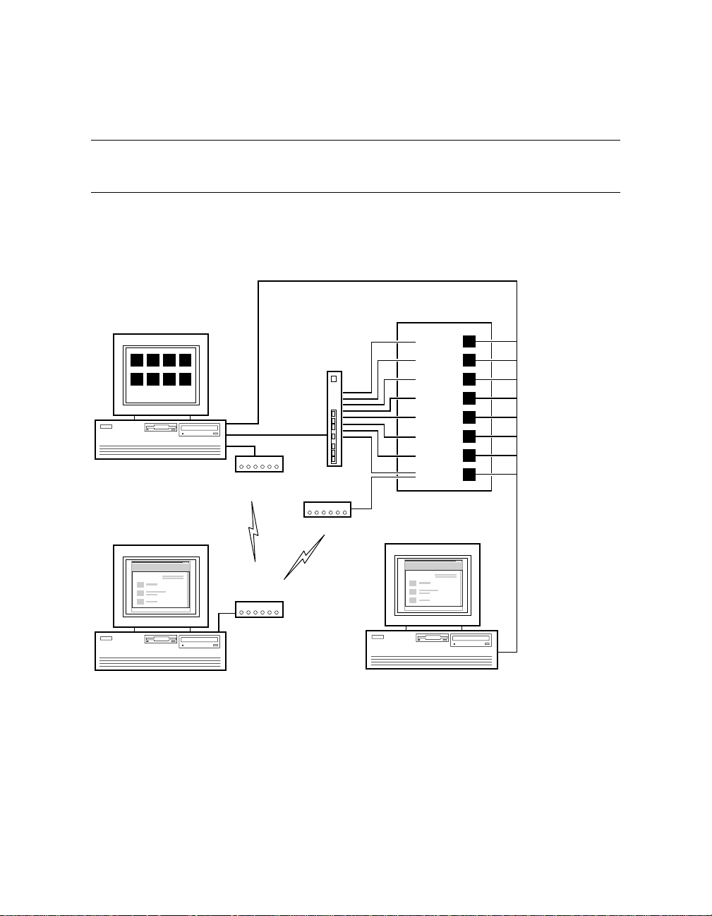
The system management console makes it possible to operate a system
that has multiple partitions with a single console device.
Figure 1–1 System Management Console
Corporate Network
ConsoleWorks Screens
(one for each partition)
3210
7654
System Management
Console PC
COMPAQ
Remote Service PC
Modem
Modem
Private
LAN
Terminal
Server
Modem
System
Initiated
Call
GS320 with
8 Partitions
Partition
Partition
Partition
Partition
Partition
Partition
Partition
Partition
7
6
5
4
3
2
1
0
To Master SCM
COMPAQ
PC on Corporate Network
PK-2702-00
1-2 SMC Installation and User's Guide
Page 23

With the system management console (SMC), an AlphaServer GS80/160/320
system with multiple console linescan be managed from a single device. The
system management console consists of a DECserver 90M terminal server, a
Compaq Deskpro PC, and associated hardware and software. Figure 1–1 shows
a typical system.
The eight-port terminal server can connect to a maximum of eight partitions.
The console for each partition can be displayed in a terminal window under
ConsoleWorks.
The PC contains two network interfaces. The first connects to the terminal
servervia a private LAN. The second connects to the corporate network,
enabling remote operation of the system management console through a Web
browser.
The PC also has an attached modem,which can provide Compaq Services
remote access to the GS80/160/320 system.
1
ConsoleWorks
provides a sophisticated console management environment for
accessing the console of each partition, logging console line activity, and sending
notification of console or system events. In additionto local access through the
SMC, console lines can be accessed from any networked workstation by using a
Web browser.
NOTE: The PC that is supplied as part of the system management console is
supported by Compaq only with thehardware and software
configuration provided. To maintain this support, you maynot add or
replaceany components except as providedby Compaq.
1
The version of ConsoleWorks used on the SMChas been modified by the manufacturer,
TECSys Development Incorporated (TDI), to comply with the AlphaServerManagement
Architecture. TDI’s standardversionof ConsoleWorks cannot be used as a replacement
for this SMC application.
Overview 1-3
Page 24

1.2 How to Use This Manual
The chapters and appendixes in this manual provide instructions for
installing and using the system management console and for restoring
the SMC disk.
Installing the system management console – In Part 2 of this manual,
Chapters 3 through 6 provide procedures for cablingand configuring the system
management console.
• System with multiple consoles – If the system is partitioned, follow the
procedures in Chapters3, 5 (except Section 5.7), and 6.
• System with one console – Follow the procedures in Chapters 4, 5
(Sections 5.1 through 5.4 and 5.7 only), and 6.
Using the system management console – In Part 3, Chapters 7 through 10
provide information on using the system management console.
Troubleshooting – In Part 4, Chapter 11 pro videsbasic troubleshooting
information.
In addition, five appendixes contain additional information about the system
management console.
1-4 SMC Installation and User's Guide
Page 25

Part 2
Installing the
System Management Console
Page 26

Page 27

Chapter 2
Before You Begin
This chapter contains information you need before starting the installation.
Sections in this chapter are:
• Installation Kit
• Installation Sequence
Before You Begin 2-1
Page 28

2.1 Installation Kit
The system management console consists of the SMC PC kit and the
terminal server kit. Typically the terminal server kit is installed at the
factory.
Table 2–1 SMC PC Kit
Part Number Description
3X–DS8BA–xx BOM for SMC PC kit; contains these items:
See note
3R–A1605–xx Power cord and adapter for modem
3R–A1611–AA
NOTE: The PC provided in this kit is the only onethat works in this
configuration. See the 3X–DS8BA–xx BOM for the PC part number.
Compaq Deskpro PC (minitower or desktopbox)
including keyboard, mouse, and Windows NT 4.0 CD
Worldwide V.90/56K external serial modem (includes
PC-to-modem cable)
GS80/160/320 SMC software and documentation:QB–6K4AA–SA
AG–RMDRB–BE, console management software
CD
AV–RMDQB–TE, SMC Installation and Release
Notes
QM–6K4AA–AA, license
EK–GSCON–IN, SMC Installation and User’s
Guide (this manual)
2-2 SMC Installation and User's Guide
Page 29

The order number for the SMC PCkit is 3X–DS8BA–xx. It contains the
components listed in Table 2–1. (The monitor is separately ordered; it is not
part of the SMC PC kit.) The components of the SMC PC kit are installed at the
site.
When the SMC is ordered with the GS80/160/320 system, the terminal server
and cables are installed in the GS160/320 power cabinet or the GS80 cabinet at
the factory. When the SMC is not ordered with the GS80/160/320 system, the
terminal server kit is installed at the site. (Installation instructions are in
Appendix B for GS160/320 systems and Appendix C for GS80 systems.) The
order numberfor the terminal server kit is 3X–DS8AA–AA. Components of the
kit are listed in Table 2–2.
Table 2–2 3X–DS8AA–AA Terminal Server Kit
Quantity Item Description
1 DECserver 90M Terminal server
4 BN25G–04 4-meter cable
4 BN25G–07 7-meter cable
1 BN24Q–07 7-meter crossover cable
8 H8585–AA Connector
Mounting hardware
Before You Begin 2-3
Page 30

2.2 Installation Sequence
Before installing the terminal server, check that the keyswitch and all
AC input box breakers on the GS80/160/320 system are turned to Off.
The following is the recommended sequence of installation for the GS80/160/320
systemand the system management console:
1. Set up the GS80/160/320 hardware. See the AlphaServer GS80 Installation
Guide or the AlphaServer GS160/320 Installation Guide.
2. Set up the SMC PC and, with the GS80/160/320 keyswitch turned to Off,
turn on the breakers on the GS80/160/320 system cabinets and I/O cabinets
(Section 3.1 or Section 4.1).
3. Make the SMC cable connections (Sections 3.2 through 3.4 or Sections 4.2
and 4.3).
4. Configurethe SMC software and verify communication from the system
management console to the system control manager (Chapter 5).
5. Optionally, configure the SMC for remote use (Chapter 6)
6. Power up the GS80/160/320 system (Chapter 6).
2-4 SMC Installation and User's Guide
Page 31

Chapter 3
Connecting the SMC in a System with
Multiple Serial Console Lines
A system with multiple console lines is a GS80/160/320 system that has more
than one standard I/O (SIO) module.The SIO module is in a PCI box connected
to a quad building block, and on it is the SRM console firmware, which provides
a command-line i nterface for operator control of the system or a partition.
Sections in this chapter are:
• Set Up the SMC
• Cable the Terminal Server to the SMC
• Cable the Terminal Server to the GS80/160/320
• MaketheCableConnection
• Record the Connections
• Dress the Cables
• Cable the SMC to the Corporate Network
Connecting the SMC in a System with Multiple Serial Console Lines 3-1
Page 32

3.1 Set Up the SMC
Follow the instructions enclosed with the SMC system and monitor to
set them up, then start the system. With the GS80/160/320 keyswitch
turned off, turn on the AC input box breakers. Make cable connections.
Log on to the SMC system.
Figure 3–1 GS80/160/320 Keyswitch
3
PK-2737-00
Figure 3–2 Windows NT Security Window
3-2 SMC Installation and User’s Guide
Page 33

1. Set up the Compaq Deskpro computer and monitor according to the
accompanyinginstructions.
2. Start the SMC system. As the system software loads, enter information
when requested: user name, company name, product ID, and system name.
See the AlphaServer GS80/160/320 System Management Console
Installation and Release Notes for instructions.
3. Check that the keyswitch on the GS80/160/320 system is turned to Off (
Figure 3–1 points to the Off position) and then turn on the circuit breakers
on the AC input boxes. The breakers are accessible from the rear of both the
GS80 cabinet and the GS160/320 power cabinet. Then make the cable
connections described in Sections 3.2 through 3.4.
4. When the operating system software has finished loading, log on to the SMC
system using the administrator account. (The username is administrator;
for the password, press the Enter key.)
5. Optionally, change the password for the administrator account.
a. Press Ctrl+Alt+Del. The Windows NT Security window displays (Figure
3–2).
b. Click the Change Password… button. The Change Password dialog box
displays.
c. Enter the old password and the new one, and confirm the new password.
Click OK.
6. Check the version of the SMC software by double-clicking the Version icon:
If the version is not 3.1, or if the desktopdoes not have a Versionicon,
update the software. Refer to the AlphaServer GS80/160/320 System
Management Console Installation and Release Notes for instructions.
in
Connecting the SMC in a System with Multiple Serial Console Lines 3-3
Page 34

3.2 Cable the Terminal Server to the SMC
Connect the management channel connector on the terminal server to
network adapter 2 on the SMC system.
Figure 3–3 Terminal Server Management Channel Connector
1
PK-1769-00
1. Connect one end of the BN24Q–07 cable (17–04308–05) to the management
channel connector on the terminal server (
2. Connect the other end of the cable to network adapter 2 on the SMC system
(Figure 3–4). The network adapters are numbered from left to right on the
minitower; bottom to top on the desktop.
NOTE: BN24Q is a crossover cable that can be used only for a point-to-point
Ethernetconnection. It cannot connect an Ethernet node to a hub. If
such a connection is required, use a BN25G cable (17–03212–xx).
3-4 SMC Installation and User’s Guide
in Figure 3–3).
Page 35
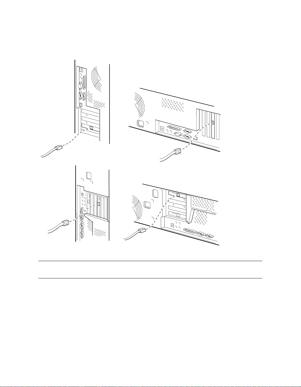
Figure 3–4 Network Adapter 2
Minitower
Model DPENCM
Minitower
Model DPENM
Desktop Box
Model DPENL
Desktop Box
Model DPEND
PK-1723-00
NOTE: The model type is on a label on the top or side of the SMC box.
Connecting the SMC in a System with Multiple Serial Console Lines 3-5
Page 36

3.3 Cable the Terminal Server to the GS80/160/320
For PCI boxes in an expander cabinet, make the cable connection to
the terminal server. Then record the connections in the table provided
and dress the cables.
3.3.1 Make the Cable Connection
Cable the local port of the PCI box to the appropriate port on the
terminal server with a BN25G cable.
Figure 3–5 Local Port Location
1
PK-1724-00
The cable connections are made atthe factory from the standard I/O modules in
PCI boxes in the GS160/320 power cabinet and in the GS80 cabinet. For PCI
boxes in expander cabinets, an H8585–AA connector (12–36054–01) is installed
on the local port (
and attached at the factory.
Make the connection to each console (PCI box with a standard I/O module) in an
expander cabinet. Follow the cabling chart in Table 3–1, and attach the BN25G
cabletotheportontheterminalserver(
Table 3–1 shows the suggested cabling for master PCI boxes only. This
numbering matches the default SMC setup. Secondary boxes (if thereare any)
can be cabled to unused terminalserver ports.
3-6 SMC Installation and User’s Guide
in Figure 3–5) and a BN25G cable (17–03212–05) is labeled
in Figure 3–6).
Page 37

For information about partitioning the system, see AlphaServer GS80/160/320
Getting Started with Partitions.
Table 3–1 Terminal Server Cabling
Terminal Server
Port
GS80 GS160 GS320
1000
2111
3—22
4—33
5——4
6——5
7——6
8——7
Figure 3–6 Terminal Server Ports
QBB Number
1
PK-1770-00
Connecting the SMC in a System with Multiple Serial Console Lines 3-7
Page 38

3.3.2 Record the Connections
Record the connections made for this installation in Table 3–2.
Table 3–2 Terminal Server Cabling at This Installation
Terminal Server Port PCI Box Number QBB Number
1
2
3
4
5
6
7
8
3-8 SMC Installation and User’s Guide
Page 39

3.3.3 Dress the Cables
Form a service loop and tie wrap theBN25G cable to the rail.
Figure 3–7 Terminal Server Cable
2
3
1
8
7
6
5
4
3
2
1
PK-1753-00
1. At the PCI box end, tie wrap the BN25G cable (17–03212–05) to the CSB
junction cable (17–04936–xx) to form a service loop (
2. Tie wrap the BN25G cable down the rail of the expander cabinet (
in Figure 3–7).
).
3. At the bottom of the rail, coil the BN25G cable and place the extra length in
the rail (
).
Connecting the SMC in a System with Multiple Serial Console Lines 3-9
Page 40
3.4 Cable the SMC to the Corporate Network
Connect to the corporate network from network adapter 1 on the SMC
system.
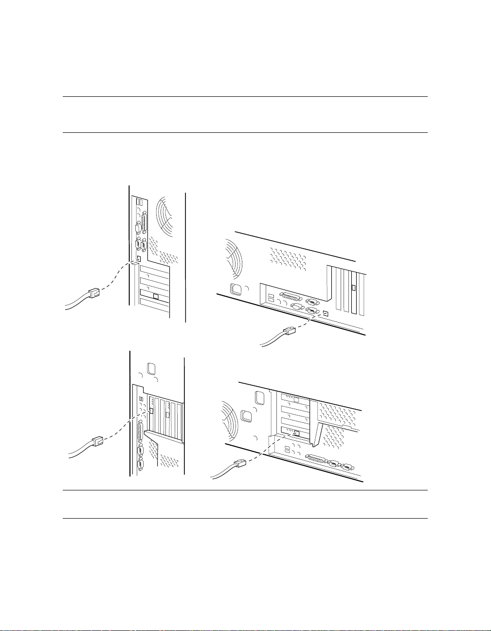
Figure 3–8 Network Adapter 1
Minitower
Model DPENCM
Minitower
Model DPENM
Desktop Box
Model DPENL
Desktop Box
Model DPEND
PK-1727-00
NOTE: The model type is on a label on the top or side of the SMC box.
3-10 SMC Installation and User’s Guide
Page 41

Connect a network cable to network adapter 1 on the SMC system, as shown in
Figure 3–8. (This cable is not included in the SMC installation kit.) The network
adapters are numbered from left to right on the minitower and from bottom to
top on the desktop.
Connecting the SMC in a System with Multiple Serial Console Lines 3-11
Page 42

Page 43

Chapter 4
Connecting the SMC in a System with
One Serial Console Line
A system with a single console line is a GS80/160/320 system that has only one
standard I/O (SIO) module. The SIO module is in a PCI boxconnected to a quad
building block, and on it is the SRM console firmware, which provides a
command-line interface for operator control of the system.
Sections in this chapter include:
• Set Up the SMC
• Cable the SMC to the GS80/160/320
• Cable the SMC to the Corporate Network
• Check the COM1
Connecting the SMC in a System with One Serial Console Line 4-1
Page 44

4.1 Set Up the SMC
Follow the instructions enclosed with the SMC system and monitor to
set them up, then start the system. With the GS80/160/320 keyswitch
turned off, turn on the AC input box breakers. Make cable connections.
Log on to the SMC system.
Figure 4–1 GS80/160/320 Keyswitch
3
PK-2737-00
Figure 4–2 Windows NT Security Window
4-2 SMC Installation and User's Guide
Page 45

1. Set up the Compaq Deskpro computer and monitor according to the
accompanyinginstructions.
2. Start the SMC system. As the system software loads, enter information
when requested: user name, company name, product ID, and system name.
See the AlphaServer GS80/160/320 System Management Console
Installation and Release Notes for instructions.
3. Check that the keyswitch on the GS80/160/320 system is turned to Off (
Figure 4–1 points to the Off position) and then turn on the breakers on the
AC input boxes. The breakers are accessible from the rear of both the GS80
cabinet and the GS160/320 power cabinet. Then make the cable connection
described in Section 4.2.
4. When the operating system software has finished loading, log on to the SMC
systemusing the administrator account.(For the password,press the Enter
key.)
5. Optionally, change the password for the administrator account.
a. Press Ctrl+Alt+Del. The Windows NT Security window displays (Figure
4–2).
b. Click the Change Password… button. The Change Password dialog box
displays.
c. Enter the old password and the new one, and confirm the new password.
Click OK.
6. Check the version of the SMC software by double-clicking the Version icon:
If the version is not 3.1, or if the desktopdoes not have a Versionicon,
update the software. Refer to the AlphaServer GS80/160/320 System
Management Console Installation and Release Notes for instructions.
in
Connecting the SMC in a System with One Serial Console Line 4-3
Page 46

4.2 Cable the SMC to the GS80/160/320
Connect the COM1 port of the SMC system to the local port of the
GS80/160/320.
Figure 4–3 COM1 Port
Minitower
Model DPENCM
COM1 (A)
Minitower
Model DPENM
COM1 (A)
Desktop Box
Model DPENL
COM1 (A)
Desktop Box
Model DPEND
COM1 (A)
PK-1735-00
NOTE: The model type is on a label on the top or side of the SMC box.
4-4 SMC Installation and User's Guide
Page 47

Install H8585–AA connectors (12–36054–01) on the COM1 (or A) port of the
SMC system (Figure 4–3) and the local port of the standard I/O module in the
GS80/160/320 system primary PCI box (
in Figure 4–4). Connect these ports
with a BN24Q cable (17–04308–05).
Figure 4–4 Local Port Connection
1
PK-1724-00
Connecting the SMC in a System with One Serial Console Line 4-5
Page 48

4.3 Cable the SMC to the Corporate Network
Connect to the corporate network from the network adapter on the
SMC system.
Figure 4–5 Network Adapter 1
Minitower
Model DPENCM
Minitower
Model DPENM
Desktop Box
Model DPENL
Desktop Box
Model DPEND
PK-1727-00
NOTE: The model type is on a label on the top or side of the SMC box.
4-6 SMC Installation and User's Guide
Page 49

Connect a network cable to network adapter 1 on the SMC system, as shown in
Figure 4–5. (This cable is not included in the SMC installation kit.) The network
adapters are numbered from left to right on the minitower and from bottom to
top on the desktop.
Connecting the SMC in a System with One Serial Console Line 4-7
Page 50

4.4 Check the COM1 Settings
Check that the baud rate for the COM1 port is 9600. Change it if it is set
to any other speed. Check the other COM1 settings.
Figure 4–6 Ports Dialog Box
4-8 SMC Installation and User's Guide
Page 51

1. From the Start button select Settings|Control Panel.
2. In the control panel, double-click the Ports icon. The Ports dialog box
displays (Figure 4–6).
3. Select COM1 and click the Settings… button. The Settings for COM1 dialog
box displays (Figure 4–7).
4. If the baud rate displayed is not 9600, change it to 9600. Set the Data Bits
to 8, Parity to None, Stop Bits to 1, and Flow Control to XON/XOFF. If these
settings are notcompatiblewith your environment, change them to settings
that are.
Figure 4–7 Settings for COM1 Dialog Box
Connecting the SMC in a System with One Serial Console Line 4-9
Page 52

Page 53

Chapter 5
Configuring the SMC Software
The softwareto be configured depends on the number of consoles in the system.
These sections apply to all systems:
• Set the SMCSystemTime, Date, and Time Zone
• Configurethe NetworkConnections
• Enter the Mail Server Name in the ConsoleWorks Script
• ConfigureOutlook Express
• Delete Unused Consoles in ConsoleWorks
These se ctions apply only to systems that have multiple consoles:
• C onfigure the Terminal Server: Access Server Loader
• Configurethe Terminal Server: AccessServerManager
This section applies only to systems that have a single console:
• Replace the ConsoleWorks ConfigurationFile
NOTE: The GS80/160/320 system should not be powered on at this point. If it
is, power it down by turning the keyswitch on the operator control panel
to Off and turning off the breakers on the AC input boxes.
Configuring the SMC Software 5-1
Page 54

5.1 Set the SMC System Time, Date, and Time Zone
Use the Date/Time icon in the Control Panel to set the time, date, and
time zone.
Figure 5–1 Date & Time Tab
5-2 SMC Installation and User’s Guide
Page 55

1. From the Start button select Settings|Control Panel. The Control Panel
window displays.
2. In the Control Panel double-click the Date/Time icon. The Date/Time
Properties dialog box displays.
3. In the Date & Time tab, set the date and time (Figure 5–1).
4. Select the Time Zone tab (Figure 5–2).
5. From the drop-down menu select the time zone for this installation. Click
OK.
Figure5–2 TimeZoneTab
Configuring the SMC Software 5-3
Page 56

5.2 Configure the Network C onnections
Verify the computer name and the protocol for the private LAN.
Specify the IP address. Finally, set up the adapter for the corporate
network.
5.2.1 Verify the Computer Name
Figure 5–3 Identification Changes Dialog Box
5-4 SMC Installation and User’s Guide
Page 57

1. Open the Windows ControlPanel: From the Start menu select
Settings|Control Panel.
2. Double-click the Network icon. The Network dialog box displays with the
Identification tab selected.
3. Click the Change… button. The IdentificationChanges dialog box displays
(Figure 5–3). Check that the box labeled Computer Name correctly identifies
the SMC system as a management station on the corporatenetwork. (In the
example shown in Figure 5–3, that name is MySMC.) If it does not, enter
the correct name. Click OK.
4. The system can be a member of a workgroup or a domain. (If you are unsure
which it should be, ask the network administrator.) Select the appropriate
option button and enter the workgroup or domain name.
NOTE: The computer name entered in step 3 cannot be GSSMC1. This nameis
reserved for the terminal server.
Configuring the SMC Software 5-5
Page 58

5.2.2 Verify the Network Protocol
Figure 5–4 Network Dialog Box
5-6 SMC Installation and User’s Guide
Page 59

1. In the Network dialog box, select the Protocols tab (Figure 5–4). If the
protocol shown is TCP/IP, skip the rest of this page and go on to Section
5.2.3.
2. If the protocol shown is not TCP/IP, highlight the protocol and click the
Remove button. A message box displays; click Yes.
3. In the Network dialog box, click the Add… button. The Select Network
Protocol dialog box displays (Figure 5–5). Highlight TCP/IP Protocol. Click
OK. A box displays with a message that begins “If there is a DHCP server
on your network….” Click No.
4. The Windows NT Setup dialog box displays. Click Continue.
Figure 5–5 Select Network Protocol Dialog Box
Configuring the SMC Software 5-7
Page 60

5.2.3 Configure Network Adapter 1
Figure 5–6 Microsoft TCP/IP Properties
NOTE: The IP address values in the illustration are an example only. Obtain
the correct values for this installation from thenetwork administrator.
5-8 SMC Installation and User’s Guide
Page 61

Enter the static IP address, subnet mask, and gateway. Ask the network
administrator for this information. The SMC requires a static IP address; it
cannot have a dynamic address (that is, an address assigned by a DHCP
server).
1. In the Adapter box of the Microsoft TCP/IP Properties dialog box (Figure 5–
6), select adapter 1.
2. Select the option button labeled Specify an IP address. Enter the IP address,
subnet mask, and gateway. Click OK.
NOTE: The network card shown in Figure 5–6 is an example only. Another type
of network card might be supplied.
Configuring the SMC Software 5-9
Page 62

5.2.4 Configure Network Adapter 2
Figure 5–7 Microsoft TCP/IP Properties Dialog Box
5-10 SMC Installation and User’s Guide
Page 63

1. In the Network dialog box, select the Protocols tab. Click the Properties
button.
2. The Microsoft TCP/IP Properties dialog box displays (Figure 5–7). Select
adapter 2.
3. Select the option button labeled Specify an IP address. Enter the following
information:
IP address: 90.0.0.100
Subnet mask: 255.255.255.0
Leave the Default Gateway blank. Click OK.
NOTE: The network card shown in Figure 5–7 is an example only. Another type
of networkcard might be used.
Configuring the SMC Software 5-11
Page 64
5.2.5 Bind the Protocol
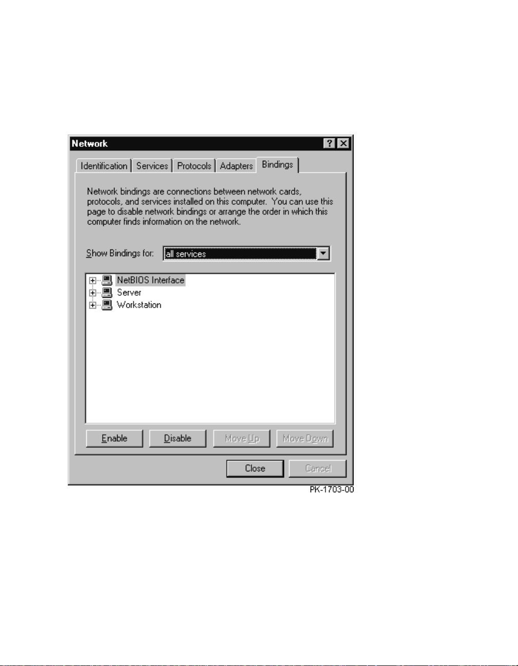
Figure 5–8 Bindings Tab in the Network Dialog Box
1. In the Network dialog box, select the Bindings tab. A box with a progress
bar displays.
2. When the progress bar indicates that the operation is finished, click Close.
3. Restart the SMC system.
5-12 SMC Installation and User’s Guide
Page 65

5.2.6 Verify the Network Setup
Figure 5–9 Verifying the Network Setup
1. Open a Command window: From the Start menu select Programs|
Command Prompt.
2. At the prompt type ping 90.0.0.100. The response should look similar to
the first command in Figure 5–9.
3. At the prompt type ping name,wherename is the fully qualified computer
name displayedin Section 5.2.1. The response should look similar to the
second command in Figure 5–9.
Configuring the SMC Software 5-13
Page 66

5.3 Enter the Mail Server Name in the ConsoleWorks
Script
ModifythefileMAIL.PLtoincludethenameofthemailserver.This
file is in the folder C:\Cwks\Actions\Event.
Example 5–1 Modifying the ConsoleWorks Script (MAIL.PL)
#!/usr/local/bin/perl
# Note: This is written in a very simple version of Perl for
# non-experts)
# In perl, a single character match is the period ".",
# contrasting with "%" in ConsoleWorks.
# Multi is "*" in both cases.
# Also for WinNT, you can not start a perl file directly,
# though you can in a command window
# Therefore create a single line script MAIL.BAT like this
# C:\Perl\Bin\Perl C:\Cwks\Actions\Event\mail.pl %1 %2 %3 %4
#%5%6
#+
# Before this can be used, please change the $remote = line in
# the smtpmail subroutine
#
# Mail Action Script
#
# $ARGV[0] Console name
# $ARGV[1] Event Name
# $ARGV[2] Event Sequence Number
# $ARGV[3] Name of event context file
# $ARGV[4] Contact name(s), comma delimited
# $ARGV[5] User Supplied Paramter
#use Socket;
sub smtpmail {
my ($to, $subj, $whoami, $mf, @msg) = @_;
my ($port, $iaddr, $paddr, $proto, $line);
# This is site specific
$remote = "my.email.server.name.net";
.
.
.
if ($domail) {
5-14 SMC Installation and User’s Guide
Page 67

Modify the file MAIL.PL to include the name of the mail server. This file is in
the folder C:\Cwks\Actions\Event.
1. Open MAIL.PL in Notepad or anoth er text editor.
2. Find the line ‘$remote = “my.email.server.name.net”;’ (
The example shows an excerpt from the file; for a full listing of MAIL.PL,
see AppendixD.)
3. Obtain the name of the mail server from the network administrator.
Replace everything between the double quotes with the server name.
4. Save the file and close the editor.
in Example 5–1.
Configuring the SMC Software 5-15
Page 68

5.4 Configure Outlook Express
Obtain mail server information from the network administrator before
configuring.
Figure 5–10 Internet Accounts Dialog Box
1. Double-click the Outlook Express icon on the desktop. If this is the first time
Outlook Express is opened, a box displays asking where messages should be
stored. Select a folder and click OK. The Outlook Express window displays.
2. From the Tools menu select Accounts. The Internet Accounts dialog box
displays (Figure 5–10).
3. Select the Mail tab and click the Add button. In the fly-out menu select
Mail….The InternetConnectionWizard displays.
4. The wizard asks for the following information; obtain it from the network
administrator:
a. The address of the e-mail account that will send and receive mail on the
SMC.
5-16 SMC Installation and User’s Guide
Page 69

b. The type of server for incoming mail. Outlook Express recognizes POP3
and IMAP.
c. The names of the incoming and outgoing mail servers.
5. When Outlook Express sends or receives mail, by default it removes the
messages from the server. To leave a copy of messages on the server, do the
following:
a. From the Tools menu select Accounts.In the Internet Accounts window
right-click on the account name and select Properties from the pop-up
menu. The account_name Properties dialog box displays (Figure 5–11).
b. Select the Advanced tab. In the section labeled Delivery select the
checkbox labeled Leave a copy of messages on server.
Figure 5–11 account_name Properties Dialog Box
Configuring the SMC Software 5-17
Page 70

5.5 Delete Unused Consoles in ConsoleWorks
Start and log on to ConsoleWorks. Select Consoles and Delete Console.
Figure 5–12 ConsoleWorks Delete Console Screen
5-18 SMC Installation and User’s Guide
Page 71

The defaultconfiguration for ConsoleWorks is eight consoles. If the
GS80/160/320 system has fewer than eight consoles (that is, fewer than eight
PCI boxes with standard I/O modules that are connected to the terminal server),
delete the extras in ConsoleWorks.
NOTE: Unused consoles generatea great number of events, causing the log files
and the file DEFAULT.CONFIG to grow to an unmanageable size and
slow down the system. Deleting unused consoles is strongly
recommended.
1. Start and log on to ConsoleWorks (Section 8.1).
2. In the left navigation panel of the ConsoleWorks window select Consoles.
The Show Consoles screen displays.
3. At the top of the Show Consoles screen select Delete Console. The Delete
Console screen displays (Figure 5–12).
4. From the Delete dropdown menu select the console to be deleted.
5. Click the Delete Console button. A verification message displays (Figure 5–
13).
6. Click OK to delete the console. The Show Consoles screen displays; the
deleted console is no longer listed.
Figure 5–13 Delete Console Verification Message
Configuring the SMC Software 5-19
Page 72

5.6 Configure the Terminal Server: Access Server
Loader
Access Server Loader configures the IP address and subnet mask of the
terminal server.
5.6.1 Open Access Server Loader
Figure 5–14 Access Server Loader Window
5-20 SMC Installation and User’s Guide
Page 73

1. Start Access Server Loader: From the Start menu select Programs|Access
Server Loader|Access Server Loader. The Access Server Loader window
displays (Figure 5–14).
2. Click Setup. The Confirm dialog box displays (Figure 5–15). Click Yes.
Figure 5–15 Access Server Loader Confirm Dialog Box
Configuring the SMC Software 5-21
Page 74

5.6.2 Create the Database
Figure 5–16 Access Server Loader Configuration Dialog Box
5-22 SMC Installation and User’s Guide
Page 75

1. The Access Server Loader Configuration dialog box displays (Figure 5–16).
On the Clients tab, enter the following information:
Host Name: computer name (Section 5.2.1)
Hardware Addr: from thelabelon the terminal server (
in Figure 5–17)
IP Addr: 90.0.0.1
Subnet Mask: 255.255.255.0
NOTE: The IP address you enter in the Access Server Loader Configuration
dialog box is theIP address for the terminalserver, not for the host.
2. Click OK. The Access Server Loader window displays.
Figure 5–17 Location of Hardware Address Label
0
C
-
7
5
-
3
9
-
D
6
-
0
6
-
0
0
1
PK-1783-00
Configuring the SMC Software 5-23
Page 76

5.6.3 Verify the Connection
Figure 5–18 Access Server Loader Window
Figure 5–19 Verifying the Connection
5-24 SMC Installation and User’s Guide
Page 77

1. Keeping the GS80/160/320 keyswitch in the Off position, turn on the
breakers on the AC input boxes.
NOTE: Turning on the breakers applies power to the terminal server. These
instructions assume that the terminal server has not been powered
on until now. If it was on when you reached this point, power cycle
the terminal server now.
2. Check the Access Server Loader window (Figure 5–18) for the following:
a. The indicators on theBOOTPServer On/Off button and the TFTP
Server On/Off button should display green. If an indicator displays red,
click the button.
b. The hardware address after Reply in the BOOTP Server block should
match the hardware address label on the terminal server. If it has been
at least one minute since you turned on theAC input box breakers and
the addresses do not match, do the following:
1. Check that the terminal server has power (Section B.4 or C.4).
2. Check that the cable from the terminal server to the SMC system is
connected correctly (Section 3.4).
3. Check that the position identifier dial on the terminal server is set
correctly (Section B.3 or C.3).
If, after performing these three checks, you find that the Request
address is still different from the hardware address on the terminal
server label,refer to the terminal serverdocumentation.
3. Click the Close button to close Access Server Loader.
4. Verify the connection.
a. Open a Command window: From the Start menu select
Programs|Command Prompt.
b. At the prompt, type ping 90.0.0.1. The response should be similar to
Figure 5–19.
c. Close the Commandwindow.
Configuring the SMC Software 5-25
Page 78

5.7 Configure the Terminal Server: Access Server
Manager
Access Server Manager configures the terminal server for access by the
SMC system.
5.7.1 Open Access Server Manager
Figure 5–20 New Access Server Window
5-26 SMC Installation and User’s Guide
Page 79

1. Start Access ServerManager. From the Start menu select Programs|
Access Server Manager|Access ServerManager. The Access Server
Manager window displays.
2. From the File menu select New. The New Access Server dialog box displays
(Figure 5–20). The default Login Password is access and the default
Privileged Password is system. Click OK.
3. The Access Server dialog box displays (Figure 5–21).
Figure 5–21 Access Server Dialog Box
Configuring the SMC Software 5-27
Page 80

5.7.2 Test the Connection
Figure 5–22 Access Server Dialog Box, Utilities Tab
5-28 SMC Installation and User’s Guide
Page 81

1. In the Access Server dialog box, select the Utilities tab (Figure 5–22). Select
Test Connection. Click the Do It Now… button. The message “Access Server
connection test successful” displays. Click OK.
2. Select Connect to Telnet Console. Click the Do It Now… button. The Telnet
window displays (Figure 5–23).
3. At the Local> prompt type show server. A snapshot of the server displays.
This confirms the connection.
4. Close the Telnet window.
Figure 5–23 Telnet Window
Configuring the SMC Software 5-29
Page 82

5.7.3 Configure Access Server Manager
Figure 5–24 Select a Command File Dialog Box
5-30 SMC Installation and User’s Guide
Page 83

1. From the Utilities tab of the Access Server dialog box (Figure 5–22), select
Run Command File.
2. Click the Do It Now… button. The Select a Command File dialog box
displays (Figure 5–24).
3. Select the file GS_CON.cmds. Click Open. The Run Command File dialog
box displays (Figure 5–25). Click OK. The command file runs.
4. Close the Access Server dialog box and return to Access Server Manager.
5. Close Access ServerManager.
Figure 5–25 Run Command File Dialog Box
Configuring the SMC Software 5-31
Page 84

5.8 Replace the ConsoleWorks Configuration File
The default configuration file put in place by the SMC installation
process is for multiple-console systems. If this system has only one
console, replace the configuration file.
Figure 5–26 Configuration Files Folder
5-32 SMC Installation and User’s Guide
Page 85

1. In Windows Explorer go to the folder C:\Cwks\Config (Figure 5–26).
2. Copy the file SERIAL_COM1_DEFAULT.CONFIG:
a. Click on the file to highlight it.
b. From the Edit menu select Copy.
3. From the Edit menu select Paste. A file named Copy of
SERIAL_COM1_DEFAULT.CONFIG is pasted into the folder.
4. Delete the file DEFAULT.CONFIG.
5. Rename the file Copy of SERIAL_COM1_DEFAULT.CONFIG to
DEFAULT.CONFIG:
a. Click on the file to highlight it.
b. From the File menu select Rename.
c. In the highlighted name enter DEFAULT.CONFIG.
Configuring the SMC Software 5-33
Page 86

Page 87

Chapter 6
Configuring the SMC for Remote Use
Sections in this chapter are:
• Set Up the Modem
• Configurethe Remote Access Software
NOTE: When you have finished setting up the modem and configuring the
remote accesssoftware, restart the SMC system and set the keyswitch on
the GS80/160/320 to On.
Configuring the SMC for Remote Use 6-1
Page 88

6.1 Set Up the Modem
Follow the manufacturer’s instructions for cabling the modem.
Figure 6–1 COM2 Port
Minitower
Model DPENCM
COM2 (B)
Minitower
Model DPENM
COM2 (B)
Desktop Box
Model DPENL
Desktop Box
Model DPEND
COM2 (B)
COM2 (B)
PK-1735A-00
NOTE: The model type is on a label on the top or side of the SMC box.
1. Cable the modem, following the manufacturer’sinstructions. Connect the
RS-232C cable from the SMC installation kit to COM2 on the SMC system
(Figure 6–1; COM2 might be marked B).
6-2 SMC Installation and User's Guide
Page 89

2. Open the Control Panel: From the Start menu select Settings|Control
Panel.
3. Double-click the Modems icon. The Install New Modem dialog box displays.
Click Next. The operating system detects the modem and tests it.
4. The Install New Modem dialog box displays, with the words Standard
Modem in the box. Click the Change… button. Click the Have Disk…
button.Insert the disk that came with the modemin the appropriate drive.
5. In the dialog box click the Browse button, and select the drive and file.
Select the modem type.
6. Check that the Modem Properties box (Figure 6–2) displays, indicating that
the modem has installed correctly.
Figure 6–2 Modem Detected
Configuring the SMC for Remote Use 6-3
Page 90
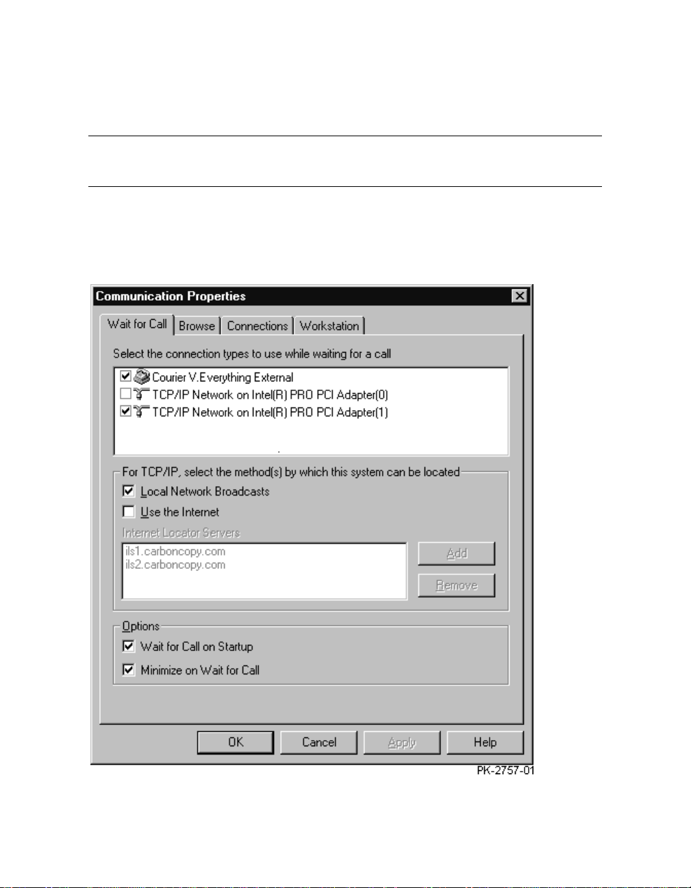
6.2 Configure the Remote Access Software
Configure both remote access applications, Carbon Copy Access
Edition and WinVNC.
6.2.1 Carbon Copy Access Edition
Figure 6–3 Communication Properties Dialog Box
6-4 SMC Installation and User's Guide
Page 91

1. Start Carbon Copy Access Edition: From the Start menu select
Programs|Carbon Copy Access Edition|Carbon Copy.
2. From the Options menu select Communications. The Communication
Properties dialog box displays (Figure 6–3).
NOTE: Check with the customer beforesettingup the Waitfor Call feature.
3. In the tab labeled Wait for Call, select the modem and the corporate
network in the box labeledSelect the connection types. In theOptions block,
select Wait for Call on Startup. Click OK.
4. In the Carbon Copy Access Edition window (Figure 6–4), click the Wait for
Call button. If you selected Minimize on Wait for Call in the Communication
Properties dialog box, the program now minimizes.
Figure 6–4 Carbon Copy Access Edition Window
Configuring the SMC for Remote Use 6-5
Page 92

6.2.2 WinVNC
Figure 6–5 Default Local System Properties Dialog Box
1. Display the WinVNC settings: from the Start menu select Programs|
VNC|Administrative Tools|Show Default Settings.The Default Local
System Properties dialog box displays (Figure 6–5).
2. Enter a password and select the checkboxes shown in Figure 6–5.
6-6 SMC Installation and User's Guide
Page 93

Part 3
Using the
System Management Console
Page 94

Page 95

System Management Console
Sections in this chapter are:
• Logging on to the SMC
• Using the SMC Locally
• Using the SMC Remotely
• Keep in Mind
Chapter 7
Getting Started with the
GettingStarted with the System Management Console 7-1
Page 96

7.1 Logging on to the SMC
Logon is automatic if the administrator account has no password. For
manual logon, a different account can be used, or the administrator
account can be given a password.
Figure 7–1 Windows NT Security Window
The SMC system is configured to log on to the administrator account
automatically when it powers up. If you leave the administrator account with
the default configuration (that is, without a password), you can log on to
another account by following these instructions.
1. Close all applications.
2. Press Ctrl+Alt+Del. The Windows NT Securitywindow displays(Figure 7–
1).
3. Click Logoff… . A window displayswith the message “This will end your
Windows NT session.”
4. Click OK and immediately depress and hold the Shift key. Hold this key
until the Log On dialog box displays.
5. Enter a username and passwordthatare valid for this system. Click OK.
7-2 SMC Installation and User's Guide
Page 97

If the administrator account is reconfigured to use a password, the Log On
dialog box always displayswhen the PC powers up. You cangive that account a
password by following these instructions.
1. Press Ctrl+Alt+Del. The Windows NT Securitywindow displays(Figure 7–
1).
2. Click Change Password… The Change Password dialog box displays(Figure
7–2).
3. Enter the old password and the new one, and enter the new password again
to confirm it. (The passwords display as asterisks.) Click OK.
Figure 7–2 Change Password Dialog Box
GettingStarted with the System Management Console 7-3
Page 98

7.2 Using the SMC Locally
Icons on the SMC desktop are used to run applications locally.
Figure 7–3 SMC Desktop
The SMC desktop has several icons that enable you to run applications and
view documentation online. Table 7–1 shows the icons and describes the result
of double-clicking each.
7-4 SMC Installation and User's Guide
Page 99

Table 7–1 SMC Desktop Icons
Icon Function
Runs ConsoleWorks, the console management application used
by the SMC. SeeChapter 8 for a quick reference and the
ConsoleWorks Administration/User Guide for more i n-depth
information.
NOTE: Since ConsoleWorksruns in the Internet Explorer
browser, the first time you start it, the Internet Explorer
Setup Wizard runs. You will need to supplyconnection
information, including proxies if applicable.
Runs Compaq AlphaServer Partition Manager (CAPM), an
application that simplifies the creation of partitions on the
GS80/160/320 system. Chapter 9 describes this application.
Displays a PDF file of the AlphaServer GS80/160/320 System
Management Console Installation and User’s Guide (this
manual). PDF files are viewed online and can be printed.
Displays a PDF file of the ConsoleWorks Administration/User
Guide.
Displays version informationfor the SMC release and all
software distributed on the SMC software CD.
Opens the SMC Web page (see Section 7.3).
GettingStarted with the System Management Console 7-5
Page 100

7.3 Using the SMC Remotely
The SMC Web page is used to run applications remotely.
Figure 7–4 SMC Web Page
7-6 SMC Installation and User's Guide
 Loading...