

Page 1

AlphaServer GS80/160/320
User’s Guide
Order Number: EK-GS320-UG. C01
This guide is intended for those who manage, operate, or service the
AlphaServer GS160/320 system and the AlphaServer GS80 rack
system. It covers configuration guidelines, operation, system
management, and basic troubleshooting.
Compaq Computer Corporation
Page 2

Revised September 2000
© 2000 Compaq Computer Corporation.
COMPAQ, the Compaq logo, and AlphaServer registered in U.S. Patent and Trademark Office. OpenVMS,
StorageWorks, and Tru64 are trademarks of Compaq Information Technologies Group, L.P.
Portions of the software are © copyright Cimetrics Technology. Linux is a registered trademark of Linus
Torvalds in several countries. UNIX is a registered trademark of The Open Group in the U.S. and other
countries. All other product names mentioned herein may be trademarks of their respective companies.
Compaq shall not be liable for technical or editorial errors or omissions contained herein. The information in
this document is subject to change without notice.
FCC Notice
This equipment generates, uses, and may emit radio frequency energy. The equipment has been type tested
and found to comply with the limits for a Class A digital device pursuant to Part 15 of FCC rules, which are
designed to provide reasonable protection against such radio frequency interference.
Operation of this equipment in a residential area may cause interference in which case the user at his own
expense will be required to take whatever measures may be required to correct the interference.
Any modifications to this device—unless expressly approved by the manufacturer—can void the user’s
authority to operate this equipment under part 15 of the FCC rules.
Modifications
The FCC requires the user to be notified that any changes or modifications made to this device that are not
expressly approved by Compaq Computer Corporation may void the user's authority to operate the
equipment.
Cables
Connections to this device must be made with shielded cables with metallic RFI/EMI connector hoods in
order to maintain compliance with FCC Rules and Regulations.
Taiwanese Notice
Page 3

Japanese Notice
Canadian Notice
This Class A digital apparatus meets all requirements of the Canadian Interference-Causing Equipment
Regulations.
Avis Canadien
Cet appareil numérique de la classe A respecte toutes les exigences du Règlement sur le matériel brouilleur
du Canada.
European Union Notice
Products with the CE Marking comply with both the EMC Directive (89/336/EEC) and the Low Voltage
Directive (73/23/EEC) issued by the Commission of the European Community.
Compliance with these directives implies conformity to the following European Norms (in brackets are the
equivalent international standards):
EN55022 (CISPR 22) - Electromagnetic Interference
EN50082-1 (IEC801-2, IEC801-3, IEC801-4) - Electromagnetic Immunity
EN60950 (IEC950) - Product Safety
Achtung!
Dieses ist ein Gerät der Funkstörgrenzwertklasse A. In Wohnbereichen können bei Betrieb dieses Gerätes
Rundfunkstörungen auftreten, in welchen Fällen der Benutzer für entsprechende Gegenmaßnahmen
verantwortlich ist.
Attention!
Ceci est un produit de Classe A. Dans un environnement domestique, ce produit risque de créer des
interférences radioélectriques, il appartiendra alors à l'utilisateur de prendre les mesures spécifiques
appropriées.
Page 4

Page 5

Contents
Preface ........................................................................................................................xi
Chapter 1 Introduction
1.1 AlphaServer GS160/320 and GS80 Systems......................................... 1-2
1.2 Firmware and Utilities Overview ......................................................... 1-4
1.3 System Architecture.............................................................................. 1-5
Chapter 2 GS160/320 System Overview
2.1 System Characteristics ......................................................................... 2-2
2.2 System Box Architecture....................................................................... 2-4
2.3 Quad Building Block (QBB) Components .............................................2-6
2.3.1 Backplane.............................................................................................. 2-8
2.3.2 CPU Module........................................................................................ 2-10
2.3.3 Memory Module .................................................................................. 2-11
2.3.4 Directory Module................................................................................. 2-12
2.3.5 Power Modules.................................................................................... 2-13
2.3.6 Power System Manager Module.......................................................... 2-14
2.3.7 Clock Splitter Module ......................................................................... 2-15
2.3.8 I/O Riser Module ................................................................................. 2-16
2.3.9 Global Port Module ............................................................................. 2-17
2.3.10 Distribution Board........................................................................ 2-18
2.3.11 Hierarchical Switch ...................................................................... 2-20
2.4 Power System...................................................................................... 2-22
2.4.1 AC Input Box....................................................................................... 2-24
2.5 PCI I/O ................................................................................................ 2-26
2.6 Control Panel ...................................................................................... 2-28
2.6.1 Control Panel LEDs ............................................................................ 2-30
v
Page 6

Chapter 3 GS160/320 System Configuration Rules
3.1 GS160 System Cabinet.......................................................................... 3-2
3.2 GS320 System Cabinets........................................................................ 3-4
3.3 Power Cabinet....................................................................................... 3-6
3.3.1 Power Supply Slot Assignments ........................................................... 3-8
3.4 System Box.......................................................................................... 3-10
3.5 QBB Color Code .................................................................................. 3-12
3.6 Memory Configurations ...................................................................... 3-14
3.7 Memory Interleaving Guidelines ........................................................ 3-16
3.8 PCI Boxes............................................................................................ 3-18
3.9 PCI Box Slot Configuration................................................................. 3-20
3.10 Expander Cabinet ............................................................................... 3-22
Chapter 4 GS80 Rack System Overview
4.1 Rack System Characteristics ................................................................ 4-2
4.2 System Drawer Architecture................................................................. 4-4
4.3 System Drawer Modules....................................................................... 4-6
Chapter 5 GS80 Rack System Configuration Rules
5.1 Rack....................................................................................................... 5-2
5.2 Rack Power System............................................................................... 5-4
Chapter 6 Booting and Installing an Operating System
6.1 Powering Up the System....................................................................... 6-2
6.1.1 SCM Power-Up Display ........................................................................ 6-4
6.1.2 SRM Power-Up Display ........................................................................ 6-6
6.2 Setting Boot Options........................................................................... 6-10
6.2.1 Bootdef_dev......................................................................................... 6-10
6.2.2 Boot_file .............................................................................................. 6-11
6.2.3 Boot_osflags......................................................................................... 6-12
6.2.4 ei*0_inet_init or ew*0_inet_init.......................................................... 6-14
6.2.5 ei*0_protocols or ew*0_protocols......................................................... 6-15
6.3 Booting Tru64 UNIX........................................................................... 6-16
6.3.1 Booting Tru64 UNIX Over the Network............................................. 6-18
6.4 Installing Tru64 UNIX........................................................................ 6-20
6.5 Booting OpenVMS............................................................................... 6-22
6.5.1 Booting OpenVMS from the InfoServer.............................................. 6-24
6.6 Installing OpenVMS ........................................................................... 6-26
vi
Page 7

Chapter 7 Operation
7.1 SRM Console ......................................................................................... 7-2
7.1.1 SRM Command Overview..................................................................... 7-4
7.1.2 Setting the Control Panel Message....................................................... 7-6
7.2 Displaying the System Configuration................................................... 7-7
7.2.1 Show Boot Command............................................................................ 7-7
7.2.2 Show Config Command......................................................................... 7-8
7.2.3 Show Device Command....................................................................... 7-16
7.2.4 Show Memory Command .................................................................... 7-18
7.3 Setting SRM Environment Variables ................................................. 7-19
7.4 Setting SRM Console Security ............................................................ 7-20
7.4.1 Setting Tru64 UNIX or OpenVMS Systems to Auto Start ................. 7-21
7.5 Changing the Default Boot Device...................................................... 7-21
7.6 Soft Partitioning.................................................................................. 7-22
7.7 Hard Partitioning................................................................................ 7-26
Chapter 8 Using the System Control Manager
8.1 Console Serial Bus Subsystem.............................................................. 8-2
8.2 System Control Manager Overview...................................................... 8-4
8.3 SCM COM1 Operating Modes............................................................... 8-6
8.3.1 Bypass Modes........................................................................................ 8-8
8.4 Console Device Setup.......................................................................... 8-10
8.5 Entering the SCM ............................................................................... 8-12
8.6 SRM Environment Variables for COM1............................................. 8-13
8.7 SCM Command-Line Interface ........................................................... 8-14
8.7.1 Defining the COM1 Data Flow ........................................................... 8-17
8.7.2 Displaying the System Status............................................................. 8-18
8.7.3 Displaying the System Environment.................................................. 8-20
8.7.4 Power On and Off, Reset, and Halt..................................................... 8-22
8.7.5 Configuring Remote Dial-In................................................................ 8-24
8.7.6 Configuring Alert Dial-Out................................................................. 8-26
8.7.7 Resetting the Escape Sequence........................................................... 8-29
8.8 Troubleshooting Tips........................................................................... 8-30
Appendix A Jumpering Information
A.1 PCI Backplane Jumpers........................................................................A-1
A.2 HPM Jumpers.......................................................................................A-2
A.3 Standard I/O Module Jumpers..............................................................A-2
vii
Page 8

Glossary
Index
Examples
6–1 SCM Power-Up Display ........................................................................ 6-2
6–2 SRM Power-Up Display ........................................................................ 6-6
6–3 Booting Tru64 UNIX from a Local SCSI Disk .................................... 6-16
6–4 RIS Boot .............................................................................................. 6-18
6–5 Tru64 UNIX Installation Display ....................................................... 6-20
6–6 Booting OpenVMS from a Local Disk ................................................. 6-22
6–7 InfoServer Boot................................................................................... 6-24
6–8 OpenVMS Installation Menu.............................................................. 6-26
7–1 Set Ocp_Text Command...................................................................... 7-6
7–2 Show Boot*............................................................................................ 7-7
7–3 Show Config .......................................................................................... 7-8
7–4 Show Device ........................................................................................ 7-16
7–5 Show Memory...................................................................................... 7-18
7–6 Defining Soft Partitions ...................................................................... 7-24
7–7 Defining Hard Partitions .................................................................... 7-26
8–1 Dial-In Configuration.......................................................................... 8-24
8–2 Alert Dial-Out Configuration.............................................................. 8-26
Figures
1–1 AlphaServer GS160 and GS80 Systems................................................ 1-2
1–2 Sample System Architecture................................................................. 1-5
2–1 System Box............................................................................................ 2-2
2–2 System Box Block Diagram (16-Processor System) .............................. 2-4
2–3 System Box Block Diagram (8-Processor System)................................ 2-5
2–4 System Box QBBs (Top View)............................................................... 2-6
2–5 Backplane (System Box, Front View)....................................................2-8
2–6 CPU Module........................................................................................ 2-10
2–7 Memory Module .................................................................................. 2-11
2–8 Directory Module................................................................................. 2-12
2–9 Power Modules.................................................................................... 2-13
2–10 Power System Manager Module.......................................................... 2-14
2–11 Clock Splitter Module ......................................................................... 2-15
2–12 I/O Riser Module ................................................................................. 2-16
viii
Page 9

2–13 Global Port Module ............................................................................. 2-17
2–14 Distribution Board .............................................................................. 2-18
2–15 Distribution Board in Single-Box System ........................................... 2-19
2–16 Hierarchical Switch............................................................................. 2-20
2–17 Power System...................................................................................... 2-22
2–18 AC Input Box....................................................................................... 2-24
2–19 PCI Master Box ................................................................................... 2-26
2–20 Control Panel ...................................................................................... 2-28
2–21 Control Panel LED Status .................................................................. 2-30
3–1 GS160 System....................................................................................... 3-2
3–2 GS320 System....................................................................................... 3-4
3–3 Power Cabinet Configuration (32-P System)........................................ 3-6
3–4 Power Supply Slot Assignments ........................................................... 3-8
3–5 System Box QBB (Cabinet Front)....................................................... 3-10
3–6 System Box QBB (Cabinet Rear) ........................................................ 3-11
3–7 QBB Center Bar Color Code (Cabinet Front)...................................... 3-12
3–8 QBB Center Bar Color Code (Cabinet Rear)....................................... 3-13
3–9 Memory Module and Directory Module .............................................. 3-14
3–10 Sample I/O Subsystem ........................................................................ 3-18
3–11 PCI Slot Locations............................................................................... 3-20
3–12 BA356 Storage Device Configurations................................................ 3-22
4–1 System Drawer...................................................................................... 4-2
4–2 Two-Drawer Block Diagram.................................................................. 4-4
4–3 System Drawer Modules....................................................................... 4-6
4–4 System Drawer Backplane.................................................................... 4-7
5–1 Rack....................................................................................................... 5-2
5–2 Rack Optional Configurations............................................................... 5-3
5–3 Two-Drawer Rack Power System.......................................................... 5-4
8–1 CSB Block Diagram .............................................................................. 8-2
8–2 Data Flow in Through Mode .................................................................8-6
8–3 Data Flow in Bypass Mode.................................................................... 8-8
8–4 Setups for SCM (PCI Box).................................................................. 8-11
Tables
1 AlphaServer 80/160/320 Family Documentation .................................. xiv
2–1 System Box Characteristics .................................................................. 2-2
2–2 Power Cabinet and System Environmental Characteristics ................2-3
2–3 AC Input Box Circuit Breakers........................................................... 2-25
3–1 Interleaving Memory Modules............................................................ 3-16
3–2 PCI Slots and Logical Hoses ............................................................... 3-21
ix
Page 10

4–1 System Drawer Characteristics ............................................................ 4-2
4–2 Rack System Characteristics ................................................................ 4-3
6–1 OpenVMS Boot Flag Settings ............................................................. 6-13
7–1 Summary of SRM Commands............................................................... 7-2
7–2 Notation Formats for SRM Console Commands................................... 7-4
7–3 Special Characters for SRM Console ................................................... 7-5
7–4 Device Naming Conventions............................................................... 7-17
7–5 SRM Environment Variables for Soft Partitions ................................ 7-23
7–6 SCM Environment Variables for Hard Partitions .............................. 7-26
8–1 SCM Commands.................................................................................. 8-14
8–2 Status Command Fields...................................................................... 8-18
8–3 Elements of Dial String and Alert String ........................................... 8-28
8–4 SCM Troubleshooting.......................................................................... 8-30
A–1 PCI Backplane Jumpers........................................................................A-1
A–2 HPM Jumpers.......................................................................................A-2
A–3 Standard I/O Module Jumpers..............................................................A-2
x
Page 11

Preface
Intended Audience
This manual is for managers and operators of Compaq AlphaServer 80/160/320
family systems.
Document Structure
This manual uses a structured documentation design. Topics are organized into
small sections, usually consisting of two facing pages. Most topics begin with an
abstract that provides an overview of the section, followed by an illustration or
example. The facing page contains descriptions, procedures, and syntax
definitions.
This manual has eight chapters, an appendix, and glossary.
• Chapter 1, Introduction, gives a general overview of the AlphaServer
80/160/320 family.
• Chapter 2, GS160/320 System Overview, describes the components of
the GS160 and GS320 systems.
• Chapter 3, GS160/320 System Configuration Rules,provides
configuration guidelines for the GS160 and GS320 systems.
• Chapter 4, GS80 Rack System Overview, describes the components of
the GS80 rack system.
• Chapter 5, GS80 Rack System Configuration Rules,provides
configuration guidelines for the GS80 system.
• Chapter 6, Booting and Installing an Operating System, tells how to
boot a supported operating system and how to set boot options.
• Chapter 7, Operation, gives basic operating instructions.
• Chapter 8, Using the System Control Manager, describes the function
and operation of the system control manager.
xi
Page 12

• Appendix A, Jumpering Information, calls out jumpers and their
functions.
Documentation Titles
Table 1 AlphaServer 80/160/320 Family Documentation
Order Number Title
QA–6GAAA–G8 AlphaServer GS80/160/320 Documentation Kit
EK–GS320–UG AlphaServer GS80/160/320 User’s Guide
EK–GS320–RM AlphaServer GS80/160/320 Firmware Reference Manual
EK–GSPAR–RM AlphaServer GS80/160/320 Getting Started with Partitions
EK–GS320–IN AlphaServer GS160/320 Installation Guide
EK–GSR80–IN AlphaServer GS80 Installation Guide
AG–RKSWB–BE AlphaServer GS80/160/320 User Information CD (HTML files)
AG–RLVJA–BE AlphaServer GS80/160/320 User Information CD (translations)
QA–6GAAB–G8 AlphaServer GS80/160/320 Service Documentation Kit
EK–GS320–SV AlphaServer GS80/160/320 Service Manual
EK–GS320–RM AlphaServer GS80/160/320 Firmware Reference Manual
AG–RKSZ*–BE AlphaServer GS80/160/320 Service Information CD
EK–GSCON–IN AlphaServer GS80/160/320 System Management Console
Installation and User’s Guide
EK–GS320–UP AlphaServer GS160/320 Upgrade Manual
EK–GSR80–UP AlphaServer GS80 Upgrade Manual
EK–GS320–SP AlphaServer GS80/160/320 Site Preparation
Information on the Internet
Visit the Compaq Web site at www.compaq.com/alphaserver/
site_index.html for service tools and more information about the
AlphaServer GS80/160/320 family systems.
xii
Page 13

Chapter 1
Introduction
The Compaq AlphaServer GS160/320 and GS80 systems are high-performance
server platforms designed for enterprise-level applications. They offer a high
degree of scalability and expandability.
The GS160/320 system uses up to four Alpha microprocessors in each quad
building block (QBB). Two QBBs are paired back-to-back and rotated 180
degrees with reference to each other and then enclosed in a system box. A
system cabinet can hold up to two system boxes.
The GS80 rack system uses up to four Alpha microprocessors in a drawer. Each
rack holds up to two system drawers.
This chapter introduces the AlphaServer GS160/320 and AlphaServer GS80
systems. There are three sections:
• AlphaServer GS160/320 and GS80 Systems
• Firmware and Utilities Overview
• System Architecture
NOTE: When you unpack your system, be sure to save and store all shipping
brackets, pallets, and packing material. You will need this material to
repack the system, if you should decide to relocate it.
Introduction 1-1
Page 14
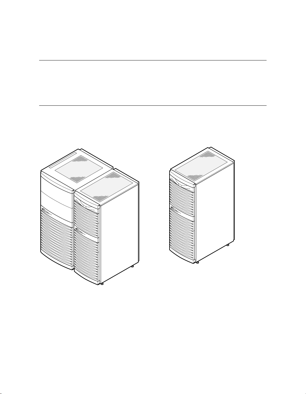
1.1 AlphaServer GS160/320 and GS80 Systems
The AlphaServer GS160/320 system and GS80 rack system are separate,
but related, in that they use the same switch technology. The CPU
modules, memory modules, and power modules are also the same. In
the GS160/320 system, the modules are in a system box in a cabinet. In
theGS80racksystem,themodulesareinadrawer.
Figure 1–1 AlphaServer GS160 and GS80 Systems
GS80 System
GS160 System
1-2 AlphaServer GS80/160/320 User's Guide
PK-0654-00
Page 15

AlphaServer GS160/320 System
The AlphaServer GS160 system cabinet contains up to two system boxes
supporting a maximum of 16 CPU modules.
In an AlphaServer GS320 system, a second system cabinet is used to expand the
system (up to four system boxes containing a maximum of 32 CPU modules).
A power cabinet contains the power components, I/O boxes, and storage.
Additional I/O and storage can be housed in expander cabinets.
AlphaServer GS80 System
The AlphaServer GS80 rack system contains up to two system drawers, I/O, and
storage. Each system drawer supports up to four CPU modules, for a maximum
of eight CPUs per system. Power components are mounted at the bottom of the
rack cabinet.
An expander cabinet can be used to house additional I/O and storage.
System Management Console
The console device, called the system management console (SMC), is a Compaq
Deskpro PC, a DECserver 90M terminal server, and associated hardware and
software. For installation instructions and user information, see the
AlphaServer GS80/160/320 System Management Console Installation and
User’s Guide.
Introduction 1-3
Page 16

1.2 Firmware and Utilities Overview
Firmware residing in ROM on CPU and other modules in the system
provides commands for booting the operating system, testing devices
and I/O adapters, and other tasks useful in operating and maintaining
a running system. You type commands at the console device.
SRM Console
Systems running the Tru64 UNIX or OpenVMS operating systems are
configured from the SRM console, a command-line interface (CLI). From the
CLI you can enter commands to configure the system, view the system
configuration, and boot the system.
System Control Manager (SCM)
The SCM firmware allows the user to access the system remotely. In addition,
the SCM:
• Monitors and notifies the user of power or temperature alert conditions
• Controls initial system power-up
• Manages hard partitions
LFU (Loadable Firmware Update Utility)
You can boot this utility (with the SRM boot command) whenever you need to
update the SRM console firmware or I/O device firmware. The CD with the
AlphaServer firmware is updated periodically.
1-4 AlphaServer GS80/160/320 User's Guide
Page 17
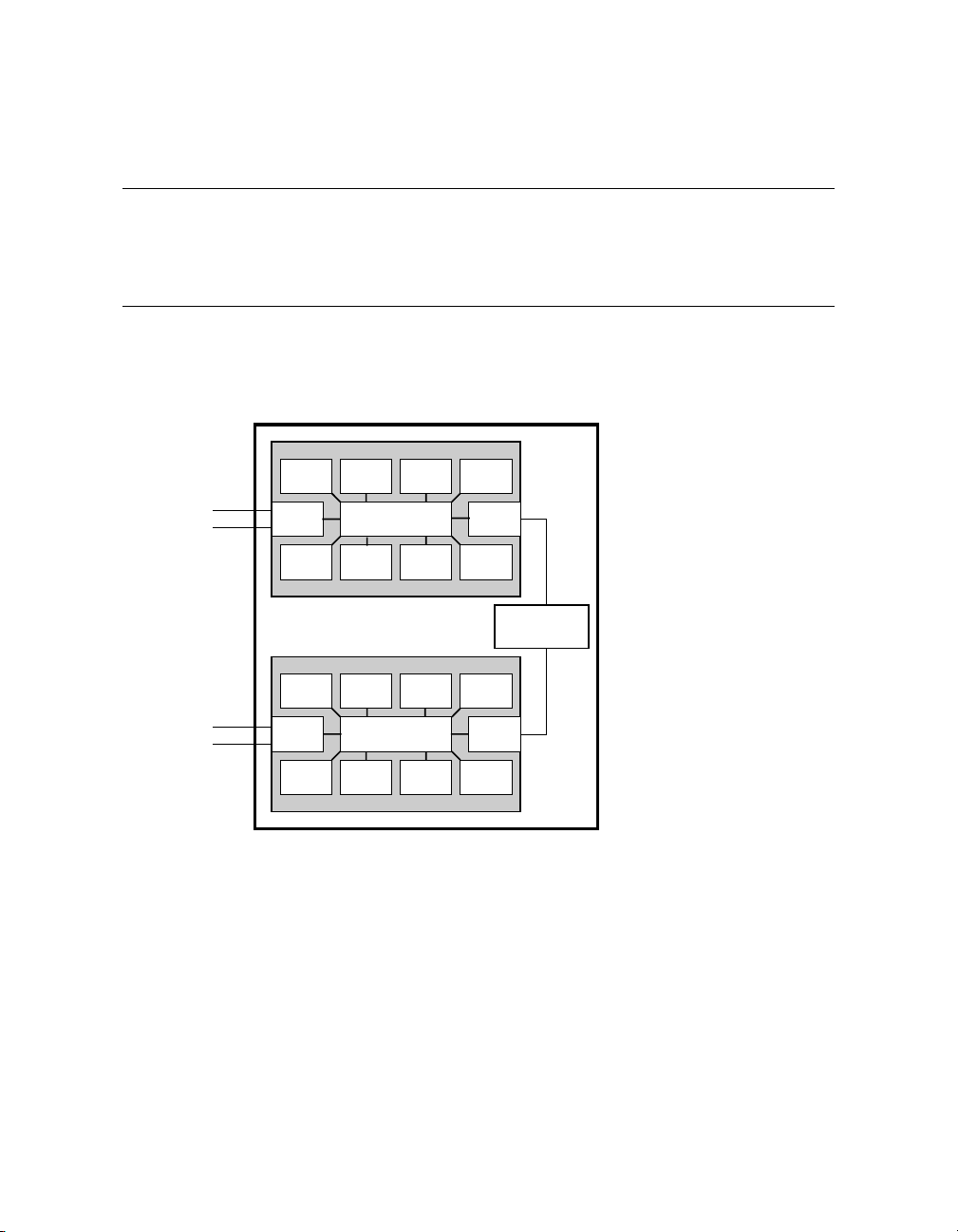
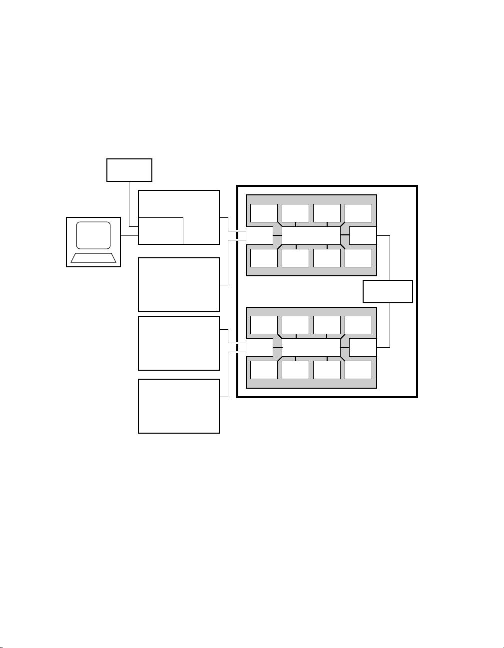
1.3 System Architecture
Each QBB in a GS160/320 system and each QBB (system drawer) in a
GS80 system has a backplane and a switch supporting the CPU
modules, memory modules, and I/O riser modules. Figure 1–2 shows
twoQBBsinasingle-boxsystem.
Figure 1–2 Sample System Architecture
System Box
To PCI Boxes
To PCI Boxes
CPU
I/O GP
MEM
CPU
I/O GP
MEM
CPU CPU CPU
Switch
MEMMEMMEM
Distribution
Board
CPU CPU CPU
Switch
MEMMEMMEM
PK-0601A-98
The backplane of each QBB (GS160/320 systems) and drawer (GS80 rack
systems) contains the switch that interconnects the CPU modules, memory
modules, and I/O riser modules.
The global port and distribution board provide the interconnect for the QBBs.
In a two-box system, a hierarchical switch is used as the interconnect, in place
of the distribution board.
I/O riser modules connect the PCI boxes to the QBB backplane.
Introduction 1-5
Page 18

Page 19

Chapter 2
GS160/320 System Overview
Each system cabinet contains one or two system boxes. The system box houses
two quad building blocks, or QBBs. CPU modules, memory modules, power
modules, and I/O riser modules plug into the QBB backplane.
The power cabinet contains power components, PCI boxes, and storage shelves.
This chapter provides an overview of the system in these sections:
• System Characteristics
• System Box Architecture
• Quad Building Block (QBB) Components
• Power System
• PCI I/O
• Control Panel
GS160/320 System Overview 2-1
Page 20
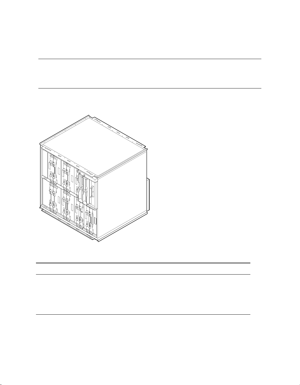
2.1 System Characteristics
The illustration shows the BA51A-AA system box. Table 2–1 lists the
system box characteristics. Table 2–2 lists power cabinet and
environmental characteristics.
Figure 2–1 System Box
PK0611
Table 2–1 System Box Characteristics
Characteristic Specification
Size
Weight 54.55 kg (120 lb) maximum
Maximum heat dissipation 2000 w (6,850 Btu/hr)
2-2 AlphaServer GS80/160/320 User's Guide
535 mm H x 550 mm W x 475 mm D
(21.06 in. x 21.65 in. x 18.7 in.)
Page 21

Table 2–2 Power Cabinet and System Environmental Characteristics
Power Cabinet Specifications
Electrical
Voltage
120/208 VAC (U.S)
380–415 VAC (Europe)
200 VAC (Japan)
Phase 3-phase
Frequency 50–60 Hz
Maximum input
21 A
current/phase
Heat dissipation
1
9,300 W/31,800 Btu/Hr
Environmental
Temperature
Operating: 5° to 35°C (41 to 95°F)
Not operating: -40° to 66°C (-40° to 151°F)
Humidity
Operating: 10% to 90%
Not operating: 10% to 95%
Altitude
Operating: 0 to 3 km (0 to 10,000 ft)
Not operating: 0 to 12.2 km (0 to 40,000 ft)
1
A fully configured system with three system boxes, nine power supplies, two
PCI boxes, and storage shelf.
GS160/320 System Overview 2-3
Page 22
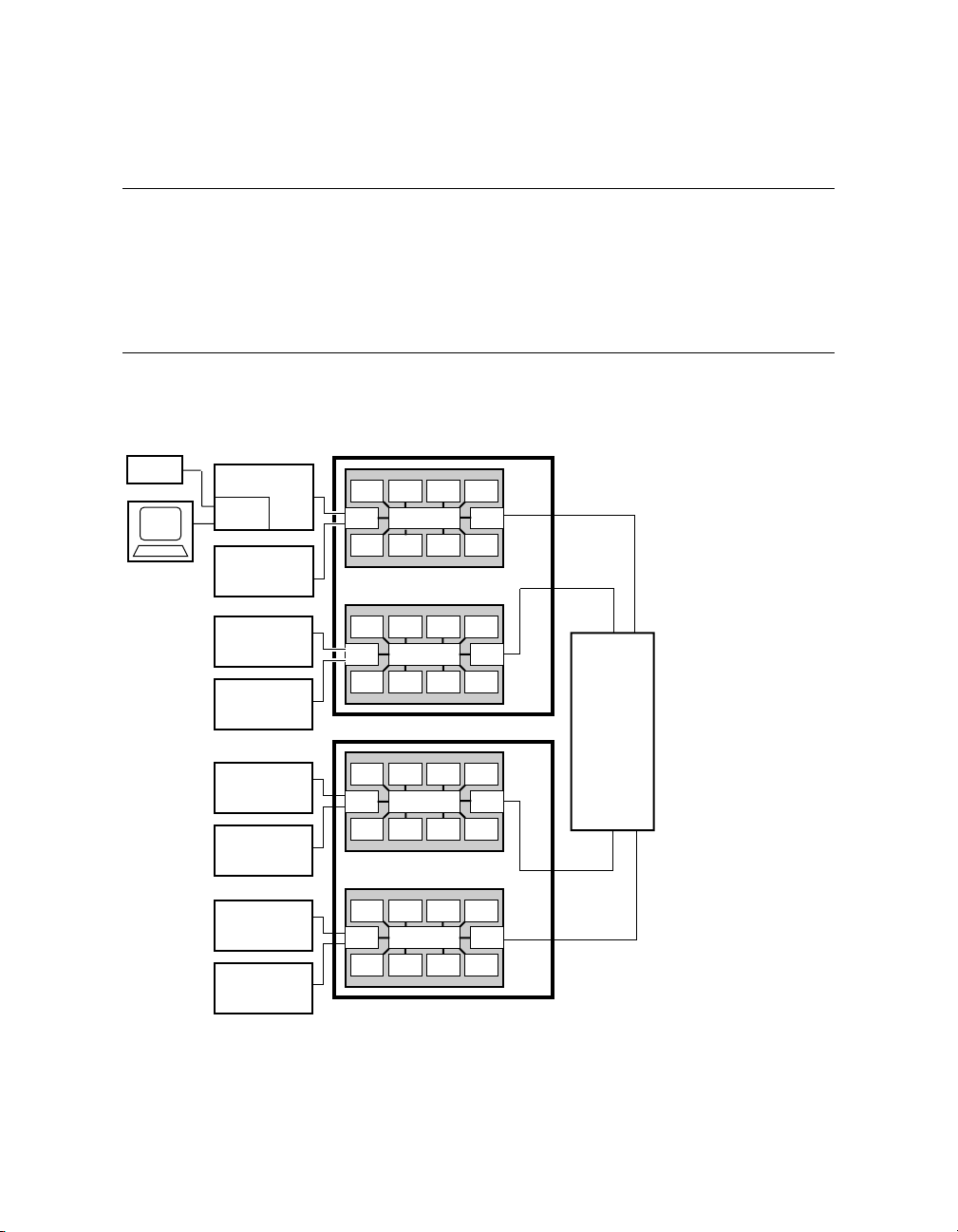
2.2 System Box Architecture
The system box houses two quad building blocks (QBBs). Each QBB
has a backplane with a switch interconnect that supports up to four
CPU modules, four memory modules, two power modules, two I/O riser
modules, and a global port. Figure 2–2 shows two system boxes
connected by the hierarchical switch. Figure 2–3 shows one system box
and the distribution board.
Figure 2–2 System Box Block Diagram (16-Processor System)
System Box 1
Modem
Operator
Console
PCI Box
Standard
I/O SCM
PCI Box
PCI Box
PCI Box
CPU
CPU CPU CPU
I/O GP
Switch
MEM
CPU
CPU CPU CPU
I/O GP
Switch
MEM
MEMMEMMEM
MEMMEMMEM
System Box 2
Hierarchical
Switch
CPU
PCI Box
PCI Box
PCI Box
PCI Box
CPU CPU CPU
I/O GP
Switch
MEM
CPU
CPU CPU CPU
I/O GP
Switch
MEM
MEMMEMMEM
MEMMEMMEM
2-4 AlphaServer GS80/160/320 User's Guide
PK-0623-98
Page 23
The switch on the backplane connects the CPU modules, memory modules, I/O
riser modules, and global port. In an 8-P system, the global ports connect the
QBBs to the distribution board. In a 16-P or a 32-P system, the global ports
connect the QBBs to the hierarchical switch.
Figure 2–3 System Box Block Diagram (8-Processor System)
Operator
Console
Modem
PCI Box
Standard
I/O SCM
PCI Box
PCI Box
PCI Box
System Box
CPU
I/O GP
MEM
CPU
I/O GP
MEM
CPU CPU CPU
Switch
MEMMEMMEM
CPU CPU CPU
Switch
MEMMEMMEM
Distribution
Board
PK-0601-98
GS160/320 System Overview 2-5
Page 24
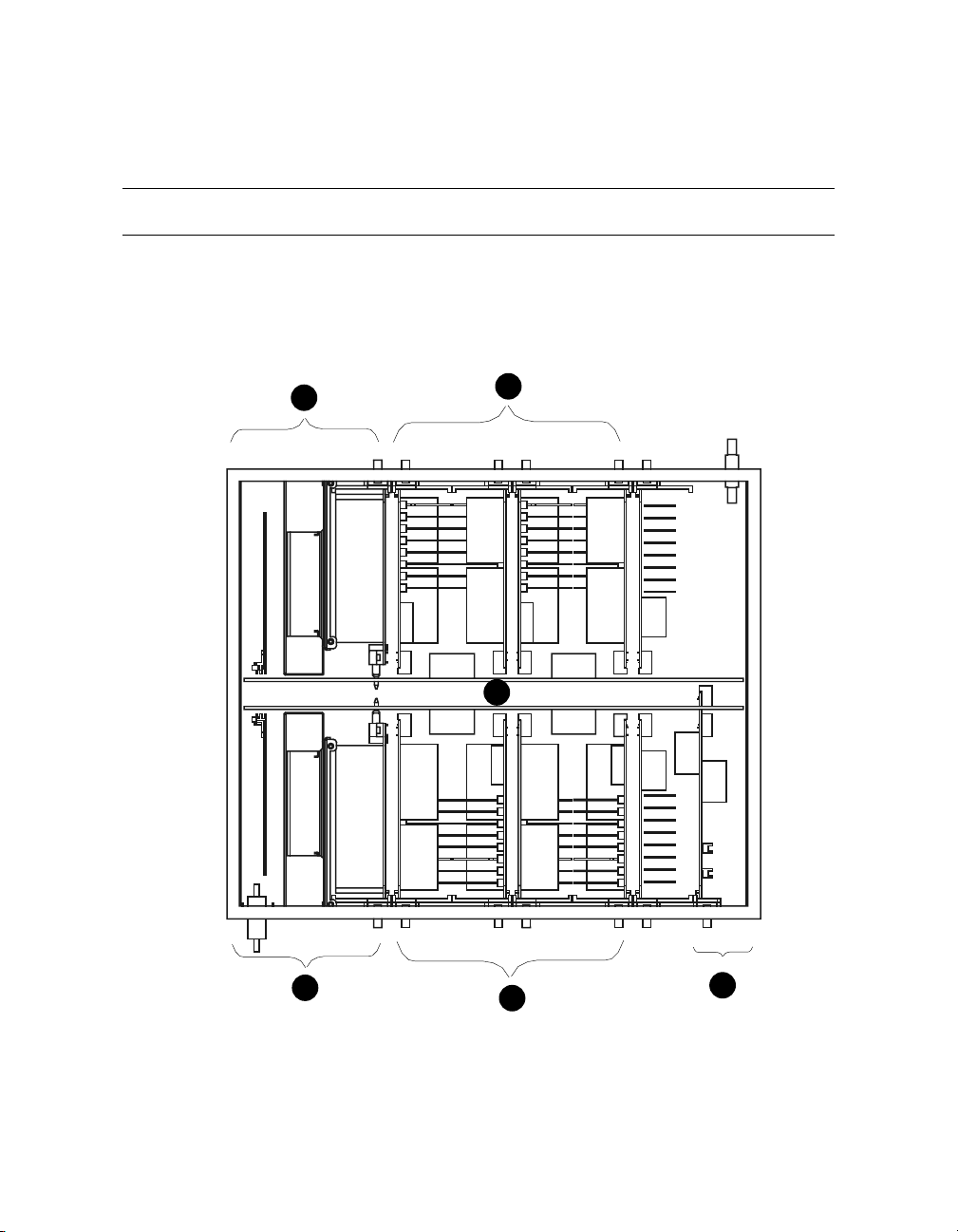
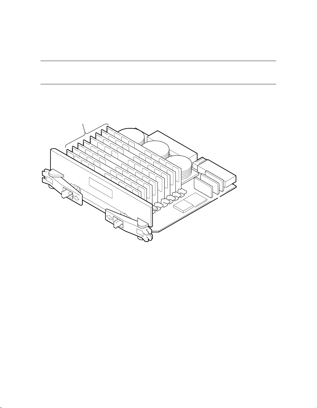
2.3 Quad Building Block (QBB) Components
Figure2–4showstwoQBBsbacktobackinthesystembox.
Figure 2–4 System Box QBBs (Top View)
QBB 1 (Front)
Top View
1
2
4
1
QBB 0 (Rear)
2-6 AlphaServer GS80/160/320 User's Guide
2
3
PK-0612-98
Page 25

The QBB backplanes are attached to a stiffener and mounted in a system box
enclosure. Each backplane has a differently positioned cutout to accommodate
the global port modules. A global port module is mounted on the front of one
QBB and the other is mounted on the back of the other QBB, putting both
global port modules near the distribution board (or the hierarchical switch)
when the system box is installed in the cabinet.
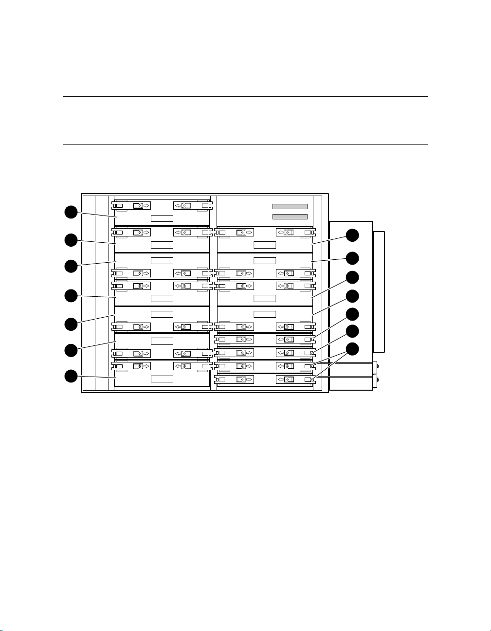
The callouts in Figure 2–4 point to the location of these components in the
system box:
I/O riser module area. Each QBB supports up to two I/O riser
➊
modules.
CPU module and memory module area. Each QBB holds four CPUs
➋
and four memory modules.
Global port area.
➌
Backplane area.
➍
GS160/320 System Overview 2-7
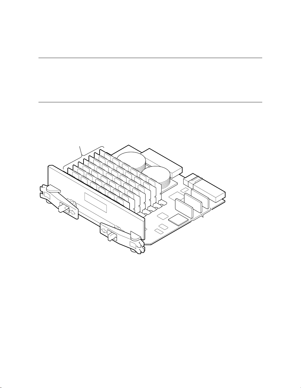
Page 26
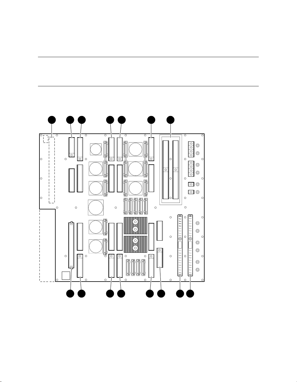
2.3.1 Backplane
Each QBB backplane is located at the center of the system box. Figure
2–5 shows an unpopulated backplane (no modules installed) as you
would see it from the front of the system box.
Figure 2–5 Backplane (System Box, Front View)
1 2 3 4 3 4 5
6 4 3 4 3 7 8 9
2-8 AlphaServer GS80/160/320 User's Guide
PK0600
Page 27

The CPU, memory, power, and I/O riser modules plug into the backplane.
Because of the orientation of the QBB backplanes, the modules are situated
differently in the front and rear of the system box. See Section 3.5 for more
information.
The switch interconnect on the backplane allows any processor to access any
memory on the QBB. The backplane also provides power to the modules.
Global port module
➊
Directory module
➋
CPU module
➌
Memory module
➍
I/O riser modules
➎
Clock splitter module
➏
Power system manager (PSM) module
➐
Main power module
➑
Auxiliary power module
➒
GS160/320 System Overview 2-9
Page 28
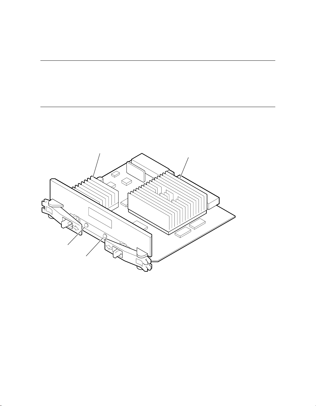
2.3.2 CPU Module
A CPU module comes with an Alpha microprocessor chip with a Bcache, cache control and TAG comparison logic, clock logic, and a DCDC power converter. Also included on the module is logic for
implementing self-test diagnostics. Each module has a Run LED and a
Hot Swap LED.
Figure 2–6 CPU Module
Run LED
Hot Swap
LED
Power
Converter
CPU
Chip
PK0602
2-10 AlphaServer GS80/160/320 User's Guide
Page 29
2.3.3 Memory Module
A memory module has eight DIMM slots. See Section 3.7 for memory
configuration guidelines.
Figure 2–7 Memory Module
DIMMs
PK0603
GS160/320 System Overview 2-11
Page 30
2.3.4 Directory Module
In a GS160/320 system, one directory module is required for each QBB
in a system box. In a two-drawer GS80 system, a directory module is
required in each system drawer. No directory module is needed in a
one-drawer system. The directory module functions as a memory
coherency manager.
Figure 2–8 Directory Module
Directory
DIMMs
2-12 AlphaServer GS80/160/320 User's Guide
PK0606
Page 31

2.3.5 Power Modules
Two power modules are installed in the QBB backplane. The main
power module and the auxiliary power module convert 48 VDC to the
various voltages required to power the QBB.
Figure 2–9 Power Modules
Auxiliary Power Module
Main Power Module
PK-0604-99
GS160/320 System Overview 2-13
Page 32

2.3.6 Power System Manager Module
Each QBB has one power system manager (PSM) module. This module
monitors CPUs, voltages, temperatures, and blower speed in the
cabinet and reports this information to the system control manager
(SCM).
Figure 2–10 Power System Manager Module
PK0607
The PSM module is connected to other PSM modules and the SCM microprocessor (located on the standard I/O module) through the console serial bus
(CSB). The SCM is the master; the PSM can only operate as a slave. The PSM
controls the powering on/off and resetting of all modules within the QBB and of
the QBB itself. The PSM also contains three I
bus channel to each CPU in the QBB. The PSM module retrieves information
from the I
2
C EEROMs residing on the CPUs, memory modules, and the QBB
2
C bus interfaces and a serial I/O
backplane. The PSM uses a serial I/O port connection to communicate with one
CPU module at a time. The PSM can only perform a function as the result of a
request from the SCM.
2-14 AlphaServer GS80/160/320 User's Guide
Page 33

2.3.7 Clock Splitter Module
The clock splitter module converts one global signal to identical copies
of a signal that is then distributed to master phase lock loops
associated with the ASICs and the system processors within a QBB. It
also generates independent clock signals for the I/O domain.
Figure 2–11 Clock Splitter Module
PK2222
GS160/320 System Overview 2-15
Page 34

2.3.8 I/O Riser Module
TheI/OrisermoduleisusedtoconnecttheQBBbackplanetoaPCI
box. A “local” I/O riser module is located on the QBB backplane; a
“remote” I/O riser module is in the PCI box.
Figure 2–12 I/O Riser Module
2-16 AlphaServer GS80/160/320 User's Guide
PK0605
Page 35

2.3.9 Global Port Module
The global port provides the interconnect to the other QBB(s) through
the distribution board or the hierarchical switch.
Figure 2–13 Global Port Module
Front QBB
Rear QBB
PK-0655-00
GS160/320 System Overview 2-17
Page 36

2.3.10 Distribution Board
In single-box systems, a distribution board connects the two QBBs
through the global ports.
Figure 2–14 Distribution Board
A1
B1
B0
A0
2-18 AlphaServer GS80/160/320 User's Guide
PK1244
Page 37
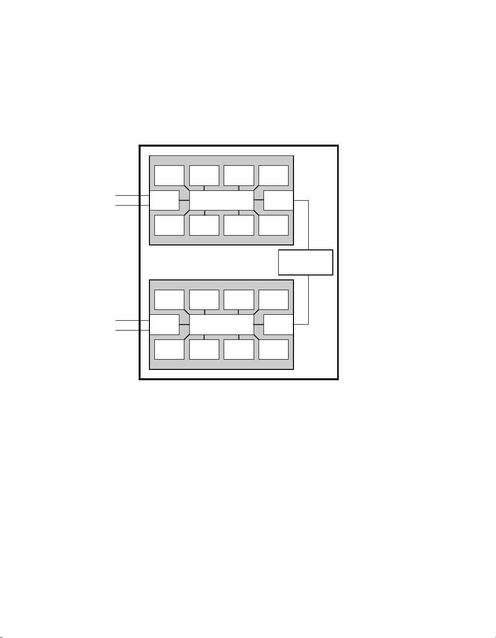
Figure 2–15 is a block diagram showing the distribution board as the
interconnect between two QBBs.
Figure 2–15 Distribution Board in Single-Box System
System Box
To PCI Boxes
To PCI Boxes
CPU
I/O GP
MEM
CPU
I/O GP
MEM
CPU CPU CPU
Switch
MEMMEMMEM
CPU CPU CPU
Switch
MEMMEMMEM
Distribution
Board
PK-0601A-98
GS160/320 System Overview 2-19
Page 38

2.3.11 Hierarchical Switch
In two-box systems, a hierarchical switch links the QBBs through the
global ports. The hierarchical switch connects QBBs in three- and
four-box systems also.
Figure 2–16 Hierarchical Switch
System
Box 2
System
Box 4
System
Box 3
2-20 AlphaServer GS80/160/320 User's Guide
System
Box 1
PK0626
Page 39

The hierarchical switch links the QBBs in systems having more than one
system box. Figure 2–16 shows cable connectors for each system box (a pair of
connectors for two signal cables routed to each QBB global port in the system).
The hierarchical switch power manager (HPM) module controls power and
monitors the temperature inside the hierarchical switch housing. The HPM
module, along with the PSM modules and PBM modules, report status
information to the SCM.
GS160/320 System Overview 2-21
Page 40

2.4 Power System
Each system box has a power subrack with up to three 48 VDC power
supplies. Figure 2–17 shows the power system for a 32-P system. See
Section 3.3 for power configuration rules.
Figure 2–17 Power System
System
Box 4
(Brown)
System
Box 3
(Orange)
Orange
Brown
Blue
Green
System
Box 2
(Green)
System
Box 1
(Blue)
Subrack 1
(Blue)
Subrack 2
(Green)
Subrack 3
(Orange)
Subrack 4
(Brown)
AC Input
2
AC Input
1
2-22 AlphaServer GS80/160/320 User's Guide
PK0615A
Page 41

Power cables and components are color-coded to ensure proper identification
and easy handling.
NOTE: Color-coded components and power cables must match to ensure proper
power distribution, particularly in hard-partitioned systems.
Figure 2–17 shows each system box and its color-related power subrack and AC
input box. The AC input box also has color-coded circuit breakers. Each AC
input box provides power to the subracks, PCI boxes, and storage shelves.
Power distribution and signal cables are connected from the power subrack to
the QBB backplanes through a power distribution bulkhead. Another cable is
used to provide power to the blower, located at the bottom of the system cabinet,
and the control panel, located in the power cabinet.
Each QBB has its own main power module and auxiliary power module. Each
CPU module has its own power converter that converts the 48 VDC to the
required voltage.
When the main power circuit breaker (CB1) is on and the AC input box is
plugged in, the console serial bus (CSB) has auxiliary power (Vaux), enabling
the system control manager (SCM) to power up the system.
See Section 2.4.1 for more information on the AC input box and circuit breakers.
GS160/320 System Overview 2-23
Page 42

2.4.1 AC Input Box
A system has two AC input boxes. Figure 2–18 shows the circuit
breakers (CB1–CB11), LEDs (L1–L3), and connectors (J1–J22) on the AC
input box.
Figure 2–18 AC Input Box
J-1 J-2 J-3
J-4 J-5 J-6
L1 L2 L3
CB1
J-7
J-12
J-9
J-14
CB5 CB7 CB9 CB11CB3
J-15
J-19
J-20J-11 J-13
J-16
J-21
J-18
J-17J-8 J-10
Cabinet
Front
J-22
CB10CB8CB6CB4CB2
Cabinet
Rear
PK-0645-99
2-24 AlphaServer GS80/160/320 User's Guide
Page 43

The three LEDs on the AC input box should be lit at all times, indicating that
all three power phases are present in the 3-phase AC input.
Table 2–3 lists the AC input box circuit breakers and the lines they protect.
Table 2–3 AC Input Box Circuit Breakers
Circuit Breaker Line(s) Protected
CB1 (Main) All lines protected.
CB2 J1
CB3 J2
CB4 J3
CB5 J4
CB6 J5
CB7 J6
CB8 J7, J8, J9, J10
CB9 J11, J12, J13, J14
CB10 J15, J16, J17, J18
CB11 J19, J20, J21, J22
GS160/320 System Overview 2-25
Page 44

2.5 PCI I/O
The power cabinet contains at least one PCI master box, and may
contain PCI expansion boxes.
Figure 2–19 PCI Master Box
Front
DVD/CD-ROM
Power Supply LEDs Power Supply LEDs
Rear
Remote I/O
Riser Module
Keyboard
Mouse
Remote I/O
Riser Module
COM 2
Serial Port
Local Terminal
Port
Operator
Control
Panel
Parallel
Port
LEDs
CSB Node
ID Switch
CSB
USB
Ports
2-26 AlphaServer GS80/160/320 User's Guide
Modem
Port
PK0656
Page 45

A PCI master box has a standard I/O module and a DVD/CD-ROM drive as
shown in Figure 2–19. PCI expansion boxes provide additional slots for options.
Each PCI power supply has three LEDs: Vaux OK, Power OK, and Swap OK.
BA54A-AA PCI Box
The BA54A-AA PCI box is a PCI master box. It contains the following
components:
• Backplane with a standard I/O module
• Thirteen I/O option slots
• DVD/CD-ROM drive
• SCSI disk drive
• Ports: one local terminal port, one serial port, one modem port, one parallel
port, two USB ports, one keyboard port, one mouse port, one CSB port, and
one control panel port
• Two I/O riser slots
• Two power supplies
BA54A-BA PCI Box
The BA54A-BA box is a PCI expansion box and contains the following
components:
• Backplane with fourteen option slots
• Two I/O riser slots
• Two power supplies
GS160/320 System Overview 2-27
Page 46
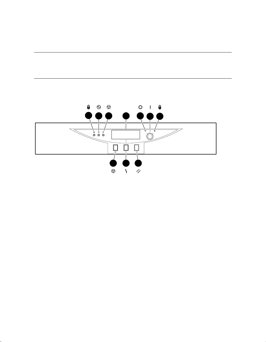
2.6 Control Panel
The control panel is located at the top of the power cabinet. It has a
three-position Off/On/Secure switch, three pushbuttons, three status
LEDs, and a diagnostic display.
Figure 2–20 Control Panel
213 4
657
9 108
PK0621
2-28 AlphaServer GS80/160/320 User's Guide
Page 47

The callouts in Figure 2–20 point to these components on the control panel:
Secure LED – When lit, indicates that the keyswitch is in the Secure
➊
position and system is powered on. All pushbuttons and SCM functions
are disabled, including remote access to the system.
Power OK LED – When lit, indicates at least one QBB is powered on and
➋
remote console operations are enabled. The keyswitch is in the On
position.
Halt LED – When lit with the Power LED, indicates the system is powered
➌
on, remote console operations are enabled, and the Halt pushbutton is
pressed.
When lit with both Power LED and Secure LED, indicates a powered on
system, disabled remote console operations, and Halt pushbutton is
pressed in.
Diagnostic display indicates system status.
➍
Off switch position – System is powered off and cannot be powered on
➎
remotely.
On switch position – System is enabled to be powered up. A remote system
➏
user can power on or power off the system.
Secure switch position – System is powered on and cannot be remotely
➐
powered on or off. All pushbuttons and SCM functions are disabled.
Halt pushbutton – Pressing this pushbutton causes the operating system
➑
to perform a halt, with no captured error information. The system will
automatically reset if the auto_fault_reset environment variable is
enabled.
Fault pushbutton – Pressing this pushbutton causes a system reset
➒
without clearing captured error information in the control and status
registers.
Reset pushbutton – Pressing this pushbutton causes a system reset that
➓
clears captured error information.
GS160/320 System Overview 2-29
Page 48

2.6.1 Control Panel LEDs
Figure 2–21 shows the various control panel LED status indications.
Figure 2–21 Control Panel LED Status
Control Panel LEDs Status
Secure Power
OK
On
Off
Halt
System powered on; remote console disabled; pause mode.
System powered on; remote console disabled.
System powered on; remote console enabled; remote console
halt or Halt button depressed.
System powered on; remote console enabled.
System powered off for any of the following reasons:
o No AC power available
o Keyswitch in Off position
o Keyswitch in On position but system powered off by remote
console or power/temperature failure
PK-0622-99
2-30 AlphaServer GS80/160/320 User's Guide
Page 49

Chapter 3
GS160/320 System Configuration Rules
This chapter provides configuration rules for the following:
• GS160 System Cabinet
• GS320 System Cabinets
• Power Cabinet
• System Box
• QBB Color Code
• Memory Configurations
• Memory Interleaving Guidelines
• PCI Boxes
• PCI Box Slot Configuration
• Expander Cabinet
GS160/320 System Configuration Rules 3-1
Page 50

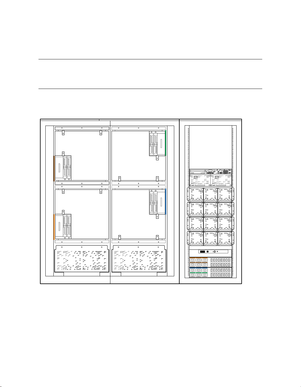
3.1 GS160 System Cabinet
Figure 3–1 shows the front view of the system cabinet and the power
cabinet. One system cabinet houses either one system box or two
system boxes. In a one-box system, a distribution board connects the
two QBBs. In a two-box system, a hierarchical switch connects the
QBBs.
Figure 3–1 GS160 System
System
Box 2
System
Box 1
3-2 AlphaServer GS80/160/320 User's Guide
PK0614
Page 51

About the System Cabinet
The cabinet contains the following components:
• Vertical mounting rails
• Wrist strap for static discharge protection
GS160 Configuration Rules
• System box 1 (see Figure 3–1) is mounted in the lower half of the cabinet,
above the blower.
• System box 2 is mounted in the upper half of the cabinet, over system box 1.
GS160/320 System Configuration Rules 3-3
Page 52
3.2 GS320 System Cabinets
Figure 3–2 shows the front view of the system cabinets. Two system
cabinets house either three system boxes or four system boxes. A
hierarchical switch is used to connect the QBBs.
Figure 3–2 GS320 System
System
Box 4
System
Box 3
System
Box 2
System
Box 1
PK0615
3-4 AlphaServer GS80/160/320 User's Guide
Page 53

GS320 System Configuration Rules
• In system cabinet 1, system box 1 (see Figure 3–2) is mounted in the lower
half of the cabinet, above the blower. System box 2 is mounted in the upper
half of the cabinet, above system box 1.
• In system cabinet 2, system box 3 is mounted in the lower half of the
cabinet; system box 4, the upper half of the cabinet.
GS160/320 System Configuration Rules 3-5
Page 54

3.3 Power Cabinet
One power cabinet is required for all systems. The power cabinet
houses the control panel, AC input boxes, power supplies, PCI I/O
boxes, and storage.
Figure 3–3 Power Cabinet Configuration (32-P System)
System
Box 4
(Brown)
System
Box 3
(Orange)
Orange
Brown
Blue
Green
System
Box 2
(Green)
System
Box 1
(Blue)
Subrack 1
(Blue)
Subrack 2
(Green)
Subrack 3
(Orange)
Subrack 4
(Brown)
AC Input
2
AC Input
1
3-6 AlphaServer GS80/160/320 User's Guide
PK0615A
Page 55

Power System Requirements
• Each system box requires a power subrack.
• Each power subrack has three power supplies. The third power supply is
always redundant. See Section 3.3.1 for power supply slot assignments.
• Two AC input boxes are required.
Cables, AC input boxes (including AC circuit breakers), power subracks, and
system boxes are color-coded at cable connections to ensure proper cabling.
Figure 3–3 shows the color coding scheme for a 32-P system.
PCI boxes and storage shelves are installed in the upper half of the power
cabinet.
GS160/320 System Configuration Rules 3-7
Page 56

3.3.1 Power Supply Slot Assignments
Figure 3–4 show the power supply slot assignments in each power
subrack.
Figure 3–4 Power Supply Slot Assignments
Power
Subrack
1
1 2 3
R
R
Power
Subrack
2
1 2 3
R
Power
Subrack
3
1 2 3
R
Power
Subrack
R
4
indicates redundant power supply slot.
1 2 3
Blue
Green
Orange
Brown
Power
Cabinet
Bulkhead
Power
Cabinet
Bulkhead
AC Input 2
AC Input 1
PK-0624-99
3-8 AlphaServer GS80/160/320 User's Guide
Page 57

Power Supply Configuration Rules
• Power subracks are always mounted in the same power cabinet location,
regardless of the number of system boxes.
• Power supply slot assignments remain the same in all systems, regardless
of the number of system boxes.
• A redundant power supply slot is always the last slot to be used in a
subrack.
GS160/320 System Configuration Rules 3-9
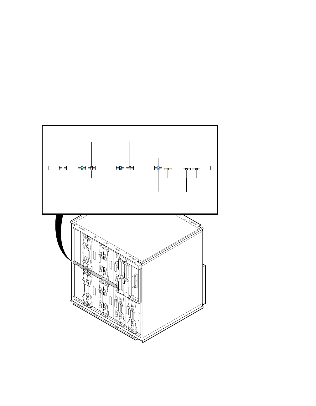
Page 58

3.4 System Box
The system box contains two QBBs. Figure 3–5 shows a fully populated
QBB as seen from the front of the cabinet. Figure 3–6 shows the second
QBB at the rear of the cabinet.
Figure 3–5 System Box QBB (Cabinet Front)
Memory 2 Memory 0
Directory CPU 3 CPU 1
I/O Riser
I/O Riser
Signal Cable
Clock
Splitter
Memory 3 Memory 1
CPU 2 CPU 0
PSM
3-10 AlphaServer GS80/160/320 User's Guide
Main
Power
Auxiliary
Power
PK0610
Page 59

System Box Configuration Rules
• A system box has two QBBs.
• A QBB supports up to four CPU modules.
• A QBB supports up to four memory modules.
• A QBB has up to two I/O riser modules; each I/O riser module connects to
one PCI box.
• A system box supports up to four PCI boxes.
Figure 3–6 System Box QBB (Cabinet Rear)
Memory 3
Clock
Splitter
Global Port - Odd
(Connected to front QBB)
Auxiliary
Power
Main
Powe r
PSM
CPU 0
CPU 2
Memory 1
Powe r
Connectors
I/O Riser
I/O Riser
CPU 1 CPU 3
Memory 0
Memory 2
Directory
Global Port - Even
(Connected to back QBB)
PK2228
GS160/320 System Configuration Rules 3-11
Page 60
3.5 QBB Color Code
Figure 3–7 and Figure 3–8 show the center bar color code for module
placement in the QBB. Note that CPU and memory slots are colorcoded to ensure the correct placement of each module.
Figure 3–7 QBB Center Bar Color Code (Cabinet Front)
Directory
(White)
Memory 3
Clock
Splitter
(Green)
CPU 3
(Blue)
(Gray)
Memory 2
(Gray)
Memory 1
CPU 2
(Blue)
CPU 1
(Blue)
(Gray)
Memory 0
(Gray)
(Orange)
CPU 0
(Blue)
PSM
Auxiliary
Main
Powe r
(Yellow)
Powe r
(Red)
3-12 AlphaServer GS80/160/320 User's Guide
PK0628
Page 61
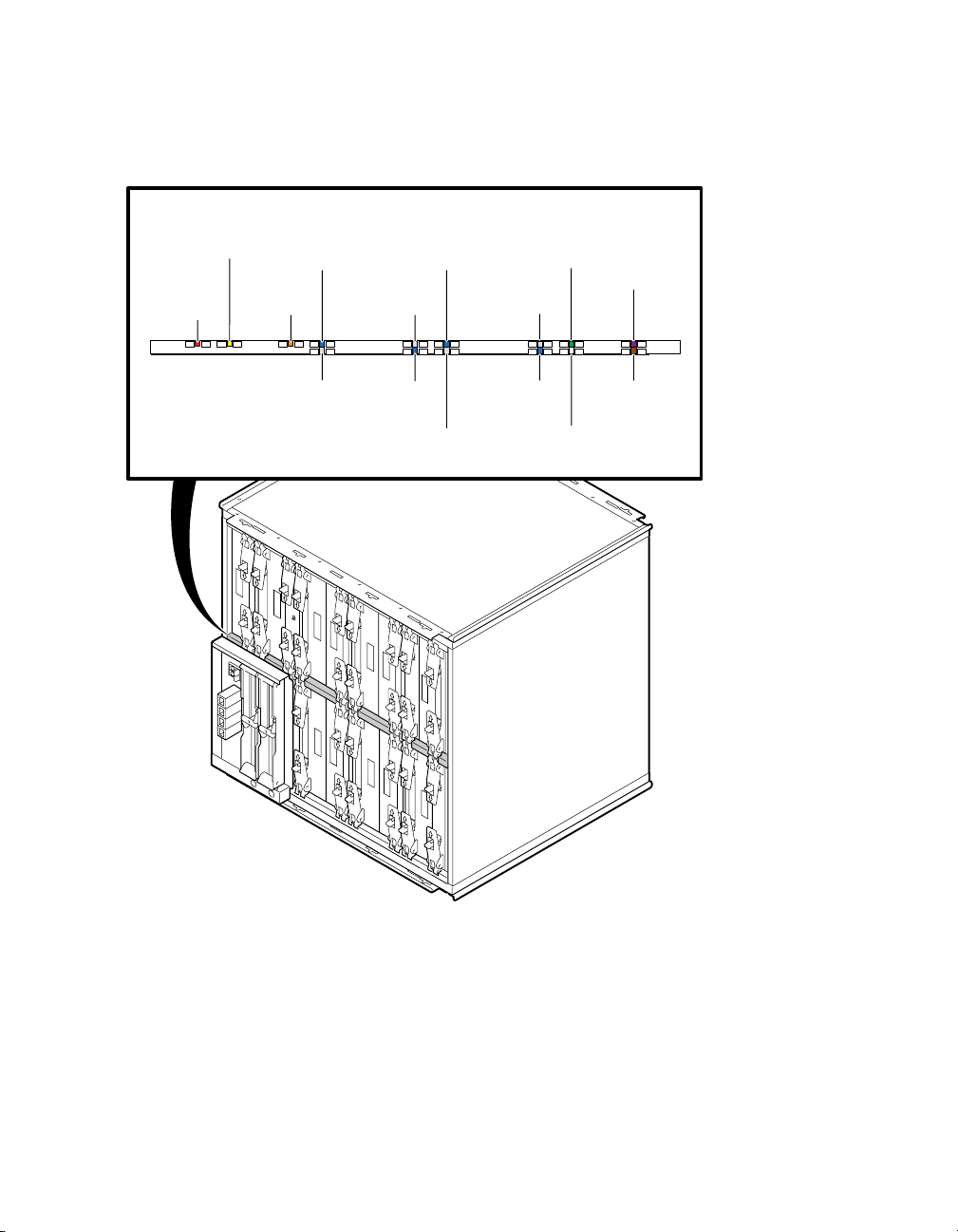
Figure 3–8 QBB Center Bar Color Code (Cabinet Rear)
(Yellow)
Auxiliary
Powe r
(Red)
Main
Powe r
CPU 0
(Blue)
PSM
(Orange)
Memory 0
(Gray)
CPU 2
(Blue)
Memory 1
(Gray)
CPU 1
(Blue)
Memory 3
(Gray)
Clock
Splitter
(Green)
Memory 2
(Gray)
CPU 3
(Blue)
Directory
(White)
Global
Por t 1
Global
Por t 0
PK2229
GS160/320 System Configuration Rules 3-13
Page 62

3.6 Memory Configurations
A memory module has eight DIMM slots. Two arrays (Array 0 and
Array 1), consisting of four DIMMs, can be installed on each module. A
directory DIMM is required for each array in systems having more
than four processors. Directory DIMMs are installed on the directory
module.
Figure 3–9 Memory Module and Directory Module
Array 0
Array 1
DIMM 0
DIMM 1
DIMM 2
DIMM 3
DIMM 0
DIMM 1
DIMM 2
DIMM 3
Memory Module
Directory Module
DIMM 0
DIMM 1
DIMM 2
DIMM 3
DIMM 4
DIMM 5
DIMM 6
DIMM 7
PK-0651-99
3-14 AlphaServer GS80/160/320 User's Guide
Page 63

Memory Configuration Guidelines
• On a memory module, DIMMs are divided into two groups of four called
arrays.
• A memory module must be populated on an array-by-array basis; that is,
groups of four DIMMs must be installed.
• DIMMs in an array must be the same size and type.
• DIMM sizes include 256 Mbyte, 512 Mbyte, and 1 Gbyte.
There are two types of DIMMs: single density (SD) and double density (DD).
• Density does not affect interleaving.
• One directory module DIMM is required for each memory array in systems
with more than one QBB.
• The type and number of DIMMs installed in the directory module is based
on the number of memory arrays populated and the physical size of the
memory arrays. See the table below.
• A larger DIMM type may always be used in place of the minimum required
DIMM type.
Directory DIMM Type Memory Array Size Part Number
0 256 MB 54-25019-AA
1 1 GB 54-25023-AA
2 2 GB 54-25023-BA
3 2 GB 54-25023-CA
4 4 GB 54-25023-DA
GS160/320 System Configuration Rules 3-15
Page 64

3.7 Memory Interleaving Guidelines
Table 3–1 Interleaving Memory Modules
Memory Interleaving Guidelines
4-way
8-way One memory module with two arrays populated.
16-way
32-way
The default interleave. One memory module with
one array populated (or most mixes not discussed
below).
Preferred method: Two memory modules with one
array populated on each module.
Two memory modules, each with two arrays
populated.
Preferred method. Four memory modules with one
array populated on each module.
Four memory modules with two arrays populated on
each module.
3-16 AlphaServer GS80/160/320 User's Guide
Page 65

Memory Interleaving Guidelines
• The larger the interleaving factor, the better the system performance.
• Avoid mixing memory sizes; this limits interleaving capability and
potential bandwidth.
GS160/320 System Configuration Rules 3-17
Page 66

3.8 PCI Boxes
A QBB supports up to two PCI boxes. A cable connects the QBB “local”
I/O riser to the “remote” I/O riser in the PCI box. There are two I/O
ports on a local I/O riser. Each I/O port is used to connect to one
remote I/O riser. Figure 3–10 shows QBB0 connected to PCI box 0 and
PCI box 1.
Figure 3–10 Sample I/O Subsystem
PCI Box 0 PCI Box 1
PCI Bus
PCA
Chip
PCI Bus
PCA
PCI Bus PCI Bus
Remote I/O
Riser 1
10 32
Local I/O Riser Local I/O Riser
Chip
Remote I/O
Riser 0
PCI Bus
QBB0
PCA
Chip
PCI Bus
PCA
PCI Bus PCI Bus
Remote I/O
Riser 1
Chip
Remote I/O
Riser 0
PK-0652-99
3-18 AlphaServer GS80/160/320 User's Guide
Page 67

The I/O subsystem consists of the local I/O interface (QBB) and the remote I/O
interface (PCI box) connected by I/O cables.
A system can have up to 16 PCI boxes. To identify PCI boxes in a system, a
node ID is set using the node ID switch located on the rear panel of each PCI
box (see Figure 3–11).
GS160/320 System Configuration Rules 3-19
Page 68

3.9 PCI Box Slot Configuration
Each QBB can have two I/O risers supporting up to two PCI boxes. A
cable connects a local I/O riser (in the QBB) to a remote I/O riser (in the
PCI box). Each PCI box can have up to two remote I/O risers in place.
Cable connectors for the two remote I/O risers are shown as Riser 0
and Riser 1 in Figure 3–11. PCI slots and logical hoses are listed in
Table 3–2.
Figure 3–11 PCI Slot Locations
6754 32115647132Slot
Riser Riser 0
3-20 AlphaServer GS80/160/320 User's Guide
PK-0643-99
Page 69

PCI Slot Configuration Guidelines
• I/O riser 0 must be installed.
• The standard I/O module is always installed in riser 0-slot 1.
• Install high-powered modules in slots with one inch module pitch (all slots
except riser 0-slot 5, riser 0-slot 6, riser 1-slot 5, and riser 1-slot 6).
• Install high-performance adapters across multiple bus/hose segments to get
maximum performance.
• VGA graphics options must be installed in riser 0-slot 2 or riser 0-slot 3.
CAUTION: Installing a full-length module next to the standard I/O module
requires extra care due to cabling on the standard I/O module.
Logical Hoses
You can have a maximum of four logical hoses per PCI box. Logical hose
numbers are assigned by the firmware. Logical hoses are numbered from 0 to
63.
Table 3–2 PCI Slots and Logical Hoses
Remote I/O Riser 0 Remote I/O Riser 1
Logical Hose 0 Logical Hose 1 Logical Hose 2 Logical Hose 3
Riser 0-Slot 1 Riser 0-Slot 4 Riser 1-Slot 1 Riser 1-Slot 4
Riser 0-Slot 2 Riser 0-Slot 5 Riser 1-Slot 2 Riser 1-Slot 5
Riser 0-Slot 3 Riser 0-Slot 6 Riser 1-Slot 3 Riser 1-Slot 6
--- Riser 0-Slot 7 --- Riser 1-Slot 7
GS160/320 System Configuration Rules 3-21
Page 70
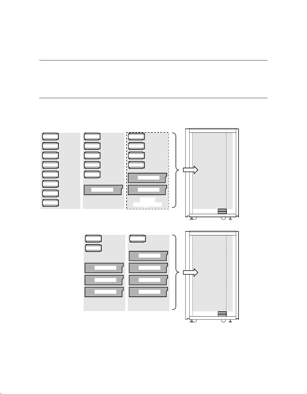
3.10 Expander Cabinet
Additional PCI boxes and storage devices are housed in an expander
cabinet. The same cabinet is used to expand GS160/320 systems and
GS80 systems. Figure 3–12 shows five different PCI and BA356 storage
configurations.
Figure 3–12 BA356 Storage Device Configurations
BA356 (1)
BA356 (1)
BA356 (2)
BA356 (2)
BA356 (3)
BA356 (3)
BA356 (4)
BA356 (4)
BA356 (5)
BA54A PCI (1)
BA356 (6)
BA54A PCI (2)
BA356 (7)
Default
BA356 (8)
Configuration
BA356 (1)
BA356 (2)
BA356 (3)
BA356 (4)
BA356 (5)
BA54A PCI (1) BA54A PCI (2)
BA356 (1)
BA356 (2)
BA356 (3)
BA356 (4)
BA54A PCI (1)
Default
Configuration
BA356 (1)
BA356 (2)
BA54A PCI (3)
BA54A PCI (1)
BA54A PCI (2)
BA356 (1)
BA54A PCI (4)
BA54A PCI (3)
BA54A PCI (1)
BA54A PCI (2)
3-22 AlphaServer GS80/160/320 User's Guide
PK-0646-99
Page 71

Chapter 4
GS80 Rack System Overview
In the rack system, the BA52A system drawer has a QBB containing a
backplane, CPU modules, memory modules, power modules, and I/O riser
modules.
This chapter provides an overview of the BA52A drawer in these sections:
• Rack System Characteristics
• System Drawer Architecture
• System Drawer Modules
GS80 Rack System Overview 4-1
Page 72

4.1 Rack System Characteristics
Table 4–1 lists system drawer characteristics. Table 4–2 lists power and
environmental specifications for the rack system.
Figure 4–1 System Drawer
PK-0633-99
Table 4–1 System Drawer Characteristics
Characteristic Specification
Size
Weight 45 kg (100 lb) maximum
Maximum heat dissipation 1500 w (4910 Btu/hr)
4-2 AlphaServer GS80/160/320 User’s Guide
40 cm H x 45 cm W x 65 cm D (15 in. x 18 in. x
25 in.)
Page 73

Table 4–2 Rack System Characteristics
Electrical
Voltage
Phase Single
Frequency 50–60 Hz
Maximum input
current/circuit
Maximum power
consumption
Environmental
Temperature
Humidity
Altitude
120 VAC (U.S.)
220–240 VAC (Europe)
200–240 VAC (Japan)
16 A (U.S.)
12 A (Europe)
13 A (Japan)
2.4 – 2.8 KVA (U.S.)
5.2 – 5.7 KVA (Europe)
4.8 – 5.7 KVA (Japan)
Operating: 5° to 35°C (41 to 95°F)
Not operating: -40° to 66°C (-40° to 150°F)
Operating: 10% to 90%
Not operating: 10% to 95%
Operating: 0 to 3 km (0 to 10,000 ft)
Not operating: 0 to 12.2 km (0 to 40,000 ft)
GS80 Rack System Overview 4-3
Page 74

4.2 System Drawer Architecture
The system drawer houses a QBB consisting of a backplane that
supports four CPU modules, four memory modules, two power modules
and two I/O riser modules. These modules are identical to those used in
the box systems. The global port is part of the backplane. In a twodrawer system, the drawers are linked by a distribution board.
Figure 4–2 Two-Drawer Block Diagram
System Drawer 1
PCI Box
PCI Box
PCI Box
PCI Box
CPU
I/O GP
MEM
CPU CPU CPU
Switch
MEMMEMMEM
System Drawer 2
CPU
I/O GP
MEM
CPU CPU CPU
Switch
MEMMEMMEM
Distribution
Board
PK-0630-99
4-4 AlphaServer GS80/160/320 User’s Guide
Page 75

The switch that interconnects the CPU modules, memory modules, and I/O riser
modules is built into the system drawer backplane.
In a two-drawer system, the system drawers are linked together through the
global ports and the distribution board. A directory module is required in each
system drawer in a two-drawer system.
GS80 Rack System Overview 4-5
Page 76
4.3 System Drawer Modules
The modules plug into the system drawer backplane. Figure 4–3 shows
a fully populated backplane. Figure 4–4 shows the backplane with no
modules.
Figure 4–3 System Drawer Modules
3
2
1
2
1
4
4
1
2
1
2
5
7
6
PK0619
4-6 AlphaServer GS80/160/320 User’s Guide
Page 77

The CPU, memory, power, and I/O riser modules plug into the backplane
located at the bottom of the system drawer. Callouts in Figure 4–3 point to the
location of the following system drawer modules:
CPU module
➊
Memory module
➋
Directory module
➌
Power modules
➍
Power system manager (PSM) module
➎
I/O riser modules
➏
Clock splitter module
➐
Figure 4–4 System Drawer Backplane
3
2
1
2
1
4
1
2
1
2
5
7
6
PK-0632-99
GS80 Rack System Overview 4-7
Page 78

Page 79

Chapter 5
GS80 Rack System Configuration Rules
This chapter provides configuration rules for the following:
• Rack
• Rack Power System
GS80 Rack System Configuration Rules 5-1
Page 80

5.1 Rack
The cabinet contains a control panel, two AC input boxes, power
subrack with power supplies, vertical mounting rails, a stabilizer, and
a wrist strap for static discharge protection. A rack houses a maximum
of two system drawers.
Figure 5–1 Rack
COMPAQ
AlphaServer GS80
Companion Printer
LA75
5-2 AlphaServer GS80/160/320 User's Guide
digital
PK-0635-99
Page 81

Rack I/O and Storage Configuration Guidelines
• A one-drawer system can have a maximum of two PCI boxes.
• A two-drawer system can have a maximum of four PCI boxes; two PCI boxes
in the rack, and two in an expansion cabinet.
• Both one- and two-drawer systems provide space for one additional PCI box
(
) or one storage shelf (). See Figure 5–2.
Figure 5–2 Rack Optional Configurations
Storage
Optional Configurations
12
PCI Box 2
Drawer 2
H7504 (2)
Rack
PCI Box 1
Drawer 1
H7504 (1)
AC Input Box 2
AC Input Box 1
PK-0657-00
GS80 Rack System Configuration Rules 5-3
Page 82

5.2 Rack Power System
Figure 5–3 shows a two-drawer rack power system: two AC input boxes
and two H7504 power subracks at the bottom of the cabinet. Each
subrack holds three power supplies. The system drawer power cables
connect to the power subrack.
Figure 5–3 Two-Drawer Rack Power System
Power Supply Positions
123
Drawer 1
R
Power Subrack 2
H7504 (2)
R
Power Subrack 1
Redundant Power
R
Supply Location
5-4 AlphaServer GS80/160/320 User's Guide
H7504 (1)
AC Input Box 2
AC Input Box 1
Drawer 2
PK-0638-99
Page 83

About the Power System
• Each rack houses two AC input boxes. AC input box circuit breakers are
accessible from the rear of the cabinet.
• Each system drawer requires one power subrack.
• Each system drawer requires two power supplies.
• Each power subrack holds up to three power supplies. The third power
supply is used for redundancy.
Rack Variants
The H9A20 RETMA cabinet has three variants:
• H9A20-CA, North American (120V)
• H9A20-CB, European (220–240V)
• H9A20-CC, North American and Japanese (200–240V)
GS80 Rack System Configuration Rules 5-5
Page 84

Page 85

Chapter 6
Booting and Installing an
Operating System
This chapter provides basic operating instructions, including powering up the
system and booting the operating system.
Sections in this chapter are:
• Powering Up the System
• Setting Boot Options
• Booting Tru64 UNIX
• Installing Tru64 UNIX
• Booting OpenVMS
• Installing OpenVMS
Booting and Installing an Operating System 6-1
Page 86

6.1 PoweringUptheSystem
Before powering up the system, make sure the keyswitch is off, and
then turn on the circuit breakers in the system cabinet(s) and
expansion cabinets, if necessary. Then, set the keyswitch to On, or
power up the system remotely. The SCM power-up display is shown at
the system management console and the control panel, followed by the
SRM power-up display.
6.1.1 SCM Power-Up Display
Example 6–1 SCM Power-Up Display
SCM_E0> power on
Powering on PCI Box 0
Powering on PCI Box 1
QBB-0 Powering ON
~I~ Testing OCP Switch passed
Power ON Phase INIT
QBB-1 Powering ON
QBB-2 Powering ON
QBB-3 Powering ON
SCM_E0>
Testing SIO Shared RAM(please wait)
Initializing shared ram
Shared RAM Initialized
Powering ON H-Switch
SCM_E0>
I~ HSW4/HPM40 SysEvent: HS_INIT_CD1 Reg0:000F Reg1:AB81
Phase 0
I~ Enable HS Links: 0f
~I~ QbbConf(gp/io/c/m)=fbbfffff Assign=ff SQbb0=00 PQbb=00 SoftQbbId=fedcba98
~I~ SysConfig: 37 13 07 19 07 12 c7 13 37 13 f7 11 f7 13 37 13
SCM_E0>
I~ HSW4/HPM40 SysEvent: LINK0_ON Reg0:000F Reg1:AB81
SCM_E0>
Continuedonnextpage
6-2 AlphaServer GS80/160/320 User’s Guide
Page 87

Example 6–1 SCM Power-Up Display (Continued)
I~ HSW4/HPM40 SysEvent: LINK1_ON Reg0:010F Reg1:AB81
SCM_E0>
I~ HSW4/HPM40 SysEvent: LINK2_ON Reg0:030F Reg1:AB81
SCM_E0>
I~ HSW4/HPM40 SysEvent: LINK3_ON Reg0:070F Reg1:AB81
SCM_E0>
.............................................................................
.........................................................................
SCM_E0> ......................................
The user issues a power on command.
Messages denoted by ~I~ are informational and do not indicate a serious
event. Other types of messages include:
*** – Diagnostic format indicating an error has occurred.
### – Diagnostic format indicating a warning.
~E~ – An error has occurred; power-up continues, but the affected resource
is dropped.
~W~ – An error has occurred; power-up continues, and the affected
resource is questionable.
During the Phase INIT (initialization phase) SROM code is loaded into
each CPU in the system and communication between the power system
manager (PSM) and the CPU is established. Phase 0 follows with local
QBB testing.
Continuedonnextpage
Booting and Installing an Operating System 6-3
Page 88

Example 6–1 SCM Power-Up Display (Continued)
QBB2 Step(s)-012345 Tested
QBB3 Step(s)-012345 Tested
QBB0 Step(s)-012345 Tested
QBB1 Step(s)-012345 Tested
Phase 1
QBB0 IO_MAP0: 000000C101311133
QBB1 IO_MAP1: 0000000000000003
QBB2 IO_MAP2: 0000000000000003
QBB3 IO_MAP3: 000000C001311133
~I~ QbbConf(gp/io/c/m)=fbbfffff Assign=ff SQbb0=00 PQbb=00 SoftQbbId=fedcba98
~I~ SysConfig: 37 13 07 19 07 12 c7 13 37 13 f7 11 f7 13 37 13
SCM_E0>
QBB1 now Testing Step-6
QBB1 now Testing Step-7
QBB1 now Testing Step-8
QBB1 now Testing Step-9
QBB1 now Testing Step-A
QBB2 now Testing Step-6
QBB2 now Testing Step-7
QBB3 now Testing Step-6
QBB3 now Testing Step-7
QBB3 now Testing Step-8
QBB3 now Testing Step-9
QBB3 now Testing Step-A.
QBB0 now Testing Step-6
QBB1 Step(s)-A B Tested
QBB2 Step(s)-789AB Tested
QBB3 Step(s)-A B Tested.
QBB0 now Testing Step-7.
QBB0 now Testing Step-8..
QBB0 now Testing Step-9...
QBB0 now Testing Step-A..
QBB0 now Testing Step-7.
QBB0 now Testing Step-8...
QBB0 now Testing Step-9..
QBB0 now Testing Step-A..
QBB0 now Testing Step-7.
QBB0 now Testing Step-8...
QBB0 now Testing Step-9...
QBB0 now Testing Step-A..
QBB0 now Testing Step-B..
Phase 2
QBB0 IO_MAP0: 000000C101311133
QBB1 IO_MAP1: 0000000000000003
QBB2 IO_MAP2: 0000000000000003
QBB3 IO_MAP3: 000000C001311133
~I~ QbbConf(gp/io/c/m)=fbbfffff Assign=ff SQbb0=00 PQbb=00 SoftQbbId=fedcba98
~I~ SysConfig: 37 13 07 19 07 12 c7 13 37 13 f7 11 f7 13 37 13
SCM_E0>
QBB1 now Testing Step-C
QBB2 now Testing Step-C
QBB3 now Testing Step-C
QBB0 Step(s)-B C Tested...
6-4 AlphaServer GS80/160/320 User’s Guide
Page 89

Example 6–1 SCM Power-Up Display (Continued)
Phase 3
~I~ QbbConf(gp/io/c/m)=fbbfffff Assign=ff SQbb0=00 PQbb=00 SoftQbbId=fedcba98
~I~ SysConfig: 37 13 07 19 07 12 c7 13 37 13 f7 11 f7 13 37 13
SCM_E0>
QBB0 now Testing Step-D
QBB1 now Testing Step-D
QBB2 now Testing Step-D
QBB3 now Testing Step-D.............
QBB0 IO_MAP0: 000000C101311133
QBB1 IO_MAP1: 0000000000000003
QBB2 IO_MAP2: 0000000000000003
QBB3 IO_MAP3: 000000C001311133
Phase 4
~I~ QbbConf(gp/io/c/m)=fbbfffff Assign=ff SQbb0=00 PQbb=00 SoftQbbId=fedcba98
QBB0 unloading console across port0 from PCI Box-1
Console COM1 from master PCI Box-0
~I~ SysConfig: 37 13 07 19 07 12 c7 13 37 13 f7 11 f7 13 37 13
Retrieving FRU information for Shared RAM...
SCM_E0>
QBB0 now Testing Step-E..
Power On Complete
Returning to system COM1 port
Phase 1. The primary CPU, selected by the SCM in phase 0, tests each
QBB in the system.
Phase 2. Secondary CPUs are tested to ensure cache coherency.
Phase 3. The tests ensure that each CPU can access each memory array in
the system.
Phase 4. The primary CPU unloads the PAL/console code from the flash
ROM on the standard I/O module into memory.
Control of the remainder of power-up is passed to the console firmware.
See Section 6.1.2.
Booting and Installing an Operating System 6-5
Page 90

6.1.2 SRM Power-Up Display
Following the initial SCM power-up and the five test phases, the SRM
console takes control of the remaining portion of system power-up.
Example 6–2 SRM Power-Up Display
System Primary QBB0 : 0
System Primary CPU : 0 on QBB0
Par hrd/sft CPU Mem IOR3 IOR2 IOR1 IOR0 GP QBB Dir PS Temp
QBB# 3210 3210 (pci_box.rio) Mod BP Mod 321 (:C)
(-) 0/30 ---P PP --.- --.- Px.x P1.0 P P P PPP 26.5
(-) 1/31 -P-P PP --.- --.- --.- --.- P P P PPP 29.0
(-) 2/32 --P- --P- --.- --.- --.- --.- P P P PP- 25.0
(-) 3/33 ---P -P-- --.- --.- Px.x P0.0 P P P PP- 27.0
HSwitch Type Cables76543210 Temp(:C)
HPM40 4-port ----EEEE 29.0
PCI Rise1-1 Rise1-0 Rise0-1 Rise0-0 RIO PS Temp
Cab7654 321 7654 321 10 21 (:C)
10 ---- --- ---- --S -* P- 27.5
11 ---- --- --L- LMS -* PP 27.0
OpenVMS PALcode V1.75-1, Tru64 UNIX PALcode V1.68-1
system = QBB0123 +HS
QBB 0 = CPU 0 + Mem 0 1 + Dir + IOP + PCA 0 + GP (Hard QBB 0)
QBB 1 = CPU 0 2 + Mem 0 1 + Dir + IOP + PCA + GP (Hard QBB 1)
QBB 2 = CPU 1 + Mem 1 + Dir + IOP + PCA + GP (Hard QBB 2)
QBB 3 = CPU 0 + Mem 2 + Dir + IOP + PCA 0 + GP (Hard QBB 3)
shared RAM version is 1.3
hose 24 has a standard I/O module
starting console on CPU 0
initialized idle PCB
initializing semaphores
initializing heap
initial heap 2c0c0
memory low limit = 1f2000
heap = 2c0c0, 1ffc0
initializing driver structures
initializing idle process PID
initializing file system
initializing timer data structures
lowering IPL
6-6 AlphaServer GS80/160/320 User’s Guide
Page 91

A snapshot of the system environment is displayed. See Section 8.7.3 for
more information.
PALcode is loaded and started.
The size of the system is determined and mapped. This system has four
QBBs and five CPUs.
Continuedonnextpage
Booting and Installing an Operating System 6-7
Page 92

Example 6–2 SRM Power-Up Display (Continued)
CPU 0 speed is 731 MHz
create dead_eater
create poll
create timer
create powerup
access NVRAM
QBB 0 memory, 1 GB
QBB 1 memory, 1 GB
QBB 2 memory, 512 MB
QBB 3 memory, 512 MB
total memory, 3 GB
copying PALcode to 103ffe8000
copying PALcode to 201ffe8000
copying PALcode to 301ffe8000
probe I/O subsystem
probing hose 0, PCI
probing PCI-to-ISA bridge, bus 1
bus 1, slot 0 -- dva—Floppy
bus 0, slot 1 -- pka—QLogic ISP10x0
bus 0, slot 2 -- vga—ELSA GLoria Synergy
bus 0, slot 3 -- pkb—QLogic ISP10x0
bus 0, slot 15 -- dqa—Acer Labs M1543C IDE
bus 0, slot 15 -- dqb—Acer Labs M1543C IDE
probing hose 1, PCI
bus 0, slot 5 -- ewa—DE500-BA Network Controller
probing hose 24, PCI
probing PCI-to-ISA bridge, bus 1
bus 1, slot 0 -- dvb—Floppy
bus 0, slot 1 -- pkc—QLogic ISP10x0
bus 0, slot 15 -- dqc—Acer Labs M1543C IDE
bus 0, slot 15 -- dqd—Acer Labs M1543C IDE
probing hose 25, PCI
starting drivers
*** keyboard not plugged in...
entering idle loop
initializing keyboard
*** keyboard not plugged in...
starting console on CPU 4
initialized idle PCB
initializing idle process PID
lowering IPL
CPU 4 speed is 731 MHz
create powerup
starting console on CPU 6
initialized idle PCB
initializing idle process PID
lowering IPL
CPU 6 speed is 731 MHz
create powerup
starting console on CPU 9
initialized idle PCB
initializing idle process PID
lowering IPL
6-8 AlphaServer GS80/160/320 User’s Guide
Continuedonnextpage
Page 93

Example 6–2 SRM Power-Up Display (Continued)
CPU 9 speed is 731 MHz
create powerup
starting console on CPU 12
initialized idle PCB
initializing idle process PID
lowering IPL
CPU 12 speed is 731 MHz
create powerup
initializing pka pkb pkc ewa dqa dqb dqc dqd
initializing GCT/FRU at 1f2000
AlphaServer Console X5.7-6290, built on Feb 4 2000 at 01:41:06
P00>>>
Distributed memory is sized and mapped.
The I/O subsystem is mapped.
Each secondary CPU starts the console, is initialized and ready to join the
multiprocessor environment.
The SRM console prompt is displayed.
Booting and Installing an Operating System 6-9
Page 94

6.2 Setting Boot Options
You can set a default boot device, boot flags, and network boot
protocols for Tru64 UNIX or OpenVMS using the SRM set command
with environment variables. Once these environment variables are set,
the boot command defaults to the stored values. You can override the
stored values for the current boot session by entering parameters on
the boot command line.
The SRM boot-related environment variables are listed below and described in
the following sections:
bootdef_dev
boot_file Specifies a default file name to be used for booting when
boot_osflags Defines parameters to enable specific functions during the
ei*0_inet_init or
ew*0_inet_init
ei*0_protocols or
ew*0_protocols
Defines a default boot device.
no file name is specified by the boot command.
boot process.
Determines whether the interface's internal Internet
database is initialized from nvram or from a network
server (through the bootp protocol). Set this environment
variableifyouarebootingTru64 UNIX from a RIS server.
Defines a default network boot protocol (bootp or mop).
6.2.1 Bootdef_dev
The bootdef_dev environment variable specifies one or more devices
from which to boot the operating system. When more than one device is
specified, the system searches in the order listed and boots from the
first device.
Enter the show bootdef_dev command to display the current default boot
device. Enter the show device command for a list of all devices in the system.
6-10 AlphaServer GS80/160/320 User’s Guide
Page 95

The syntax is:
set bootdef_dev boot_device
boot_device The name of the device on which the system software has
been loaded. To specify more than one device, separate the
names with commas.
Example
In this example, two boot devices are specified. The system will try booting
from dkb0 and, if unsuccessful, will boot from dka0.
P00>>> set bootdef_dev dkb0, dka0
NOTE: When you set the bootdef_dev environment variable, it is recommend-
ed that you set the operating system boot parameters as well, using the
set boot_osflags command.
6.2.2 Boot_file
The boot_file environment variable specifies the default file name to be
used for booting when no file name is specified by the boot command.
The syntax is:
set boot_file filename
Example
In this example, a boot file is specified for booting OpenVMS from the
InfoServer. APB_0712 is the file name of the APB program used for the
initial system load (ISL) boot program.
P00>>> set boot_file apb_0712
Booting and Installing an Operating System 6-11
Page 96

6.2.3 Boot_osflags
The boot_osflags environment variable sets the default boot flags and,
for OpenVMS,arootnumber.
Boot flags contain information used by the operating system to determine some
aspects of a system bootstrap. Under normal circumstances, you can use the
default boot flag settings.
To change the boot flags for the current boot only, use the flags_value argument
with the boot command.
The syntax is:
set boot_osflags flags_value
The flags_value argument is specific to the operating system.
Tru64 UNIX Systems
Tru64 UNIX systems take a single ASCII character as the flags_value
argument.
Load operating system software from the specified boot device
a
(autoboot). Boot to multiuser mode.
Prompt for the name of a file to load and other options (boot
i
interactively). Boot to single-user mode.
Stop in single-user mode. Boots /vmunix to single-user mode and stops
s
at the # (root) prompt.
D Full dump; implies “s”aswell.Bydefault,ifTru64 UNIX crashes, it
completes a partial memory dump. Specifying “D” forces a full dump at
system crash.
6-12 AlphaServer GS80/160/320 User’s Guide
Page 97

OpenVMS Systems
OpenVMS systems require an ordered pair as the flags_value argument:
root_number and boot_flags.
root_number Directory number of the system disk on which OpenVMS files
are located. For example:
root_number Root Directory
0 (default) [SYS0.SYSEXE]
1 [SYS1.SYSEXE]
2 [SYS2.SYSEXE]
3 [SYS3.SYSEXE]
boot_flags The hexadecimal value of the bit number or numbers set. To
specify multiple boot flags, add the flag values (logical OR).
For example, the flag value 10080 executes both the 80 and
10000 flag settings. See Table 6–1.
Table 6–1 OpenVMS Boot Flag Settings
Flags_Value Bit Number Meaning
1 0 Bootstrap conversationally (enables you to
modify SYSGEN parameters in SYSBOOT).
21MapXDELTAtoarunningsystem.
4 2 Stop at initial system breakpoint.
8 3 Perform diagnostic bootstrap.
10 4 Stop at the bootstrap breakpoints.
20 5 Omit header from secondary bootstrap image.
80 7 Prompt for the name of the secondary bootstrap
file.
100 8 Halt before secondary bootstrap.
10000 16 Display debug messages during booting.
20000 17 Display user messages during booting.
Continued on next page
Booting and Installing an Operating System 6-13
Page 98

Example
In the following Tru64 UNIX example, the boot flags are set to autoboot the
system to multiuser mode when you enter the boot command.
P00>>> set boot_osflags a
In the following OpenVMS example, root_number is set to 2 and boot_flags is set
to 1. With this setting, the system will boot from root directory SYS2.SYSEXE
to the SYSBOOT prompt when you enter the boot command.
P00>>> set boot_osflags 2,1
In the following OpenVMS example, root_number is set to 0 and boot_flags is
set to 80. With this setting, you are prompted for the name of the secondary
bootstrap file when you enter the boot command.
P00>>> set boot_osflags 0,80
6.2.4 ei*0_inet_init or ew*0_inet_init
The ei*0_inet_init or ew*0_inet_init environment variable determines
whether the interface's internal Internet database is initialized from
nvram or from a network server (through the bootp protocol).
Legal values are nvram and bootp. The default value is bootp.Setthis
environment variable if you are booting Tru64 UNIX from a RIS server.
To list the network devices on your system, enter the show device command.
The Ethernet controllers start with the letters “ei” or “ew,” for example, ewa0.
The third letter is the adapter ID for the specific Ethernet controller. Replace
the asterisk (*) with the adapter ID letter when entering the command.
The syntax is:
set ei*0_inet_init value or
set ew*0_inet_init value
Example
P00>>> set eia0_inet_init bootp
6-14 AlphaServer GS80/160/320 User’s Guide
Page 99

6.2.5 ei*0_protocols or ew*0_protocols
The ei*0_protocols or ew*0_protocols environment variable sets
network protocols for booting and other functions.
To list the network devices on your system, enter the show device command.
The Ethernet controllers start with the letters “ei” or “ew,” for example, eia0.
The third letter is the adapter ID for the specific Ethernet controller. Replace
the asterisk (*) with the adapter ID letter when entering the command.
The syntax is:
set ei*0_protocols protocol_value or
set ew*0_protocols protocol_value
The options for protocol_value are:
mop (default) Sets the network protocol to mop (Maintenance Operations
Protocol), the setting typically used with the OpenVMS
operating system.
bootp Sets the network protocol to bootp, the setting typically used
with the Tru64 UNIX operating system.
bootp,mop When both are listed, the system attempts to use the mop
protocol first, regardless of which is listed first. If not
successful, it then attempts the bootp protocol.
Example
P00>>> show device
.
.
.
eia0.0.0.1001.0 EIA0 08-00-2B-3E-BC-B5
eib0.0.0.12.0 EIB0 00-00-C0-33-E0-0D
eic0.0.0.13.0 EIC0 08-00-2B-E6-4B-F3
.
.
.
P00>>> set eia0_protocols bootp
P00>>> show eia0_protocols
eia0_protocols bootp
Booting and Installing an Operating System 6-15
Page 100

6.3 Booting Tru64 UNIX
Tru64 UNIX can be booted from a DVD or CD-ROM on a local drive,
from a local SCSI disk, or from a server.
Example 6–3 Booting Tru64 UNIX from a Local SCSI Disk
P00>>> sho dev
dka0.0.0.1.0 DKA0 RZ2ED-LS 0306
dka100.1.0.1.1 DKA100 RZ2ED-LS 0306
dka200.2.0.1.1 DKA200 RZ2DD-LS 0306
dka300.3.0.1.1 DKA300 RZ2DD-LS 0306
dkc0.0.0.1.0 DKC0 RZ2DD-LS 0306
dkc100.1.0.1.0 DKC100 RZ2DD-LS 0306
dkc200.2.0.1.0 DKC200 RZ2DD-LS 0306
dkc300.3.0.1.0 DKC300 RZ2DD-LS 0306
dqa0.0.0.15.0 DQA0 TOSHIBA CD-ROM XM-6202B 1110
dva0.0.0.1000.0 DVA0
P00>>> boot
(boot dka0.0.0.1.0 -flags a)
block 0 of dka0.0.0.1.0 is a valid boot block
reading 13 blocks from dka0.0.0.1.0
bootstrap code read in
base = 2e6000, image_start = 0, image_bytes = 1a00
initializing HWRPB at 2000
initializing page table at 17fbda000
initializing machine state
setting affinity to the primary CPU
jumping to bootstrap code
Tru64 UNIX boot - Wed Sep 8 20:59:58 EDT 1999
Loading vmunix ...
Loading at 0xfffffc0000430000
Sizes:
text = 4800560
data = 903872
bss = 1412480
Starting at 0xfffffc00007790d0
Loading vmunix symbol table ... [1330800 bytes]
Alpha boot: available memory from 0x93de000 to 0x3180000000
Digital Tru64 UNIX V4.0G-1 (Rev. 1398); Thu Oct 21 13:34:00 EDT 1999
physical memory = 24572.00 megabytes.
available memory = 24140.65 megabytes.
using 94344 buffers containing 737.06 megabytes of memory
Master cpu at slot 0.
6-16 AlphaServer GS80/160/320 User’s Guide
 Loading...