

Page 1
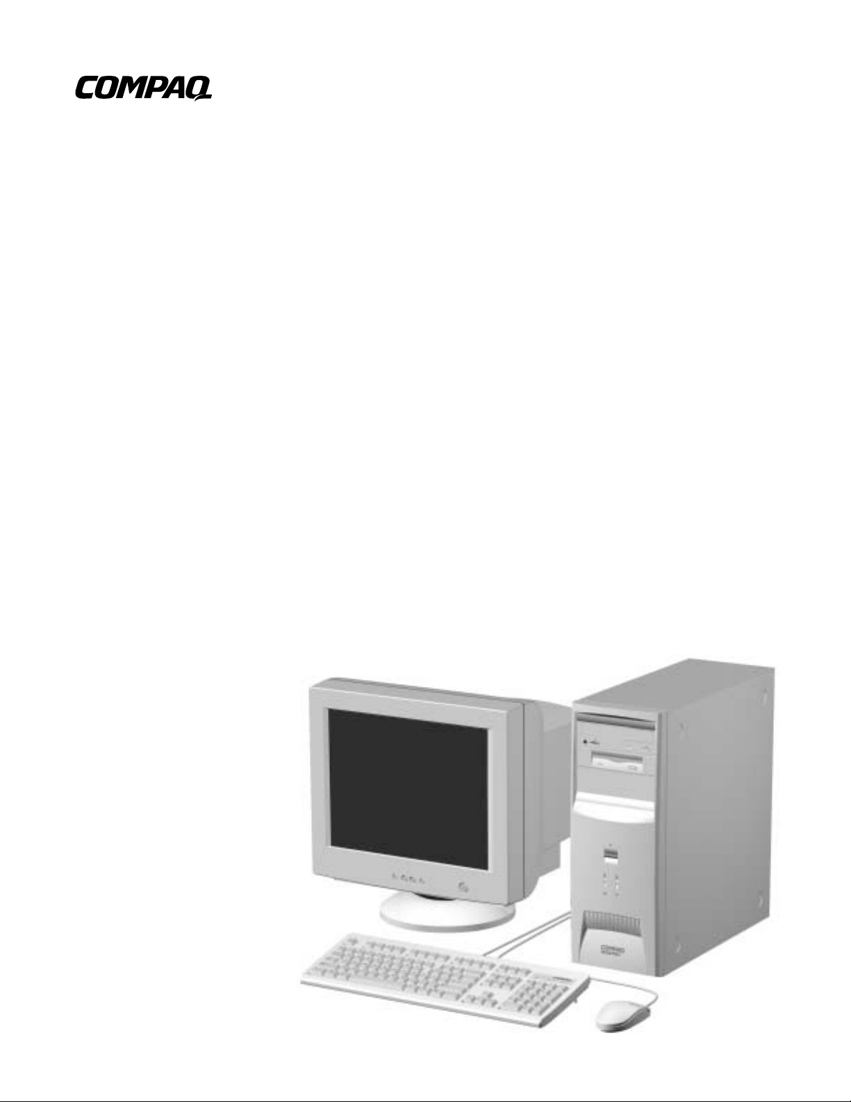
Maintenance &
Service Guide
Compaq Deskpro EX and Deskpro EXS
Series of Personal Computers
Minitower Models
Page 2

Maintenance &
Service Guide
Compaq Deskpro EX and Deskpro EXS
Series of Personal Computers
Minitower Models
Page 3
Notice
© 2000 Compaq Computer Co rp oration. Except for use in connect ion with the accompanying Compaq product, no part of
this guide may be photocopied or reproduced in any form without prior written consent from Compaq Computer
Corporation.
COMPAQ, the Compaq logo, and Deskpro Registered in U.S. Patent and Trademark Offi ce are t r ademarks of Compaq
Information Technologies Group, L.P.
Microsoft, Windows, Windows NT, and other names of Microsoft products referenced herein are trademarks or registered
trademarks of Microsoft Corporation.
Intel and Pentium are registered trademarks of Intel Corporation. Celeron and MMX are trademarks of Intel Corporation.
All other product names mentioned herein may be trademarks or registered trademarks of their respective companies.
Compaq shall not be liable for technical or editorial errors or omissions contained herein. The information in this document
is subject to change without notice.
THE INFORMATION IN THIS PUBLICATION IS PROVIDED "AS IS" WITHOUT WARRANTY OF ANY KIND.
THE ENTIRE RISK ARISING OUT OF THE USE OF THIS INFORMATION REMAINS WITH RECIPIENT. IN NO
EVENT SHALL COMPAQ BE LIABLE FOR ANY DIRECT, CONSEQUENTIAL, INCIDENTAL, SPECIAL,
PUNITIVE OR OTHER DAMAGES WHATSOEVER (INCLUDING WITHOUT LIMITATION, DAMAGES FOR
LOSS OF BUSINESS PROFITS, BUSINESS INTERRUPTION OR LOSS OF BUSINESS INFORMATION), EVEN IF
COMPAQ HAS BEEN ADVISED OF THE POSSIBILITY OF SUCH DAMAGES AND WHETHER IN AN ACTION
OF CONTRACT OR TORT, INCLUDING NEGLIGENCE.
The limited warranties for Compaq pro ducts are exclusively set forth in the documentation accompan ying such
products. Nothing herein shou l d be con strued as constituting a further or additional warranty.
The following words and symbols mark special messages throughout this guide:
WARNING:
to follow directions could result in bodily harm or loss of life.
CAUTION:
follow directions could result in damage to equipment or loss of
information.
Text set off in this manner indicates that failure
Text set off in this manner indicates that failure to
Maintenance & Service Guide
Compaq Deskpro EX and Deskpro EXS Series of P ersonal Computers
Minitower Models
First Edition (September 2000)
Part Number 201856-001
Spare Parts Number 215879-001
Compaq Computer Corporation
Page 4

preface
About This Guide
Symbols and Conventions.........................................................................................................vii
Technician Notes.......................................................................................................................vii
Locating Additional Information .............................................................................................viii
chapter 1
Product Description
1.1 Computer Features.......................................................................................................... 1-2
1.1.1 Front Panel Controls and LEDs ......................................................................... 1-2
1.1.2 Rear Panel Connectors....................................................................................... 1-3
1.1.3 Drive Positions................................................................................................... 1-4
1.2 Serial Number Location.................................................................................................. 1-5
chapter 2
Spare Parts
2.1 System Unit .................................................................................................................... 2-2
2.2 Mass Storage Devices..................................................................................................... 2-3
2.3 Cables ............................................................................................................................. 2-4
2.4 Standard, Memory, and Expansion Boards .................................................................... 2-5
2.5 Miscellaneous Plastics Kit.............................................................................................. 2-6
2.6 Keyboards (not illustrated)............................................................................................. 2-7
2.7 Miscellaneous Screw Kit (not illustrated)....................................................................... 2-7
2.8 Miscellaneous Parts (not illustrated)............................................................................... 2-8
2.9 Shipping Boxes (not illustrated)..................................................................................... 2-8
2.10 Documentation and Software (not illustrated)................................................................ 2-8
ONTENTS
C
chapter 3
Removal and Replacement Preliminaries
3.1 Electrostatic Discharge Information............................................................................... 3-1
3.1.1 Generating Static................................................................................................ 3-1
3.1.2 Preventing Electrostatic Damage to Equipment................................................. 3-2
3.1.3 Personal Grounding Methods and Equipment ................................................... 3-2
3.1.4 Grounding Workstations.................................................................................... 3-2
3.1.5 Recommended Materials and Equipment........................................................... 3-3
3.2 Routine Care................................................................................................................... 3-3
3.2.1 General Cleaning Safety Precautions................................................................. 3-3
3.2.2 Cleaning the Computer Case.............................................................................. 3-4
3.2.3 Cleaning the Keyboard....................................................................................... 3-4
3.2.4 Cleaning the Monitor ......................................................................................... 3-4
3.2.5 Cleaning the Mouse............................................................................................ 3-5
Contents iii
Page 5

3.3 Service Considerations ................................................................................................... 3-5
3.3.1 Power Supply Fan.............................................................................................. 3-5
3.3.2 Tools and Software Requirements ..................................................................... 3-5
3.3.3 Screws................................................................................................................ 3-5
3.3.4 Cables and Connectors....................................................................................... 3-6
3.3.5 Hard Drives........................................................................................................ 3-6
3.3.6 Lithium Coin Cell Battery.................................................................................. 3-6
chapter 4
Removal and Replacement Procedures
4.1 Disassembly Sequence Chart.......................................................................................... 4-1
4.2 Disassembly Preparation................................................................................................. 4-2
4.3 Feet Installation .............................................................................................................. 4-3
4.4 Cable Lock...................................................................................................................... 4-4
4.5 Access Panel................................................................................................................... 4-5
4.6 Front Bezel ..................................................................................................................... 4-6
4.7 Power Button.................................................................................................................. 4-7
4.8 Subpanel and Bezel Blanks............................................................................................. 4-8
4.9 Power Switch Assembly................................................................................................. 4-9
4.10 Mass Storage Devices................................................................................................... 4-10
4.10.1 Removing an Internal 3.5-Inch Hard Drive ..................................................... 4-12
4.10.2 Removing an External 5.25-Inch Drive........................................................... 4-13
4.10.3 Removing an External 3.5-Inch Drive............................................................. 4-14
4.11 Expansion Boards......................................................................................................... 4-16
4.11.1 Expansion Board Slots..................................................................................... 4-16
4.11.2 Removing a PCI Expansion Board................................................................... 4-17
4.11.3 Installing a PCI Expansion Board.................................................................... 4-18
4.12 System Memory............................................................................................................ 4-20
4.13 Graphics Cards..............................................................................................................4-22
4.13.1 Graphics Performance Accelerator (GPA)/AGP Inline Memory
Module (AIMM) Card with a Type I Retention Mechanism.................................... 4-22
4.13.2 AGP Card with a Type I Retention Mechanism............................................... 4-25
4.13.3 GPA/AIMM Card with a Type 2 Retention Mechanism.................................. 4-26
4.13.4 AGP Card with a Type 2 Retention Mechanism.............................................. 4-27
4.13.5 Standard AGP Expansion Card........................................................................ 4-28
4.14 Processor....................................................................................................................... 4-29
4.15 System Board................................................................................................................4-31
4.16 Battery .......................................................................................................................... 4-32
4.17 Chassis Fan Assembly.................................................................................................. 4-33
4.18 Power Supply................................................................................................................4-34
chapter 5
Connectors & Jumpers
iv Contents
5.1 System Board.................................................................................................................. 5-1
5.1.1 Connectors and Jumpers .................................................................................... 5-1
5.1.2 Clearing CMOS.................................................................................................. 5-2
5.1.3 Disabling or Clearing the Power-On and Setup Passwords ............................... 5-3
5.2 Hard Drive Jumper Settings............................................................................................ 5-4
5.2.1 Seagate, Quantum, and Western Digital ............................................................ 5-4
5.2.2 Maxtor................................................................................................................ 5-5
Page 6

chapter 6
Specifications
6.1 Specifications.................................................................................................................. 6-1
6.1.1 System................................................................................................................ 6-1
6.1.2 System Interrupts ............................................................................................... 6-2
6.1.3 System DMA...................................................................................................... 6-2
6.1.4 ICH Fixed I/O Registers..................................................................................... 6-3
6.1.5 System Memory Map......................................................................................... 6-5
6.2 Drives.............................................................................................................................. 6-6
6.2.1 1.44-MB Diskette Drive..................................................................................... 6-6
6.2.2 Ultra ATA Hard Drives...................................................................................... 6-7
6.2.3 CD-ROM Drives................................................................................................ 6-8
6.3 Compaq Keyboard.......................................................................................................... 6-9
6.4 Scroll Mouse................................................................................................................... 6-9
6.5 Supported Graphics Resolutions................................................................................... 6-10
6.5.1 Intel 3D Graphics............................................................................................. 6-10
6.5.2 nVIDIA M64 Pro ............................................................................................. 6-10
index ..............................................................................................................................................
I-1
Contents v
Page 7
preface
BOUT THIS GUIDE
A
This Maintenance & Service Guide is a troubleshooting and repair guide that can be used
for reference when servicing the Compaq Deskpro EX Series of Personal Computers
Minitower Model. Only authorized technicians trained by Compaq should attempt to
repair this equipment.
Compaq Computer Corporation reserves the right to make changes to the these models
without notice.
Symbols and Conventions
The following text and symbols mark special messages throughout this guide:
WARNING: Text set off in this manner indicates that failure to follow directions in the warning could
!
result in bodily harm or loss of life.
CAUTION: Text set off in this manner indicates that failure to follow directions could result in
damage to equipment or loss of data.
Text set off in this manner presents commentary, sidelights, clarifying information, or
✎
specific instructions.
Technician Notes
WARNING: Only authorized technicians trained by Compaq should attempt to repair this equipment.
!
All troubleshooting and repair procedures are detailed to allow only subassembly/module level repair.
Because of the complexity of the individual boards and subassemblies, no one should attempt to make
repairs at the component level or to make modifications to any printed wiring board. Improper repairs
can create a safety hazard. Any indications of component replacement or printed wiring board
modifications may void any warranty.
WARNING: To reduce the risk of electric shock or damage to the equipment:
!
• Do not disable the power grounding plug. The grounding plug is an important safety feature.
• Plug the power cord into a grounded (earthed) electrical outlet that is easily accessible at all
• Disconnect the power from the computer by unplugging the power cord either from the
CAUTION: To properly ventilate your system, you must provide at least 3 inches (7.6 cm) of
clearance at the front and back of the computer.
times.
electrical outlet or the computer.
Compaq Deskpro EX and Deskpro EXS Series of Personal Computers vii
Page 8

Locating Additional Information
The following documentation is availab le to suppo rt the se produc ts :
■ User Documentation
■ Technical Training Guides
■ Compaq Service Advisories and Bulletins
■ Compaq QuickFind
■ Technical Reference Guide
■ Compaq Quick Reference Guide
■ Compaq Service Reference Guide
■ Compaq Quick Troubleshooting Guide
viii About This Guide
Page 9
chapter
1
RODUCT DESCRIPTION
P
This chapter describes the model offerings and features of the Compaq Deskpro EX Series
of Personal Computers Minitower Model.
Compaq Deskpro EX and Deskpro EXS Series of Personal Computers 1-1
Page 10
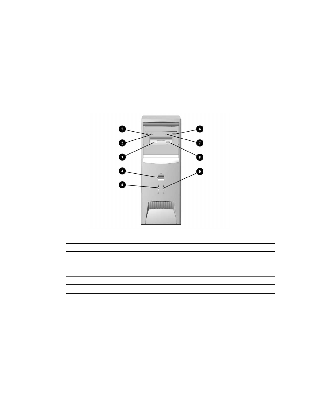
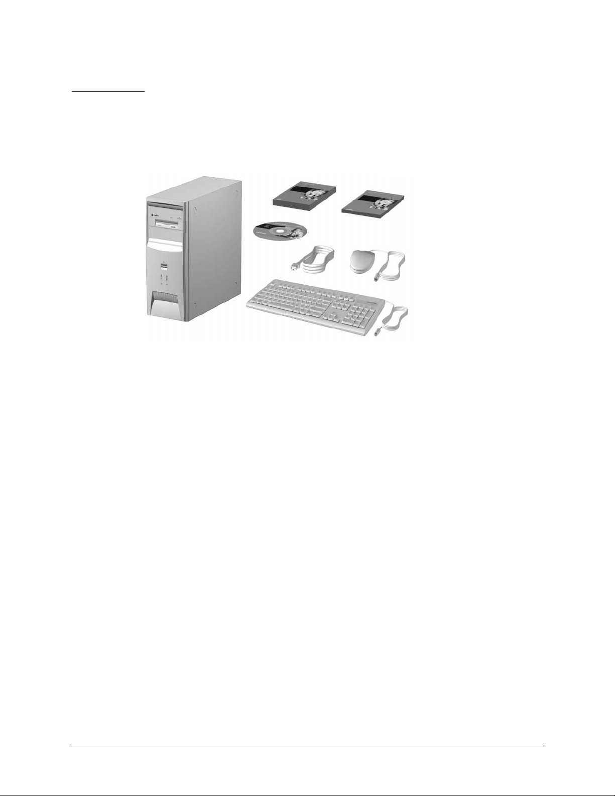
1.1 Computer Features
Compaq Deskpro EX Series of Personal Computers Minitower Model ships with a mouse
and keyboard. Some models are also equipped with a CD-ROM drive. A Compaq color
monitor or other compatible monitor does not ship with the computer.
1.1.1 Front Panel Controls and LEDs
Ref. Component/Function Ref. Component/Function
Stereo Headphone Jack*
1
Headphone Volume Control*
2
Diskette Drive Activity Light
3
Dual-State Power Button
4
Power-On Light
5
*CD-ROM models only.
**Flashes when an ATAPI device, such as the hard drive, is active.
1-2 Product Description
6
7
8
9
CD-ROM Eject Button*
CD-ROM Drive Busy Indicator*
Diskette Eject Button
Drive Activity Light**
Page 11
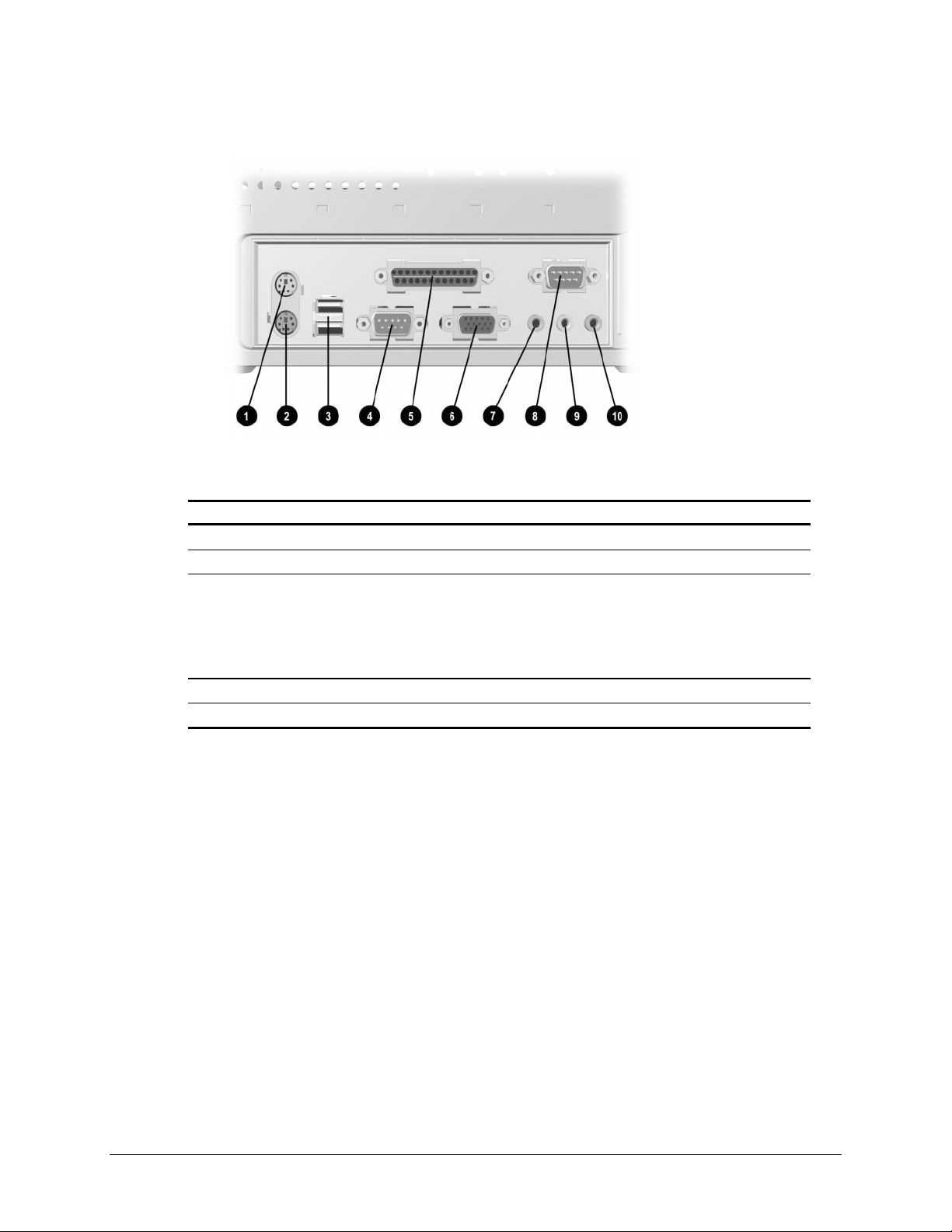
1.1.2 Rear Panel Connectors
Ref. Component Ref. Component
Mouse Connector
1
Keyboard Connector
2
Universal Serial Bus (USB)
3
Connectors (2) (connects the
computer to any USB peripheral
while the computer is operating; is
a fully functional plug and play
connector)
Serial Connector
4
Parallel Port Connector
5
6
7
8
9
:
Monitor Connector
Headphone/Line-Out Audio Connector
Serial Connector
Line-In Audio Connector
Microphone Connector
Compaq Deskpro EX and Deskpro EXS Series of Personal Computers 1-3
Page 12
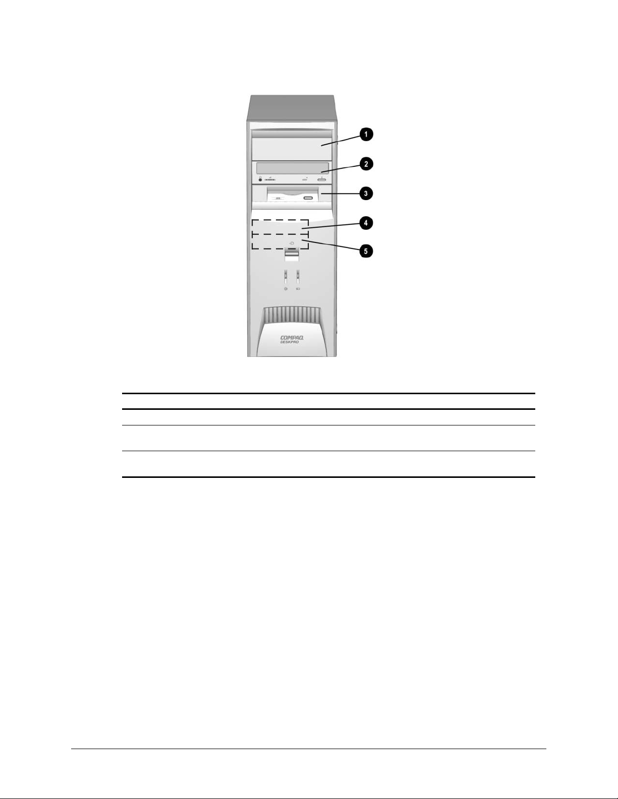
1.1.3 Drive Positions
Reference Drive Bay Configuration
1, 2
3
4, 5
1, 2 Two standard 5.25-inch, half-height bays for optional drives
3
4, 5
One standard 3.5-inch, 1.44-MB diskette drive mounted with a drive
adapter into a 5.25-inch bay
Two standard 3.5-inch drive bays; Bay 4 contains the preinstalled hard
drive; Bay 5 is available for an optional hard drive
Drive bay numbers are stamped on the chassis.
To verify the type and size of the mass storage devices installed in the computer, run F10
Compaq Computer Setup.
1-4 Product Description
Page 13
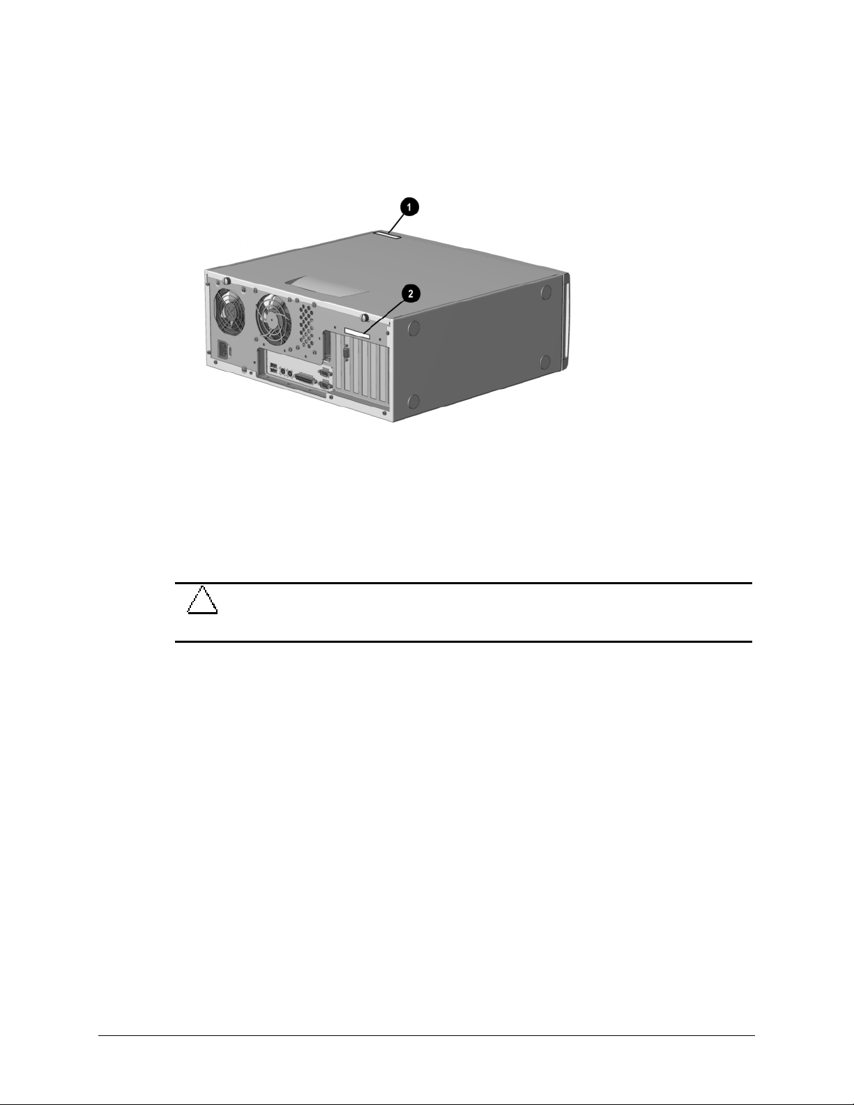
1.2 Serial Number Location
The serial number and model information label is located on the access panel of the
unit 1. A second barcode label is located on the rear of the unit 2.
For the purpose of AssetControl, the serial number is embedded in CMOS and in the
EEPROM on the system board and may be accessed through Diagnostics for Windows.
If the system board is replaced with a spare part from Compaq, the invalid serial
number condition will be recognized during POST. The original serial number
must then be reentered through Computer Setup. Refer to the Software Reference
Guide for more information.
CAUTION: A system board borrowed from another computer is recognized as a valid serial
number and will create a mismatch between the serial number label and the electronic serial
number.
The computer serial number should be provided to Compaq when requesting information
or ordering spare parts.
Compaq Deskpro EX and Deskpro EXS Series of Personal Computers 1-5
Page 14
chapter
PARE PARTS
S
2
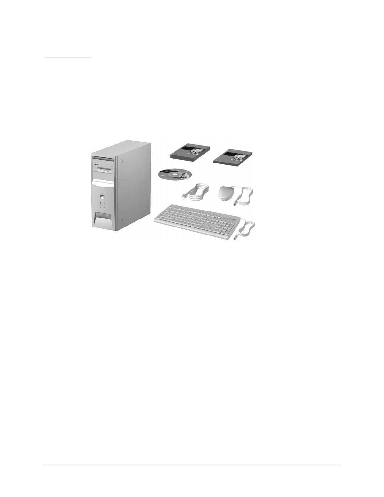
Compaq Deskpro EX and Deskpro EXS Series of Personal Computers 2-1
Page 15
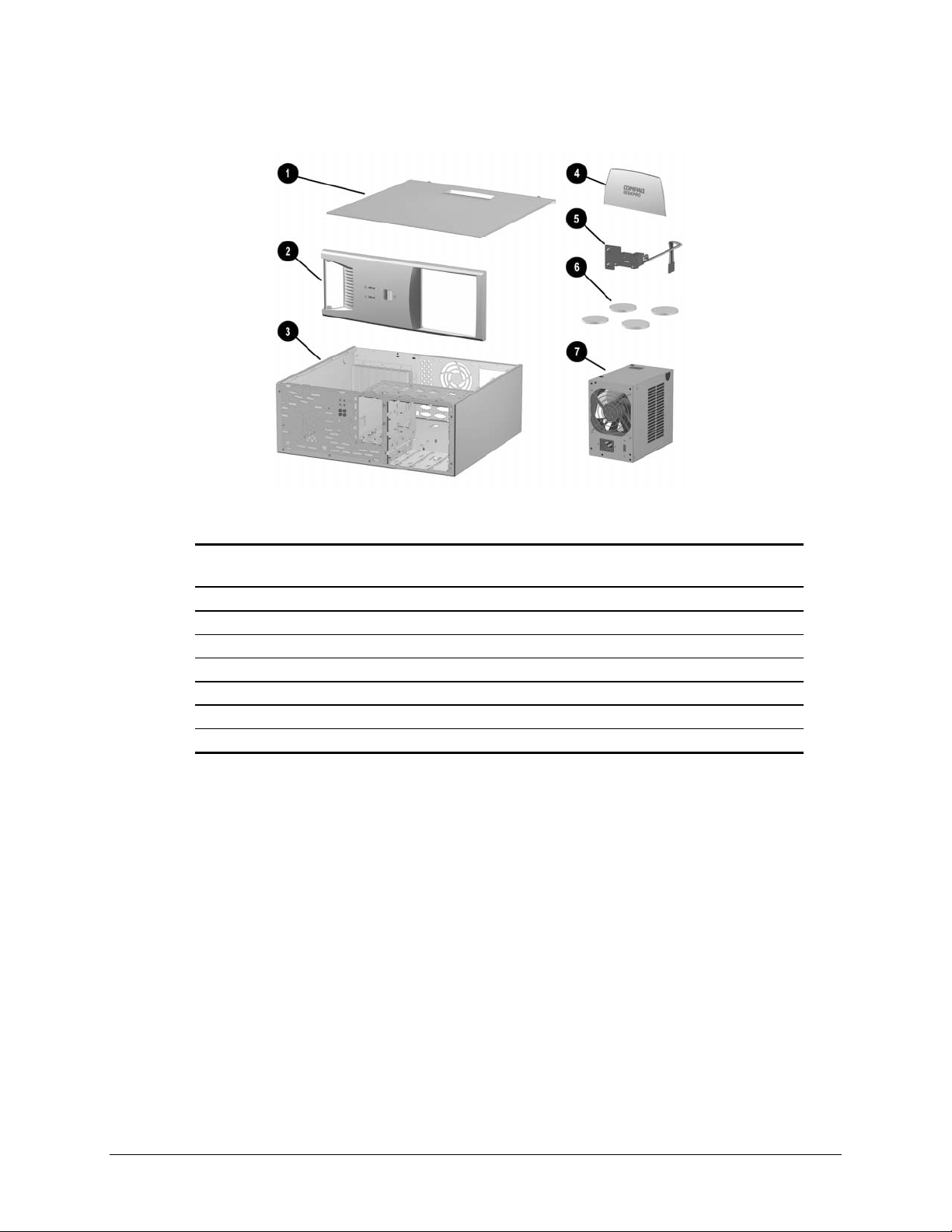
2.1 System Unit
Spare Part
Description
1 Access panel Not spared
2 Front bezel 166868-001 B
3 Chassis/basepan Not spared
4 Logo Kit (only minitower version-166806-002-used) 166924-001 B
5 Power switch with cable, LED and switch holder 199854-001
6 Feet Misc Plastics Kit B
7 Power supply 201828-001 B
Number
Warranty
Tier
2-2 Spare Parts
Page 16
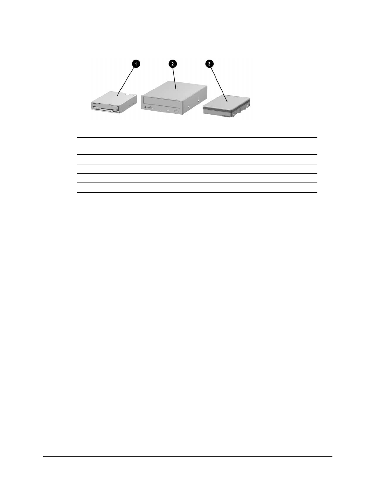
2.2 Mass Storage Devices
Spare Part
Description
1 Diskette drive, 3.5-inch 158266-001 D
2 48X Max tray load IDE CD-ROM drive 187263-001 B
3 10.0-GB Ultra ATA hard drive (66/5400) quiet 203139-001 B
* 15.0-GB Ultra ATA hard drive (66/5400) 202903-001 B
*Not shown
(nn/nnnn) = hard drive transfer rate (MBytes/sec)/RPM
Number
Ultra ATA/100 hard drives are backwards compatible with Ultra ATA/66
devices; however, the data transfer rate is reduced to 66MB/sec.
Warranty
Tier
Compaq Deskpro EX and Deskpro EXS Series of Personal Computers 2-3
Page 17
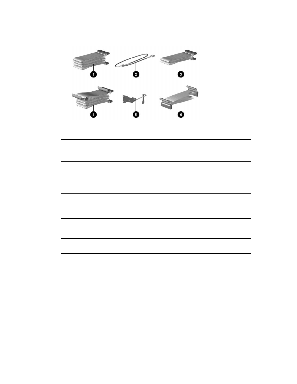
2.3 Cables
Spare Part
Description
Number
Cable Kit includes: 192264-001
1 Single device, hard drive/CD-ROM cable, 18”
(108950-019)
2 Audio cable, 21” (387527-001)
* Single device, hard drive/CD-ROM cable, 12.5”
(105876-001)
* Audio cable, 21”, (288489-002) (not used for this
product)
3 Single device, hard drive/CD-ROM cable, 9.75”
(108950-021)
4 Dual device, hard drive/CD-ROM cable, 18”, 10” to the first
connector
5 Power switch/LED cable 199854-001 B
6 Diskette drive cable 161735-001 B
* CD audio cable 149806-001 D
*Not shown
196667-001 B
Warranty
Tier
B
2-4 Spare Parts
Page 18
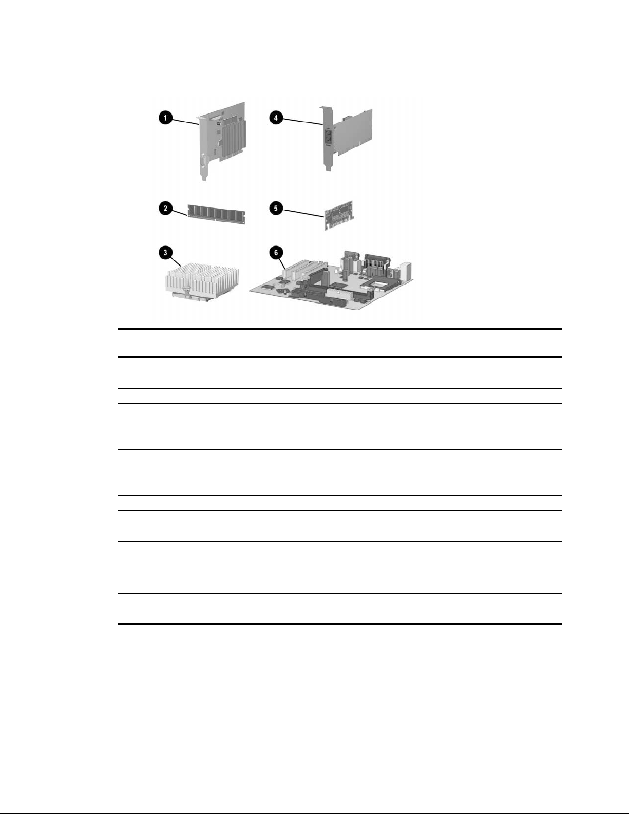
2.4 Standard, Memory, and Expansion Boards
Spare Part
Description
1 Nvidia M64 16MB SDRAM AGP Card 182757-001 B
5 AIMM (GPA) 4MB, 133MHz for graphics 192012-001 B
Memory Module (SDIMM, 133 MHz)
2 128 MB 170081-001 B
256 MB 192014-001 B
Intel Pentium III Processor
3 566/66 MHz with heatsink (191832-002) and clip (223575-007). 203967-001 B
* 600/66 MHz with heatsink (191832-002) and clip (223575-007). 192011-001 B
* 667/133 MHz with heatsink (191832-002) and clip (223575-007). 192007-001 B
* 700/66 MHz with heatsink (191832-002) and clip (223575-007). 203968-001 B
* 733/133 MHz with heatsink (191832-002) and clip (223575-007). 192008-001 B
* 800/133 MHz with heatsink (191832-002) and clip (223575-007). 192009-001 B
* 866/133 MHz with fansink (191845-002). Fansink includes fan,
heatsink, and clip.
* 933/133 MHz with fansink (191845-002). Fansink includes fan,
heatsink, and clip.
4 10/100 PCI Network Interface Card 188297-001 B
6 System Board 203966-001 B
*Not shown.
Number
192006-001 B
203969-001 B
Warranty
Tier
Compaq Deskpro EX and Deskpro EXS Series of Personal Computers 2-5
Page 19
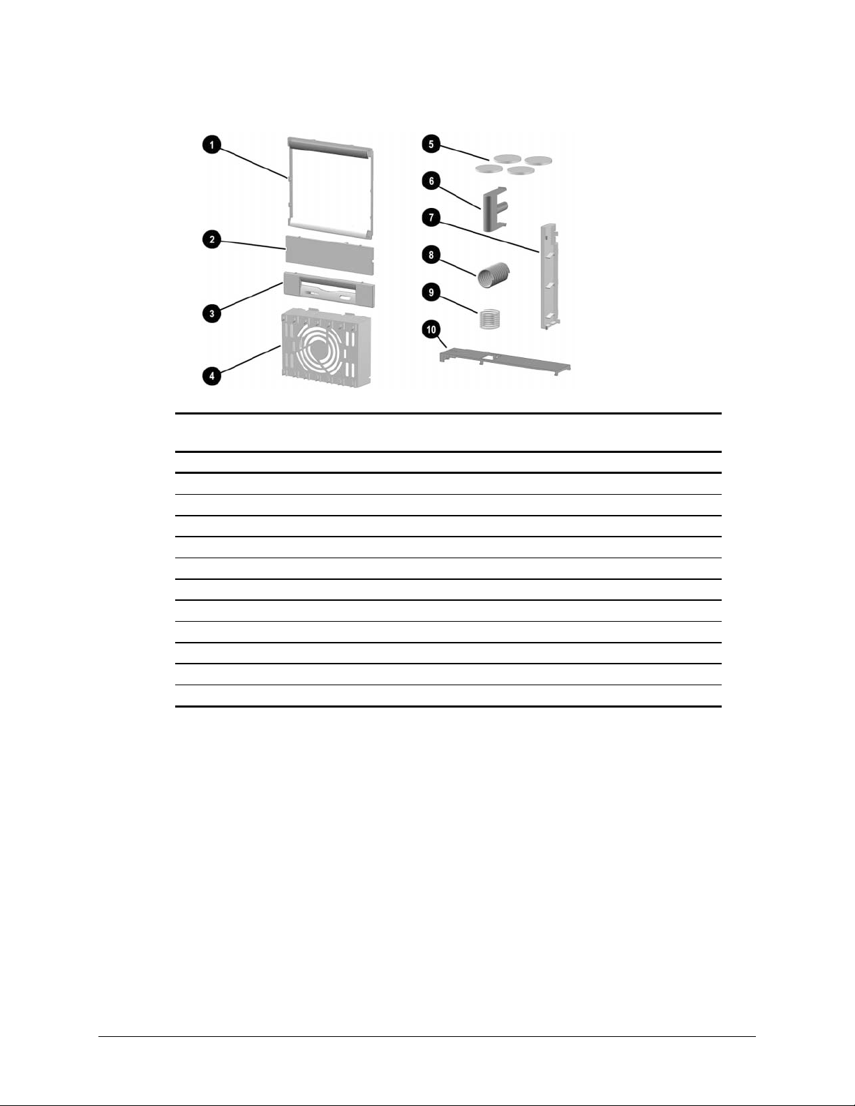
2.5 Miscellaneous Plastics Kit
Spare Part
Description
Number
Miscellaneous Plastics Kit, includes: 166878-001 B
1 Panel, sub (166835-001)
2 Bezel, blank (166775-001)
3 Diskette bezel (166776-001)
4 Card guide (166778-001)
5 Foot, rubber (4 ea.) (166939-002)
6 Button, power (166774-001)
7 Drivelock, DT (166779-001) (not used with this product)
8 Spring, power button (166837-001)
9 Springs, drivelock (2 ea.) (166837-002)
10 Drivelock, MT (166780-001)
* Retention mechanism (2 ea.) (350767-001)
*Not shown
Warranty
Tier
2-6 Spare Parts
Page 20

2.6 Keyboards (not illustrated)
Description
Easy Access Keyboard-US 123130-xxx D
Dutch -331
Finnish -351
French -051
International -B31
Norwegian -091
Spanish -071
Swedish -101
UK -031
US -001
2.7 Miscellaneous Screw Kit (not illustrated)
Description
Miscellaneous Screw Kit, includes : 179180-001 D
6-32 x 1/4 hi-top, thread-forming screw with serrations (5 ea.)
(192308-001)
6-19 x 5/16 panhead, plastite screw (4 ea.) (101346-068)
6-19 x .5/16 hi-top, taptite screw with captive washer (4 ea.)
(114399-069)
6-32 x 3/16 hi-top, thread-forming screw with serrations (5 ea.)
(192308-003)
M3 x 5mm, hi-top, taptite screw with serrations (4 ea.)
(247348-001)
6-32 x 3/16 buttonhead tamper-resistant, taptite screw with
serrations (3 ea.) (296769-002)
6-32 x 5/16 hi-top, taptite screw (4 ea.) (109834-568)
6-19 x 1/2 Panhead, plastite screw (5 ea.) (101346-071)
Thumbscrew, molded cap (4 ea.) (179333-002)
Spare Part
Number
Spare Part
Number
Warranty
Tier
Warranty
Tier
Compaq Deskpro EX and Deskpro EXS Series of Personal Computers 2-7
Page 21

2.8 Miscellaneous Parts (not illustrated)
Description
Mouse – Scroll, Opal 334689-002 D
2.9 Shipping Boxes (not illustrated)
Description Spare Part Number
Return Kit 166990-002
2.10 Documentation and Software (not illustrated)
Description Spare Part Number
Maintenance & Service Guide 215879-001
Illustrated Parts Map 215880-001
Service Reference Guide 152611-001
Quick Troubleshooting Guide 153837-001
Spare Part
Number
Warranty
Tier
2-8 Spare Parts
Page 22

chapter
3
EMOVAL
R
& R
This chapter provides general service information for the computer. Adherence to the
procedures and precautions described in this chapter is essential for proper service.
EPLACEMENT PRELIMINARIES
CAUTION: When the computer is plugged into an AC power source there is always voltage applied
to the system board. You must disconnect the power cord from the power source before opening the
computer to prevent system board or component damage.
3.1 Electrostatic Discharge Information
A sudden discharge of static electricity from your finger or other conductor can destroy
static-sensitive devices or microcircuitry. Often the spark is neither felt nor heard, but
damage occurs. An electronic device exposed to electrostatic discharge (ESD) may not be
affected at all and can work perfectly throughout a normal cycle. The device may function
normally for a while, then degrade in the internal layers, reducin g its life expec tan cy.
Networks built into many integrated circuits provide some protection, but in many cases,
the discharge contains enough power to alter device parameters or melt silicon junctions.
3.1.1 Generating Static
The following table shows that:
Different activities generate different amounts of static electricity.
!
! Static electricity increases as humidity decreases.
Relative Humidity
Event 55% 40% 10%
Walking across carpet 7,500 V 15,000 V 35,000 V
Walking across vinyl floor 3,000 V 5,000 V 12,000 V
Motions of bench worker 400 V 800 V 6,000 V
Removing DIPs* from plastic tube 400 V 700 V 2,000 V
Removing DIPs* from vinyl tray 2,000 V 4,000 V 11,500 V
Removing DIPs* from Styrofoam 3,500 V 5,000 V 14,500 V
Removing bubble pack from PCB 7,000 V 20,000 V 26,500 V
Packing PCBs in foam-lined box 5,000 V 11,000 V 21,000 V
*Dual Inline Packaging (DIP) is the packaging around individual microcircuitry.
These are then multi-packaged inside plastic tubes, trays, or Styrofoam.
700 volts can degrade a product.
✎✎✎✎
Compaq Deskpro EX and Deskpro EXS Series of Personal Computers 3-1
Page 23

3.1.2 Preventing Electrostatic Damage to Equipment
Many electronic components are sensitive to ESD. Circuitry design and structure
determine the degree of sensitivity. The following proper packaging and grounding
precautions are necessary to prevent damage to electric components and accessories.
! To avoid hand contact, transport products in static-safe containers such as tubes,
bags, or boxes.
! Protect all electrostatic parts and assemblies with conductive or approved
containers or packaging.
Keep electrostatic sensitive parts in their containers until they arrive at static-free
!
stations.
! Place items on a grounded surface before removing them from their container.
! Always be properly grounded when touching a sensitive component or assembly.
! Avoid contact with pins, leads, or circuitry.
! Place reusable electrostatic-sensitive parts from assemblies in protective packaging
or conductive foam.
3.1.3 Personal Grounding Methods and Equipment
Use the following equipment to prevent static electricity damage to equipment:
Wrist straps are flexible straps with a minimum of one-megohm +/- 10%
!
resistance in the ground cords. To provide proper ground, a strap must be worn
snug against bare skin. The ground cord must be connected and fit snugly into the
banana plug connector on the grounding mat or workstation.
Heel straps/Toe straps/Boot str a ps can be used at standing workst at ions and are
!
compatible with most types of shoes or boots. On conductive floors or dissipative
floor mats, use them on both feet with a minimum of one-megohm +/- 10%
resistance between the operator and ground.
Static Shielding Protection Levels
Method Voltage
Antistatic plastic 1,500
Carbon-loaded plastic 7,500
Metallized laminate 15,000
3.1.4 Grounding Workstations
To prevent static damage at the workstation, use the following precautions:
! Cover the workstation with approved static-dissipative material. Provide a wrist
strap connected to the work surface and properly grounded tools and equipment.
! Use static-dissipative mats, foot straps, or air ionizers to give added protection.
! Handle electrostatic sensitive components, parts, and assemblies by the case or
PCB laminate. Handle them only at static-free workstations.
! Turn off power and input signals before inserting and removing connectors or test
equipment.
3-2 Removal & Replacement Preliminaries
Page 24

! Use fixtures made of static-safe materials when fixtures must directly contact
dissipative surfaces.
! Keep work area free of nonconductive materials such as ordinary plastic assembly
aids and Styrofoam.
! Use field service tools, such as cutters, screwdrivers, and vacuums, that are
conductive.
3.1.5 Recommended Materials and Equipment
Materials and equipment that are recommended for use in preventing static electricity
include:
Antistatic tape
!
! Antistatic smocks, aprons, or sleeve protectors
! Conductive bins and other assembly or soldering aids
! Conductive foam
! Conductive tabletop workstations with ground cord of one-megohm +/- 10%
resistance
! Static-dissipative table or floor mats with hard tie to ground
! Field service kits
! Static awareness labels
! Wrist straps and footwear straps providing one-megohm +/- 10% resistance
! Material handling packages
Conductive plastic bags
!
! Conductive plastic tubes
! Conductive tote boxes
! Opaque shielding bags
! Transparent metall ized shi eld ing bags
Transparent shielding tubes
!
3.2 Routine Care
3.2.1 General Cleaning Safety Precautions
1. Never use solvents or flammable solutions to clean the computer.
2. Never immerse any parts in water or cleaning solutions; apply any liquids to a clean
cloth and then use the cloth on the component.
3. Always turn off the computer when cleaning with liquids or damp cloths.
4. Always turn off the computer before cleaning the keyboard, mouse, or air vents.
5. Disconnect the keyboard before cleaning it.
6. Wear safety glasses equipped with side shields when cleaning the keyboard.
Compaq Deskpro EX and Deskpro EXS Series of Personal Computers 3-3
Page 25

3.2.2 Cleaning the Computer Case
Follow all safety precautions in Section 3.2.1 before cleaning the computer.
To clean the computer case, follow the procedures described below:
! To remove light stains or dirt, use plain water with a clean, lint-free cloth or swab.
! For stronger stains, use a mild dishwashing liquid diluted with water. Rinse well
by wiping it with a cloth or swab dampened with clear water.
! For stubborn stains, use isopropyl (rubbing) alcohol. No rinsing is needed as the
alcohol will evaporate quickly and not leave a residue.
! After cleaning, always wipe the unit with a clean, lint-free cloth.
! Occasionally clean the air vents on the computer. Lint and other foreign matter can
block the vents and limit the airflow.
3.2.3 Cleaning the Keyboard
Follow all safety precautions in Section 3.2.1 before cleaning the keyboard.
To clean the tops of the keys or the keyboard body, follow the procedures described in
Section 3.2.2.
When cleaning debris from under the keys, review all rules in Section 3.2.1 before
following these procedures:
CAUTION: Use safety glasses equipped with side shields before attempting to clean debris from
under the keys.
! Visible debris underneath or between the keys may be removed by vacuuming or
shaking.
! Canned, pressurized air may be used to clean debris from under the keys. Caution
should be used as too much air pressure can dislodge lubricants applied under the
wide keys.
! If you remove a key, use a specially designed key puller to prevent damage to the
keys. This tool is available through many electronic supply outlets.
CAUTION: Never remove a wide leveled key (like the space bar) from the keyboard. If these keys are
improperly removed or installed, the keyboard may not function properly.
! Cleaning under a key may be done with a swab moistened with isopropyl alcohol
and squeezed out. Be careful not to wipe away lubricants necessary for proper key
functions. Use tweezers to remove any fibers or dirt in confined areas. Allow the
parts to air dry before reassembly.
3.2.4 Cleaning the Monitor
! Wipe the monitor screen with a clean cloth moistened with water or with a
towelette designed for cleaning monitors. Do not use sprays or aerosols directly on
the screen, the liquid may seep into the housing and damage a component. Never
use solvents or flammable liq uid s on the monito r.
! To clean the monitor body follow the procedures in Section 3.2.2.
3-4 Removal & Replacement Preliminaries
Page 26

3.2.5 Cleaning the Mouse
Before cleaning the mouse, ensure that the power to the com puter is turn ed o ff.
! Clean the mouse ball by first removing the retaining plate and the ball from the
housing. Pull out any debris from the ball socket and wipe the ball with a clean dry
cloth before reassembly.
! To clean the mouse body, follow the procedures in 3.2.2.
3.3 Service Considerations
Listed below are some of the considerations that you should keep in mind during the
disassembly and assembly of the computer.
3.3.1 Power Supply Fan
The power supply fan is a variable-speed fan based on the temperature in the power
supply.
CAUTION: The cooling fan is off only when the computer is turned off or the power cable has been
disconnected.
The cooling fan is always on in all other instances (when the computer is either in the “On,” “Standby,”
or “Suspend” mode).
You must disconnect the power cord from the power source before opening the computer to prevent
system board or component damage.
3.3.2 Tools and Software Requirements
To service the computer, you need the following:
! Torx T-15 screwdriver (Compaq screwdriver with bits PN 161946-001)
! Flat-bladed screwdriver (may sometimes be used in place of the Torx screwdriver)
! Diagnostics software
! Compaq tamper-resistant T-15 wrench (Smart Cover FailSafe Key, PN 166527-
001) or Compaq tamper-resistant bits (Smart Cover FailSafe Key, PN 166527-002)
3.3.3 Screws
The screws used in the computer are not interchangeable. They may have standard or
metric threads and may be of different lengths. If an incorrect screw is used during the
reassembly process, it can damage the unit. Compaq strongly recommends that all screws
removed during disassembly be kept with the part that was removed, then returned to their
proper locations.
✎
As each subassembly is removed from the computer, it should be placed away
from the work area to prevent damage.
Compaq Deskpro EX and Deskpro EXS Series of Personal Computers 3-5
Page 27

3.3.4 Cables and Connectors
Most cables used throughout the unit are flat, flexible cables. These cables must be
handled with care to avoid damage. Apply only the tension required to seat or unseat the
cables during insertion or removal from the connector. Handle cables by the connector
whenever possible. In all cases, avoid bending or twisting the cables, and ensure that the
cables are routed in such a way that they cannot be caught or snagged by parts being
removed or replaced.
CAUTION: When servicing this computer, ensure that cables are placed in their proper location during
the reassembly process. Improper cable placement can damage the computer.
3.3.5 Hard Drives
Handle hard drives as delicate precision components, avoiding all physical shock and
vibration. This applies to failed drives as well as replacement spares.
! If a drive must be mailed, place the drive in a bubble-pack mailer or other suitable
protective packaging and label the package “Fragile: Handle With Care.”
! Do not remove hard drives from the shipping package for storage. Keep hard
drives in their protective packaging until they are actually mounted in the CPU.
! Avoid dropping drives from any height onto any surface.
! If you are inserting or removing a hard drive, turn off the computer. Do not remove
a hard drive while the computer is on or in standby mode.
! Before handling a drive, ensure that you are discharged of static electricity. While
handling a drive, avoid touching the connector. For more information about
preventing electrostatic damage, refer to Section 3.1, “Electrostatic Discharge.”
! Do not use excessive force when inserting a drive.
! Avoid exposing a hard drive to liquids, temperature extremes, or products that
have magnetic fields such as monitors or speak ers.
3.3.6 Lithium Coin Cell Battery
The battery that comes with the computer provides power to the real-time clock and has a
minimum lifetime of about three years.
See Chapter 4, “Removal and Replacement Procedures,” for instructions on the
replacement procedures.
WARNING: This computer contains a lithium battery. There is a risk of fire and chemical burn if the
!
battery is handled improperly. Do not disassemble, crush, puncture, short external contacts, dispose in
water or fire, or expose it to temperatures higher than 140ºF (60ºC).
CAUTION: Batteries, battery packs, and accumulators should not be disposed of together with the
general household waste.
3-6 Removal & Replacement Preliminaries
Page 28

chapter
4
EMOVAL AND REPLACEMENT PROCEDURES
R
This chapter provides general service information for the computer. Adherence to the
procedures and precautions described in this chapter is essential for proper service.
After completing all necessary removal and replacement procedures, run the Diagnostics
utility to verify that all components operate properly.
4.1 Disassembly Sequence Chart
Use the chart below to determine the disassembly sequence for removing components
from the computer.
4.3 Feet Installation
4.4 Cable Lock
4.5 Access Panel
4.6 Front Bezel
4.7 Power Button
4.8 Subpanel and Bezel Blanks
4.9 Power Switch Assembly
4.10.1 Removing an Internal 3.5-Inch Hard Drive
4.10.2 Removing an External 5.25-Inch Drive
4.10.3 Removing an External 3.5-Inch Drive
4.11 Expansion Boards
4.12 System Memory
4.13 Graphics Cards
4.14 Processor
4.15 System Board
4.16 Lithium Battery
4.17 Chassis Fan Assembly
4.18 Power Supply
Compaq Deskpro EX and Deskpro EXS Series of Personal Computers 4-1
Page 29

4.2 Disassembly Preparation
Before adding any internal options or performing a removal/replacement:
1. Remove any diskette, compact disc, or tape from the computer.
2.
Turn off the computer and any peripheral devices that are connected to it.
WARNING: Power is continuous to the system board and power supply even when the power
switch is turned off. To prevent damage to the unit, disconnect the power cord from the power
source or the unit before beginning disassembly procedures.
CAUTION: Turn off the computer before disconnecting any cables.
3. Disconnect the power cord from the electrical outlet and then from the computer.
4. Disconnect all peripheral device cab les from the com put er.
✎
During disassembly, label each cable as you remove it, noting it s posi tion and
routing. Keep all screws with the components removed.
CAUTION: The screws used in the computer are of different thread sizes and lengths; using the
wrong screw in an application may damage the unit.
WARNING: To reduce the risk of personal injury from hot surfaces, allow the internal system
components to cool before touching.
CAUTION: Static electricity can damage the electronic components of the computer or optional
equipment. Before beginning these procedures, ensure that you are discharged of static electricity
by briefly touching a grounded metal object. For more information, refer to Chapter 3, “Removal
and Replacement Preliminaries.”
4-2 Removal & Replacement Procedures
Page 30

4.3 Feet Installation
Four (4) rubber feet are mounted to the chassis, as shown below. No parts have to be
removed to access the feet. The replacement feet have an adhesive surface and are shipped
with a protective backing in place. Remove the backing from the feet before installation.
If necessary, remove the old feet and remove any adhesive residue from the chassis.
Compaq Deskpro EX and Deskpro EXS Series of Personal Computers 4-3
Page 31

4.4 Cable Lock
WARNING:
bracket; metal edges may be sharp. Be sure to install the bracket so that sharp edges do
not extend from the edges of the computer chassis.
Depending on the model, the computer includes a cable lock provision, which consists of
a three-piece security bracket. The bottom part of the bracket is attached to the computer
with a screw; the top part of the bracket covers the screw and prevents its removal.
1.
Separate the pieces of the security bracket by bending the metal where the three pieces
join.
2. Slide the tab on the narrow piece of the bracket into the notch on the back of the
computer and rotate this piece toward the screw hole, then slide the U-shaped piece of
the bracket between the narrow piece and the computer.
3. Position both pieces of the bracket over the screw hole and secure the bracket to the
computer with the screw provided.
4. Cover the screw with the flat portion of the security b racke t.
5. Install a padlock (not provided) to secure the top part of the security bracket and inhibit
access to the inside of the computer. Install a cable lock (not provided) to inhibit access
to the interior of the computer and secure the computer to a fixed object.
To avoid injury, use care in handling the separated pieces of the cable lock
To remove the cable lock provision, reverse the above procedure.
4-4 Removal & Replacement Procedures
Page 32

4.5 Access Panel
1. Prepare the computer for disassembly (Section 4.2).
WARNING: Power is continuous to the system board and power supply even when the power
switch is turned off. To prevent damage to the unit, disconnect the power cord from the power
source or the unit before beginning disassembly procedures.
2.
Lay the computer down on its large base for greater stability.
3. Loosen the two thumbscrews that secure the access panel to the back of the computer
chassis.
4. Slide the access panel backward approximately 1-inch (2.5-cm); then lift it up and off
the unit.
To replace the access panel, reverse the previous steps.
Compaq Deskpro EX and Deskpro EXS Series of Personal Computers 4-5
Page 33

4.6 Front Bezel
1. Prepare the computer for disassembly (Section 4.2).
WARNING: Power is continuous to the system board and power supply even when the power
switch is turned off. To prevent damage to the unit, disconnect the power cord from the power
source or the unit before beginning disassembly procedures.
2.
Remove the access panel (Section 4.5).
3. Press the release tabs 1 on the side of the front bezel.
4. Rotate the front bezel away from the chassis to remove it from the unit 2.
✎
4-6 Removal & Replacement Procedures
When replacing the front bezel, ensure that the bottom hinge points are properly
placed in the chassis before rotating the front bezel back into its original position.
Page 34

4.7 Power Button
1. Prepare the computer for disassembly (Section 4.2).
WARNING: Power is continuous to the system board and power supply even when the power
switch is turned off. To prevent damage to the unit, disconnect the power cord from the power
source or the unit before beginning disassembly procedures.
2.
Lay the computer down on its large base for greater stability.
3. Remove the access panel (Section 4.5).
4. Remove the front bezel (Section 4.6).
5. Pinch the two tabs of the power button together and pull the button out of the front
bezel. The spring will follow the button out of the housing.
To replace the power button, reverse the above procedure.
Compaq Deskpro EX and Deskpro EXS Series of Personal Computers 4-7
Page 35

4.8 Subpanel and Bezel Blanks
The subpanel and bezel blanks must be removed from the front bezel if you are installing
a mass storage device for the first time.
WARNING: Power is continuous to the system board and power supply even when the power
switch is turned off. To prevent damage to the unit, disconnect the power cord from the power
source or the unit before beginning disassembly procedures.
1. Prepare the computer for disassembly (Section 4.2).
2. Lay the computer down on its large base for greater stability.
3. Remove the access panel (Section 4.5).
4. Remove the front bezel (Section 4.6).
5.
Pull on the subpanel to remove it from the inside of the front bezel.
CAUTION: Hold the subpanel straight when you pull it away from the front bezel. Pulling at an
angle could damage the pins that align the subpanel within the front bezel.
6. Gently push on the bezel blanks to remove them from the subpanel.
CAUTION: When replacing the subpanel, ensure that the aligning pins and any remaining bezel
blanks are in the proper orientation to prevent damage to the alignment pins.
✎
4-8 Removal & Replacement Procedures
The subpanel has markings on it to facilitate installation.
Page 36

4.9 Power Switch Assembly
CAUTION: The power switch should not be removed from the switch holder. Doing so may
damage the switch components.
1. Prepare the computer for disassembly (Section 4.2).
WARNING: Power is continuous to the system board and power supply even when the power
switch is turned off. To prevent damage to the unit, disconnect the power cord from the power
source or the unit before beginning disassembly procedures.
2. Lay the computer down on its large base for greater stability.
3. Remove the access panel (Section 4.5).
4. Remove the front bezel (Section 4.6).
5. Disconnect the power/LED cable from the system board 1.
6. Push the release tab 2 toward the drive bays, then remove the power switch assembly
from the chassis.
To install the new power switch, reverse the above procedure, pushing the switch
assembly until it snaps into place. The power/LED connector is keyed to ensure proper
installation.
Compaq Deskpro EX and Deskpro EXS Series of Personal Computers 4-9
Page 37

4.10 Mass Storage Devices
The Compaq Deskpro EX Series of Personal Computers support up to five drives in
various configurations.
Drive Positions
Reference Drive Bay Configuration
12
3
45
✎
To verify the type and size of the mass storage devices installed in the computer, run
Computer Setup.
1, 2 Two standard 5.25-inch, half-height bays for optional drives.
3
4, 5
One standard 3.5-inch, 1.44-MB diskette drive mounted with a drive
adapter into a 5.25-inch bay.
Two standard 3.5-inch drive bays; bay 4 contains the preinstalled
hard drive, bay 5 is available for an optional hard drive.
Drive bay numbers are stamped on the chassis.
4-10 Removal & Replacement Procedures
Page 38

When installing additional drives, fo llow the se gu ide line s :
! For optimal performance, connect hard drives to the primary controller. Connect
expansion devices, such as CD-ROM, IDE tape, and diskette drives to the
secondary controller.
! You may install either a third-height or a half-height drive into a half-height bay.
You must install guide screws to ensure that the drive lines up correctly in the
!
drive cage. Compaq has provided extra guide screws, which are installed in the
front of the computer chassis, behind the front bezel. Some options require metric
hardware. Compaq-supplied metric screws are black.
WARNING: Power is continuous to the system board and power supply even when the power
switch is turned off. To prevent damage to the unit, disconnect the power cord from the power
source or the unit before beginning disassembly procedures.
Using the Cable-Select Feature with Ultra ATA Devices
Optional drives are available from Compaq in kits that include a special drive cable. The
configuration of the drives employs a cable-select feature that identifies the drives as
device 0 (primary drive) or device 1 (secondary drive). The system board determines
which drive is device 0 or device 1, based on the way the drives are connected to the
special drive cable. The device 0 drive is the drive connected to the short segment of the
drive cable (or that connector closest to the system board); the device 1 drive is the drive
connected to the long segment of the drive cable.
Drive installation requires no jumper setting changes on the existing or optional drives.
All Compaq drives have the jumpers preset for cable-select installation.
✎
If installing a second device on the primary controller, you must use an
80-conductor Ultra ATA cable for optimal performance. This cable is
available as a Compaq option.
Compaq Deskpro EX and Deskpro EXS Series of Personal Computers 4-11
Page 39

4.10.1 Removing an Internal 3.5-Inch Hard Drive
1. Prepare the computer for disassembly (Section 4.2).
2.
Remove the access panel (Section 4.5).
3. Remove the front bezel (Section 4.6).
4. Disconnect the power and data cables from the back of the hard drive.
5. Slide the drivelock mechanism to unlock the hard drives 1.
6. While holding the drivelock in the unlocked position, remove the drive from the drive
bay 2.
7.
Remove the guide screws from the drive.
8. Install two guide screws on each side of the replacement drive (use silver screws).
✎
Replace the 3.5-inch drive by reversing the above procedure.
✎
The system automatically recognizes hard drives sold by Compaq (or any other plug and
play hard drive) and will automatically reconfigure the computer. If you installed a thirdparty hard drive, or one that is not a plug and play device, you must run Computer Setup
to reconfigure the computer.
Metric screws (M3) have a black finish while U.S. screws (#6) have a silver
finish.
CAUTION: When servicing the computer, ensure that cables are placed in their proper locations
during the reassembly process. Improper cable placement can damage the computer.
CAUTION: Use only 3/16-inch or 5-mm long screws as guide screws. Longer screws can damage
the internal components of the drive.
When installing a second ATA hard drive on the primary controller, you must use
an 80-conductor ATA cable for optimal performance.
4-12 Removal & Replacement Procedures
Page 40

4.10.2 Removing an External 5.25-Inch Drive
1. Prepare the computer for disassembly (Section 4.2).
WARNING: Power is continuous to the system board and power supply even when the power
switch is turned off. To prevent damage to the unit, disconnect the power cord from the power
source or the unit before beginning disassembly procedures.
2. Remove the access panel (Section 4.5).
3. Remove the front bezel (Section 4.6).
4.
Slide the drivelock mechanism to unlock the drive 1.
5. While the drivelock is held in the unlatched position, remove the drive from the drive
bay 2.
6. Remove the guide screws from the drive.
To install a new drive:
1. Install two guide screws on each side of the replacement drive.
✎
2.
Ensure that the guide screw lines up with the guide slots, then gently slide the drive into
the drive bay until it snaps into place.
3.
Connect the power and signal cables to the back of the drive.
4.
Remove the bezel blank from the subpanel, if necessary (Section 4.8).
5.
Reinstall the subpanel and the front bezel.
The system automatically recognizes hard drives sold by Compaq (or any other plug and
play hard drive) and will automatically reconfigure the computer. If you installed a thirdparty hard drive, or one that is not a plug and play device, you must run Computer Setup
to reconfigure the computer.
Metric screws (M3) have a black finish while U.S. screws (#6) have a silver
finish. CD and DVD drives use black metric screws.
Compaq Deskpro EX and Deskpro EXS Series of Personal Computers 4-13
Page 41

4.10.3 Removing an External 3.5-Inch Drive
If you are installing a second 3.5-inch diskette drive into 5.25-inch bays #1 or 2 for the
first time, you must use a special adapter bracket.
If you are installing a 3.5-inch diskette drive into 5.25-inch bay #3, you must use a special
adapter bracket.
If installing a second ATA hard drive on the primary controller, you must use an 80conductor ATA cable for optimal performance.
1. Prepare the computer for disassembly (Section 4.2).
WARNING: Power is continuous to the system board and power supply even when the power
switch is turned off. To prevent damage to the unit, disconnect the power cord from the power
source or the unit before beginning disassembly procedures.
2. Remove the access panel (Section 4.5).
3. Remove the front bezel (Section 4.6).
✎
4. Slide the drivelock mechanism to unlock the drive 1.
The primary diskette drive is always installed in drive bay 3.
5.
While the drivelock is held in the unlatched position, remove the drive from the drive
bay 2.
4-14 Removal & Replacement Procedures
Page 42

6. Remove the bracket brace 1 from the top of the drive adap te r by squeezin g inward
on both sides, then rotating the brace up and out.
7.
Remove the drive bezel 2.
8. Remove the three screws 3 that secure the drive 4 to the drive adapter.
9. Lift the drive out of the drive adapter.
10. Remove the guide screws from the drive 5.
To replace the drive, reverse the previous procedures.
✎
The primary 3.5-inch diskette drive should only be installed into bay 3. Bay 3 is
the bottom bay in the minitower.
When replacing the drive, use the existing screws.
Metric screws (M3) have a black finish while U.S. screws (#6) have a silver
finish.
Diskette drives use black metric screws. The drive adapters use silver U.S.
screws.
CAUTION: When servicing the computer, ensure that cables are placed in their proper locations
during the reassembly process. Improper cable placement can damage the computer.
CAUTION: Use only 3/16-inch or 5-mm long screws as guide screws. Longer screws can damage
the internal components of the drive.
Compaq Deskpro EX and Deskpro EXS Series of Personal Computers 4-15
Page 43

4.11 Expansion Boards
4.11.1 Expansion Board Slots
1
PCI expansion slots
2
AGP graphics slot
4-16 Removal & Replacement Procedures
Page 44

4.11.2 Removing a PCI Expansion Board
1. Prepare the computer for disassembly (Section 4.2).
WARNING: Power is continuous to the system board and power supply even when the power
switch is turned off. To prevent damage to the unit, disconnect the power cord from the power
source or the unit before beginning disassembly procedures.
2. Lay the computer down on its large base for greater stability.
3. Remove the access panel (Section 4.5).
4. Disconnect any cables from the expansion board, noting their location for reinstallation.
5.
Remove the expansion board retaining screw.
6. Hold the board at each end and carefully rock it back and forth while pulling upward
until the connectors pull free from the slot. Be sure not to scrape the card against other
components
7. If not installing another expansion board in the slot, then close off the open slot by
installing an expansion slot cover with a screw.
Compaq Deskpro EX and Deskpro EXS Series of Personal Computers 4-17
Page 45

4.11.3 Installing a PCI Expansion Board
1. Prepare the computer for disassembly (Section 4.2).
WARNING: Power is continuous to the system board and power supply even when the power
switch is turned off. To prevent damage to the unit, disconnect the power cord from the power
source or the unit before beginning disassembly procedures.
2. Lay the computer down on its large base for greater stability.
3. Remove the access panel (Section 4.5).
4. If you are installing an expansion board for the first time, remove the expansion slot
cover.
4-18 Removal & Replacement Procedures
Page 46

5. Hold the board at each end and carefully rock it back and forth while pushing
downward, until the connectors fit complet ely and fi rmly into the expansion slot.
6. Secure the board to the chassis with the retaining screw.
7. Attach any cables that came with the board.
✎
8.
Reassemble the computer.
The computer should automatically recognize the added plug and play board.
If installing a NIC board, attach the WOL power cable to connector P9 on the
system board, if applicable.
Compaq Deskpro EX and Deskpro EXS Series of Personal Computers 4-19
Page 47

4.12 System Memory
The computer comes with synchronous dynamic random access memory (SDRAM) dual
inline memory modules (DIMMs). The Intel 815 chipset comes with at least 64 MB of
SDRAM DIMMS, upgradeable to 512 MB.
DIMMs
The memory sockets on the Intel 815 chipset–based system board can be populated with
industry-standard DIMMs. These memory module slots are populated with at least one
preinstalled memory module. To achieve the ma xi mu m mem ory suppo rt, you may be
required to replace the preinstalled DIMM with a higher capacity DIMM.
For proper system operation, the DIMMs must be industry-standard 168-pin, unbuffered
PC100– or PC133– compliant SDRAM DIMMs, depending on the model. The SDRAM
DIMMs must support CAS Latency 2 or 3 (CL = 2 or CL = 3). They must also contain the
mandatory Joint Electronic Device Engineering Council (JEDEC) Serial Presence Detect
(SPD) information. DIMMs constructed with x4 SDRAM (16 ICs per side) are not
supported; the system will not start using unsupported DIMMs.
The Intel 815 chipset supports both PC100 and PC133 SDRAM DIMMs. PC133 DIMMs
should be used for optimal performance. If both PC100 and PC133 SDRAM DIMMs are
installed in a computer, the system memory will run at the lower 100Mhz speed. Some
configurations of PC133 SDRAMs may run at 100Mhz, instead of 133Mhz.
Memory Module Installation
CAUTION:
it is important to use memory modules with gold metal contacts to prevent corrosion and/or
oxidation resulting from having incompatible metals in contact with each other.
CAUTION:
cards. Before beginning these procedures, ensure that you are discharged of static electricity by
briefly touching a grounded metal object. Refer to Appendix F, “Electrostatic Discharge,” for more
information.
CAUTION:
may damage the module.
Your memory module sockets have gold metal contacts. When upgrading your memory,
Static electricity can damage the electronic components of the computer or optional
When handling a memory module, be careful not to touch any of the contacts. Doing so
4-20 Removal & Replacement Procedures
Page 48

To install a memory module, complete the fol low ing step s:
1. Prepare the computer for disassembly (Section 4.2).
WARNING: Power is continuous to the system board and power supply even when the power
switch is turned off. To prevent damage to the unit, disconnect the power cord from the power
source or the unit before beginning disassembly procedures.
2. Remove the access panel (Section 4.5).
3.
Open both latches of the memory socket ", and inser t the me mory mod u le in to the
socket #.
4. A memory module can be installed in only one way. Match the notch on the module
with the tab on the memory socket. Push the module down into the socket, ensuring the
module is securely seated. Close both latches $.
5. Repeat step 4 for any additional modules you want to install.
6. Reassemble the computer.
7. Turn on the computer.
✎
When a memory module has been removed, moved, or added, Memory Change
Alerts, a feature of Intelligent Manageability, alerts the system administrator and
end user. The system automatically recognizes the added memory.
Compaq Deskpro EX and Deskpro EXS Series of Personal Computers 4-21
Page 49

4.13 Graphics Cards
The AGP expansion slot may come with a retention mechanism installed around it to hold
the graphics cards securely in place. There are two different types of retention
mechanisms that may be installed around the AGP expansion slot.
4.13.1 Graphics Performance Accelerator (GPA)/AGP Inline Memory
Module (AIMM) Card with a Type I Retention Mechanism
Removing a GPA/AIMM Card
1.
Prepare the computer for disassembly (Section 4.2).
WARNING: Power is continuous to the system board and power supply even when the power
switch is turned off. To prevent damage to the unit, disconnect the power cord from the power
source or the unit before beginning disassembly procedures.
2. Lay the computer down on its large base for greater stability.
3. Remove the access panel (Section 4.5).
4. Pull the arm on the right side of the retention mecha nism 1.
5. At the same time, rotate the front of the GPA/AIMM card up until it is at a 45 degree
angle 2.
6.
Remove the card from the expansion slot 3.
4-22 Removal & Replacement Procedures
Page 50

Installing a GPA/AIMM Card
WARNING: Power is continuous to the system board and power supply even when the power
switch is turned off. To prevent damage to the unit, disconnect the power cord from the power
source or the unit before beginning disassembly procedures.
1. Prepare the computer for disassembly (Section 4.2).
2. Lay the computer down on its large base for greater stability.
3. Remove the access panel (Section 4.5).
4. Insert the hook 1 on the left side of the GPA/AIMM card under the loop 2 on the left
side of the retention mechanism.
5. Rotate the right side of the card down until it is at a 45 degree angle 3.
Compaq Deskpro EX and Deskpro EXS Series of Personal Computers 4-23
Page 51

6. With the GPA/AIMM card at a 45 degree angle, slide the card toward the back of the
expansion slot 4 until the fingers on the bottom of the card line up properly with the
connectors in the expansion slot.
CAUTION:
expansion slot during installation. Misalignment may result in damage to the card or the AGP
connector.
7.
While pulling the arm on the right side of the retentio n mecha nis m 5, rota te the card
The fingers on the bottom of the GPA/AIMM card must be properly aligned with the
down into the expansion slot until seated 6.
4-24 Removal & Replacement Procedures
Page 52

4.13.2 AGP Card with a Type I Retention Mechanism
Removing an AGP Card
1. Prepare the computer for disassembly (Section 4.2).
2. Lay the computer down on its large base for greater stability.
3. Remove the access panel (Section 4.5).
4. Remove the screw at the top of the expansion slot.
5.
Pull the arm on the right side of the retention mecha nism .
6. Pull the card straight up to remove it from the expansion slot.
To install the graphics card, reverse the above procedures.
Compaq Deskpro EX and Deskpro EXS Series of Personal Computers 4-25
Page 53

4.13.3 GPA/AIMM Card with a Type 2 Retention Mechanism
Removing a GPA/AIMM Card
1. Prepare the computer for disassembly (Section 4.2).
2. Lay the computer down on its large base for greater stability.
3. Remove the access panel (Section 4.5).
4. Pull the arm on the right side of the retention mecha nism .
5.
Pull the card straight up to remove it from the expansion slot.
To install the graphics card, reverse the above procedures.
4-26 Removal & Replacement Procedures
Page 54

4.13.4 AGP Card with a Type 2 Retention Mechanism
Removing an AGP Card
1. Prepare the computer for disassembly (Section 4.2).
2. Lay the computer down on its large base for greater stability.
3. Remove the access panel (Section 4.5).
4. Remove the screw at the top of the expansion slot.
5.
Pull the arm on the right side of the retention mecha nism .
6. Pull the card straight up to remove it from the expansion slot.
To install the graphics card, reverse the above procedures.
Compaq Deskpro EX and Deskpro EXS Series of Personal Computers 4-27
Page 55

4.13.5 Standard AGP Expansion Card
Removing an AGP Card
1. Prepare the computer for disassembly (Section 4.2).
2. Lay the computer down on its large base for greater stability.
3. Remove the access panel (Section 4.5).
4. Remove the screw at the top of the expansion slot.
5.
Remove the AGP graphics board as you would any PCI expansion board
(Section 4.11.2).
4-28 Removal & Replacement Procedures
Page 56

4.14 Processor
1. Prepare the computer for disassembly (Section 4.2).
WARNING: Power is continuous to the system board and power supply even when the power
switch is turned off. To prevent damage to the unit, disconnect the power cord from the power
source or the unit before beginning disassembly procedures.
2.
Remove the computer cover (Section 4.3).
3. If there is a fansink on the processor, unplug the fan cable from the system board.
4. Remove the heatsink retaining clip 1 by pressing down on the clip’s extended tab until
it releases from the safety catch.
5. Lift the heatsink 2 off the processor.
6. Release the processor 3 from the socket by pulling the handle on the ZIF socket out
and upward 4.
7. Lift the processor out of the socket.
WARNING: Removing the heatsink from the processor destroys the integrity of the thermal
interface pad between the two. Whenever the heatsink is removed, the thermal interface pad
must to be removed and a new one installed in its place.
Compaq Deskpro EX and Deskpro EXS Series of Personal Computers 4-29
Page 57

Before installing a fansink, prepare for its installation by doing one of the following:
• New heatsink : if the heat sink ha s a therma l int erf ace attac h ed to its bottom , peel off the
protective paper before installing the heatsink, if necessary.
• Reinstalled heatsink: Note where the thermal interface is located on the heatsink. Carefully
remove the thermal interface pad and all residue from the heatsink surface. If any thermal
interface remains on the die of the processor, scrape it off with your fingernail. A Q-Tip
dipped in alcohol can be used to clean both surfaces. Add thermal interface pad to the
bottom of the heatsink before reinstalling the original heatsink to insure an efficient thermal
interface. Use Compaq part number 210397-001 thermal interface pad.
CAUTION: Thermal interface heat transmission is reduced if residue remains on the heatsink or
processor, or the heatsink thermal interface surface is scratched. This could lead to the processor
running at a higher than normal temperature, fan turning at a higher than normal speed, and
possible loss of data if processor shuts down from overheating.
✎
✎
✎
Ensure that the pins on the processor are properly aligned before inserting the
processor in the ZIF socket. Two corners of the processor will not have an
outermost pin.
All units with 866 MHz and faster processors require an active fansink. When
installing the fan, make sure it is positioned so it blows down on the processor.
All units with 866 MHz and faster processors require use of a chassis fan
(Section 4.15).
4-30 Removal & Replacement Procedures
Page 58

4.15 System Board
✎
1.
Prepare the computer for disassembly (Section 4.2).
2. Remove the access panel (Section 4.5).
3.
Remove all expansion boards (Section 4.11).
4.
Disconnect any cables that are attached to the system board, noting their location for
reinstallation.
5. Remove the DIMMs (optional) (Section 4.12).
6.
Remove the graphics card (Section 4.13).
7. Remove the six retaining screws that secure the system board to the chassis.
8. Slide the board about ½ inch toward the front of the chassis to disengage the I/O panel,
then lift it up and out of the chassis.
More information on the system board, including troubleshooting criteria, can be
found in the Compaq Quick Troubleshooting Guide (part number 153837-001)
and the Compaq Service Reference Guide (part number 152611-001).
WARNING: Power is continuous to the system board and power supply even when the power
switch is turned off. To prevent damage to the unit, disconnect the power cord from the power
source or the unit before beginning disassembly procedures.
To install a new system board, reverse the above procedures.
Compaq Deskpro EX and Deskpro EXS Series of Personal Computers 4-31
Page 59

4.16 Battery
1. Prepare the computer for disassembly (Section 4.2).
2. Lay the computer down on its large base for greater stability.
3.
Remove the access panel (Section 4.5).
4.
Locate the battery on the system board. If you have expansion boards installed, you
may need to remove them to gain access to the battery (Section 4.11.2).
5. Lift the battery out of the holder.
6. Slide the replacement battery into position with the positive side up. The battery holder
automatically secures the battery in the proper position.
7. If you removed expansion boards, reinstall them now.
8.
Replace the computer access panel.
9. Reassemble the computer.
10. Reconnect the AC power cord and turn on the computer.
11. Reset the date and time, your passwords, and any special system setups, using Compaq
Computer Setup.
WARNING: This computer contains a lithium battery. There is a risk of fire and chemical burn if
the battery pack is handled improperly. Do not disassemble, crush, puncture, short external
contacts, dispose in water or fire, or expose it to temperatures higher than 60ºC (140ºF).
In North America, dispose of nickel metal hydride or lithium batteries by taking advantage of the
Compaq battery recycling program. You will be provided with a postage-paid battery pack mailer
preaddressed to a reclamation facility where the metals are recycled. Call the telephone number
listed for your location in the Contacting Customer Support guide for more information.
In Europe, do not dispose of batteries with general household waste. Dispose of or recycle them by
using the public collection system or returning them to Compaq, your authorized Compaq partners,
or their agents.
4-32 Removal & Replacement Procedures
Page 60

4.17 Chassis Fan Assembly
✎
1. Prepare the computer for disassembly (Section 4.2).
2. Remove the access panel (Section 4.5).
3. Disconnect the fan power cable 1 from the system board.
4. Remove the four screws 2 that secure the fan to the chassis.
5. Remove the fan from the chassis 3.
If the unit has a 866 - 933MHz processor, it requires an external chassis fan.
WARNING: Power is continuous to the system board and power supply even when the power
switch is turned off. To prevent damage to the unit, disconnect the power cord from the power
source or the unit before beginning disassembly procedures.
To install the fan assembly, reverse the above proced ure.
✎
This fan is used in units with 866-933 MHz processors.
Compaq Deskpro EX and Deskpro EXS Series of Personal Computers 4-33
Page 61

4.18 Power Supply
1. Prepare the computer for disassembly (Section 4.2).
WARNING: Power is continuous to the system board and power supply even when the power
switch is turned off. To prevent damage to the unit, disconnect the power cord from the power
source or the unit before beginning disassembly procedures.
2.
Lay the computer down on its large base for greater stability.
3. Remove the access panel (Section 4.5).
4. Disconnect all power cables from the mass storage devices and the system board.
✎
5.
Remove the four screws that secure the power supply to the back of the chassis.
6. Slide the power supply toward the front of the computer, then lift up to remove it from
the chassis.
Power connectors are keyed for correct installation. Note the orientation of each
cable connector and the routing of the cables to facilitate reassembly.
To replace the power supply, reverse the above procedure.
4-34 Removal & Replacement Procedures
Page 62

chapter
5
ONNECTORS AND JUMPERS
C
This chapter provides connector, jumper, and switch information for system board
jumpers, system I/O board connectors, and hard drives for the Desktop Model.
5.1 System Board
5.1.1 Connectors and Jumpers
CR28 3.3V Aux LED P12 SOS Connector
CR29 3.3V Main LED (NI) P20 Primary IDE Connector
E6 Firmware Hub Top Block Lock (Installed=Bootblock
unprotected, Removed=Bootblock protected)
E29 SCSI LED Cable Connector P70 CPU Fan Connector
E49 Clear Password Header (Installed = Enabled,
Removed = Cleared)
J20-22 PCI Slots P701 CD-ROM Audio
J40 AGP/AIMM Connector P216 Chassis Fan Connector
P1 Power Supply Connector SW50 Clear CMOS
P5 Power Button, Front Panel LED Cable Connector XBT1 CMOS Battery
P10 Diskette Drive Connector XMM1-2 DIMM Memory Slots
P11 Aux Audio Connector XU1 Primary Processor Socket
Compaq Deskpro EX and Deskpro EXS Series of Personal Computers 5-1
P21 Secondary IDE Connector
P100 ITP Connector (NI)
Page 63

5.1.2 Clearing CMOS
The computer's configuration (CMOS) may occasionally be corrupted. If it does, it is
necessary to clear the CMOS memory using push button switch SW50.
To clear and reset the configuration, perform the following procedure:
1. Prepare the computer for disassembly (Section 4.2).
CAUTION: The power cord must be disconnected from the power source before pushing the Clear
CMOS Button (NOTE: All LEDs on the board should be OFF). Failure to do so may damage the
system board.
2. Remove the access panel (Section 4.5).
3.
Press the CMOS button located on the system board and keep it depressed for
5 seconds.
4. Replace the access panel.
5. Turn the computer on.
6. Run F10 Computer Setup to reconfigure the system.
5-2 Connectors and Jumpers
Page 64

5.1.3 Disabling or Clearing the Power-On and Setup Passwords
1. Turn off the computer and any external devices, and disconnect the power cord from
the power outlet.
2. Disconnect the keyboard, monitor, and any other external devices connected to the
computer.
3.
Remove the computer cover.
4. Locate the header and jumper labeled E49.
5. Remove the jumper from pins 1 and 2. Place the jumper over pin 2 only, in order to
avoid losing it.
6. Replace the computer cover.
7. Reconnect the external equipment.
8.
Plug in the computer and turn on power. Allow the operating system to start. This clears
the current passwords and disables the password features.
9. To re-enable the password features, repeat steps 1-4, then rep lace th e jump er on pins 1
and 2.
10. Repeat steps 6-8, then establish new passwords.
Refer to the Computer Setup (F10 Setup) instructions to establish new passwords.
Compaq Deskpro EX and Deskpro EXS Series of Personal Computers 5-3
Page 65

5.2 Hard Drive Jumper Settings
5.2.1 Seagate, Quantum, and Western Digital
The drawings and tables below apply to a number of different size drives in the following
paragraphs.
Seagate, Quantum, and Western Digital
Ultra ATA Hard Drive Jumper Settings
Definition Seagate Quantum Western Digital
Single 7 - 8 1 - 2 and 3 - 5 3 - 5
Primary 5 - 6 and 7 - 8 1 - 2 and 3 - 5 5 - 6
Secondary No connection 3 - 5 3 - 4
Cable Select 5 - 6 2 - 4 and 3 - 5 1 - 2
5-4 Connectors and Jumpers
Page 66

5.2.2 Maxtor
Maxtor Ultra ATA Hard Drive Jumper Settings
Definition J50 J48 J46 J44 J42
Single J
Primary (in a dual-drive system) J
Secondary O
Cable Select
Disabled*
Enabled
O
J
4092 Cylinder Limitation
Disabled*
Enabled
Factory Reserved O
Factory Reserved O
* = D efault setting
J = Jumper
O = No jumper
O
J
Compaq Deskpro EX and Deskpro EXS Series of Personal Computers 5-5
Page 67

chapter
6
PECIFICATIONS
S
6.1 Specifications
6.1.1 System
Dimensions
Height
Width
Depth
Weight (approximate, depending on configuration)
Power Supply, 200 Watt
Operating Voltage Range
Rated Voltage Range
Rated Line Frequency
Rated Input Current (Maximum)
Maximum Rated Power
Environmental Requirements:
Temperature
Operating
Shipping
Humidity (noncondensing)
Operating
Nonoperating
Maximum Altitude (unpressurized)
Operating
Nonoperating
17.65 in
6.60 in
16.80 in
26 lb 11.8 kg
90-132 Vac
120-127 Vac
47-63 Hz
5.5A
200W
50 to 95°F
-4° to 140°F
20% to 80%
10% to 90%
10,000 ft
30,000 ft
44.83 cm
16.76 cm
42.67 cm
180-264 Vac
200-240 Vac
47-63 Hz
3A
200W
10 to 35°C
-20° to 60°C
20% to 80%
10% to 90%
3048 m
9144 m
Compaq Deskpro EX and Deskpro EXS Series of Personal Computers 6-1
Page 68

6.1.2 System Interrupts
Hardware IRQ System Function
0 Timer Interrupt
1 Keyboard
2 Interrupt Controller Cascade
3 Serial Port (COM B)
4 Serial Port (COM A)
5 Audio
6 Diskette Drive
7 Parallel Port (LPT 1)
8 Real-Time Clock
9 Available for PCI
10 Available for PCI
11 Available for PCI
12 Mouse
13 Coprocessor
14 Primary IDE Controller
15 Secondary IDE Controller
6.1.3 System DMA
Hardware DMA System Function
0 Unused
1 Unused
2 Diskette Drive
3 ECP Parallel Port LPT1 (Default; Alternate = DMA 0)
4 DMA Controller Cascading
5 Unused
6 Unused
7 Unused
6-2 Specifications
Page 69

6.1.4 ICH Fixed I/O Registers
Port Register Name
00h, 02h, 04h, 06h Channel 0, 1, 2, 3 DMA Base & Current Address Regsiter
C0h, C4h, C8h, CCh Channel 4, 5, 6, 7 DMA Base & Current Address Register
01h, 03h, 05h, 07h Channel 0, 1, 2, 3 DMA Base & Current Count Register
C2h, C6h, Cah, CEh Channel 4, 5, 6, 7 DMA Base & Current Count Register
10h-1Fh
20h Master PIC ICW1 Init. Cmd Word 1 Register
21h Master PIC ICW2 Init. Cmd Word 1 Register
24h-25h, 28-29h,
2Ch-2Dh, 30h-31h,
34h-35h, 38h-39h,
3Ch-3Dh
40h Counter 0 Interval Time Status Byte Format
41h Counter 1 Interval Time Status Byte Format
42h Counter 2 Interval Time Status Byte Format
43h Timer Control Word Register
50h-53h
61h NMI Status and Control Register
70h NMI Enable Register
71h Real-Time Clock (Standard RAM) Target Register
72h Extended RAM Index Register
73h Extended RAM Target Register
74h-75h
76h-77h
81h, 82h, 83h Channel 2, 3, 1 DMA Memory Low Page Register
84h-86h, 88h Reserved Page Registers
89h, 8Ah, 8Bh Channel 6, 7, 5 DMA Memory Low Page Register
8CH-8Eh Reserved Page Registers
8Fh Refresh Low Page Register
91h-9Fh
(except 92h)
92h Fast A20 and INIT Register
Aliased at 00h-0Fh
Master PIC OCW2 Op Ctrl Word 2 Register
Master PIC OCW3 Op Ctrl Word 3 Register
Master PIC ICW3 Init. Cmd Word 1 Register
Master PIC ICW4 Init. Cmd Word 1 Register
Master PIC OCW1 Op Ctrl Word 3 Register
Aliased at 20h-21h
Counter 0 Counter Access Port Register
Counter 1 Counter Access Port Register
Counter 2 Counter Access Port Register
Timer Control Word Register Read Back
Counter Latch Command
Aliased at 40h-43h
Real-Time Clock (Standard RAM) Index Register
Aliased at 70h-71h
Aliased at 72h-73h or 70h-71h
Aliased at 81h-8Fh
continued
Compaq Deskpro EX and Deskpro EXS Series of Personal Computers 6-3
Page 70

ICH Fixed I/O Registers cont
Port Register Name
CF9h Reset Control Register
A0h Slave PIC ICW1 Init. Cmd Word 1 Register
Slave PIC OCW2 Op Ctrl Word 2 Register
Slave PIC OCW3 Op Ctrl Word 3 Register
A1 Slave PIC ICW2 Init. Cmd Word 2 Register
Slave PIC ICW3 Init. Cmd Word 3 Register
Slave PIC ICW4 Init. Cmd Word 4 Register
Slave PIC OCW1 Op Ctrl Word 1 Register
A4h-A5h, A8h-A8h,
ACh-ADh, B0h-B1h,
B4h-B5h, B8h-B9h,
BCh-BDh
B2h Advanced Power Management Control Port Register
B3h Advanced Power Management Status Port Register
C0h, C4h, C8h, CCh Channel 4, 5, 6, 7 DMA Base and Current Address Register
C1h
C5h
C9h
CDh
C2h, C6h, CAh, CEh Channel 4, 5, 6, 7 DMA Base and Current Count Register
C3h
C7h
CBh
CFh
D0h Channel 4-7 DMA Command Register
D1h
D4h Channel 4-7 DMA Write Single Mask Register
D5h
D6h Channel 4-7 DMA Channel Mode Register
D7h
D8h Channel 4-7 DMA Clear Byte Pointer Register
D9h
DAh Channel 4-7 DMA Master Clear Register
DBh
DCh Channel 4-7 DMA Clear Mask Register
DEh
DEh Channel 4-7 DMA Write All Mask Register
DFh
F0h Coprocessor Error Register
170h-177h PIO Mode Command Block Offset for Secondary Drive
Aliased at A0h-A1h
Aliased at C0h
Aliased at C4h
Aliased at C8h
Aliased at CCh
Aliased at C2h
Aliased at C6h
Aliased at CAh
Aliased at Ceh
Channel 4-7 DMA Status Register
Aliased at D0h
Aliased at D4h
Aliased at D6h
Aliased at D8h
Aliased at DAh
Aliased at DCh
Aliased at DEh
continued
6-4 Specifications
Page 71

ICH Fixed I/O Registers cont
Port Register Name
1F0h-1F7h PIO Mode Command Block Offset for Primary Drive
376h PIO Mode Control Block Offset for Secondary Drive
3F6h PIO Mode Control Block Offset for Primary Drive
4D0h Master PIC Edge/Level Triggered Register
3F6h PIO Mode Control Block Offset for Primary Drive
4D0h Master PIC Edge/Level Triggered Register
4D1h Slave PIC Edge/Level Triggered Register
400-47F Super I/O
F800-F87F Reserved (power management)
FA00-FA3F Reserved (GPIO management)
FC00-FC0F Reserved (SMBUS controller)
NOTE: When the POS_DEC_EN bit is set, additional I/O ports get positively
decoded by the ICH.
6.1.5 System Memory Map
Size Memory Address System Function
512 KB FFFFFFFFh to FFF80000 System ROM
3839 MB FFFBFFFFh to 10000000h PCI Memory Expansion
511 MB 0FFFFFFFh to 00100000h HOST or PCI Memory Expansion
128KB 000FFFFFh to 000E0000h System ROM
96 KB 000DFFFFh to 000C8000h PCI Option ROMs
32 KB 000C7FFFh to 000C0000h Video ROM
128 KB 000BFFFFh to 000A0000h Video RAM
640 KB 0009FFFFh to 00000000h Base Memory
Compaq Deskpro EX and Deskpro EXS Series of Personal Computers 6-5
Page 72

6.2 Drives
6.2.1 1.44-MB Diskette Drive
Size and Capacity
Size (in)
High Density (MB)
Low Density (KB)
Compaq Spare Part Number
Light
Drive Rotation (rpm)
Height
Bytes per Sector
Sectors per Track (high/low density)
Tracks per Side (high/low density)
Read/Write Heads
Cylinders (high/low density)
Average Seek Time (ms)
Track-to-Track (high/low)
Average (high/low)
Settling Seek Time
Latency Average (ms)
3.5
1.44
720
210795-001
Green
300
One-third (1 inch)
512
18/9
80/80
2
80/80
3/6
94/173
15
100
6-6 Specifications
Page 73

6.2.2 Ultra ATA Hard Drives
Formatted Capacity
Physical (MB)
Logical (MB)
Compaq Spare Part Number
Logical Block Allocation
Total Sectors
User Addressable Sectors
Sectors per Track
Physical
Logical
Data Heads/Cylinder
Physical
Logical
Data Bytes/Sector
Sector Interleave
ECC Bytes
Encoding Method
Spin-Up Time (maximum)
Spin-Down Time (maximum)
Seek Times, Logical
(Busy to Seek Complete)
Track-to-Track
Average (Read)
Full Stroke
Average Latency
Data Transfer Rate
@Disk to Buffer
@Interface w/o IORDY
DMA
UDMA
RPM
10.0 GB 15.0 GB
10242
10242
203139-001 202903-001
16514064
19541088
648-396
63
2
16
512 512
1:1 1:1
24 24
24/26 EPRML 24/26 EPRML
15 seconds 15 seconds
15 seconds 15 seconds
MAX TYP
4.75ms 2.1ms
11.5ms 10.9ms
27.0ms 25.0ms
5.56ms 5.56ms
308 Mbits/s (max.)
16.6 MB/s
16.6 MB/s
66.6 MB/s
5400+/-0.2% 5400+/-0.2%
15364
15364
16514064
29336832
648-396
63
3
16
MAX TYP
4.75ms 2.1ms
11.5ms 10.9ms
27.0ms 25.0ms
308 Mbits/s (max.)
16.6 MB/s
16.6 MB/s
66.6 MB/s
Compaq Deskpro EX and Deskpro EXS Series of Personal Computers 6-7
Page 74

6.2.3 CD-ROM Drives
Compaq Spare Part
Number
Data Buffer (ms)
Data Transfer Rate
Access Time (ms)
Random
Full-Stroke Seek
Cache Buffer
Interface
Disk Formats Read
Disk
Capacity
Block Size
Diameter
Thickness
Track Pitch
Audio Output Level
Line Out
Headphone
Startup Time
Operating Conditions
Temperature
Humidity
Dimensions (mm)
(HxWxD)
Weight (grams)
MPEG Playback Graphics
Solution Support
48X Max
187263-001
16.6
150 KB/s Min (audio)
CD: 3000-7200 KB/s
<100
<150
128 KB
ATAPI
Photo-CD/Multisession
CD-ROM
Multi Read
CD TEXT
Audio CD
CD-I
CD-RW
CD-R
CD EXTRA
CD-ROM XA
CD: 650 MB
Mode 1 – 2048 bytes
Mode 2 – 2340, 2336 bytes
CD-DA – 2353 bytes
CD-XA – 2328 bytes
12 cm;8 cm
1.2 mm
1.6 um
0.7 V @ 47 K ohm
0.6 V @ 32 ohm
<7 sec (typical); <30 sec with
multisession
5 – 45 C
10-80% relative humidity
42.9x150.1x208
1200
None
6-8 Specifications
Page 75

6.3 Compaq Keyboard
Compaq Easy Access
Dimensions
Height
Width
Depth
1.4 in
18.3 in
6.3 in
6.4 Scroll Mouse
Dimensions
Height
Length
Width
Weight
Base Resolution
Tracking Speed
(maximum)
Temperature
Operating
Non-operating
Lifetime
Mechanical
Switch
Relative Humidity
Operating
Non-operating
1.34 in
4.45 in
2.36 in
4.59 oz 130 g
400 dpi 15.8 dp
10 in/sec 25 cm/sec
50°F to 104°F
-22°F to 140°F
300 miles
1 million operations
10% to 90%
20% to 80%
3.4 cm
11.3 cm
6.0 cm
10°C to 50°C
-30°C to 60°C
483 km
1 million operations
10% to 90%
20% to 80%
Compaq Deskpro EX and Deskpro EXS Series of Personal Computers 6-9
Page 76

6.5 Supported Graphics Resolutions
6.5.1 Intel 3D Graphics
Colors 256 65K 16.7M
640 x 480
800 x 600
1024 x 768
1152 x 864
1280 x 1024
1600 x 1200
6.5.2 nVIDIA M64 Pro
Mode
640 x 480
800 x 600
1024 x 768
1152 x 864
1280 x 1024
1600 x 1200
1600 x 1200
1920 x 1080
1920 x 1080
1920 x 1200
85 Hz 85 Hz 85 Hz
85 Hz 85 Hz 85 Hz
85 Hz 85 Hz 85 Hz
85 Hz 85 Hz 85 Hz
85 Hz 85 Hz 85 Hz
85 Hz 85 Hz 85 Hz
Color Depth
(bits/pixel) Refresh Rate (Hz)
8/16/32 60,72,75,85
8/16/32 60,72,75,85
8/16/32 60,70,75,85
8/16/32 60,70,72,75,85
8/16/32 60,70,72,75,85
8/16 60,70,72,75,85
32 60
8/16 60,70,72,75,85
32 60
8/16 60,70,72,75,85
6-10 Specifications
Page 77

Index
A
access panel
removal and replacement,
4-5
AGP card
spare part number, 2-3
AGP retention mechanism, 4-22
AIMM card
spare part number, 2-3
B
battery
proper disposal, 4-32
removal and replacement,
4-32
C
cable kit
spare part number, 2-2
cable lock
removal and replacement,
4-4
cable select feature, 4-11
CD-ROM
specifications, 6-8
CD-ROM drive
spare part number, 2-2
cleaning
computer, 3-4
keyboard, 3-4
monitor, 3-4
mouse, 3-5
clearing CMOS, 5-2
clearing passwords, 5-3
CMOS
clearing configuration, 5-2
computer
cleaning, 3-4
Computer Features
Rear Panel Connectors, 1-3
configurations, drives, 4-10
connectors and jumpers, 5-1
D
DIMM
spare part number, 2-3
DIMMs, 4-20
disassembly chart, 4-1
disassembly preparation, 4-2
diskette drive
spare part number, 2-2
specifications, 6-6
DMA settings and specifications,
6-2
documentation
spare part number, 2-5
drive configur ations, 4-10
drive positions, 1-4
E
electrostatic discharge (ESD), 3-1
ESD. See electrostatic discharge
expansion boards
removal and replacement,
4-16
external 3.5-inch drive
removal and replacement,
4-14
external 5.25-inch drive
removal and replacement,
4-13
F
fan assembly
removal and replacement,
4-33
feet
removal and replacement,
4-3
front bezel
removal and replacement,
4-6
spare part number, 2-1
Front Panel Controls and LEDs,
1-2
G
graphics
specifications, 6-10
graphics cards
removal and replacement,
4-22
spare part number, 2-3
grounding methods, 3-2
H
hard drive
jumpers, 5-4
proper handling, 3-6
removal and replacement,
4-12
spare part number, 2-2
specifications, 6-7
I
I/O Registers, 6-3
INSPECT utility, 4-10
IRQ settings, 6-2
J
jumpers
hard drive, 5-4
K
keyboard
cleaning, 3-4
keyboards
spare part number, 2-4
specifications, 6-9
L
line-out audio connector, 1-3
Index I-1
Page 78

M
memory
removal and replacement,
4-20
spare part number, 2-3
standard, 2-3
memor y map, 6-5
microprocessor
spare part number, 2-3
miscellaneous screw kit
spare part number, 2-4
monitor
cleaning, 3-4
mouse
cleaning, 3-5
spare part number, 2-5
specifications, 6-9
N
Network Interface Card
spare part number, 2-3
Nvidia graphics card
spare part number, 2-3
P
passwords, 5-3
power button
removal and replacement,
4-7
power supply
fan, 3-5
removal and replacement,
4-34
spare part number, 2-1
power switch
removal and replacement,
4-9
power-on passwords, 5-3
processor
removal and replacement,
4-29
spare part number, 2-3
R
removal and replacement
access panel, 4-5
battery, 4-32
cable lock, 4-4
expansion boards, 4-16
external 3.5-inch drive, 4-14
external 5.25-inch drive,
4-13
fan assembly, 4-33
feet, 4-3
front bezel, 4-6
graphics cards, 4-22
hard drive, 4-12
memor y , 4-20
power button, 4-7
power supply, 4-34
power switch, 4-9
processor, 4-29
subpanel and bezel blanks,
4-8
system board, 4-31
required tools and software, 3-5
retention mechanism, 4-22
return kit
spare part number, 2-5
S
screws
using correct, 3-5
serial number location, 1-5
service considerations, 3-5
setup passwords, 5-3
software
required, 3-5
spare part number
AGP card, 2-3
AIMM card, 2-3
cable kit, 2-2
CD-ROM drive, 2-2
DIMM, 2-3
diskette drive, 2-2
documentation, 2-5
front bezel, 2-1
graphics cards, 2-3
hard drive, 2-2
keyboards, 2-4
memory, 2-3
miscellaneous screw kit, 2-4
mouse, 2-5
Network Interface Card, 2-3
Nvidia graphics card, 2-3
power supply, 2-1
processor, 2-3
return kit, 2-5
system board, 2-3
specifications
CD-ROM, 6-8
diskette drive, 6-6
graphics, 6-10
hard drive, 6-7
keyboards, 6-9
mouse, 6-9
system, 6-1
subpanel and bezel blanks
removal and replacement,
4-8
system
specifications, 6-1
system board
connector locations, 5-1
connectors and jumpers, 5-1
removal and replacement,
4-31
spare part number, 2-3
system specifications
DMA, 6-2
I/O, 6-3
memor y map, 6-5
I-2 Index
T
tools
required, 3-5
U
Ultra ATA devices, 4-11
 Loading...