

Page 1

b
Maintenance and Service Guide
Compaq Evo N610c and Evo N600c
Document Part Number: 279362-001
July 2002
This guide is a troubleshooting reference used for maintaining
and servicing the notebook. It provides comprehensive
information on identifying notebook features, components, and
spare parts, troubleshooting problems, and performing
disassembly procedures.
Page 2

© 2002 Compaq Information Technologies, L.P.
Compaq, Evo, the Compaq logo, and Premier•Sound are trademarks of Compaq
Information Technologies Group, L.P. In U.S. and/or other countries.
Microsoft and Windows are trademarks of Microsoft Corporation. In U.S.
and/or other countries.
Intel and Pentium are trademarks of Intel Corporation in U.S. and/or other
countries.
All other product names mentioned herein may be trademarks of their respective
companies.
Compaq shall not be liable for technical or editorial errors or omissions
contained herein. The information in this document is provided “as is” without
warranty of any kind and is subject to change without notice. The warranties for
Compaq products are set forth in the express limited warranty statements
accompanying such products. Nothing herein should be construed as
constituting an additional warranty.
Maintenance and Service Guide
First Edition July 2002
Document Part Number: 279362-001
Page 3

Contents
1 Product Description
1.1 Models . . . . . . . . . . . . . . . . . . . . . . . . . . . . . . . . . . . . 1–2
1.2 Features . . . . . . . . . . . . . . . . . . . . . . . . . . . . . . . . . . . 1–9
1.3 Clearing a Password. . . . . . . . . . . . . . . . . . . . . . . . . 1–10
1.4 Power Management . . . . . . . . . . . . . . . . . . . . . . . . . 1–11
1.5 Notebook External Components . . . . . . . . . . . . . . . 1–12
1.6 Design Overview . . . . . . . . . . . . . . . . . . . . . . . . . . . 1–25
2 Troubleshooting
2.1 Computer Setup and Diagnostics Utilities . . . . . . . . . 2–1
Selecting Computer Setup or
Compaq Diagnostics . . . . . . . . . . . . . . . . . . . . . . . . . 2–1
Selecting from the File Menu . . . . . . . . . . . . . . . . . . 2–3
Selecting from the Security Menu. . . . . . . . . . . . . . . 2–4
Selecting from the Advanced Menu . . . . . . . . . . . . . 2–5
2.2 Using Compaq Diagnostics . . . . . . . . . . . . . . . . . . . . 2–7
Obtaining, Saving, or Printing
Configuration Information. . . . . . . . . . . . . . . . . . . . . 2–7
Obtaining, Saving, or Printing Diagnostic
Test Information . . . . . . . . . . . . . . . . . . . . . . . . . . . . 2–8
2.3 Troubleshooting Flowcharts. . . . . . . . . . . . . . . . . . . 2–10
Maintenance and Service Guide iii
Page 4

Contents
3 Illustrated Parts Catalog
3.1 Serial Number Location . . . . . . . . . . . . . . . . . . . . . . . 3–1
3.2 Notebook System Major Components . . . . . . . . . . . . 3–2
3.3 Miscellaneous Plastics Kit Components . . . . . . . . . 3–14
3.4 Mass Storage Devices . . . . . . . . . . . . . . . . . . . . . . . 3–16
3.5 Miscellaneous. . . . . . . . . . . . . . . . . . . . . . . . . . . . . . 3–20
4 Removal and Replacement Preliminaries
4.1 Tools Required. . . . . . . . . . . . . . . . . . . . . . . . . . . . . . 4–1
4.2 Service Considerations. . . . . . . . . . . . . . . . . . . . . . . . 4–1
Plastic Parts . . . . . . . . . . . . . . . . . . . . . . . . . . . . . . . . 4–2
Cables and Connectors . . . . . . . . . . . . . . . . . . . . . . . 4–2
4.3 Preventing Damage to Removable Drives . . . . . . . . . 4–3
4.4 Preventing Electrostatic Damage . . . . . . . . . . . . . . . . 4–4
4.5 Packaging and Transporting Precautions . . . . . . . . . . 4–4
4.6 Workstation Precautions . . . . . . . . . . . . . . . . . . . . . . 4–5
4.7 Grounding Equipment and Methods . . . . . . . . . . . . . 4–6
5 Removal and Replacement Procedures
5.1 Serial Number . . . . . . . . . . . . . . . . . . . . . . . . . . . . . . 5–2
5.2 Disassembly Sequence Chart . . . . . . . . . . . . . . . . . . . 5–2
5.3 Preparing the Notebook for Disassembly . . . . . . . . . 5–4
5.4 Computer Feet . . . . . . . . . . . . . . . . . . . . . . . . . . . . . 5–11
5.5 Mini PCI Communications Board . . . . . . . . . . . . . . 5–12
5.6 Disk Cell RTC Battery. . . . . . . . . . . . . . . . . . . . . . . 5–15
5.7 Keyboard . . . . . . . . . . . . . . . . . . . . . . . . . . . . . . . . . 5–17
5.8 Memory Expansion . . . . . . . . . . . . . . . . . . . . . . . . . 5–22
5.9 TouchPad . . . . . . . . . . . . . . . . . . . . . . . . . . . . . . . . . 5–25
iv Maintenance and Service Guide
Page 5

5.10 Switch Cover . . . . . . . . . . . . . . . . . . . . . . . . . . . . . 5–27
5.11 Display . . . . . . . . . . . . . . . . . . . . . . . . . . . . . . . . . . 5–29
5.12 Top Cover. . . . . . . . . . . . . . . . . . . . . . . . . . . . . . . . 5–33
5.13 System Board . . . . . . . . . . . . . . . . . . . . . . . . . . . . . 5–36
5.14 Fan . . . . . . . . . . . . . . . . . . . . . . . . . . . . . . . . . . . . . 5–43
5.15 Heat Sink . . . . . . . . . . . . . . . . . . . . . . . . . . . . . . . . 5–47
5.16 Processor . . . . . . . . . . . . . . . . . . . . . . . . . . . . . . . . 5–51
5.17 DC-DC Converter Board . . . . . . . . . . . . . . . . . . . . 5–53
5.18 Modem Cable. . . . . . . . . . . . . . . . . . . . . . . . . . . . . 5–55
6 Specifications
A Connector Pin Assignments
B Power Cord Set Requirements
3-Conductor Power Cord Set . . . . . . . . . . . . . . . . . . . . . . B–1
General Requirements . . . . . . . . . . . . . . . . . . . . . . . . B–1
Country-Specific Requirements . . . . . . . . . . . . . . . . . . . . B–2
Contents
C Screw Listing
Index
Maintenance and Service Guide v
Page 6
1
Product Description
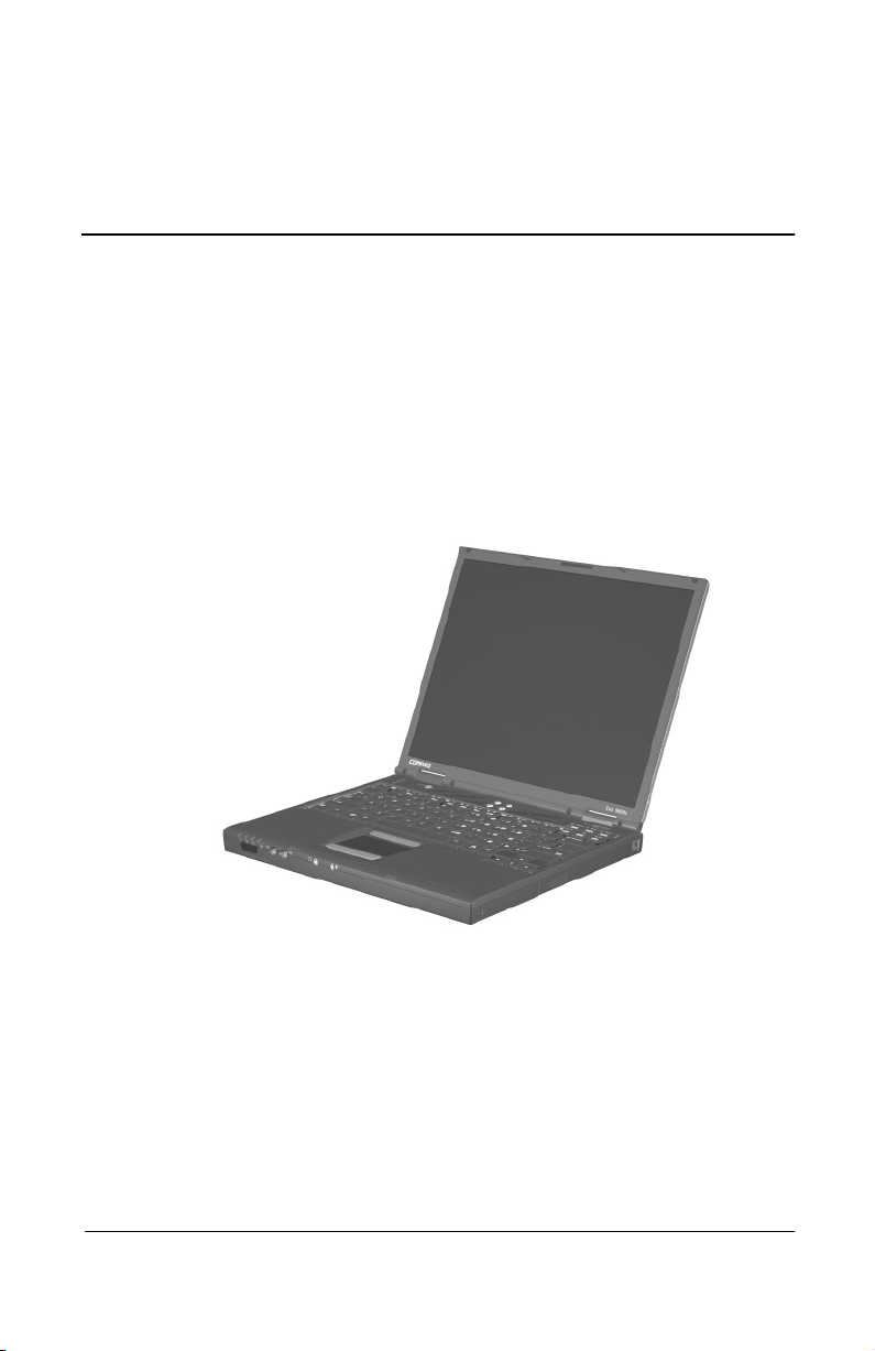
The Compaq Evo Notebook N610c and N600c Series offer
advanced modularity, Mobile Intel Pentium 4 and Pentium III
processors with 64-bit architecture, industry-leading Accelerated
Graphics Port (AGP) implementation, and extensive multimedia
support.
Figure 1-1. Compaq Evo Notebook N610c
Maintenance and Service Guide 1–1
Page 7

Product Description
1.1 Models
Computer models are shown in Tables 1-1 through 1-3.
Table 1-1
Compaq Evo Notebook N610c
Model Naming Conventions
Key
N610 P4 200 P4 40 V C 25 O XXXXXX-XXX
123456789 10
Key Description Options
1 Brand/Series
designator
2 Processor type P4=Pentium 4 P3=Pentium III
3 Processor speed 200=2.0 Ghz
4 Display type/
size/resolution
5 Hard drive size 40=40 GB
6 Optical drive
designator
7 Integrated
communication
8 RAM 51=512 MB
9 Operating system 8=Windows 98 SE
10 SKU#
N=Notebook 610=610c series
600=600c series
160=1.6 GHz
190=1.9 GHz
180=1.8 GHz
170=1.7 GHz
P=SXGA+ (1400 × 1050)
X=XGA (1024 × 768)
30=30 GB
20=20 GB
V=DVD-ROM drive
W=DVD-RW drive
M=Modem
0=None
38=384 MB
6=Windows 2000 and
Windows XP
106=1.06 GHz
866=866 MHz
4=14.x-inch
15=15 GB
10=10 GB
D=CD-ROM drive
R=CD-RW drive
C=Modem/NIC
combination card
25=256 MB
12=128 MB
2=Windows 2000
O=Windows XP Pro
E=Windows XP Home
1–2 Maintenance and Service Guide
Page 8

Product Description
Table 1-2
Compaq Evo Notebook N610c Models
The following Evo Notebook N610c models use config. code KT81 and feature:
■
Dual Stick pointing device (TouchPad and pointing stick)
■
8-cell, 4.0-Ah lithium ion (Li ion) battery pack
■
3-year warranty
■
32 MB of discrete video memory
■
No system memory
■
No optical drive
N610 P4 180 X4 30 0 C 0 O KT81
United States 470037-549
N610 P4 180 X4 30 0 C 0 2 KT81
United States 470037-542
The following Evo Notebook N610c models use config. code KT8Z and feature:
■
Dual Stick pointing device (TouchPad and pointing stick)
■
8-cell, 4.0-Ah lithium ion (Li ion) battery pack
■
3-year warranty
■
32 MB of discrete video memory
N610 P4 200 P4 40 W C 25 O
French Canada 470037-757 United States 470037-755
N610 P4 200 P4 40 W C 25 2
French Canada 470037-754 United States 470037-749
Maintenance and Service Guide 1–3
Page 9

Product Description
Table 1-2
Compaq Evo Notebook N610c Models
N610 P4 180 X4 30 V C 25 O
(Continued)
Asia Pacific
Australia
Belgium
Brazil
Czech Republic
Denmark
France
French Canada
Germany
Greece/Poland
Hong Kong
Hungary
Israel
Italy
Japan
Japan (English)
Korea
Latin America
Latin America
(GEM/NAFTA)
470037-714
470037-713
470037-687
470037-712
470037-688
470037-689
470037-690
470037-685
470037-691
470037-692
470037-717
470037-693
470037-694
470037-695
470037-707
470037-708
470037-718
470037-710
470037-747
The Netherlands
Norway
People’s
Republic of
China
Portugal
Russia
Saudi Arabia
Slovenia
Spain
Sweden/Finland
Switzerland
Ta i wa n
Tu r ke y
United Kingdom
United States
United States
(GEM/NAFTA)
470037-696
470037-697
470037-709
470037-699
470037-700
470037-686
470037-701
470037-702
470037-703
470037-704
470037-715
470037-705
470037-706
470037-684
and
470037-722
470037-746
1–4 Maintenance and Service Guide
Page 10
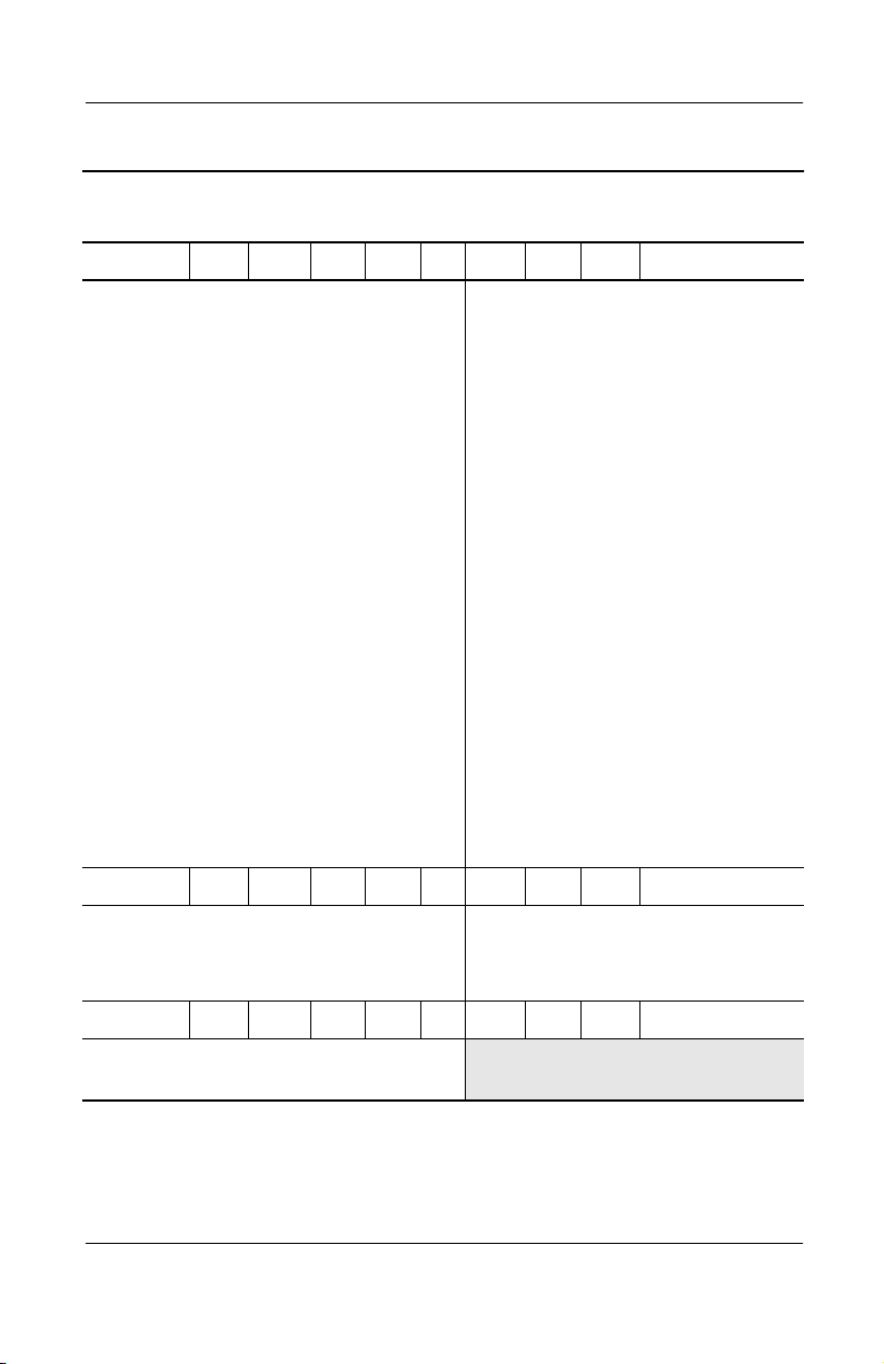
Table 1-2
Compaq Evo Notebook N610c Models
N610 P4 180 X4 30 V C 25 2
(Continued)
Product Description
Asia Pacific
Australia
Belgium
Brazil
Czech Republic
Denmark
France
French Canada
Germany
Greece/Poland
Hong Kong
Hungary
Israel
Italy
Japan
Japan (English)
Korea
Latin America
Latin America
(GEM/NAFTA)
N610 P4 160 X4 20 V C 25 O
French Canada 470037-736 United States
470037-572
470037-570
470037-529
470037-569
470037-530
470037-531
470037-532
470037-527
470037-533
470037-535
470037-584
470037-537
470037-538
470037-539
470037-561
470037-563
470037-587
470037-566
470037-726
The Netherlands
Norway
People’s
Republic of
China
Portugal
Russia
Saudi Arabia
Slovenia
Spain
Sweden/Finland
Switzerland
Ta i wa n
Tu r ke y
United Kingdom
United States
United States
(GEM/NAFTA)
United States
(GEM/NAFTA)
470037-541
470037-543
470037-577
470037-545
470037-546
470037-528
470037-548
470037-551
470037-552
470037-555
470037-580
470037-556
470037-558
470037-525
and
470037-720
470037-724
470037-733
470037-738
N610 P4 160 X4 20 V C 25 2
United States
(GEM/NAFTA)
470037-738
Maintenance and Service Guide 1–5
Page 11

Product Description
Table 1-2
Compaq Evo Notebook N610c Models
N610 P4 160 X4 20 D C 25 O
(Continued)
Belgium
Czech Republic
Denmark
France
Germany
Greece/Poland
Hungary
Israel
Italy
The Netherlands
N610 P4 160 X4 20 D C 25 2
Belgium
Czech Republic
Denmark
France
French Canada
Germany
Greece/Poland
Hungary
Israel
Italy
The Netherlands
470037-619
470037-620
470037-621
470037-622
470037-623
470037-625
470037-627
470037-630
470037-633
470037-636
470037-567
470037-571
470037-573
470037-578
470037-664
470037-581
470037-585
470037-586
470037-588
470037-595
470037-601
Norway
Portugal
Russia
Saudi Arabia
Slovenia
Spain
Sweden/Finland
Switzerland
Tu r ke y
United Kingdom
Norway
Portugal
Russia
Saudi Arabia
Slovenia
Spain
Sweden/Finland
Switzerland
Tu r ke y
United Kingdom
United States
470037-639
470037-641
470037-644
470037-618
470037-646
470037-648
470037-650
470037-653
470037-656
470037-658
470037-602
470037-604
470037-605
470037-562
470037-606
470037-607
470037-608
470037-613
470037-616
470037-617
470037-661
1–6 Maintenance and Service Guide
Page 12

Product Description
Table 1-3
Compaq Evo Notebook N600c Models
The following Evo Notebook N600c models use config. code KBSZ and
feature:
■
Dual Stick pointing device (TouchPad and pointing stick)
■
8-cell, 4.0-Ah lithium ion (Li ion) battery pack
■
3-year warranty
■
32 MB of discrete video memory
N600 P3 100 X4 20 D C 25 6
Greece/Poland
Hungary
Portugal
470029-002
470029-054
470029-056
Russia
Tu r ke y
N600 P3 100 X4 20 D C 12 8
Belgium
Czech Republic
Denmark
France
Germany
Greece/Poland
Hungary
Israel
Italy
The Netherlands
Norway
Portugal
470029-930
470029-936
470029-939
470029-941
470029-945
470029-951
470029-982
470029-983
470029-984
470029-986
470029-987
470029-988
Russia
Saudi Arabia
Slovakia/
Slovenia
Spain
Sweden/Finland
Switzerland
Tu r ke y
United Kingdom
470029-058
470029-060
470029-989
470029-985
470029-990
470029-991
470029-992
470029-993
and
470029-995
470029-996
470029-997
Maintenance and Service Guide 1–7
Page 13

Product Description
Table 1-3
Compaq Evo Notebook N600c Models
N600 P3 100 X4 20 D C 12 6
(Continued)
Belgium
Czech Republic
Denmark
France
Germany
Israel
Italy
The Netherlands
Norway
N600 P3 100 X4 20 D 0 25 O
European
International
N600 P3 100 X4 20 D 0 25 8
European
International
470029-192
470029-195
470029-207
470029-212
470029-214
470029-217
470029-224
470029-227
470029-228
470030-001
470029-998
Saudi Arabia
Slovakia/
Slovenia
Spain
Sweden/Finland
Switzerland
United Kingdom
470029-226
470029-231
470029-232
470029-234
470029-238
and
470029-240
470029-242
1–8 Maintenance and Service Guide
Page 14

1.2 Features
■
The following processors are available, varying by notebook
model:
❏
The Evo Notebook N610c features a Mobile Intel
Pentium 4 2.0-, 1.9-, 1.8-, 1.7-, or 1.6-GHz processor,
with 512-KB integrated L2 cache.
❏
The Evo Notebook N600c features a Mobile Intel
Pentium III 1.066 GHz-M or 866-MHz-M processor,
with 512-KB integrated L2 cache.
■
ATI Mobility Radeon with 64-bit video graphics,
16-MB double date rate (DDR) SDRAM, 4X AGP
graphics card
■
The following memory configurations are available, varying
by notebook model:
❏
The Evo Notebook N610c features 256-MB
high-performance Synchronous DRAM (SDRAM),
expandable to 2048 MB
Product Description
❏
The Evo Notebook N600c features 256- or 128-MB
high-performance Synchronous DRAM (SDRAM),
expandable to 1024 MB
■
Microsoft Windows 98 SE, Windows 2000, or Windows XP
preinstalled, varying by notebook model
■
14.1-inch, SXGA+ (1400 × 1050) or XGA (1024 × 768),
TFT display with over 16.8 million colors, varying by
computer model
■
Full-size TouchPad or Dual Stick keyboard, varying by
notebook model
■
Mini PCI 10/100 network interface card (NIC) or Mini
PCI V.90 modem plus 10/100 NIC combination card,
varying by notebook model
■
Support for two Type II PC Card slots with support for both
32-bit CardBus and 16-bit PC Cards
Maintenance and Service Guide 1–9
Page 15

Product Description
■
External AC adapter with power cord
■
8-cell Lithium ion (Li ion) battery pack
■
40-, 30-, 20-, 15-, or 10-GB high-capacity hard drive
■
Connectors for:
❏
❏
❏
❏
❏
❏
❏
❏
❏
❏
❏
RJ-11 modem
Mono microphone
Stereo line-out/headphone
MultiPort
Universal serial bus (USB)
Docking
Parallel devices
Serial devices
Composite TV
External keyboard/mouse
RJ-45 network
❏
External monitor
❏
AC power
■
Stereo speakers providing Compaq Premier·Sound 16-bit
stereo sound
1.3 Clearing a Password
If the notebook you are servicing has an unknown password,
follow these steps to clear the password. These steps also
clear CMOS.
1. Prepare the notebook for disassembly (refer to Section 5.3,
“Preparing the Notebook for Disassembly,” for more
information).
1–10 Maintenance and Service Guide
Page 16

2. Remove the RTC battery (refer to Section 5.6, “Disk Cell
RTC Battery”).
3. Wait approximately five minutes.
4. Replace the RTC battery and reassemble the notebook.
5. Connect AC power to the notebook. Do not reinsert any
battery packs at this time.
6. Turn on the notebook.
All passwords and all CMOS settings have been cleared.
1.4 Power Management
The notebook comes with power management features that
extend battery operating time and conserve power. The notebook
supports the following power management features:
■
Standby
■
Hibernation
Product Description
■
Setting customization by the user
■
Hotkeys for setting level of performance
■
Smart battery that provides an accurate battery power gauge
■
Battery calibration
■
Lid switch suspend/resume
■
Power/suspend button
■
Advanced Configuration and Power Management (ACP)
compliance
Maintenance and Service Guide 1–11
Page 17
Product Description
1.5 Notebook External Components
The external components on the front and right side of the
Evo Notebook N610c and Evo Notebook N600c are shown in
Figure 1-2 and described in Table 1-4.
.
Figure 1-2. Front and Right Side Components
Table 1-4
Front and Right Side Panel Components
Item Component Function
1 Power light On: Power is turned on.
Blinking: Notebook is in Standby. The power
light also blinks if a battery pack that is the
only available power source reaches a
low-battery condition.
2 Battery light On: A battery pack is charging.
Blinking: A battery pack that is the only
available power source has reached a
low-battery condition.
1–12 Maintenance and Service Guide
Page 18

Product Description
Table 1-4
Front and Right Side Panel Components
Item Component Function
3 Drive activity light Turns on when the hard drive, CD-, or
DVD-ROM drive is accessed.
4 Media Bay light Turns on when the diskette drive in the Media
Bay or the optional external diskette drive is
accessed.
5 Infrared port Links to another IrDA-compliant device for
wireless communication.
6 Volume control buttons Adjust the volume of the stereo speakers.
7 Stereo line-out/
headphone jack
8 Mono microphone jack Connects a mono microphone, disabling the
9 Display release latch Opens the notebook.
10 Security cable slot Attaches an optional security cable to the
Connects stereo speakers, headphones,
headset, or television audio.
built-in microphone.
notebook.
(Continued)
11 Media Bay Accepts a diskette drive, CD- or DVD-ROM
drive, or secondary battery pack.
12 RJ-11 jack (internal
modem models only)
Connects the modem cable to an internal
modem. A modem cable is included with
internal modem models.
Maintenance and Service Guide 1–13
Page 19
Product Description
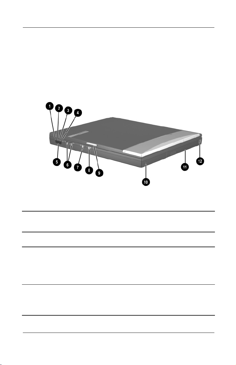
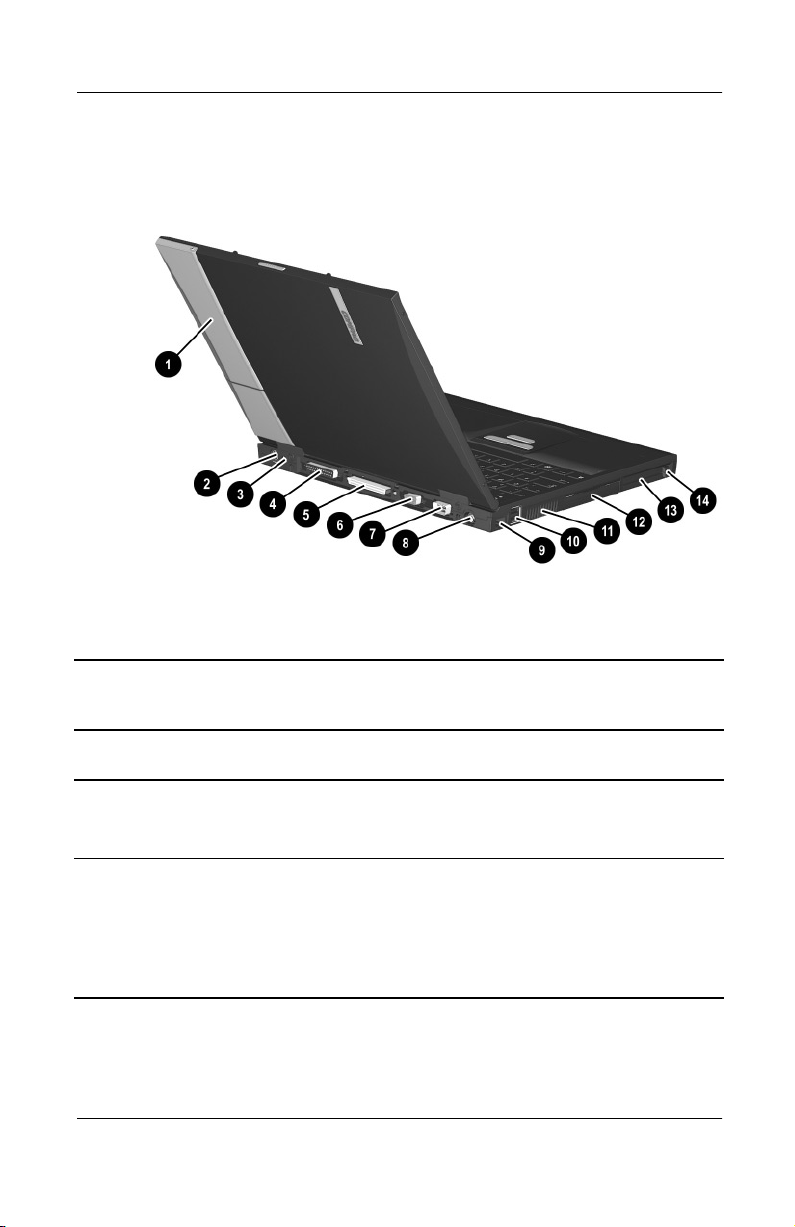
The Evo Notebook N610c right side and rear panel components
are shown in Figure 1-3 and described in Table 1-5.
Figure 1-3. Right Side and Rear Panel Components—
Evo Notebook N610c
Table 1-5
Right Side and Rear Panel Components
Item Component Function
1 DC power jack Connects any one of the following:
■
AC adapter
■
Optional automobile power
adapter/charger
■
Optional aircraft power adapter
2 Keyboard/mouse
connector
1–14 Maintenance and Service Guide
Connects an external keyboard or
PS/2-compatible external mouse. To connect
a keyboard and a mouse at the same time,
use an optional Y-adapter.
Page 20

Table 1-5
Right Side and Rear Panel Components
Item Component Function
3 Parallel connector Connects a parallel device.
4 USB connectors (2) Connect USB devices.
(Continued)
Product Description
5RJ-45 jack (network
models only)
6 Serial connector Connects a serial device.
7 External monitor
connector
8 S-Video connector Connects a television, VCR, camcorder, or
9 Vent Allows airflow to cool internal components.
10 Hard drive Supports the removable primary hard drive.
11 PC Card slots Support a 32-bit (CardBus) or 16-bit
12 PC Card eject buttons Eject a PC Card from a PC Card slot.
Connects the network cable. A network cable
is not included with the notebook.
Connects an external monitor or overhead
projector.
overhead projector.
To prevent damage, the notebook
Ä
shuts down if an overheating
condition occurs. Do not block the
cooling vent. Avoid placing the
notebook on a blanket, rug, or other
flexible surface that may cover the
vent area.
PC Card.
Maintenance and Service Guide 1–15
Page 21
Product Description
The Evo Notebook N600c right side and rear panel components
are shown in Figure 1-4 and described in Table 1-6.
Figure 1-4. Right Side and Rear Panel Components—
Evo Notebook N600c
Table 1-6
Right Side and Rear Panel Components
Item Component Function
1 MultiPort Connects wireless communication devices,
such as an optional Bluetooth or 802.11b
MultiPort module, and other options.
2 DC power jack Connects any one of the following:
■
AC adapter
■
Optional automobile power
adapter/charger
■
Optional aircraft power adapter
1–16 Maintenance and Service Guide
Page 22

Table 1-6
Right Side and Rear Panel Components
Item Component Function
Product Description
(Continued)
3 Keyboard/mouse
connector
4 Parallel connector Connects a parallel device.
5 Docking connector Connects the computer to the optional
6 Serial connector Connects a serial device.
7 External monitor
connector
8 S-Video connector Connects a television, VCR, camcorder, or
9RJ-45 jack (network
models only)
10 USB connectors (2) Connect USB devices.
11 Vent Allows airflow to cool internal components.
Connects an external keyboard or
PS/2-compatible external mouse. To connect
a keyboard and a mouse at the same time,
use an optional Y-adapter.
expansion base, convenience base, or port
replicator.
Connects an external monitor or overhead
projector.
overhead projector.
Connects the network cable. A network cable
is not included with the computer.
To prevent damage, the notebook
Ä
shuts down if an overheating
condition occurs. Do not block the
cooling vent. Avoid placing the
notebook on a blanket, rug, or other
flexible surface that may cover the
vent area.
12 Hard drive Supports the removable primary hard drive.
13 PC Card slots Support 32-bit (CardBus) or 16-bit PC Cards.
14 PC Card eject buttons Eject PC Cards from the PC Card slots.
Maintenance and Service Guide 1–17
Page 23
Product Description
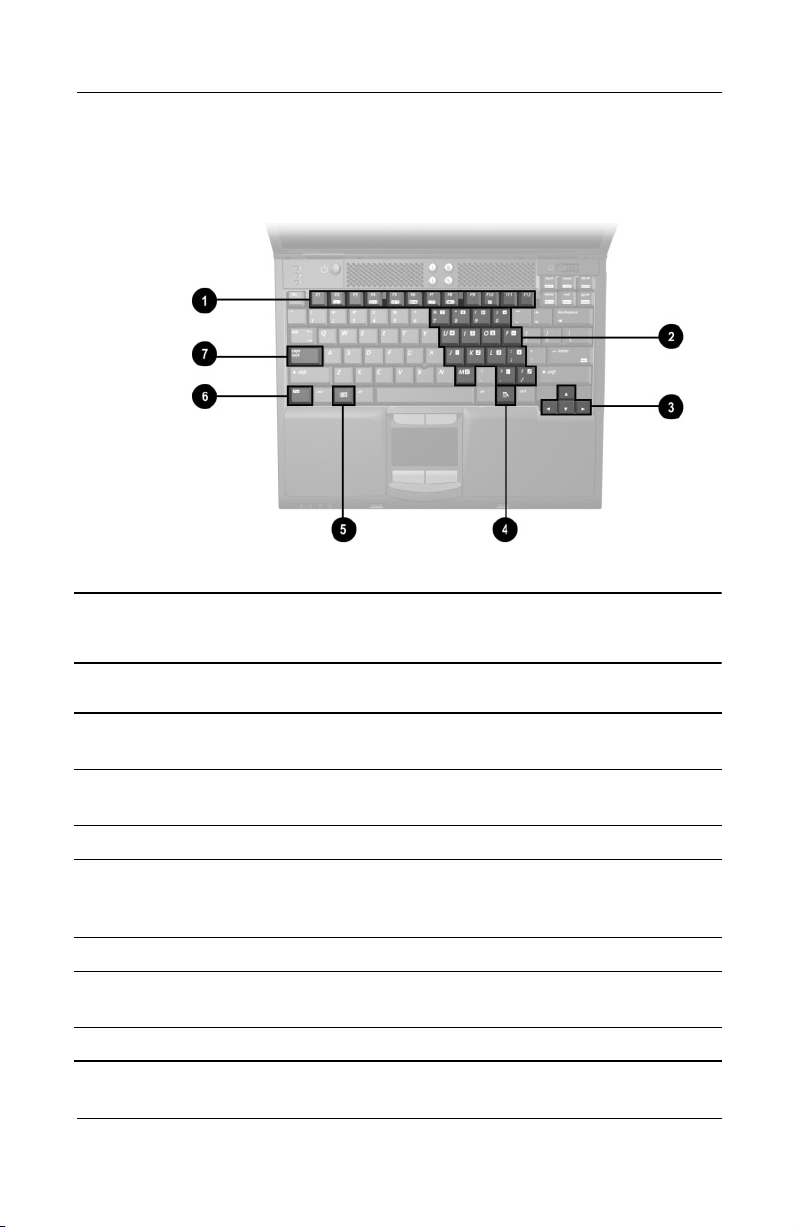
The keyboard components of the Evo Notebook N610c and
Evo Notebook N600c are shown in Figure 1-5 and described in
Table 1-7.
Figure 1-5. Keyboard Components
Table 1-7
Keyboard Components
Item Component Function
1
2 Embedded numeric
3 Cursor control keys Move the cursor around the screen.
4 Windows
5 Windows logo key Displays the Windows Start menu.
6
7 Caps lock key Turns on the caps lock function.
1–18 Maintenance and Service Guide
through
F1
function keys
keypad
application key
key Used with hotkeys to perform preset hotkey
Fn
F12
Perform preset functions.
Converts keys to a numeric keypad.
Displays a menu when using a Microsoft
application. The menu is the same one that is
displayed by pressing the right mouse button.
functions.
Page 24
Product Description
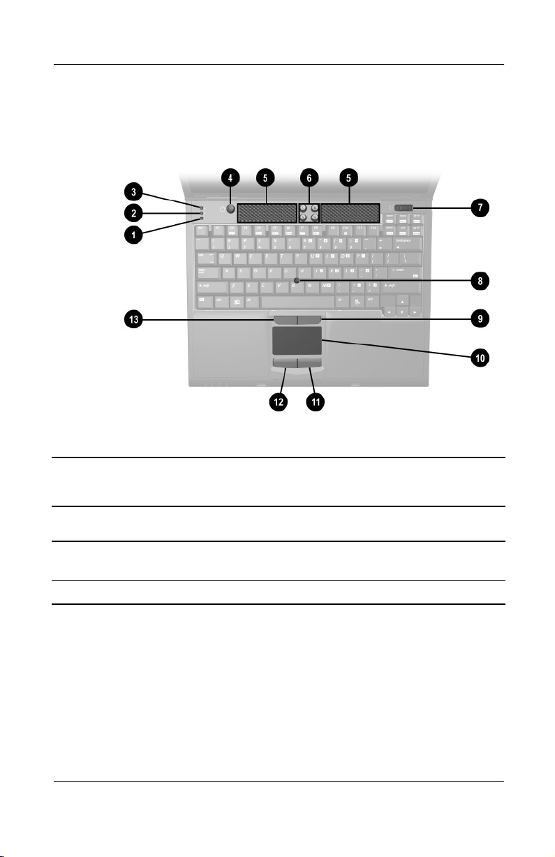
The components on the top of the Evo Notebook N610c and
Evo Notebook N600c are shown in Figure 1-6 and described in
Table 1-8.
Figure 1-6. Top Components
Table 1-8
Top Components
Item Component Function
1 Num lock light On: Num lock is on and the embedded
numeric keypad is enabled.
2 Scroll lock light On: Scroll is on.
Maintenance and Service Guide 1–19
Page 25

Product Description
Table 1-8
Top Components
Item Component Function
3 Caps lock light On: Caps lock is on.
4 Standby button Turns on the notebook if it is off.
Initiates and exits Standby.
When pressed with the
Hibernation.
5 Stereo speakers (2) Produce stereo sound.
6 Easy Access buttons (4) Provide quick access to the Internet. Refer
to the
notebook for information about these
buttons.
7 Power switch Turns on the notebook. To turn off the
notebook, use the operating system
Shut Down command.
8 Pointing stick Moves the mouse cursor.
(Continued)
Hardware Guide
key, initiates
Fn
that ships with the
9 Right pointing stick
button
10 TouchPad Moves the mouse cursor.
11 Right TouchPad button Functions like the right mouse button on an
12 Left TouchPad button Functions like the left mouse button on an
13 Left pointing stick button Functions like the left mouse button on an
Functions like the right mouse button on an
external mouse.
external mouse.
external mouse.
external mouse.
1–20 Maintenance and Service Guide
Page 26
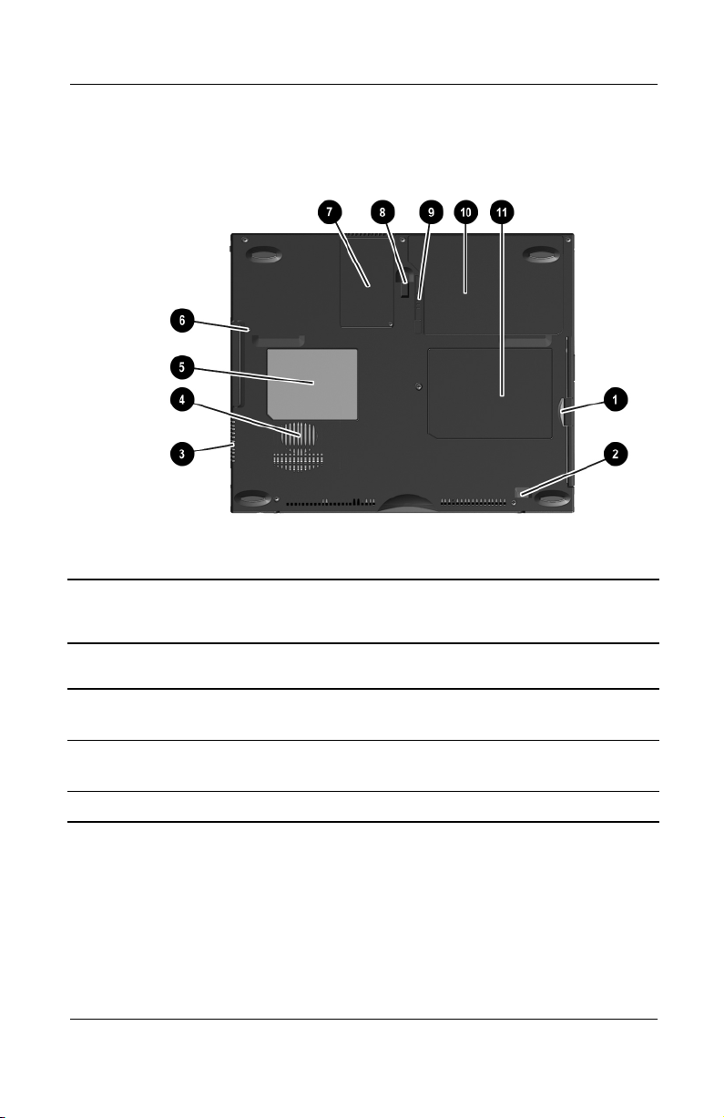
Product Description
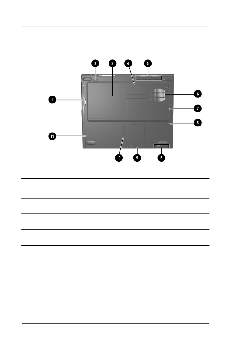
The Evo Notebook N610c bottom components are shown in
Figure 1-7 and described in Table 1-9.
Figure 1-7. Bottom Components—Evo Notebook N610c
Table 1-9
Bottom Components
Item Component Function
1 Media Bay Accepts a diskette drive, CD- or DVD-ROM
drive, or secondary battery pack.
2 Media Bay release latch Releases the Media Bay device from the
connector.
Maintenance and Service Guide 1–21
Page 27

Product Description
Table 1-9
Bottom Components
Item Component Function
3 Serial number Identifies the notebook; needed when you
call Compaq customer support.
4 Docking connector Connects the notebook to the optional
expansion base, convenience base, or port
replicator.
5 Air vents (2) Allow airflow to cool internal components.
6 Fan Provides airflow to cool internal
components.
7 Hard drive Supports the removable primary hard drive.
(Continued)
8 Hard drive security
screw
9 Mini PCI compartment
cover
10 Battery release latch Releases the battery pack from the battery
11 Battery compartment Holds the battery pack.
Secures the hard drive.
Covers the memory expansion
compartment that contains two memory
expansion slots for memory expansion
boards.
compartment.
1–22 Maintenance and Service Guide
Page 28
Product Description
The Evo Notebook N600c bottom components are shown in
Figure 1-8 and described in Table 1-10.
Figure 1-8. Bottom Components—Evo Notebook N600c
Table 1-10
Bottom Components
Item Component Function
1 Media Bay Accepts a diskette drive, optical drive, or
secondary battery pack.
2 Media Bay release latch Releases the Media Bay device from the
connector.
3 Vent Allows airflow to cool internal components.
Maintenance and Service Guide 1–23
Page 29

Product Description
Table 1-10
Bottom Components
Item Component Function
4 Fan Provides airflow to cool internal
components.
(Continued)
5 Certificate of
Authenticity label
6 Hard drive security
screw
7 Memory expansion
compartment cover
8 Docking recess latch Secures the computer to an optional
9 Battery release latch Releases the battery pack from the battery
10 Battery compartment Holds the battery pack.
11 Serial number Identifies the computer; needed when you
Contains the Product Key, which may need
to be entered before using some Windows
operating systems.
Secures the hard drive.
Covers the memory expansion
compartment that contains two memory
expansion slots for memory expansion
boards.
expansion base, convenience base, or port
replicator.
compartment.
call Compaq customer support.
1–24 Maintenance and Service Guide
Page 30

1.6 Design Overview
This section presents a design overview of key parts and features
of the notebook. Refer to Chapter 3, “Illustrated Parts Catalog,” to
identify replacement parts, and Chapter 5, “Removal and
Replacement Procedures,” for disassembly steps. The system
board provides the following device connections:
■
Memory expansion board
■
Hard drive
■
Display
■
Keyboard/TouchPad or pointing stick
■
Audio
■
Intel Pentium 4 and Pentium III processors
■
Fan
■
PC Card
■
Modem or modem/NIC
Product Description
The notebook uses an electrical fan for ventilation. The fan is
controlled by a temperature sensor and is designed to turn on
automatically when high temperature conditions exist. These
conditions are affected by high external temperatures, system
power consumption, power management/battery conservation
configurations, battery fast charging, and software applications.
Exhaust air is displaced through the ventilation grill located on
the left side of the notebook.
CAUTION: To properly ventilate the notebook, allow at least a
Ä
7.6-cm (3-inch) clearance on the left and right sides of the notebook.
Maintenance and Service Guide 1–25
Page 31

Troubleshooting
WARNING: Only authorized technicians trained by Compaq should
Å
repair this equipment. All troubleshooting and repair procedures
are detailed to allow only subassembly/module level repair.
Because of the complexity of the individual boards and
subassemblies, no one should attempt to make repairs at the
component level or make modifications to any printed wiring board.
Improper repairs can create a safety hazard. Any indication of
component replacement or printed wiring board modification may
void any warranty or exchange allowances.
2.1 Computer Setup and Diagnostics Utilities
Selecting Computer Setup or Compaq Diagnostics
2
The computer features two Compaq system management utilities:
■
Computer Setup—A system information and customization
utility that can be used even when your operating system is
not working or will not load. This utility includes settings that
are not available in Windows.
Maintenance and Service Guide 2–1
Page 32

Troubleshooting
■
Compaq Diagnostics—A system information and diagnostic
utility that is used within your Windows operating system.
Use this utility whenever possible to:
❏
Display system information.
❏
Test system components.
❏
Troubleshoot a device configuration problem
in Windows 2000, Windows XP Professional, or
Windows XP Home.
Using Computer Setup
Information and settings in Computer Setup are accessed from
the File, Security, or Advanced menus:
1. Turn on or restart the computer. Press
while the
F10
F10 = ROM Based Setup message is displayed in the
lower-left corner of the screen.
❏
To change the language, press
❏
To view navigation information, press
❏
To return to the Computer Setup menu, press
F2.
F1.
esc.
2. Select the File, Security, or Advanced menu.
3. To close Computer Setup and restart the computer:
❏
Select File > Save Changes and Exit and press
enter.
or
❏
Select File > Ignore Changes and Exit and press
4. When you are prompted to confirm your action, press
enter.
F10.
2–2 Maintenance and Service Guide
Page 33

Selecting from the File Menu
Table 2-1
File Menu
Select To Do This
Troubleshooting
System Information ■
Save to Floppy Save system configuration settings to a diskette.
Restore from Floppy Restore system configuration settings from a
Restore Defaults Replace configuration settings in Computer Setup
Ignore Changes and Exit Cancel changes entered during the current
Save Changes and Exit Save changes entered during the current session,
View identification information about the
computer, a docking base, and any battery
packs in the system.
■
View specification information about the
processor, memory and cache size, and
system ROM.
diskette.
with factory default settings. (Identification
information is retained.)
session, then exit and restart the computer.
then exit and restart the computer.
Maintenance and Service Guide 2–3
Page 34

Troubleshooting
Selecting from the Security Menu
Table 2-2
Security Menu
Select To Do This
Setup Password Enter, change, or delete a setup password.
(The setup password is called an administrator
password in Compaq Computer Security, a
program accessed from the Windows Control
Panel.)
Power-on Password Enter, change, or delete a power-on password.
DriveLock Passwords Enable/disable DriveLock; change a DriveLock
User or Master password.
Drive Lock Settings are accessible only
✎
when you enter Computer Setup by
turning on (not restarting) the computer.
Password Options
Password options can be
selected only when a
power-on password has
been set.
Device Security Enable/disable:
System IDs Enter identification numbers for the computer, a
*Not applicable to SuperDisk LS-120 drives.
2–4 Maintenance and Service Guide
Enable/disable:
■
QuickLock
■
QuickLock on Standby
■
QuickBlank
To enable QuickLock on Standby or
✎
QuickBlank, you must first enable
QuickLock.
■
Ports or diskette drives*
■
Diskette write*
■
CD-ROM or diskette startup
Settings for a DVD-ROM can be
✎
entered in the CD-ROM field.
docking base, and all battery packs in the system.
Page 35

Selecting from the Advanced Menu
Table 2-3
Advanced Menu
Select To Do This
Troubleshooting
Language (or press
Boot Options Enable/disable:
Device Options ■
) Change the Computer Setup language.
F2
■
QuickBoot, which starts the computer more
quickly by eliminating some startup tests.
(If you suspect a memory failure and want to
test memory automatically during startup,
disable QuickBoot.)
■
MultiBoot, which sets a startup sequence
that can include most bootable devices and
media in the system.
Enable/disable the embedded numeric
keypad at startup.
■
Enable/disable multiple standard pointing
devices at startup. (To set the computer to
support only a single, usually nonstandard,
pointing device at startup, select Disable.)
■
Enable/disable USB legacy support for a
USB keyboard. (When USB legacy support
is enabled, the keyboard works even when a
Windows operating system is not loaded.)
■
Set an optional external monitor or overhead
projector connected to a video card in a
docking base as the primary device. (When
the computer display is set as secondary,
the computer must be shut down before
undocking from a docking base.)
Maintenance and Service Guide 2–5
Page 36

Troubleshooting
Table 2-3
Advanced Menu
Select To Do This
(Continued)
Device Options
(continued)
■
Change the parallel port mode from
Enhanced Parallel Port (EPP, the default
setting) to standard, bidirectional, EPP or
Enhanced Capabilities Port (ECP).
■
Set video-out mode to NTSC (default), PAL,
NTSC-J, or PAL-M.*
■
Enable/disable all settings in the SpeedStep
window. (When Disable is selected, the
computer runs in Battery Optimized mode.)
■
Specify how the computer recognizes
multiple identical docking bases that are
identically equipped. (Select Disable to
recognize the docking bases as a single
docking base; select Enable to recognize
the docking bases individually, by serial
number.)
■
Enable/disable the reporting of the
processor serial number by the processor to
the software.
HDD Self Test Options Run a quick comprehensive self test on hard
drives in the system that support the test
features.
* Video modes vary even within regions. However, NTSC is common in
North America; PAL, in Europe, Africa, and the Middle East; NTSC-J, in Japan;
and PAL-M, in Brazil. Other South and Central American regions may use
NTSC, PAL, or PAL-M.
2–6 Maintenance and Service Guide
Page 37

Troubleshooting
2.2 Using Compaq Diagnostics
When you access Compaq Diagnostics, a scan of all system
components is displayed on the screen before the Compaq
Diagnostics window opens.
You can display more or less information from anywhere within
Compaq Diagnostics by selecting Level on the menu bar.
Compaq Diagnostics is designed to test Compaq components. If
non-Compaq components are tested, the results may be
inconclusive.
Obtaining, Saving, or Printing Configuration Information
1. Access Compaq Diagnostics by selecting Start > Settings >
Control Panel > Compaq Diagnostics.
2. Select Categories, then select a category from the
drop-down list.
❏
To save the information, select File > Save As.
❏
To print the information, select File > Print.
3. To close Compaq Diagnostics, select File > Exit.
Maintenance and Service Guide 2–7
Page 38

Troubleshooting
Obtaining, Saving, or Printing Diagnostic Test Information
1. Access Compaq Diagnostics by selecting Start > Settings >
Control Panel > Compaq Diagnostics.
2. Select the Test tab.
3. In the scroll box, select the category or device you want
to test.
4. Select a test type:
❏
Quick Test—Runs a quick, general test on each device in
a selected category.
❏
Complete Test—Performs maximum testing on each
device in a selected category.
❏
Custom Test—Performs maximum testing on a selected
device.
◆
To run all tests for your selected device, click
Check All.
◆
To run only the tests you select, click Uncheck All,
then select the checkbox for each test you want
to run.
2–8 Maintenance and Service Guide
Page 39

5. Select a test mode:
❏
Interactive Mode—Provides maximum control over the
testing process. You determine whether the test was
passed or failed, and you may be prompted to insert or
remove devices.
❏
Unattended Mode—Does not display prompts. If errors
are found, they are displayed when testing is complete.
6. Click Begin Testing.
7. Select a tab to view a test report:
❏
Status tab—Summarizes the tests run, passed, and failed
during the current testing session.
❏
Log tab—Lists tests run on the system, the number of
times each test has run, the number of errors found on
each test, and the total run time of each test.
❏
Error tab—Lists all errors found in the computer with
their error codes.
8. Select a tab to save the report:
Troubleshooting
❏
Log tab—Select Save.
❏
Error tab—Select Save.
9. Select a tab to print the report:
❏
Log tab—Select File > Save As, then print the file from
your folder.
Maintenance and Service Guide 2–9
Page 40

Troubleshooting
2.3 Troubleshooting Flowcharts
Tabl e 2 - 4
Troubleshooting Flowcharts Overview
Flowchart Description
2.1 Initial Troubleshooting
2.2 No Power, Part 1
2.3 No Power, Part 2
2.4 No Power, Part 3
2.5 No Power, Part 4
2.6 No Video, Part 1
2.7 No Video, Part 2
2.8 Nonfunctioning Docking Station
2.9 No Operating System (Os) Loading
2.10 No Os Loading From Hard Drive, Part 1
2.11 No Os Loading From Hard Drive, Part 2
2.12 No Os Loading From Hard Drive, Part 3
2.13 No Os Loading From Diskette Drive
2.14 No Os Loading From CD- Or DVD-ROM Drive
2.15 No Audio, Part 1
2.16 No Audio, Part 2
2.17 Nonfunctioning Device
2.18 Nonfunctioning Keyboard
2.19 Nonfunctioning Pointing Device
2.20 No Network Or Modem Connection
2–10 Maintenance and Service Guide
Page 41

Flowchart 2.1 - Initial Troubleshooting
Begin
troubleshooting.
N
Is there
power?
Y
N
Beeps,
LEDs, or error
messages?
Y
N
Is there video?
(no boot)
Y
N
Is the OS
loading?
Y
N
Is there
sound?
Y
Go to
Flowchart 2.2,
No Power, Part 1.
Check
LED board,
speaker
connections.
Go to
Flowchart 2.6,
No Video, Part 1.
Go to
Flowchart 2.9,
No OS Loading.
Go to
Flowchart 2.15,
No Audio.
All drives
working?
Y
Keyboard/
pointing
device
working?
Y
Connecting
to network
or modem?
Y
End
Troubleshooting
N
Flowchart 2.17,
Nonfunctioning
N
Flowchart 2.18,
Nonfunctioning
or Flowchart 2.19,
Nonfunctioning
Pointing Device.
N
Flowchart 2.20,
No Network or
Connection.
Go to
Device.
Go to
Keyboard,
Go to
Modem
Maintenance and Service Guide 2–11
Page 42

Troubleshooting
Flowchart 2.2 - No Power, Part 1
No power
(power LED
is off).
Remove from
docking station
(if applicable).
N
Power up
on battery
power?
*Reset
power.
Y
N
Power up
on AC
power?
*Reset
power.
Y
Y
Power up
in docking
station?
Done
N
1. Reseat the power cables in the docking
station and at the AC outlet.
2. Ensure that the AC power source is active.
3. Ensure that the power strip is working.
YN
Done
Power up
in docking
station?
N
Power up
on battery
power?
Go to
Flowchart 2.3,
No Power,
Part 2.
Y
N
Power up
on AC
power?
Go to
Flowchart 2.4,
No Power,
Part 3.
Y
* On some models there is a separate reset
button. On some models the computer may be
reset using the Standby switch and either the
lid switch or the main power switch.
Go to
Flowchart 2.8,
Nonfunctioning
Docking Station.
2–12 Maintenance and Service Guide
Page 43

Flowchart 2.3 - No Power, Part 2
Continued from
Flowchart 2.2,
No Power, Part 1.
Visually check for
debris in battery
socket and clean
if necessary.
Y
Troubleshooting
Power on?
N
Check battery by
recharging,
moving it to
another computer,
or replacing it.
Power on?
Y
Done
Done
N
Replace power
supply (if
applicable).
N
Go to
Power on?
Flowchart 2.4,
No Power,
Part 3.
Y
Done
Maintenance and Service Guide 2–13
Page 44

Troubleshooting
Flowchart 2.4 - No Power, Part 3
Continued from
Flowchart 2.3,
No Power, Part 2.
Plug directly
into AC outlet.
Y
Power LED
on?
N
Reseat AC adapter
in computer and
at power source.
Power on?
N
Power outlet
active?
Y
Replace
power cord.
Power on?
Done
Y
Done
N
Try different
outlet.
Internal or
external AC
Internal
Flowchart 2.5,
No Power,
Y
Done Done
adapter?
Go to
Part 4.
External
Replace external
AC adapter.
N
Power on?
Y
N
2–14 Maintenance and Service Guide
Page 45

Flowchart 2.5 - No Power, Part 4
Continued from
Flowchart 2.4,
No Power, Part 3.
Open
computer.
Troubleshooting
Loose or
damaged
parts?
N
Close
computer and
retest.
Power on?
Y
Done
Y
Reseat loose
components and
boards and
replace
damaged items.
N
Replace the following items (if applicable).
Check computer operation after each
replacement:
1. Internal DC-DC converter*
2. Internal AC adapter
3. Processor board*
4. System board*
*Replace these items as a set to prevent
shorting out among components.
Maintenance and Service Guide 2–15
Page 46

Troubleshooting
Flowchart 2.6 - No Video, Part 1
No video.
Docking
station
Stand-alone
or docking
station?
Go to
Flowchart 2.7,
No Video, Part 2.
* To change from internal to
external display, use the hotkey
combination.
Stand-alone
Y
Internal or
external
display*?
External
Adjust
brightness.
Internal
Y
Video OK? Done
N
Check for bent
pins on cable.
N
Video OK?
Adjust
brightness.
Video OK? Done
N
A
Press lid
switch to ensure
operation.
Y
Video OK? Done
N
Replace the following one at a time. Test after each replacement.
1. Cable between notebook and computer display (if applicable)
2. Inverter board (if applicable)
3. Display
4. System board
N
Try
another
display.
Internal and
external
video OK?
Replace
system
board.
YY
Done
2–16 Maintenance and Service Guide
Done
Page 47

Flowchart 2.7 - No Video, Part 2
Continued from
Flowchart 2.6,
No Video, Part 1.
Remove
notebook from
docking station,
if connected.
Troubleshooting
Adjust
display
brightness.
N
Go to “A” in
Video OK?
Flowchart 2.6,
No Video, Part 1.
Y
Check that notebook is properly
seated in docking station, for bent
pins on cable, and for monitor
connection.
Y
Video OK?
N
Adjust external
monitor display.
Done
Check brightness
of external
monitor.
Video OK?
N
Try another
external
monitor.
Internal
and external
video OK?
N
Go to
Flowchart 2.8,
Nonfunctioning
Docking Station.
Y
Done
Y
Done
Maintenance and Service Guide 2–17
Page 48

Troubleshooting
Flowchart 2.8 - Nonfunctioning Docking Station
(if applicable)
Nonfunctioning
docking station.
Reseat power
cord in docking
station and
power outlet.
Check voltage
setting on
docking station.
Reset monitor
cable connector at
docking station.
Docking
station
operating?
N
Remove
notebook, reseat
all internal parts,
and replace any
damaged items in
docking station.
Reinstall
notebook into
docking station.
Y
Docking
station
operating?
Done
N
Y
Done
Replace the following docking station
components one at a time. Check
computer operation after each
replacement.
1. Power supply
2. I/O board
3. Backplane board
4. Switch box
2–18 Maintenance and Service Guide
Page 49

Troubleshooting
Flowchart 2.9 - No Operating System (OS) Loading
No OS
loading.*
Reseat power
cord in docking
station and
power outlet.
* Before beginning troubleshooting, always
check cable connections, cable ends, and
drives for bent or damaged pins.
No OS loading
from hard drive,
go to Flowchart 2.10,
No OS Loading from
Hard Drive, Part 1.
No OS loading
from diskette drive,
go to Flowchart 2.13,
No OS Loading from
Diskette Drive.
No OS loading
from CD- or
DVD-ROM drive,
go to Flowchart 2.14,
No OS Loading
from CD- or
DVD-ROM Drive.
Maintenance and Service Guide 2–19
Page 50

Troubleshooting
Flowchart 2.10 - No OS Loading from Hard Drive, Part 1
OS not
loading from
hard drive.
Nonsystem
disk message?
N
Reseat
external
hard drive.
OS loading?
N
Boot
from
CD?
Y
Check the setup
utility for correct
booting order.
Y
Go to
Flowchart 2.11,
No OS Loading
from Hard Drive,
Part 2.
Y
Done
N
N
Boot
from
diskette?
Y
Go to
Flowchart 2.13,
No OS
Loading from
Diskette Drive.
N
Boot
from
hard drive?
Y
Done
Change boot
priority through
the setup utility
and reboot.
Boot
from
hard drive?
N
Go to
Flowchart 2.17,
Nonfunctioning
Device.
Y
2–20 Maintenance and Service Guide
Page 51

Troubleshooting
Flowchart 2.11 - No OS Loading from Hard Drive, Part 2
Continued from
Flowchart 2.10,
No OS Loading
from Hard Drive,
Part 1.
CD or
diskette in
drive?
Y
Remove
diskette and
reboot.
N
1. Replace hard
drive.
2. Replace system
board.
accessible?
N
Run FDISK.
Reseat
hard drive.
Hard drive
Y
Done
Boot
from
hard drive?
N
Boot
from diskette
drive?
Y
Hard drive
accessible?
Y
Go to
Flowchart 2.12,
No OS Loading
from Hard Drive,
Part 3.
Y
N
Flowchart 2.13,
No OS Loading
N
Done
Go to
from Diskette
Drive.
Done
Hard drive
partitioned?
Y
Hard drive
formatted?
Y
Y
Computer
booted?
Go to
Flowchart 2.12,
No OS Loading
from Hard Drive,
Part 3.
N
Create partition,
then format hard
drive to bootable
C:\ prompt.
N
Format hard drive
and bring to a
bootable C:\
prompt.
Load OS using
Restore CD (if
applicable).
N
Maintenance and Service Guide 2–21
Page 52

Troubleshooting
Flowchart 2.12 - No OS Loading from Hard Drive, Part 3
Continued from
Flowchart 2.11,
No OS Loading
from Hard Drive,
Part 2.
N
System
files on hard
drive?
Y
Install OS
and reboot.
Virus
on hard
drive?
N
Run SCANDISK
and check for
bad sectors.
Can bad
sectors
be fixed?
Y
Fix bad
sectors.
Y
Clean virus.
OS
loading from
hard drive?
Y
Done
N
Y
Diagnostics
on diskette?
Replace
hard drive.
N
N
Replace
hard drive.
Run diagnostics
and follow
recommendations.
N
Boot from
hard drive?
Replace
hard drive.
Y
Done
2–22 Maintenance and Service Guide
Page 53

Troubleshooting
Y
Flowchart 2.13 - No OS Loading from Diskette Drive
OS not loading
from
diskette drive.
Nonsystem
disk message?
Boot
from another
device?
Y
Diskette
drive enabled
in the setup
utility?
Y
Y
N
N
Reseat
diskette drive.
Go to
Flowchart 2.17,
Nonfunctioning
Device.
Enable drive
and cold boot
computer.
OS
loading?
N
Bootable
diskette
in drive?
YN
Check diskette
for system files.
Try different
diskette.
Nonsystem
disk error?
N
Done
N
Install bootable
diskette and
reboot computer.
Y
1. Replace
diskette drive.
2. Replace system
board.
Y
Diskette
drive boot
order?
Change boot
priority using
the setup utility.
Maintenance and Service Guide 2–23
Clear CMOS.
Refer to
Section 1.3,
“Clearing a
Password,” for
instructions.
Go to
Flowchart 2.17,
Nonfunctioning
Device.
OS
loading?
NN
Y
Done
Page 54

Troubleshooting
Y
N
Flowchart 2.14 - No OS Loading from CD- or
DVD-ROM Drive
No OS
loading from
CD- or
DVD-ROM Drive.
Boots from
CD or DVD?
N
Reseat
drive.
N
Y
N
Y
Disc
in drive?
Install
bootable disc.
Done
Boots from
CD or DVD?
Booting
from another
device?
Y
Y
N
Bootable
disc in
drive?
Try another
bootable disc.
Done
Go to
Flowchart 2.17,
Nonfunctioning
Device.
Install bootable
disc and
reboot
computer.
Clear CMOS.
Y
Booting
order
correct?
N
Correct boot
order using
the setup utility.
2–24 Maintenance and Service Guide
Refer to
Section 1.3,
“Clearing a
Password,” for
instructions.
Go to
Flowchart 2.17,
Nonfunctioning
Device.
Page 55

Flowchart 2.15 - No Audio, Part 1
Y
Turn up audio
No audio.
internally or
externally.
N
Troubleshooting
Audio? Done
Notebook in
docking station
(if applicable)?
N
Go to
Flowchart 2.16,
No Audio, Part 2.
Y
Undock
Replace the following docking station
components one at a time as applicable.
Check after each change.
1. Reseat docking station audio cable.
2. Replace audio cable.
3. Replace speaker.
4. Replace docking station audio board.
5. Replace backplane board.
Go to
Flowchart 2.17,
Nonfunctioning
Device.
N
Internal
audio?
Y
Y
Audio? Done
N
Go to
Flowchart 2.16,
No Audio, Part 2.
Maintenance and Service Guide 2–25
Page 56

Troubleshooting
Flowchart 2.16 - No Audio, Part 2
Continued from
Flowchart 2.15,
No Audio, Part 1.
N
Audio
driver in OS
configured?
Y
N
Correct
drivers for
application?
Y
Connect to
external
speaker.
Reload
audio drivers.
Load drivers and
set configuration
in OS.
Replace audio
board and
Audio?
YN
2–26 Maintenance and Service Guide
speaker
connections in
notebook (if
applicable).
Audio? Done
1. Replace internal speakers.
2. Replace audio board
(if applicable).
3. Replace system board.
YN
Page 57

Flowchart 2.17 - Nonfunctioning Device
Nonfunctioning
device.
Reseat
device.
Unplug the nonfunctioning device
from the notebook and inspect cables
and plugs for bent or broken pins or
Clear
CMOS.
other damage.
Y
Any physical
device detected?
N
Troubleshooting
Fix or
replace
broken item.
Reattach device.
Close notebook,
plug in power,
and reboot.
N
Device
boots
properly?
Y
Done
Maintenance and Service Guide 2–27
Possible bad hard
drive. Replace
drive.
Possible bad NIC.
Replace card. If
integrated NIC,
replace system
board.
Possible bad
diskette drive.
Replace drive.
Go to
Flowchart 2.9,
No OS Loading.
Device
boots
properly?
Y
Done
N
Page 58

Troubleshooting
Flowchart 2.18 - Nonfunctioning Keyboard
Keyboard
not operating
properly.
Connect notebook
to good external
keyboard.
N
External
device
works?
Y
Reseat internal
keyboard
connector (if
applicable).
Replace
system
board.
N
OK?
Replace internal
keyboard or
cable.
Y
Y
Done Done
OK?
N
Replace
system
board.
2–28 Maintenance and Service Guide
Page 59

Troubleshooting
Flowchart 2.19 - Nonfunctioning Pointing Device
Pointing device
not operating
properly.
Connect notebook
to good external
pointing device.
N
External
device
works?
Y
Reseat internal
pointing device
connector
(if applicable).
Replace
system
board.
N
Replace internal
OK?
pointing device or
cable.
Y
Y
Done Done
OK?
N
Replace
system
board.
Maintenance and Service Guide 2–29
Page 60

Troubleshooting
Flowchart 2.20 - No Network or Modem Connection
No network
or modem
connection.
N
Network
or modem jack
active?
Y
Digital
line?
N
NIC/modem
configured in OS?
Replace jack or
Y
to nondigital
N
drivers and
reconfigure.
have jack
activated.
Connect
line.
Reload
OK?
Y
Done
Y
Disconnect all
power from
the notebook
and open.
N
Replace
NIC/modem (if
applicable).
Y
Reseat
NIC/modem (if
applicable).
OK? Done
N
Replace
system
board.
2–30 Maintenance and Service Guide
Page 61

Illustrated Parts Catalog
This chapter provides an illustrated parts breakdown and a
reference for spare part numbers and option part numbers.
3.1 Serial Number Location
When ordering parts or requesting information, provide the
notebook serial number and model number located on the bottom
of the notebook (Figure 3-1).
3
Figure 3-1. Serial Number Location
Maintenance and Service Guide 3–1
Page 62

Illustrated Parts Catalog
3.2 Notebook System Major Components
Figure 3-2. Notebook System Major Components
3–2 Maintenance and Service Guide
Page 63

Illustrated Parts Catalog
Table 3-1
Spare Parts: Notebook System Major Components
Spare Part
Item Description
1 Displays
For use with Evo Notebook N610c models only:
14.1-inch, SXGA+, CTFT
14.1-inch, XGA, CTFT
For use with Evo Notebook N600c models only:
14.1-inch, SXGA+, CTFT
14.1-inch, XGA, CTFT
2 Switch cover 241438-001
3 Keyboard with pointing stick
(for use with Dual Stick models)
Number
291261-001
291262-001
241433-001
241434-001
Arabic
BosniaHerzegovina/
Croatia/
Slovenia/
Yugoslavia
Brazilian
Belgian
Czech
Danish
French
French
Canadian
German
Greek
Hebrew
Hungarian
241427-171
241427-B41
241427-201
241427-181
241427-221
241427-081
241427-051
241427-121
241427-041
241427-151
241427-BB1
241427-211
International
Italian
Japanese
Korean
Latin American
Spanish
Norwegian
Portuguese
Russian
Slovenian
Spanish
Swedish/Finnish
Swiss
Taiwanese
Tu r ki s h
U.K. English
U.S. English
241427-002
241427-061
241427-291
241427-AD1
241427-161
241427-091
241427-131
241427-251
241427-231
241427-071
241427-101
241427-111
241427-AB1
241427-141
241427-031
241427-001
Maintenance and Service Guide 3–3
Page 64

Illustrated Parts Catalog
Notebook System Major Components (continued)
3–4 Maintenance and Service Guide
Page 65

Illustrated Parts Catalog
Table 3-1
Spare Parts: Notebook System Major Components
Item Description
3 Keyboard without pointing stick
(for use with TouchPad models)
(Continued)
Spare Part
Number
Arabic
BosniaHerzegovina/
Croatia/
Slovenia/
Yugoslavia
Brazilian
Belgian
Czech
Danish
French
French
Canadian
German
Greek
Hebrew
Hungarian
241428-171
241428-B41
241428-201
241428-181
241428-221
241428-081
241428-051
241428-121
241428-041
241428-151
241428-BB1
241428-211
International
Italian
Japanese
Korean
Latin American
Spanish
Norwegian
Portuguese
Russian
Slovenian
Spanish
Swedish/Finnish
Swiss
Taiwanese
Tu r ki s h
U.K. English
U.S. English
241428-002
241428-061
241428-291
241428-AD1
241428-161
241428-091
241428-131
241428-251
241428-231
241428-071
241428-101
241428-111
241428-AB1
241428-141
241428-031
241428-001
Maintenance and Service Guide 3–5
Page 66

Illustrated Parts Catalog
Notebook System Major Components (continued)
3–6 Maintenance and Service Guide
Page 67

Illustrated Parts Catalog
Table 3-1
Spare Parts: Notebook System Major Components
Item Description
Miscellaneous Plastics Kit 241439-001
(Continued)
Spare Part
Number
4a
4b
4c
4d
4e
4f
5 TouchPad components
Memory expansion compartment cover (on Evo Notebook
N610c models)
Mini PCI compartment cover (on Evo Notebook N600c models)
Processor bracket
Modem cable
Hard drive bezel
Disk cell RTC battery
Mini PCI compartment cover (on Evo Notebook N610c models)
Memory expansion compartment cover (on Evo Notebook
N600c models)
Not illustrated:
MultiPort module cover
Notebook feet
PC Card slot space savers
RJ-11 cover
For use with Evo Notebook N610c models only:
TouchPad (for use with TouchPad models)
TouchPad with biometric TouchButton (for use
with TouchPad models)
TouchButton with pointing stick buttons (for use
with Dual Stick models)
For use with Evo Notebook N600c models only:
TouchPad (for use with TouchPad models)
TouchButton with pointing stick buttons
(for use with Dual Stick models)
253658-001
252433-001
252434-001
135227-001
159530-001
Maintenance and Service Guide 3–7
Page 68

Illustrated Parts Catalog
Notebook System Major Components (continued)
3–8 Maintenance and Service Guide
Page 69

Illustrated Parts Catalog
Table 3-1
Spare Parts: Notebook System Major Components
Item Description
6 Memory expansion boards
266 MHz, 2DM (for Evo Notebook N610c
models only)
1024 MB
768 MB
512 MB
384 MB
256 MB
266 MHz, 1DM (for Evo Notebook N610c
models only)
512 MB
256 MB
128 MB
133 MHz (for Evo Notebook N610c models only)
512 MB
256 MB
128 MB
64 MB
100 MHz (for Evo Notebook N600c models only)
512 MB
256 MB
128 MB
64 MB
(Continued)
Spare Part
Number
301576-001
301575-001
301574-001
301572-001
301571-001
301573-001
301570-001
301569-001
238879-001
212683-001
212682-001
212681-001
238830-B25
197898-B25
197987-B25
197896-B25
7 Top covers
For use with Evo Notebook N610c models only
For use with Evo Notebook N600c models only
8 Fans
For use with Evo Notebook N610c models only
For use with Evo Notebook N600c models only
291264-001
241436-001
291266-001
255528-001
Maintenance and Service Guide 3–9
Page 70

Illustrated Parts Catalog
Notebook System Major Components (continued)
3–10 Maintenance and Service Guide
Page 71

Illustrated Parts Catalog
Table 3-1
Spare Parts: Notebook System Major Components
Item Description
9 System boards
(Continued)
Spare Part
Number
For use with Evo Notebook N610c models only
For use with Evo Notebook N600c models only:
Mobile Intel Pentium III processor 1.066 GHz-M
Mobile Intel Pentium III processor 866 MHz-M
10 Heat sink 303103-001
11 DC-DC converter boards
For use with Evo Notebook N610c models only
For use with Evo Notebook N600c models only
12 Processors (for use only on Evo Notebook
N610c models)
Mobile Intel Pentium 4 2.0 GHz
Mobile Intel Pentium 4 1.9 GHz
Mobile Intel Pentium 4 1.8 GHz
Mobile Intel Pentium 4 1.7 GHz
Mobile Intel Pentium 4 1.6 GHz
13 Base enclosures
For use with Evo Notebook N610c models only
For use with Evo Notebook N600c models only
14 Hard drives
For use with Evo Notebook N610c models only:
40 GB
30 GB
20 GB
For use with Evo Notebook N600c models only:
30 GB
20 GB
15 GB
10 GB
291581-001
241430-001
241432-001
291263-001
241435-001
303282-001
291580-001
291269-001
291268-001
291267-001
291265-001
241437-001
265495-001
257660-001
235540-101
217096-001
235421-001
241429-001
217094-001
Maintenance and Service Guide 3–11
Page 72

Illustrated Parts Catalog
Notebook System Major Components (continued)
3–12 Maintenance and Service Guide
Page 73

Illustrated Parts Catalog
Table 3-1
Spare Parts: Notebook System Major Components
Item Description
15 Mini PCI communications boards
(Continued)
Spare Part
Number
Type III mini PCI combination 56-Kbps modem/NIC
Type III mini PCI combination 56-Kbps modem/
3DES NIC
Type III mini PCI 56-Kbps modem
16 Battery packs (6-cell, Li ion) 232633-001
17 Media Bay devices
For use with all Evo Notebook N610c and
Evo Notebook N600c models:
Diskette drive
24X Max CD-ROM drive
8X Max CD-RW drive
8X Max DVD-ROM drive
DVD/CD-RW combination drive
2X Max SuperDisk LS120 drive
IOmega 250-MB ZIP drive
6-cell battery pack
For use with Evo Notebook N610c models only:
16X Max CD-RW drive
24X Max DVD/CD-RW combination drive
230338-001
230339-001
230337-001
and
301952-001
135233-001
228746-001
and
228746-001
153992-001
173949-001
238878-001
201274-001
218683-001
100680-001
and
280876-001
274419-001
274420-001
Maintenance and Service Guide 3–13
Page 74

Illustrated Parts Catalog
3.3 Miscellaneous Plastics Kit Components
Figure 3-3 Miscellaneous Plastics Kit Components
3–14 Maintenance and Service Guide
Page 75

Illustrated Parts Catalog
Table 3-2
Miscellaneous Plastics Kit Components
Spare Part Number 241439-001
Item Description
1 Memory expansion compartment cover (Evo Notebook N610c models)
Mini PCI compartment cover (Evo Notebook N600c models)
2 Mini PCI compartment cover (Evo Notebook N610c models)
Memory expansion compartment cover (Evo Notebook N600c models)
3 PC Card slot space savers
4 Processor bracket
5 Hard drive bezel
6 MultiPort module cover
7 Disk cell RTC battery
8 Notebook feet
9 Modem cable
10 RJ-11 connector cover
11 Media Bay space saver
Maintenance and Service Guide 3–15
Page 76

Illustrated Parts Catalog
3.4 Mass Storage Devices
Figure 3-4. Mass Storage Devices
3–16 Maintenance and Service Guide
Page 77

l
Item Description
1 Hard drives
For use with Evo Notebook N610c models only:
40 GB
30 GB
20 GB
For use with Evo Notebook N600c models only:
30 GB
20 GB
15 GB
10 GB
2a
2b
Diskette drive
External diskette drive cable
Illustrated Parts Catalog
Table 3-3
Mass Storage Devices
Spare Part
Number
265495-001
257660-001
235540-101
217096-001
235421-001
241429-001
217094-001
135233-001
135232-001
3 External Media Bay cradle
External Media Bay USB cradle
External Media Bay USB cradle cable
External Media Bay cradle AC adaptor
External Media bay cradle plugs
218685-001
280879-001
287693-001
287694-001
287695-001
Maintenance and Service Guide 3–17
Page 78

Illustrated Parts Catalog
Mass Storage Devices
3–18 Maintenance and Service Guide
(continued)
Page 79

l
Table 3-3
Mass Storage Devices
Item Description
4 Optical drives
For use with all Evo Notebook N610c and
Evo Notebook N600c models:
Diskette drive
24X Max CD-ROM drive
8X Max CD-RW drive
8X Max DVD-ROM drive
DVD/CD-RW combination drive
For use with Evo Notebook N610c models only:
16X Max CD-RW drive
24X Max DVD/CD-RW combination drive
5 IOmega 250-MB ZIP drive
2X Max SuperDisk LS120 drive
Illustrated Parts Catalog
(Continued)
Spare Part
Number
135233-001
228746-001
and
228746-001
153992-001
173949-001
238878-001
274419-001
274420-001
218683-001
201274-001
Maintenance and Service Guide 3–19
Page 80

Illustrated Parts Catalog
3.5 Miscellaneous
Tabl e 3 - 4
Spare Parts: Miscellaneous (not illustrated)
Spare Part
Description
AC adaptors
90-Watt AC adapter power supply
65-Watt AC adapter power supply
50-Watt AC adapter power supply
Bluetooth wireless communication MultiPort module 230336-001
Logo kit 304204-001
Modems
Number
239705-001
239704-001
120765-001
Type III mini PCI combination 56-Kbps modem/NIC
Type III mini PCI combination 56-Kbps modem/3DES NIC
Type III mini PCI 56-Kbps modem
Modem adapters
Czech
German
Hungarian
Norwegian
Swiss
Modem cable 234962-001
Modem cable adapters
Australian
Belgian
French
3–20 Maintenance and Service Guide
230338-001
230339-001
230337-001
234963-221
236432-041
234963-211
234963-091
198294-111
304398-011
304398-181
304398-051
Page 81

Tabl e 3 - 4
Spare Parts: Miscellaneous (not illustrated)
Description
Power cord, black, 6 feet
Illustrated Parts Catalog
(Continued)
Spare Part
Number
Australian
Danish
European/Middle Eastern/African
Italian
Japanese
Korean
Swiss
Taiwanese
U.K. English
U.S. English
246959-011
246959-081
246959-021
246959-061
246959-291
246959-AD1
246959-AG1
234961-AA1
246959-031
246959-001
RJ-11 P55 adapters
Danish
Finnish
Italian
Swedish
316904-081
316904-351
316904-061
316904-101
RJ-11 PTT adapter (used in the United Kingdom) 158593-031
RJ-45 network cable 239049-001
Screw Kit (includes the following screws and bushing guides;
241440-001
refer to Appendix C, “Screw Listing,” for more information on
screw specifications and usage)
■
To r x T8 M 2 × 7
■
To r x T8 M 2 × 5
■
7.0-mm bushing guide
■
Phillips M1 × 6
■
Phillips M2 × 6.5
Maintenance and Service Guide 3–21
Page 82

Removal and Replacement
This chapter provides essential information for proper and safe
removal and replacement service.
4.1 Tools Required
You will need the following tools to complete the removal and
replacement procedures:
■
Magnetic screwdriver
■
Phillips P0 screwdriver
■
7.0-mm socket wrench (for Evo Notebook N600c models)
■
Tool kit (includes connector removal tool, loopback plugs,
and case utility tool)
4
Preliminaries
4.2 Service Considerations
The following sections include some of the considerations that
you should keep in mind during disassembly and assembly
procedures.
As you remove each subassembly from the computer, place the
✎
subassembly (and all accompanying screws) away from the work
area to prevent damage.
Maintenance and Service Guide 4–1
Page 83

Removal and Replacement Preliminaries
Plastic Parts
Using excessive force during disassembly and reassembly can
damage plastic parts. Use care when handling the plastic parts.
Apply pressure only at the points designated in the maintenance
instructions.
Cables and Connectors
Cables must be handled with extreme care to avoid damage.
Apply only the tension required to unseat or seat the cables
during removal and insertion. Handle cables by the connector
whenever possible. In all cases, avoid bending, twisting, or
tearing cables. Ensure that cables are routed in such a way that
they cannot be caught or snagged by parts being removed or
replaced. Handle flex cables with extreme care; these cables tear
easily.
CAUTION: When servicing the computer, ensure that cables are
Ä
placed in their proper locations during the reassembly process.
Improper cable placement can damage the computer.
4–2 Maintenance and Service Guide
Page 84

Removal and Replacement Preliminaries
4.3 Preventing Damage to Removable Drives
Removable drives are fragile components that must be handled
with care. To prevent damage to the computer, damage to a
removable drive, or loss of information, observe the following
precautions:
■
Before removing or inserting a hard drive, shut down the
computer. If you are unsure whether the computer is off or in
Hibernation, turn the computer on, then shut it down.
■
Before removing a diskette drive or optical drive, ensure that
a diskette or disc is not in the drive. Ensure that the optical
drive tray is closed.
■
Before handling a drive, ensure that you are discharged of
static electricity. While handling a drive, avoid touching the
connector.
■
Handle drives on surfaces that have at least one inch of
shock-proof foam.
■
Avoid dropping drives from any height onto any surface.
■
After removing a hard drive, CD-ROM drive, or a diskette
drive, place it in a static-proof bag.
■
Avoid exposing a hard drive to products that have magnetic
fields, such as monitors or speakers.
■
Avoid exposing a drive to temperature extremes or to liquids.
■
If a drive must be mailed, place the drive in a bubble pack
mailer or other suitable form of protective packaging and
label the package “Fragile: Handle With Care.”
Maintenance and Service Guide 4–3
Page 85

Removal and Replacement Preliminaries
4.4 Preventing Electrostatic Damage
Many electronic components are sensitive to electrostatic
discharge (ESD). Circuitry design and structure determine the
degree of sensitivity. Networks built into many integrated circuits
provide some protection, but in many cases the discharge contains
enough power to alter device parameters or melt silicon junctions.
A sudden discharge of static electricity from a finger or other
conductor can destroy static-sensitive devices or microcircuitry.
Often the spark is neither felt nor heard, but damage occurs.
An electronic device exposed to electrostatic discharge may not
be affected at all and can work perfectly throughout a normal
cycle. Or the device may function normally for a while, then
degrade in the internal layers, reducing its life expectancy.
4.5 Packaging and Transporting Precautions
Use the following grounding precautions when packaging and
transporting equipment:
■
To avoid hand contact, transport products in static-safe
containers, such as tubes, bags, or boxes.
■
Protect all electrostatic-sensitive parts and assemblies with
conductive or approved containers or packaging.
■
Keep electrostatic-sensitive parts in their containers until the
parts arrive at static-free workstations.
■
Place items on a grounded surface before removing items
from their containers.
■
Always be properly grounded when touching a sensitive
component or assembly.
4–4 Maintenance and Service Guide
Page 86

Removal and Replacement Preliminaries
■
Store reusable electrostatic-sensitive parts from assemblies in
protective packaging or nonconductive foam.
■
Use transporters and conveyers made of antistatic belts and
roller bushings. Ensure that mechanized equipment used for
moving materials is wired to ground and that proper materials
are selected to avoid static charging. When grounding is not
possible, use an ionizer to dissipate electric charges.
4.6 Workstation Precautions
Use the following grounding precautions at workstations:
■
Cover the workstation with approved static-dissipative
material (refer to Table 4-2).
■
Use a wrist strap connected to a properly grounded work
surface and use properly grounded tools and equipment.
■
Use conductive field service tools, such as cutters,
screwdrivers, and vacuums.
■
When using fixtures that must directly contact dissipative
surfaces, only use fixtures made of static-safe materials.
■
Keep the work area free of nonconductive materials, such as
ordinary plastic assembly aids and Styrofoam.
■
Handle electrostatic-sensitive components, parts, and
assemblies by the case or PCM laminate. Handle these items
only at static-free workstations.
■
Avoid contact with pins, leads, or circuitry.
■
Turn off power and input signals before inserting or removing
connectors or test equipment.
Maintenance and Service Guide 4–5
Page 87

Removal and Replacement Preliminaries
4.7 Grounding Equipment and Methods
Grounding equipment must include either a wrist strap or a foot
strap at a grounded workstation.
■
When seated, wear a wrist strap connected to a grounded
system. Wrist straps are flexible straps with a minimum of
one megohm ±10% resistance in the ground cords. To
provide proper ground, wear a strap snugly against the skin at
all times. On grounded mats with banana-plug connectors,
connect a wrist strap with alligator clips.
■
When standing, use foot straps and a grounded floor mat.
Foot straps (heel, toe, or boot straps) can be used at standing
workstations and are compatible with most types of shoes or
boots. On conductive floors or dissipative floor mats, use foot
straps on both feet with a minimum of one-megohm
resistance between the operator and ground. To be effective,
the conductive strips must be worn in contact with the skin.
4–6 Maintenance and Service Guide
Page 88

Removal and Replacement Preliminaries
Other grounding equipment recommended for use in preventing
electrostatic damage includes:
■
Antistatic tape
■
Antistatic smocks, aprons, and sleeve protectors
■
Conductive bins and other assembly or soldering aids
■
Nonconductive foam
■
Conductive tabletop workstations with ground cords of
one-megohm resistance
■
Static-dissipative tables or floor mats with hard ties to
the ground
■
Field service kits
■
Static awareness labels
■
Material-handling packages
■
Nonconductive plastic bags, tubes, or boxes
■
Metal tote boxes
■
Electrostatic voltage levels and protective materials
Maintenance and Service Guide 4–7
Page 89

Removal and Replacement Preliminaries
Table 4-1 shows how humidity affects the electrostatic voltage
levels generated by different activities.
Table 4-1
Typical Electrostatic Voltage Levels
Relative Humidity
Event 10% 40% 55%
Walking across carpet 35,000 V 15,000 V 7,500 V
Walking across vinyl floor 12,000 V 5,000 V 3,000 V
Motions of bench worker 6,000 V 800 V 400 V
Removing DIPS from plastic tube 2,000 V 700 V 400 V
Removing DIPS from vinyl tray 11,500 V 4,000 V 2,000 V
Removing DIPS from Styrofoam 14,500 V 5,000 V 3.500 V
Removing bubble pack from PCB 26,500 V 20,000 V 7,000 V
Packing PCBs in foam-lined box 21,000 V 11,000 V 5,000 V
A product can be degraded by as little as 700 V.
✎
Table 4-2 lists the shielding protection provided by antistatic bags
and floor mats.
Table 4-2
Static-Shielding Materials
Material Use Voltage Protection Level
Antistatic plastic Bags 1,500 V
Carbon-loaded plastic Floor mats 7,500 V
Metallized laminate Floor mats 5,000 V
4–8 Maintenance and Service Guide
Page 90

5
Removal and Replacement
Procedures
This chapter provides removal and replacement procedures.
Both Phillips P0 and Torx T8 screws are removed during
disassembly. There are 37 screws and screwlocks, in seven
different sizes, that must be removed and replaced when servicing
the notebook. Make special note of each screw size and location
during removal and replacement.
Refer to Appendix C, “Screw Listing,” for detailed information
on screw sizes, locations, and usage.
Maintenance and Service Guide 5–1
Page 91

Removal and Replacement Procedures
5.1 Serial Number
Report the notebook serial number to Compaq when requesting
information or ordering spare parts. The serial number is located
on the bottom of the notebook (Figure 5-1).
Figure 5-1. Serial Number Location
5.2 Disassembly Sequence Chart
Use the chart below to determine the section number to be
referenced when removing notebook components.
Disassembly Sequence Chart
# of Screws
Section Description
5.3 Preparing the Notebook for Disassembly
Battery Pack 0
5–2 Maintenance and Service Guide
Removed
Page 92

Removal and Replacement Procedures
Disassembly Sequence Chart
Section Description
5.3 Preparing the Notebook for Disassembly
Media Bay Device 0
Hard Drive 1 to remove
5.4 Computer Feet 0
5.5 Mini PCI Communications Board 2
5.6 Disk Cell RTC Battery 0
5.7 Keyboard 1
5.8 Memory Expansion 0
5.9 TouchPad 0
5.10 Switch Cover 2
5.11 Display 3
5.12 Top Cover 12
(Continued)
# of Screws
Removed
(Continued)
2 to remove
hard drive
hard drive
bezel
5.13 System Board 5
5.14 Fan 3
5.15 Heat Sink (Evo Notebook N610c models only) 6
5.16 Processor (Evo Notebook N610c models only) 0
5.17 DC-DC Converter Board 0
5.18 Modem Cable 0
Maintenance and Service Guide 5–3
Page 93

Removal and Replacement Procedures
5.3 Preparing the Notebook for Disassembly
Perform the following steps before disassembling the notebook:
1. Turn off the notebook.
2. Disconnect the AC adapter and all external devices.
Battery Pack, 6-cell, Li ion
Spare Part Number Information
Battery packs, 6-cell, Li ion 232633-001
and
301952-001
3. Remove the battery pack by following these steps:
a. Turn the notebook bottom side up with the front facing
forward.
5–4 Maintenance and Service Guide
Page 94

Removal and Replacement Procedures
b. Slide the battery release latch 1 toward the back of the
notebook (Figure 5-2).
c. Swing the right side of the battery pack up and to the
.
2
left
d. Remove the battery pack
Figure 5-2. Removing the Battery Pack
3
.
Reverse the preceding procedure to install the battery pack.
Maintenance and Service Guide 5–5
Page 95

Removal and Replacement Procedures
Media Bay Devices
Spare Part Number Information
For use with all Evo Notebook N610c and
Evo Notebook N600c models:
Diskette drive
24X Max CD-ROM drive
8X Max CD-RW drive
8X Max DVD-ROM drive
DVD/CD-RW combination drive
2X Max SuperDisk LS120 drive
IOmega 250-MB ZIP drive
6-cell battery pack
For use with Evo Notebook N610c models only:
16X Max CD-RW drive
24X Max DVD/CD-RW combination drive
135233-001
228746-001
and
228746-001
153992-001
173949-001
238878-001
201274-001
218683-001
100680-001
and
280876-001
274419-001
274420-001
5–6 Maintenance and Service Guide
Page 96

Removal and Replacement Procedures
4. Remove a Media Bay device by following these steps:
a. Turn the notebook bottom side up with the left side
facing forward.
b. Slide and hold the Media Bay release latch toward the
back of the notebook
(Figure 5-3).
1
c. Use the notch in the Media Bay device to slide the device
.
out of the Media Bay
2
Figure 5-3. Removing a Media Bay Device
Reverse the preceding procedure to install the Media Bay device.
Maintenance and Service Guide 5–7
Page 97

Removal and Replacement Procedures
Hard Drive
Spare Part Number Information
For use with Evo Notebook N610c models only:
40 GB
30 GB
20 GB
For use with Evo Notebook N600c models only:
30 GB
20 GB
15 GB
10 GB
5. Remove the hard drive by following these steps:
a. Turn the notebook bottom side up with the right side
facing forward.
265495-001
257660-001
235540-101
217096-001
235421-001
241429-001
217094-001
5–8 Maintenance and Service Guide
Page 98

Removal and Replacement Procedures
b. Remove the PM2.5 × 2.5 hard drive retention screw 1
(Figure 5-4).
c. Separate the hard drive bezel
d. Use the bezel to slide the hard drive forward
2
.
to unseat
3
the hard drive connector from the system board.
e. Remove the hard drive.
Figure 5-4. Removing the Hard Drive
Reverse the preceding procedure to install the hard drive.
Maintenance and Service Guide 5–9
Page 99

Removal and Replacement Procedures
6. Loosen the two PM1.5 × 3.5 screws 1 that secure the hard
drive bezel to the hard drive (Figure 5-5).
7. Remove the hard drive bezel from the hard drive
Figure 5-5. Removing the Hard Drive Bezel
The hard drive bezel is included in the Miscellaneous Plastics Kit,
✎
spare part number 241439-001.
2
.
5–10 Maintenance and Service Guide
Page 100

5.4 Computer Feet
The notebook feet are adhesive-backed rubber pads. The
notebook feet are included in the Miscellaneous Plastics Kit
(spare part number 241439-001). Refer to Figure 5-6 for
notebook feet locations.
Removal and Replacement Procedures
Figure 5-6. Replacing the Notebook Feet
Maintenance and Service Guide 5–11
 Loading...