

Page 1

Please check out our eBay auctions for more great
deals on Factory Service Manuals:
Page 2

Notice
The information in this guide is subject to change without notice.
Compaq Computer Corporation shall not be liable for technical or editorial
errors or omissions contained herein; nor for incidental or consequential
damages resulting from the furnishing, performance, or use of this
material.
This guide contains information protected by copyright. No part of this
guide may be photocopied or reproduced in any form without prior written
consent from Compaq Computer Corporation.
Copyright 1994, 1995 Compaq Computer Corporation.
All rights reserved. Printed in the U.S.A.
Compaq, Deskpro, LTE, Contura, Presario, ProLinea
Registered U. S. Patent and Trademark Office.
The software described in this guide is furnished under a license
agreement or nondisclosure agreement. The software may be used or copied
only in accordance with the terms of the agreement.
Product names mentioned herein may be trademarks and/or registered
trademarks of their respective companies.
MAINTENANCE AND SERVICE GUIDE
COMPAQ CONTURA 400 FAMILY OF PERSONAL COMPUTERS
Second Edition (June 1995)
First Edition (September 1994)
Part Number 147951-002
Page 3

Preface
This Maintenance and Service Guide is used for reference when servicing
the Compaq Contura 400 Family of Personal Computers.
Compaq Computer Corporation reserves the right to make changes to the
Compaq Contura 400 Family of Personal Computers without notice.
Symbols
The following words and symbols mark special messages throughout this
guide:
>>>>>>>>>>>>>>>>>>>>>>>>>>>>>>>>> WARNING <<<<<<<<<<<<<<<<<<<<<<<<<<<<<<<<<
Text set off in this manner indicates that failure to follow directions
could result in bodily harm or loss of life.
>>>>>>>>>>>>>>>>>>>>>>>>>>>>>>>>>>>>><<<<<<<<<<<<<<<<<<<<<<<<<<<<<<<<<<<<<<
>>>>>>>>>>>>>>>>>>>>>>>>>>>>>>>>> CAUTION <<<<<<<<<<<<<<<<<<<<<<<<<<<<<<<<<
Text set off in this manner indicates that failure to follow directions
could result in damage to equipment or loss of data.
>>>>>>>>>>>>>>>>>>>>>>>>>>>>>>>>>>>>><<<<<<<<<<<<<<<<<<<<<<<<<<<<<<<<<<<<<<
IMPORTANT: Text set off in this manner presents clarifying information or
specific instructions.
NOTE: Text set off in this manner presents commentary, sidelights, or
interesting points of information.
Technician Notes
>>>>>>>>>>>>>>>>>>>>>>>>>>>>>>>>> CAUTION <<<<<<<<<<<<<<<<<<<<<<<<<<<<<<<<<
Only authorized technicians trained by Compaq should repair this
equipment. All troubleshooting and repair procedures are detailed to allow
only subassembly/module level repair. Because of the complexity of the
individual boards and subassemblies, no one should attempt to make repairs
at the component level or to make modifications to any printed circuit
board. Improper repairs can create a safety hazard. Any indications of
component replacement or printed circuit board modifications may void any
warranty.
>>>>>>>>>>>>>>>>>>>>>>>>>>>>>>>>>>>>><<<<<<<<<<<<<<<<<<<<<<<<<<<<<<<<<<<<<<
Locating Additional Information
The following documentation is available:
o Compaq Contura 400 Family Documentation:
- QUICK SETUP
- BEYOND SETUP
- ONLINE USER'S GUIDE
Page 4

o Compaq Service Quick Reference Guide
o Service Training Guides
o Compaq Service Advisories and Bulletins
o Compaq QuickFind
Page 5
Chapter 1. Illustrated Parts Catalog
Introduction
Chapter 1.1 Illustrated Parts Breakdown
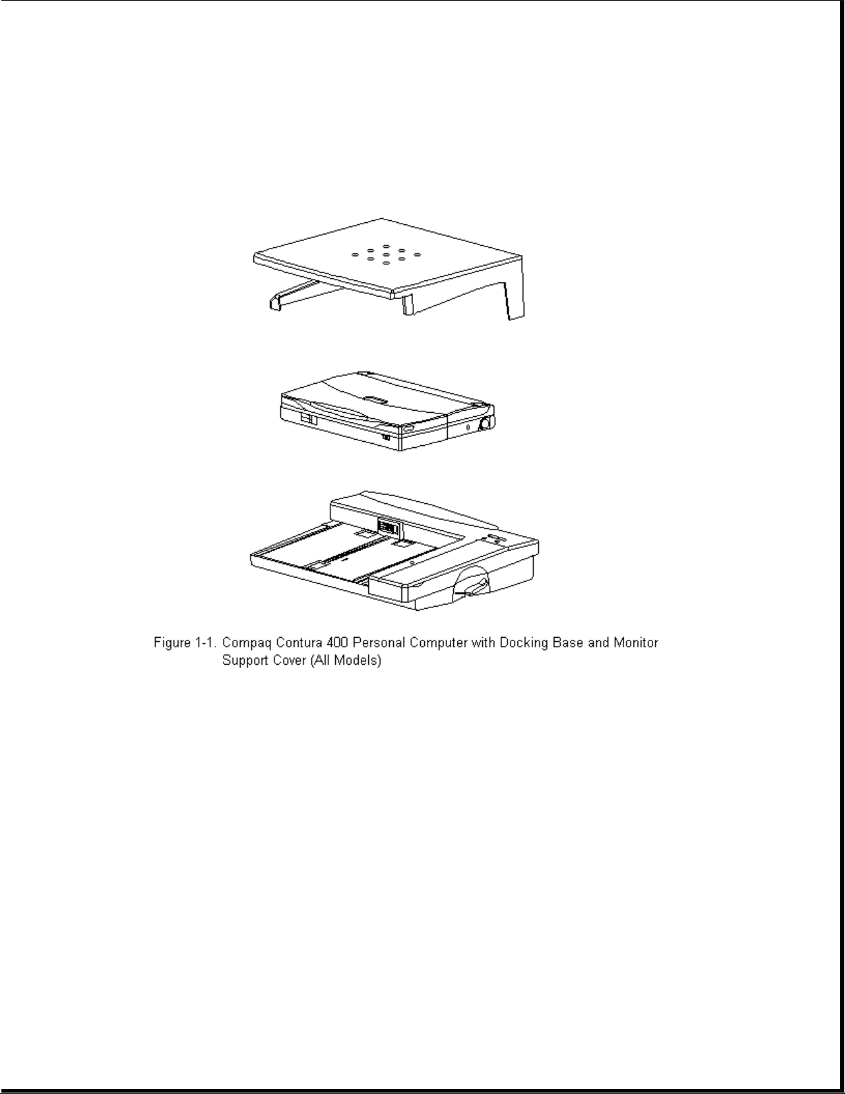
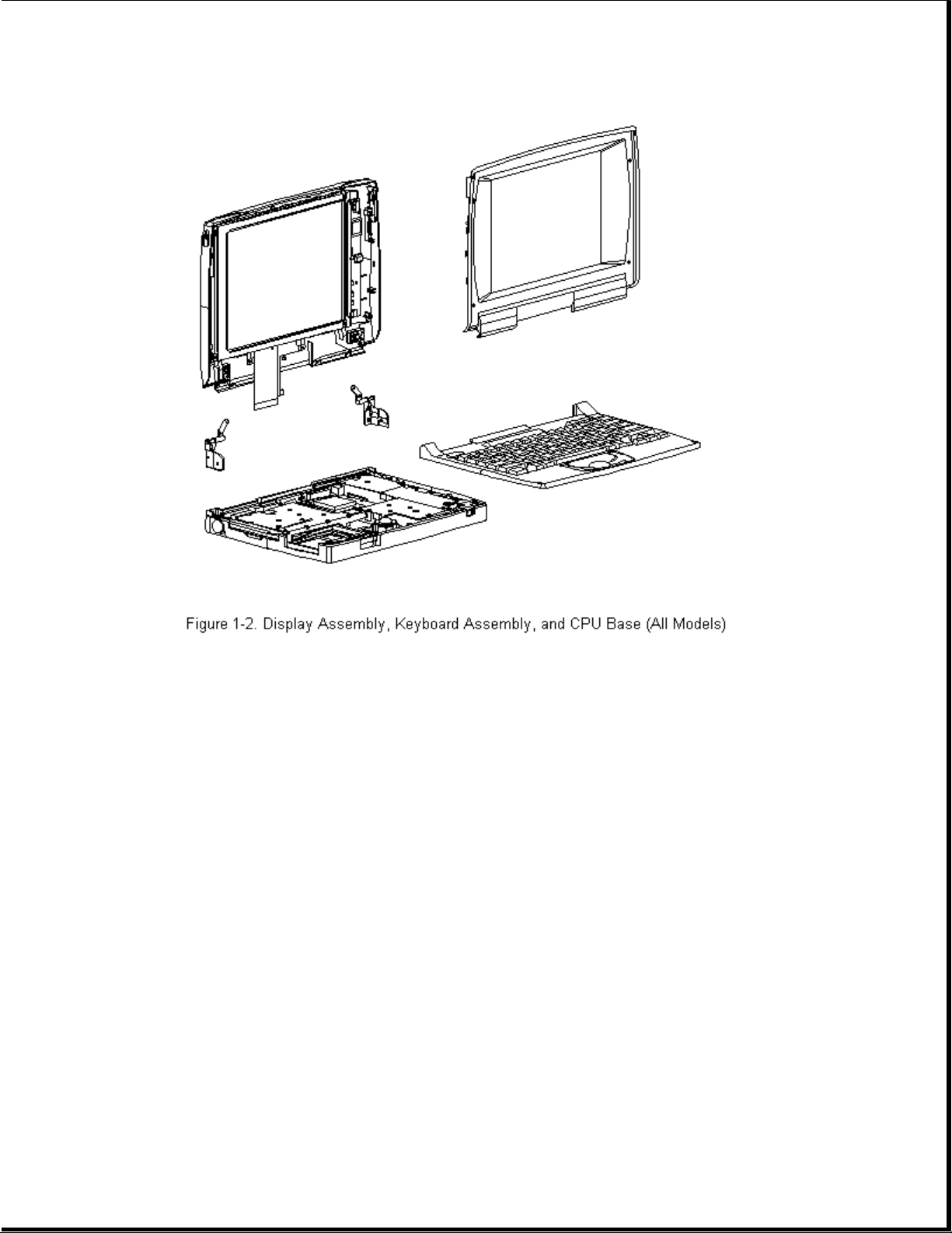
The computer combines a display assembly and system unit module. The
display and system unit module are joined together by clutches on either
side secured by screws in the chassis and display enclosure allowing it to
open and close. The system unit module is secured to the CPU base by screw
locks in the rear and screws in the bottom of the system unit enclosure.
The display assembly is secured by screws installed in the front bezel of
the display enclosure.
This chapter provides a description of the system unit module, display
assembly, docking base, and monitor support cover. It includes a complete
parts breakdown.
Page 6
Chapter 1.2 Serial Number
The computer serial numbers should be provided to Compaq whenever
requesting information or ordering spare parts. The serial number is
located on the bottom of the computer.
The serial number on the Docking Base is located on the rear of the base.
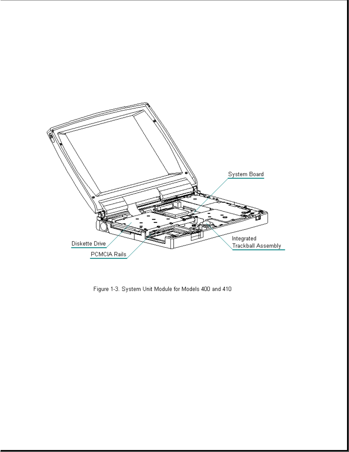
Chapter 1.3 System Unit Module Overview
The system unit module (Figure 1-4) contains the following upgradable
components:
o Hard drive
o Memory expansion board
o Processor upgrade (Contura 400 only)
A complete list of replaceable parts is included in Table 1-1. Major
components include:
Page 7

o Battery pack and compartment components
o Keyboard assembly
o Integrated trackball assembly
o Diskette drive
o System board
o PC Card (PCMCIA) ejector rails and components
The hard drive, memory expansion board, and battery pack are accessed from
the bottom of the computer. To service the remaining system unit module
components, the keyboard assembly must be removed. Most major components
connect directly to the system board by connectors. The only cables in
this unit are the display assembly cable, the display ground cable, and
diskette drive cable.
Compaq Contura Models
Table 1-1 lists the Compaq Contura 400 Family of Personal Computer Models
and standard features.
Table 1-1. Compaq Contura 400 Family of Personal Computer Models
===========================================================================
Model Processor Hard Drive Memory Display
===========================================================================
Contura 400 486 DX2/40 MHz 170 MB 4 MB 9.5 in Monochrome
Contura 400 486 DX2/40 MHz 250 MB 4 MB 9.5 in Monochrome
Contura 400C 486 DX2/40 MHz 250 MB 4 MB 9.5 in Color STN
Contura 400CX 486 DX2/40 MHz 250 MB 4 MB 8.4 in. Color TFT
Contura 410 486 DX2/50 MHz 250 MB 4 MB 9.5 in Monochrome
Contura 410C 486 DX2/50 MHz 250 MB 4 MB 9.5 in Color STN
Contura 410C 486 DX2/50 MHz 350 MB 4 MB 9.5 in Color STN
Contura 410CX 486 DX2/50 MHz 350 MB 4 MB 8.4 in. Color TFT
Contura 420C 486 DX4/75 MHz 350 MB 4 MB 10.4 in. Color STN
Contura 420C 486 DX4/75 MHz 420 MB 8 MB 10.4 in. Color STN
Contura 420CX 486 DX4/75 MHz 420 MB 8 MB 10.4 in. Color TFT
Contura 430C 486 DX4/100 MHz 420 MB 8 MB 10.4 in. Color STN
Contura 430C 486 DX4/100 MHz 720 MB 8 MB 10.4 in. Color STN
Contura 430CX 486 DX4/100 MHz 720 MB 8 MB 10.4 in. Color TFT
--------------------------------------------------------------------------Note: Processor, hard drive and memory upgrades are available for most
models
Page 8

===========================================================================
Models 400 and 410
This section provides a description of the system unit module components
for Models 400 and 410. These components are accessed from the bottom of
the computer:
o Hard drive -- The hard drive is easily replaced or upgraded from the
bottom of the computer. Remove two screws from the hard drive
compartment cover to access the hard drive. The hard drive mounts to the
system chassis with a hard drive bracket and connects directly to the
system board with no intervening cables. The hard drive bracket attaches
to the hard drive with four screws.
o Memory expansion -- System memory can be upgraded with optional memory
expansion boards. An expansion board is added or replaced from the
bottom of the computer through the memory compartment cover. The memory
expansion board connects directly to the system board with two
connectors.
o Battery pack -- The Nickel Metal Hydride battery pack is accessed
through the battery compartment.
To access the remaining system unit components, open the computer and
remove the keyboard assembly. These components include the following:
o Integrated trackball assembly -- The mechanical trackball is centrally
located at the bottom of the keyboard assembly. The assembly consists of
the trackball, retaining ring, and connector. The trackball assembly
connects directly to the system board and is secured by one screw. It
cannot be replaced with the optical trackball used in the Models 420 and
430. The mechanical trackball and optical trackball are not
interchangeable.
o System board -- The system board is mounted directly to the system
chassis. All removable components connected to the system board, except
for the PC Card rails, must be removed prior to removing the system
board. The system board is unique and cannot be replaced by the one
used in the Models 420 and 430.
o Processor upgrade -- Systems that come with the DX2/40 MHz processor can
be upgraded to the DX2/50 MHz processor. Place the upgrade processor into
the two connectors on the system board (Refer to "Removal and
Replacement Procedures, Section 3.11). Once installed, the processor
overrides control of the system board processor. The system board
processor is not removable.
o Real-Time Clock Battery -- This battery is located directly behind the
Trackball.
o PC Card rails -- The PC Card rails are replaceable and are secured by
two screws from the bottom of the system board and a clip on top of the
rails. The rails are not interchangeable with those used in Models 420
and 430. The clip is common between all models. The header attaches
directly to the system board and cannot be removed. The top and bottom
Page 9
PC Card ejection levers are replaceable, but are not interchangeable
with those used in the Models 420 and 430.
o Diskette drive -- The diskette drive attaches to the system board by a
bracket and three screws. It is connected by a diskette drive cable and
LIF connector. The bracket attaches to the drive with four screws. The
drive is protected by an insulator between the system board and the
drive.
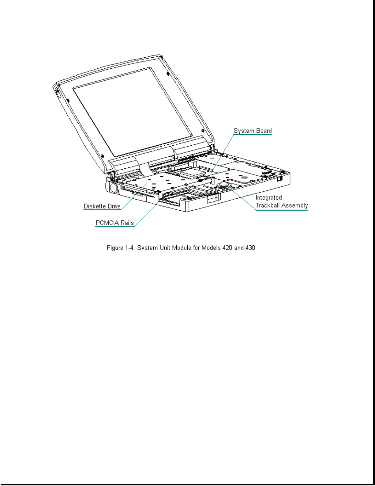
Models 420 and 430
This section provides a description of the system unit module components
for Models 420 and 430. These components are accessed from the bottom of
the computer:
o Hard drive -- The hard drive is easily replaced or upgraded from the
bottom of the computer. Remove two screws from the hard drive
compartment cover to access the hard drive. The hard drive mounts to the
system chassis with a hard drive bracket and connects directly to the
system board with no intervening cables. The hard drive bracket attaches
to the hard drive with four screws.
o Memory expansion -- System memory can be upgraded with optional memory
expansion boards. An expansion board is added or replaced from the
bottom of the computer through the memory compartment cover. The memory
expansion board connects directly to the system board with two connectors.
Page 10

o Battery pack -- The Nickel Metal Hydride battery pack is accessed
through the battery compartment.
To access the remaining system unit components, open the computer and
remove the keyboard assembly. These components include the following:
o Integrated trackball assembly -- This optical trackball is centrally
located at the bottom of the keyboard assembly. The assembly consists of
the trackball, retaining ring, and connector. The trackball assembly
connects directly to the system board and is secured by two screws. It
cannot be replaced with the mechanical trackball used in the Compaq
Models 400 and 410. The optical trackball and mechanical trackball are
not interchangeable among computer models.
o System board -- The system board is mounted directly to the system
chassis. All removable components connected to the system board, except
for the PC Card rails, must be removed prior to removing the system
board. The system board is unique and cannot be replaced by the one
used in the Compaq Models 400 and 410.
o Processor upgrade -- Models 420 and 430 are equipped with either a
DX4/75 MHz or a DX4/100 MHz processor on the system board. There are no
upgrade provisions for these models.
o Real-Time Clock Battery -- This battery is located in the left rear area
of the system board.
o PC Card rails -- The PC Card rails are replaceable and are secured by
two screws from the bottom of the system board and a clip on top of the
rails. The rails are not interchangeable with those used in Models 420
and 430. The clip is common between all models. The header attaches
directly to the system board and cannot be removed. The top and bottom
PC Card ejection levers are replaceable, but are not interchangeable
with those used in the Models 400 and 410.
o Diskette drive -- The diskette drive attaches to the system board by a
bracket and three screws. It is connected by a diskette drive cable and
LIF connector. The bracket attaches to the drive with four screws. The
drive is protected by an insulator between the system board and the
drive.
Page 11
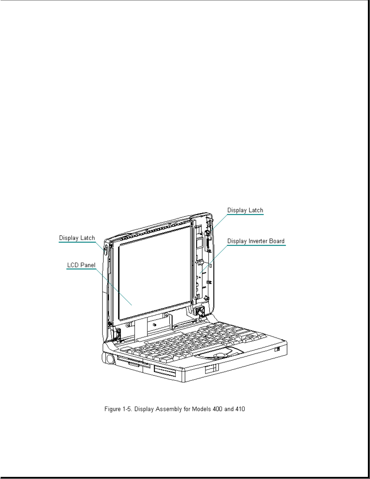
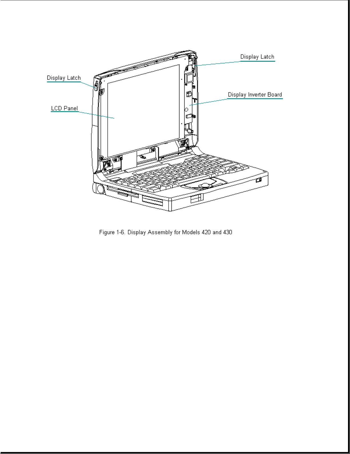
Chapter 1.4 Display Assembly Overview
Display Assembly Description
This section provides a description of the display assembly and
components.
All display assemblies (Figure 1-5 and Figure 1-6) include the following
replaceable parts:
o Bezel
o Enclosure latches
o Inverter board
o Liquid crystal display (LCD) panel
o Shield
o Enclosure
o Display cable and display ground cable
Page 12
To replace the display assembly, the assembly must be removed from the
system unit module. This is done by removing the keyboard assembly,
disconnecting the display cable and display ground cable from the system
unit module, removing the tilt feet and handle brackets, removing the rear
clutch screws, and lifting off the display assembly.
To service display components, do not remove the display assembly from the
system unit module (unless the display enclosure or clutch replacement is
required). Access display components (inverter board or latches) by
removing the bezel secured with four screws on the front of the display.
The display cable is a prefolded, flex cable that connects to the display
inverter board with a low insertion force (LIF) connector. The other end
of the display cable is exposed at the bottom of the display enclosure and
connects to the system board with a zero insertion force (ZIF) slide
connector.
The display ground cable connects to the display shield on one end, and
the other end clips to a LIF-type spring clip located above the serial
port between the system board and system chassis.
The display inverter board is aligned to the right of the display
enclosure with pins. One end connects to the display cable; the other end
connects to the backlight cable of the LCD panel.
Page 13
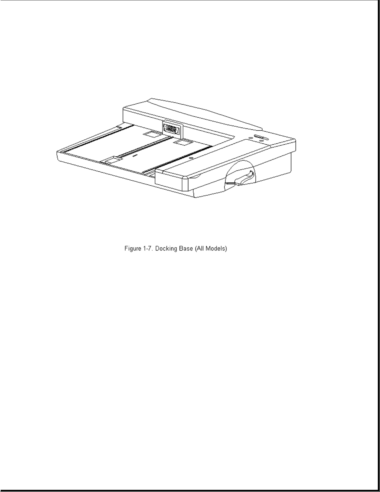
Chapter 1.5 Docking Base
The docking base includes the following replaceable parts:
o Battery door
o Feet
o Handle
Page 14
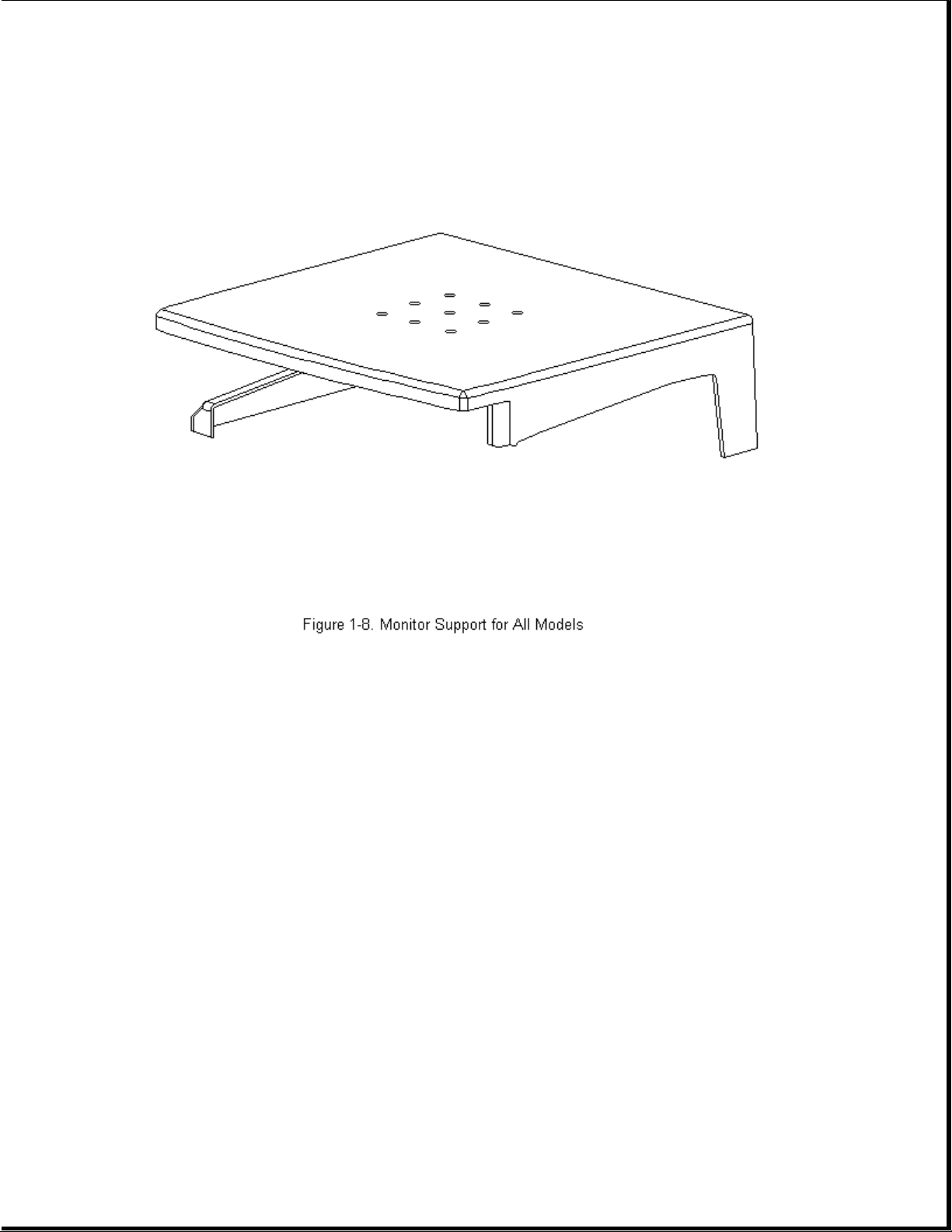
Chapter 1.6 Monitor Support Cover
The monitor support cover is used with the docking base. The foot on the
monitor support cover is the only replaceable part.
Page 15
Chapter 1.7 System Unit Module Parts
Page 16
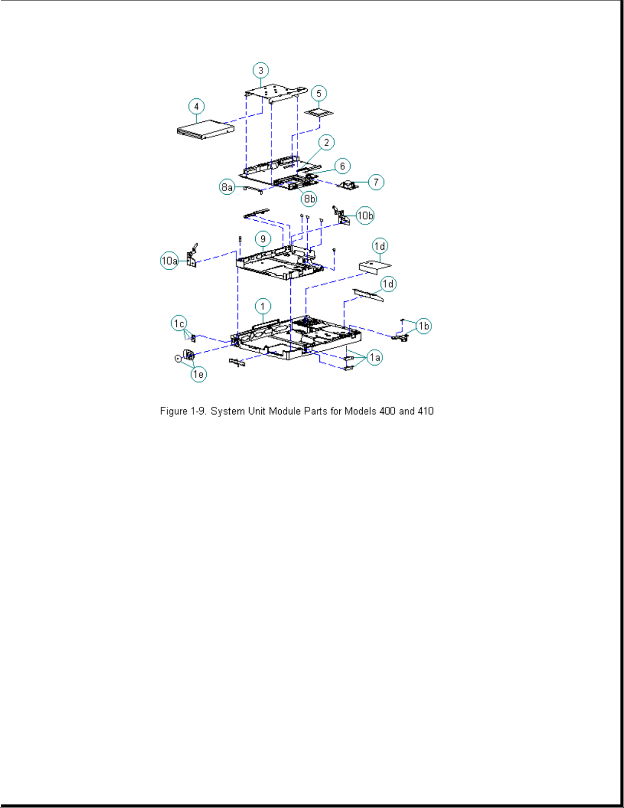
Table 1-2. System Unit Module -- Models 400 and 410
===========================================================================
Spare Part
Description Number Notes
===========================================================================
1. Base enclosure 147856-001 Includes:
a. PC Card eject levers, pin, door,
and spring
b. battery latch button and spring
c. handle bracket, screws and
washers
d. battery shield, insulator
e. tilt foot and screws
f. warning label *
g. anti-skid pads *
h. memory door *
---------------------------------------------------------------------------
2. System board Include PC Card ejector rails, hard
- 486 DX2/40 MHz 147944-001 drive insulators, and gasket.
- 486 DX2/50 MHz 147621-001
---------------------------------------------------------------------------
3. Diskette drive
bracket 147857-001
---------------------------------------------------------------------------
4. Diskette drive 147963-001
---------------------------------------------------------------------------
Page 17

5. Processor upgrade
486 DX2/50 MHz 169644-001
---------------------------------------------------------------------------
6. Real-time clock
battery 117099-001
---------------------------------------------------------------------------
7. Mechanical
Trackball 147876-001
---------------------------------------------------------------------------
8. PC Card ejection Includes the following and screws *.
assembly 147871-001 a. rails
b. clip
c. screws *
---------------------------------------------------------------------------
9. Chassis 147865-001
---------------------------------------------------------------------------
10. Clutches 147858-002 Includes:
a. left
b. right
---------------------------------------------------------------------------
11. Hard drive *
- 350 MB 189111-001 Does not include hard drive bracket.
- 250 MB 199233-001
- 170 MB 169685-001
---------------------------------------------------------------------------
12. Hard drive
bracket * 147872-001
---------------------------------------------------------------------------
13. Memory expansion
board *
- 4 MB 147654-001
- 8 MB 147656-001
- 16 MB 147658-001
- 24 MB 189261-001
---------------------------------------------------------------------------
14. NiMH battery
pack * 190626-001
---------------------------------------------------------------------------
15. Screws kit * 147885-001
---------------------------------------------------------------------------
* Not Shown
===========================================================================
Page 18
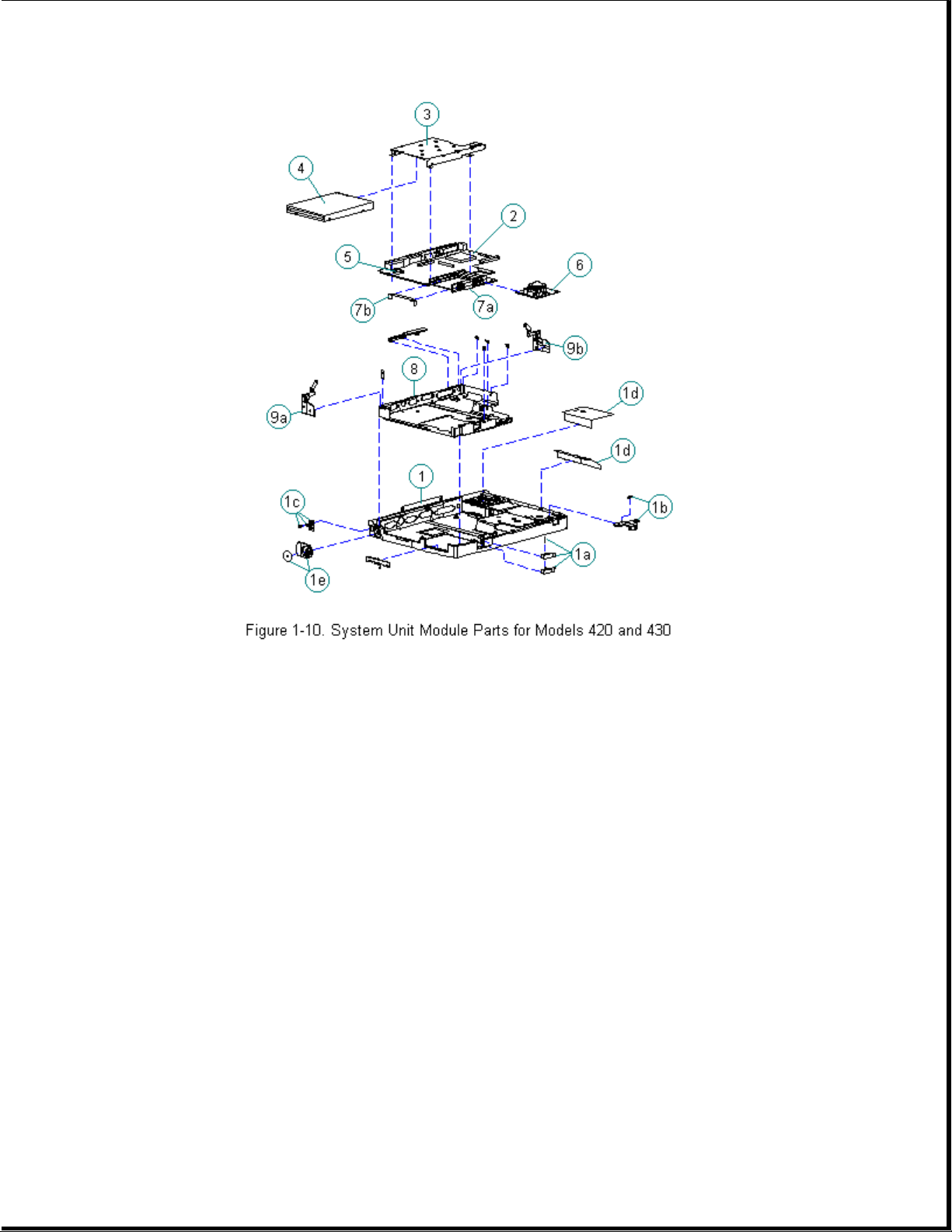
Table 1-3. System Unit Module -- Models 420 and 430
===========================================================================
Spare Part
Description Number Notes
===========================================================================
1. Base enclosure 189239-001 Includes:
a. PC Card eject levers, pin, door,
and spring
b. battery latch button and spring
c. handle bracket, screws and
washers
d. battery shield, insulator
e. tilt foot and screws
f. warning label *
g. anti-skid pads *
h. memory door *
---------------------------------------------------------------------------
2. System board Includes PC Card ejector rails,
- 486 DX4/75 MHz 189115-001 hard drive insulators, and gasket
4MB
- 486 DX4/75 MHz 189116-001
8MB
- 486 DX4/100 MHz 189134-001
8MB
Page 19

---------------------------------------------------------------------------
3. Diskette drive
bracket 189240-001
---------------------------------------------------------------------------
4. Diskette drive 147963-001
---------------------------------------------------------------------------
5. Real-time clock
battery 117099-001
---------------------------------------------------------------------------
6. Optical Trackball
assembly 189197-001
---------------------------------------------------------------------------
7. PC Card ejection Includes the following and screws *.
assembly 189242-001 a. rails
b. clip
c. screws *
---------------------------------------------------------------------------
8. Chassis 189241-001
---------------------------------------------------------------------------
9. Clutches 147858-001 Includes:
a. left
b. right
---------------------------------------------------------------------------
10. Hard drive * Does not include hard drive bracket.
- 720 MB 189156-001
- 540 MB 189132-001
- 420 MB 189112-001
- 350 MB 189111-001
---------------------------------------------------------------------------
11. Hard drive
bracket * 147872-001
---------------------------------------------------------------------------
12. Memory expansion
board *
- 4 MB 147654-001
- 8 MB 147656-001
- 16 MB 147658-001
- 24 MB 189261-001
---------------------------------------------------------------------------
13. NiMH battery
pack * 190626-001
---------------------------------------------------------------------------
14. Screws kit * 147885-001
---------------------------------------------------------------------------
* Not Shown
===========================================================================
Chapter 1.8 Monochrome Display Assembly Parts
Page 20
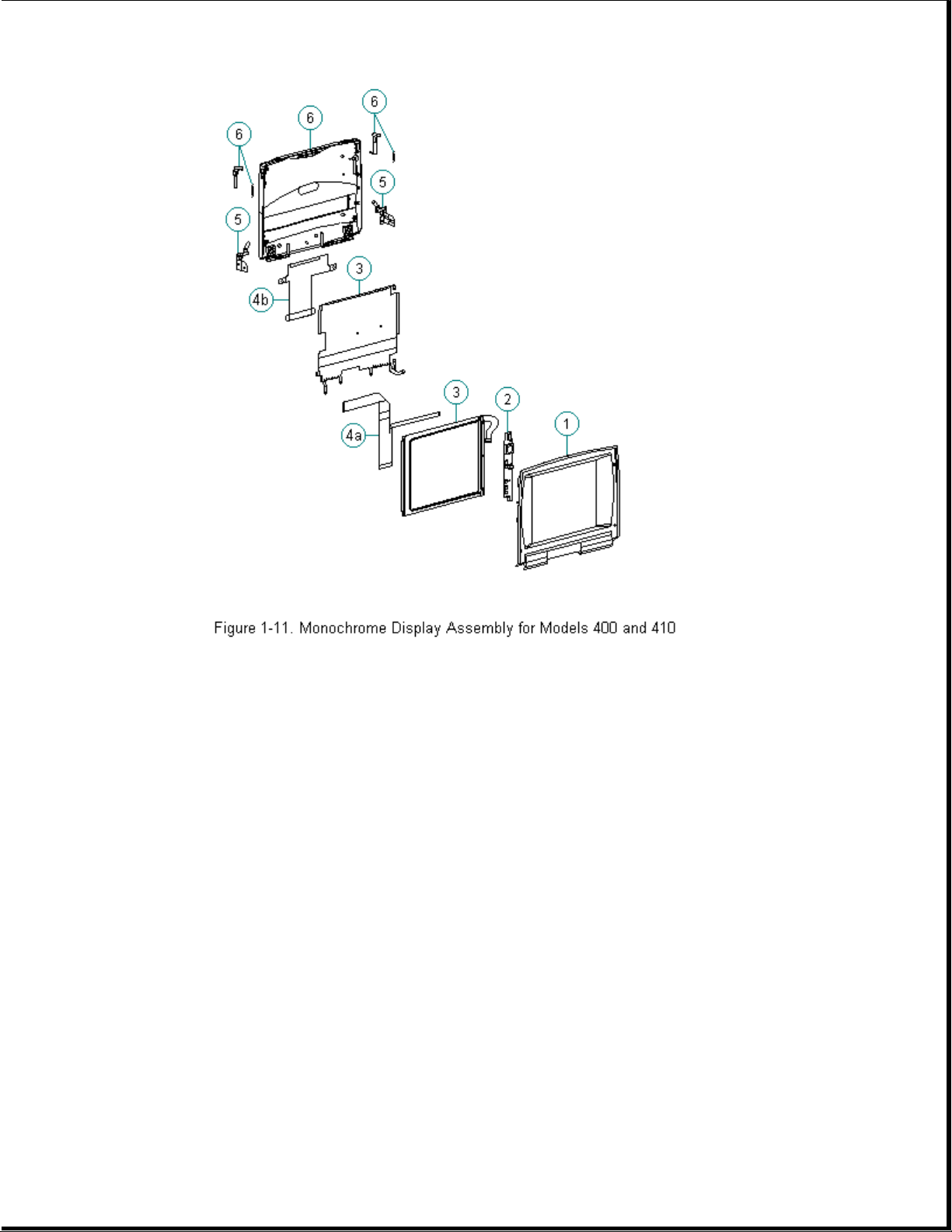
Table 1-4. Monochrome Display Assembly -- Models 400 and 410
===========================================================================
Description Spare Part Number Notes
===========================================================================
1. Display bezel 147882-001
2. Backlight inverter
board 147622-001
3. Display panel 147877-001 Includes labels and shield
4. Display cables 147884-001 Includes:
a. display cable
b. display ground cable
5. Display clutch 147858-001 Includes screws for handle
(left and right) bracket, washer, tilt feet
6. Display enclosure 147880-001 Includes enclosure, latch,
kit spring, and logo
7. Screw kit * 147885-001
---------------------------------------------------------------------------
* Not Shown
===========================================================================
Page 21
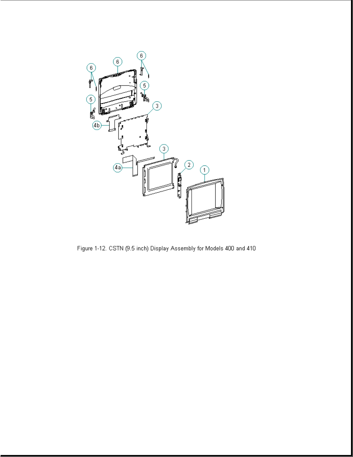
Chapter 1.9 Color STN (9.5 inch) Display Assembly Parts
Table 1-5. CSTN (9.5 inch) Display Assembly -- Models 400 and 410
===========================================================================
Description Spare Part Number Notes
===========================================================================
1. Display bezel 147883-001
2. Backlight inverter
board 147624-001
3. Display panel 147878-001 Includes labels and shield
4. Display cables 147884-001 Includes:
a. display cable
b. display ground cable
5. Display clutch 147858-001 Includes screws for handle
(left and right) bracket, washer, tilt feet
6. Display enclosure 147881-001 Includes enclosure, latch,
kit spring, and logo
7. Screw kit * 147885-001
---------------------------------------------------------------------------
* Not Shown
Page 22
===========================================================================
Chapter 1.10 Color STN (10.4 inch) Display Assembly Parts
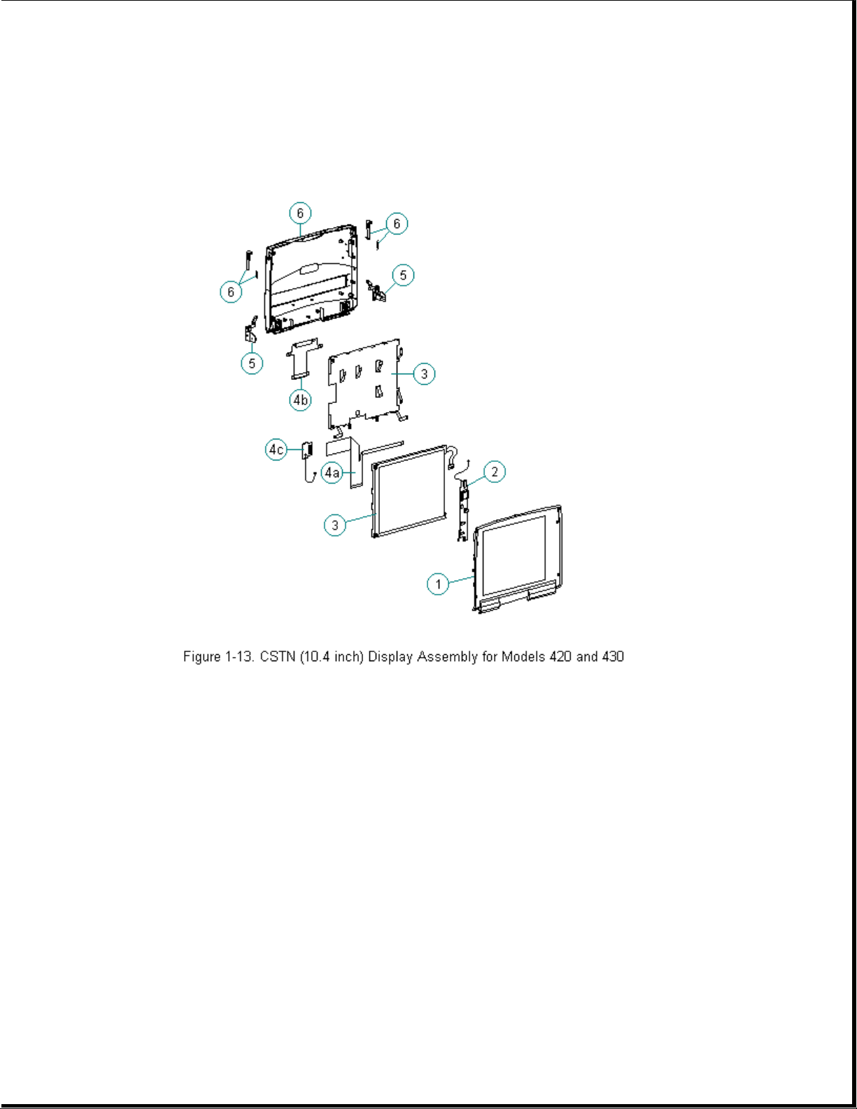
Table 1-6. CSTN (10.4 inch) Display Assembly -- Models 420 and 430
===========================================================================
Spare Part
Description Number Notes
===========================================================================
1. Display bezel 189246-001
2. Backlight inverter
board 189135-001
3. Display panel 189113-001 Includes labels and shield
4. Display cables 189247-001 Includes:
a. display cable
b. display ground cable
c. XOVER board
5. Display clutch Includes screws for handle
(left and right) 147858-001 bracket, washer, tilt feet
Page 23
6. Display enclosure Includes enclosure, latch,
kit 189245-001 spring, logo and pad for
Sharp CSTN
7. Screw kit * 147885-001
--------------------------------------------------------------------------* Not Shown
===========================================================================
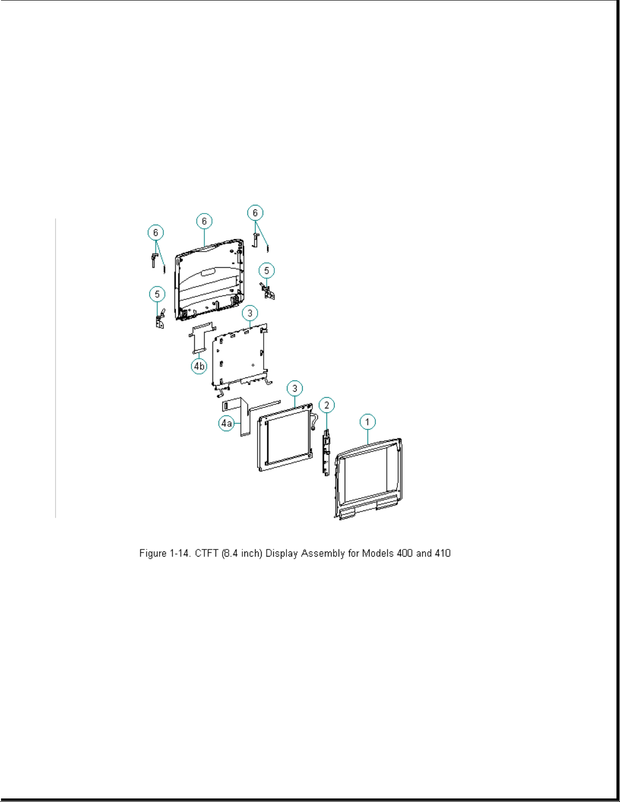
Chapter 1.11 Color TFT (8.4 inch) Display Assembly Parts
Table 1-7. CTFT (8.4 inch) Display Assembly -- Models 400 and 410
===========================================================================
Spare Part
Description Number Notes
===========================================================================
1. Display bezel 147869-001
2. Backlight inverter
board 147624-001
3. Display panel 147879-001 Includes labels and shield
4. Display cables 147884-001 Includes:
Page 24
a. display cable
b. display ground cable
5. Display clutch Includes screws for handle
(left and right) 147858-001 bracket, washer, tilt feet
6. Display enclosure Includes enclosure, latch,
kit 147881-001 spring, and logo
7. Screw kit * 147885-001
--------------------------------------------------------------------------* Not Shown
===========================================================================
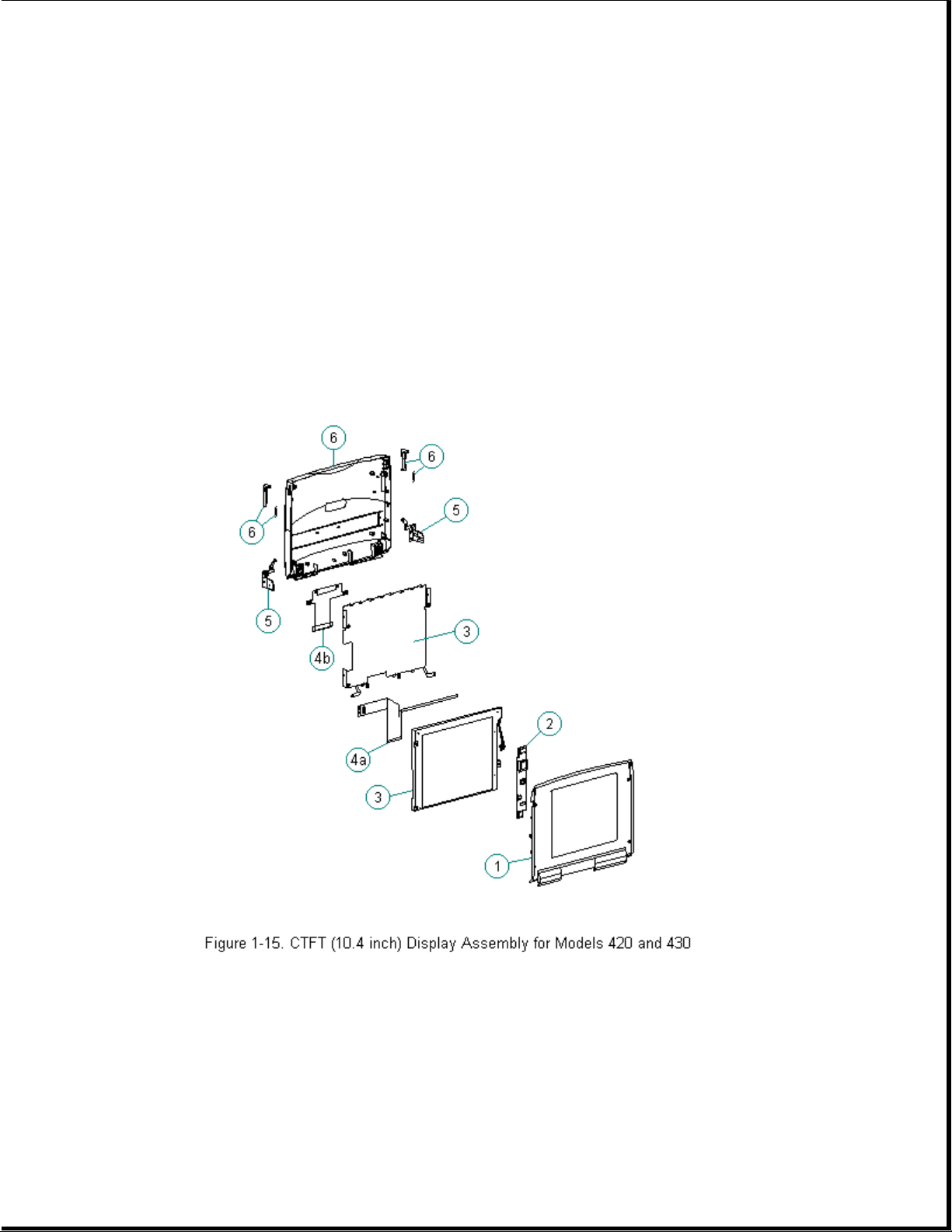
Chapter 1.12 Color TFT (10.4 inch) Display Assembly Parts
Table 1-8. CTFT (10.4 inch) Display Assembly -- Models 420 and 430
===========================================================================
Spare Part
Description Number Notes
===========================================================================
1. Display bezel 189244-001
2. Backlight inverter
Page 25
board 189136-001
3. Display panel 189114-001 Includes labels and shield
4. Display cables 189247-001 Includes:
a. display cable
b. display ground cable
5. Display clutch Includes screws for handle
(left and right) 147858-001 bracket, washer, tilt feet
6. Display enclosure Includes enclosure, latch,
kit 189243-001 spring, and logo.
7. Screw kit * 147885-001
--------------------------------------------------------------------------* Not Shown
===========================================================================
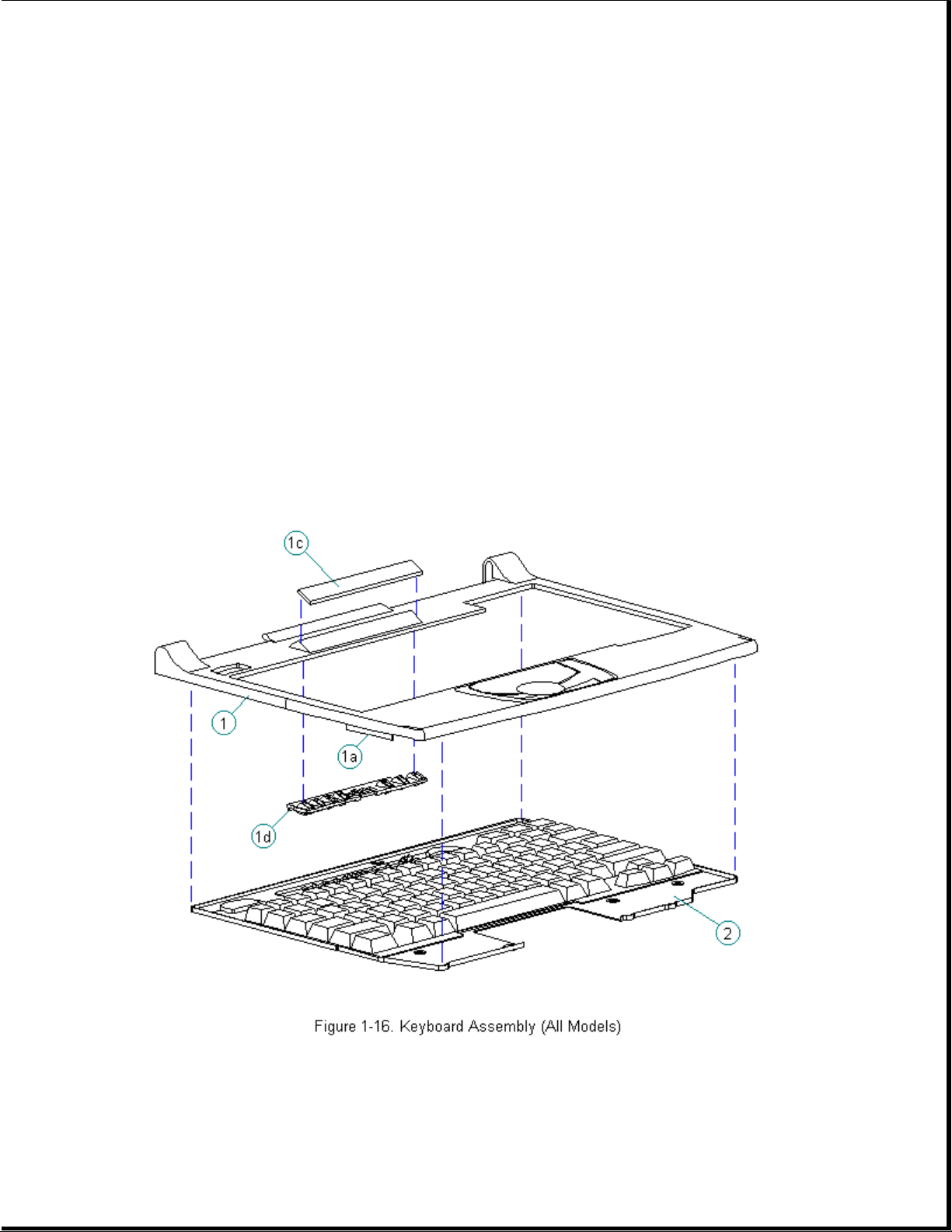
Chapter 1.13 Keyboards
Table 1-9. Contura Notebook Keyboards
===========================================================================
Description Spare Part Number
Page 26

===========================================================================
1. CPU Cover Includes: 147860-001
a. PC Card door
b. spring *
c. indicator panel
d. light deflector
2. U.S. 147875-001
3. U.K. 147875-003 *
4. German 147875-004 *
5. French 147875-005 *
6. Italian 147875-006 *
7. Spanish 147875-007 *
8. Danish 147875-008 *
9. Norwegian 147875-009 *
10. Swedish/Finnish 147875-010 *
11. Swiss 147875-011 *
12. French Canadian 147875-012 *
13. Portuguese 147875-013 *
14. Latin American 147875-016 *
15. Belgian 147875-018 *
16. Japanese 147875-019 *
17. Korean 147875-033 *
18. Brazilian 147875-035 *
--------------------------------------------------------------------------* Not Shown
===========================================================================
Page 27
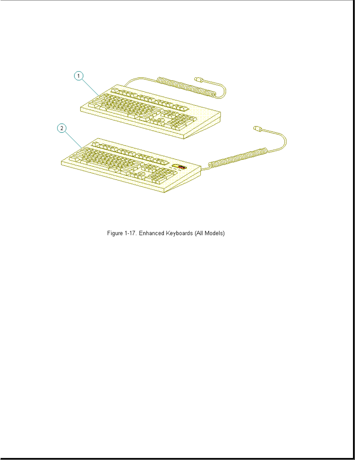
Table 1-10. Contura Enhanced Keyboards
===========================================================================
Description Spare Part Number
===========================================================================
1. Enhanced II Keyboard - Domestic 140536-101
2. Enhanced III Keyboard - U.K. 140536-103
3. Enhanced III Keyboard - German 140536-104 *
4. Enhanced III Keyboard - French 140536-105 *
5. Enhanced III Keyboard - Italian 140536-106 *
6. Enhanced III Keyboard - Spanish 140536-107 *
7. Enhanced III Keyboard - Danish 140536-108 *
8. Enhanced III Keyboard - Norwegian 140536-109 *
9. Enhanced III Keyboard - Swedish/Finnish 140536-110 *
10. Enhanced III Keyboard - Swiss 140536-111 *
11. Enhanced III Keyboard - French Canadian 140536-112 *
Page 28

12. Enhanced III Keyboard - Portuguese 140536-113 *
)
13. Enhanced III Keyboard - Turkish 140536-114 *
14. Enhanced III Keyboard - Greek 140536-115 *
15. Enhanced III Keyboard - Latin American 140536-116 *
16. Enhanced III Keyboard - Arabic 140536-117 *
17. Enhanced III Keyboard - Belgian 140536-118 *
18. Enhanced III Keyboard - Japanese 140536-119 *
19. Enhanced III Keyboard - BHCSY ** 140536-120 *
20. Enhanced III Keyboard - Hungarian 140536-121 *
21. Enhanced III Keyboard - Polish 140536-122 *
22. Enhanced III Keyboard - Slovakian 140536-123 *
23. Enhanced III Keyboard - Russian 140536-124 *
24. Enhanced III Keyboard - Czech 140536-129 *
25. Enhanced III Keyboard - Thai 140536-130 *
26. Enhanced III Keyboard - Beijing 140536-132 *
27. Enhanced III Keyboard - Segul 140536-133 *
28. Enhanced III Keyboard - Taipei 140536-134 *
29. Enhanced III Keyboard - Brazil 140536-135 *
--------------------------------------------------------------------------* Not Shown
** Bosnia-Herzegovina, Croatia, Slovenia, and Yugoslavia
===========================================================================
Chapter 1.14 Cables (Models 400 and 410
Page 29
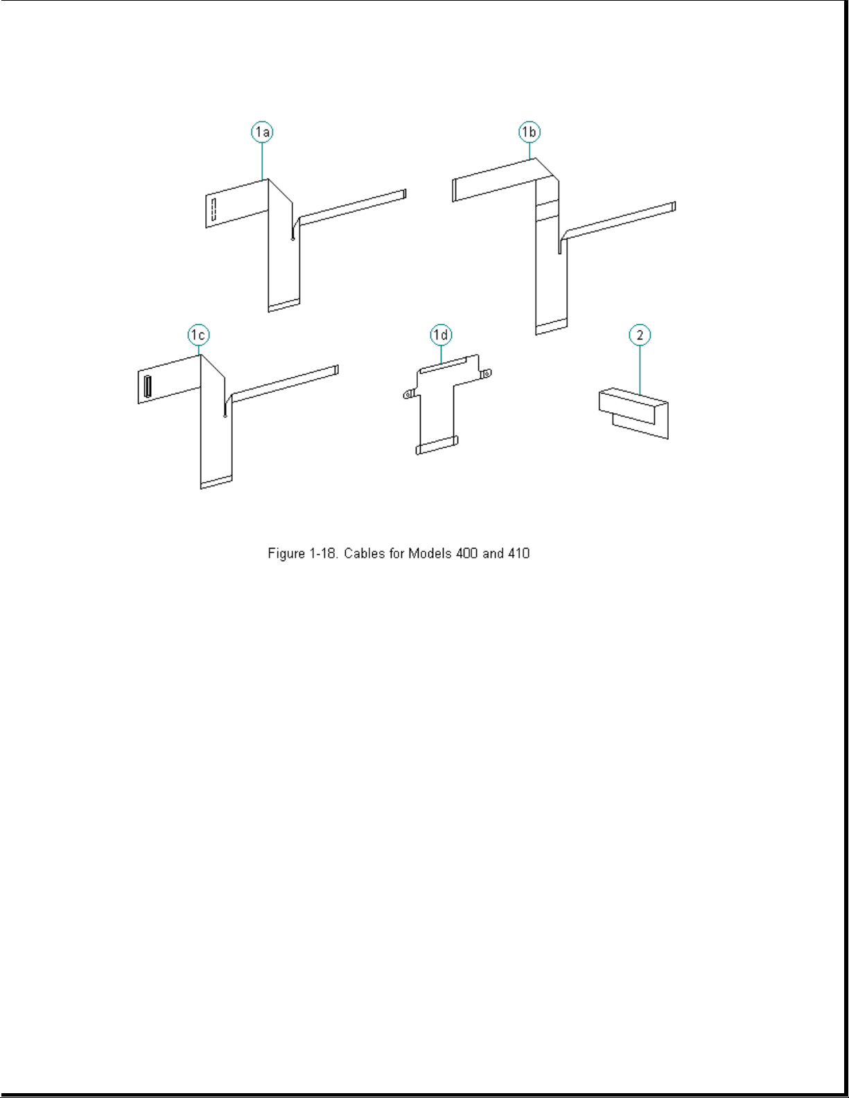
Table 1-11. Cables for Models 400 and 410
)
===========================================================================
Description Spare Part Number
===========================================================================
1. Display cables 147884-001
a. CSTN (9.5 in) Models 400 and 410
b. MSTN (9.5 in) (Model 400 only)
c. CTFT (8.4 in) Models 400 and 410
d. Ground cable for Models 400 and 410
---------------------------------------------------------------------------
2. Diskette cable 147866-001
===========================================================================
Chapter 1.15 Cables (Models 420 and 430
Page 30
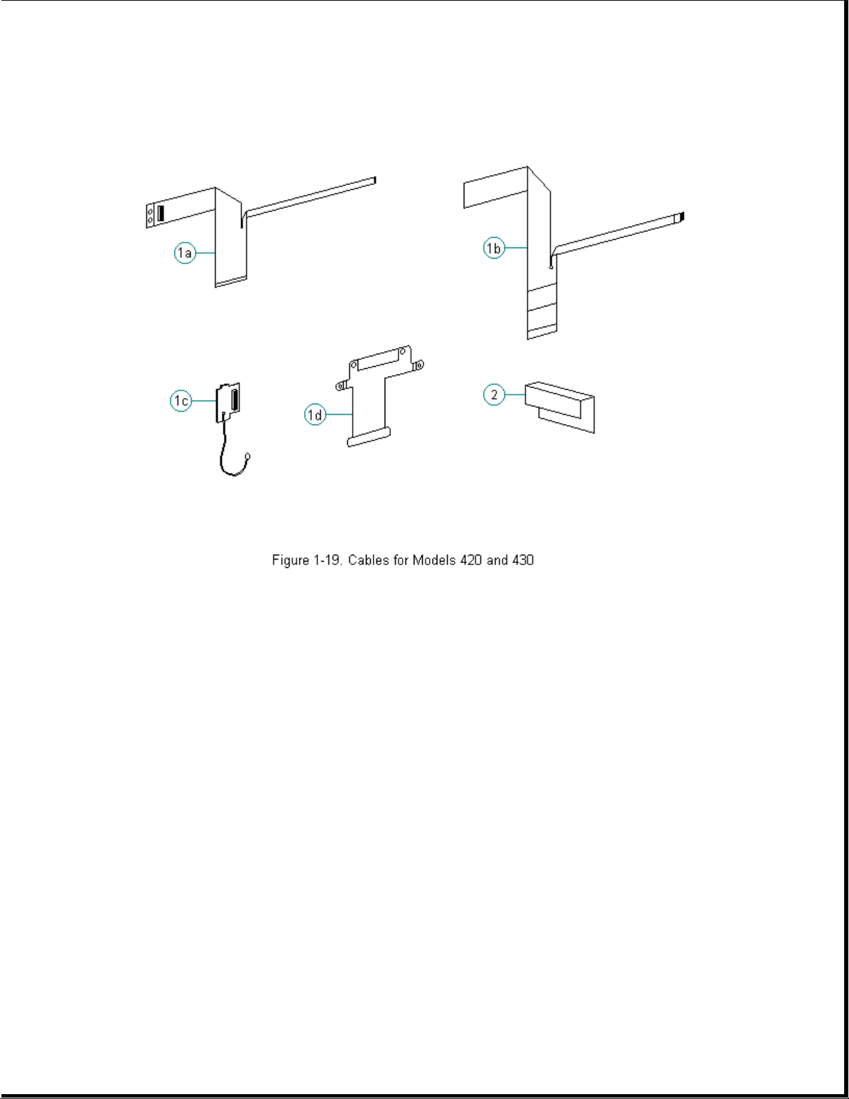
Table 1-12. Cables for Models 420 and 430
===========================================================================
Description Spare Part Number
===========================================================================
1. Display cables 189247-001
a. CTFT (10.4 in) Models 420 and 430
b. CSTN (10.4 in) Models 420 and 430
c. XOVER board for CSTN (10.4 in) only
d. Ground cable for Models 420 and 430
---------------------------------------------------------------------------
2. Diskette cable 147866-001
===========================================================================
Chapter 1.16 Ac Adapter and Power Cord
Page 31

Table 1-13. Contura AC Adapter and Power Cord
===========================================================================
Description (All Models) Spare Part Numbers
===========================================================================
1. AC adapter with wallprongs 147679-001
2. AC adapter 147679-002
3. Power cord (U.S./Canada) 197230-001
4. Power cord (U.K.) 197232-001 *
5. Power cord (Europe) 197231-001 *
6. Power cord (Japan) 197233-001 *
7. Power cord (Australia) 197234-001 *
---------------------------------------------------------------------------
* Not shown
===========================================================================
Chapter 1.17 Memory and Processor
Page 32

Table 1-14. Contura Memory and Processor
===========================================================================
Description (All Models) Spare Part Numbers
===========================================================================
1. Memory expansion board
a. 4 MB 147654-001
b. 8 MB 147656-001
c. 16 MB 147658-001
d. 24 MB * 189261-001
2. Processor upgrade (Model 400 only)
486 DX2/50 MHz 169644-001
---------------------------------------------------------------------------
* Not Shown
===========================================================================
Chapter 1.18 Miscellaneous Carrying Devices
Page 33
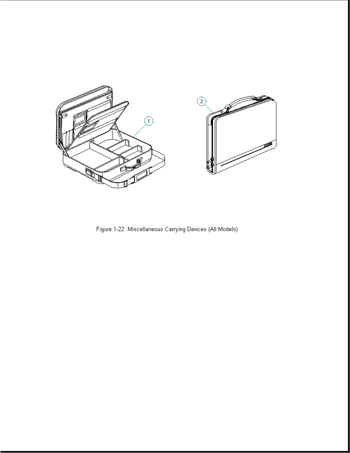
Table 1-15. Miscellaneous Carrying Devices
===========================================================================
Description (All Models) Spare Part Numbers
===========================================================================
1. Briefcase, Ramie 129930-001
2. Slipcase 194162-001
3. Briefcase, SS (soft-sided) 121423-001 *
---------------------------------------------------------------------------
* Not Shown
===========================================================================
Chapter 1.19 Docking Base and Monitor Support Cover
Page 34
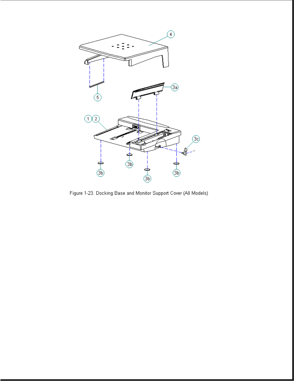
Table 1-16. Docking Base and Monitor Support Cover
===========================================================================
Description (All Models) Spare Part Numbers
===========================================================================
1. Docking Base - Ethernet 147675-001
2. Docking Base - pass-thru 147699-001
3. Docking base miscellaneous 169666-001
a. Battery door
b. Feet
c. Handle
d. Screws (Quantity = 2)
4. Monitor support cover 147676-001
5. Monitor support cover foot 169681-001
---------------------------------------------------------------------------
* Not Shown
===========================================================================
Chapter 1.20 Miscellaneous CPU Kits
Table 1-17. Miscellaneous Contura CPU Kits
Page 35

===========================================================================
Description Spare Part Number Spare Part Number
Models 400 & 410 Models 420 & 430
===========================================================================
Handle 147678-001 * 147678-001 *
--------------------------------------------------------------------------Automobile adapter 190551-002 * 190551-002 *
--------------------------------------------------------------------------Memory door assembly
includes hard drive tray 169713-001 * 169713-001
--------------------------------------------------------------------------Carton, (Quantity = 5) 147862-001 * 147862-001 *
--------------------------------------------------------------------------Carton and buns, (Quantity = 1) 147863-001 * 147863-001 *
--------------------------------------------------------------------------Clutches (left and right) 147858-001 * 147858-001 *
--------------------------------------------------------------------------Anti-skid feet 147859-001 * 147859-001 *
--------------------------------------------------------------------------Plate logo 197251-001 * 189292-001 *
--------------------------------------------------------------------------Box, 420C 189265-001 *
--------------------------------------------------------------------------SpeedPaq 192 Data Fax Cellular 187123-001
Modem
--------------------------------------------------------------------------PC Card (PCMCIA) 288 Fax/Modem 189661-001 *
--------------------------------------------------------------------------PC Card (PCMCIA) 192 Fax/Modem 188512-001 *
--------------------------------------------------------------------------PC Card (PCMCIA) modem pouch 194133-001 *
--------------------------------------------------------------------------CA, TEL MED 187145-001 *
--------------------------------------------------------------------------Keyboard Warning Label, English 189288-001 *
--------------------------------------------------------------------------Country Kit 140204-001 *
--------------------------------------------------------------------------Trackball removal tool 147779-001 * 147779-001 *
--------------------------------------------------------------------------Miscellaneous 147874-001 * 189262-001 *
Includes:
Trough
Battery latch
Battery tray
PC Card door
PC Card ejection levers and pin
Extension spring (battery eject button,
display latches)
Lock plate provision
Keyboard ground clips
Left clutch ground clip
Right clutch ground clip
Flex ground clip
Hard Drive Tray
--------------------------------------------------------------------------* Not Shown
===========================================================================
Page 36

Chapter 1.21 Fastener List
Table 1-18. Fastener Kit for All Models
===========================================================================
Description: Spare Part Number
--------------------------------------------------------------------------Screws and Fastners Kit (Quantity = 25 each) 147885-001
===========================================================================
===========================================================================
Description Type Where Used Part Number Drive Qty
===========================================================================
M2.5 x 4.0 Truss Ground tabs on 144864-001 SL/T8 3 *
display shields
Diskette bracket 3
to system board
Hold down system 5 *
board to base and 4 **
chassis
Trackball assembly 1 *
to base 2 **
Battery contracts 2
to base/through
system board
CPU cover to 7
keyboard
Clutches to 4 *
display enclosure
(Models 400 and
410)
--------------------------------------------------------------------------M2.5 x 5.0 Truss CPU base to 144865-007 SL/T8 4
clutches Blk 4
Display bezel to
display enclosure
Ground tabs on 2 **
display shields
(Models 420 and
430)
Clutches to 4 **
display enclosure
(Models 420 and
430)
Display to display
enclosure 4 **
--------------------------------------------------------------------------Description Type Where Used Part Number Drive Qty
---------------------------------------------------------------------------
Page 37

M3.0 x 8.0 Pan Display to display 121187-007 SL/T8 4 **
enclosure
--------------------------------------------------------------------------M2.5 x 24.0 Truss CPU cover to CPU 144865-006 SL/T8 7
base
--------------------------------------------------------------------------M2.6 x 2.0 Fillister Diskette drive 121188-001 T8 4
to FDD bracket
--------------------------------------------------------------------------M3.0 x 3.6 Truss Hard drive to HDD 121187-001 T8 4
bracket
--------------------------------------------------------------------------M2.0 x 6.0 Fillister PC Card Header 126790-004 T8 2 **
--------------------------------------------------------------------------M2.0 x 15.5 Fillister PCMCIA rails 126790-010 T8 2
--------------------------------------------------------------------------Spring, PC Card door 147758-001 2
torsion actuation
--------------------------------------------------------------------------Spring, Battery latch 147759-001 1
extension return spring
Display latch 2
return spring
--------------------------------------------------------------------------Washer Under handle 147923-001 2
bracket
--------------------------------------------------------------------------M2.5 Shoulder Handle bracket to 147760-001 T8 2
clutch/through CPU
base
--------------------------------------------------------------------------M2.5 Shoulder CPU foot to 147778-001 T8 2
clutch/through CPU
base
--------------------------------------------------------------------------4-40 Screw Three connectors 106902-001 3/16 6
locks at rear of unit
--------------------------------------------------------------------------Alignment Shoulder Alignment screws 169643-001 T8 2
screws for docking base
connector
--------------------------------------------------------------------------* Models 400 and 410
** Models 420 and 430
===========================================================================
Chapter 1.22 Documentation and Software
Table 1-19. Documentation and Software
===========================================================================
Description (All Models) Spare Part Number
===========================================================================
MAINTENANCE AND SERVICE GUIDE 147861-001
---------------------------------------------------------------------------
Online USER'S GUIDE
English 147990-001
Page 38

German 147990-041
French 147990-051
Italian 147990-061
Spanish 147990-071
Netherlands 147990-331
Swedish 147990-101
---------------------------------------------------------------------------
Manuals - English 147989-001
QUICK SETUP
BEYOND SETUP
---------------------------------------------------------------------------
Manuals - German 147989-041
QUICK SETUP
BEYOND SETUP
KEYBOARD REFERENCE
---------------------------------------------------------------------------
Manuals - French 147989-051
QUICK SETUP
BEYOND SETUP
KEYBOARD REFERENCE
---------------------------------------------------------------------------
Manuals - Italian 147989-061
QUICK SETUP
BEYOND SETUP
KEYBOARD REFERENCE
---------------------------------------------------------------------------
Manuals - Spanish 147989-071
QUICK SETUP
BEYOND SETUP
KEYBOARD REFERENCE
---------------------------------------------------------------------------
Manual - TABWORKS QUICK START GUIDE
English 195866-001
German 195866-041
French 195866-051
Italian 195866-061
Spanish 195866-071
Swedish 195866-101
Netherlands 195866-331
---------------------------------------------------------------------------
Manual - AMERICA ONLINE 181194-001
---------------------------------------------------------------------------
Manual - MS WORKS 196077-001
---------------------------------------------------------------------------
Manual - ESSENTIALS OF MS-DOS AND MS-WINDOWS
English 144958-001
German 144958-041
French 144958-051
Italian 144958-061
Spanish 144958-071
Swedish 144958-101
Portuguese 144958-131
Dutch 144958-331
---------------------------------------------------------------------------
Manual - MS-DOS GUIDE, 6.0 and MS Windows
English 195973-001
German 195973-041
French 195973-051
Italian 195973-061
Spanish 195973-071
Page 39

Danish 195973-081
Norwegian 195973-091
Swedish 195973-101
Portuguese 195973-131
Dutch 195973-331
Finnish 195973-351
---------------------------------------------------------------------------
Manual - LOTUS ORGANIZER
English 137885-001
German 137885-041
French 137885-051
Italian 137885-061
Spanish 137885-071
Danish 137885-081
Norwegian 137885-091
Swedish 137885-101
Dutch 137885-331
Finnish 137885-351
---------------------------------------------------------------------------
COMPAQ SERVICE QUICK REFERENCE GUIDE 106854-001
---------------------------------------------------------------------------
ROMPaq diskette 181088-001
===========================================================================
Page 40

Chapter 2. Preparing the Computer for Service
Introduction
This chapter provides general service information necessary to prepare the
computer for service in the following areas:
o Electrostatic discharge
o Service preliminaries
o Battery disposal
Adherence to the procedures and precautions described in this chapter is
essential for proper service.
Chapter 2.1 Electrostatic Discharge
>>>>>>>>>>>>>>>>>>>>>>>>>>>>>>>>> CAUTION <<<<<<<<<<<<<<<<<<<<<<<<<<<<<<<<<
Static electricity can damage electronic components. Before beginning
these procedures, make sure you are grounded (discharged of static
electricity) by briefly touching a grounded, unpainted, metal object or
surface.
>>>>>>>>>>>>>>>>>>>>>>>>>>>>>>>>>>>>><<<<<<<<<<<<<<<<<<<<<<<<<<<<<<<<<<<<<<
A sudden discharge of static electricity from a finger or other conductor
can destroy static-sensitive devices or micro circuitry. Often the spark
is neither felt nor heard, but damage occurs. An electronic device exposed
to electrostatic discharge (ESD) may not be affected at all and will work
perfectly throughout a normal cycle. Or it may function normally for a
while, then degrade in the internal layers, reducing its life expectancy.
Networks built into many integrated circuits provide some protection, but
in many cases, the discharge contains enough power to alter device
parameters or melt silicon junctions.
This section details methods of generating, preventing, and grounding
static electricity.
Generating Static
Table 2-1 shows how different activities generate static electricity and
at different electrostatic voltage levels.
Table 2-1. Typical Electrostatic Voltages
===========================================================================
Relative Humidity
Event 10% 40% 55%
===========================================================================
Walking across carpet 35,000 V 15,000 V 7,500 V
Walking across vinyl floor 12,000 V 5,000 V 3,000 V
Page 41

Motions of bench worker 6,000 V 800 V 400 V
Removing DIPS from plastic tubes 2,000 V 700 V 400 V
Removing DIPS from vinyl trays 11,500 V 4,000 V 2,000 V
Removing DIPS from Styrofoam 14,500 V 5,000 V 3,500 V
Removing bubble pack from PCBs 26,000 V 20,000 V 7,000 V
Packing PCBs in foam-lined box 21,000 V 11,000 V 5,000 V
--------------------------------------------------------------------------NOTE: 700 volts can degrade a product.
===========================================================================
Preventing Electrostatic Damage to Equipment
Many electronic components are sensitive to ESD. Circuitry design and
structure determine the degree of sensitivity. The following proper
packaging and grounding precautions are necessary to prevent damage:
o Protect all electrostatic parts and assemblies with conductive or
approved containers or packaging.
o Keep electrostatic sensitive parts in their containers until they arrive
at static-free stations.
o Place items on a grounded surface before removing them from their
container.
o Always be properly grounded when touching a sensitive component or
assembly.
o Place reusable electronic-sensitive parts from assemblies in protective
packaging or conductive foam.
Use transporters and conveyors made of anti-static belts and metal roller
bushings. Mechanized equipment used for moving materials must be wired to
ground and proper materials selected to avoid static charging. When
grounding is not possible, use an ionizer to dissipate electric charges.
Preventing Damage to Drives
To prevent static damage to hard drives, use the following precautions:
o Handle drives gently, using static-guarding techniques.
o Store drives in the original shipping containers.
o Avoid dropping drives from any height onto any surface.
o Handle drives on surfaces that have at least one inch of shock proof
foam.
o Always place drives PCB assembly side down on the foam.
Page 42

Grounding Methods
The method for grounding must include a wrist strap or a foot strap at a
grounded workstation. When seated, wear a wrist strap connected to a
grounded system. When standing, use footstraps and a grounded floor mat.
Table 2-2. Static-Shielding Protection Levels
===========================================================================
Method Voltages
===========================================================================
Anti-static Plastic 1,500
Carbon-Loaded Plastic 7,500
Metallized Laminate 15,000
===========================================================================
Grounding Workstations
To prevent static damage at the workstation, follow these precautions:
o Cover the workstation with approved static-dissipative material.
Provide a wrist strap connected to the work surface and properly
grounded tools and equipment.
o Use static-dissipative mats, heel straps, or air ionizers to give added
protection.
o Handle electrostatic sensitive components, parts, and assemblies by the
case or PCB laminate. Handle them only at static-free workstations.
o Avoid contact with pins, leads, or circuitry.
o Turn off power and input signals before inserting and removing
connectors or test equipment.
o Use fixtures made of static-safe materials when fixtures must directly
contact dissipative surfaces.
o Keep work area free of nonconductive materials such as ordinary plastic
assembly aids and Styrofoam.
Grounding Equipment
Use the following equipment to prevent static electricity damage to the
equipment:
Wrist Straps are flexible straps with a minimum of 1 megohm +/-10%
resistance to the ground cords. To provide proper ground, a strap must be
worn snug against the skin. On grounded mats without banana-plug
connectors, connect a wrist strap with alligator clips.
Heelstraps/Toestraps/Bootstraps can be used at standing workstations and
are compatible with most types of boots and shoes. On conductive floors or
Page 43

dissipative floor mats, use straps on both feet with a minimum of 1 megohm
of resistance between operator and ground. To be effective, the conductive
strips must be worn in contact with the skin.
Field service tools, such as cutters, screwdrivers, vacuums, that are
conductive.
Portable field service kit with a static dissipative vinyl pouch that
folds out of a work mat. Also use a wrist strap and a ground cord for the
work surface. Ground the cord to the chassis of the equipment undergoing
test or repair.
Recommended Materials and Equipment
Other materials and equipment that are recommended for use in preventing
static electricity include:
o Anti-static tape
o Anti-static smocks, aprons, or sleeve protectors
o Conductive bins, and other assembly or soldering aids
o Conductive foam
o Conductive table-top workstations with ground cord of 1 megohm of
resistance
o Static dissipative table or floor mats with hard tie to ground
o Field service kits
o Static awareness labels
o Wrist straps and footwear straps providing 1 megohm +/- 10% resistance
o Material handling packages
o Conductive plastic bags
o Conductive plastic tubes
o Conductive tote boxes
o Metal tote boxes
o Opaque shielding bags
o Transparent metallized shielding bags
o Transparent shielding tubes
Chapter 2.2 Service Preliminaries
Some of the service preliminaries that should be kept in mind during the
disassembly and assembly of the computer include:
Page 44

o Tool requirements
o Screws
o Cable and connectors
o Plastics
Tool Requirements
o Flat-bladed screwdriver
o Torx T8 screwdriver (included in 130619-001)
o Hex socket driver (3/16)
o 25-Pin printer loopback plug (included in 100767-001)
o 9-Pin serial loopback plug (included in 100767-001)
o Trackball removal tool (spare part number 147779-001)
o Case Utility tool (spare part number 119070-001 and included in
100767-001))
o Preloaded application diskettes (Compaq Order Center, 1-800-952-7689)
Cables and Connectors
>>>>>>>>>>>>>>>>>>>>>>>>>>>>>>>>> CAUTION <<<<<<<<<<<<<<<<<<<<<<<<<<<<<<<<<
Most cables used throughout the unit are flex cables. These cables must
be handled with extreme care to avoid damage. Apply only the tension
required to seat or unseat the cables during insertion or removal from the
connector. Handle cables by the connector or pull tabs whenever possible.
In all cases, avoid bending, twisting, or tearing the cables, and ensure
that cables are placed in such a way that they cannot be caught or snagged
by parts being removed or replaced.
>>>>>>>>>>>>>>>>>>>>>>>>>>>>>>>>>>>>><<<<<<<<<<<<<<<<<<<<<<<<<<<<<<<<<<<<<<
>>>>>>>>>>>>>>>>>>>>>>>>>>>>>>>>> CAUTION <<<<<<<<<<<<<<<<<<<<<<<<<<<<<<<<<
When servicing these computers, ensure that cables are placed in their
proper location during the reassembly process. Improper cable placement
can cause severe damage to the unit.
>>>>>>>>>>>>>>>>>>>>>>>>>>>>>>>>>>>>><<<<<<<<<<<<<<<<<<<<<<<<<<<<<<<<<<<<<<
Display
>>>>>>>>>>>>>>>>>>>>>>>>>>>>>>>>> CAUTION <<<<<<<<<<<<<<<<<<<<<<<<<<<<<<<<<
Excess flexing and bending of the shield tabs and fingers can damage the
shield.
Page 45

>>>>>>>>>>>>>>>>>>>>>>>>>>>>>>>>>>>>><<<<<<<<<<<<<<<<<<<<<<<<<<<<<<<<<<<<<<
Keyboard
>>>>>>>>>>>>>>>>>>>>>>>>>>>>>>>>> CAUTION <<<<<<<<<<<<<<<<<<<<<<<<<<<<<<<<<
The computer becomes top heavy when the keyboard assembly is removed and
the display is opened. To prevent damage to the display and the computer,
ensure that the display assembly is opened at a 90-degree angle.
>>>>>>>>>>>>>>>>>>>>>>>>>>>>>>>>>>>>><<<<<<<<<<<<<<<<<<<<<<<<<<<<<<<<<<<<<<
Memory Expansion Board
>>>>>>>>>>>>>>>>>>>>>>>>>>>>>>>>> CAUTION <<<<<<<<<<<<<<<<<<<<<<<<<<<<<<<<<
To prevent damage to the memory expansion board, do not apply pressure to
the middle of the board. Press only in the area directly over each
connector.
>>>>>>>>>>>>>>>>>>>>>>>>>>>>>>>>>>>>><<<<<<<<<<<<<<<<<<<<<<<<<<<<<<<<<<<<<<
Plastics
>>>>>>>>>>>>>>>>>>>>>>>>>>>>>>>>> CAUTION <<<<<<<<<<<<<<<<<<<<<<<<<<<<<<<<<
The plastics can be damaged by applying excessive force during disassembly
and reassembly. When handling the plastic cases and housing assemblies,
use care. Do not use screwdrivers or similar tools to pry apart plastics.
Where necessary, use the Case Utility tool (spare part number 119070-001).
Proper handling of this tool is illustrated in the disassembly and
reassembly procedures.
>>>>>>>>>>>>>>>>>>>>>>>>>>>>>>>>>>>>><<<<<<<<<<<<<<<<<<<<<<<<<<<<<<<<<<<<<<
Screws
>>>>>>>>>>>>>>>>>>>>>>>>>>>>>>>>> CAUTION <<<<<<<<<<<<<<<<<<<<<<<<<<<<<<<<<
The screws used in these products are not interchangeable. If an
incorrect screw is used during the reassembly process, it could cause
damage to the unit. Compaq strongly recommends that all screws removed
during the disassembly process be kept with the part that was removed,
then returned to their proper locations.
>>>>>>>>>>>>>>>>>>>>>>>>>>>>>>>>>>>>><<<<<<<<<<<<<<<<<<<<<<<<<<<<<<<<<<<<<<
Real-Time Clock Battery
>>>>>>>>>>>>>>>>>>>>>>>>>>>>>>>>> CAUTION <<<<<<<<<<<<<<<<<<<<<<<<<<<<<<<<<
Do not touch the bottom of the battery during replacement.
>>>>>>>>>>>>>>>>>>>>>>>>>>>>>>>>>>>>><<<<<<<<<<<<<<<<<<<<<<<<<<<<<<<<<<<<<<
Chapter 2.3 Disposal of a Used Battery
Battery components are considered environmentally harmful. Disposal of a
Nickel Metal Hydride (NiMH) Battery Pack should comply with country,
Page 46

state, province, or local regulations. Whenever possible, recycle the
battery components.
>>>>>>>>>>>>>>>>>>>>>>>>>>>>>>>>> WARNING <<<<<<<<<<<<<<<<<<<<<<<<<<<<<<<<<
Never attempt to open or service a battery pack. Opening a battery pack
not only damages the pack and makes it unusable, but also exposes
potentially harmful battery components.
>>>>>>>>>>>>>>>>>>>>>>>>>>>>>>>>>>>>><<<<<<<<<<<<<<<<<<<<<<<<<<<<<<<<<<<<<<
>>>>>>>>>>>>>>>>>>>>>>>>>>>>>>>>> WARNING <<<<<<<<<<<<<<<<<<<<<<<<<<<<<<<<<
There is a danger of explosion and risk of personal injury if the battery
is incorrectly replaced or mistreated. Do not attempt to recharge the
battery, disassemble it, or immerse it in water or dispose of it in fire.
Replacement is to be done by Authorized Compaq Service Provider using the
Compaq spare designated for this product.
>>>>>>>>>>>>>>>>>>>>>>>>>>>>>>>>>>>>><<<<<<<<<<<<<<<<<<<<<<<<<<<<<<<<<<<<<<
Compaq offers its portable product customers in North America an
environmentally sound method for disposing of depleted Compaq rechargeable
battery packs used in Compaq laptop and subnotebook personal computers.
In the interest of our customers and the protection of our environment,
Compaq has initiated a disposal/recycling program for these battery packs.
Further, because Compaq is funding all costs associated with the program,
it is offered at no cost to Compaq laptop and notebook customers.
IMPORTANT: Toll-Free Number (U. S.) 1-800-524-9859, (Canada)
1-800-263-5868
Customers in North America can take advantage of this program immediately.
To safely dispose of a depleted Compaq rechargeable battery pack, follow
these steps:
1. Call the Compaq toll-free telephone number. A recorded message asks you
to provide your name, mailing address, and information about the
battery pack. Within approximately two to three weeks, Compaq will send
a postage-paid "battery mailer" envelope preaddressed to the
reclamation facility.
2. Place the Compaq rechargeable battery pack into the battery mailer.
3. Mail it to the Compaq address shown on the mailer.
NOTE: Do not return Compaq rechargeable battery packs to authorized Compaq
service providers (except in the case of service or warranty
exchanges) nor to any Compaq address other than the address on the
preaddressed battery mailer envelope.
Page 47

Chapter 3. Removal and Replacement Procedures
Introduction
This chapter provides complete removal and replacement procedures for the
Compaq Contura 400 Family of Personal Computers. Procedures that apply to
specific models are indicated in parenthesis.
After completing removal and replacement procedures, run the diagnostics
program to verify that all components operate properly.
For replacement procedures, follow the removal procedures in reverse order
unless otherwise specified.
Chapter 3.1 Disassembly/Assembly Sequence Chart
This chart shows the order in which disassembly procedures are provided:
|-- 3.2 PREPARING THE COMPUTER
| |-- AC Adapter
| |-- Battery pack
|
|-- 3.3 HANDLE BRACKET
|
|-- 3.4 TILT FEET
|
|-- 3.5 HARD DRIVE
|
|-- 3.6 MEMORY EXPANSION BOARD
|
|-- 3.7 KEYBOARD ASSEMBLY
| |-- CPU cover
| |-- Keyboard
|
|-- 3.8 BATTERY COMPARTMENT COMPONENTS
| |-- Battery compartment
| |-- Anti-skid pad
| |-- Battery release spring and button
|
|-- 3.9 REAL-TIME CLOCK BATTERY (Models 400 and 410)
|
|-- 3.10 REAL-TIME CLOCK BATTERY (Models 420 and 430)
|
|-- 3.11 PROCESSOR UPGRADE OPTION (Model 400 Only)
|
|-- 3.12 INTEGRATED MECHANICAL TRACKBALL ASSEMBLY
| |-- (Model 400 and 410)
|
|-- 3.13 INTEGRATED OPTICAL TRACKBALL ASSEMBLY
|
|-- 3.14 DISKETTE DRIVE (All Models)
| |-- Diskette drive
| |-- Diskette drive bracket
|
|-- 3.15 THE SYSTEM BOARD (All Models)
|
Page 48

|-- 3.16 PC Card (PCMCIA) ASSEMBLY
|
|-- 3.17 PC Card (PCMCIA) EJECTION LEVERS AND PIN
|
|-- 3.18 PC Card (PCMCIA) DOORS AND SPRINGS
|
|-- 3.19 SYSTEM CHASSIS
| |-- Trough
|
|-- 3.20 CPU BASE
| |-- Battery shield clip
| |-- Lock provision plate
| |-- Anti-skid pads
|
|-- 3.21 DISPLAY ASSEMBLY COMPONENTS (Models 400 and 410)
| |-- Bezel
| |-- Latches
| |-- Inverter board
|
|-- 3.22 MONOCHROME DISPLAY (Models 400 and 410)
| |-- LCD Panel with Shield attached
| |-- Display cable
| |-- Display ground cable
|
|-- 3.23 COLOR STN (9.5") DISPLAY (Models 400 and 410)
| |-- LCD Panel
| |-- Shield
| |-- Display cable
| |-- Display ground cable
|
|-- 3.24 COLOR TFT (8.4") DISPLAY (Models 400 and 410)
| |-- LCD Panel
| |-- Shield
| |-- Display cable
| |-- Display ground cable
|
|-- 3.25 DISPLAY COMPONENTS (Models 420 and 430)
| |-- Bezel
| |-- Latches
| |-- Inverter board
|
|-- 3.26 COLOR STN (10.4") DISPLAY (Models 420 and 430)
| |-- LCD Panel
| |-- Shield
| |-- Display cable
| |-- Display ground cable
|
|-- 3.27 COLOR TFT (10.4") DISPLAY (Models 420 and 430)
| |-- LCD Panel
| |-- Shield
| |-- Display cable
| |-- Display ground cable
|
|-- 3.28 DISPLAY ENCLOSURE
|
|-- 3.29 CLUTCHES AND GROUND CLIPS
|
|-- 3.30 DOCKING BASE
| |-- Feet
| |-- Battery door
Page 49

| |-- Handle
|
|-- 3.31 MONITOR SUPPORT COVER
Chapter 3.2 Preparing the Computer
>>>>>>>>>>>>>>>>>>>>>>>>>>>>>>>>> WARNING <<<<<<<<<<<<<<<<<<<<<<<<<<<<<<<<<
There is a danger of explosion and risk of personal injury if the battery
is incorrectly replaced or mistreated. Do not attempt to recharge the
battery, disassemble it, or immerse it in water or dispose of it in fire.
Replacement is to be done by Authorized Compaq Service Provider using the
Compaq spare designated for this product.
>>>>>>>>>>>>>>>>>>>>>>>>>>>>>>>>>>>>><<<<<<<<<<<<<<<<<<<<<<<<<<<<<<<<<<<<<<
>>>>>>>>>>>>>>>>>>>>>>>>>>>>>>>>> WARNING <<<<<<<<<<<<<<<<<<<<<<<<<<<<<<<<<
Ensure that the power cord is disconnected from the electrical outlet and
that the battery pack is removed from the computer before beginning
replacement procedures. Failure to disconnect power could result in
serious injury or damage to the equipment.
>>>>>>>>>>>>>>>>>>>>>>>>>>>>>>>>>>>>><<<<<<<<<<<<<<<<<<<<<<<<<<<<<<<<<<<<<<
>>>>>>>>>>>>>>>>>>>>>>>>>>>>>>>>> CAUTION <<<<<<<<<<<<<<<<<<<<<<<<<<<<<<<<<
Static electricity can damage electronic components. Before beginning
these procedures, make sure you are grounded (discharged of static
electricity) by briefly touching a grounded, unpainted, metal object or
surface.
>>>>>>>>>>>>>>>>>>>>>>>>>>>>>>>>>>>>><<<<<<<<<<<<<<<<<<<<<<<<<<<<<<<<<<<<<<
Before beginning the removal and replacement procedures, follow these
steps to disconnect all power to the computer and remove the diskette or
PC Card, if installed:
1. Save all files and exit all applications.
2. Turn off the computer by pressing the left Ctrl+Alt keys and power
button.
3. Disconnect all external equipment.
4. Disconnect the AC Adapter from the electrical outlet (Figure 3-1).
Page 50

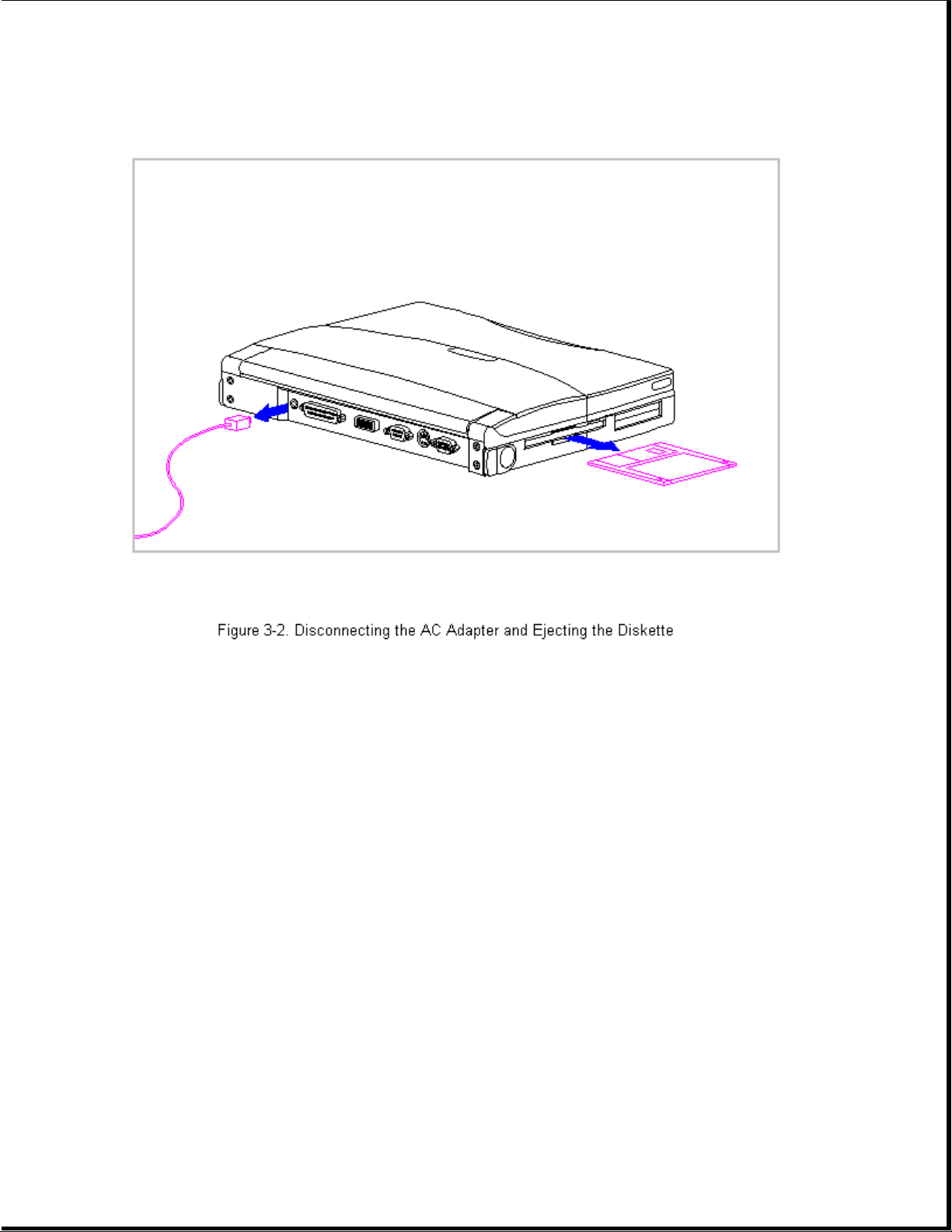
5. Disconnect the AC Adapter power cord from the computer (Figure 3-2).
6. Eject the diskette (Figure 3-2) and PC Card, if installed.
Page 51
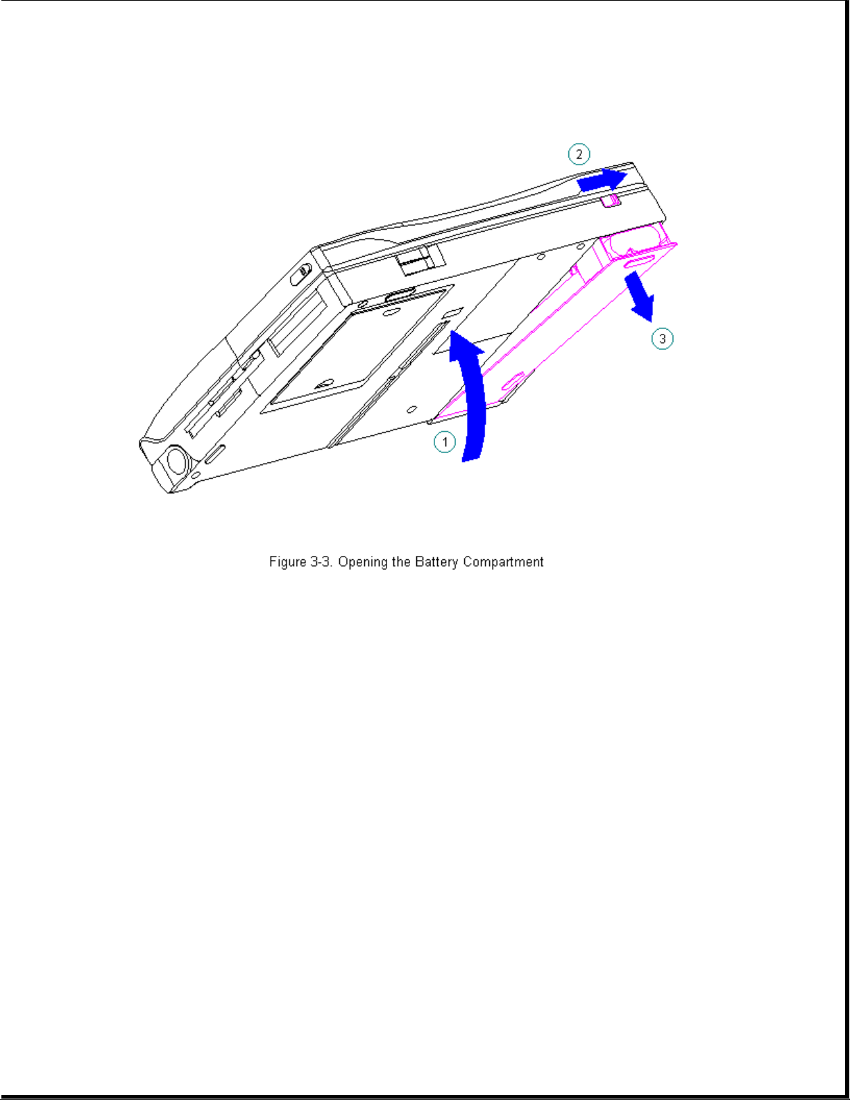
7. Open the battery compartment by lifting up the front of the computer [1]
and sliding the battery compartment release button to the right [2]. The
battery compartment opens slightly. Lower the compartment [3]
(Figure 3-3).
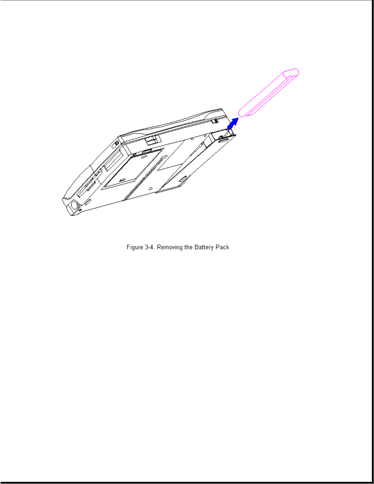
Page 52
8. Remove the battery pack (Figure 3-4).
Page 53
>>>>>>>>>>>>>>>>>>>>>>>>>>>>>>>>> CAUTION <<<<<<<<<<<<<<<<<<<<<<<<<<<<<<<<<
Metal objects can damage the battery pack and the connectors inside the
compartment. To prevent damage, do not let metal objects touch any of the
connectors. Do not place any objects other than the battery pack in the
battery compartment.
>>>>>>>>>>>>>>>>>>>>>>>>>>>>>>>>>>>>><<<<<<<<<<<<<<<<<<<<<<<<<<<<<<<<<<<<<<
9. Close the battery compartment.
Chapter 3.3 Handle Bracket
This procedure is necessary if replacing the handle bracket or if
separating the display assembly from the system unit module.
Removing the Handle Bracket
To remove the handle bracket, follow these steps:
1. Disconnect all power from the computer and remove the AC Adapter and
battery pack (Section 3.2).
Page 54
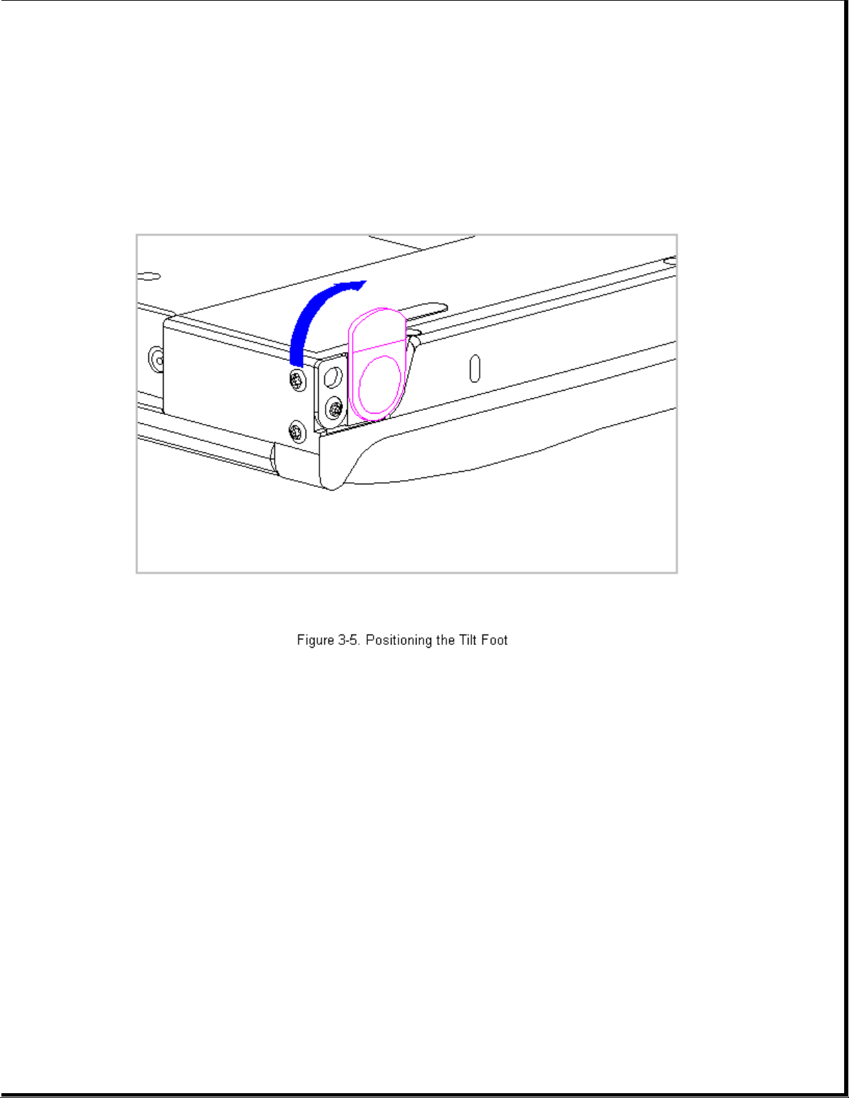
2. Close the computer and turn it top-side down.
3. Move the tilt foot toward the front of the computer, exposing the
handle bracket screw on either side of the computer (Figure 3-5).
4. Using a Torx T8 , remove the screw and washer from each handle bracket.
These screws are not reusable and must be discarded.
5. Remove the handle bracket (Figure 3-6).
Page 55

6. To install the handle bracket, reverse the previous steps. Discard the
old screws and replace with new screws.
Chapter 3.4 Tilt Feet
This procedure is necessary if replacing the tilt feet or if separating
the display assembly from the system unit module.
Removing the Tilt Feet
To remove the tilt feet, follow these steps:
1. Disconnect all power from the computer and remove the AC Adapter and
battery pack (Section 3.2).
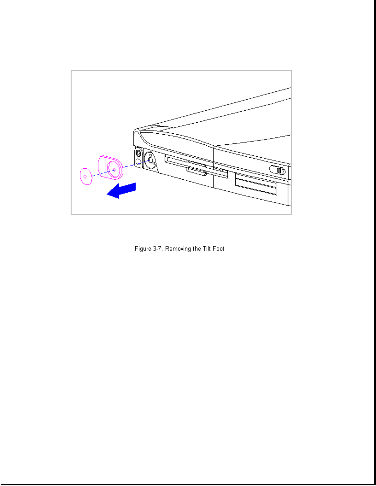
2. Using a Torx T8 , remove the tilt foot screw (Figure 3-7). Screws from
the tilt feet are not reusable and must be discarded.
3. Remove the tilt foot (Figure 3-7).
Page 56
4. To install the tilt foot, reverse the previous steps. Discard the old
screws and replace with new screws.
Chapter 3.5 Hard Drive
This section contains removal procedures for the following hard drive
components:
o Hard drive compartment cover
o Hard drive
o Hard drive bracket
Removing the Hard Drive Compartment Cover
To remove the hard drive compartment cover, follow these steps:
1. Disconnect all power from the computer and remove the battery pack,
diskette, and PC Card, if installed (Section 3.2).
Page 57
2. Close the computer and turn it top-side down.
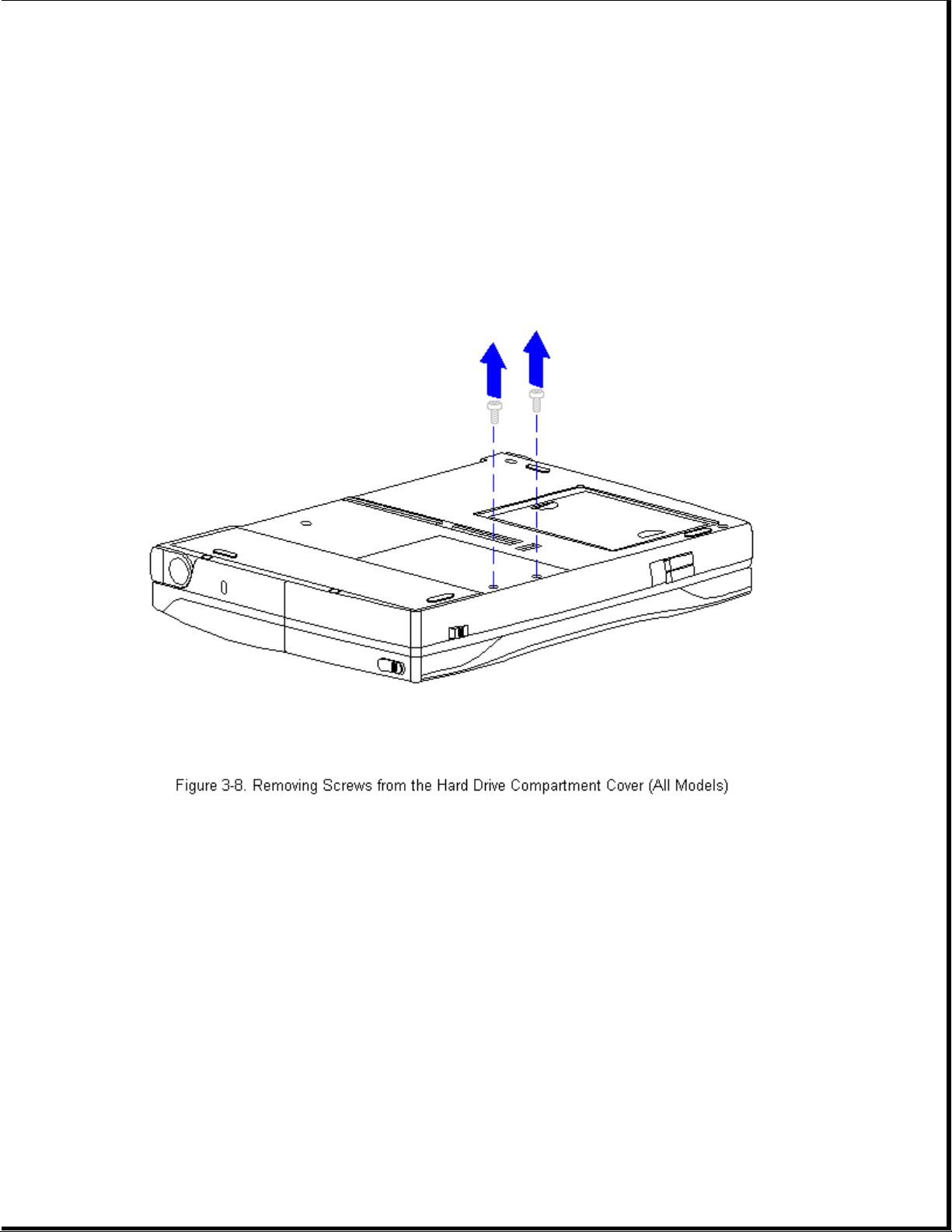
3. Using a Torx T-8 or flat-bladed screwdriver, remove the two screws from
the hard drive compartment cover (Figure 3-8).
NOTE: These two screws also secure the CPU base to the keyboard and
must be removed in order to remove the keyboard and access system
components.
4. Use a Case utility tool to remove the hard drive compartment cover
(Figure 3-9).
Page 58

5. To replace the hard drive compartment cover, reverse the previous steps
making sure to insert the bracket's tab under the plastic edge.
Removing the Hard Drive
1. Remove the hard drive compartment cover. Refer to "Removing the Hard
Drive Compartment Cover" in this section.
2. Remove the hard drive by grasping the hard drive bracket and sliding it
toward the front of the computer [1] (Figure 3-10).
3. Lift the hard drive and bracket [2] up and out of the computer
(Figure 3-10).
Page 59

4. To replace the hard drive, reverse the previous steps.
Removing the Hard Drive Bracket
1. Remove the hard drive compartment cover. Refer to "Removing the Hard
Drive Compartment Cover" in this section.
2. Remove the hard drive and bracket. Refer to "Removing the Hard Drive"
in this section.
3. Using a Torx T8 , remove the four screws from the hard drive bracket
and separate the bracket from the hard drive (Figure 3-11).
Page 60

4. To replace the hard drive bracket, reverse the previous steps.
>>>>>>>>>>>>>>>>>>>>>>>>>>>>>>>>> CAUTION <<<<<<<<<<<<<<<<<<<<<<<<<<<<<<<<<
To prevent damage to the system board connectors, ensure that the hard
drive is aligned correctly.
>>>>>>>>>>>>>>>>>>>>>>>>>>>>>>>>>>>>><<<<<<<<<<<<<<<<<<<<<<<<<<<<<<<<<<<<<<
IMPORTANT: The hard drive bracket has four screw holes, one of which is
elongated and one is small. When replacing the hard drive into
the hard drive bracket, replace the screw in the small hole
first [1], then insert the second screw into the elongated
screw hole [2] (Figure 3-12).
Page 61

Chapter 3.6 Memory Expansion Board
This section contains removal and replacement procedures for the memory
compartment cover and the memory expansion board.
The memory compartment cover and the bottom of the CPU base are embossed
with arrows and two icons that indicate whether the memory compartment
cover is unlocked [1] or locked [2].
Page 62

Removing and Replacing the Memory Compartment Cover
To remove the memory compartment cover, follow these steps:
1. Disconnect all power from the computer and remove the battery pack,
diskette, and PC Card, if installed (Section 3.2).
2. Close the computer and turn it top-side down.
3. Slide the memory compartment cover toward the rear of the computer and
lift up (Figure 3-14).
IMPORTANT: Be sure to maintain the same orientation of the cover to the
computer when removing and replacing.
Page 63

4. To replace the memory compartment cover, reverse the previous steps.
Removing the Memory Expansion Board
To remove the memory expansion board, follow these steps:
1. Remove the memory compartment cover. Refer to "Removing and Replacing
the Memory Compartment Cover" in this section.
2. Gently rock the memory expansion board back and forth, disconnecting
the board from both connectors (Figure 3-15).
Page 64

Replacing the Memory Expansion Board
To replace the memory expansion board, follow these steps:
1. Align the two connectors on the memory expansion board with the
corresponding connectors on the system board.
>>>>>>>>>>>>>>>>>>>>>>>>>>>>>>>>> CAUTION <<<<<<<<<<<<<<<<<<<<<<<<<<<<<<<<<
To prevent damage to the memory expansion board, do not apply pressure to
the middle of the board. Press only in the area directly over each
connector.
>>>>>>>>>>>>>>>>>>>>>>>>>>>>>>>>>>>>><<<<<<<<<<<<<<<<<<<<<<<<<<<<<<<<<<<<<<
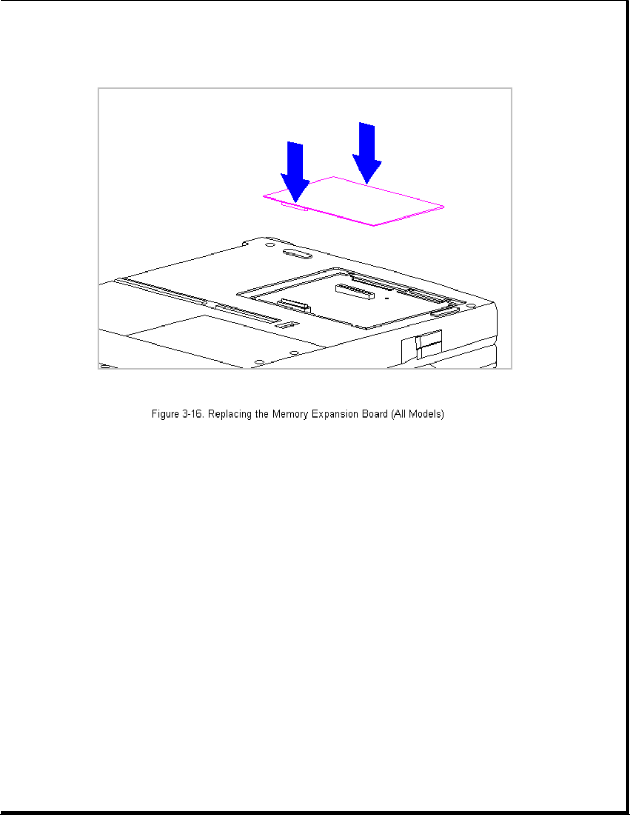
2. Insert the memory expansion board into the compartment and press the
memory expansion board down. Apply pressure directly over each
connector. Ensure that both connectors snap into place (Figure 3-16).
Page 65
3. Replace the memory compartment cover. Refer to " Removing and Replacing
the Memory Compartment Cover" in this section.
Chapter 3.7 Keyboard Assembly
This section contains removal and replacement procedures for the following
the keyboard assembly components:
o CPU cover
o Keyboard
o Top PC Card door and spring
NOTE: The bottom PC Card door and spring are part of the CPU base.
Removing the Keyboard Assembly
To remove the keyboard assembly, follow these steps:
1. Disconnect all power from the computer and remove the AC Adapter and
Page 66
battery pack (Section 3.2).
2. Close the computer and turn it top-side down.
>>>>>>>>>>>>>>>>>>>>>>>>>>>>>>>>> CAUTION <<<<<<<<<<<<<<<<<<<<<<<<<<<<<<<<<
Screws in the computer are not interchangeable. As you remove screws,
place them with the components you removed. Damage may occur if you
insert the screws in the wrong place.
>>>>>>>>>>>>>>>>>>>>>>>>>>>>>>>>>>>>><<<<<<<<<<<<<<<<<<<<<<<<<<<<<<<<<<<<<<
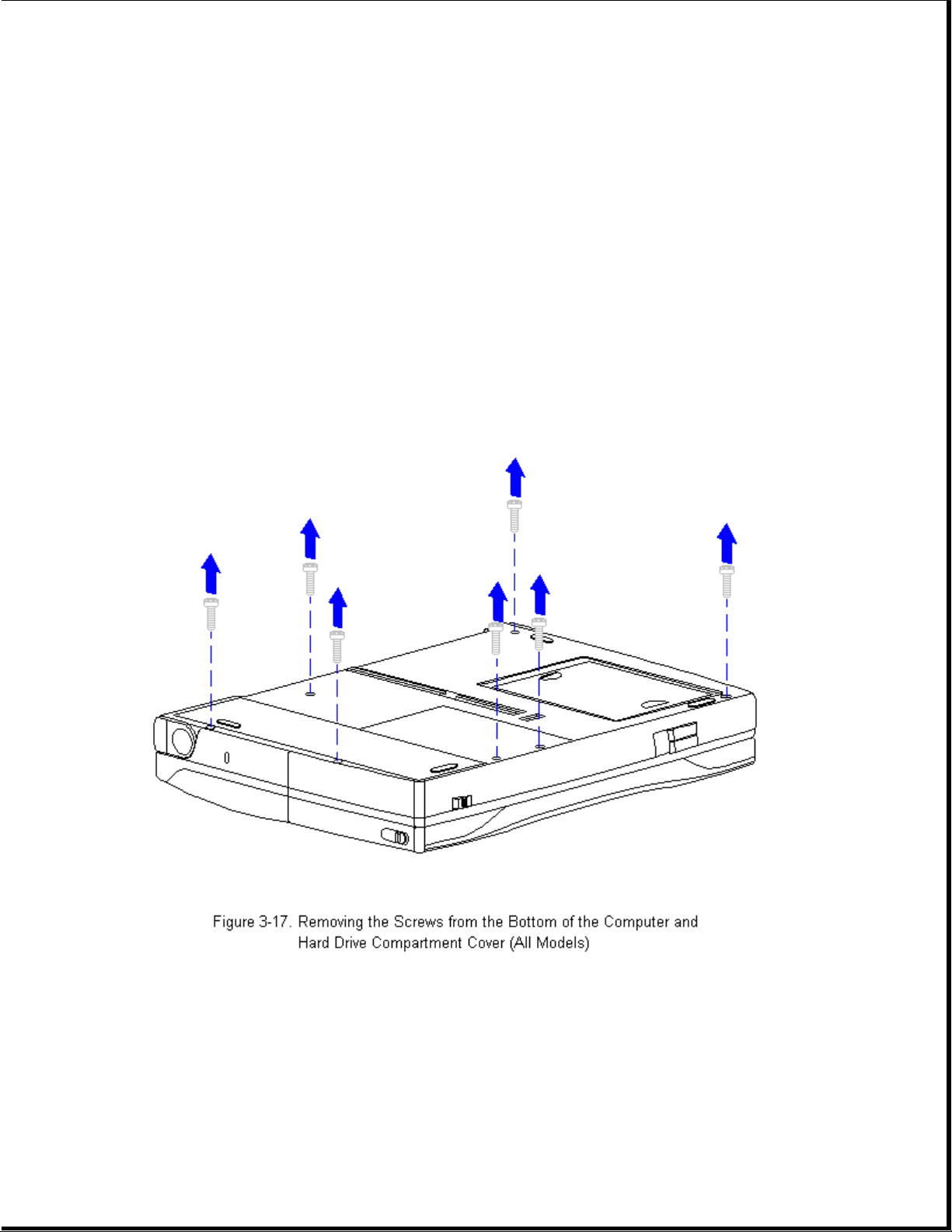
3. Using a Torx T-8 or flat-bladed screwdriver, remove the five screws
from the bottom of the computer and two screws from the hard drive
compartment cover (Figure 3-17).
Page 67

4. Use a case utility tool to remove the hard drive compartment cover
(Figure 3-18).
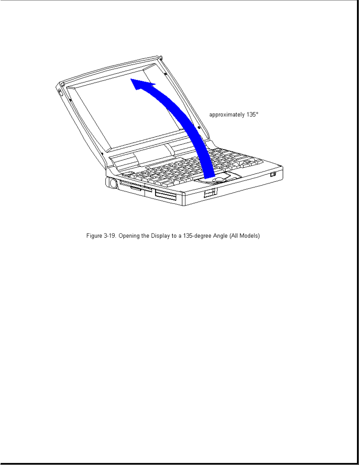
5. Carefully, turn the computer top-side up and open the display to its
fully opened position (135-degree angle) (Figure 3-19).
Page 68
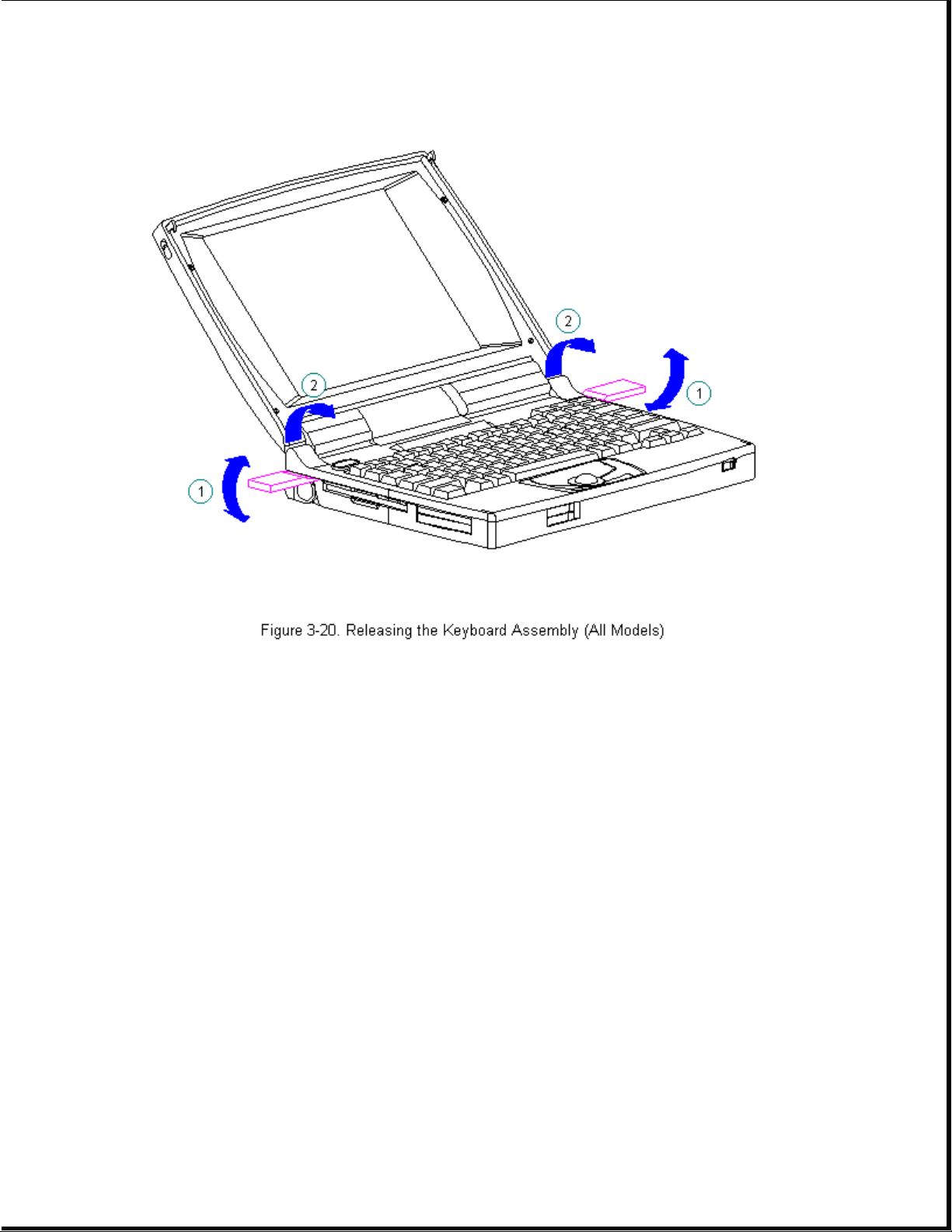
6. Using the case utility tool, lift up the outside rear corners of the
keyboard assembly to release the keyboard snaps [1], and tilt the
keyboard assembly toward you to release the keyboard connector [2]
(Figure 3-20).
IMPORTANT: When using the case utility tool, use care to keep it out of
the diskette drive area.
Page 69
>>>>>>>>>>>>>>>>>>>>>>>>>>>>>>>>> CAUTION <<<<<<<<<<<<<<<<<<<<<<<<<<<<<<<<<
The computer becomes top heavy when the keyboard assembly is removed and
the display is opened. To prevent damage to the display and the computer,
be sure to support the computer when opening the display.
>>>>>>>>>>>>>>>>>>>>>>>>>>>>>>>>>>>>><<<<<<<<<<<<<<<<<<<<<<<<<<<<<<<<<<<<<<
7. Remove the keyboard assembly by lifting it up [1] and off the front of
the computer [2] (Figure 3-21).
Page 70

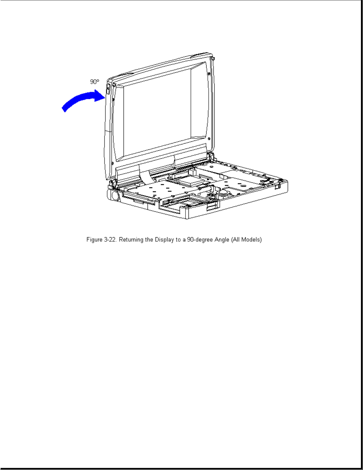
8. Position the display to a 90-degree angle (Figure 3-22).
Page 71
Removing the CPU Cover
To remove the CPU cover for replacement, follow these steps.
1. Remove the keyboard assembly from the computer. Refer to "Removing the
Keyboard Assembly" in this section.
2. Turn the keyboard assembly top-side down.
>>>>>>>>>>>>>>>>>>>>>>>>>>>>>>>>> CAUTION <<<<<<<<<<<<<<<<<<<<<<<<<<<<<<<<<
Note the position of the screws removed from the bottom of the keyboard
assembly. The remaining screws holes are for the screws that go through
the keyboard assembly to the CPU base.
>>>>>>>>>>>>>>>>>>>>>>>>>>>>>>>>>>>>><<<<<<<<<<<<<<<<<<<<<<<<<<<<<<<<<<<<<<
3. Using a Torx T-8 or flat-bladed screwdriver, remove the seven screws on
the bottom of the keyboard assembly (Figure 3-23).
IMPORTANT: Some computers will have a light director located in the status
panel. When removing the CPU cover from the keyboard, the light
director will come loose. Be sure to replace the light director
in the status panel when replacing the CPU cover to the keyboard.
Page 72
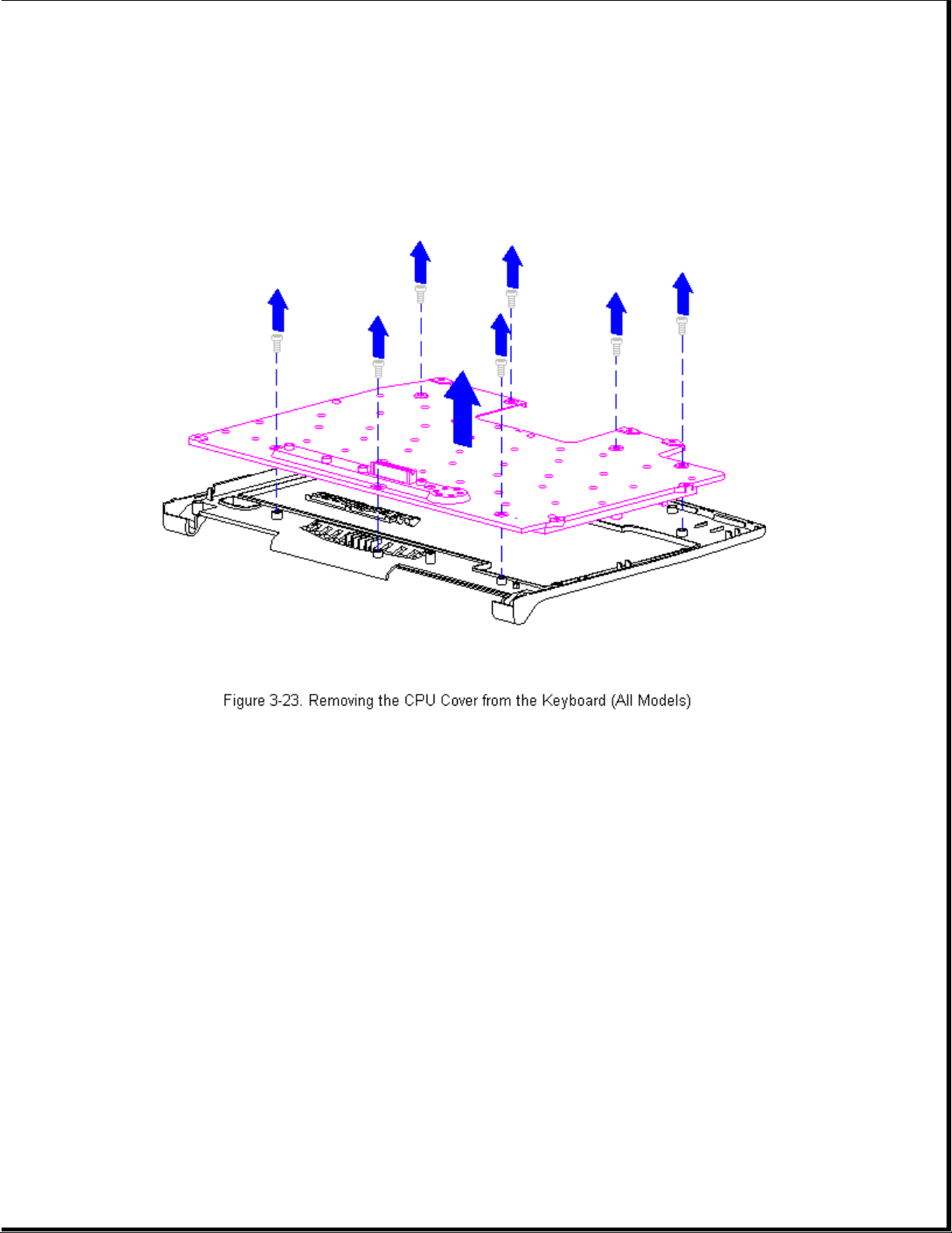
4. Separate the CPU cover from the keyboard (Figure 3-23).
5. To replace the CPU cover, reverse the previous steps.
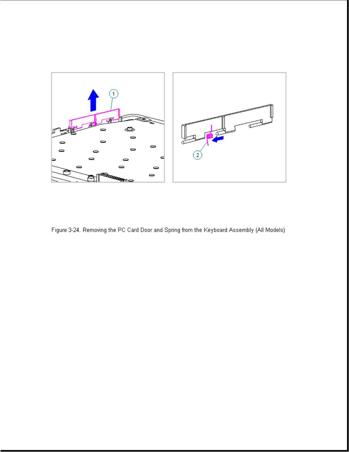
Removing the Top PC Card (PCMCIA) Door and Spring
To remove the top PC Card door and spring from the keyboard assembly,
follow these steps:
1. Remove the keyboard assembly from the computer. Refer to "Removing the
Keyboard Assembly" in this section.
2. Turn the keyboard assembly top-side down.
3. Remove the PC Card door from the keyboard assembly, unsnap the PC Card
door [1] from the posts, and remove the door (Figure 3-24).
4. Remove the spring [2] from the PC Card door (Figure 3-24).
Page 73
Replacing the Top PC Card (PCMCIA) Door and Spring
To replace the top PC Card Door and Spring to the keyboard assembly,
follow these steps:
1. Install the PC Card spring on the door post, ensuring that the bent arm
of the spring is placed against the rib on the PC Card door
(Figure 3-25).
Page 74

2. Install the PC Card (PCMCIA) door, ensuring that the spring is placed
between the post [1] and the rib [2] (Figure 3-26).
Page 75

Replacing the Keyboard Assembly
If installing a new keyboard assembly, the hook and loop fastener will
have to be attached to the diskette drive bracket:
To attach the hook and loop fastener to the diskette drive bracket, follow
these steps:
1. Separate the new hook and loop fastener.
2. Attach the opposite color of the hook and loop fastener to the existing
hook and loop fastener on the tab on the diskette drive bracket [1]
(Figure 3-27).
3. Remove the top layer from the hook and loop fastener to expose the
adhesive strip prior to replacing the keyboard assembly [2]
(Figure 3-27).
Page 76

To replace the existing keyboard assembly in the computer, follow these
steps:
1. Open the display to its fully opened position of 135-degrees
(Figure 3-28).
Page 77

2. Angle the front end of the keyboard assembly into place at the front
edge of the system unit module.
3. Ensure that the front plastic seams of the keyboard assembly and the
front of the system unit module are aligned and flush with each other.
4. Carefully lower the rear of the keyboard assembly to the system unit
module and press the outside rear corners until the keyboard assembly
snaps into place.
5. Verify the alignment of the keyboard assembly to the computer base.
Check the seams between the front and side edges of the computer base
and the keyboard assembly. If the seam is uneven, remove the keyboard
assembly and correctly align the tabs and recesses.
6. Press firmly in the center of the keyboard assembly below the status
panel [1] to connect the keyboard connector [2] to the system board [3]
(Figure 3-29).
Page 78

Chapter 3.8 Battery Compartment Components
This section contains removal procedures for the following battery
compartment components:
o Battery compartment
o Anti-skid pad
o Battery release button spring
o Battery release button
Removing the Battery Compartment
To remove the battery compartment components, follow these steps:
1. Disconnect all power from the computer and remove the AC Adapter and
battery pack (Section 3.2).
2. Turn the computer top-side down.
3. Gently squeeze in the sides of the compartment, rocking it back and
Page 79

forth, then lifting it up from the bottom of the base (Figure 3-30).
4. To replace the battery compartment, reverse the previous steps.
Attaching the Anti-Skid Pads
If installing a new battery compartment, two anti-skid pads must be
attached to the bottom of the battery compartment. To attach the anti-skid
pads, follow these steps:
1. Peel off the top layer of one of the anti-skid pads to expose the
adhesive.
2. With the adhesive-side down, place the anti-skid pad into the raised
oval outline on the battery compartment (Figure 3-31).
Page 80
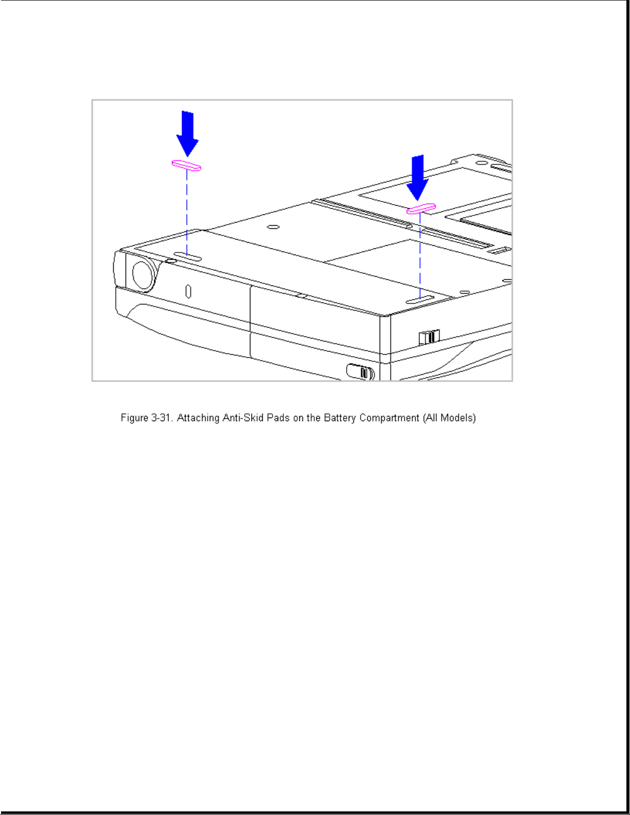
Removing the Battery Release Spring and Button
To remove the battery release spring and button, follow these steps:
1. Disconnect all power from the computer and remove the AC Adapter and
battery pack (Section 3.2).
>>>>>>>>>>>>>>>>>>>>>>>>>>>>>>>>> CAUTION <<<<<<<<<<<<<<<<<<<<<<<<<<<<<<<<<
The computer becomes top heavy when the keyboard assembly is removed and
the display is opened. To prevent damage to the display and the computer,
ensure that the display assembly is opened to a 90-degree angle.
>>>>>>>>>>>>>>>>>>>>>>>>>>>>>>>>>>>>><<<<<<<<<<<<<<<<<<<<<<<<<<<<<<<<<<<<<<
2. Remove the keyboard assembly (Section 3.7).
3. From the battery enclosure, remove the battery release button spring by
unhooking the spring from the post on the CPU base [1], then releasing
it from the hook on the battery release button [2] (Figure 3-32).
Page 81

4. Rotate the battery release button counterclockwise, until it bows
slightly, and lift it up to clear the hook on the computer base
(Figure 3-33).
Page 82
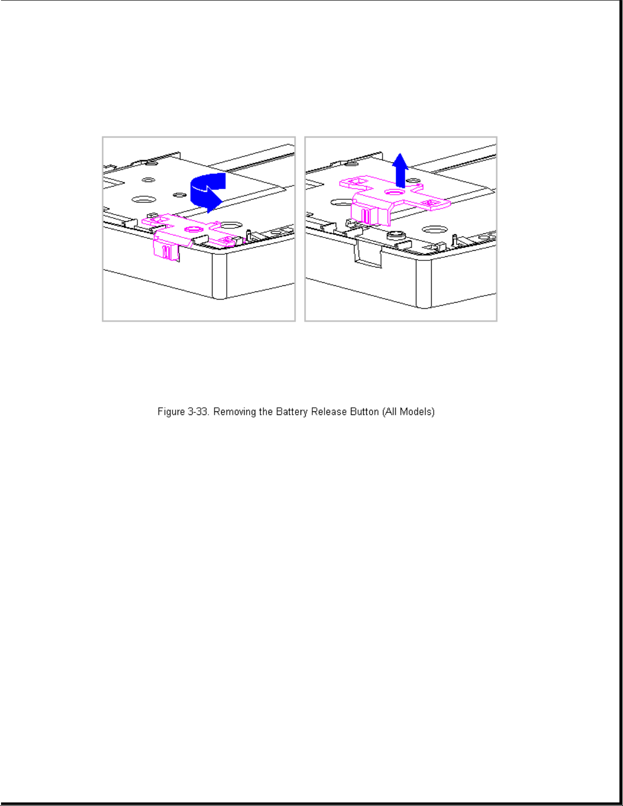
5. To replace the battery release button and spring, reverse the previous
steps.
Chapter 3.9 Real-Time Clock Battery (Models 400 and 410)
To remove the real-time clock battery, follow these steps:
1. Disconnect all power from the computer and remove the AC Adapter and
battery pack (Section 3.2).
>>>>>>>>>>>>>>>>>>>>>>>>>>>>>>>>> CAUTION <<<<<<<<<<<<<<<<<<<<<<<<<<<<<<<<<
The computer becomes top heavy when the keyboard assembly is removed and
the display is opened. To prevent damage to the display and the computer,
ensure that the display assembly is opened to a 90-degree angle.
>>>>>>>>>>>>>>>>>>>>>>>>>>>>>>>>>>>>><<<<<<<<<<<<<<<<<<<<<<<<<<<<<<<<<<<<<<
2. Remove the keyboard assembly (Section 3.7).
3. Remove the real-time clock battery from the system board by inserting a
Page 83
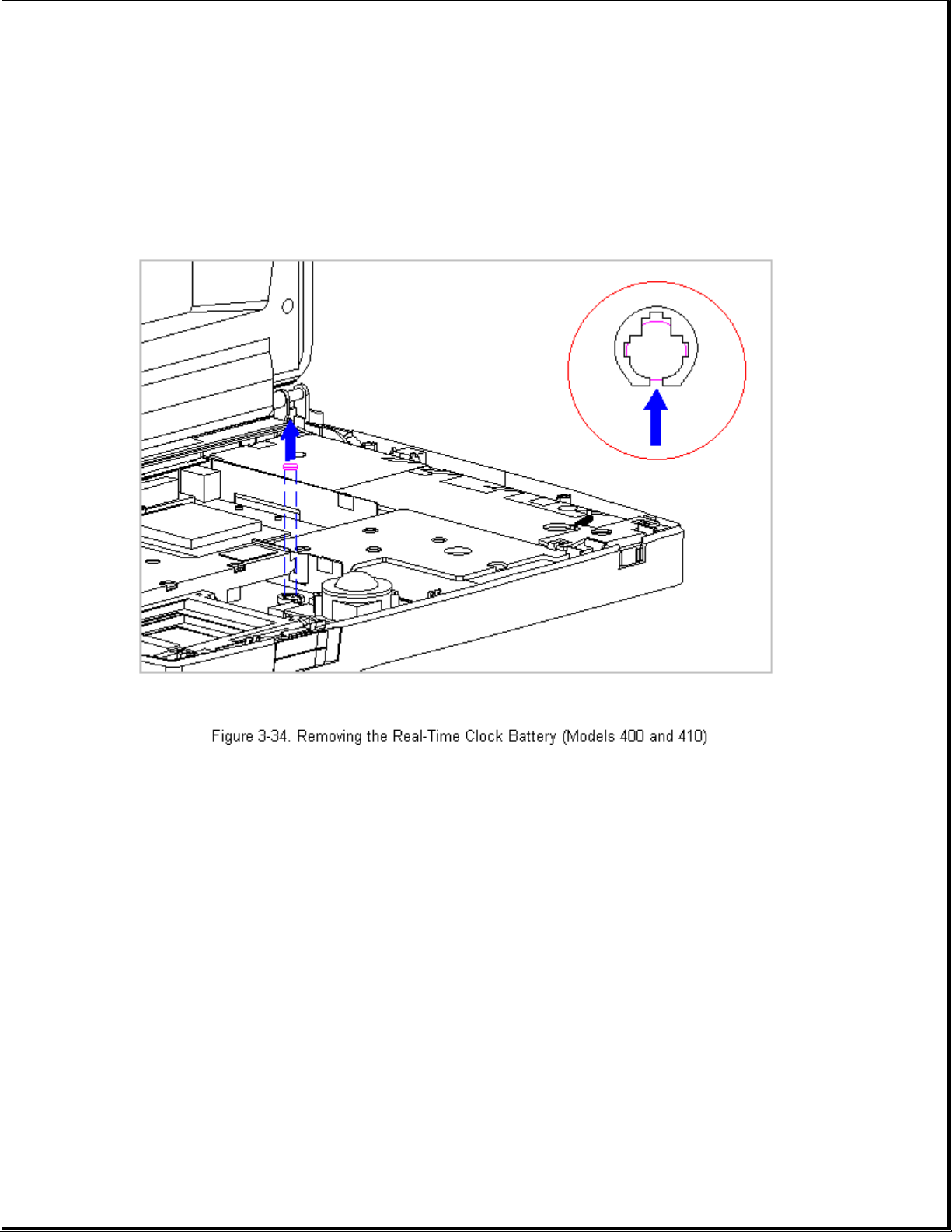
non conductive probe into the battery holder and pushing back on the
battery to release it (Figure 3-34).
NOTE: Refer to Chapter 2 "Preparing the Computer for Service" for battery
disposal procedures.
>>>>>>>>>>>>>>>>>>>>>>>>>>>>>>>>> CAUTION <<<<<<<<<<<<<<<<<<<<<<<<<<<<<<<<<
Do not touch the bottom of the battery during replacement.
>>>>>>>>>>>>>>>>>>>>>>>>>>>>>>>>>>>>><<<<<<<<<<<<<<<<<<<<<<<<<<<<<<<<<<<<<<
4. To replace the real-time clock battery, reverse the previous steps.
Chapter 3.10 Real-Time Clock Battery (Models 420 and 430)
To remove the real-time clock battery, follow these steps:
1. Disconnect all power from the computer and remove the AC Adapter and
battery pack (Section 3.2).
>>>>>>>>>>>>>>>>>>>>>>>>>>>>>>>>> CAUTION <<<<<<<<<<<<<<<<<<<<<<<<<<<<<<<<<
Page 84
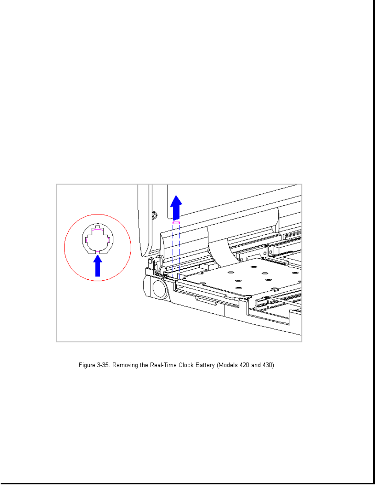
The computer becomes top heavy when the keyboard assembly is removed and
the display is opened. To prevent damage to the display and the computer,
ensure that the display assembly is opened to a 90-degree angle.
>>>>>>>>>>>>>>>>>>>>>>>>>>>>>>>>>>>>><<<<<<<<<<<<<<<<<<<<<<<<<<<<<<<<<<<<<<
2. Remove the keyboard assembly (Section 3.7).
3. Remove the real-time clock battery from the system board by inserting a
non conductive probe into the battery holder and pushing back on the
battery to release it (Figure 3-35).
NOTE: Refer to Chapter 2 "Preparing the Computer for Service" for battery
disposal procedures.
>>>>>>>>>>>>>>>>>>>>>>>>>>>>>>>>> CAUTION <<<<<<<<<<<<<<<<<<<<<<<<<<<<<<<<<
Do not touch the bottom of the battery during replacement.
>>>>>>>>>>>>>>>>>>>>>>>>>>>>>>>>>>>>><<<<<<<<<<<<<<<<<<<<<<<<<<<<<<<<<<<<<<
4. To replace the real-time clock battery, reverse the previous steps.
Page 85

Chapter 3.11 Processor Upgrade Option (Model 400 Only)
This section provides installation and replacement procedures for the
processor upgrade. The Compaq Contura 400 is the only model with the
DX2/40 MHz Processor that can be upgraded to a DX2/50 MHz processor. Once
the processor is installed, the upgraded processor overrides control of
the processor on the system board. You do not have to remove the system
board processor.
NOTE: Use only the DX2/50 MHz processor in the upgrade option slot.
To install the processor upgrade option, do the following:
1. Disconnect all power from the computer and remove the AC Adapter and
battery pack (Section 3.2).
>>>>>>>>>>>>>>>>>>>>>>>>>>>>>>>>> CAUTION <<<<<<<<<<<<<<<<<<<<<<<<<<<<<<<<<
The computer becomes top heavy when the keyboard assembly is removed and
the display is opened. To prevent damage to the display and the computer,
ensure that the display assembly is opened at a 90-degree angle.
>>>>>>>>>>>>>>>>>>>>>>>>>>>>>>>>>>>>><<<<<<<<<<<<<<<<<<<<<<<<<<<<<<<<<<<<<<
2. Remove the keyboard assembly (Section 3.7).
3. Disconnect the processor board from the two connectors on the system
board (Figure 3-36).
Page 86
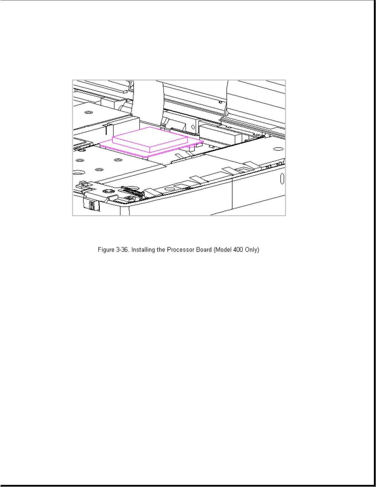
4. To remove the processor upgrade, reverse the previous steps.
Chapter 3.12 Integrated Mechanical Trackball Assembly
(Models 400 and 410)
IMPORTANT: The mechanical trackball assembly is not interchangeable with
the optical trackball assembly in Models 420 and 430.
To remove the integrated mechanical trackball assembly, follow these steps:
1. Disconnect all power from the computer and remove the AC Adapter and
battery pack (Section 3.2).
>>>>>>>>>>>>>>>>>>>>>>>>>>>>>>>>> CAUTION <<<<<<<<<<<<<<<<<<<<<<<<<<<<<<<<<
The computer becomes top heavy when the keyboard assembly is removed and
the display is opened. To prevent damage to the display and the computer,
ensure that the display assembly is opened at a 90-degree angle.
>>>>>>>>>>>>>>>>>>>>>>>>>>>>>>>>>>>>><<<<<<<<<<<<<<<<<<<<<<<<<<<<<<<<<<<<<<
Page 87
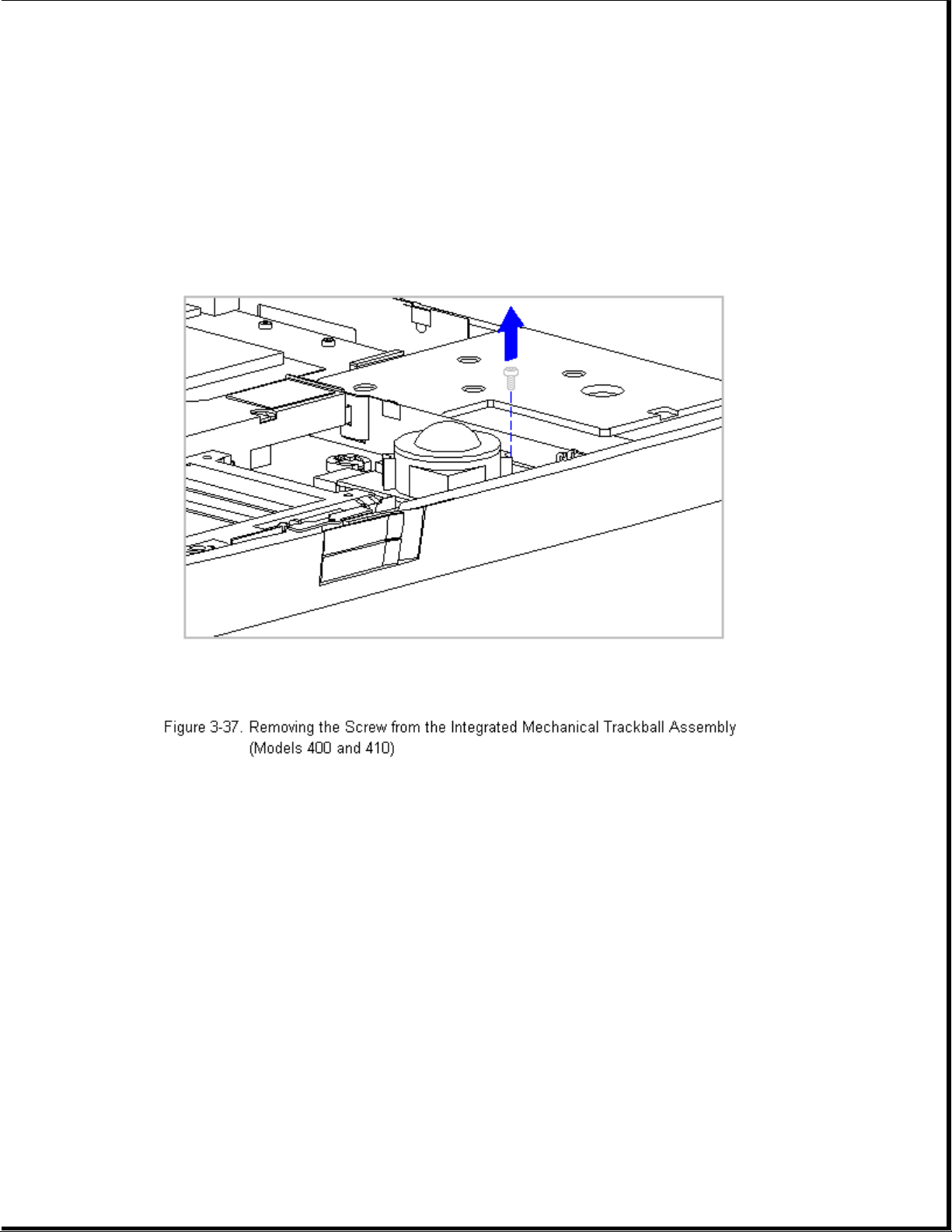
2. Remove the keyboard assembly (Section 3.7).
3. Using a Torx T-8 or flat-bladed screwdriver, remove the screw from the
front right-hand corner of the integrated mechanical trackball assembly
(Figure 3-37).
4. Disconnect the integrated mechanical trackball assembly from the system
board by pulling forward on the integrated mechanical trackball
assembly until it stops.
5. Tilt up the front of the integrated mechanical trackball assembly and
lift it up to clear the connectors and the system board (Figure 3-38).
Page 88
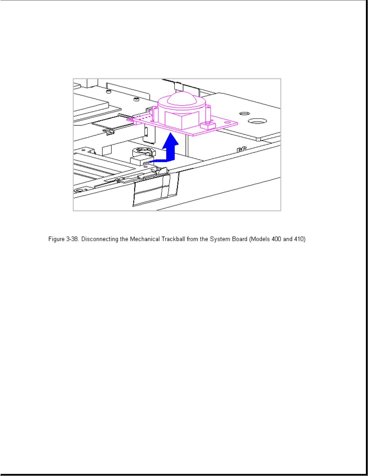
6. To replace the integrated mechanical trackball assembly, reverse the
previous steps.
Trackball Cleaning Procedures
1. Turn off the computer by pressing the left Ctrl+Alt keys and the power
button. Disconnect the AC power and remove the battery pack.
2. Loosen the trackball retaining ring by placing the trackball tool over
the retaining ring and turning the tool counterclockwise one quarter
turn.
3. Carefully remove the retaining ring. This is a delicate part and
repetitious handling of this piece may cause it to tear.
4. Remove the ball from its cage by gently lifting the computer and
turning it over so that the ball falls into your hand.
>>>>>>>>>>>>>>>>>>>>>>>>>>>>>>>>> CAUTION <<<<<<<<<<<<<<<<<<<<<<<<<<<<<<<<<
Do not soak components, and do not use any solvents other than isopropyl
(rubbing) alcohol!
Page 89

>>>>>>>>>>>>>>>>>>>>>>>>>>>>>>>>>>>>><<<<<<<<<<<<<<<<<<<<<<<<<<<<<<<<<<<<<<
5. Clean the trackball with isopropyl (rubbing) alcohol only. Dry it with
a clean, lint-free cloth. DO NOT USE AN ABRASIVE CLEANER.
>>>>>>>>>>>>>>>>>>>>>>>>>>>>>>>>> CAUTION <<<<<<<<<<<<<<<<<<<<<<<<<<<<<<<<<
If a foam-tipped swap is not available, you can use a cotton swab. But use
a cotton swap only once and then discard it as it may scratch the
trackball.
>>>>>>>>>>>>>>>>>>>>>>>>>>>>>>>>>>>>><<<<<<<<<<<<<<<<<<<<<<<<<<<<<<<<<<<<<<
6. Gently wipe the cage to remove residue from the surface. Clean the ball
bearings by rubbing with the swab. Do not attempt to remove the
bearings. Next, gently swab the rollers from side to side until all
buildup is removed. Rotate rollers to ensure that all surfaces are
cleaned.
7. Be sure not to leave any cotton fibers on any part of the trackball
components. Use tweezers to remove any fibers that may have accumulated
on or around the cage, rollers, or support post.
8. Let the unit air dry before reassembling it.
9. To reassemble, place the computer right side up and place the cleaned
ball into its cage.
10. Gently replace the retaining ring by aligning the notches; then use
the trackball tool to turn it clockwise one quarter turn until it
locks into place.
11. Use the trackball to verify that it works properly without skipping or
sticking.
Chapter 3.13 Integrated Optical Trackball Assembly (Models 420 and 430)
IMPORTANT: The optical trackball assembly is not interchangeable with the
mechanical trackball assembly in Models 400 and 410.
To remove the integrated optical trackball assembly, follow these steps:
1. Disconnect all power from the computer and remove the AC Adapter and
battery pack (Section 3.2).
>>>>>>>>>>>>>>>>>>>>>>>>>>>>>>>>> CAUTION <<<<<<<<<<<<<<<<<<<<<<<<<<<<<<<<<
The computer becomes top heavy when the keyboard assembly is removed and
the display is opened. To prevent damage to the display and the computer,
ensure that the display assembly is opened at a 90-degree angle.
Page 90

>>>>>>>>>>>>>>>>>>>>>>>>>>>>>>>>>>>>><<<<<<<<<<<<<<<<<<<<<<<<<<<<<<<<<<<<<<
2. Remove the keyboard assembly (Section 3.7).
3. Using a Torx T-8 or flat-bladed screwdriver, remove the screw from the
front right-hand corner and the left rear corner of the trackball
assembly (Figure 3-39).
4. Disconnect the integrated optical trackball assembly from the system
board by pulling upward on the trackball assembly.
Page 91

5. To replace the integrated mechanical trackball assembly, reverse the
previous steps.
Trackball Cleaning Procedures
1. Turn off the computer, disconnect AC power, and remove the battery pack.
2. Remove the Integrated trackball.
3. Remove any large particles of debris that have fallen into the
trackball housing.
4. Dip a cotton swab in isopropyl alcohol and squeeze off excess liquid.
5. Carefully wipe inside the cage to remove residue from surfaces. Clean
the ball bearings by rubbing with the swab. Do not attempt to remove
the bearings. Do not use alcohol on the sensor window. Instead, gently
wipe the sensor window with a soft, dry, lint-free cloth until all
debris is removed. Allow enough time for the parts to air dry before
reassembling.
6. Replace the ball and gently secure the retaining ring by rotating it
clockwise.
Page 92

7. Replace the battery pack and reconnect the AC power.
Chapter 3.14 Diskette Drive (All Models)
This section contains removal and replacement procedures for the following
diskette drive components:
o Diskette Drive
o Diskette Drive Bracket
o Diskette Drive Insulator Strip
Removing the Diskette Drive
To remove the diskette drive, follow these steps:
1. Disconnect all power from the computer and remove the AC Adapter and
battery pack (Section 3.2).
>>>>>>>>>>>>>>>>>>>>>>>>>>>>>>>>> CAUTION <<<<<<<<<<<<<<<<<<<<<<<<<<<<<<<<<
The computer becomes top heavy when the keyboard assembly is removed and
the display is opened. To prevent damage to the display and the computer,
ensure that the display assembly is opened to a 90-degree angle.
>>>>>>>>>>>>>>>>>>>>>>>>>>>>>>>>>>>>><<<<<<<<<<<<<<<<<<<<<<<<<<<<<<<<<<<<<<
2. Remove the keyboard assembly (Section 3.7).
3. Disconnect the diskette drive cable from the LIF connectors on the
diskette drive and the system board (Figure 3-41).
Page 93

>>>>>>>>>>>>>>>>>>>>>>>>>>>>>>>>> CAUTION <<<<<<<<<<<<<<<<<<<<<<<<<<<<<<<<<
Screws in the computer are not interchangeable. As you remove screws,
place them with the components you removed. Damage may occur if you
insert the screws in the wrong place.
>>>>>>>>>>>>>>>>>>>>>>>>>>>>>>>>>>>>><<<<<<<<<<<<<<<<<<<<<<<<<<<<<<<<<<<<<<
4. Using a Torx T-8 or flat-bladed screwdriver, remove the three diskette
drive bracket screws that screw into the system board (Figure 3-42).
Page 94

>>>>>>>>>>>>>>>>>>>>>>>>>>>>>>>>> CAUTION <<<<<<<<<<<<<<<<<<<<<<<<<<<<<<<<<
When removing or replacing the diskette drive, hold it by grasping the
vertical sides. Pressure to the front drive door area of the diskette
drive will cause the drive door to pop out from the mounting.
>>>>>>>>>>>>>>>>>>>>>>>>>>>>>>>>>>>>><<<<<<<<<<<<<<<<<<<<<<<<<<<<<<<<<<<<<<
5. Tilt up the diskette drive bracket, then lift it up and out of the
system chassis (Figure 3-43).
Page 95

Removing the Diskette Drive from the Diskette Drive Bracket
1. Remove the diskette drive from the system chassis. Refer to "Removing
the Diskette Drive" in this section.
2. Remove the diskette drive from the bracket by removing the four screws
from both sides of the bracket (Figure 3-44).
Page 96
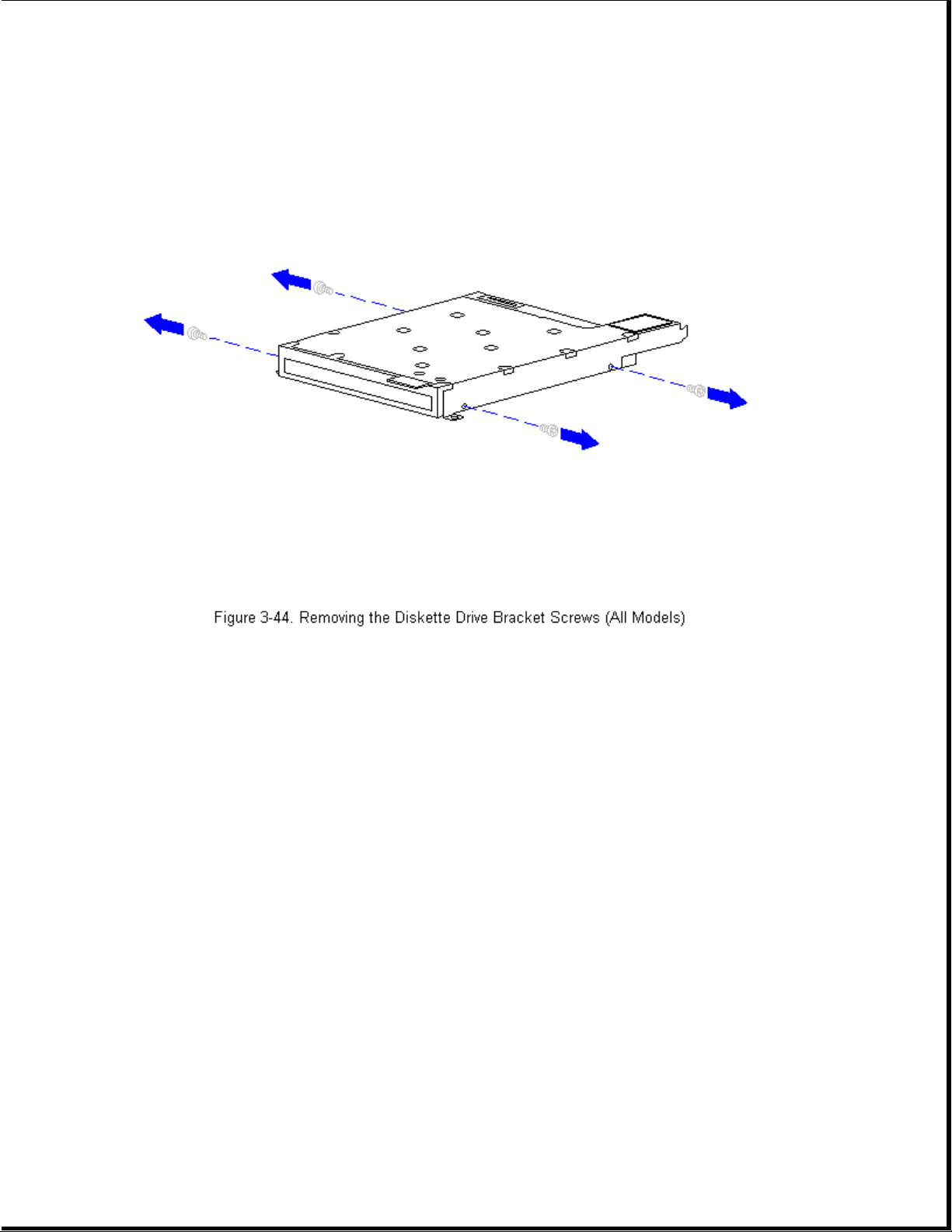
3. Separate the diskette drive from the bracket (Figure 3-45).
Page 97
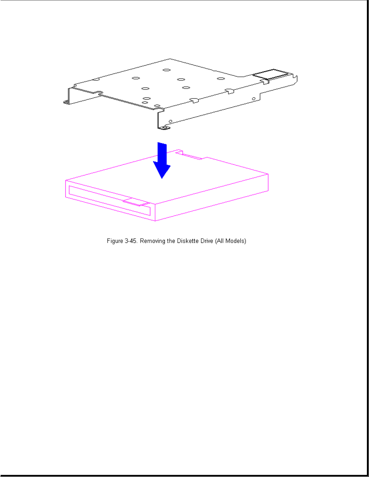
4. To replace the diskette drive into the bracket, reverse the previous
steps.
Applying the Diskette Drive Hook and Loop Fastener
If installing a new diskette drive bracket, the hook and loop fastener
must be attached to the bracket.
To attach the hook and loop fastener, follow these steps:
1. Separate the new hook and loop fastener.
2. Remove the backing from the adhesive on the hook and loop fastener that
is the opposite color of the hook and loop fastener attached to the
keyboard assembly (for example, white to black or black to white).
3. Attach the new hook and loop fastener of the opposite color of the hook
and loop fastener on the keyboard assembly to the tab on the diskette
drive bracket (Figure 3-46).
Page 98
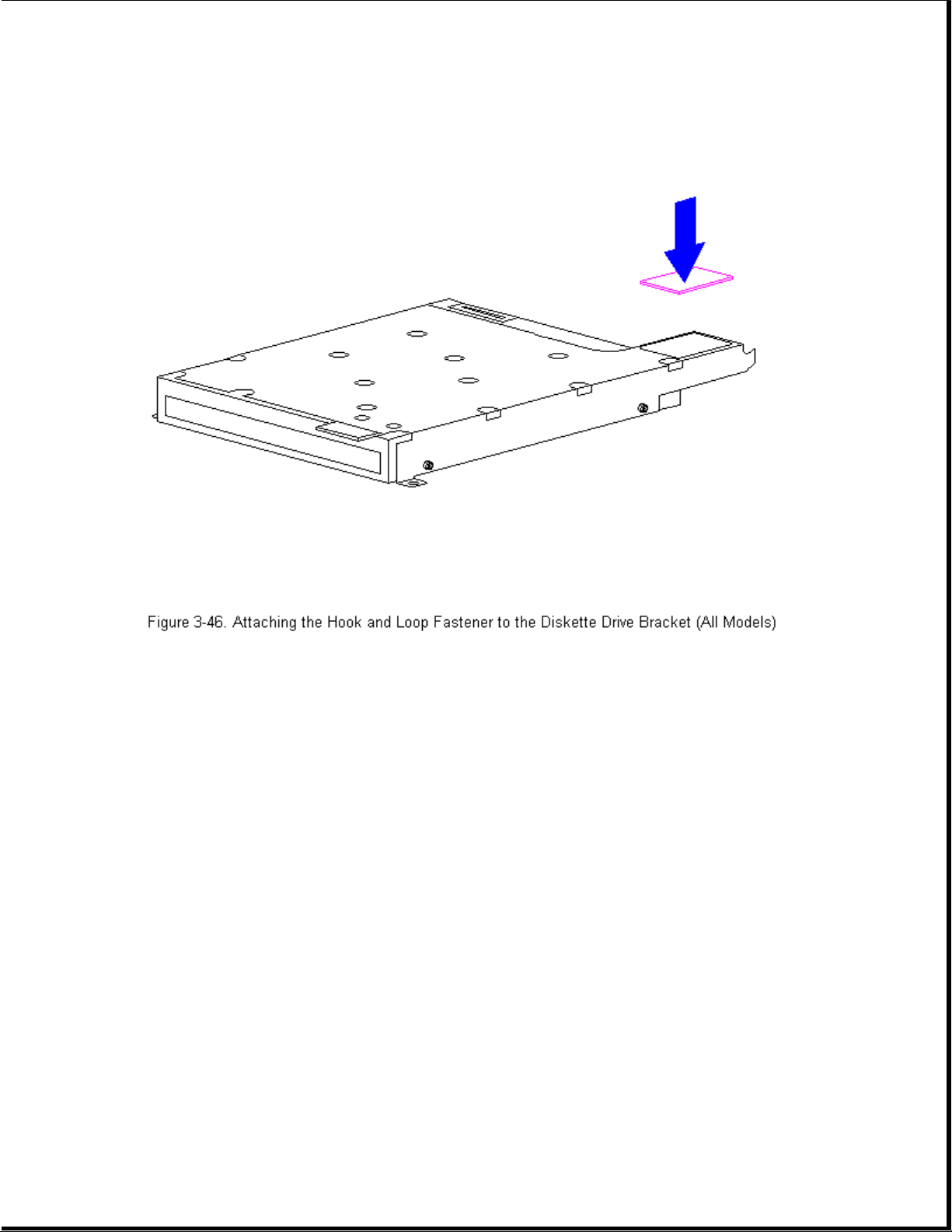
Replacing the Diskette Drive
To replace the diskette drive into the system chassis, follow these steps:
>>>>>>>>>>>>>>>>>>>>>>>>>>>>>>>>> CAUTION <<<<<<<<<<<<<<<<<<<<<<<<<<<<<<<<<
When removing or replacing the diskette drive, hold it by grasping the
vertical sides. Pressure to the front drive door area of the diskette
drive will cause the drive door to pop out from the mounting.
>>>>>>>>>>>>>>>>>>>>>>>>>>>>>>>>>>>>><<<<<<<<<<<<<<<<<<<<<<<<<<<<<<<<<<<<<<
1. Replace the diskette drive into the diskette drive bracket. Use the
four screws to secure the diskette drive to the bracket.
2. Tow in the back end of the diskette drive into the system chassis.
IMPORTANT: Ensure that the diskette drive door does not catch on the
outside edge of the system unit module.
3. Close the diskette drive door slightly while lowering the front of the
diskette drive into the system chassis (Figure 3-47).
Page 99
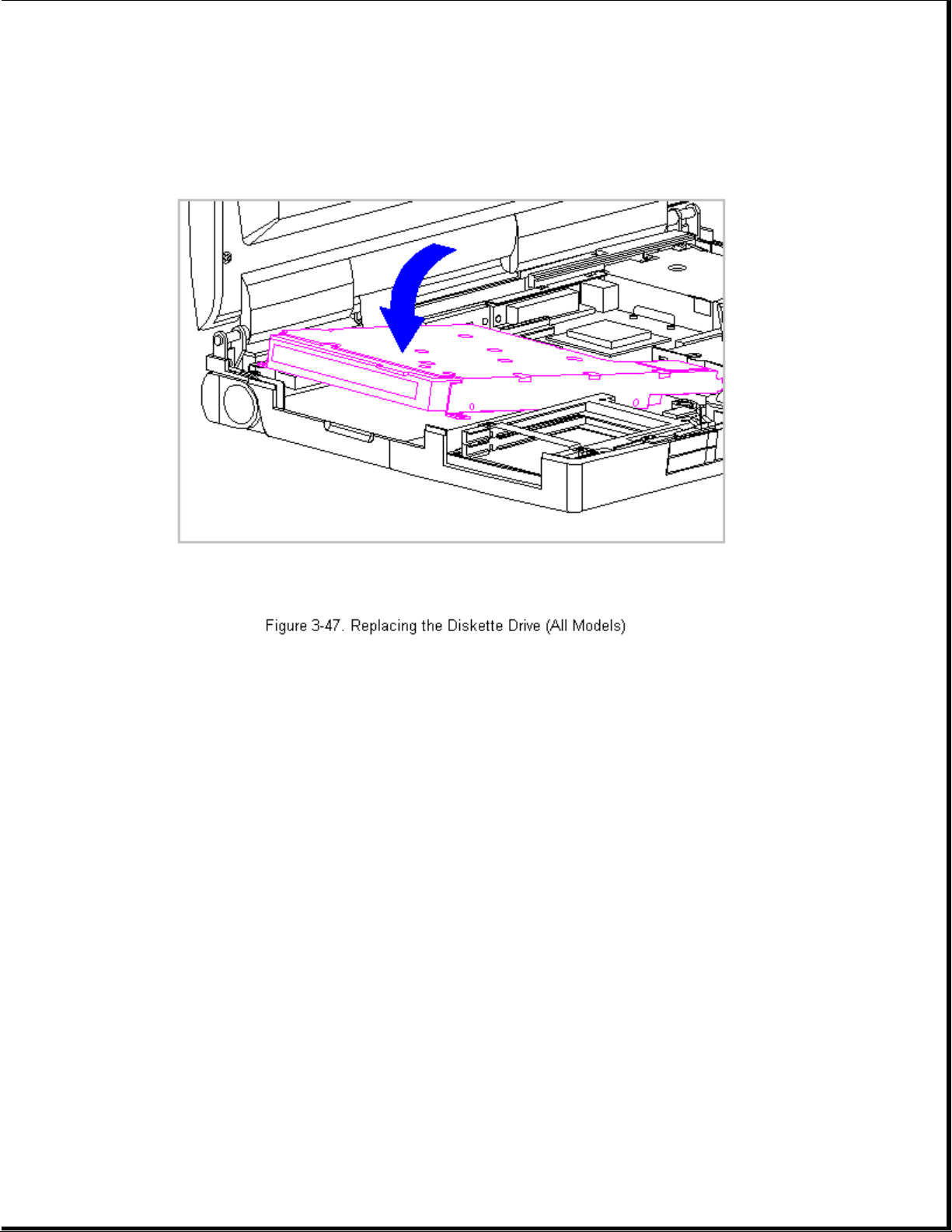
4. Reconnect the Diskette Drive Cable and reinstall the three screws.
Chapter 3.15 The System Board (All Models)
To remove the system board, follow these steps:
1. Disconnect all power from the computer and remove the AC Adapter and
battery pack (Section 3.2).
2. Remove the hard drive (Section 3.5).
3. Remove the memory expansion board, if installed (Section 3.6).
4. On the rear of the computer, use a hex socket driver to remove the six
screw locks (Figure 3-48).
5. Using a Torx-T8 driver, remove the two alignment screws from the
docking base connector (Figure 3-48).
Page 100

>>>>>>>>>>>>>>>>>>>>>>>>>>>>>>>>> CAUTION <<<<<<<<<<<<<<<<<<<<<<<<<<<<<<<<<
The computer becomes top heavy when the keyboard assembly is removed and
the display is opened. To prevent damage to the display and the computer,
ensure that the display assembly is opened at a 90-degree angle.
>>>>>>>>>>>>>>>>>>>>>>>>>>>>>>>>>>>>><<<<<<<<<<<<<<<<<<<<<<<<<<<<<<<<<<<<<<
6. Remove the keyboard assembly (Section 3.7).
7. Remove the processor upgrade, if installed (Section 3.11).
8. Remove the integrated trackball assembly (Section 3.12 for Models 400
and 410 and Section 3.13 for Models 420 and 430).
9. Remove the diskette drive (Section 3.14).
>>>>>>>>>>>>>>>>>>>>>>>>>>>>>>>>> CAUTION <<<<<<<<<<<<<<<<<<<<<<<<<<<<<<<<<
The ZIF connector and its attached cable can be damaged easily. Handle
only the connector slide when disconnecting the ZIF connector. Never pull
or twist the cable itself while it is seated in the ZIF connector.
>>>>>>>>>>>>>>>>>>>>>>>>>>>>>>>>>>>>><<<<<<<<<<<<<<<<<<<<<<<<<<<<<<<<<<<<<<
 Loading...