

Page 1
8-Channel Contact Closure Transmitter and Receiver
FDC8 SERIES
HARDENEDINCLUDED
The ComNet™ FDC8 Series contact closure transmitter and receiver provides
transmission of up to eight independent contact closures over one RS232 link or
optical fiber. Microprocessor-based logic sends the contact information in packets that
are ordered and encoded, ensuring extremely robust transmission. Packets that are
garbled, packets out of sequence, and transmission bit errors will not cause random
changes of state on the contact relays. Also, the mechanical latching relays maintain
their state even when the unit loses power. Each module incorporates power and
individual status indicating LEDs for monitoring confirmation of contact closure of each
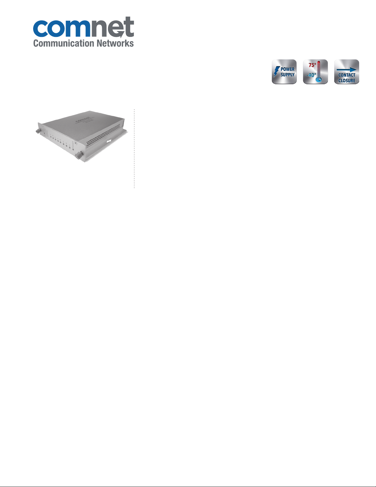
of the eight channels. Packaged in the exclusive ComNet ComFit housing, these units
may be either wall or rack-mounted, or may be DIN-rail mounted by the addition of
ComNet model DINBKT1 or DINBKT4 adaptor plate.
8
FEATURES
› Transmits up to eight contact closures over one RS232 link, or
one optical fiber
› Eight channel Point-to-Point transmission architecture
› Indicating LEDs for monitoring power and contact channels
› Eight SPST latching relays (with individual indicators)
› Tested and certified by an independent laboratory for full
compliance with the environmental requirements (ambient
operating temperature, mechanical shock, vibration, humidity
with condensation, high-line/low-line voltage conditions and
transient voltage protection) of NEMA TS -1/TS -2 and the
Caltrans Specification for Traffic Signal Control Equipment
› Microprocessor-based logic and latching relays in receiver
unit eliminate random contact closure status in the event of
loss of link or loss of prime operating power.
› Relay contact rating: 30 VDC, 1 Amp, normally open
› Automatic resettable solid-state current limiters
› Hot-swappable rack modules
› Interchangeable between stand-alone or rack mount use –
ComFit
› Lifetime Warranty
APPLICATIONS
› Alarm Event Triggering
› Building Automation and Environmental
Control Systems
› Fire and Alarm Systems
› Lane/Gate Control
› PIR Signal Transmission
LIFETIME WARRANTY WWW.COMNET.NET TECH SUPPORT: 1.888.678.9427
Page 2
FDC8 SERIES
SPECIFICATIONS
8-Channel Contact Closure Transmitter and Receiver
Contacts
Input/Output Channels 8
Input Contacts 5 VDC, 0.5 mA, normally open
Output Contacts 30 VDC, 1 Amp, normally open
Response Time 25 msec maximum
Connectors
FDC8T/R232, Contacts Terminal Block
FDC8T/R(M)(S)1 ST Optical Connectors
LED Indicators › Power
› Channel Status
› Link (receiver only)
Power
Operating Voltage Range 8 to 15 VDC (or from C1 Rack, sold separately)
Power Consumption 3 W Max
Rack From Rack
Electrical & Mechanical
Number of Rack Slots 1
Current Protection Automatic Resettable Solid-State Current Limiters
Circuit Board Meets IPC Standard
Size 6.1 × 5.3 × 1.1 in (15.5 × 13.5 × 2.8 cm)
Shipping Weight <2 lb./0.9 kg
Environmental
MTBF >100,000 hours
Operating Temp -40˚ C to +75˚ C
Storage Temp -40˚ C to +85˚ C
Relative Humidity 0% to 95% (non-condensing)¹
ORDERING INFORMATION
Fibers
Part Number Description
FDC8TM1 8-Channel Contact Closure Transmitter
FDC8RM1 8-Channel Contact Closure Receiver
FDC8TS1 8-Channel Contact Closure Transmitter
FDC8RS1 8-Channel Contact Closure Receiver
Accessories DC Plug-in Power Supply, 90-264 VAC, 50/60 Hz (Included)
Options
† Optical transmission distance is limited to optical loss of the fiber and any additional loss introduced by connectors, splices and patch
panels. Distance can also be limited by fiber bandwidth. ‡ For 50/125µm fiber, subtract 4 dB from the optical power budget.
Complies with FDA Performance Standard for Laser Products, Title 21, Code of Federal Regulations, Subchapter J
In a continuing effort to improve and advance technology, product specifications are subject to change without notice.
[1] Add ‘/C’ for Conformally Coated Circuit Boards to extend to condensation conditions (Extra charge, consult factory)
DIN-Rail Mounting Adaptor Plate Kit – With mounting hardware (Optional, order model DINBKT1 or DINBK T4)
Required Fiber
1
1 Single Mode 9/125µm 23 dB 69 km (43 miles) 1
Multimode‡
62.5/125µm or 50/125µm
Optical PWR
Budget
16 dB 16 km (10 miles) 1
Max.
Distance †
# Rack
Slots
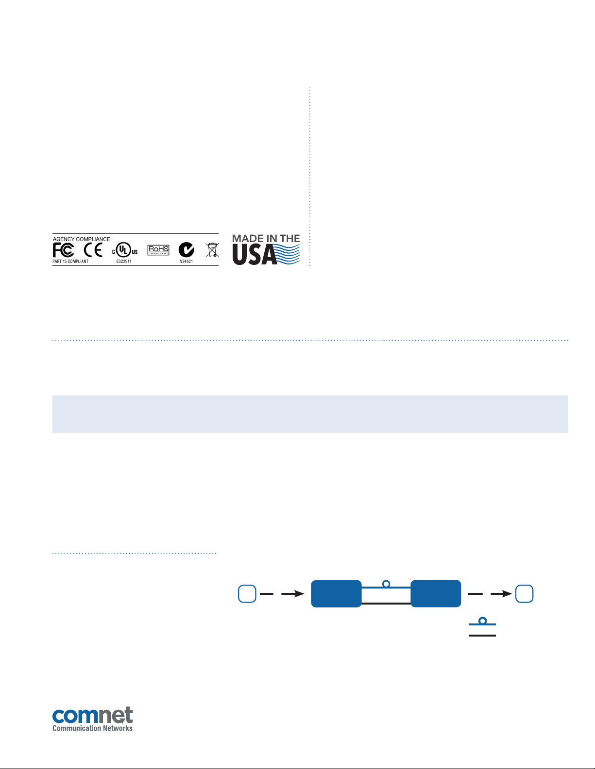
TYPICAL APPLICATION
Part Number Media Required
FDC8T232 RS232 LINK
FDC8R232 RS232 LINK
3 CORPORATE DRIVE
8 TURNBERRY PARK ROAD
C C
|
DANBURY, CONNECTICUT 06810
|
GILDERSOME
8 8
|
MORLEY
FDC8T232
|
|
USA
T: 203.796.5300
|
LEEDS, UK LS27 7LE
1 Fiber
9/125µm SM
Up to 54 km
(35 miles)
OR
1 RS232 Link
|
F: 203.796.5303
|
T: +44 (0)113 307 6400
FDC8R232
|
TECH SUPPORT: 1.888.678.9427
|
F: +44 (0)113 253 7462
|
INFO-EUROPE@COMNET.NET
OPTICAL FIBER
RS232 LINK
|
INFO@COMNET.NET
20 Nov 2014© 2014 Communic ation Netwo rks. All Righ ts Reserv ed. “ComNet ” and the “ComNe t Logo” are regi stered tra demarks of Com munication Ne tworks.
 Loading...