

Page 1
INSTALLATION AND OPERATION MANUAL
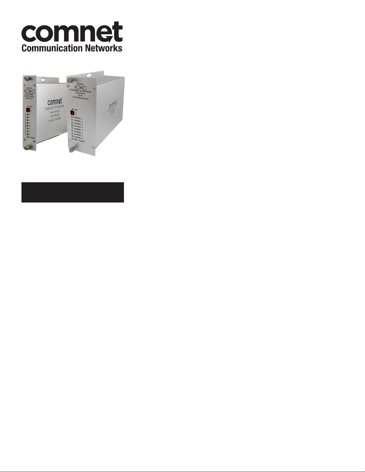
FDC80 Series
8-CHANNEL SUPERVISED CONTACT CLOSURE
This manual serves the following
ComNet Model Numbers:
FDC80TM1
FDC80RM1
FDC80NLRM1
FDC80TS1
FDC80RS1
FDC80NLRS1
FDC80T48 5
FDC80R485
FDC80NLR485
The FDC80 contact closure transmitter and receiver provide transmission of up
to eight independent supervised contact closures over either one optical fiber or
two wire RS-485 link. Microprocessor-based logic sends the contact information
in packets that are ordered and encoded, ensuring extremely robust transmission.
Packets that are garbled, packets out of sequence, and transmission bit errors will not
cause random changes of state on the contact relays. The receiver unit is offered in
both latching and non-latching relay configurations.
Multiple levels of supervision and receiver alarm control can be selected. See Figure
7 on Page 4 for switch settings.
Each module incorporates power and individual status indicating LED’s for monitoring
confirmation of contact closure of each of the eight channels. See Figure 8 on Page 4
for an explanation of the LED indicators.
These units are interchangeable between stand-alone or card mount configurations.
See Figure A on Page 7 for mounting instructions.
See Figures 1 – 11 for complete installation information, following the Application
Note on Page 6.
INS_FDC80_REV–
12/29/11
PAGE 1
Page 2
INSTALLATION AND OPERATION MANUAL FDC80
FIGURE 1 – FDC80 OPTICAL
MULTIMODE OR SINGLE MODE
OPTICAL FIBER (Depending on Model)
BLACK
BLACK WITH WHITE STRIPE
Power Supply:
Surface Mount: 8–15 VDC @ 150mA
Rack Mount: From Rack
NOTE: Remove Electrical Connector
for Rack Mount Units
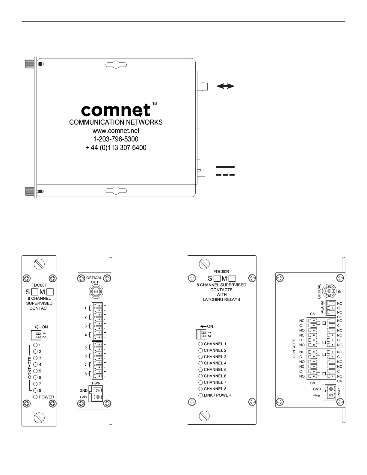
FIGURE 2 – FDC80 TRANSMITTER FIGURE 3 – FDC80 RECEIVER
REAR PANEL REAR PANELFRONT PANEL FRONT PANEL
TECH SUPPORT: 1.888.678.9427
INS_FDC80_REV–
12/29/11
PAGE 2
Page 3

INSTALLATION AND OPERATION MANUAL FDC80
FIGURE 4 – FDC80 RS-485
RS485 2 Wire
BLACK
BLACK WITH WHITE STRIPE
Power Supply:
Surface Mount: 8–15 VDC @ 150mA
Rack Mount: From Rack
NOTE: Remove Electrical Connector
for Rack Mount Units
FIGURE 5 – FDC80 RS-485 TRANSMITTER FIGURE 6 – FDC80 RS-485 RECEIVER
REAR PANEL REAR PANELFRONT PANEL FRONT PANEL
TECH SUPPORT: 1.888.678.9427
INS_FDC80_REV–
12/29/11
PAGE 3
Page 4

INSTALLATION AND OPERATION MANUAL FDC80
FIGURE 7 – SWITCH SETTINGS
The switch is located on the front panel of each unit.
Transmitter
1 - Series Supervision
2 - Parallel Supervision
Receiver
1 - Fiber Alarm
2 - Contact Fault Alarm
TX: The transmitter switch selects the supervision method, and this information is automatically transmitted to the receiver module.
There are four levels of supervision.
NONE: S1-OFF, S2-OFF. No supervision is active. The contact will show as closed when the inputs are shorted, and open when the
input are open. The associated LED will be either GREEN (closed) or OFF (open).
Series: S1-ON, S2-OFF. Series termination is when a 1K resistor is connected in series with the relay input. In this mode, shorts
across the contact inputs can be detected. When the relay is closed normally, the LED indicator will be GREEN, when open it will be
OFF, when shorted, the LED will flash RED slow.
Parallel: S1-OFF, S2-ON. Parallel termination is when a 1K resistor is connected in parallel, across the contact input. In this mode,
cut wires can be detected. When the relay is closed normally, the LED indicator will be GREEN, when open it will be OFF, and when
cut, it will flash RED fast.
Full Supervision: S1-ON, S2-ON. Full Supervision is when a 1K resistor is connected in series with the contact input, and a 1K
resistor is connected in parallel across the contact input. It can detect cuts (fast red flash), shorts (slow red flash) as well as normal
contact closures (GREEN) or opens (OFF).
RX: The switch on the Receiver module is used to add indications to the Alarm relay output. The Non-Latching ALARM output is
released when a power fault has occurred. Additionally, Fiber Loss and Contact Faults can induce the Alarm to trigger as follows:
S1-ON: Add Fiber Loss to the Alarm output
S2-ON: Add contact fault (any channel) to the alarm output (supervisory modes only)
If any contact is in fault (either Cut or Shorted) and S2 is ON, the Alarm will be triggered.
FIGURE 8 – LED INDICATORS
LINK/POWER CHANNEL (1 – 8)
GREEN Link Present Contact Closed
RED Link Loss Slow Flash: Shorted
Fast Flash: Cut
OFF Unit powered down Contact Open
INS_FDC80_REV–
TECH SUPPORT: 1.888.678.9427
12/29/11
PAGE 4
Page 5

INSTALLATION AND OPERATION MANUAL FDC80
FIGURE 9 – CONTACT INPUT CIRCUIT (Typ. 8)
INTERNAL
5V
1K Series*
1K
Parallel*
FIGURE 10 – RELAY OUTPUTS
1K
1K
* Optional external resistors
(provided) are required for
supervision. Place close to
the switch for optimal results.
FIGURE 11 – RS-485 CONTACTS
In RS-485 products (FDC80(T,R)485), the contacts can
be transmitted over a pair of wire instead of fiber. Since
communication is simplex only, just two wires are needed:
A and B. Connect as shown:
Input open
CONTACTSALARM
Input closed
Fault
No fault
TECH SUPPORT: 1.888.678.9427
100 m (300 ft)
Max
NC
C
NO
NC
C
NO
NC
C
NO
NC
C
NO
INS_FDC80_REV–
12/29/11
PAGE 5
Page 6

INSTALLATION AND OPERATION MANUAL FDC80
APPLICATION NOTE
LATCHING RELAYS:
Latching relays are typically used when the application must insure that the contact outputs will not change state when either power
is lost or the fiber is broken. This is a common requirement at high security gate entrance locations, where the gates must not open
under any abnormal operating condition. In other words, they must open ONLY when commanded via the contact input state. Alarm
conditions detected by the wire supervision circuits will therefore leave the relays in their current state.
NON-LATCHING RELAYS:
Non-latching relays are utilized if the contact outputs must switch to a known state when the power is lost or the fiber is broken. This
is a common requirement in applications that require a known failsafe state during abnormal operating conditions. Alarm conditions
detected by the wire supervision circuits will therefore leave the relays in their default failsafe state.
TECH SUPPORT: 1.888.678.9427
INS_FDC80_REV–
12/29/11
PAGE 6
Page 7
MECHANICAL INSTALLATION INSTRUCTIONS
INSTALLATION CONSIDERATIONS
This fiber-optic link is supplied as a Standalone/Rack module. Units
should be installed in dry locations protected from extremes of
temperature and humidity.
C1-US, C1-EU, C1-AU OR C1-CH CARD CAGE RACKS
CAUTION: Although the units are hot-swappable and may be installed
without turning power off to the rack, ComNet recommends that
the power supply be turned off and that the rack power supply is
disconnected from any power source.
1. Make sure that the card is oriented right side up, and slide it into the
card guides in the rack until the edge connector at the back of the
card seats in the corresponding slot in the rack’s connector panel.
Seating may require thumb pressure on the top and bottom of the
card’s front panel.
CAUTION: Take care not to press on any of the LEDs.
2. Tighten the two thumb screws on the card until the front panel of the
card is seated against the front of the rack.
WARNING: Unit is to be used with a Listed Class 2 power supply.
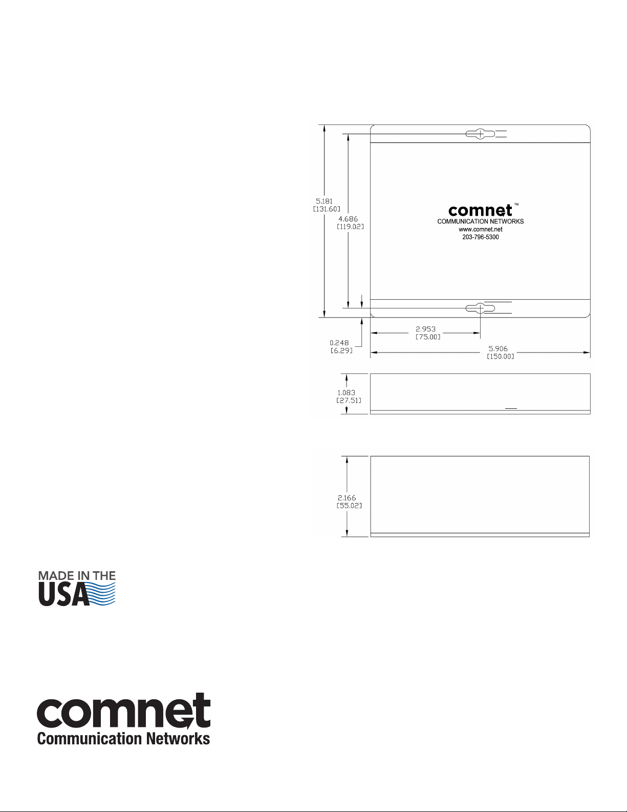
FIGURE A
Dimensions are for a standard ComNet™ module
.156 [3.96 mm]
.313 [7.95 mm]
IMPORTANT SAFEGUARDS:
A) Elevated Operating Ambient - If installed in a closed or multi-unit rack
assembly, the operating ambient temperature of the rack environment may
be greater than room ambient. Therefore, consideration should be given to
installing the equipment in an environment compatible with the maximum
ambient temperature (Tma) specified by the manufacturer.
B) Reduced Air Flow - Installation of the equipment in a rack should be such
that the amount of air flow required for safe operation of the equipment is not
compromised.
One Slot Module
(Transmitter)
Two Slot Module
(Receiver)
3 CORPORATE DRIVE | DANBURY, CT 06810 | USA
T: 203.796.5300 | F: 203.796.5303 | TECH SUPPORT: 1.888.678.9427 | INFO@COMNET.NET
8 TURNBERRY PARK ROAD | GILDERSOME | MORLEY | LEEDS, UK LS27 7LE
T: +44 (0)113 307 6400 | F: +44 (0)113 253 7462 | INFO-EUROPE@COMNET.NET
INS_FDC80_REV–
12/29/11
PAGE 7© 2014 Communications Networks Corporation. All Right s Reserved. “ComNet ” and the “ComNet Logo” are regis tered trademarks of Communic ation Networks, LLC.
 Loading...