

Page 1
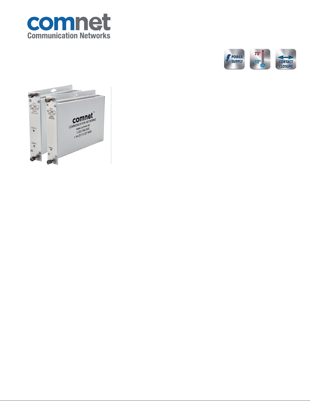
Fiber Optic Cable Breakage Monitor/Detector
FDC1 / FDC2
HARDENEDINCLUDED
The ComNet™ FDC1 single-channel and FDC2 dual-channel modems are designed
to detect and report a breakage or the loss of optical signal in either multimode or
single-mode fiber plants. Featuring a self-contained transmitter and receiver, these
units provide an optical output that is transmitted continuously through a customerfurnished fiber loop, where it returns to the internal receiver section. Should the
optical path be lost through a deliberate or unintentional breakage of the fiber, relay
contacts in the modem immediately change their state and report the loss of optical
signal. These contacts are user-configurable as either normally open (NO) or normally
closed (NC), and may be utilized for either a local or remote indication of cable plant
tampering, damage, or failure. The dual-channel version contains two independent
transmitter and receiver units in one compact package, and is ideal for continuously
monitoring the optical status of two separate fiber loops. Plug-and-play design ensures
ease of operation, and no optical or electrical adjustments are ever required.
1 OR 2
FEATURES
› One or two fiber loop units available
› Instantaneously reports optical fiber breakage or damage
locally or remotely
› Dry relay contacts may be configured for NO or NC operation
› Automatic resettable solid state current limiters for
unconditional modem protection
› Voltage transient protection on all power and signal input/
output lines provides protection from power surges and other
voltage transient events.
› Ambient operating temperature range: -40˚ C to +75˚ C for
deployment in virtually any unconditioned out-of-plant or
roadside environment
› Bi-color (Red/Green) status indicating LEDs provide rapid
indication of critical operating parameters
› Hot-swappable rack modules
› Interchangeable between stand-alone or rack mount use –
ComFit
› May be DIN-rail mounted by the addition of ComNet DIN-Rail
adaptor plate (Model DINBKT1 or DINBKT4, sold separately)
› Lifetime warranty
APPLICATIONS
› Fencing and Perimeter Surveillance: Optical fiber woven into
fencing or other structures
› Solar Panel/Photovoltaic Array (PVA) Theft Protection
› Protection of High-Value Assets and Facilities
› Continuous Status/Continuity Monitoring of Mission-Critical
Fiber Optic Trunk Cables
LIFETIME WARRANTY WWW.COMNET.NET TECH SUPPORT: 1.888.678.9427
Page 2
FDC1 / FDC2
SPECIFICATIONS
Fiber Optic Cable Breakage Monitor/Detector
Contacts
Contact Interface Response Time: 0.5 msec
Output Relay, 30VDC @ 0.5 A Contact Rating
Connectors
Power Terminal Block
Optical LC or SC (SFP dependent)
Ethernet RJ45
Contact Closure Terminal Block
1
Wavelength 1300 nm, Multimode or Single Mode
Number of Fibers 1 per loop
Connectors
Optical ST
Contact and Power Terminal Block
Electrical & Mechanical
Number of Rack Slots 1
Current Protection Automatic Resettable
Solid-State Current Limiters
Circuit Board Meets IPC Standard
Size 6.1 × 5.3 × 1.1 in (15.5 × 13.5 × 2.8 cm)
Shipping Weight <2 lb./0.9 kg
Environmental
MTBF >100,000 hours
Operating Temp -40˚ C to +75˚ C
Storage Temp -40˚ C to +85˚ C
Relative Humidity 0% to 95% (non-condensing)¹
Indicating LEDs Fiber Continuity, each channel
Power
Operating Voltage Range 8 to 27 VDC
Power Consumption 1W
Rack From Rack Power Supply
ORDERING INFORMATION
Fibers
Part Number Description
FDC 1M Single Channel Fiber Break Detector 1 per loop Multimode 62.5/125µm 12 dB 12 km (7.5 mi) 1
FDC2M Dual Channel Fiber Break Detector 2, 1 per loop Multimode 62.5/125µm 12 dB 12 km (7.5 mi) 1
FDC 1S Single Channel Fiber Break Detector 1 per loop Single Mode 9/125µm 12 dB 36 km (22.4 mi) 1
FDC2S Dual Channel Fiber Break Detector 2, 1 per loop Single Mode 9/125µm 12 dB 36 km (22.4 mi) 1
Accessories
Options
[2] Optical transmission distance is limited to optical loss of the fiber and any additional loss introduced by connectors, splices and patch panels.
Distance can also be limited by fiber bandwidth.
Complies with FDA Performance Standard for Laser Products, Title 21, Code of Federal Regulations, Subchapter J
In a continuing effort to improve and advance technology, product specifications are subject to change without notice.
DC Plug-in Power Supply, 90-264 VAC, 50/60 Hz (Included)
[1] Add suffix ‘/C’ for Conformally Coated Circuit Boards to extend to condensation conditions (Extra charge, consult factory)
DIN-Rail Mounting Adaptor Plate Kit – With mounting hardware (Optional, order model DINBKT1 or DINBK T4)
Required Fiber
Optical PWR
Budget
Maximum
Distance²
# Rack
Slots
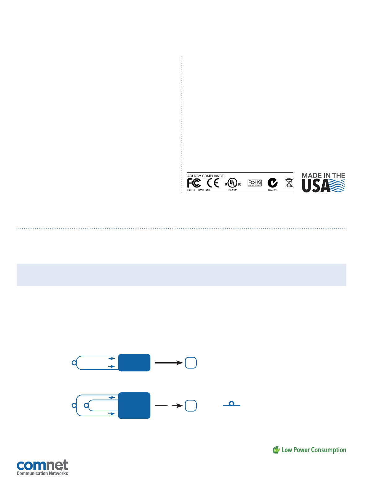
TYPICAL APPLICATION
TX
|
|
USA
C
C
T: 203.796.5300
|
T: +44 (0)113 307 6400
|
F: 203.796.5303
OPTICAL FIBER
|
|
FDC1
1 Fiber
Fiber Loop 2
Fiber Loop 1
3 CORPORATE DRIVE
8 TURNBERRY PARK ROAD
© 2014 Communic ation Netwo rks. All Righ ts Reserv ed. “ComNet ” and the “ComNe t Logo” are regi stered tra demarks of Com munication Ne tworks.
RX
TX
TX
FDC2
RX
RX
|
DANBURY, CONNECTICUT 06810
|
GILDERSOME
|
MORLEY
2
|
LEEDS, UK LS27 7LE
TECH SUPPORT: 1.888.678.9427
F: +44 (0)113 253 7462
|
INFO-EUROPE@COMNET.NET
|
INFO@COMNET.NET
 Loading...