

Page 1

INSTALLATION AND OPERATION MANUAL
FDC24NL[SFP] Series
24-CHANNEL DUPLEX CONTACT CLOSURE TRANSCEIVER
This manual serves the following
ComNet Model Numbers:
FDC24NL
FDC24NLSFP
The ComNet FDC24NL Series contact closure transceiver units provide transmission
of up to twenty four independent duplex dry switch or relay contact closures using
a single SFP optical port or any four-wire RS-422 copper circuit. The FDC24NL Series
supports an integrated field expandable RS-422 data bus allowing up to 12 uniquely
addressed units to be connected to the bus providing up to 288 unique duplex
contact closures over a single SFP optical port or RS-422 copper circuit.
The contact closure information is sent in packets that are ordered and encoded,
ensuring extremely robust transmission. Packets that are garbled, packets out of
sequence, and transmission bit errors will not cause random changes of state on
the contact relays. One relay can be optionally re-purposed as a summary fault
alarm contact and is triggered in the event that the unit loses fiber or RS-422 bus
communications. The FDC24NL series is offered with non-latching solid state relays.
Each module incorporates link and individual status indicating LEDs for monitoring
confirmation of contact closure input and output of each of the twenty four channels.
Packaged in the exclusive ComNet ComFit housing, these units may be either wall
or rack-mounted, or may be DIN-rail mounted by the addition of ComNet model
DINBKT1 or DINBKT4 adaptor plate.
INS_FDC24NL[SFP]_REV–
12/29/11
PAGE 1
Page 2
INSTALLATION AND OPERATION MANUAL FDC24NL[SFP] SERIES
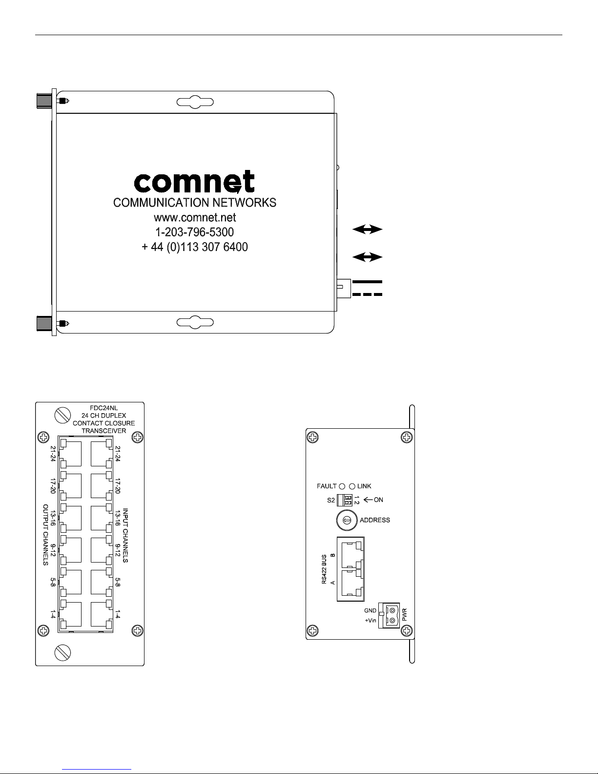
FIGURE 1 – FDC24NL RS-422 TRANSCEIVER
RS-422 4-Wire (B)
RS-422 4-Wire (A)
BLACK
BLACK WITH WHITE STRIPE
Power Supply:
Surface Mount: 8-15 VDC @ 5 W Max
Rack Mount: From Rack
NOTE: Remove Electrical Connector for
Rack Mount Units
FIGURE 2 – FDC24NL FRONT PANEL FIGURE 3 – FDC24NL REAR PANEL
TECH SUPPORT: 1.888.678.9427
INS_FDC24NL[SFP]_REV–
12/29/11
PAGE 2
Page 3
INSTALLATION AND OPERATION MANUAL FDC24NL[SFP] SERIES
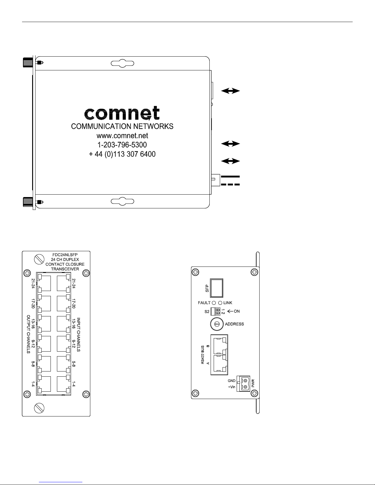
FIGURE 4 – FDC24NLSFP RS-422 & SFP TRANSCEIVER
SFP Slot (100FX Compatible Only)
RS-422 4-Wire (B)
RS-422 4-Wire (A)
BLACK
BLACK WITH WHITE STRIPE
Power Supply:
Surface Mount: 8-15 VDC @ 5 W Max
Rack Mount: From Rack
NOTE: Remove Electrical Connector for
Rack Mount Units
FIGURE 5 – FDC24NLSFP FRONT PANEL FIGURE 6 – FDC24NLSFP REAR PANEL
TECH SUPPORT: 1.888.678.9427
INS_FDC24NL[SFP]_REV–
12/29/11
PAGE 3
Page 4

INSTALLATION AND OPERATION MANUAL FDC24NL[SFP] SERIES
FIGURE 7 – CONTACT CLOSURE PIN-OUT
RJ-45 PORTS
The ports are located on the front panel of each unit
VIEW INSIDE RJ-45 PORT
RJ-45 BREAK-OUT KIT (SOLD SEPARATELY)
Screw Number Corresponds to RJ-45 Port Pin Number
CONTACT INPUT PORT
PIN # Wire Color Connections Polarity
1 Blue IN 1,5,9,13,17,21 +
2 Orange IN 1,5,9,13,17,21 –
3 Black IN 2,6,10,14,18,22 +
4 Red IN 2,6,10,14,18,22 –
5 Green IN 3,7,11,15,19,23 +
6 Yellow IN 3,7,11,15,19,23 –
7 Brown IN 4,8,12,16,20,24 +
8 White IN 4,8,12,16,20,24 –
CONTACT OUTPUT PORT
PIN # Wire Color Connections Polarity
1 Blue OUT 1,5,9,13,17,21 +
2 Orange OUT 1,5,9,13,17,21 –
3 Black OUT 2,6,10,14,18,22 +
4 Red OUT 2,6,10,14,18,22 –
5 Green OUT 3,7,11,15,19,23 +
6 Yellow OUT 3,7,11,15,19,23 –
7 Brown OUT 4,8,12,16,20,24 +
8 White OUT 4,8,12,16,20,24 –
Link Loss: The alarm inputs on one end are transferred to the outputs on the receiving end of the link. A closed contact
on the input causes a closed circuit on the opposing output (i.e., relay turned on). If the RS-422 serial data
link is broken or corrupt the outputs will remain in their last known good state.
Power-On State: At power-on all alarm outputs will be open (i.e. off), they will remain in this state until a valid link is
established, after which they will then track the inputs from units with the same address.
TECH SUPPORT: 1.888.678.9427
INS_FDC24NL[SFP]_REV–
12/29/11
PAGE 4
Page 5

INSTALLATION AND OPERATION MANUAL FDC24NL[SFP] SERIES
FIGURE 8 – RS-422 DATA PORTS RJ-45 PIN-OUT
The RS-422 RJ-45 data ports are designed to provide simple connection between units using a standard straight-through patch cable.
Connections should be made B to A. The units should always connect to a fiber device or FDC24NLSFP model using Port B.
RJ-45 PORTS
The ports are located on the rear panel of each unit
VIEW INSIDE RJ-45 PORT
RJ-45 BREAK-OUT KIT (SOLD SEPARATELY)
Screw Number Corresponds to RJ-45 Port Pin Number
RS-422 A PORT
PIN # Wire Color Connections Polarity
1 Blue DATA OUT –
2 Orange DATA OUT +
3 Black DATA IN +
4 Red NC
5 Green NC
6 Yellow DATA IN –
7 Brown NC
8 White NC
NC = No Connection
RS-422 B PORT
PIN # Wire Color Connections Polarity
1 Blue DATA IN –
2 Orange DATA IN +
3 Black DATA OUT +
4 Red NC
5 Green NC
6 Yellow DATA OUT –
7 Brown NC
8 White NC
NC = No Connection
FIGURE 9 – ADDRESS SWITCH SETTINGS
The switch is located on the rear panel of each unit
SW # Address
0 Reserved
1 UNIT 1
2 UNIT 2
3 UNIT 3
4 UNIT 4
5 UNIT 5
6 UNIT 6
7 UNIT 7
Up to 12 unique addresses are possible within a single system. Only contact information from units with the same address is
exchanged. Multiple units can exist with the same unit address in which case the contacts behave in an OR function so that an input
from any unit with the same address will trigger its corresponding output on as many units that have a matching address.
Please refer to Figure 12 for example system topologies.
TECH SUPPORT: 1.888.678.9427
SW # Address
8 UNIT 8
9 UNIT 9
A UNIT 10
B UNIT 11
C UNIT 12
D Not Used
E Not Used
F Not Used
INS_FDC24NL[SFP]_REV–
12/29/11
PAGE 5
Page 6

INSTALLATION AND OPERATION MANUAL FDC24NL[SFP] SERIES
FIGURE 10 – SWITCH SETTINGS
The switch is located on the rear panel of each unit.
S2-1 - Relay 24 Fault Summary Enable
S2-2 - Fault Summary Relay Operation
The switch S2 is used to configure the summary fault alarm relay operation. The operation is outlined below:
S2-1-ON: Relay Output 24 will function as a summary fault alarm which will trigger on loss of RS-422 or SFP link
S2-1-OFF: Relay Output 24 will function as a normal relay and will be triggered based on the input of contact 24 on a unit with the
same address.
S2-2-ON: The summary fault alarm relay will be normally closed and will go open circuit during an alarm condition.
S2-2-OFF: The summary fault alarm relay will be normally open and will close during an alarm condition.
FIGURE 11 – LED INDICATORS
FAULT LINK RS-422 BUS A RS-422 BUS B CONTACT CLOSURE
YELLOW – – – Flashing: Waiting for Link The yellow LED blinks in a repetitive
pattern to indicate the status of each of
the four contact inputs or outputs for that
port.
1 Blink: Contact 1,5,9,13,17,21
2 Blinks: Contact 2,6,10,14,18,22
3 Blinks: Contact 3,7,11,15,19,23
4 Blinks: Contact 4,8,12,16,20,24
GREEN Valid Address Selected Data Link Established RS-422 Link Established
OFF: No Link
RED Invalid Address
Selected
OFF Unit Powered Down Unit Powered Down – – –
No Fiber Connection
or No Mating FDC24
Connected
– – –
RS-422 Link Established
OFF: No Link
Following each blink pattern of the
yellow LED, the green LED will be on if
that contact is closed or off if that contact
is currently open.
ON: Contact Closed
OFF: Contact Open
TECH SUPPORT: 1.888.678.9427
INS_FDC24NL[SFP]_REV–
12/29/11
PAGE 6
Page 7

INSTALLATION AND OPERATION MANUAL FDC24NL[SFP] SERIES
FIGURE 12 – TYPICAL APPLICATIONS
Point-to-Point SFP Fiber Link
24 Contac ts IN 24 Contac ts IN
24 Contac ts OUT 24 Contacts OUT
FDC24NLSFP
Address 1
RS422 Bus With SFP Fiber Link
LEFT
24 Contac ts IN
24 Contac ts OUT
From Add ress 1 – Right
24 Contac ts IN
24 Contac ts OUT
From Add ress 2 – Right
FDC24NLSFP
Address 1
FDC24NL
Address 2
A
B
A
A
B
A
FDC24NLSFP
Address 1
RIGHT
FDC24NLSFP
Address 1
FDC24NL
Address 2
Cat5 Straight Patch C able
Fiber Opt ic Cable
24 Contac ts IN
24 Contac ts OUT
From Add ress 1 – Lef t
24 Contac ts IN
24 Contac ts OUT
From Add ress 2 – Lef t
24 Contac ts IN
24 Contac ts OUT
From Add ress 3 – Right
24 Contac ts IN
24 Contac ts OUT
From Add ress 4 – Right
FDC24NL
Address 3
FDC24NL
Address 4
B
A
B
Max 12 Uniquely
Address Units
Max 12 Uniquely
Address Units
B
A
B
FDC24NL
Address 3
FDC24NL
Address 4
24 Contac ts IN
24 Contac ts OUT
From Add ress 3 – Lef t
24 Contac ts IN
24 Contac ts OUT
From Add ress 4 – Lef t
TECH SUPPORT: 1.888.678.9427
INS_FDC24NL[SFP]_REV–
12/29/11
PAGE 7
Page 8

INSTALLATION AND OPERATION MANUAL FDC24NL[SFP] SERIES
FIGURE 12 – TYPICAL APPLICATIONS (CONT’D)
RS422 Bus With Standard Fiber Units
LEFT
FVT10D2I1C4E
Any ComN et fiber unit w/
an RS422 data channel
24 Contac ts IN
24 Contac ts OUT
From Add ress 1 – Right
24 Contac ts IN
24 Contac ts OUT
From Add ress 2 – Right
24 Contac ts IN
24 Contac ts OUT
From Add ress 3 – Right
FDC24NL
Address 1
FDC24NL
Address 2
FDC24NL
Address 3
B
A
B
A
B
RIGHT
FVR10D2I1C4E
Any ComN et fiber unit w/
an RS422 data channel
B
A
B
A
B
FDC24NL
Address 1
FDC24NL
Address 2
FDC24NL
Address 3
Cat5 Straight Patch C able
Fiber Opt ic Cable
24 Contac ts IN
24 Contac ts OUT
From Add ress 1 – Lef t
24 Contac ts IN
24 Contac ts OUT
From Add ress 2 – Lef t
24 Contac ts IN
24 Contac ts OUT
From Add ress 3 – Lef t
Multiple Units With The Same Address
LEFT
24 Contac ts IN
24 Contac ts OUT
From Add ress 1 – Right
24 Contac ts IN
24 Contac ts OUT
From Add ress 1 – Right
Contact inputs on the left side will be logic OR’ed together as both units have the same address. (e.g. closing input 1 on either unit will cause relay output 1 to close on the unit(s) with
address 1 on the right side of the system.)
In addition, the relay outputs on both unit s on the left side will close when the corresponding input is closed on the unit(s) with address 1 on the right side of the system.
FDC24NLSFP
Address 1
FDC24NL
Address 1
A
B
RIGHT
FDC24NLSFP
Address 1
24 Contac ts IN
24 Contac ts OUT
From Add ress 1 – Lef t
TECH SUPPORT: 1.888.678.9427
INS_FDC24NL[SFP]_REV–
12/29/11
PAGE 8
Page 9

MECHANICAL INSTALLATION INSTRUCTIONS
INSTALLATION CONSIDERATIONS
This fiber-optic link is supplied as a Standalone/Rack module. Units
should be installed in dry locations protected from extremes of
temperature and humidity.
C1-US, C1-EU, C1-AU OR C1-CH CARD CAGE RACKS
CAUTION: Although the units are hot-swappable and may be installed
without turning power off to the rack, ComNet recommends that
the power supply be turned off and that the rack power supply is
disconnected from any power source.
1. Make sure that the card is oriented right side up, and slide it into the
card guides in the rack until the edge connector at the back of the
card seats in the corresponding slot in the rack’s connector panel.
Seating may require thumb pressure on the top and bottom of the
card’s front panel.
CAUTION: Take care not to press on any of the LEDs.
2. Tighten the two thumb screws on the card until the front panel of the
card is seated against the front of the rack.
WARNING: Unit is to be used with a Listed Class 2 power supply.
FIGURE A
Dimensions are for a standard ComNet two-slot module
.156 [3.96 mm]
.313 [7.95 mm]
IMPORTANT SAFEGUARDS:
A) Elevated Operating Ambient - If installed in a closed or multi-unit rack
assembly, the operating ambient temperature of the rack environment may
be greater than room ambient. Therefore, consideration should be given to
installing the equipment in an environment compatible with the maximum
ambient temperature (Tma) specified by the manufacturer.
B) Reduced Air Flow - Installation of the equipment in a rack should be such
that the amount of air flow required for safe operation of the equipment is not
compromised.
© 2018 Communications Networks Corporation. All Rights Reserved. “ComNet” and the “ComNet Logo” are register ed trademark s of Communication Networks, LLC.
3 CORPORATE DRIVE | DANBURY, CT 06810 | USA
T: 203.796.5300 | F: 203.796.5303 | TECH SUPPORT: 1.888.678.9427 | INFO@COMNET.NET
8 TURNBERRY PARK ROAD | GILDERSOME | MORLEY | LEEDS, UK LS27 7LE
T: +44 (0)113 307 6400 | F: +44 (0)113 253 7462 | INFO-EUROPE@COMNET.NET
INS_FDC24NL[SFP]_REV–
12/29/11
PAGE 9
 Loading...