

Page 1
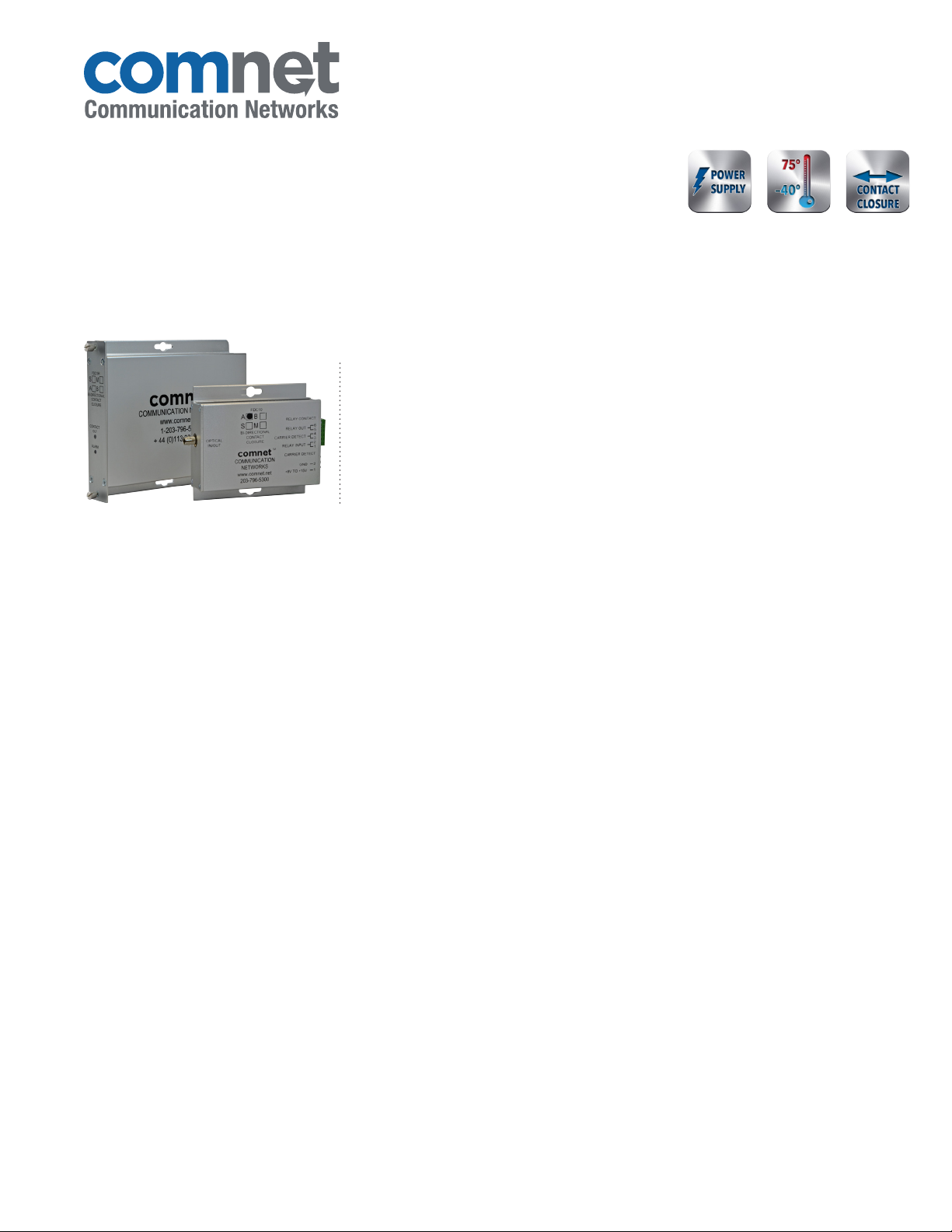
Bi-Directional Contact Closure Transceiver
FDC10 SERIES
HARDENEDINCLUDED
The ComNet™ FDC10 Series bi-directional contact closure transceiver provides
bi-directional transmission of contact closure over one multimode or single mode
optical fiber. The transceiver has a contact input and a 0.5 amp contact output. The
bi-directional contact closure module has two relay outputs and one relay input. One
relay output follows the “relay input” at the remote end. When the remote “relay input” is
shorted, the local relay output is closed and vice-versa. The second relay output is closed
when “carrier” is detected from the remote end, this indicates that the optical fiber is
connected and that the remote end has power and is operating.
1
FEATURES
› Transmits a single contact closure in one or two directions
› Distances up to 69 km (43 miles)
› 30 VDC, 0.5 amp relay output, normally open
› Point-to-Point transmission architecture
› Designed to meet full compliance with the environmental
requirements (ambient operating temperature, mechanical
shock, vibration, humidity with condensation, high-line/lowline voltage conditions and transient voltage protection) of
NEMA TS-1/TS-2 and the Caltrans Specification for Traffic
Signal Control Equipment.
› Plug-and-play design ensures ease of installation requiring no
electrical or optical adjustments.
› Relay contact for Carrier Detect (normally closed with carrier
present)
› Automatic resettable solid-state current limiters
› Voltage transient protection on all power and signal input/
output lines provides protection from power surges and other
voltage transient events.
› FDC10(M,S)1(A,B) models are housed in a smaller-sized
package for stand-alone mounting only, for use in those
applications where space may be limited
› FDC10R(M,S)1(A,B) ComFit models may be utilized as
a stand-alone package, or may be mounted within the
ComNet C1 Card Cage, and is fully hot-swappable
› Indicating LEDs are provided for confirming equipment
operating status. The relay position (open for RED and
closed for GREEN) is indicated by separate bi-color indicators
for each relay.
› Lifetime Warranty
APPLICATIONS
› Alarm Event Triggering
› Building Automation and Environmental Control Systems
› Fire and Alarm Systems
› Gate Control
› PIR Signal Transmission
› Traffic Signal Control Equipment
LIFETIME WARRANTY WWW.COMNET.NET TECH SUPPORT: 1.888.678.9427
Page 2
FDC10 SERIES
SPECIFICATIONS
Bi-Directional Contact Closure Transceiver
Contacts
Contact Inter face Response Time: 0.5 msec
Input Dry Contact Closure
Output SPST Relay, 30 VDC @ 0.5 A, Resistive loads only.
0.5 A Contact Rating - normally open
Wavelength A end = 1310/1550 nm
B end = 1550/1310 nm
Number of Fibers 1
Connectors
Optical ST
Contact and Power Terminal Block
LED Indicators Contact Relay
Carrier Detect
Electrical & Mechanical
Current Protection Automatic Resettable Solid-State Current Limiters
Circuit Board Meets IPC Standard
Size
ComFit 6.1 × 5.3 × 1.1 in (15.5 × 13.5 × 2.8 cm)
Surface Mount 4.0 × 3.7 × 1.0 in (10.4 × 9.5 × 2.7 cm)
Shipping Weight: <1 lb./0.5 kg
Environmental
MTBF >100,000 hours
Operating Temp -40˚ C to +75˚ C
Storage Temp -40˚ C to +85˚ C
Relative Humidity 0% to 95% (non-condensing)¹
Power
Operating Voltage Range 8 to 15 VDC
Power Consumption 2 W Max
ORDERING INFORMATION
Fibers
Part Number Description
FDC10M1A Small Size Contact Closure Transceiver (1310/1550 nm)
FDC 10M1B Small Size Contact Closure Transceiver (1550/1310 nm)
FDC10S1A Small Size Contact Closure Transceiver (1310/1550 nm)
FDC 10S1B Small Size Contact Closure Transceiver (1550/1310 nm)
FDC10RM1A ComFit Contact Closure Transceiver (1310/1550 nm)
FDC 10RM1B ComFit Contact Closure Transceiver (1550/1310 nm)
FDC10RS1A ComFit Contact Closure Transceiver (1310/1550 nm)
FDC 10RS1B ComFit Contact Closure Transceiver (1550/1310 nm)
Accessories
Options
[2] Optical transmission distance is limited to optical loss of the fiber and any additional loss introduced by connectors, splices and patch panels.
Distance can also be limited by fiber bandwidth.
NOTE: Complies with FDA Performance Standard for Laser Products, Title 21, Code of Federal Regulations, Subchapter J
In a continuing effort to improve and advance technology, product specifications are subject to change without notice.
DC Plug-in Power Supply, 90-264 VAC, 50/60 Hz (Included)
[1] Add suffix ‘/C’ for Conformally Coated Circuit Boards to extend to condensation conditions (Extra charge, consult factory)
Required Fiber
1
1
1
1
Multimode
62. 5/125µm
Single Mode
9/125µm
Multimode
62. 5/125µm
Single Mode
9/125µm
Optical PWR
Budget
16 dB 16 km (10 miles) NA
23 dB 69 km (43 miles) NA
16 dB 16 km (10 miles) 1
23 dB 69 km (43 miles) 1
Maximum
Distance²
# Rack
Slots
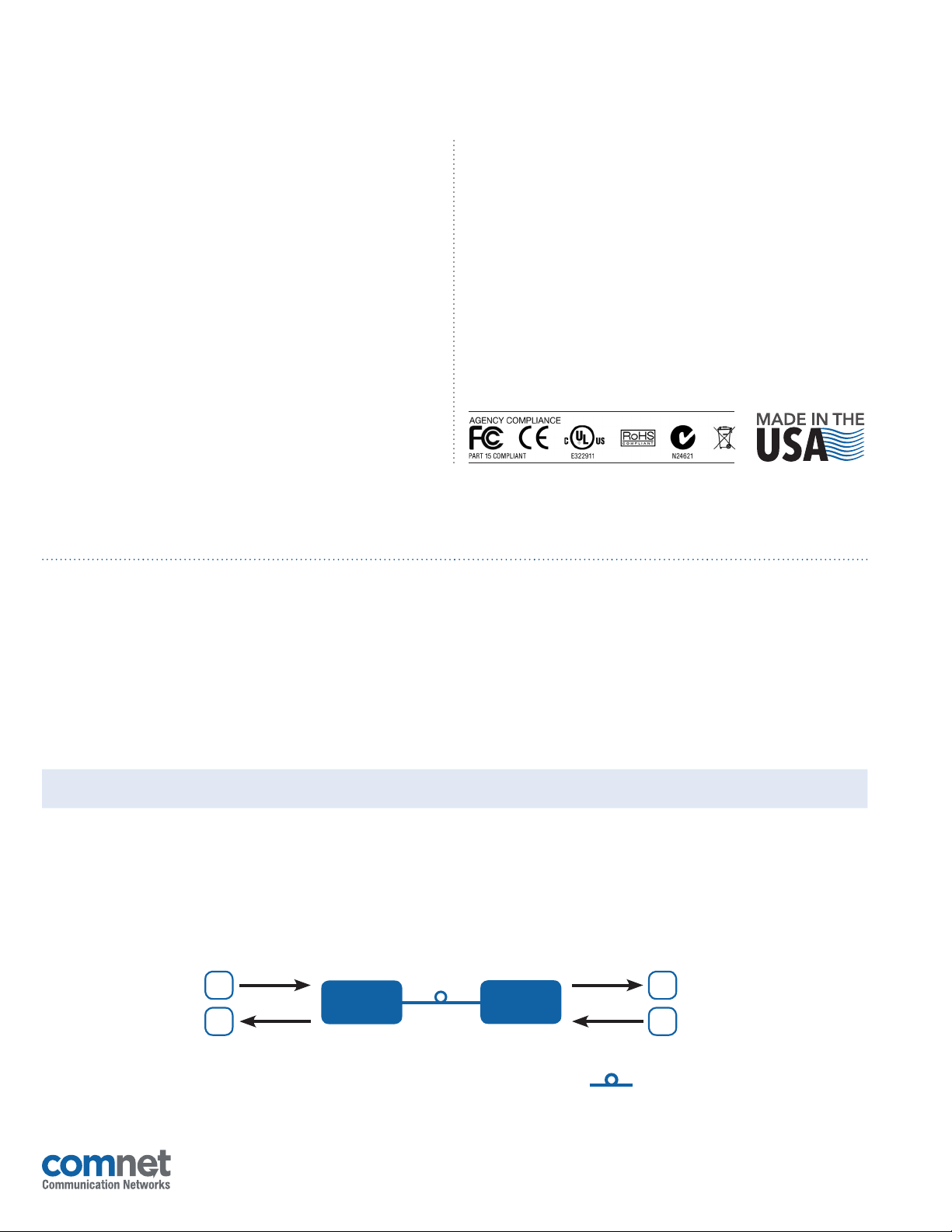
TYPICAL APPLICATION
C
C
3 CORPORATE DRIVE
8 TURNBERRY PARK ROAD
FDC10S1A
|
DANBURY, CONNECTICUT 06810
|
GILDERSOME
|
MORLEY
1 Fiber
9/125µm SM
Up to 69 km
(43 miles)
|
|
USA
T: 203.796.5300
|
LEEDS, UK LS27 7LE
FDC10S1B
|
F: 203.796.5303
|
T: +44 (0)113 307 6400
C
C
OPTICAL FIBER
|
TECH SUPPORT: 1.888.678.9427
|
F: +44 (0)113 253 7462
|
INFO-EUROPE@COMNET.NET
|
INFO@COMNET.NET
20 Nov 2014© 2014 Communic ation Netwo rks. All Righ ts Reserv ed. “ComNet ” and the “ComNe t Logo” are regi stered tra demarks of Com munication Ne tworks.
 Loading...