

Page 1

INSTALLATION AND OPERATION MANUAL
FDC10 Series
BI-DIRECTIONAL CONTACT CLOSURE TRANSCEIVER
This manual serves the following
ComNet Model Numbers:
FD C10 M1A
FD C10 M1B
FD C10 S1A
FD C10 S1B
FD C10 RM1A
FD C10 RM1B
FD C10 RS1A
FD C10 RS1B
The ComNet FDC10 Series bi-directional contact closure transceiver provides
bi-directional transmission of contact closure over one multimode or single mode
optical fiber. The transceiver has a contact input and a 0.5 amp contact output for each
channel. The bi-directional contact closure module has two relay outputs and one relay
input. One relay output follows the “relay input” at the remote end. When the remote
“relay input” is shorted, the local relay output is closed and vice-versa. The second relay
output is closed when “carrier” is detected from the remote end, this indicates that the
optical fiber is connected and that the remote end has power and is operating.
See Figures 1 – 2 and A - B for complete installation information.
INS_FDC10_REV–
09/25/15
PAGE 1
Page 2
INSTALLATION AND OPERATION MANUAL FDC10 SERIES
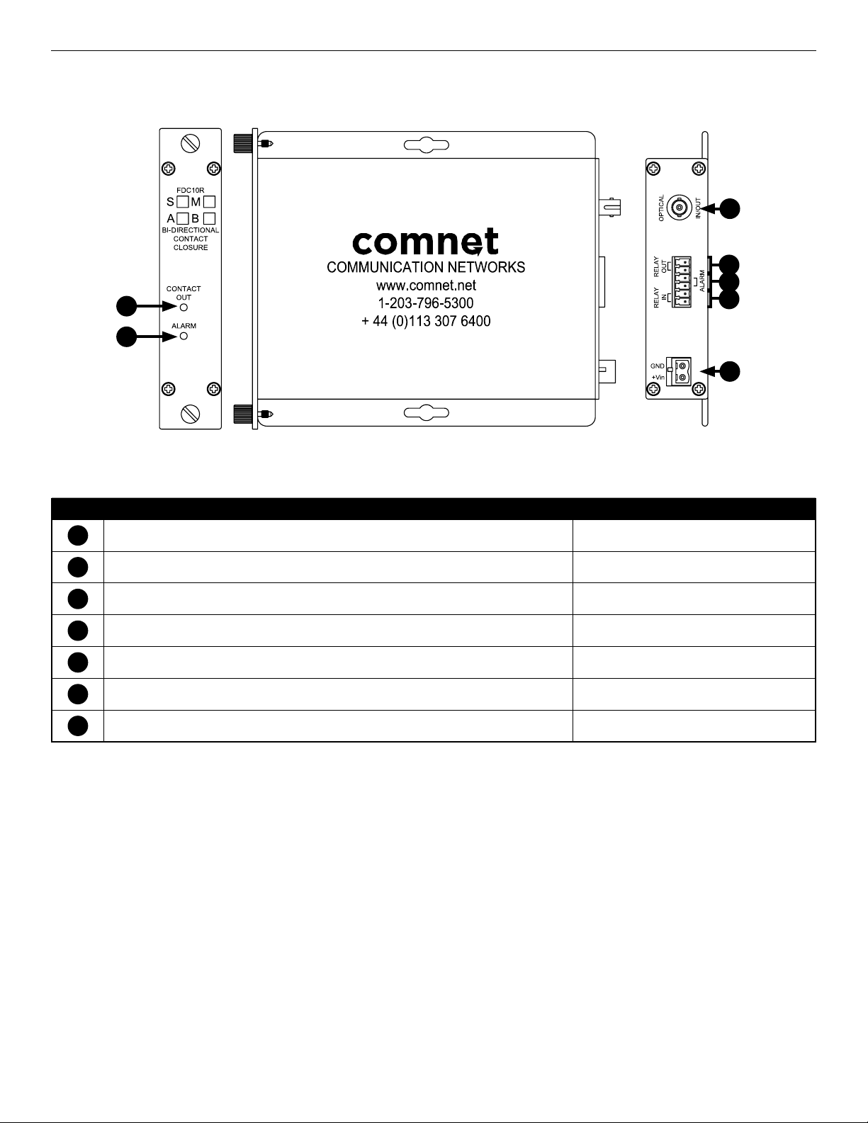
FIGURE 1 – Physical Features of FDC10R ComFit Unit
3
4
5
1
2
6
7
Table 1 – Physical Feature Descriptions
Call-out Description Manual Reference
1
Contact Out Indicating LED See Table 4 - Indicating LEDs
2
Alarm Condition Indicating LED See Table 4 - Indicating LEDs
3
Optical Fiber Connection
4
Normally Open (NO) Relay Output Pair
5
Normally Open (NO) Optical Link Alarm Relay
6
Dry Contact Closure Input Pair
7
Power Connections See Table 3 – Power Connections per Use Case
TECH SUPPORT: 1.888.678.9427
INS_FDC10_REV–
09/25/15
PAGE 2
Page 3

INSTALLATION AND OPERATION MANUAL FDC10 SERIES
FIGURE 2 – Physical Features of FDC10 Small Size Unit
2
4
1
3
Table 2 – Physical Feature Descriptions
Call-out Description Manual Reference
5
6
7
1
Optical Fiber Connection
2
Relay Contact Indicating LED See Table 4 - Indicating LEDs
3
Carrier Detect Indicating LED See Table 4 - Indicating LEDs
4
Normally Open (NO) Relay Output Pair
5
Normally Open (NO) Optical Link Alarm Relay
6
Dry Contact Closure Input Pair
7
Power Connections See Table 3 – Power Connections per Use Case
Table 3 – Power Connections per Use Case
FDC10R FDC10
Surface Mount 12 to 24 VDC 8 to 15 VDC
C1 Rack 9 VDC (Supplied by Rack, Remove Electrical Connector) NA
Table 4 – Indicating LEDs
CONTACT OUT / RELAY CONTACT ALARM / CARRIER DETECT
SOLID GREEN Closure detected on opposite end input pair
Optical Link is Good
SOLID RED No Closure detected on opposite end input pair OR Optical Link Failure Red Both Ends, Optical Link Failure (Relay Open)
OFF Power Not Applied Power Not Applied
TECH SUPPORT: 1.888.678.9427
Power Applied
Good Optical Link (Relay Closed)
INS_FDC10_REV–
09/25/15
PAGE 3
Page 4

INSTALLATION AND OPERATION MANUAL FDC10 SERIES
INSTALLATION CONSIDERATIONS
The FDC10R is supplied as a ComFit Standalone / Rack module.
The FDC10 is supplied as a Standalone / Surface Mount module.
Units should be installed in dry locations protected from extremes of
temperature and humidity.
CAUTION: Take care not to press on any of the LEDs.
2. Tighten the two thumb screws on the card until the front panel of the
card is seated against the front of the rack.
19 INCH RACK-MOUNTABLE CARD CAGES
CAUTION: Although the units are hot-swappable and may be installed
without turning power off to the rack, ComNet recommends that the
power supply be turned off and that the rack power supply is disconnected
from any power source.
Note: Remove electrical connector before installing in card cage rack.
1. Make sure that the card is oriented right side up, and slide it into the card
guides in the rack until the edge connector at the back of the card seats in
the corresponding slot in the rack’s connector panel. Seating may require
thumb pressure on the top and bottom of the card’s front panel.
FIGURE A
Dimensions are for a standard ComNet ComFit one slot module
IMPORTANT SAFEGUARDS:
A) Elevated Operating Ambient - If installed in a closed or multi-unit rack
assembly, the operating ambient temperature of the rack environment may
be greater than room ambient. Therefore, consideration should be given to
installing the equipment in an environment compatible with the maximum
ambient temperature (Tma) specified by the manufacturer.
B) Reduced Air Flow - Installation of the equipment in a rack should be such
that the amount of air flow required for safe operation of the equipment is not
compromised.
FIGURE B
Dimensions are for a small size ComNet surface mount module
3 CORPORATE DRIVE | DANBURY, CT 06810 | USA
T: 203.796.5300 | F: 203.796.5303 | TECH SUPPORT: 1.888.678.9427 | INFO@COMNET.NET
8 TURNBERRY PARK ROAD | GILDERSOME | MORLEY | LEEDS, UK LS27 7LE
T: +44 (0)113 307 6400 | F: +44 (0)113 253 7462 | INFO-EUROPE@COMNET.NET
© 2015 Communications Networks Corporation. All Right s Reserved. “ComNet” and the “ComNet Lo go” are registered trademarks of Communication Networ ks, LLC.
INS_FDC10_REV–
09/25/15
PAGE 4
 Loading...