

Page 1
QUICK START GUIDE
FDW1000 / EXP101
OPTICAL WIEGAND, MAGSTRIPE & F/2F DATA
EXTENDER AND EXPANSION MODULE
This guide serves the following
ComNet Model Numbers:
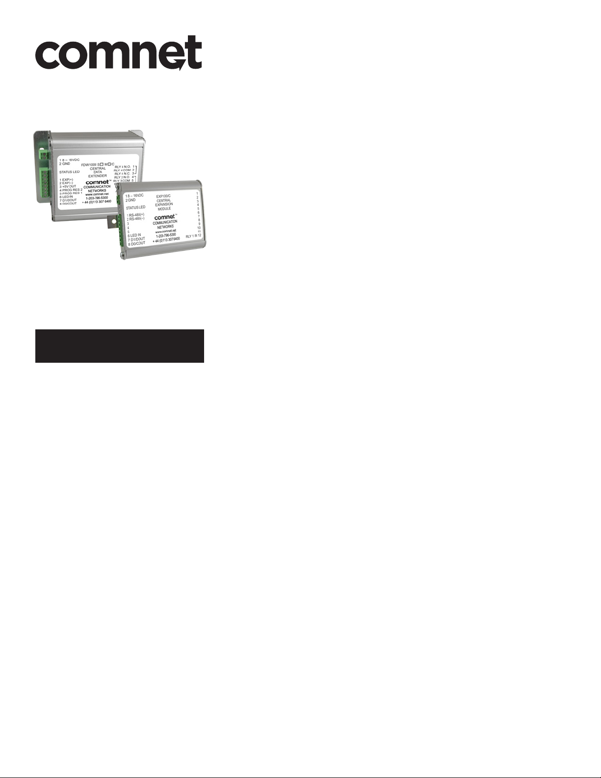
FDW1000M/C
FDW1000M/R
FDW1000S/C
FDW1000S/R
EXP101/C
EXP101/R
The ComNet FDW1000 Series and EXP101 Series of transceivers makes it possible to
install card readers farther from the access control panel by providing a long-range
fiber optic connection between the door or gate readers and most manufacturers’
access control panels. The series includes both a remote (door/gate) device and a
central (access control panel) device. The FDW1000 devices are compatible with the
EXP101 expansion modules that allow up to seven additional readers to share the
optical link created by the FDW1000/C (central) and FDW1000/R (remote) devices.
QSG_FDW1000_EXP101 01/06/2020
Page 2

QUICK START GUIDE FDW1000 / EXP101
Contents
General Information – FDW1000 and EXP101 Series 3
Device description 3
Items in this series 3
Specifications 4
Power 4
Inputs and outputs 4
Contact closure (relay) channels 4
Preparation 5
Tools 5
Before beginning 5
Configuration 6
Configuring an FDW1000 – current version – (rev .3xx range) 6
Configuring an EXP101 – current version – (rev .4xx range) 8
Wiring and Wiring Examples 9
Recommendations for new wire installation 9
Typical wiring diagrams 10
References 15
LED status 15
AutoCAD drawings 16
TECH SUPPORT: 1.888.678.9427 / +44 (0)203 630 1653
QSG_FDW1000_EXP101 01/06/2020 PAGE 2
Page 3

QUICK START GUIDE FDW1000 / EXP101
General Information – FDW1000 and EXP101 Series
Device description
The ComNet FDW1000 Series and EXP101 Series of transceivers makes it possible to install
card readers farther from the access control panel by providing a long-range fiber optic connection between the door or gate readers and most manufacturers’ access control panels. The
series includes both a remote (door/gate) device and a central (access control panel) device. The
FDW1000 devices are compatible with the EXP101 expansion modules that allow up to seven
additional readers to share the optical link created by the FDW1000/C (central) and FDW1000/R
(remote) devices.
Items in this series
FDW1000M/C – Wiegand transceiver, central side, multimode
FDW1000M/R – Wiegand transceiver, remote side, multimode
FDW1000S/C – Wiegand transceiver, central side, singlemode
FDW1000S/R – Wiegand transceiver, remote side, singlemode
EXP101/C – expansion module, central side
EXP101/R – expansion module, remote side
TECH SUPPORT: 1.888.678.9427 / +44 (0)203 630 1653
QSG_FDW1000_EXP101 01/06/2020 PAGE 3
Page 4

QUICK START GUIDE FDW1000 / EXP101
Specifications
The following specifications apply to all of the items in this series
Power
• operating voltage range = DC 8 to 12 V
• power consumption < 6 W each
• hardened power supply item number PS-AMR5-12 as needed
Inputs and outputs
Data
• Wiegand (max 248 bits pass through, filter the first eight bits unless Wiegand No Filter is active)
• strobed (clock and data)
• F/2F unsupervised
LED
• DC 0 to 30 V
Contact closure (relay) channels
Relay Channels 1 and 2
• FDW1000/C and EXP101/C central units will each accept up to two dry contact closures as
inputs – RELAY 1 IN and RELAY 2 IN – and pass the status of each contact to corresponding
FDW1000/R and EXP101/R remote units, each containing two single-pole, double-throw relays
– RELAY 2 OUT and RELAY 2 OUT.
Relay Channels 3 and 4
• FDW1000/R and EXP101/R remote unit will each accept up to two dry contact closures as
inputs – RELAY 3 IN and RELAY 4 IN – and pass the status of each contact to corresponding
FDW1000/C and EXP101/C central units, each containiing two single-pole, double-throw relays
– RELAY 3 OUT and RELAY 4 OUT.
Relay Contact Ratings
• DC 30 V, 1.0 A, resistive loads only, 1 × 10⁵ operations at +room temperature (+20°C or+68°F)
• AC 125 V, 0.3 A, resistive loads only, 1 × 10⁵ operations at +room temperature (+20°C or+68°F)
TECH SUPPORT: 1.888.678.9427 / +44 (0)203 630 1653
QSG_FDW1000_EXP101 01/06/2020 PAGE 4
Page 5
QUICK START GUIDE FDW1000 / EXP101
Preparation
Tools
• #1 tip Phillips head screwdriver to remove metal covers
• small flat blade screwdriver to set the DIP switches
Before beginning
• determine the communications format for each reader;
• Wiegand with data words that are at least 8 bits (most readers), or;
• Wiegand with data words that are less than 8 bits (typical of reader / keypad combination units), or;
• unsupervised F/2F (Casi Rusco systems)
• determine the number of expansion module pairs – if any – that will be needed (this quantity
will be one less than the number of readers in the link);
• determine whether Relay 3 will be reserved to monitor the status of the optical link;
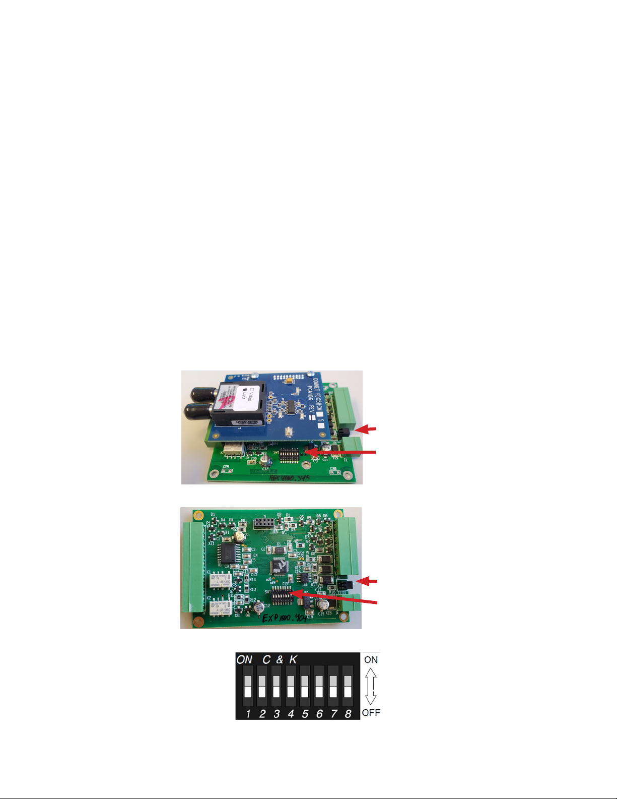
• locate the STATUS indicator LED (between the 2-pin power connector and the 8-pin terminal
strip – see Figures 1 and 2 below)
• with the cover removed, locate the eight DIP switches (OFF is toward the edge of the circuit
board and Switch 8 is closest to the power connector – see Figures 1, 2, and 3 below).
“S TAT US” LED
DIP switches
Figure 1 – FDW1000
“S TAT US” LED
DIP switches
Figure 3 – expanded view of DIP switches
TECH SUPPORT: 1.888.678.9427 / +44 (0)203 630 1653
Figure 2 – EXP101
QSG_FDW1000_EXP101 01/06/2020 PAGE 5
Page 6

QUICK START GUIDE FDW1000 / EXP101
Configuration
Configuring an FDW1000 – current version – (rev .3xx range)
Initialization
• Do not apply power to the FDW1000. Remove all fiber and signal connections. Remove the
metal housing to expose the DIP switches.
• Turn DIP Switches 1 and 4 ON, all others OFF.
• Using DIP Switches 6, 7, and 8, set the communications format using the following table:
Communications Format DIP Switch 6 DIP Switch 7 DIP Switch 8
not used during initialization OFF OFF OFF
Wiegand OFF OFF ON
Wiegand, no filter OFF ON OFF
strobed rising edge (MR-5) OFF ON ON
strobed rising edge (Dorado 644) ON OFF OFF
strobed rising edge (Mag-Tek) ON OFF ON
strobed falling edge ON ON OFF
unsupervised F/2F ON ON ON
• Apply power to the FDW1000.
• The STATUS indicator LED near the power connector should very quickly become solid green.
• If the STATUS indicator LED quickly becomes solid green, the unit is now initialized. Continue
to the Programming section below.
• If the STATUS indicator LED fails to quickly become solid green, repeat the steps above. If still
unsuccessful, consider the unit bad.
TECH SUPPORT: 1.888.678.9427 / +44 (0)203 630 1653
QSG_FDW1000_EXP101 01/06/2020 PAGE 6
Page 7

QUICK START GUIDE FDW1000 / EXP101
Programming
• Remove power from the FDW1000.
• Turn all DIP switches OFF.
• Continue to set Central / Remote (Switch 3), Supervision Relay Mode (Switch 4), Pull-Up Resistor
Mode (Switch 5), and number of EXP101 pairs (Switches 6, 7, and 8) using the following table:
DIP Switch Number DIP Switch Setting
1 – not used during programming OFF
2 – not used during programming OFF
3 – Central / Remote
4 – Supervision Relay
5 – Pull-Up Resistor
6, 7, and 8 – Number of EXP101
Pairs
OFF = Remote unit
ON = Central unit
OFF = disables supervision relay – allows Relay Channel 3 to operate as an independent
dry contact closure channel
ON = enables supervision relay – allows Relay Channel 3 to be used to monitor the status
of the optical link
OFF = disables pull-up resistor
ON = enables pull-up resistor (for copper paths > 200 ft or when using F/2F Casi Rusco 941)
OFF OFF OFF = no expansion modules
OFF OFF ON = one pair of expansion modules
OFF ON OFF = two pairs of expansion modules
OFF ON ON = three pairs of expansion modules
ON OFF OFF = four pairs of expansion modules
ON OFF ON = five pairs of expansion modules
ON ON OFF = six pairs of expansion modules
ON ON ON = seven pairs of expansion modules
• Apply power to the FDW1000. The device is now ready to use.
A common ground connection is critical for proper operation. At each remote location, a common
ground must exist between the reader(s), the FDW1000/R, and any EXP101/Rs. At the central location, a common ground must exist between the panel, the FDW1000/C, and any EXP101/Cs.
TECH SUPPORT: 1.888.678.9427 / +44 (0)203 630 1653
QSG_FDW1000_EXP101 01/06/2020 PAGE 7
Page 8

QUICK START GUIDE FDW1000 / EXP101
Configuring an EXP101 – current version – (rev .4xx range)
• Do not apply power to the EXP101. Remove all copper and signal connections. Remove the
metal housing to expose the DIP switches.
• Turn all DIP switches OFF.
• DIP Switch 1 on the EXP101 is used during factory testing but is not used during configuration
and should remain OFF.
• Using DIP Switch 2, set each unit as an EXP101/C (Central unit) or as an EXP101/R (Remote unit).
• Turn DIP Switch 2 ON to make the unit an EXP101/C (Central unit).
• Leave DIP Switch 2 OFF to make the unit an EXP101/R (Remote unit).
• Using DIP Switches 3, 4, and 5, set the communications format using the following table:
Communications Format DIP Switch 3 DIP Switch 4 DIP Switch 5
Not used OFF OFF OFF
Wiegand OFF OFF ON
Wiegand, no filter OFF ON OFF
strobed rising edge (MR-5) OFF ON ON
strobed rising edge (Dorado 644) ON OFF OFF
strobed rising edge (Mag-Tek) ON OFF ON
strobed falling edge ON ON OFF
unsupervised F/2F ON ON ON
• Using DIP Switches 6, 7, and 8, set the polling address of each pair of EXP101s using the table
below.
• If only one pair of EXP101s will be used, set the EXP101/C and the EXP101/R to polling address 1.
• If more than one pair of EXP101s will be used, set one pair of EXP101/C and EXP101/R to polling
address 1. Address the next pair using polling address 2 and continue sequentially as needed.
Number of EXP101 Pairs DIP Switch 6 DIP Switch 7 DIP Switch 8
Not used OFF OFF OFF
one pair of EXP101s – polling address 1 OFF OFF ON
two pairs of EXP101s – polling address 2 OFF ON OFF
three pairs of EXP101s – polling address 3 OFF ON ON
four pairs of EXP101s – polling address 4 ON OFF OFF
five pairs of EXP101s – polling address 5 ON OFF ON
six pairs of EXP101s – polling address 6 ON ON OFF
seven pairs of EXP101s – polling address 7 ON ON ON
• Apply power to the EXP101. The unit is now ready to use.
A common ground connection is critical for proper operation. At each remote location, a common
ground must exist between the reader(s), the FDW1000/R, and any EXP101/Rs. At the central location, a common ground must exist between the panel, the FDW1000/C, and any EXP101/Cs.
TECH SUPPORT: 1.888.678.9427 / +44 (0)203 630 1653
QSG_FDW1000_EXP101 01/06/2020 PAGE 8
Page 9

QUICK START GUIDE FDW1000 / EXP101
Wiring and Wiring Examples
Recommendations for new wire installation
Power
PVC - Belden 8461 - 18 AWG 1 pair, 25 feet max.
Plenum - Belden 82740 - 18 AWG 1 pair, 25 feet max.
Wiegand / LED
PVC - Belden 9942 or 8777 - 22 AWG 3 pair shielded, 250 feet max.
Plenum - Belden 82777 - 22 AWG 3 pair shielded, 250 feet max.
PVC - Belden 9873 - 20 AWG 3 pair shielded, 500 feet max.
Plenum - Belden 83606 or 85164 - 20 AWG 3 pair shielded, 500 feet max.
Inputs and Outputs
PVC - Belden 8451 - 22 AWG 1 pair, 1,000 feet max.
Plenum - Belden 82761 - 22 AWG 1 pair, 1,000 feet max.
RS-485
PVC - Belden 9744 - 22 AWG 2 twisted pair, 4,000 feet max.
Plenum - Belden 82741 - 22 AWG 2 twisted pair, 4,000 feet max.
TECH SUPPORT: 1.888.678.9427 / +44 (0)203 630 1653
QSG_FDW1000_EXP101 01/06/2020 PAGE 9
Page 10

QUICK START GUIDE FDW1000 / EXP101
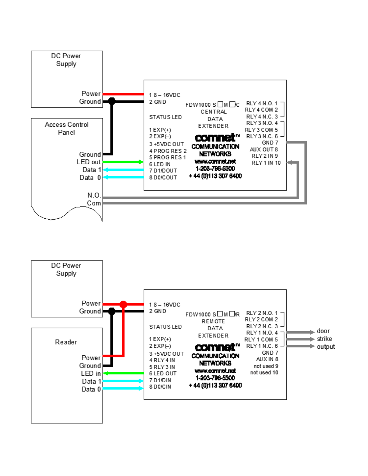
Typical wiring diagrams
The following diagrams show some typical wiring examples. For simplicity, each diagram shows
only the connections that are relavent to the diagram’s purpose.
Wiring common grounds
TECH SUPPORT: 1.888.678.9427 / +44 (0)203 630 1653
QSG_FDW1000_EXP101 01/06/2020 PAGE 10
Page 11
QUICK START GUIDE FDW1000 / EXP101
Door strike follows dry contact closure, one reader
TECH SUPPORT: 1.888.678.9427 / +44 (0)203 630 1653
QSG_FDW1000_EXP101 01/06/2020 PAGE 11
Page 12

QUICK START GUIDE FDW1000 / EXP101
Door strike follows LED, one reader
TECH SUPPORT: 1.888.678.9427 / +44 (0)203 630 1653
QSG_FDW1000_EXP101 01/06/2020 PAGE 12
Page 13

QUICK START GUIDE FDW1000 / EXP101
Door strike follows dry contact closure, two readers
TECH SUPPORT: 1.888.678.9427 / +44 (0)203 630 1653
QSG_FDW1000_EXP101 01/06/2020 PAGE 13
Page 14

QUICK START GUIDE FDW1000 / EXP101
Door strike follows LED, two readers
TECH SUPPORT: 1.888.678.9427 / +44 (0)203 630 1653
QSG_FDW1000_EXP101 01/06/2020 PAGE 14
Page 15

QUICK START GUIDE FDW1000 / EXP101
References
LED status
FDW1000s
• During initialization:
• A solid green STATUS LED on power up indicates that the unit has accepted the settings and
that it is ready to be programmed.
• After successful initialization and programming:
• An alternating green / red STATUS LED indicates that there is no optical link between the
FDW1000s.
• If using expansion modules, a solid green STATUS LED indicates a problem with at least one
expansion module connected to the FDW1000 at the opposite end.
• A rapidly flashing green STATUS LED indicates that there is communication between the Central
and the Remote units and – if using expansion modules – all expansions modules are operating
properly. The STATUS LED’s will flash green after each polling cycle. The frequency of the flashing
will depending on the number of expansion modules being used. With only one pair of FDW1000s
connected – no expansion modules – the STATUS LED should flash several times per second. With
seven sets of expansion modules, the STATUS LED could flash as slowly as one flash per second.
EXP101s
• Once a Central / Remote pair of FDW1000s and the pair(s) of EXP101s have been successfully
initialized and programmed:
• A STATUS LED-flashing green slowly indicates that there is no optical link between the FDW1000s.
• A solid red STATUS indicator LED indicates that the unit is properly powered but there is no
2-wire RS-485 link.
• A rapidly flashing green STATUS LED indicates that there is communication between the
Central and the Remote units and that there is a good 2-wire RS-485 link. The STATUS LED
will flash green after each polling cycle. The frequency of the flashing will depending on the
number of expansion modules being used. With only one pair of FDW1000s connected – no
expansion modules – the STATUS LED’s should flash several times per second. With seven sets
of expansion modules, the STATUS LED could flash as slowly as one flash per second.
LED Status
STAT US LE D
Off not properly powered not properly powered not properly powered
Green, solid ready to be programmed opposite side expansion module failure not used
Green, flashing slowly not used not used optical link failure
Green, flashing rapidly not used good optical link
Red, solid not used not used no 2-wire RS-485 link
Red, flashing not used not used not used
Red / Green, alternating not used optical link failure not used
(during initialization)
FDW
(initialized and programmed)
FDW
EX P101
(programmed)
good optical link and
good 2-wire RS-485 link
TECH SUPPORT: 1.888.678.9427 / +44 (0)203 630 1653
QSG_FDW1000_EXP101 01/06/2020 PAGE 15
Page 16

QUICK START GUIDE FDW1000 / EXP101
AutoCAD drawings
TECH SUPPORT: 1.888.678.9427 / +44 (0)203 630 1653
QSG_FDW1000_EXP101 01/06/2020 PAGE 16
Page 17

ComNet Customer Service
Customer Care is ComNet Technology’s global service center, where our
professional staff is ready to answer your questions at any time.
Email ComNet Global Service Center: customercare@comnet.net
3 CORPORATE DRIVE | DANBURY, CT 06810 | USA
T: 203.796.5300 | F: 203.796.5303 | TECH SUPPORT: 1.888.678.9427 | INFO@COMNET.NET
SUITE 4 - 2 TURNBERRY PARK ROAD | GILDERSOME | MORLEY | LEEDS, UK LS27 7LE
T: +44 (0)203 630 1652 | F: +44 (0)113 253 7462 | INFO-EUROPE@COMNET.NET
© 2020 Communications Networks Corporation. All Rights Reserved. “ComNet ” and the “ComNet Logo” are registered trademarks of Communication Net works, LLC.
QSG_FDW1000_EXP101 01/06/2020
 Loading...