

Page 1

INSTALLATION AND OPERATION MANUAL
INDUSTRIAL ETHERNET PRODUCTS MANAGEMENT UTILITY SUITE
eConsole is ComNet’s powerful software monitoring and diagnostic utility. eConsole
includes three separate utilities eCommander, eVision, and eMonitor. With the
eCommander application the user can set parameters for multiple switches at the
same time and it provides a powerful interface for users to manage all switches in the
network.
eConsole is not only a powerful utility for users to configure but also a useful suite
of utilities for monitoring. Users can monitor switches’ status via eMonitor. If the
monitored switches fail, the failure information will be displayed on the Host
monitoring interface.
The eVision application provides a real time overview of the entire network for visual
fault indication and full monitoring capabilities for SNMP based traps.
Rev. 11.5.14
Page 2

INSTALLATION AND OPERATION MANUAL ECONSOLE
Contents
Introduction 4
Regulatory Compliance Statement 4
Warranty 4
Disclaimer 4
System Requirements 5
Install eConsole 6
Configuring PC Network Interface Card 9
eCommander 10
Discover y 10
Task Menu 13
Settings Menu 14
Help 15
Icons Introduction 15
Devices list 16
LED and Port Status 16
Status Monitor 17
Scan Devices Configuration 18
Syslog Events 19
Wizards 19
Group IP Setting Wizard 19
Group Firmware Update Wizard 20
Group Configuration Backup 22
Group Configuration Restore 23
Group Redundant Ring Setting 24
TECH SUPPORT: 1.888.678.9427
INS_eConsole_REV– 12/20/12 PAGE 2
Page 3

INSTALLATION AND OPERATION MANUAL ECONSOLE
eVision 25
About eVision 25
Topology Wizard 25
System Menu Bar 29
File 29
Edit 30
Device Database Management 32
View 33
Layout 33
Management 34
Help 34
Tool Bar 35
General 35
Topology Management 36
Map Management 37
Device Tree & Group Tree 38
Topology 39
Map 41
System Log Area 42
eMonitor 43
Add device 43
System Bar 44
File 44
Tool 4 4
About 45
Function Bar 45
Group Tree 46
Monitor Area 47
TroubleShooting 48
TECH SUPPORT: 1.888.678.9427
INS_eConsole_REV– 12/20/12 PAGE 3
Page 4

INSTALLATION AND OPERATION MANUAL ECONSOLE
Introduction
Regulatory Compliance Statement
Product(s) associated with this publication complies/comply with all applicable regulations. Please
refer to the Technical Specifications section for more details.
Warranty
ComNet warrants that all ComNet products are free from defects in material and workmanship
for a specified warranty period from the invoice date for the life of the installation. ComNet will
repair or replace products found by ComNet to be defective within this warranty period, with
shipment expenses apportioned by ComNet and the distributor. This warranty does not cover
product modifications or repairs done by persons other than ComNet-approved personnel, and
this warranty does not apply to ComNet products that are misused, abused, improperly installed,
or damaged by accidents.
Please refer to the Technical Specifications section for the actual warranty period(s) of the
product(s) associated with this publication.
Disclaimer
Information in this publication is intended to be accurate. ComNet shall not be responsible for its
use or infringements on third-parties as a result of its use. There may occasionally be unintentional
errors on this publication. ComNet reserves the right to revise the contents of this publication
without notice.
TECH SUPPORT: 1.888.678.9427
INS_eConsole_REV– 12/20/12 PAGE 4
Page 5

INSTALLATION AND OPERATION MANUAL ECONSOLE
System Requirements
Minimum System Requirements
» Pentium(R) Dual-core 2.4 (or above)
» VGA Monitor with 1024 x 768 resolution (or above)
» 1 GB RAM (recommended 2GB and above)
» Java Runtime Environment 6 update 30 (or above)
» Internet Explorer 6.0 (or above)
» WinPcap 4.0 (or above)
Supported Network Protocols
» TCP / IP
» UDP
» SNMP
Operating System
» Windows 8
» Windows 7
» Windows Vista
» Windows XP/2000
» Windows Server 2008
» Windows Server 2003
Note: Please make sure your computer has Java Runtime Environment installed (if not, the
installer will ask if you would like to install it. You can also download the latest version of
Java Runtime Environment (JRE) 7 from SUN at http://java.com/en/download/)
TECH SUPPORT: 1.888.678.9427
INS_eConsole_REV– 12/20/12 PAGE 5
Page 6
INSTALLATION AND OPERATION MANUAL ECONSOLE
Install eConsole
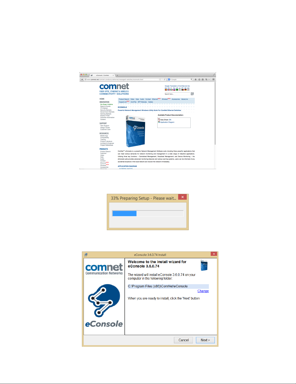
Please see the following instructions to install the eConsole software
Step 1 – Obtain the latest copy of eConsole from the product information CD that accompanied
your switch or by visiting the website at www.comnet.net
eConsole Product Page on ComNet’s Website
Step 2 – Click on the eConsole EXE file to start the installation.
Step 3 – Click Next to install eConsole in the default directory or click Change to change the path
of installation. Then click Next to continue.
TECH SUPPORT: 1.888.678.9427
INS_eConsole_REV– 12/20/12 PAGE 6
Page 7
INSTALLATION AND OPERATION MANUAL ECONSOLE
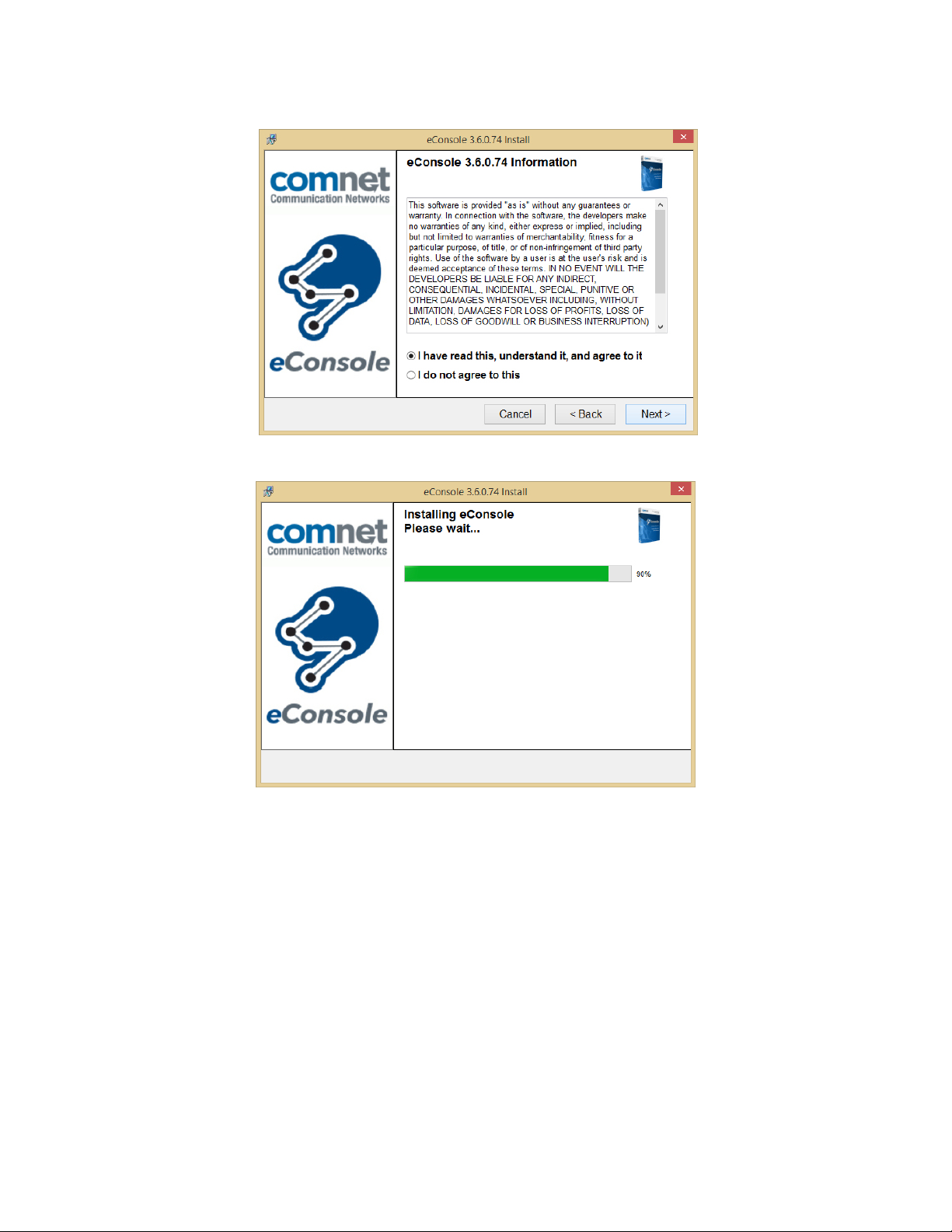
Step 4 – Accept the terms & conditions to continue with the install and click Next to continue.
Step 5 – The software will now be installed.
After the software has been installed new windows will pop up asking the user to install Java
runtime environment 7 update 51 and WinPcap 4.1.3 which are requirements for eConsole to run
properly. You can skip these installations if both of these programs are already installed on your
machine.
TECH SUPPORT: 1.888.678.9427
INS_eConsole_REV– 12/20/12 PAGE 7
Page 8
INSTALLATION AND OPERATION MANUAL ECONSOLE
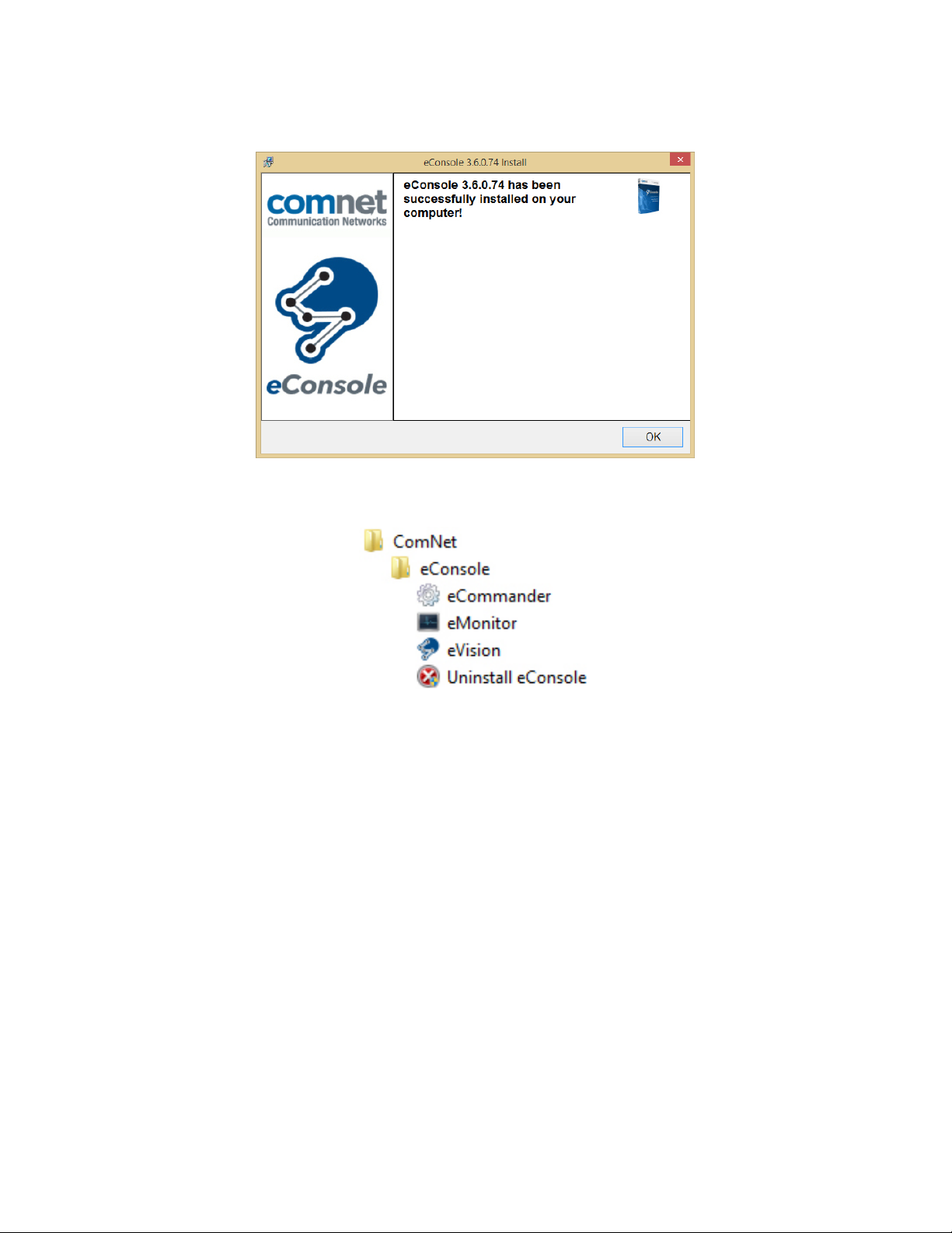
Step 6 – Once the software installations have been completed a confirmation window will be
displayed. Click Ok to complete the install procedure.
After the installation is completed, shortcuts will be placed in the Start Menu in the following
location: Start › All Programs › ComNet › eConsole
TECH SUPPORT: 1.888.678.9427
INS_eConsole_REV– 12/20/12 PAGE 8
Page 9
INSTALLATION AND OPERATION MANUAL ECONSOLE
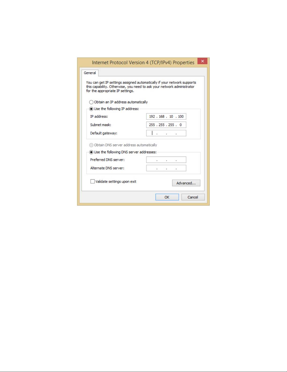
Configuring PC Network Interface Card
Please set the PC’s IP address and subnet mask to the same subnet as the switches that you wish
to connect to.
If there are switches in different subnets the user will need to add in all subnets into the NIC using
the Advanced menu option.
TECH SUPPORT: 1.888.678.9427
INS_eConsole_REV– 12/20/12 PAGE 9
Page 10
INSTALLATION AND OPERATION MANUAL ECONSOLE
eCommander
eCommander can be used to discover and configure all ComNet second generation switches on
the network. It also includes some useful wizards for fast switch configuration.
Note: Not all switches are compatible with eCommander. For a complete list of compatible
ComNet switch models please refer to the latest eConsole data sheet at www.comnet.net.
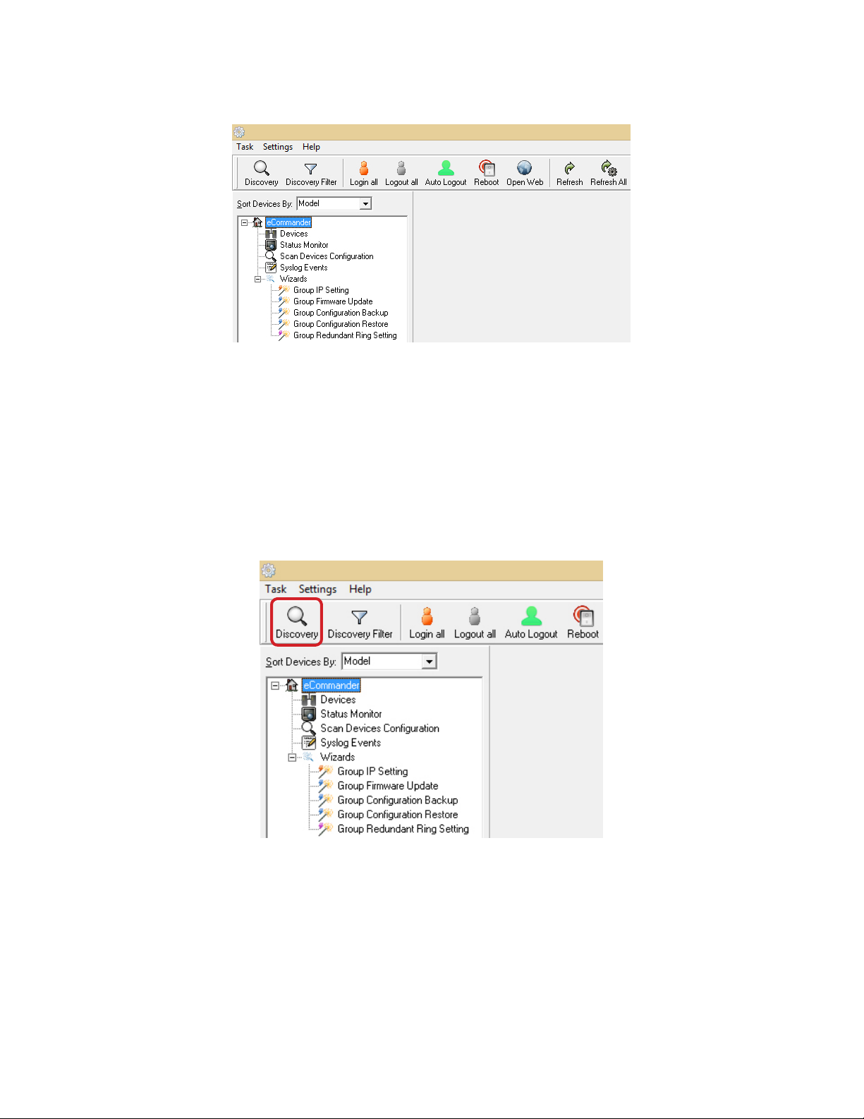
Discovery
The user can discover all the switches within the NIC subnet by simply clicking on the Discovery
button.
TECH SUPPORT: 1.888.678.9427
INS_eConsole_REV– 12/20/12 PAGE 10
Page 11
INSTALLATION AND OPERATION MANUAL ECONSOLE
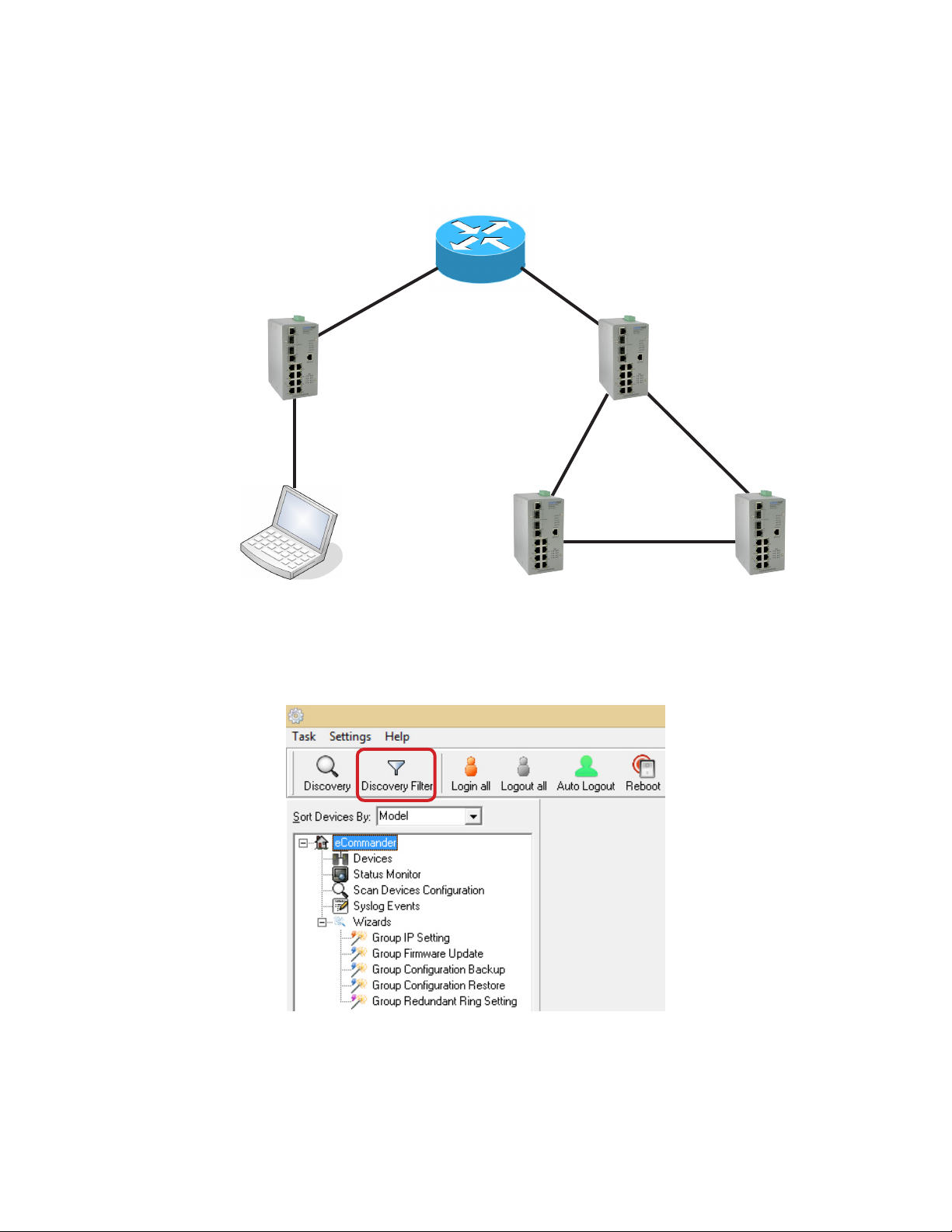
Discovery Filter
In order to manage and discover switches in a different domain, the user can use the
Discovery Filter to search and add the switches.
Router
192.168.2.254 / 24192.168.10.254 / 24
192.168 .10.1 / 24
192.168.10.66 / 24
PC with
eConsole
Note: The gateway of the PC must be the Router.
Step 1 – Click the Discovery Filter button.
192.168 .2.1 / 24
192.168.2.3 / 24192.168.2.2 / 24
TECH SUPPORT: 1.888.678.9427
INS_eConsole_REV– 12/20/12 PAGE 11
Page 12
INSTALLATION AND OPERATION MANUAL ECONSOLE
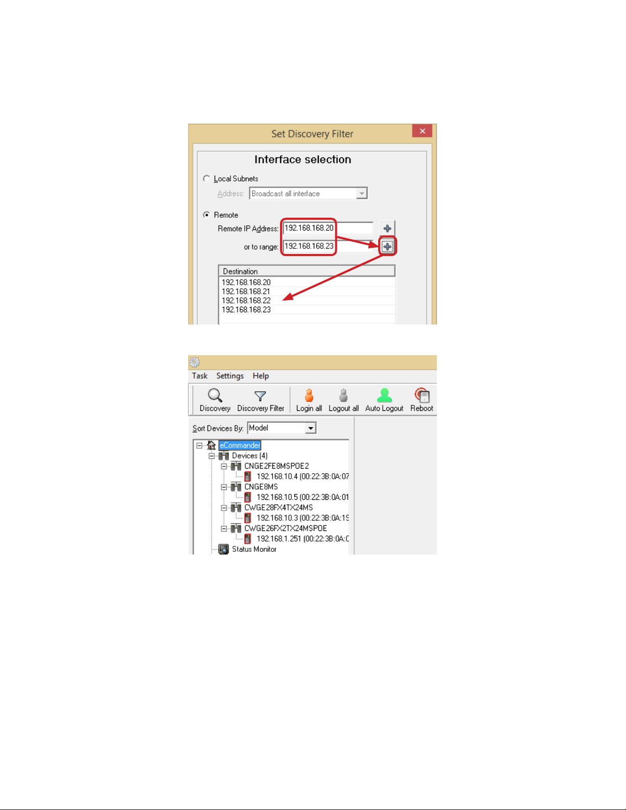
Step 2 – In the Remote section, enter the first remote IP and end remote IP range you need.
Click the + button to add in the IP range. A different subnet can also be added if needed. Then
click the OK button.
The switches will be found and added into the device list of eCommander.
TECH SUPPORT: 1.888.678.9427
INS_eConsole_REV– 12/20/12 PAGE 12
Page 13
INSTALLATION AND OPERATION MANUAL ECONSOLE
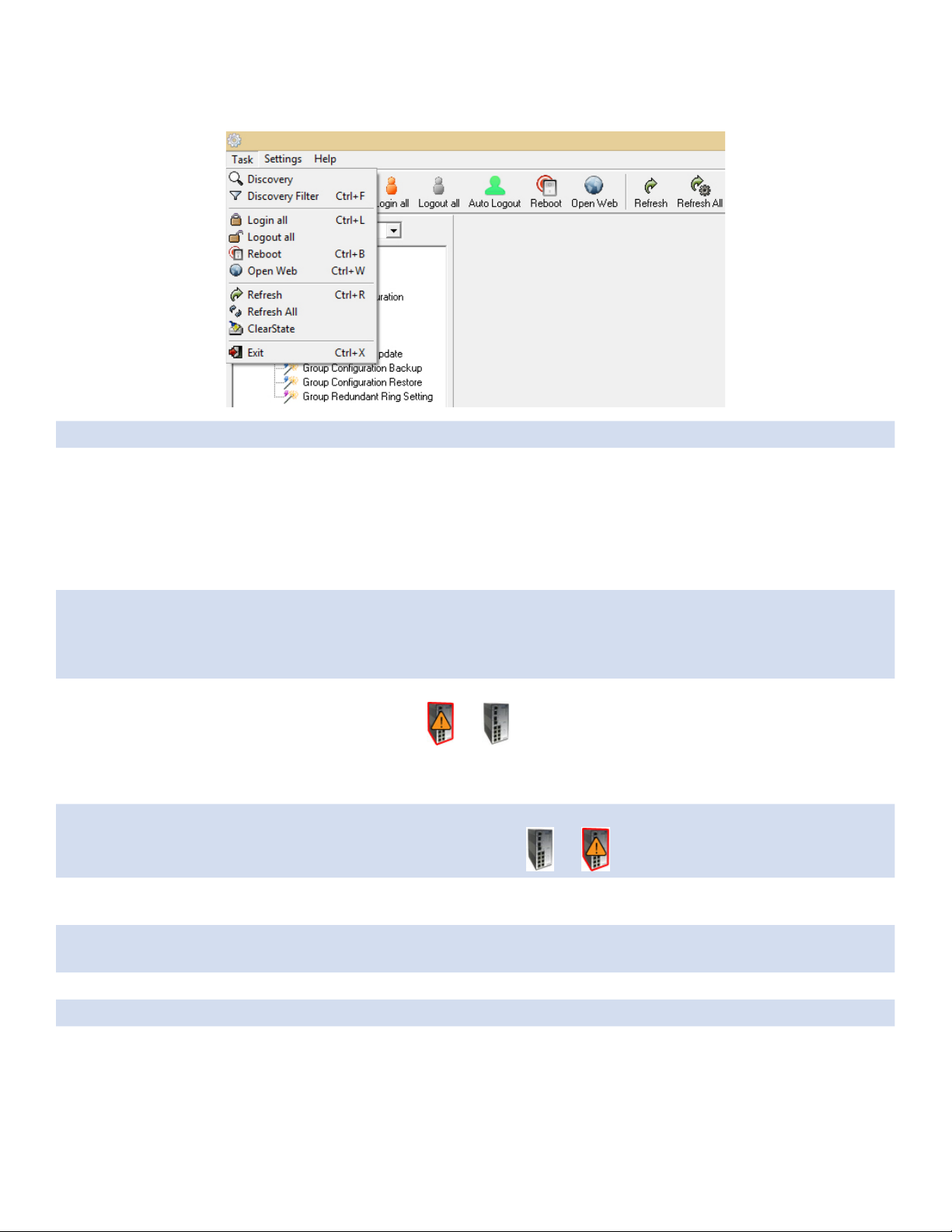
Task Menu
Label Description
Discovery Click Discovery to discover the switches on the same subnet as the PC. eCommander
will display all discovered switches on the management interface. eCommander
discovers switches depending on the discovery filter.
Note: All switches can have the same IP address such as when they are delivered
from the factory. eCommander can discover and change the IP addresses
by the Group IP Setting function.
Discovery Filter Local: eCommander will only discover all switches that are in the same specific IP
subnet of NIC that the user selects.
Remote: users are able to use specific IP address ranges to discover switches on
different subnets.
Login all eCommander can login to multiple switches that the user has selected. After login, the
switch icon will change from to
Note: By default, eCommander will logout of all switches automatically after
being idle for 300 seconds.
Logout all eCommander can logout from multiple switches that the user has selected. After logout
success, the switch icon will change from to .
Reboot eCommander can reboot multiple switches that the user has selected. When the user
clicks reboot, a dialog window will be displayed on screen to confirm.
Open Web eCommander will open the default browser of your OS automatically and navigate to
the selected switches web GUI.
Refresh Refresh the specific switches management interface and switch configuration interface.
Refresh All Refresh all switches management interfaces and switch configuration interfaces.
Clear state User can clear the device icon status.
TECH SUPPORT: 1.888.678.9427
INS_eConsole_REV– 12/20/12 PAGE 13
Page 14
INSTALLATION AND OPERATION MANUAL ECONSOLE
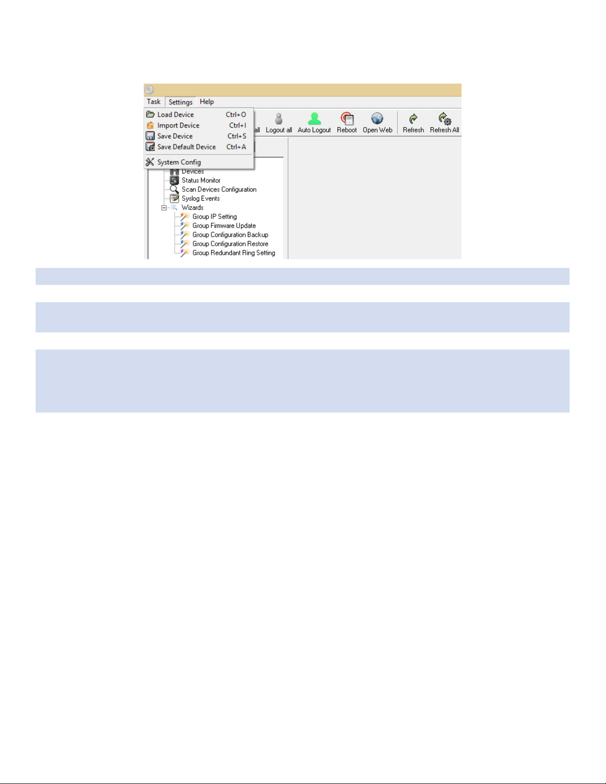
Settings Menu
Label Description
Load Device Users are able to re-load the IP address list (The old list will be cleared).
Import Device Users are able to re-load the IP address list (The old list will remain and any new devices
will be added).
Save Device Users are able to save the IP address list on the Discovery Filter/Remote page.
Save Default
Device
Users can save the device list as a default.
On future starts eCommander will display the devices directly, without re-discovery.
Note: to use this function you must have enabled System Config menu › Load
default device when start commander.
System Config Auto Logout time : Change the timer of the Auto logout.
Syslog server : Enable or disable eCommander’s built-in syslog server.
Load default device when start commander : When eCommander starts it will
automatically read the last used device information
Note: to use this function you must also use the Settings menu › Save Default
Device option.
Start minimize to system tray: Minimize the eCommander to the windows taskbar when
the eCommander is first started.
Run at Windows startup: Enable to run eCommander automatically at Windows startup
Discover new devices without clearing device list: Enable to discover new devices
without clearing previous devices in the device list.
State Banner: Enable to display the switch’s port state.
TECH SUPPORT: 1.888.678.9427
INS_eConsole_REV– 12/20/12 PAGE 14
Page 15

INSTALLATION AND OPERATION MANUAL ECONSOLE
Help
Label Description
About Display eCommander version and build information.
Icons Introduction
The most commonly used functions are provided in the main icon bar so the user can use these
function directly without the need to find them in menus.
Icon Description
Please refer to Task Menu section
Please refer to Task Menu section
Please refer to Task Menu section
Please refer to Task Menu section
eCommander will logout of the device automatically
Please refer to Task Menu section
Please refer to Task Menu section
Please refer to Task Menu section
Please refer to Task Menu section
eCommander Group IP Wizard can configure the IP Address of
multiple switches. The function will be introduced in more detail in the
eCommader Wizards section.
eCommander Group Firmware Wizard can update the firmware of
multiple switches. The function will be introduced in more detail in the
eCommader Wizards section.
TECH SUPPORT: 1.888.678.9427
eCommander Group Redundant Ring Wizard can set the C-Ring function
of multiple switches. The function will be introduced in more detail in
the eCommader Wizards section.
Please refer to the Help Menu section.
INS_eConsole_REV– 12/20/12 PAGE 15
Page 16

INSTALLATION AND OPERATION MANUAL ECONSOLE
Devices list
All compatible switches discovered will be added into the device list and also the total devices
searched. The user can start managing the switch by clicking on the switch and logging in.
LED and Port Status
Users are able to get the switches LED and port status information by this simple interface.
Icon Description
Show the IP and MAC address of the switch.
Show the port link status of the switch.
TECH SUPPORT: 1.888.678.9427
Show the switch LED status.
INS_eConsole_REV– 12/20/12 PAGE 16
Page 17

INSTALLATION AND OPERATION MANUAL ECONSOLE
Status Monitor
The Status Monitor provides an interface for the user to monitor the switches in the network. Any
disconnected switches will be marked and also the alarm will sound.
Label Description
Query Period Timer to query for switch status.
Query Timeout
Beep Alarm Enable/disable the beep alarm after a device fails
Sound filename
defined by user
Redetect the
replaced error
devices
Delete Selected
Devices
Refresh Refresh the device status.
Device will be considered as in error after query timeout
Enables the user to customize the alarm sound.
Redetect the error device without waiting for the query period timer
Remove the selected device from the list
TECH SUPPORT: 1.888.678.9427
INS_eConsole_REV– 12/20/12 PAGE 17
Page 18

INSTALLATION AND OPERATION MANUAL ECONSOLE
Scan Devices Configuration
The Scan Devices Configuration can scan and compare the configuration on the devices
compared to the backup configuration on the PC to check whether the configuration on the
device is different.
Note: The naming format of the backup configuration must be (Model)_(Kernel Ver)_(Firmware
Ver)_(IP).xml or .bin (depending on switch backup file type supported). For example:
CWGE28FX4TX24MS_v7.12_v1.01_192.168.10.3.xml. Or the user can use the Group Configuration
Backup to save the backup file with the correct default file name.
Label Description
Source Directory Select the directory of backup configuration(s)
Auto Scan Enable Auto Scan
Every hour Scan every hour
Every day Scan everyday on certain time
Scan Now Scan configuration immediately
TECH SUPPORT: 1.888.678.9427
INS_eConsole_REV– 12/20/12 PAGE 18
Page 19

INSTALLATION AND OPERATION MANUAL ECONSOLE
Syslog Events
The built in Syslog server allows the user to check and save the events of the switches
automatically.
Label Description
Save Save system log info to an Excel file.
Clear
Auto Save Enable auto save of the event log when the below threshold is reached.
Threshold num Save the events when the number of messages reach this value.
Open saved file Open a saved log.
Clear existing system log.
Wizards
The wizards allow the user to do some basic settings on multiple devices at one time e.g. Set IP
Addresses, C-ring setting... etc.
Group IP Setting Wizard
The Group IP Setting Wizard allows the user to set the IP address of all devices in the list in just a
few steps.
STEP 1 – Select one or more devices to be configured.
TECH SUPPORT: 1.888.678.9427
INS_eConsole_REV– 12/20/12 PAGE 19
Page 20

INSTALLATION AND OPERATION MANUAL ECONSOLE
STEP 2 – Configure the IP address range or DHCP server IP address.
You can change the order of the switches to define which one is given which IP address
by using the arrow buttons on the right hand side.
STEP 3 – Apply to finish the configuration.
Group Firmware Update Wizard
This Group Firmware update allow the user to update a group of switches (with the same model
number only) at one time. This allows the user to save time doing the update manually one by one.
STEP 1 – Select one or more devices (must be the same model) to be configured.
TECH SUPPORT: 1.888.678.9427
INS_eConsole_REV– 12/20/12 PAGE 20
Page 21

INSTALLATION AND OPERATION MANUAL ECONSOLE
STEP 2 – Browse to select the new Firmware file to be upgraded.
STEP 3 – Click Upgrade to start the firmware upgrade process.
Warning: Please ensure that you do not remove power to the switch while the upgrade process is
in progress.
STEP: 4. After the upgrade process has completed, click Reboot to reboot all upgraded devices.
TECH SUPPORT: 1.888.678.9427
INS_eConsole_REV– 12/20/12 PAGE 21
Page 22

INSTALLATION AND OPERATION MANUAL ECONSOLE
Group Configuration Backup
This Group Configuration Backup allows the user to backup the configuration of multiple devices
(with the same model number only) automatically.
STEP 1 – Select one or multiple devices to be backed up.
STEP 2 – Browse to the directory to save the backup configuration and click Backup to start the
backup.
TECH SUPPORT: 1.888.678.9427
INS_eConsole_REV– 12/20/12 PAGE 22
Page 23

INSTALLATION AND OPERATION MANUAL ECONSOLE
Group Configuration Restore
The Group Configuration Restore allows the user to restore the configuration of multiple devices
(with the same model number only).
STEP 1 – Select one or multiple devices to be restored.
STEP 2 – Browse to the backup configuration file to be restored or check the Auto Filename Prefix
box to let the wizard detect the configuration file in the directory if it has been saved with the
default naming structure.
TECH SUPPORT: 1.888.678.9427
INS_eConsole_REV– 12/20/12 PAGE 23
Page 24

INSTALLATION AND OPERATION MANUAL ECONSOLE
Group Redundant Ring Setting
The Group Redundant Ring Setting allows user to configure ComNet C-Ring in multiple switches
(with the same model number only and that are using the same port numbers as part of the ring)
at one time.
Note: Different model number switches or for switches where the C-Ring port numbers are not
the same must be configured in separate wizard sessions.
STEP 1 – Select one or multiple devices to be configured with C-Ring.
STEP 2 – Select the ports you are using as ring ports in the list and click on Apply.
TECH SUPPORT: 1.888.678.9427
INS_eConsole_REV– 12/20/12 PAGE 24
Page 25

INSTALLATION AND OPERATION MANUAL ECONSOLE
eVision
Important Note
eVision monitors devices that support SNMP and LLDP. Both of these functions must be enabled
on each device. On some ComNet devices these features may not be enabled by default. If the
device you are looking for is not displayed or does not show any port links please check that the
above features are enabled on the device.
The SNMP Read Community setting must be the same on all devices and must match the eVision
SNMP Read setting in the System Config menu.
About eVision
eVision is a useful and powerful network topology utility. It is able to display the network topology
automatically. The network administrators are able to monitor the network devices and links
status via eVision immediately.
Topology Wizard
By default, the Topology wizard will pop up when eVision is started. Using the wizard the user
can discover devices and group settings etc. The wizard startup can also be enable/disabld by
selecting Edit › System Config › Initial Conf › Launch Wizard when system start from the Edit
menu.
There are two options in the wizard, which are:
Label Description
Detect Device Start the steps to discover devices and group settings
Load an Existing Topology File Load a backup Topology configuration file.
Please see the following steps for the Topology Wizard – Detect Device option.
TECH SUPPORT: 1.888.678.9427
INS_eConsole_REV– 12/20/12 PAGE 25
Page 26

INSTALLATION AND OPERATION MANUAL ECONSOLE
Step 1 – User can enter an IP range which allow it to scan for devices automatically, or user can
also add a device manually by using its known IP address by clicking Add.
Step 2 – Select Manage Group of Device for the Group setting or skip by selecting Set it up later
(if you select Set it up later, please go to Step 4).
TECH SUPPORT: 1.888.678.9427
INS_eConsole_REV– 12/20/12 PAGE 26
Page 27

INSTALLATION AND OPERATION MANUAL ECONSOLE
Step 3 – In the group management, user can add a new group and move devices into the different
groups required.
Step 4 – User can setup the GPS position of the devices by simply entering an address (internet
connection required). Double click on the Address field to enter the address. Once the
address has been entered click the Location button and the system will search online
for the Latitude and Longitude co-ordinates of that location and fill these in the table as
shown. If the address cannot be found you can also enter the co-ordinates manually by
double clicking on the relevant field. Click Finish to close the wizard.
TECH SUPPORT: 1.888.678.9427
INS_eConsole_REV– 12/20/12 PAGE 27
Page 28

INSTALLATION AND OPERATION MANUAL ECONSOLE
Device Discovery
User can add devices by using the built-in Discovery function.
Click the Discovery button located on the General tab in the main eVision interface. Enter the start
and end of the IP range you wish to discover and click Start to discover all devices in the selected
range.
Label Description
Clear list Clear previous discovery device list
TECH SUPPORT: 1.888.678.9427
INS_eConsole_REV– 12/20/12 PAGE 28
Page 29

INSTALLATION AND OPERATION MANUAL ECONSOLE
System Menu Bar
File
Label Hotkey Description
Ctrl + N Open a new topology graph
Ctrl + O Load a saved topology graph
Ctrl + I Import a saved topology into the current topology graph
Ctrl + C Close current topology graph
Ctrl + S Save current topology graph
Ctrl + L Save all open topology graphs
N/A Save current topology as default graph.
TECH SUPPORT: 1.888.678.9427
Ctrl + P Print current Topology graph
Ctrl + E Quit eVision
INS_eConsole_REV– 12/20/12 PAGE 29
Page 30

INSTALLATION AND OPERATION MANUAL ECONSOLE
Edit
Label Hotkey Description
Ctrl + D Open the device Discovery tool
N/A Auto Polling: Enable or disable Auto Polling function of devices.
Polling Time(s): Polling interval timer.
Device(s) / Interval: How many devices to poll at one time. Set to
zero for all devices.
Trap Agent Alive: Enable trap agent so eVision can receive SNMP
traps.
Trap Port: Specifies the port used by the Trap Agent
Topology agent: Enable / Disable topology agent function
SNMP Community: SNMP community read and write settings.
Version: SNMP version V1 or V2
Time out: SNMP timeout interval.
Explorer Path: Specify the Internet browser path.
Entry: Auto save the log file when it reaches this number of
entries.
Daily: Auto save the log file at a certain time each day
Load Topology: Load the default topology when eVision is
opened
Startup: Launch eVision on Windows startup.
Minimize: Minimize eVision after startup
Discovery new device without cleaning: Discover new devices
without clearing any current discovered devices.
Launch wizard when system starts: Launch the Topology wizard
every time eVision starts.
TECH SUPPORT: 1.888.678.9427
INS_eConsole_REV– 12/20/12 PAGE 30
Page 31

INSTALLATION AND OPERATION MANUAL ECONSOLE
N/A Path Size: Set the width of the path lines drawn between devices.
Font Size: Set the size of the font used to display the device
name/label.
Show Icon: Enable / Disable the device icon from being
displayed.
Background: Set the topology graph background color.
Font Color: Set the font color used for the device name/label.
Show Port Number on Link: Enable / Disable the port number
being shown for each device link.
Link Option: Set the link colors for the 4 different link states.
Background Option: User can load any picture as the topology
view background. An example is shown below.
In the Device database management the user can modify or
N/A
add a new device OID, link up, link down, trap and locate icons.
Please refer to the next section.
N/A Edit current topology graph name.
TECH SUPPORT: 1.888.678.9427
INS_eConsole_REV– 12/20/12 PAGE 31
Page 32

INSTALLATION AND OPERATION MANUAL ECONSOLE
Device Database Management
User can add devices to the database using this screen. Icons and OID data can also be updated
for existing devices in the database.
To add a new device to the database enter the OID (obtained from the device manufacturer) and
icon names for each of the 4 available icons and then click Add.
To modify an existing entry in the database select the entry and then update the details followed
by clicking Modify.
To delete an entry from the database select the entry and then click the Delete button.
Once all the required changes have been made click Save to save the new database.
Note: Icons will need to be saved in the icon folder located at …\ComNet\eConsole\rec\device
Note: User can add non-ComNet devices into the database provided the device supports SNMP
and LLDP protocols. These protocols must be enabled on the target devices in order for
eVision to recognize them.
The SNMP Read Community setting must be the same on all devices and must match the
eVision SNMP Read setting in the System Config menu.
ComNet cannot provide any support for 3rd party devices.
TECH SUPPORT: 1.888.678.9427
INS_eConsole_REV– 12/20/12 PAGE 32
Page 33

INSTALLATION AND OPERATION MANUAL ECONSOLE
View
Icon Hotkey Description
Ctrl + Up Zoom in on the topology.
Ctrl + Down Zoom out of the topology.
N/A Clear topology state of the current graph
N/A Recheck Device: Checks if the devices still exist or not. Devices will
be removed if they no longer exist.
Recheck link: Check the links between devices, the links will be
removed if the connection has broken.
Recheck state: Check current state of devices, any devices where
the status has altered will be updated.
Recheck type: Check device model, will update the icon when
replacing a device with the same IP but a different model.
N/A Transform: Click to move the entire topology around.
Pick: Click to be able to select and drag a particular device to a new
location.
Line: Click to edit a line manually.
Layout
In the eVision Topology View, there are 3 types of layout which can arrange the device topology in
different automatic ways, this allows the user to save time to drag every device manually.
TECH SUPPORT: 1.888.678.9427
INS_eConsole_REV– 12/20/12 PAGE 33
Page 34

INSTALLATION AND OPERATION MANUAL ECONSOLE
Management
Select Management to show the Management menu.
Label Hotkey Description
Group N/A New: Add a new group.
Delete: Delete selected group
Rename: Rename selected group
Move to Group: Move the selected device to a new group
Help
Map
Management
About N/A Show the version information of eVision
N/A Edit the device’s map related information, e.g. Latitude and
Longitude. User can also enable or disable devices to be
displayed on the map.
Label
Hotkey Description
TECH SUPPORT: 1.888.678.9427
INS_eConsole_REV– 12/20/12 PAGE 34
Page 35

INSTALLATION AND OPERATION MANUAL ECONSOLE
Tool Bar
General
Icon Description
Please refer to the eVision Edit
Menu section
Please refer to the eVision View
Menu section
Please refer to the eVision View
Menu section
Please refer to the eVision
Management Menu section
Open the Topology wizard
TECH SUPPORT: 1.888.678.9427
INS_eConsole_REV– 12/20/12 PAGE 35
Page 36

INSTALLATION AND OPERATION MANUAL ECONSOLE
Topology Management
Icon Description
Please refer to the eVision View Menu section
Please refer to the eVision View Menu section
Please refer to the eVision View Menu section
Please refer to the eVision View Menu section
Please refer to the eVision View Menu section
Layout devices automatically (KK Layout)
Centralize the screen on the devices
Locate a specific device by its IP address
Display device label information as IP address, System Name, Annotation,
disable the label information.
TECH SUPPORT: 1.888.678.9427
INS_eConsole_REV– 12/20/12 PAGE 36
Page 37

INSTALLATION AND OPERATION MANUAL ECONSOLE
Map Management
Task Description
Refresh the map display
Back to Global Group
Go to upper level group
Map zoom in
Map zoom out
Print map display
Save map
TECH SUPPORT: 1.888.678.9427
INS_eConsole_REV– 12/20/12 PAGE 37
Page 38

INSTALLATION AND OPERATION MANUAL ECONSOLE
Device Tree & Group Tree
Detected devices will be displayed in the Device Tree and Group Tree.
In the Device Tree the user can double click on a device to search and navigate to that device in
the topology graph, the user can also right click on a device for the device setting options.
In Group Tree, by default all devices will be placed under the Global Group. A Device that is
enabled on the Map display will have a tick on it.
The user can also right click on the group for the group management options or right click on a
device for device setting options.
TECH SUPPORT: 1.888.678.9427
INS_eConsole_REV– 12/20/12 PAGE 38
Page 39

INSTALLATION AND OPERATION MANUAL ECONSOLE
Topology
The discovered device’s network topology will be shown in the Topology Graph area automatically.
Important Note
eVision monitors devices that support SNMP and LLDP. Both of these functions must be enabled
on each device. On some ComNet devices these features may not be enabled by default. If the
device you are looking for is not displayed or does not show any port links please check that the
above features are enabled on the device.
The SNMP Read Community setting must be the same on all devices and must match the eVision
SNMP Read setting in the System Config menu.
TECH SUPPORT: 1.888.678.9427
INS_eConsole_REV– 12/20/12 PAGE 39
Page 40

INSTALLATION AND OPERATION MANUAL ECONSOLE
In the topology graph, the user can right click on a device for the device settings options or right
click on a line for the Link Status or Link Annotation.
Icon Description
Device normal
Device link down or no longer detected
›
Device back online after failure or link down
Locating device (flashing).
Note: Supported devices only.
Link selected
Link down/failure
Backup link
Link back online after previous failure
TECH SUPPORT: 1.888.678.9427
INS_eConsole_REV– 12/20/12 PAGE 40
Page 41

INSTALLATION AND OPERATION MANUAL ECONSOLE
Map
The devices with Map Active enabled will be shown on the map. With the help of this map the
user can see where the devices are installed.
Two types of map display are possible roadmap or satellite.
The user can also display a label for each device by enabling the Label option.
Note: Retrieving the Map display requires an Internet connection.
TECH SUPPORT: 1.888.678.9427
INS_eConsole_REV– 12/20/12 PAGE 41
Page 42

INSTALLATION AND OPERATION MANUAL ECONSOLE
System Log Area
eVision also has a built-in SNMP trap manager system log that can record all SNMP trap events
such as link down event etc.
To enable this feature each device must be enabled with SNMP and have the eVision PC set as a
trap station in the devices SNMP configuration.
Task Description
Clear log
Save log to file.
Refresh log.
TECH SUPPORT: 1.888.678.9427
INS_eConsole_REV– 12/20/12 PAGE 42
Page 43

INSTALLATION AND OPERATION MANUAL ECONSOLE
eMonitor
By using the eMonitor application the user can monitor the alive status of all IP devices. The
application supports any IP addressable device on the network.
Add device
When eMonitor is launched the Add device screen will be presented where the user can search
for and add in devices by entering the IP address search range and then clicking the checkmark
button followed by Apply.
Label Description
Group Add a new Group
Host Enter the IP address prefix and a range to be added.
TECH SUPPORT: 1.888.678.9427
INS_eConsole_REV– 12/20/12 PAGE 43
Page 44

INSTALLATION AND OPERATION MANUAL ECONSOLE
System Bar
File
Label Hotkey Description
Ctrl + N Stat new eMonitor session.
Ctrl + O Open previous saved eMonitor session
Ctrl + S Save current eMonitor session.
Ctrl + E Quit eMonitor
Tool
Label Description
System Config Report: Enable / Disable the report.
Agent: Enable / Disable the checking agent and set the value of the time interval and
timeout.
TECH SUPPORT: 1.888.678.9427
INS_eConsole_REV– 12/20/12 PAGE 44
Page 45

INSTALLATION AND OPERATION MANUAL ECONSOLE
About
eMonitor version
Function Bar
Label Description
Start a new monitor session
Open a saved file
Save the current file
Add a device or range of devices
Remove the selected device / group
Start or Stop the monitor
Interval Checking interval timer
TECH SUPPORT: 1.888.678.9427
Timeout Time out timer
Find Find specific device by using IP address
INS_eConsole_REV– 12/20/12 PAGE 45
Page 46

INSTALLATION AND OPERATION MANUAL ECONSOLE
Group Tree
Devices will be show in the Group Tree.
Label Description
Add Add a device or group of devices.
Delete Remove selected device / group.
Edit Edit selected device / group and description.
TECH SUPPORT: 1.888.678.9427
INS_eConsole_REV– 12/20/12 PAGE 46
Page 47

INSTALLATION AND OPERATION MANUAL ECONSOLE
Monitor Area
Current status of each device is shown in the Monitor table. The status for active devices will be
show with a green icon and timeout devices will be shown with a red icon.
TECH SUPPORT: 1.888.678.9427
INS_eConsole_REV– 12/20/12 PAGE 47
Page 48

INSTALLATION AND OPERATION MANUAL ECONSOLE
TroubleShooting
eConsole will not run on your computer?
Please make sure your computer has installed Java Runtime Environment (JRE).
If not, please install Java Runtime Environment (JRE) 6 Update 3 (as minimum version) from the
Java website, at http://java.com/download
License key warning message
Symptom: When user launches eConsole, the computer displays a warning message as below.
Situation: You have installed a licensed version of eConsole and the computer cannot detect the
USB license key. Please insert the USB license key to enter licensed mode and then press
OK or press Cancel to limit the operation to 10 devices.
SYSLOG warning message
Symptom: When user launches eConsole, the computer displays a warning message as below.
Situation: Another software application is currently in operation as the Syslog Server. Check if
there are any third party System Log Servers (e.g., tftpd) running on the computer. If you
do not care about the system log function, press Ignore to continue.
TECH SUPPORT: 1.888.678.9427
INS_eConsole_REV– 12/20/12 PAGE 48
Page 49

INSTALLATION AND OPERATION MANUAL ECONSOLE
Why can’t eVision receive SNMP traps?
Symptom: When user launches eVision, the computer displays a warning message as below.
Situation: Another software application is currently in operation as the SNMP Trap manager. Check
if there are any third party SNMP Software (e.g., MG-Soft or SNMPc) applications running
on the computer. Please stop these applications, because they occupy the SNMP port
required by eVision.
TECH SUPPORT: 1.888.678.9427
INS_eConsole_REV– 12/20/12 PAGE 49
Page 50

MECHANICAL INSTALLATION INSTRUCTIONS
ComNet Customer Service
Customer Care is ComNet Technology’s global service center, where our
professional staff is ready to answer your questions at any time.
Email ComNet Global Service Center: customercare@comnet.net
3 CORPORATE DRIVE | DANBURY, CT 06810 | USA
T: 203.796.5300 | F: 203.796.5303 | TECH SUPPORT: 1.888.678.9427 | INFO@COMNET.NET
8 TURNBERRY PARK ROAD | GILDERSOME | MORLEY | LEEDS, UK LS27 7LE
T: +44 (0)113 307 6400 | F: +44 (0)113 253 7462 | INFO-EUROPE@COMNET.NET
© 2014 Communications Networks Corpor ation. All Right s Reserved. “ComNet” and t he “ComNet Logo” are registered trademarks of Communication Networks, LLC.
 Loading...