

Comnet CLRVE1COAX/M, CLRVE2COAX, CLTVE1COAXPOE/M, CLRVE1COAX Installation And Operation Manual
Page 1

INSTALLATION AND OPERATION MANUAL
CL(T,R)VE(1,2)COAX[POE][/M]
ANALOG AND IP VIDEO OVER COAX
This manual serves the following
ComNet Model Numbers:
CLT VE1C OA X /M
CLRVE1COAX/M
CLTVE1COAXPOE/M
CLRVE1COAX
CLRVE2COAX
The ComNet™ CL(T,R)VE(1,2)COAX[POE][/M] is a communications link that combines
composite analog baseband video and 10/100T(X) Ethernet on a single RG59 coaxial
cable and transmits it up to 500 meters. The device is particularly suited to applications
where the addition of IP Video to an existing analog video system is required. The
CLTVE1COAXPOE/M model can provide power to the IP device via PoE.
LED indicators are provided for rapidly ascertaining the operating status of the
device. See Figure 6 on Page 5 for an explanation of the LED Indicators.
Packaged in a rugged, compact sized housing, these units are designed for surface or
stand-alone mounting, or may be DIN-rail mounted by the addition of ComNet model
DINBKT2 Adaptor plate kit. Refer to Installation Considerations on Page 5 and
Figure A on Page 6 for mounting instructions.
See Figures 1 – 6 for complete installation instructions.
INS_CL(T,R)VE(1,2)COAX[POE][M]_REV- 04/25/13 PAGE 1
Page 2
INSTALLATION AND OPERATION MANUAL CL(T,R)VE(1,2)COAX[POE][/M]
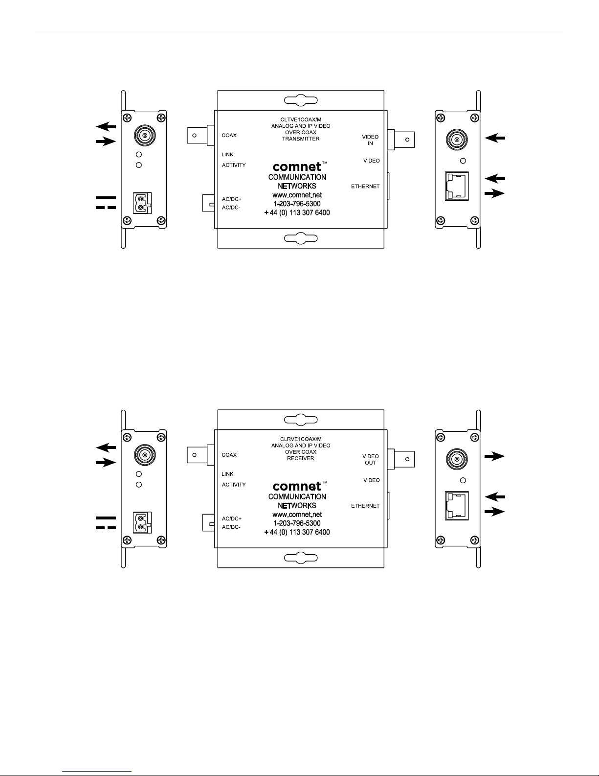
FIGURE 1 – CLTVE1COAX/M TRANSMITTER
COAX
LINK TO RX
MODULE
Black w/ White
Stripe (AC or DC+)
Black (AC or DC–)
Operating Power: 12 to 36 VDC or 24 VAC
Power Consumption: 2W
FIGURE 2 – CLRVE1COAX/M RECEIVER
ANALOG
VIDEO IN
ETHERNET
COAX
LINK TO TX
MODULE
Black w/ White
Stripe (AC or DC+)
Black (AC or DC–)
Operating Power: 12 to 36 VDC or 24 VAC
Power Consumption: 2W
ANALOG
VIDEO OUT
ETHERNET
INS_CL(T,R)VE(1,2)COAX[POE][M]_REV- 04/25/13 PAGE 2TECH SUPPORT: 1.888.678.9427
Page 3

INSTALLATION AND OPERATION MANUAL CL(T,R)VE(1,2)COAX[POE][/M]
FIGURE 3 – CLTVE1COAXPOE/M TRANSMITTER WITH POE
COAX
LINK
TO RX
MODULE
Black w/ White
Stripe (AC or DC+)
Black (AC or DC–)
Operating Power: 12 to 36 VDC or 24 VAC
Power Consumption: 2W
Note: Power consumption does not include that of Powered Device(s) (PD)
ANALOG
VIDEO IN
ETHERNET
IEEE 802.3at
PoE (30W Max)
FIGURE 4 – CLRVE1COAX RECEIVER
ETHERNET
Operating Power: 9 to 18 VDC
Power Consumption: 2W
ANALOG
VIDEO OUT
COAX LINK TO
TX MODULE
Black (GND)
Black w/ White
Stripe (+Vin)
INS_CL(T,R)VE(1,2)COAX[POE][M]_REV- 04/25/13 PAGE 3TECH SUPPORT: 1.888.678.9427
Page 4

INSTALLATION AND OPERATION MANUAL CL(T,R)VE(1,2)COAX[POE][/M]
FIGURE 5 – CLRVE2COAX RECEIVER
CH 1
ETHERNET
CH1 ANALOG
VIDEO OUT
CH1 COAX LINK
CH 2
ETHERNET
TO TX MODULE
CH2 ANALOG
VIDEO OUT
CH2 COAX LINK
TO TX MODULE
Black (GND)
Black w/ White
Stripe (+Vin)
Operating Power: 9 to 18 VDC
Power Consumption: 4W
INS_CL(T,R)VE(1,2)COAX[POE][M]_REV- 04/25/13 PAGE 4TECH SUPPORT: 1.888.678.9427
Page 5

INSTALLATION AND OPERATION MANUAL CL(T,R)VE(1,2)COAX[POE][/M]
FIGURE 6 – INDICATING LEDS
ETHERNET LINK
(Yellow/Off)
ETHERNET ACTIVITY
(Solid/Flashing Green)
GREEN YELLOW RED OFF
COAX LINK
Coax interface linked N/A Coax Interface Not Linked Unit Powered Down
COAX ACTIVITY
Activity detected (flashing or
N/A N/A No Activity
solid)
POE
(CLTVE1COAXPOEM/M)
VIDEO DETECT
ETHERNET LINK
ETHERNET ACTIVITY
Installation Considerations
This Ethernet unit is supplied as a Standalone/Rack module. Units should be installed in dry locations protected from extremes of
temperature and humidity.
C1-US, C1-EU, C1-AU or C1-CH Card Cage Racks
CAUTION: Although the units are hot-swappable and may be installed without turning power off to the rack, ComNet recommends
that the power supply be turned off and that the rack power supply is disconnected from any power source. Note: Remove
electrical connector before installing in card cage rack.
1. Make sure that the card is oriented right side up, and slide it into the card guides in the rack until the edge connector at the
back of the card seats in the corresponding slot in the rack’s connector panel. Seating may require thumb pressure on the top
and bottom of the card’s front panel.
PoE power is being supplied. N/A N/A PoE is not supplied.
Video signal detected on the
Video BNC
N/A No Video signal detected on
the Video BNC
Unit Is Powered Down.
N/A Interface Linked N/A Interface Not Linked
Activity Detected N/A N/A No Activity Detected
CAUTION: Take care not to press on any of the LEDs.
2. Tighten the two thumb screws on the card until the front panel of the card is seated against the front of the rack.
WARNING: Unit is to be used with a Listed Class 2 power supply.
IMPORTANT SAFEGUARDS:
A) Elevated Operating Ambient - If installed in a closed or multi-unit rack assembly, the operating ambient temperature of the rack
environment may be greater than room ambient. Therefore, consideration should be given to installing the equipment in an
environment compatible with the maximum ambient temperature (Tma) specified by the manufacturer.
B) Reduced Air Flow - Installation of the equipment in a rack should be such that the amount of air flow required for safe operation
of the equipment is not compromised.
INS_CL(T,R)VE(1,2)COAX[POE][M]_REV- 04/25/13 PAGE 5TECH SUPPORT: 1.888.678.9427
Page 6

INSTALLATION AND OPERATION MANUAL CL(T,R)VE(1,2)COAX[POE][/M]
FIGURE A
Dimensions are for a standard ComNet™ one slot module
.156 [3.96 mm]
.313 [7.95 mm]
FIGURE B
Dimensions are for a small size ComNet™ surface mount module
FIGURE C
Dimensions are for a two-high small size ComNet™ surface mount module
3 CORPORATE DRIVE | DANBURY, CT 06810 | USA
T: 203.796.5300 | F: 203.796.5303 | TECH SUPPORT: 1.888.678.9427 | INFO@COMNET.NET
8 TURNBERRY PARK ROAD | GILDERSOME | MORLEY | LEEDS, UK LS27 7LE
T: +44 (0)113 307 6400 | F: +44 (0)113 253 7462 | INFO-EUROPE@COMNET.NET
© 2016 Communications Networks Corporation. All Rights Reserved. “ComNet” and the “ComNet Logo” are registered trademarks of Communication Networks, LLC.
INS_CL(T,R)VE(1,2)COAX[POE][M]_REV- 04/25/13 PAGE 6TECH SUPPORT: 1.888.678.9427
 Loading...