

Page 1
INSTALLATION AND OPERATION MANUAL
CLFE(X)EO(C,U) Series
ETHERNET OVER COPPER EXTENDER
WITH PASS-THROUGH POE TO 15 WATTS
This manual serves the following
ComNet Model Numbers:
CLFE1EOC
CLFE4EOC
CLFE8EOC
CLF E16EOC
CLFE1EOU
CLFE4EOU
CLFE8EOU
CLF E16EOU
The ComNet™ CopperLine® Ethernet over copper line supports up to sixteen
channels of 10/100Mbps Ethernet with Pass-through PoE over twisted pair cable
(CAT-5, UTP), or over coaxial cable. The single channel units may be powered by a
PoE switch or the included power supply. Four, eight, and sixteen channel units
operate from local power. These units provide the ultimate flexibility for extending
a powered device (PD) over long distance copper. DIP switches are provided for userselection of local or remote, 10 or 100Mbps, and 1 pair or 4 pair (UTP) settings.
Bi-color (Red/Green) LED indicators are provided for rapidly ascertaining equipment
operating status. Table 2 on Page 9 describes the LED indicators for each light on
the unit.
The CLFE8EO(C,U) and CLFE16EO(C,U) are 1RU rack mountable units. The
CLFE4EO(C,U) units are interchangeable between stand-alone or card mount
configurations, or may be DIN-rail mounted by the addition of ComNet model
DINBKT1 or DINBKT4 adaptor plate. The CLFE1EO(C,U) units are stand-alone, or
may be DIN-rail mounted by the addition of ComNet model DINBKT4 adaptor. See
Figures A through C on Page 11 for mounting instructions.
INS_CLFE(X)EO(C,U)_REV– 10/27/11 PAGE 1TECH SUPPORT: 1.888.678.9427
Page 2
INSTALLATION AND OPERATION MANUAL CLFE(X)EO(C,U) SERIES
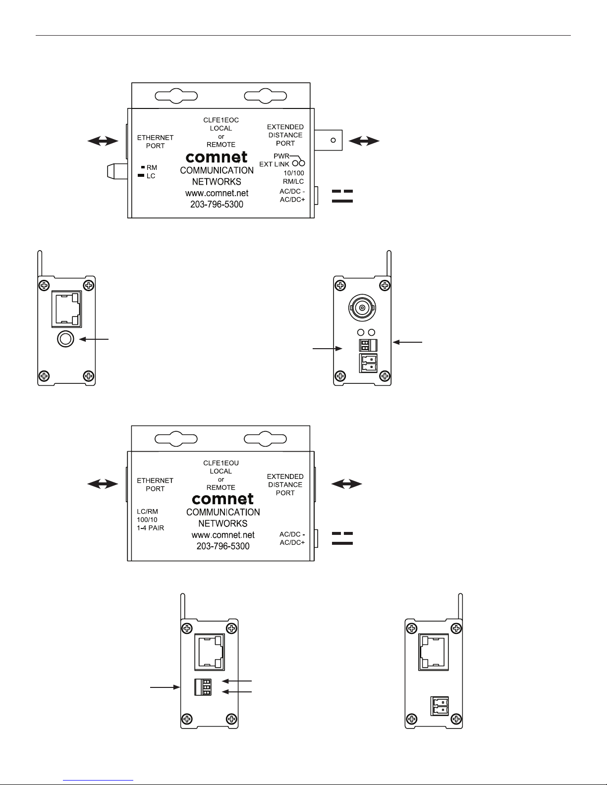
FIGURE 1 – CLFE1EOC SINGLE CHANNEL COAX UNIT
ETHERNET
FIGURE 2 – CLFE1EOC SINGLE CHANNEL COAX UNIT
Local/Remote push button
See Installation Instructions,
Step 3
Local/Remote
DIP switch
See Installation
Instructions, Step 3
FIGURE 3 – CLFE1EOU SINGLE CHANNEL UTP UNIT
EXT DISTANCE
Black w/ White
Stripe (AC or DC–)
Black (AC or DC+)
Power: Operates on PoE power
OR 9 to 36 VDC
OR 24 VAC
Power Consumption: 1.5 W
10/100 data rate DIP switch
See Installation Instructions,
Step 1
ETHERNET
FIGURE 4 – CLFE1EOU SINGLE CHANNEL UTP UNIT
Local/Remote DIP switch
10/100 data rate DIP switch
See Installation Instructions, Step 1
TECH SUPPORT: 1.888.678.9427
See Installation Instructions, Step 3
Wire pair DIP switch
See Installation Instructions, Step 2
EXT DISTANCE
Black w/ White
Stripe (AC or DC–)
Black (AC or DC+)
Power: Operates on PoE power
OR 9 to 36 VDC
OR 24 VAC
Power Consumption: 1.5 W
INS_CLFE(X)EO(C,U)_REV– 10/27/11 PAGE 2
Page 3
INSTALLATION AND OPERATION MANUAL CLFE(X)EO(C,U) SERIES
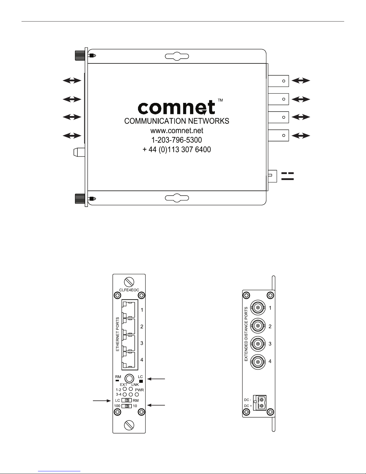
FIGURE 3 – CLFE4EOC FOUR CHANNEL SURFACE OR RACK MOUNT COAX UNIT
CH1 ETHERNET
CH2 ETHERNET
CH3 ETHERNET
CH4 ETHERNET
CH1 EXT
DISTANCE
CH2 EXT
DISTANCE
CH3 EXT
DISTANCE
CH4 EXT
DISTANCE
Black w/ White
Stripe (DC–)
Black (DC+)
Operating Power: 9 to 15 VDC
Power Consumption: 5W
FIGURE 4 – CLFE4EOC FOUR CHANNEL SURFACE OR RACK MOUNT COAX UNIT
Local/Remote push button
See Installation Instructions,
Step 3
Local/Remote DIP switch
See Installation Instructions,
Step 3
10/100 data rate
DIP switch
See Installation
Instructions, Step 1
TECH SUPPORT: 1.888.678.9427
INS_CLFE(X)EO(C,U)_REV– 10/27/11 PAGE 3
Page 4
INSTALLATION AND OPERATION MANUAL CLFE(X)EO(C,U) SERIES
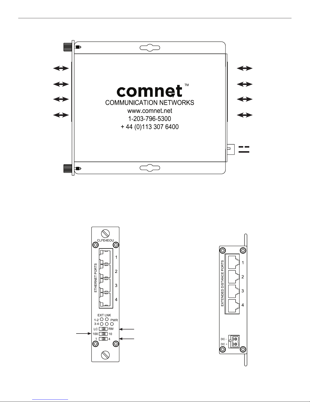
FIGURE 5 – CLFE4EOU FOUR CHANNEL SURFACE OR RACK MOUNT UTP UNITS
CH1 ETHERNET
CH2 ETHERNET
CH3 ETHERNET
CH4 ETHERNET
CH1 EXT
DISTANCE
CH2 EXT
DISTANCE
CH3 EXT
DISTANCE
CH4 EXT
DISTANCE
Black w/ White
Stripe (DC–)
Black (DC+)
Operating Power: 9 to 15 VDC
Power Consumption: 5W
FIGURE 6 – CLFE4EOU FOUR CHANNEL SURFACE OR RACK MOUNT UTP UNITS
Local/Remote DIP switch
Data rate DIP switch
See Installation Instructions, Step 1
See Installation Instructions, Step 3
Wire pair DIP switch
See Installation Instructions, Step 2
TECH SUPPORT: 1.888.678.9427
INS_CLFE(X)EO(C,U)_REV– 10/27/11 PAGE 4
Page 5

INSTALLATION AND OPERATION MANUAL CLFE(X)EO(C,U) SERIES
FIGURE 7 – CLFE8EOC MULTICHANNEL RACK COAX UNITS
CH1 ETHERNET
CH2 ETHERNET
CH3 ETHERNET
CH4 ETHERNET
CH5 ETHERNET
CH6 ETHERNET
CH7 ETHERNET
CH8 ETHERNET
Data rate DIP switch
See Installation
Instructions, Step 1
FIGURE 8 – CLFE8EOU MULTICHANNEL RACK UTP UNITS
CH8 EXT DISTANCE
CH7 EXT DISTANCE
Data rate DIP switch
See Installation
Instructions, Step 1
CH6 EXT DISTANCE
CH5 EXT DISTANCE
Operating Power: 9 to 15 VDC
Power Consumption: 10W
CH4 EXT DISTANCE
CH3 EXT DISTANCE
CH2 EXT DISTANCE
CH1 EXT DISTANCE
Black w/ White Stripe (DC–)
Black (DC+)
CH1 ETHERNET
CH2 ETHERNET
CH3 ETHERNET
CH4 ETHERNET
TECH SUPPORT: 1.888.678.9427
CH5 ETHERNET
CH6 ETHERNET
CH7 ETHERNET
CH8 ETHERNET
Wire pair DIP switch
See Installation
Instructions, Step 2
Data rate DIP switch
See Installation
Instructions, Step 1
CH8 EXT DISTANCE
CH7 EXT DISTANCE
Wire pair DIP switch
See Installation
Instructions, Step 2
Data rate DIP switch
See Installation
Instructions, Step 1
CH6 EXT DISTANCE
CH5 EXT DISTANCE
Operating Power: 9 to 15 VDC
Power Consumption: 10W
CH4 EXT DISTANCE
CH3 EXT DISTANCE
CH2 EXT DISTANCE
CH1 EXT DISTANCE
Black w/ White Stripe (DC–)
Black (DC+)
INS_CLFE(X)EO(C,U)_REV– 10/27/11 PAGE 5
Page 6
INSTALLATION AND OPERATION MANUAL CLFE(X)EO(C,U) SERIES
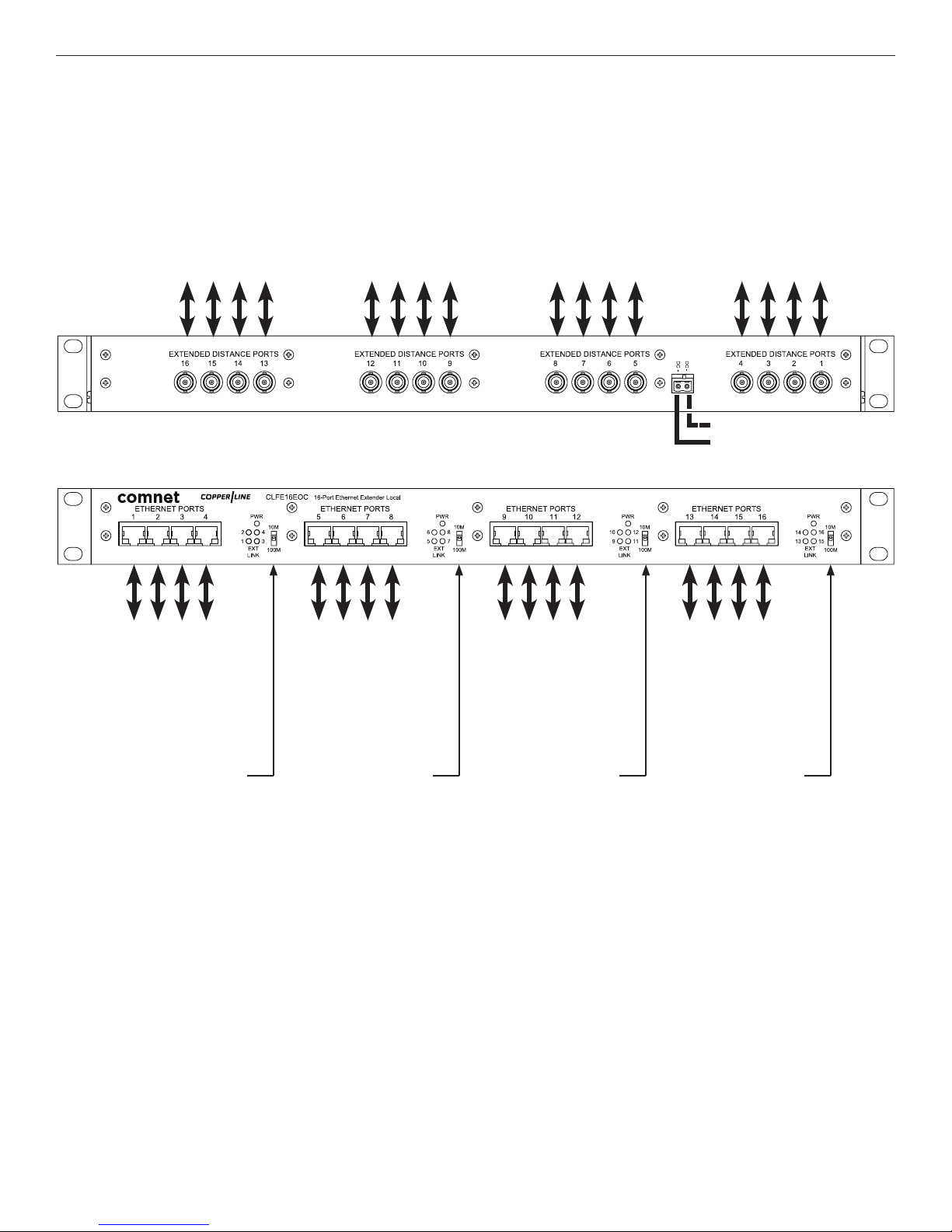
FIGURE 9 – CLFE16EOC MULTICHANNEL RACK COAX UNITS
CH16 EXT DISTANCE
CH15 EXT DISTANCE
CH14 EXT DISTANCE
CH13 EXT DISTANCE
CH12 EXT DISTANCE
CH11 EXT DISTANCE
CH10 EXT DISTANCE
CH9 EXT DISTANCE
CH8 EXT DISTANCE
CH7 EXT DISTANCE
CH6 EXT DISTANCE
CH5 EXT DISTANCE
CH4 EXT DISTANCE
CH3 EXT DISTANCE
CH2 EXT DISTANCE
CH1 EXT DISTANCE
Black w/ White Stripe (DC–)
Black (DC+)
Operating Power: 9 to 15 VDC
Power Consumption: 20W
CH1 ETHERNET
CH2 ETHERNET
CH3 ETHERNET
CH4 ETHERNET
Data rate DIP switch
See Installation
Instructions, Step 1
TECH SUPPORT: 1.888.678.9427
CH5 ETHERNET
CH6 ETHERNET
CH7 ETHERNET
CH8 ETHERNET
Data rate DIP switch
See Installation
Instructions, Step 1
CH9 ETHERNET
CH10 ETHERNET
CH11 ETHERNET
CH12 ETHERNET
Data rate DIP switch
See Installation
Instructions, Step 1
CH13 ETHERNET
CH14 ETHERNET
CH15 ETHERNET
CH16 ETHERNET
Data rate DIP switch
See Installation
Instructions, Step 1
INS_CLFE(X)EO(C,U)_REV– 10/27/11 PAGE 6
Page 7

INSTALLATION AND OPERATION MANUAL CLFE(X)EO(C,U) SERIES
FIGURE 10 – CLFE16EOU MULTICHANNEL RACK UTP UNITS
CH16 EXT DISTANCE
CH15 EXT DISTANCE
CH14 EXT DISTANCE
CH13 EXT DISTANCE
CH12 EXT DISTANCE
CH11 EXT DISTANCE
CH10 EXT DISTANCE
CH9 EXT DISTANCE
CH8 EXT DISTANCE
CH7 EXT DISTANCE
CH6 EXT DISTANCE
CH5 EXT DISTANCE
CH4 EXT DISTANCE
CH3 EXT DISTANCE
CH2 EXT DISTANCE
CH1 EXT DISTANCE
Black w/ White Stripe (DC–)
Black (DC+)
Operating Power: 9 to 15 VDC
Power Consumption: 20W
CH1 ETHERNET
CH2 ETHERNET
CH3 ETHERNET
CH4 ETHERNET
Data rate DIP switch
See Installation
Instructions, Step 1
Wire pair DIP switch
See Installation
Instructions, Step 2
TECH SUPPORT: 1.888.678.9427
CH5 ETHERNET
CH6 ETHERNET
CH7 ETHERNET
CH8 ETHERNET
Data rate DIP switch
See Installation
Instructions, Step 1
Wire pair DIP switch
See Installation
Instructions, Step 2
CH9 ETHERNET
CH10 ETHERNET
CH11 ETHERNET
CH12 ETHERNET
Data rate DIP switch
See Installation
Instructions, Step 1
Wire pair DIP switch
See Installation
Instructions, Step 2
CH13 ETHERNET
CH14 ETHERNET
CH15 ETHERNET
CH16 ETHERNET
Data rate DIP switch
See Installation
Instructions, Step 1
Wire pair DIP switch
See Installation
Instructions, Step 2
INS_CLFE(X)EO(C,U)_REV– 10/27/11 PAGE 7
Page 8

INSTALLATION AND OPERATION MANUAL CLFE(X)EO(C,U) SERIES
APPLICATION DIAGRAMS
Note: Coaxial applications use CLFE(X)EOC modules; UTP applications use CLFE(X)EOU modules.
PoE Pass-Through Mode
PoE
Ethernet Switch
or Midspan
Non-PoE Mode
Ethernet
Switch
Power Power Power
Multichannel PoE Application
Power
PoE
Ethernet Switch
or Midspan
Local Remote
CLFE1EO(C,U) CLFE1EO(C,U)
Local Remote
CLFE1EO(C,U) CLFE1EO(C,U)
Local Remote
CLFE1EO(C,U)
CLFE4EO(C,U)
CLFE1EO(C,U)
CLFE4EO(C,U)
Power
CLFE8EO(C,U)
CLFE1EO(C,U)
Ethernet Connection
Extended Connection
PoE Power
PoE Camera
IP Camera
PoE Camera
PoE Camera
PoE Camera
PoE Camera
PoE Camera
Multichannel Non-PoE Application
Ethernet
Switch
IMPORTANT NOTE. PLEASE READ. The applications are
shown as general representations only and are not intended
to show detailed network topologies. Your actual network
will differ, requiring changes or perhaps additional network
equipment to accommodate the systems as illustrated.
Please contact ComNet’s Design Center to discuss your
specific requirements.
Power
Power
Local Remote
Power Power
Power Power
CLFE16EO(C,U)
Power Power
Power Power
Power Power
CLFE1EO(C,U)
CLFE1EO(C,U)
CLFE1EO(C,U)
CLFE1EO(C,U)
CLFE4EO(C,U)
CLFE1EO(C,U)
CLFE1EO(C,U)
PoE Camera
PoE Camera
IP Camera
IP Camera
IP Camera
Power
IP Camera
IP Camera
IP Camera
TECH SUPPORT: 1.888.678.9427
INS_CLFE(X)EO(C,U)_REV– 10/27/11 PAGE 8
Page 9

INSTALLATION AND OPERATION MANUAL CLFE(X)EO(C,U) SERIES
INSTALLATION INSTRUCTIONS
1 - SET 10/100 SWITCH
Locate the 10/100 data rate DIP switch on the unit.
Set the data rate according to bandwidth required. The default setting for the data rate DIP switch is 100Mbps.
NOTE: The data rate must be set the same on both the local and remote units.
2 - SET WIRE PAIR DIP SWITCHES (UTP MODELS ONLY, FOR COAX MODELS SKIP TO STEP 3)
Locate the wire pair DIP switch on the unit.
Set the pair according to number of twisted wire pairs used (1 or 4). The default setting for the wire pair DIP switch is 4 pair.
NOTE: The number of pairs selected must be set the same on both the local and remote units. PoE Pass-Through mode
is only available in 4-pair mode and requires a PD device connected to the ComNet remote unit to operate.
3 - SET LOCAL/REMOTE SWITCHES (1 AND 4 CHANNEL UNITS ONLY, FOR RACK UNITS SKIP TO STEP 4)
Locate the Local/Remote Dip switch and set to “LC” at the head end or “RM” at the camera end.
Locate the Local/Remote push button switch (coax units only), and set to the same setting as the dip switch.
The factory setting for these switches is “RM”.
The CLFE8EO(C,U) and CLFE16EO(C,U) units are preconfigured as Local devices.
4 - CONNECT EXTENDED WIRING
Connect Extended Distance Port to field wiring.
5 - CONNECT NETWORK WIRING
Using CAT5/5e, connect Local unit to network and Remote unit to camera.
6 - CONNECT POWER
Connect power to unit per the following table:
Table 1 – Power Connections per Use Case
Unit Local Power Pass-Through PoE
CLFE1EO(C,U) 9 to 36 VDC or 18 to 32 VAC No external power required
CLFE4EO(C,U) 9 to 15 VDC (9 VDC† when in a C1 or C2 rack)
CLFE8EO(C,U)
CLFE16EO(C,U)
†
Contact ComNet pre-sales support, or refer to the appropriate installation and operation manual when configuring and specifying power for a deployment.
9 to 15 VDC
7 - VERIFY FUNCTIONALITY
See LED table below and Troubleshooting Guide if corrective action is needed. See figures beginning on page 6 for LED
configurations for each model.
Table 2 – Indicating LEDs
PWR Ethernet Link Ethernet Activity EXT LNK
GREEN Power Applied – Activity Detected 10Mbps
YELLOW – Link Established – 100Mbps
OFF Power Off No Link No Activity No Link
Ethernet
Activity
Ethernet
Link
TECH SUPPORT: 1.888.678.9427
EXT Link Power
CLFE1EOU Only
INS_CLFE(X)EO(C,U)_REV– 10/27/11 PAGE 9
Page 10

INSTALLATION AND OPERATION MANUAL CLFE(X)EO(C,U) SERIES
APPLICATION NOTES
1 Mixed PoE and Non-PoE systems can be implemented.
2 All Non-PoE systems require local power.
3 PoE powered operation requires that a PoE Camera be connected, and that the camera power requirements are understood.
4 Multiple Channel units (CLFE4EO(C,U), CLFE8EO(C,U), CLFE16EO(C,U) require 9 to 15 VDC for proper operation. The
CLFE4EO(C,U) can be used in a C1, C2, or C3.
5 Single Channel units (CLFE1EO(C,U)) require power for all Non-PoE applications. Local power can be used in PoE application to
minimize PoE consumption.
6 Lower data rates generally provide longer operating distances.
7 Rack units (CLFE8EO(C,U), CLFE16EO(C,U)) are pre-configured for Local (LC) and have no configurable Local/Remote switch. Any
unit connected to one of these rack units via an extended distance port must be configured as Remote (RM) for proper operation.
TABLE 3 – APPROXIMATE MAXIMUM EXTENDED DISTANCES
1
Media COAX - RG59/U UTP - 4 pair UTP - 1 pair
Camera Data Rate
Non-PoE Camera
PoE CLASS2 Camera (6.5W)
1
1
PoE CLASS3 Camera(13W)1
(10W in Pass-Through mode)
1
Distance figures are based on a 50V PSE PoE power source, and external power supplies for the extenders. Distance figures are obtained using
in-house testing mirroring installations. Factors such as coaxial/copper cable quality, the number of connectors/splices in the cable run, the use
of PoE, and environmental conditions encountered within the installation may affect the actual transmission distance, and should be taken into
consideration. Due to advanced negotiation signaling required in IEEE 802.3at applications, Pass-through applications are limited to IEEE 802.3af PD
devices only.
² PoE over extended distance is not available in 1 Pair mode. Remote PoE injection is required for this case.
10M 100M 10M 100M 10M 100M
5,000 ft
1,524 m
3,000 ft
914 m
750 f t
228 m
2,000 ft
610 m
2,000 ft
610 m
750 f t
228 m
3,000 ft
914 m
3,000 ft
914 m
750 f t
228 m
2,000 ft
610 m
2,000 ft
610 m
750 f t
228 m
N/A N/A
3,000 ft
914 m
N/A N/A
3,000 ft
914 m
TABLE 4 – TROUBLESHOOTING GUIDE
Problem Steps to Take
Indicating LEDs not lighting Non-PoE: Check that power is properly applied to the unit
No Communication
Bad Video
PoE Not Supplied to PD Make sure camera is IEEE 802.3af rated, PoE Source switch is set properly, and the extended dis tance is within specifications (see Table
PoE: Check that PoE camera is connected, PoE source is enabled.
Check Ethernet Link LEDs, Ex tended Link LEDs, All Connections, Local/Remote and 10/100 switches are set properly. Verify that Local
units are installed at the head end and that Remote units are installed in the field.
Make sure Data Rate Switch is set properly, and the extended distance is within specifications (see Table 3 – Approximate
Maximum Extended Distances).
3 – Approximate Maximum Extended Distances).
Units not reaching
estimated max dist ances
over COAX or CAT5/UTP
Check extended distance cable and connections. Try connection on a shor t cable to eliminate possibility of fault y cabling.
Check that the ex tended distance wire is connec ted to Extended Dis tance Port.
Verify that there is no additional equipment (e.g. surge protec tor) on the Extended Link. The cable should be continuous from end to end,
with no ac tive components.
TECH SUPPORT: 1.888.678.9427
INS_CLFE(X)EO(C,U)_REV– 10/27/11 PAGE 10
Page 11

INSTALLATION AND OPERATION MANUAL CLFE(X)EO(C,U) SERIES
PRODUCT DIMENSIONS
The CLFE1EO(C,U) is supplied as a standalone/surface mount (small size) module.
The CLFE4EO(C,U) is supplied as a standalone/surface/rack (ComFit) module.
The CLFE8EO(C,U) and CLFE16EO(C,U) are supplied as 19″ wide rack units for standalone or rack installation.
FIGURE A
Dimensions are for a small size module
4.19cm
[1.65in]
8.38cm
[3.3in]
2.7cm
[1.06in]
0.8cm
[0.31in]
0.4cm
[0.16in]
0.62cm
[0.24in]
6.37cm
[2.50in]
FIGURE B
Dimensions are for a ComFit module
13.2cm
[5.2in]
11.9cm
[4.7in]
7.5cm
0.63cm
[0.25in]
2.75cm
[1.1in]
[2.9in]
15cm
[5.9in]
FIGURE C
Dimensions are for a 19″ Rack Unit
1.9cm
[0.75in]
4.37cm
[1.72in]
TECH SUPPORT: 1.888.678.9427
44.45cm
[17.50in]
48.26cm
[19.0in]
1.9cm
[0.75in]
15.44cm
[6.08in]
INS_CLFE(X)EO(C,U)_REV– 10/27/11 PAGE 11
Page 12

INSTALLATION AND OPERATION MANUAL CLFE(X)EO(C,U) SERIES
INSTALLATION CONSIDERATIONS
These units are supplied as Standalone/Rack mounted module. Units should be installed in dry locations protected from extremes of temperature and
humidity.
WARNING: Unit is to be used with a Listed Class 2 power supply.
IMPORTANT SAFEGUARDS:
A) Elevated Operating Ambient - If installed in a closed or multi-unit rack assembly, the operating ambient temperature of the rack environment may be greater than
room ambient. Therefore, consideration should be given to installing the equipment in an environment compatible with the maximum ambient temperature (Tma)
specified by the manufacturer.
B) Reduced Air Flow - Installation of the equipment in a rack should be such that the amount of air flow required for safe operation of the equipment is not compromised.
3 CORPORATE DRIVE
8 TURNBERRY PARK ROAD
© 2014 Communica tion Network s. All Rights R eserved. “C omNet,” the “Com Net Logo,” “Coppe rLine,”
and the “C opperLine Log o” are register ed trademark s of Communicat ion Network s.
|
DANBURY, CONNECTICUT 06810
|
GILDERSOME
|
MORLEY
|
|
USA
T: 203.796.5300
|
LEEDS, UK LS27 7LE
|
F: 203.796.5303
|
T: +44 (0)113 307 6400
|
TECH SUPPORT: 1.888.678.9427
|
F: +44 (0)113 253 7462
INS_CLFE(X)EO(C,U)_REV– 10/27/11 PAGE 12
|
|
INFO@COMNET.NET
INFO-EUROPE@COMNET.NET
 Loading...