

Page 1

INSTALLATION AND OPERATION MANUAL
CLFE4US1TPC
4-PORT ETHERNET SWITCH WITH UTP/TWISTED COPPER
AND COAXIAL CABLE EXTENDER
Important Safety Warning:
Read and keep these directions
Heed all warnings
Follow all instructions
Do not use this apparatus near water
Clean only with a dry cloth
Install in accordance with the manufacturer’s
instructions
This installation should be made by a qualified
service person and should conform to all local codes
See further safety instructions on Page 7
The ComNet™ CopperLine® CLFE4US1TPC is an unmanaged switch that combines
four individual Ethernet data channels over a single standard COAX or UTP cable.
Symmetric bandwidth assures full bandwidth transmission is maintained over the
entire operational distance for both uploads and downloads with virtually zero packet
loss. Bandwidth assurance provides the ability to transmit multiple cameras on
single camera runs with no information loss. Combined with the CopperLine CLFE(X)
COAX series or CLFE(X)UTP series multi-port extenders up to 64 cameras can be
transmitted to a central location on just 16 cables.
The CLFE4US1TPC can be powered using standard camera 12 VDC or 24 VAC power
supplies. It also can be powered by PoE eliminating the need for remote site extra
cost power supplies.
Type tested under NEMA-TS2 environmental standards for extended temperature
operation from -40C° to +75C°. Certified for use with high-bandwidth megapixel
or HD IP cameras and tested to network packet performance standards along with
major manufacturer compatibility testing.
Fixed managed L2 functions include 802.1p Qos, support of 2k MAC addressing,
learning and aging and a non-blocking switch fabric.
Packaged in a rugged aluminum housing, these units are designed for desktop or standalone mounting. See Figure A on Page 5 for mounting instructions.
See Figures 1 – 5 for complete installation details.
INS_CLFE4US1TPC_REV–
10/11/11
PAGE 1
Page 2

INSTALLATION AND OPERATION MANUAL CLFE4US1TPC
FIGURE 1 – CLFE4US1TPC
CAT5/6
BLACK
Coax
UTP
BLACK WITH WHITE STRIPE
12 VDC, 24 VAC
or POE @ 250 mA, max.
FIGURE 2 – POSSIBLE ETHERNET CONFIGURATION
Multiple Configurations are possible. Consult ComNet Design Center.
CLFE16UTP
CLFE16UTP
NVR
Network Switch
Cat-5
≤3,000ft (914m) Cat-5
≤5,000ft (1524m) Coax
PoE Switch
CNGE2FE24MSPOE
CopperLine
Extender
OR
Coax or UTP
PoE
CLFE4US1TPC
≤328ft
(100m) C at-5
CLFE4US1TPC
≤328ft
(100m) C at-5
IP Cameras
IP Cameras
IP Cameras
IP Cameras
TECH SUPPORT: 1.888.678.9427
INS_CLFE4US1TPC_REV–
10/11/11
PAGE 2
Page 3
INSTALLATION AND OPERATION MANUAL CLFE4US1TPC
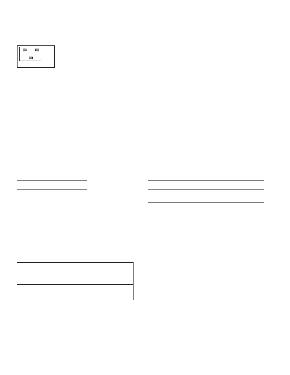
IP CAmERA-ENd
INSTALLATION (CLFE4US1TPC)
S1 S2 S3
Off
On
Set the S1 10/100BaseT dip switch to the appropriate rate based on the required maximum data rate and
maximum distance. OFF = 10BaseT; ON = 100BaseT
Set the S2 Master/Slave dip switch to ON for “Master” mode.
For Extended UTP connection, set the S3 1- or 4-pair dip switch ON for 1-pair or OFF for 4-pair operation.
For Extended Coax connection, set the S3-1 switch ON.
For systems not utilizing PoE, connect the 12V Power Supply to the power connector of the CLFE4US1TPC. A power adapter
connector is provided to simplify connection.
Connect up to 4 IP cameras to the 10/100BaseT Ethernet port(s) of the CLFE4US1TPC using standard Cat5/6 cables, each 100m
length (max).
The link LED on the 10/100 connector should be “ON” to indicate proper connection between the camera and the CLFE4US1TPC.
Note: While each standard Ethernet port can operate at either 10 or 100 Mbps, the extended port is 100Mbps max. The recommended total
bandwidth limitation should not exceed 54Mbps and is above the upper limit for transmitting four cameras.
FIGURE 3 – POWER LEd INdICATORS FIGURE 4 – EXTENdEd LEd INdICATORS
POWER
TRAFFIC 10/100BaseT
RED
OFF
Power is on
Power is off
FIGURE 5 – ETHERNET LEd INdICATORS
TRAFFIC LINK
GREEN
YELLOW
OFF
Flashing – Connection is
OK with traffic
– Connection is OK
No connection No connection
–
GREEN
YELLOW
ORANGE
OFF
– Connection is OK,
10BaseT mode
Flashing, Traffic present –
– Connection is OK,
100BaseT mode
No traffic –
TECH SUPPORT: 1.888.678.9427
INS_CLFE4US1TPC_REV–
10/11/11
PAGE 3
Page 4
MECHANICAL INSTALLATION INSTRUCTIONS
• Read and keep these directions.
• Heed all warnings.
• Follow all instructions.
• Do not use this apparatus near water.
• Clean only with a dry cloth.
• Install in accordance with the manufacturer’s instructions.
• This installation should be made by a qualified service person and should
conform to all local codes.
• DO NOT bundle UTP or Coax signals in the same conduit as high-voltage
wiring.
• To reduce the risk of fire or electrical shock, do not expose these products
to rain, moisture, dripping or splashing.
• No objects filled with liquids, such as vases, shall be placed on the
equipment.
• DO NOT install the unit in a place where the operating ambient
temperature exceeds 75ºC.
• Make sure that the external power supply output voltage is in the
recommended range.
• Do not install near any heat sources such as radiators, heat registers, stoves
or other apparatus (including DVRs) that produce heat.
• Protect the power cord from being walked on or pinched, particularly at
the power source, convenience receptacles and the point where they exit
from the apparatus.
• Only use attachments/accessories specified by the manufacturer.
• Unplug this apparatus during lightning storms or when unused for long
periods of time.
• Refer all servicing to qualified service personnel. Servicing is required
when the apparatus has been damaged in any way, such as when a power
supply cord or plug is damaged, liquid has been spilled, objects have
fallen inside the apparatus, the apparatus has been exposed to rain or
moisture, do not operate normally or has been dropped.
• The main plus is used as the disconnect device and shall remain readily
operable.
WARNING: To reduce the risk of fire or electric shock, do not expose this
apparatus to rain or moisture. This apparatus shall not be
exposed to dripping or splashing and no objects filled with
liquids, such as vases shall be placed on the apparatus.
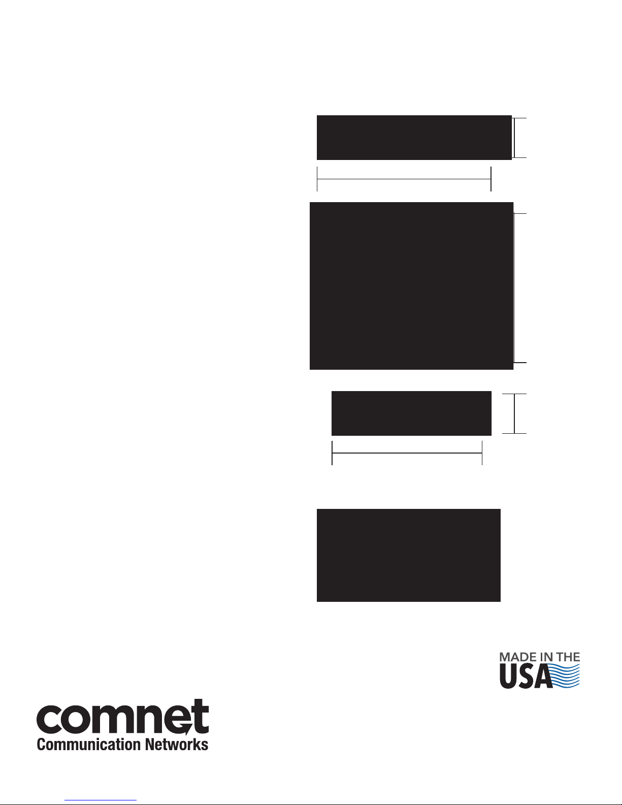
FIGURE A
Dimensions are for the CLFE4US1TPC standalone ComNet module
1.2" (3cm)
5.125" (13cm)
4.54"
(11.5cm)
1.2" (3cm)
4.54" (11.5cm)
WARNING: This apparatus is a Class I product. This product must be
connected to a mains socket outlet through an AC to DC
power supply.
WARNING: The mains plug is used as the disconnect device and shall
remain readily operable.
WARNING: For non-PoE applications, unit is to be connected to a mains
socket outlet through a Listed Class I power supply rated
12 VDC or 24 VAC.
© 2012 Communications Ne tworks Cor poration. All Rights Reser ved. “ComNet ” and the “ComNet L ogo” are registered trademarks of C ommunication Networ ks, LLC.
3 CORPORATE DRIVE | DANBURY, CT 06810 | USA
T: 203.796.5300 | F: 203.796.5303 | TECH SUPPORT: 1.888.678.9427 | INFO@COMNET.NET
8 TURNBERRY PARK ROAD | GILDERSOME | MORLEY | LEEDS, UK LS27 7LE
T: +44 (0)113 307 6400 | F: +44 (0)113 253 7462 | INFO-EUROPE@COMNET.NET
INS_CLFE4US1TPC_REV–
10/11/11
PAGE 4
 Loading...