

Page 1
INSTALLATION AND OPERATION MANUAL
CLFE4+2SMS[POE](C,U) Series
10/100TX DROP/INSERT/REPEAT 4TX/2EX
SELF-MANAGED SWITCH WITH POE+
This manual serves the following
ComNet Model Numbers:
CLFE4+2SMSC
CLFE4+2SMSU
CLFE4+2SMSPOEC
CLFE4+2SMSPOEU
The ComNet CLFE4+2SMS[POE](C,U) is a six-port Ethernet switch with add/drop/repeat
functionality and provides 4 copper ports operating at 10/100Mbps and is designed to
combine four electrical ports along with the incoming Cat5, UTP or Coax CopperLine®
extension port into a further CopperLine extension port that forwards this data to
the next CopperLine network device. There is no programming required to use this
product. The ComNet CLFE4+2SMS(C,U) comes pre-programmed, preventing network
video flooding with DIP switch selection of the first CopperLine port as an uplink or as
an unmanaged switch. Ports 1–4 of the CLFE4+2SMSPOE(C,U) can supply up to thirty
(30) watts of Power over Ethernet (PoE) and incorporate PoE+ features based on the
IEEE 802.3at standard. It is “Plug-and-Play”.
INS_CLFE4+2SMS[POE](C,U)_REV– 10/27/11 PAGE 1TECH SUPPORT: 1.888.678.9427
Page 2
INSTALLATION AND OPERATION MANUAL CLFE4+2SMS[POE](C,U) SERIES
INSTALLATION AND OPERATION MANUAL CLFE4+2SMS[POE](C,U) SERIES
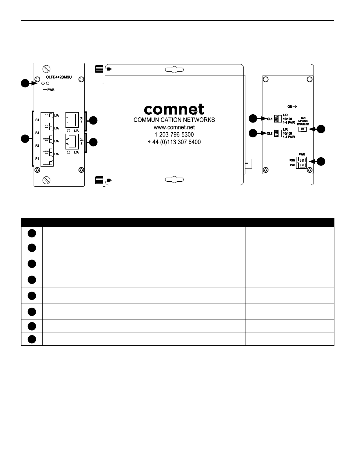
CLFE4+2SMSU PHYSICAL DESCRIPTION
Figure 1 – Physical Features of CLFE4+2SMSU
1
3
2
4
5
6
Table 1 – Physical Feature Descriptions
Call-out Description Manual Reference
1
Power Indicating LED (Unlabeled LED Reserved for Future Use) See Table 3 - Indicating LEDs
2
10/100 TX RJ-45 Ports 1 through 4 and Link/Activity (L/A) Indicating LEDs
3
Channel 1 Extended Distance over UTP RJ-45 Port and Link/Activity (L/A) Indicating LED
4
Channel 2 Extended Distance over UTP RJ-45 Port and Link/Activity (L/A) Indicating LED
Channel 1 Extended Distance over UTP Port DIP Switches for Local/Remote Operation, Data Speed,
5
and Wire Pairs
Channel 2 Extended Distance over UTP Port DIP Switches for Local/Remote Operation, Data Speed,
6
and Wire Pairs
See Installation Instructions, Step 5
See Table 3 - Indicating LEDs
See Installation Instructions, Step 4
See Table 3 - Indicating LEDs
See Installation Instructions, Step 4
See Table 3 - Indicating LEDs
See Installation Instructions, Steps 1 – 3
See Installation Instructions, Steps 1 – 3
7
8
7
Channel 1 Extended Distance over UTP Uplink DIP Switch See Installation Instructions, Step 6
8
Power Connections See Installation Instructions, Step 7
TECH SUPPORT: 1.888.678.9427
INS_CLFE4+2SMS[POE](C,U)_REV– 10/27/11 PAGE 2
Page 3
INSTALLATION AND OPERATION MANUAL CLFE4+2SMS[POE](C,U) SERIES
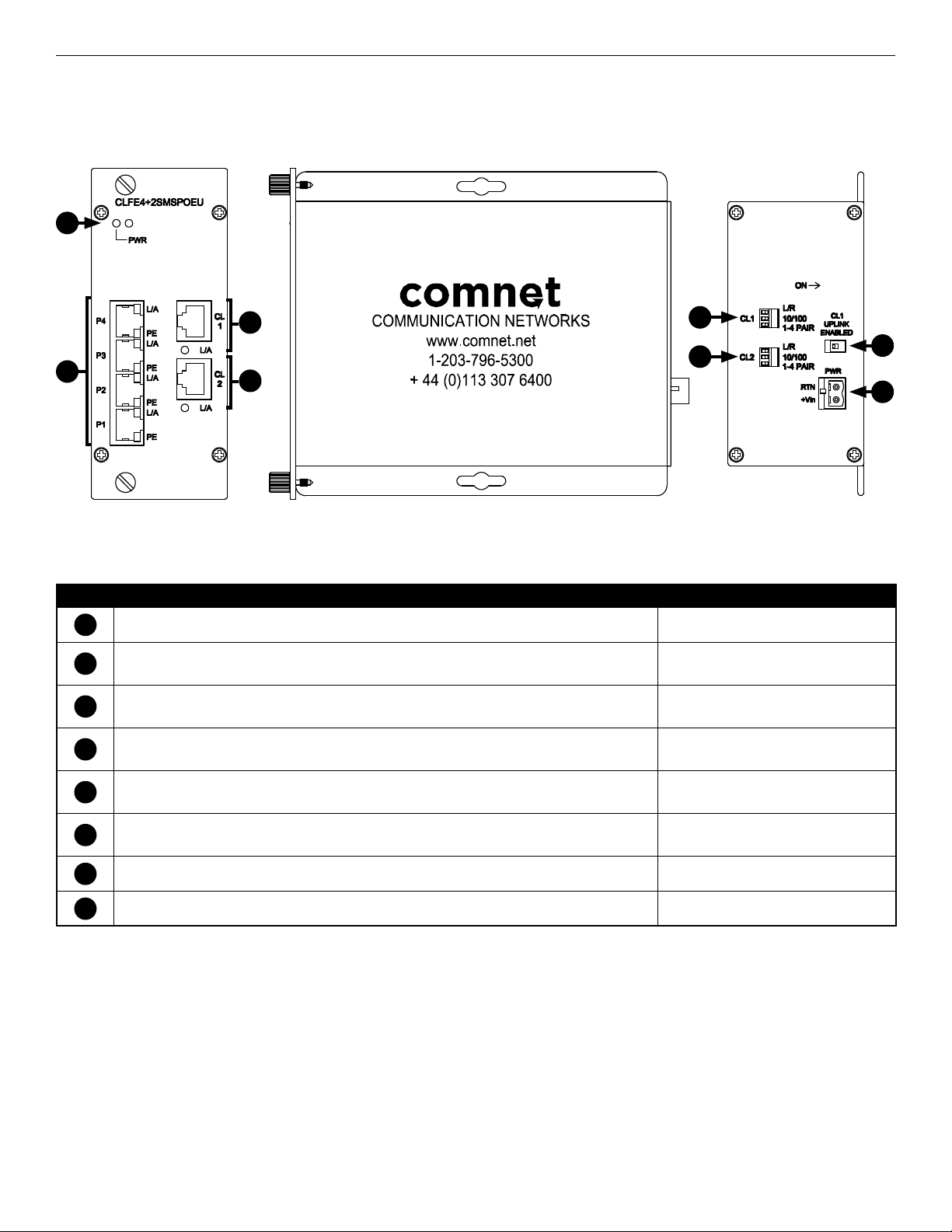
CLFE4+2SMSPOEU PHYSICAL DESCRIPTION
Figure 1 – Physical Features of CLFE4+2SMSPOEU
1
3
2
4
5
6
Table 1 – Physical Feature Descriptions
Call-out Description Manual Reference
1
Power Indicating LED (Unlabeled LED Reserved for Future Use) See Table 3 - Indicating LEDs
2
10/100 TX RJ-45 Ports 1 through 4 and Link/Activity (L/A) Indicating LEDs
3
Channel 1 Extended Distance over UTP RJ-45 Port and Link/Activity (L/A) Indicating LED
4
Channel 2 Extended Distance over UTP RJ-45 Port and Link/Activity (L/A) Indicating LED
Channel 1 Extended Distance over UTP Port DIP Switches for Local/Remote Operation, Data Speed,
5
and Wire Pairs
Channel 2 Extended Distance over UTP Port DIP Switches for Local/Remote Operation, Data Speed,
6
and Wire Pairs
See Installation Instructions, Step 5
See Table 3 - Indicating LEDs
See Installation Instructions, Step 4
See Table 3 - Indicating LEDs
See Installation Instructions, Step 4
See Table 3 - Indicating LEDs
See Installation Instructions, Steps 1 – 3
See Installation Instructions, Steps 1 – 3
7
8
7
Channel 1 Extended Distance over UTP Uplink DIP Switch See Installation Instructions, Step 6
8
PoE Power Connections See Installation Instructions, Step 7
TECH SUPPORT: 1.888.678.9427
INS_CLFE4+2SMS[POE](C,U)_REV– 10/27/11 PAGE 3TECH SUPPORT: 1.888.678.9427
Page 4

INSTALLATION AND OPERATION MANUAL CLFE4+2SMS[POE](C,U) SERIES
Installation Instructions
1 - SET DATA RATE DIP SWITCHES
Locate the 10/100 data rate DIP switch on the unit.
Set the data rate according to bandwidth required.
NOTE: The data rate must be set the same on both the local and remote units.
2 - SET WIRE PAIR DIP SWITCHES (UTP MODELS ONLY, FOR COAX MODELS SKIP TO STEP 3)
Locate the wire pair DIP switch on the unit.
Set the pair according to number of twisted wire pairs used (1 or 4).
NOTE: The number of pairs selected must be set the same on both the local and remote units.
Figure 2 – One-Pair Pin Assignment
For 1-pair mode, use the first pair of pins (pins 1 and 2) of the
“Extended Ethernet” RJ- 45 port.
3 - SET LOCAL/REMOTE DIP SWITCHES
Set the Local/Remote switch to Local (LC) for Local (head end) devices or Remote (RM) for Remote (field end) devices.
4 - SET CL1 UP LINK ENABLED DIP SWITCH
Set the Up Link switch to the “ON” position to enable Uplink port features.
5 - CONNECT EXTENDED WIRING
Connect Extended Distance Port to field wiring.
6 - CONNECT NETWORK WIRING
Using Cat5/5e, connect Local unit to network and Remote unit to camera.
7 - CONNECT POWER
Connect power to unit per the following table.
NOTE: Remove Electrical Connector for Rack Mount Units
Table 2 – Power Connections per Use Case
Non-PoE PoE Models Only
Operating Voltage 12 to 24 VDC (9 VDC
†
when in C1 or C2 Rack)
†
48 to 56 VDC
Use Power Connectors RTN and +Vin RTN and +Vin
†
Contact the ComNet Design Center, or refer to the appropriate installation and operation manual when configuring and specifying power for a deployment.
8 - VERIFY FUNCTIONALITY
See LED table below and Troubleshooting Guide if corrective action is needed.
Table 3 – Indicating LEDs
PWR Link (Ethernet Port) Activity (Ethernet Port) L/A (CH 1 or 2) POE (PoE Models Only)
SOLID Power Applied Link Detected – Link Detected Supplying PoE to PD(s)
BLINKING – – Data Activity Data Activity –
OFF Power Off No Link – No Link Not Supplying PoE to PD(s)
TECH SUPPORT: 1.888.678.9427
INS_CLFE4+2SMS[POE](C,U)_REV– 10/27/11 PAGE 4
Page 5

INSTALLATION AND OPERATION MANUAL CLFE4+2SMS[POE](C,U) SERIES
Table 4 – Approximate Maximum Extended Distances¹
Media COAX - RG59/U UTP - 1 pair UTP - 4 pair
Extended Port Data Rate 10M 100M 10M 100M 10M 100M
Extended Distance
1
Distance figures are obtained using in-house testing mirroring installations. Factors such as coaxial/copper cable quality, the number of connectors/
splices in the cable run, the use of PoE, and environmental conditions encountered within the installation may af fect the actual transmission
distance, and should be taken into consideration.
1
5,000 ft
1,524 m
Table 5 – Troubleshooting Guide
Problem Steps to Take
Indicating LEDs not lighting Check that power is properly applied to the unit using the correct connector pair.
No Communication Check Ethernet Link LEDs, Extended Link LEDs, All Connections, Local/Remote switch is set properly.
Verify that Local units are installed at the head end and that Remote units are installed in the field.
Verify that the Data Rate switches are set to the same data rate on both the Local and Remote units.
Bad Video or Data Make sure Data Rate and 1/4 Pair Switches are set properly, and the extended distance is within specifications (see Table
4 – Approximate Maximum Extended Distances).
Units not reaching estimated max
distances over COAX or UTP
Check extended distance cable and connections. Try connection on a short cable to eliminate possibility of faulty cabling.
Check that the extended distance wire is connected to Extended Distance Port.
Verify that there is no additional equipment (e.g. surge protector) on the Extended Link. The cable should be continuous from
end to end, with no active components.
2,000 ft
610 m
3,000 ft
914 m
1,000 ft
305 m
3,000 ft
914 m
2,000 ft
610 m
Figure 3 – DIP Switch Settings Table 6 – DIP Switch Settings
DIP Switch Setting Effect
L/R Unit will operate as remote / field Unit will operate as local / head-end
CL1
10/100 100 Mbps Data Speeds 10 Mbps Data Speeds
1 - 4 PAIR 1 Pair Twisted Wires 4 Pair Twisted Wires
L/R Unit will operate as remote / field Unit will operate as local / head-end
10/100 100 Mbps Data Speeds 10 Mbps Data Speeds
CL2
1 - 4 PAIR
CL1 UP LINK Enabled Disabled
On Off
1 Pair Twisted Wires
4 Pair Twisted Wires
TECH SUPPORT: 1.888.678.9427
INS_CLFE4+2SMS[POE](C,U)_REV– 10/27/11 PAGE 5
Page 6

INSTALLATION AND OPERATION MANUAL CLFE4+2SMS[POE](C,U) SERIES
INSTALLATION AND OPERATION MANUAL CLFE4+2SMS[POE](C,U) SERIES
Application notes
1 Mixed PoE and Non-PoE systems can be implemented.
2 Lower data rates generally provide longer operating distances.
Figure 4 – Typical Application
CLFE4+2SMSC
12VDC
CLFE1EOC
Power
E
6 5
1 2
3 4
Power
CLFE4+2SMSPOEC
65
1 2 3
4
PoE
Legend
CAT5e/6 Cable
PoE Power
Coax/UTP
Power
E E
E EE EE E
Figure 5 – Application Diagram With Multicast Traffic
IGMP Enabled, Uplink enabled on the units
Up-layer Network
CL(X)-SFP CL(X)-SFP
CL(X)-SFP CL(X)-SFP
CL1
CL2
CL1
CLFE4+2SMSPOE(C,U)
CLFE4+2SMS(C,U)
PoE Devices
Figure 6 – Application Diagram Without Multicast Traffic
IGMP Disabled, Uplink disabled on the units.
Up-layer Network
CNGE3FE7MS2
CL1
CLFE4+2SMS(C,U)
CL1
CLFE4+2SMS(C,U)CLFE4+2SMS(C,U)
CL2
CNGE3FE7MS2
CL1
PoE Camera
Connections
on Ports P1-P4
TECH SUPPORT: 1.888.678.9427
CL1
CLFE4+2SMS(C,U)
PC Connections
on Ports P1-P4
INS_CLFE4+2SMS[POE](C,U)_REV– 10/27/11 PAGE 6
Page 7

INSTALLATION AND OPERATION MANUAL CLFE4+2SMS[POE](C,U) SERIES
INSTALLATION CONSIDERATIONS
These units are supplied as Standalone/Rack mounted module. Units
should be installed in dry locations protected from extremes of
temperature and humidity.
WARNING: Unit is to be used with a Listed Class 2 power supply. Although
the units may be mounted inside a ComNet rack the PoE models cannot be
powered from the built-in rack PSU; they must be powered by an external
48-56VDC PSU.
IMPORTANT SAFEGUARDS:
A) Elevated Operating Ambient
assembly, the operating ambient temperature of the rack environment
may be greater than room ambient. Therefore, consideration should be
given to installing the equipment in an environment compatible with
the maximum ambient temperature (Tma) specified by the manufacturer.
B) Reduced Air Flow - Installation of the equipment in a rack should be such
that the amount of air flow required for safe operation of the equipment
is not compromised.
- If installed in a closed or multi-unit rack
FIGURE A
Dimensions are for a ComFit module
3 CORPORATE DRIVE
8 TURNBERRY PARK ROAD
© 2016 Communicat ion Network s. All Rights R eserved. “C omNet,” the “Com Net Logo,” “Copper Line,” and the “Copp erLine Logo” ar e registered t rademarks o f Communication N etworks.
|
DANBURY, CONNECTICUT 06810
|
GILDERSOME
|
MORLEY
|
|
USA
T: 203.796.5300
|
LEEDS, UK LS27 7LE
|
F: 203.796.5303
|
T: +44 (0)113 307 6400
|
TECH SUPPORT: 1.888.678.9427
|
F: +44 (0)113 253 7462
INS_CLFE4+2SMS[POE](C,U)_REV– 10/27/11 PAGE 7TECH SUPPORT: 1.888.678.9427
|
|
INFO@COMNET.NET
INFO-EUROPE@COMNET.NET
 Loading...