

Page 1
INSTALLATION AND OPERATION MANUAL
CLEK41EOC
COPPERLINE® VALUE KIT: POINT-TO-MULTIPOINT
ETHERNET-OVER-COAX EXTENDER
This manual serves the following
ComNet Model Numbers:
CLEK41EOC:
1 × CLEL4EOC
4 × CLER1EO C/ M
The ComNet Value CLEK41EOC features four remote 10/100 Mbps single-channel
units and a single four-channel local unit in a pre-packaged kit. Perfect for
applications that face density challenges. The four-channel units will fit into any
ComNet product rack. The four individual small-sized remote units can be placed
up to 1,200 feet (400 meters) from the four channel local unit. Power supplies
included. A DIP Switch allows configurable selection of 10 Mbps or 100 Mbps
speed these units are simple to install. This CopperLine® Value kit provides five
units with power supplies.
Bi-color (Red/Green) LED indicators are provided for rapidly ascertaining equipment
operating status. Step 5 on Page 4 describes the LED indicators for each light on the
unit.
The CLEL4EOC four channel unit is interchangeable between stand-alone or card
mount configurations, or may be DIN-rail mounted by the addition of ComNet
model DINBKT1 or DINBKT4 adaptor plate. The CLER1EOC/M mini units are standalone, or may be DIN-rail mounted by the addition of ComNet model DINBKT4
adaptor. See Figures A and B on Page 5 for mounting instructions.
INS_CLEK41EOC_REV– 10/27/11 PAGE 1TECH SUPPORT: 1.888.678.9427
Page 2
INSTALLATION AND OPERATION MANUAL CLEK41EOC
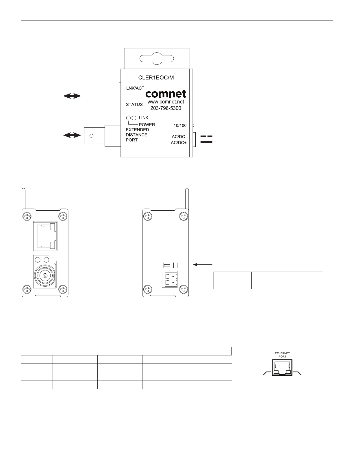
FIGURE 1 – CLER1EOC/M REMOTE MINI SINGLE CHANNEL COAX UNIT
Operating Power: 12 VDC
OR 24 VAC
Power Consumption: 1.5 W
ETHERNET
Black w/ White
EXT DISTANCE
FIGURE 2 – CLER1EOC/M REMOTE MINI SINGLE CHANNEL COAX UNIT
Stripe (AC or DC–)
Black (AC or DC+)
UP
DOWN
10/100 data rate DIP switch
Switch UP DOWN
10/100 10 Mbps 100 Mbps
See Installation Instructions for more information
Remote Mini Single Channel Coax Indicating LEDs
POWER LINK Ethernet Link Ethernet Activity
GREEN Power Applied 10Mbps – Activity Detected
YELLOW – 100Mbps Link Established –
OFF Power Off No Link No Link No Activity
Ethernet
Activity
Ethernet
Link
TECH SUPPORT: 1.888.678.9427
INS_CLEK41EOC_REV– 10/27/11 PAGE 2
Page 3

INSTALLATION AND OPERATION MANUAL CLEK41EOC
FIGURE 3 – CLFE4EOC LOCAL FOUR CHANNEL SURFACE OR RACK MOUNT COAX UNIT
CH1 ETHERNET
CH2 ETHERNET
CH3 ETHERNET
CH4 ETHERNET
CH1 EXT
DISTANCE
CH2 EXT
DISTANCE
CH3 EXT
DISTANCE
CH4 EXT
DISTANCE
Black w/ White
Stripe (DC–)
Black (DC+)
Operating Power: 9 to 15 VDC
Power Consumption: 5W
FIGURE 4 – CLFE4EOC LOCAL FOUR CHANNEL SURFACE OR RACK MOUNT COAX UNIT
Indicating LEDs
PWR EXT LINK (1 - 4) Ethernet Link Ethernet Activity
GREEN Power Applied 10Mbps – Activity Detected
YELLOW – 100Mbps Link Established –
OFF Power Off No Link No Link No Activity
10/100 data rate DIP switch
See Installation Instructions, Step 1
Ethernet
Activity
Ethernet
Link
TECH SUPPORT: 1.888.678.9427
INS_CLEK41EOC_REV– 10/27/11 PAGE 3
Page 4

INSTALLATION AND OPERATION MANUAL CLEK41EOC
INSTALLATION INSTRUCTIONS
1 - SET 10/100 SWITCH
Locate the 10/100 data rate DIP switch on the unit.
Set the data rate according to bandwidth required.
NOTE: The data rate must be set the same on both the local and all the remote units.
2 - CONNECT EXTENDED WIRING
Connect Extended Distance Port to field wiring.
3 - CONNECT NETWORK WIRING
Using CAT5/5e, connect Local unit to network and Remote unit to camera.
4 - CONNECT POWER
Connect power to unit per the following table:
Power Connections per Use Case
Unit Local Power
CLER1EOC/M 12 VDC or 24 VAC
CLEL4EOC 9 to 15 VDC (9 VDC† when in a C1 or C2 rack)
†
Contact ComNet pre-sales support, or refer to the appropriate installation and operation manual when configuring and specifying power for a deployment.
5 - VERIFY FUNCTIONALITY
See LED tables and Troubleshooting Guide if corrective action is needed.
TROUBLESHOOTING GUIDE
Problem Steps to Take
Indicating LEDs not lighting Check that power is properly applied to the unit
No Communication
Bad Video
Check Ethernet Link LEDs, Ex tended Link LEDs, All Connections, and 10/100 switches are set properly. Verify that Local units are
installed at the head end and that Remote units are installed in the field.
Make sure Data Rate Switch is set properly.
TECH SUPPORT: 1.888.678.9427
INS_CLEK41EOC_REV– 10/27/11 PAGE 4
Page 5

INSTALLATION AND OPERATION MANUAL CLEK41EOC
PRODUCT DIMENSIONS
The CLER1EOC/M is supplied as a standalone/surface mount (mini
size) module. The CLEL4EOC is supplied as a standalone/surface/
rack (ComFit) module.
INSTALLATION CONSIDERATIONS
These units are supplied as Standalone/Rack mounted module.
Units should be installed in dry locations protected from
extremes of temperature and humidity.
WARNING: Unit is to be used with a Listed Class 2 power supply.
IMPORTANT SAFEGUARDS:
A) Elevated Operating Ambient - If installed in a closed or multi-
unit rack assembly, the operating ambient temperature of the
rack environment may be greater than room ambient. Therefore,
consideration should be given to installing the equipment in an
environment compatible with the maximum ambient temperature (Tma)
specified by the manufacturer.
B) Reduced Air Flow - Installation of the equipment in a rack should
be such that the amount of air flow required for safe operation of the
equipment is not compromised.
FIGURE A
Dimensions are for a mini size module
FIGURE B
Dimensions are for a ComFit module
3 CORPORATE DRIVE
8 TURNBERRY PARK ROAD
© 2015 Communicat ion Network s. All Rights R eserved. “C omNet,” the “Com Net Logo,” “Copper Line,”
and the “C opperLine Log o” are register ed trademark s of Communicat ion Network s.
|
DANBURY, CONNECTICUT 06810
|
GILDERSOME
|
MORLEY
|
USA
|
LEEDS, UK LS27 7LE
TECH SUPPORT: 1.888.678.9427
|
T: 203.796.5300
|
|
F: 203.796.5303
T: +44 (0)113 307 6400
|
TECH SUPPORT: 1.888.678.9427
|
F: +44 (0)113 253 7462
|
INS_CLEK41EOC_REV– 10/27/11 PAGE 5
|
INFO@COMNET.NET
INFO-EUROPE@COMNET.NET
 Loading...