

Page 1
23202-A
LGX-Compatible (LSX) 288-Position
Termination With Splicing Module
User Manual
ADCP-93-103 Issue 3 November 2016
ADCP-93-103 Rev B
Page 2

ADCP-93-103 • Issue 3 • November 2016 • Preface
COPYRIGHT
© 2016, CommScope Inc.
All Rights Reserved
REVISION HISTORY
ISSUE DATE REASON FOR CHANGE
1 7/2014 Original.
2 Novemeber 2016 Updated to CommScope format.
TRADEMARK INFORMATION
CommScope and CommScope (logo), are trademarks.
Telcordia is a registered trademark of Telcordia Technologies, Inc.
GORE is a registered trademark of W. L. Gore & Associates, Inc.
PATENTS INFORMATION
This product is covered by one or more U.S.patents or their foreign equivalents. For patents, see
http://www.commscope.com/ProductPa
DISCLAIMER OF LIABILITY
Contents herein are current as of the date of publication. CommScope reserves the right to change the contents without prior notice.
In no event shall CommScope be liable for any damages resulting from loss of data, loss of use, or loss of profits and
CoommScope further disclaims any and all liability for indirect, incidental, special, consequential or other similar
damages.This disclaimer of liability applies to
This publication may be verified at any time by con
http://www.commscope.com/SupportCenter
tent/ProductPatent.aspx
all products, publications and services during and after the warranty period.
tacting CommScopes’s Support Center at
Page ii
Page 3

TABLE OF CONTENTS
Content Page
About This Manual . . . . . . . . . . . . . . . . . . . . . . . . . . . . . . . . . . . . . . . . . . . . . . . . . . . . . . . . . . . . . . . . . . . . . . . . . . . v
Admonishments . . . . . . . . . . . . . . . . . . . . . . . . . . . . . . . . . . . . . . . . . . . . . . . . . . . . . . . . . . . . . . . . . . . . . . . . . . . . . v
General Safety Precautions . . . . . . . . . . . . . . . . . . . . . . . . . . . . . . . . . . . . . . . . . . . . . . . . . . . . . . . . . . . . . . . . . . . . . v
List of Acronyms and Abbreviations . . . . . . . . . . . . . . . . . . . . . . . . . . . . . . . . . . . . . . . . . . . . . . . . . . . . . . . . . . . . . . . .vi
1 DESCRIPTION. . . . . . . . . . . . . . . . . . . . . . . . . . . . . . . . . . . . . . . . . . . . . . . . . . . . . . . . . . . . . . . . . . . . . . . . . . 1
1.1 General Description. . . . . . . . . . . . . . . . . . . . . . . . . . . . . . . . . . . . . . . . . . . . . . . . . . . . . . . . . . . . . . . . 1
1.2 Product Function . . . . . . . . . . . . . . . . . . . . . . . . . . . . . . . . . . . . . . . . . . . . . . . . . . . . . . . . . . . . . . . . . . 2
1.3 Main Components . . . . . . . . . . . . . . . . . . . . . . . . . . . . . . . . . . . . . . . . . . . . . . . . . . . . . . . . . . . . . . . . . 3
1.4 Dimensions . . . . . . . . . . . . . . . . . . . . . . . . . . . . . . . . . . . . . . . . . . . . . . . . . . . . . . . . . . . . . . . . . . . . . 5
1.5 Specifications. . . . . . . . . . . . . . . . . . . . . . . . . . . . . . . . . . . . . . . . . . . . . . . . . . . . . . . . . . . . . . . . . . . . 6
2 UNPACKING THE PRODUCT . . . . . . . . . . . . . . . . . . . . . . . . . . . . . . . . . . . . . . . . . . . . . . . . . . . . . . . . . . . . . . . . 6
3 INSTALLATION . . . . . . . . . . . . . . . . . . . . . . . . . . . . . . . . . . . . . . . . . . . . . . . . . . . . . . . . . . . . . . . . . . . . . . . . . 6
3.1 Mounting the Panel on the Frame . . . . . . . . . . . . . . . . . . . . . . . . . . . . . . . . . . . . . . . . . . . . . . . . . . . . . . 6
3.2 Breaking Out a Cable . . . . . . . . . . . . . . . . . . . . . . . . . . . . . . . . . . . . . . . . . . . . . . . . . . . . . . . . . . . . . . . 8
3.3 Installing a Cable Clamp . . . . . . . . . . . . . . . . . . . . . . . . . . . . . . . . . . . . . . . . . . . . . . . . . . . . . . . . . . . . 9
3.4 Cable Routing Within Panel . . . . . . . . . . . . . . . . . . . . . . . . . . . . . . . . . . . . . . . . . . . . . . . . . . . . . . . . . 10
4 PATCH CORD ROUTING . . . . . . . . . . . . . . . . . . . . . . . . . . . . . . . . . . . . . . . . . . . . . . . . . . . . . . . . . . . . . . . . . . 12
4.1 Removing the Front Cover. . . . . . . . . . . . . . . . . . . . . . . . . . . . . . . . . . . . . . . . . . . . . . . . . . . . . . . . . . . 12
4.2 Selecting Patch Cord Length . . . . . . . . . . . . . . . . . . . . . . . . . . . . . . . . . . . . . . . . . . . . . . . . . . . . . . . . . 13
4.3 Routing Patch Cords on Front of Panel . . . . . . . . . . . . . . . . . . . . . . . . . . . . . . . . . . . . . . . . . . . . . . . . . . 13
4.4 Cross-Connecting Within a Stand-Alone Bay . . . . . . . . . . . . . . . . . . . . . . . . . . . . . . . . . . . . . . . . . . . . . . 14
4.5 Cross-Connecting Between Two or More Bays . . . . . . . . . . . . . . . . . . . . . . . . . . . . . . . . . . . . . . . . . . . . . 15
4.6 Interconnect Procedures. . . . . . . . . . . . . . . . . . . . . . . . . . . . . . . . . . . . . . . . . . . . . . . . . . . . . . . . . . . . 17
5 CUSTOMER INFORMATION AND ASSISTANCE . . . . . . . . . . . . . . . . . . . . . . . . . . . . . . . . . . . . . . . . . . . . . . . . . . . 18
ADCP-93-103 • Issue 3 • November 2016 • Preface
© 2017 CommScope. All Rights Reserved.
Page iii
Page 4

ADCP-93-103 • Issue 3 • November 2016 • Preface
Page iv
Page 5
ABOUT THIS MANUAL
This manual describes and provides operating instructions for the LGX-Compatible (LSX) 288Position Termination With Splicing panel, for the sake of brevity also called the “LSX-288
termination with splicing panel.”
ADMONISHMENTS
Important safety admonishments are used throughout this manual to warn of possible hazards to
persons or equipment. An admonishment identifies a possible hazard and then explains what
may happen if the hazard is not avoided. The admonishments — in the form of Dangers,
Warnings, and Cautions — must be followed at all times. These warnings are flagged by use of
the triangular alert icon (seen below) and are listed in descending order of severity of injury or
damage and likelihood of occurrence.
Danger: Danger is used to indicate the presence of a hazard that will cause severe personal
injury, death, or substantial property damage if the hazard is not avoided.
ADCP-93-103 • Issue 3 • November 2016
Warning: Warning is used to indicate the presence of a hazard that can cause severe personal
injury, death, or substantial property damage if the hazard is not avoided.
Caution: Caution is used to indicate the presence of a hazard that will or can cause minor
personal injury or property damage if the hazard is not avoided.
GENERAL SAFETY PRECAUTIONS
Warning: Wet conditions increase the potential for receiving an electrical shock when
installing or using electrically-powered equipment. To prevent electrical shock, never install or
use electrical equipment in a wet location or during a lightning storm.
Danger: Use adequate lifting equipment when moving or installing the cabinet. Verify that the
maximum lift weight rating of the equipment is sufficient to handle the weight of the cabinet.
Danger: Do not stand under a cabin et as it is being hoisted into position for mounting. A failure
of the lifting equipment or apparatus could result in serious personal injury.
Warning: Before digging, check with all local utilities for the presence of buried cables or
pipes. Contact with underground cables or pipes, especially electric power cables and gas
service lines, could interrupt local utility service and cause serious personal injury and
extensive property damage.
© 2017 CommScope. All Rights Reserved.
Page v
Page 6

ADCP-93-103 • Issue 3 • November 2016
LIST OF ACRONYMS AND ABBREVIATIONS
The acronyms and abbreviations used in this manual are detailed in the following list:
AWG American Wire Gauge
C Centigrade
DI Distribution Intercept
DSL Digital Subscriber Line
DSLAM Digital Subscriber Line Access Multiplexer
F Fahrenheit
MON Monitor
POTS Plain Old Telephone Service
Page vi
© 2017 CommScope. All Rights Reserved.
Page 7
1 DESCRIPTION
This section describes the LSX 288-position termination with splicing panel. Topics include
general description, product function, main components, and dimension s and specifications
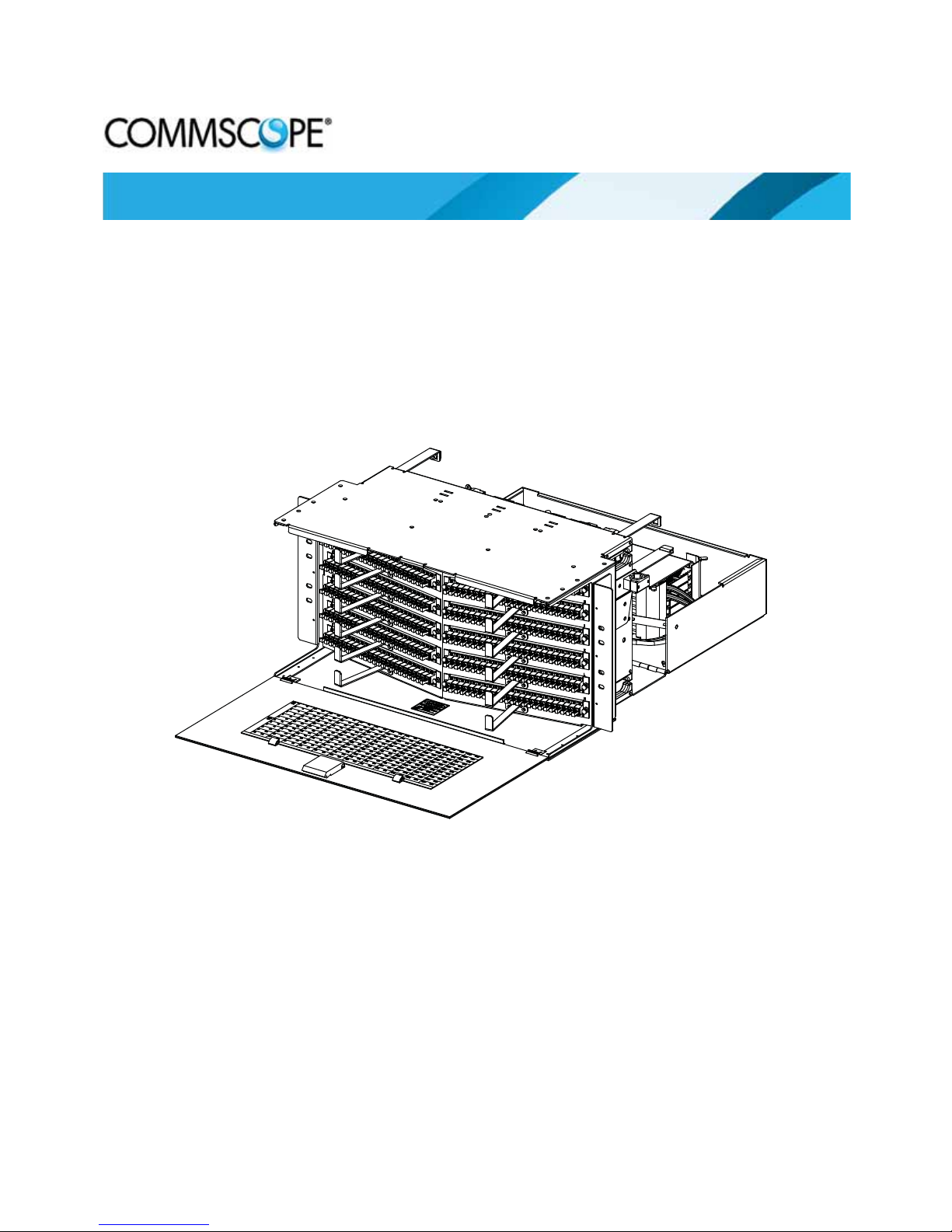
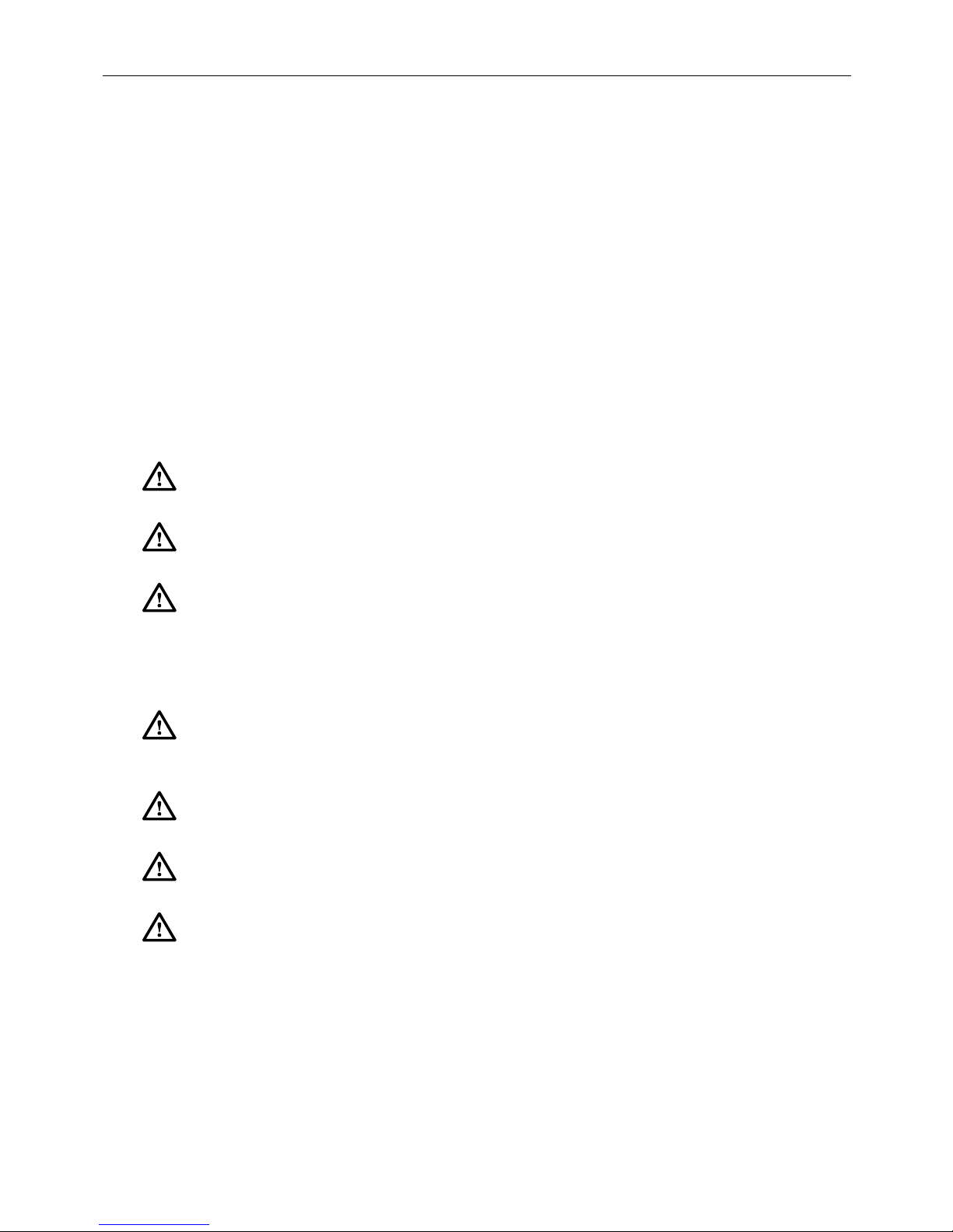
1.1 General Description
The LSX 288-position termination with splicing panel, shown in Figure 1, is a 23-inch rackmount, LGX-compatible panel that provides a splici
optic cables and a termination bulkhead for fiber optic patch cords.
ADCP-93-103 • Issue 3 • November 2016
ng transition between one or more fiber
This panel has a 15-inch depth permitting splice trays to be mounted in its back compartment.
The rear door swings down and locks in an open position to provide a horizontal working
surface for installing splices. The panel is designed to be mounted on an LSX 18-inch deep
high-density frame.
In a typical application, the pa
nel serves as a splicing and di stribution point to transition from
Outside Plant (OSP) or Intra Facility Cable (IFC) to inbuilding circuits connected to with patch
cords. The panel is shipped with pre-terminated, factory-installed pigtails, either of ribbon or
stranded construction. The panel may be used in either an interconnect or cross-connect
configuration, and in either single mode or multimode applications.
The panel is 11 inches (27.9 cm) high. Five panels fit on a standard 7 foot (2.1 m) frame.
Figure 1. LSX 288-Position Termination With Splicing Panel
23202-A
Page 1
© 2017 CommScope. All Rights Reserved.
Page 8
ADCP-93-103 • Issue 3 • November 2016
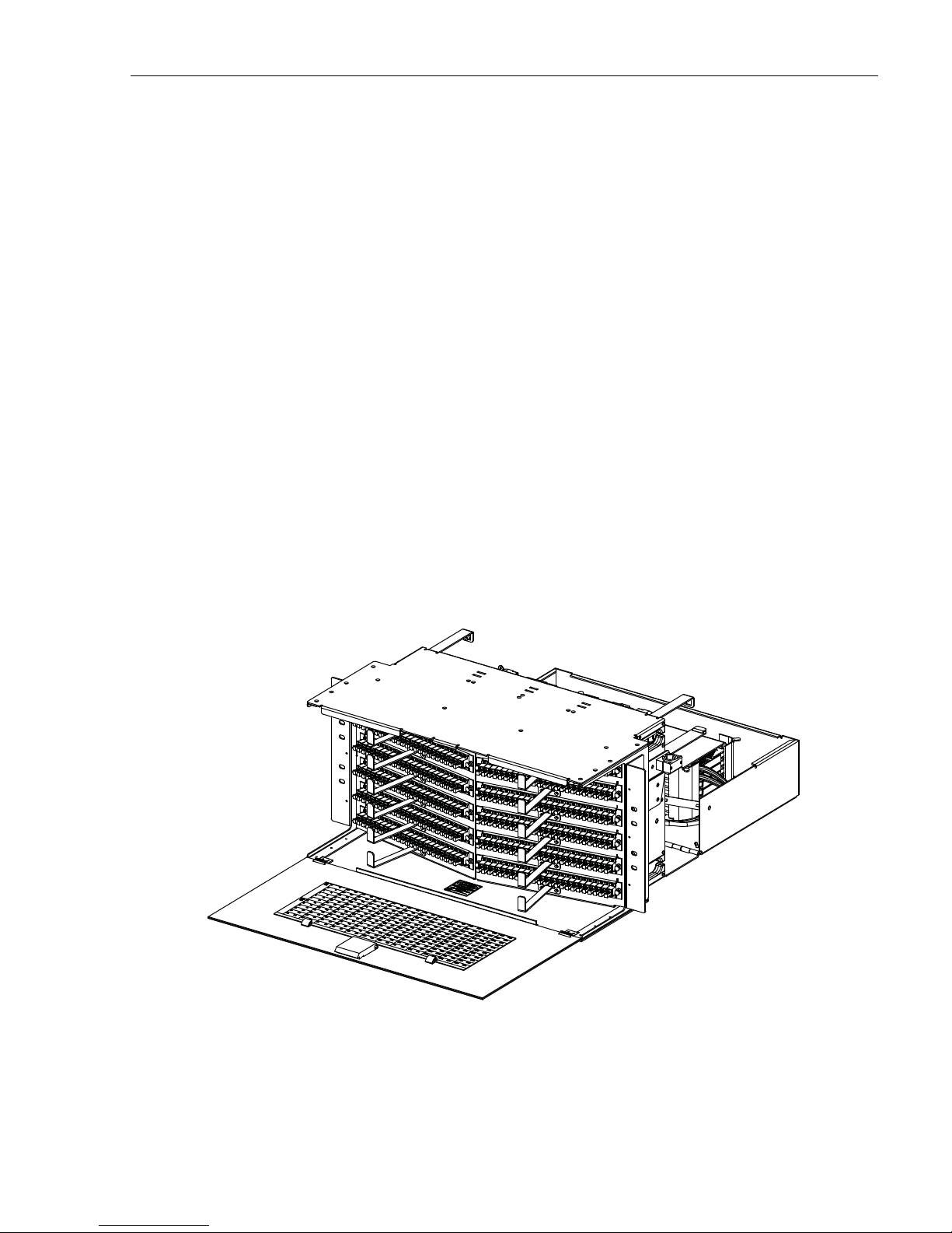
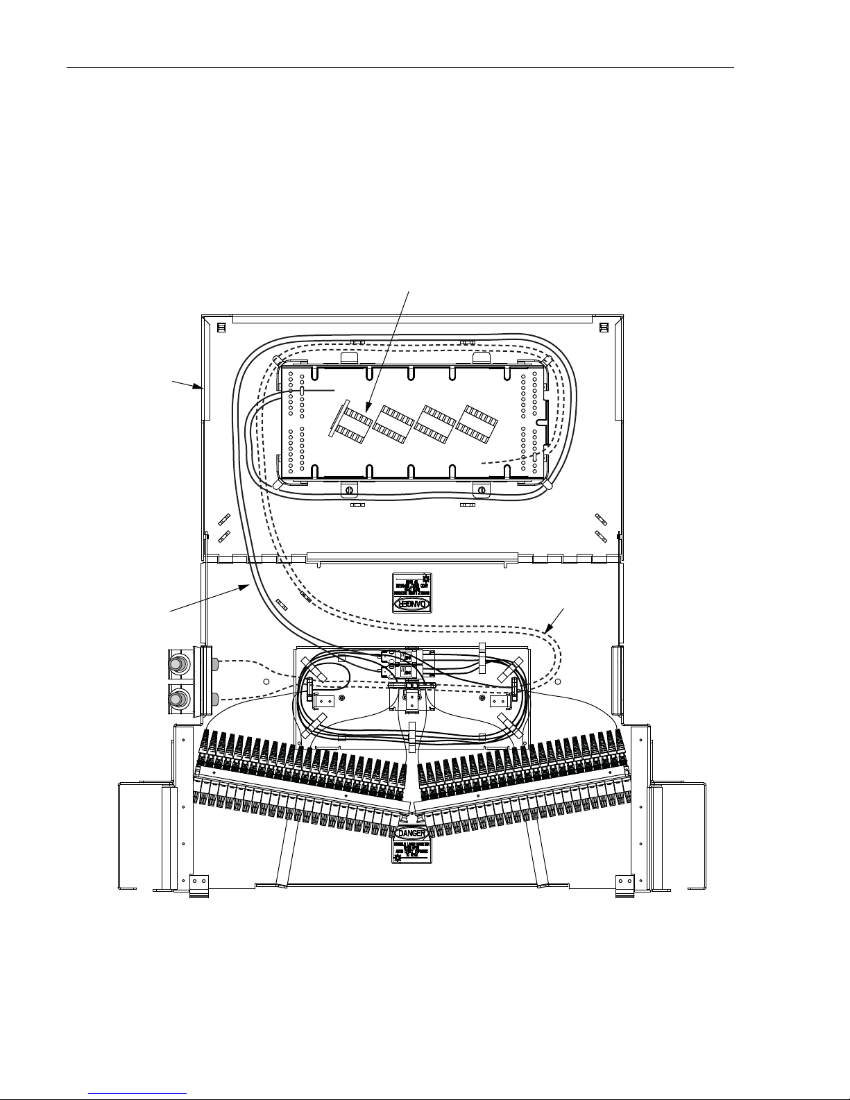
INTERNAL
PIGTAILS
SPLICE TRA Y
ACCESS DOOR
OSP OR IFC
CABLE
23203-A
MASS FUSION
SPLICE CHIP
1.2 Product Function
Figure 2 summarizes the functional components of the LSX panel. As shown, an OSP or IFC
cable is routed through the panel to the splice area
spliced to internal ribbon pigtails. The internal pigtails transition to the bulkhead, located on the
front of the panel. Patch cords installed from the front side of the panel provide the connection
to fiber optic terminal equipment.
access door, where the component fibers are
Figure 2. Functional Components of LSX Termination
With Splicing Panel (Cut-Away Top View)
Page 2
© 2017 CommScope. All Rights Reserved.
Page 9

1.3 Main Components
23205-A
CONNECTOR
PACK
BULKHEAD
CHASSIS
PATCH CORD
GUIDE
REMOVABLE
FRONT COVER
PATCH CORD
DESIGNATION
CARD
MOUNTING
BRACKET
SPLICE TRA Y
ACCESS DOOR
Figure 3 shows the main external features of the LSX 288 Termination With Splicing Panel.
ADCP-93-103 • Issue 3 • November 2016
The features shown are as follows (going from top left counterclockwise in Figure 3):
• Chas
sis—is LGX compatible. It is of solid metal construction and painted white. Five
chassis may be installed on an LGX frame.
• Bulkhead—holds the pass-through adapters that provide the physical interface between
th
e connector ends of the LSX internal pigtails and patch cords installed on the front side
of the bulkhead. Its angled construction facilitates installation of patch cords.
• Con
nector Pack—mounts in the bulkhead providing one row of 24 adapters/connectors
for terminating patch cords. SC or LC connector types are available.
• Remo
vable Front Cover—provides unimpeded access for installation of patch cords.
• Patch Cord Des
• Patch Cord Guides—pro
• Mounting Bracket—is design
• Splic
e Tray Access Door—provides access to rear splice area.
Figure 3. Main External Features (Front View)
ignation Card—is used to record patch cord usage.
vide cable management in routing patch cords.
ed for 23-inch rack mount.
© 2017 CommScope. All Rights Reserved.
Page 3
Page 10

ADCP-93-103 • Issue 3 • November 2016
23207-A
OSP OR IFC
CABLE CLAMP
SPLICE
TRAYS
SPLICE TRA Y
ACCESS DOOR
CABLE RING
(TYPICAL)
RIBBON
FANOUT
BRACKET
Every panel has a rear splice area such as shown in Figure 4.
Figure 4. Main Internal Features (Rear View)
From top left counterclockwise, the main features in the rear splice area are as follows:
ble Ring—routes and secures stranded or ribbon cable on entry into splice area.
• Ca
• Splice Trays—secure and protec
• Splice Tray Access Door—folds down p
• Ribbon Fanou
• OSP or
IFC Cable Clamp—secures the cable to the panel.
t Bracket—holds one stack of four fanout chips.
Each panel is shipped with a cable clamp as well as vertical
t splices.
roviding a horizontal splice deck.
cable guides and cable shields (two
of each, not shown). Accessories available for the panel include patch cords, heatshrink- or
mass-fusion splice chips, and cable clamps (if additional clamps are needed).
Page 4
© 2017 CommScope. All Rights Reserved.
Page 11

1.4 Dimensions
18.60 IN.
(47.2 CM)
21.46 IN.
(54.5 CM)
4.78 IN.
(12.1 CM)
9.99 IN.
(25.4 CM)
10.92 IN.
(27.7 CM)
23209-A
TOP VIEW
FRONT VIEW
Figure 5 shows panel dimensions.
ADCP-93-103 • Issue 3 • November 2016
Figure 5. Panel Dimensions
Page 5
© 2017 CommScope. All Rights Reserved.
Page 12

ADCP-93-103 • Issue 3 • November 2016
1.5 Specifications
Table 1 lists specifications for the LSX combination panel.
ITEM DESCRIPTION
Dimensions (HxWxD) 15 x 23 x 15 in. (27.9 x 58.4 x 38.1cm)
Rack Mount Mounts in 23-inch rack
Weight (unloaded) 10 pounds (4.5 kg)
Terminations 288 terminations
Connector type SC or LC
Pre-installed pigtails Ribbon or straned IFC
Splice tray capacity Six splice trays
Splice chips Mass fusion or heatshrink fusion
Table 1. LSX Combination Termination/Splice panel Specifications
2 UNPACKING THE PRODUCT
Unpack and inspect the LSX combination panel as follows:
1. Inspect the exterior of the shipping contai ner for evidence of roug h handling that may have
d
amaged the contents of the container.
2. If damage is detected or if parts are missing, file a c
then notify ADC Customer Service. Save the damaged carton for inspection by the carrier.
Note: For information on how to contact ADC, if needed, see Section 5 on Page 18.
3. Save the shipping container for use in case the equi
date.
3 INSTALLATION
The main steps in installing an LSX panel are: mounting the panel on the frame, breaking out
the cable to be spliced within the panel, installing the cable on the outside of the panel using the
ADC-provided cable clamp, and routing the cable within the panel from the ca ble clamp to the
splice deck. For instructions, refer to the following subsections.
laim with the commercial carrier and
pment requires shipment at a future
3.1 Mounting the Panel on the Frame
Install the panel from the front side of the rack, using the following procedure. Refer to
Figure 6.
Page 6
© 2017 CommScope. All Rights Reserved.
Page 13

ADCP-93-103 • Issue 3 • November 2016
Note: Because of its extra depth due to its rear splice area, the LSX panel should be
installed on an LGX fiber distribution frame with a depth of at least 15 inches (38.1 cm).
CABLE
SHIELD
RACK FRONT
FLANGE
VERTICAL
CABLE GUIDE
(VCG)
1. Locate the two vertical cable guides (VCGs) and two cable shields among the separately
2. Install the VCGs and cable shields using the three small screws provided to secure them to
3. Determine the mounting location for the panel.
4. Secure the mounting brackets to the rack front flange using eight #12-24 mounting screws.
DESIGNATION
CARD
FRONT
DOOR
EDGE
PROTECTOR
MOUNTING
BRACKET
23210-A
Figure 6. Installing the Panel
packaged shipped items.
Note: The VCGs have a left or right orientation and only fit properly on the correct side of
the panel.
the three small holes in the mounting bracket.
© 2017 CommScope. All Rights Reserved.
Page 7
Page 14

ADCP-93-103 • Issue 3 • November 2016
3.2 Breaking Out a Cable
If preparing a cable for installation, break out and prepare the cable corresponding to Figure 7
for ribbon cable and Figure 8 for stranded cable. Kits are
END OF PROTECTIVE TUBE
available from ADC.
HOSE CLAMP
FLARE TUBE
INSTALL PROTECTIVE
TUBES ON RIBBON
IFC RIBBON CABLE
BREAKOUT LENGTH 94 IN. (238.76 CM)
EXPOSED RIBBON LENGTH
12 IN. (30.48 CM)
Figure 7. Recommended Breakout Dimensions for Ribbon Cable
IFC STRANDED CABLE
SUBUNIT
BREAKOUT LENGTH 94 IN. (238.76 CM)
23259-A
Figure 8. Recommended Breakout Dimensions for Ribbon Cable
Page 8
© 2017 CommScope. All Rights Reserved.
EXPOSED LENGTH
12 IN. (30.48 CM)
23258-A
Page 15

3.3 Installing a Cable Clamp
Every panel is shipped with two cable clamps. The clamps can be used to secure a cable to the
chassis. Route the cable in from above or below the panel and secure the cable in the cable
clamp at the cable breakout point. To install a cable clamp, use the following procedure. Refer
to Figure 9.
Note: Figure 9 shows the cable clamp bracket positioned for cable routing from above the
panel. For cable routing from below the panel, turn the cable clamp bracket upside down
compared to how it is shown in the figure an
figure as “for under floor cable entry.”
ADCP-93-103 • Issue 3 • November 2016
d use the mounting holes designated in the
CABLE
CLAMP
COVER
1. Install the cable clamp bracket on the clamp mou
nt plate using two #12-24 screws. Be sure
to position the cable clamp bracket corresponding to the note above.
STANDOFF
RUBBER
GROMMET
MOUNTING
HOLE (4)
YOKE (2)
STANDOFF (2)
CABLE CLAMP BRACKET
MOUNTING HOLES (2)
FOR OVERHEAD
CABLE ENTRY)
CLAMP
MOUNT
PLATE
STANDOFF
SCREW (2)
12-24X
SCREW (2)
CABLE
ENTRY HOLE
CABLE CLAMP BRACKET
(OVERHEAD CABLE POSITION)
Figure 9. Installing a Cable Clamp
CABLE CLAMP BRACKET
MOUNTING HOLES (2)
FOR UNDER FLOOR
CABLE ENTRY)
23248-A
Page 9
© 2017 CommScope. All Rights Reserved.
Page 16

ADCP-93-103 • Issue 3 • November 2016
CABLE GROMMET
GAP
0 - 0.30 IN.
(0 - 8 MM)
1440-A
2. Place the two standoffs in the standoff mounting holes in the cable clamp bracket.
Note: There are four standoff mounting holes. Either the two left holes or two right holes
can be used together, not the two in the middle. Do not mount two cables side by side.
3. Four rubber yokes and two grommets are provided with the cable clamp kit for securing
the cable to the panel. Select the grommet that, when fitted on the cable, as shown in
Figure 10, provides the gap width shown.
4. Open the splice area access door on the rear of the panel and direct the broken out sectio n
of the cable through the cable entry hole into the rear storage area of the panel. Allow the
cable to remain in that position for later routing within the rear storage area.
5. Working on the outside of the panel, where the ca
clamp components on the standoffs, as shown in Figure 9, with the cable secured within
the rubber grommet. Position the cable so
rubber grommet.
6. Secure the cable clamp components to the stando
Figure 9.
3.4 Cable Routing Within Panel
Use the following procedure to route the cable within the panel.
1. Route the cable from the entry hole horizontally across the top of the p
to the splice tray access door as shown in Figure 11 (top entry) and Figure 12 (bottom
entry). Secure the cable to the top of the p
shown in the figures.
2. Loop the cable clockwise around the spl
Figure 10. Grommet Selection
ble bracket was installed, stack the cable
that the breakout point occurs just beyond the
ffs using standoff screws, as shown in
anel and then down
anel using curleyloks at the tie-down points
ice tray as shown in Figure 13.
3. Tie down the cable at the point where the
protective tube per the breakout dimensions provided in Topic 3.2.
Page 10
© 2017 CommScope. All Rights Reserved.
exposed ribbon cable emerges from the
Page 17

23257-A
TIE-OFF
POINTS
ADCP-93-103 • Issue 3 • November 2016
Figure 11. Cable Entry From Top
TIE-OFF
POINTS
23255-A
Figure 12. Cable Entry From Bottom
Page 11
© 2017 CommScope. All Rights Reserved.
Page 18

ENTRY
HOLE
SPLICE TRA Y
ACCESS DOOR
CABLE
CLAMPS
24729-A
MASS FUSION
SPLICE CHIP
BREAKOUT
POINT
REAR VIEW
OSP OR IFC
CABLE
ADCP-93-103 • Issue 3 • November 2016
4 PATCH CORD ROUTING
4.1 Removing the Front Cover
The front cover of the chassis may be remove d to provide easie r access for installa tion of patc h
cords. To remove the cover, lift it straight out of the hinges. To replace a cover, position the
hinge edge of the cover on the hinges and press inward to push the edge into the hinges.
Page 12
© 2017 CommScope. All Rights Reserved.
Figure 13. Cable Routing
Page 19

4.2 Selecting Patch Cord Length
ADC recommends a maximum of four bays pe r lineup with five pan els per bay fo r a max imu m
of 5,670 terminations per lineup. For patch cord length, refer to Table 2.
ADCP-93-103 • Issue 3 • November 2016
Table 2. Recommended Patch Cord Length
NUMBER OF BAYS
APPROXIMATE
PATCH CORD LENGTH NUMBER OF BAYS
1 5 m (16.4 ft.) 3 6 m (19.7 ft.)
2 6 m (19.7 ft.) 4 7 m (23 ft.)
4.3 Routing Patch Cords on Front of Panel
Danger: Infrared radiation is invisible and can seriously damage the retina of the eye. Do not
look into the ends of any optical fiber. Do not look directly into the optical adapters of the
adapter packs. Exposure to invisible laser radiation may result. An optical power meter should
be used to verify active fibers. A protective cap MUST be immediately placed over any radiating
adapter or optical fiber connector to avoid the potential of dangerous amounts of radiation
exposure. This practice also prevents dirt particles from entering the adapter or connector.
Whenever patch cords are installed, route them down and to the side, as shown in Figure 14.
APPROXIMATE
PATCH CORD LENGTH
RADIUS
LIMITER
PATCH CORD
GUIDE
Figure 14. Correct Routing of Patch Cords
23247-A
CONNECTOR
PACK
Page 13
© 2017 CommScope. All Rights Reserved.
Page 20

ADCP-93-103 • Issue 3 • November 2016
VERTICAL
TROUGH
UPPER
RACEWAY
VERTICAL
TROUGH
23244-A
CONNECTING PORTS
ON THE SAME SIDE
OF A SINGLE BAY
VERTICAL
TROUGH
UPPER
RACEWAY
VERTICAL
TROUGH
23236-A
OPTIONAL
PROCEDURE
FOR PANELS
IN UPPER
HALF OF BAY
SINGLE BAY,
OPPOSITE SIDES
OF SAME BAY
4.4 Cross-Connecting Within a Stand-Alone Bay
Cross-connecting within a stand-alone bay may be required when facility and equipment
terminations are intermixed. Most cross-connection routing within a stand-alone bay should be
done with 5 meter (16.5 ft.) patch cords. Shorter 3 meter (9.9 ft.) patch cords can be used when
both ends are terminated in the top half of the bay.
Use the following procedure to route patch cords on a stand-alone bay.
1. Determine whether the ports to be connected are on the same side or opposite sides of the
ba
y, as shown in Figure 15.
2. Select from the routing paths shown a
nd route and connect the patch cord.
3. Loop up any cable slack around the appropriate spool on the vertical trough.
Figure 15. Routing Patch Cords on a Stand-Alone Bay
Page 14
© 2017 CommScope. All Rights Reserved.
Page 21

4.5 Cross-Connecting Between Two or More Bays
VERTICAL
TROUGH
UPPER
RACEWAY
VERTICAL
TROUGH
UPPER
RACEWAY
VERTICAL
TROUGH
23237-A
SAME BAY WITHIN A MULTIBAY LINE-UP
Most cross-connection routing between adjacent racks should be done with 6 meter (19.8 ft.)
patch cords. Shorter 4 meter (13.2 ft.) patch cords can be used when both ends are terminated in
the top left of the frame. To route patch cords between adjacent bays, use the following
procedure.
1. Terminate one end of the patch cord on the originating LSX panel and bay, then route the
cord left or right to the nearest vertical trough.
patch
ADCP-93-103 • Issue 3 • November 2016
2. At the destination panel and bay,
terminate the opposite end of the patch cord, then route
the patch cord left or right to the nearest vertical trough.
3. Allow the patch cord to droop down
4. Based on the termination and ending points for the
into the lower raceway.
patch cord, select from the routing
paths shown in Figure 16 on this page or Figure 17 on the next page.
5. Arrange the patch cord using the lower ra
ceway and the indicated vertical trough to take
up the cable slack around the appropriate spool in the vertical trough.
Figure 16. Routing Patch Cords Between Adjacent Bays
Page 15
© 2017 CommScope. All Rights Reserved.
Page 22

23238-A
23242-A
23243-A
VERTICAL
TROUGH
UPPER
RACEWAY
VERTICAL
TROUGH
UPPER
RACEWAY
VERTICAL
TROUGH
ADCP-93-103 • Issue 3 • November 2016
Figure 17. Alternate Paths for Patch Cords Between Adjacent Bays
Page 16
© 2017 CommScope. All Rights Reserved.
Page 23

4.6 Interconnect Procedures
In an interconnect configuration, route the patch cord from the Fiber Optical Terminal (FOT)
equipment through an overhead or underfloor raceway as shown in Figure 18. Take up slack
using the vertical trough as sh
TO FOT
EQUIPMENT
OVERHEAD CABLING
ADCP-93-103 • Issue 3 • November 2016
own in the figure.
OVER RAISED
FLOOR CABLING
TO FOT
EQUIPMENT
Figure 18. Routing Patch Cords Between Adjacent Bays
© 2017 CommScope. All Rights Reserved.
23245-A
Page 17
Page 24

ADCP-93-103 • Issue 3 • November 2016
5 CUSTOMER INFORMATION AND ASSISTANCE
http://www.commscope.com/SupportCenter
Page 18
 Loading...