


ATC200-LITE-USB
Teletilt® Remote Control
Variable Electrical Downtilt System
Installation and Operation User Guide
|
Bulletin 639536 • Revision L • October 2014 |
CommScope |
Customer Service 24 hours |
1100 CommScope Place SE P.O. Box 339, Hickory, NC 28603-0339 |
North America: +1-800-255-1479, Option 1 (toll free) |
(828) 324-2200 (800) 982-1708 |
Any country: +1-779-435-6500, Option 1 |
www.commscope.com/andrew |
email: acicustomersupportcenter@commscope.com |
Notice: CommScope disclaims any liability or responsibility for the results of improper or unsafe installation, inspection, maintenance, or removal practices.
Aviso: CommScope no acepta ninguna obligación ni responsabilidad como resultado de prácticas incorrectas o peligrosas de instalación, inspección, mantenimiento o retiro. Avis : CommScope décline toute responsabilité pour les conséquences de procédures d’installation, d’inspection, d’entretien ou de retrait incorrectes ou dangereuses. Hinweis: CommScope lehnt jede Haftung oder Verantwortung für Schäden ab, die aufgrund unsachgemäßer Installation, Überprüfung, Wartung oder Demontage auftreten.
Atenção: A CommScope abdica do direito de toda responsabilidade pelos resultados de práticas inadequadas e sem segurança de instalação, inspeção, manutenção ou remoção. Avvertenza: CommScope declina eventuali responsabilità derivanti dell’esecuzione di procedure di installazione, ispezione, manutenzione e smontaggio improprie o poco sicure.
© 2014 CommScope Bulletin 639536

ATC200-LITE-USB Teletilt® RET System
Revision History
Revision No. |
Date |
Description of Changes |
|
|
|
A |
October 2006 |
Released. |
|
|
|
B |
January 2007 |
Change discussion on device configuration settings in |
|
|
Section 4 to show that factory installed actuators are |
|
|
pre-configured to include the antenna model number, |
|
|
antenna type, and antenna serial number. |
|
|
|
C |
September 2007 |
No longer uses lite scan. |
|
|
Calibrate button added for other antenna vendor actua- |
|
|
tor calibrations. |
|
|
Added operating instructions for use with SmartBeam™ |
|
|
antennas. |
|
|
|
D |
May 2008 |
ATC Lite v5.0 supports both AISG 1.1 and 2.0 proto- |
|
|
cols. |
|
|
Main screen displays AISG mode. |
|
|
Added section on switching AISG mode in Andrew ac- |
|
|
tuators. Added warranty notice. |
ENovember 2008 Updated from Version 5.0 to 6.0.
|
|
Added 3 sections about configuring and adjusting |
|
|
Multiple Integrated Actuators. |
|
|
|
F |
April 2009 |
Contact information updated |
|
|
|
G |
August 2012 |
Updated for the features implemented in ATCLIte 7.2 |
|
|
as per the EAO 600300. |
HNovember 2012 Contact information updated
J |
March 2013 |
Update the ATCLite7.2 software features |
|
|
|
K |
November 2013 |
Updated for the features implemented in ATCLite 8.0 |
|
|
with support for full control of TMAs. |
|
|
|
L |
October 2014 |
Updated the latest CommScope branding to document. |
Bulletin 639536 • Revision L |
October 2014 |
i |

ATC200-LITE-USB Teletilt® RET System
Notices and Precautions
IMPORTANT
Before installing/operating the ATC200-LITE- USB controller, please DOWNLOAD the latest antenna definition file and controller software from the Commscope web site at www.commscope.com. Please register online to receive E-mail notifications for software updates.
WARRANTY NOTICE
Proper installation procedures must be followed when installing and operating RET equipment. Failure to assure installations are done properly by trained installation personnel and to follow procedures discussed in this bulletin may cause warranty for such products to be void.
Andrew requires that all RET installations be pre-tested and configured prior to installation. Failure to conduct pretest and pre-installation procedures defined by Andrew will void warranty.
SAFETY NOTICE
The installation, maintenance, or removal of an antenna requires qualified, experienced personnel. Andrew installation instructions are written for such installation personnel. Antenna systems should be inspected once a year by qualified personnel to verify proper installation, maintenance, and condition of equipment.
Andrew disclaims any liability or responsibility for the results of improper or unsafe installation practices.
|
|
|
|
|
|
|
|
|
|
|
Do not install near power lines. |
Do not install on a wet or |
Wear shoes with rubber soles |
||||||||
Power lines, telephone lines, |
windy day or when |
and heels. Wear protective |
||||||||
and guy wires look the same. |
lightning or thunder is |
clothing including a |
||||||||
Assume any wire or line can |
in the area. Do not use |
long-sleeved shirt and rubber |
||||||||
electrocute you. |
metal ladder. |
gloves. |
||||||||
|
|
|
|
|
|
|
|
|
||
|
Installation Training Available at Andrew Institute |
|||||||||
|
|
|
|
|
|
|
|
|
|
|
ii |
October 2014 |
|
|
|
Bulletin 639536 • Revision L |
|||||
ATC200-LITE-USB Teletilt® RET System
WARNING
It is very important to disconnect the ATC200-LITE-USB controller from the system after each use to prevent permanent damage to the system.
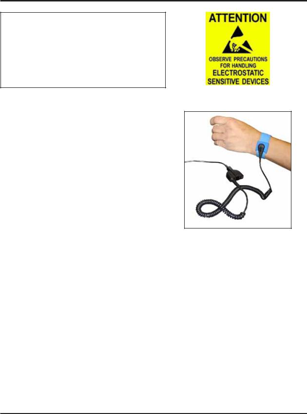
Electric Static Discharge (ESD) can damage or destroy the hardware equipment used for the ATC200- LITE-USB Teletilt® System. ESD can occur during handling of equipment without the user feeling a shock. The following precautions should be taken to prevent ESD.
1.Wear an ESD wrist strap (Figure 1) and/or use a test lead (ground), such as a single-wire conductor with a series resistance of 1 megohm equipped with alligator clips on each end. In using a ground, one end of the alligator clip is connected to a grounded equipment frame and the other end of the alligator clip is touched with a bare hand.
2.Other precautions the user may take to reduce the risk of ESD are:
Figure 1. ESD Wrist Strap.
•avoid wearing clothing that conducts static electricity, such as wool
•remove all jewelry
•avoid handling equipment during an electrical storm
3.Before opening a package containing an electrostatic unit or an electrostatic sensitive device/ assembly, clip the free end of a test lead to the package. Leave the other end connected to the equipment frame or other ESD ground. This will cause any static electricity which may have built up on the package to discharge. Keep the unit package grounded during removal or placement of equipment in the package.
4.Minimize handling of ESDS (Electric Static Discharge Sensitive) equipment. Keep replacement equipment in the electrostatic-free packaging (with ground established between packaging and equipment frame) until needed. Repairable ESD equipment should be placed in the electrostaticfree packaging (with ground connecting package to equipment frame) upon removal from ATC200- LITE-USB system. ESD equipment should only be transported and stored in ESD protective packaging.
5.Always avoid unnecessary movement of body, such as scuffing feet across flooring, when handling ESDS equipment. Such movement will generate additional charges of static electricity.
Bulletin 639536 • Revision L |
October 2014 |
iii |

ATC200-LITE-USB Teletilt® RET System
6.When removing or replacing ESDS equipment, hold the device or assembly through the electro- static-free wrap, where possible. If this is not possible, lift the device or assembly by its body only. Do not touch component leads, connector pins, or any other electrical connections or paths, even though they are covered by conformal coating.
7.Do not allow ESDS equipment to come in contact with clothing or other ungrounded materials that may have an electrostatic charge. Charges on non-conductive material are not equal. For instance, a plastic storage bag may have a –10,000 volt potential 1/2 inch from a +15,000 volt potential with many such charges all over the bag. Do not hand ESD equipment to another person until it is safely packaged for protection for ESD.
8.When moving ESDS equipment, always touch the surface on which it rests with bare skin for at least one second before lifting. Before setting it on any surface, touch the surface with your free hand for at least one second. Contact with bare skin provides a safe discharge path for charges accumulated while you are moving around.
9.While servicing equipment containing ESD devices, do not handle or touch materials such as plastic, vinyl, synthetic textiles, polished wood, fiberglass, or similar items that can generate static charges; unless you repeat the grounding process with bare hands after contacting these materials.
10.Where possible, avoid repairs that require soldering at the equipment level. Soldering irons must have heater/tips assemblies that are grounded to an electrical ground. Do not use standard plastic solder suckers (special antistatic solder suckers are commercially available).
11.Ground the leads of test equipment momentarily before you energize the test equipment and before you probe ESD devices or assemblies.
12.Work benches used for setting ESDS equipment should have ESD protective work surfaces. These work benches should also have personnel ground straps. These straps prevent discharge of static electricity from personnel handling ESDS items on the work bench surface. The work bench surface should be connected to a ground through a ground cable. The resistance in the bench top ground cable should be located at or near the point of contact with the top of the work bench. The resistance should be high enough to limit any leakage current to 5 milliamperes or less. This takes into consideration the highest voltage source within reach of grounded people and all the parallel resistances to ground, such as wrist ground straps, table tops, and conductive flooring.
iv |
October 2014 |
Bulletin 639536 • Revision L |

Table of Contents
Revision History .................................................................................................... |
i |
|
Notices and Precautions........................................................................................ |
ii |
|
|
|
|
|
Part 1 – Initial Setup |
|
|
|
|
Section 1 Program Installation .......................................................................... |
1-1 |
|
1.0 |
System Requirements/Recommendations................................................................. |
1-1 |
1.1 |
Program Download and Installation ........................................................................... |
1-1 |
Section 2 Controller Setup................................................................................ |
2-1 |
|
2.1 |
System Description .................................................................................................... |
2-1 |
2.2 |
Controller Communication.......................................................................................... |
2-2 |
2.3 |
Controller Setup ......................................................................................................... |
2-3 |
2.4 |
Program Startup......................................................................................................... |
2-7 |
|
|
|
|
Part 2 – Uploading Firmware |
|
|
|
|
Section 3 Uploading Firmware .......................................................................... |
3-1 |
|
3.0 |
Overview .................................................................................................................... |
3-1 |
3.1 |
Installing Firmware Updates to Actuators................................................................... |
3-1 |
3.2 |
Installing Firmware Updates to TMA devices ............................................................. |
3-2 |
3.3 |
Updating the Antenna Definition File.......................................................................... |
3-5 |
3.4 |
Specifying an Antenna Definition File......................................................................... |
3-5 |
|
|
|
|
Part 3 – Device Discovery for All Types of Antennas |
|
|
|
|
Section 4 Device Discovery and Addressing...................................................... |
4-1 |
|
4.1 |
Device Search.......................................................................................................... |
4-1 |
4.2 |
Device Information Views......................................................................................... |
4-5 |
4.2.1 |
All Devices View ....................................................................................................... |
4-5 |
4.2.2 |
RET Devices View.................................................................................................... |
4-6 |
4.2.3 TMA Devices View.................................................................................................... |
4-7 |
|
4.3 |
Addressing................................................................................................................ |
4-8 |
Bulletin 639536 • Revision L |
October 2014 |
v |

Table of Contents |
ATC200-LITE-USB Teletilt® RET System |
|||
|
|
|
|
|
|
|
Part 4 – Operating Instructions for Standard Antennas |
|
|
|
|
with Attached Actuators |
|
|
|
|
|
|
|
Section 5 |
Actuator Protocol Mode Switching.................................................... |
|
5-1 |
|
5.0 Protocol Mode switching for ATM3 devices.............................................................. |
|
5-1 |
||
5.0.1 Using AISG Reset Option Tools ............................................................................... |
|
5-1 |
||
5.0.2 Switching a Single ATM200-002 to Ericsson Protocol.............................................. |
|
5-4 |
||
5.1 Protocol Mode switching for AccuRET devices ........................................................ |
|
5-6 |
||
Section 6 |
Device Configuration ........................................................................ |
|
6-1 |
|
Section 7 |
Changing the Electrical Downtilt on a Single Antenna...................... |
7-1 |
||
Section 8 |
Changing the Electrical Downtilt on a Group of Antennas................ |
8-1 |
||
|
|
|||
Part 5 – Operating Instructions for Antennas with Multiple |
|
|||
|
|
Integrated Actuators |
|
|
|
|
|||
Section 9 Switching Operating Modes for Multiple Integrated Actuators ........ |
9-1 |
|||
Section 10 Device Configuration for Antennas with Multiple Integrated |
|
|||
|
|
Actuators..................................................................................... |
|
10-1 |
Section 11 |
Adjusting the Electrical Downtilt on a Single Antenna Equipped |
|
||
|
|
with Multiple Integrated Actuators............................................... |
|
11-1 |
Section 12 |
Adjusting the Electrical Downtilt on a Group of Antennas Equipped |
|||
|
|
with Multiple Integrated Actuators............................................... |
|
12-1 |
|
|
|||
Part 6 – Operating Instructions for SmartBeamTM Antennas |
|
|||
Section 13 Device Configuration with SmartBeam™ Antennas ...................... |
13-1 |
|||
Section 14 Changing the Electrical Downtilt on a Single SmartBeam™ |
|
|||
|
|
Antenna ........................................................................................ |
|
14-1 |
Section 15 Changing the Boresight (Pan) on a Single SmartBeam™ |
|
|||
|
|
Antenna ........................................................................................ |
|
15-1 |
Section 16 Changing the Beamwidth (Fan) on a Single SmartBeamTM .................. |
|
|||
|
|
Antenna ........................................................................................ |
|
16-1 |
Section 17 Changing the Electrical Downtilt on a Group of SmartBeam™ |
|
|||
|
|
Antennas....................................................................................... |
|
17-1 |
|
|
|
|
|
iivi |
October 2014 |
Bulletin 639536 • Revision L |
||
|
|
|
|
|

ATC200-LITE-USB Teletilt® RET System |
Table of Contents |
|
|
|
|
|
Part 7 – Saving Reports and Retrieving Alarm Status |
|
|
|
|
Section 18 Saving a Site Report or Site Configurations................................... |
18-1 |
|
18.1 |
Saving/Viewing a Site Report Formatted to Open in Word ..................................... |
18-1 |
18.2 |
Saving/Viewing a Site Report Formatted to Open in Excel ..................................... |
18-4 |
Section 19 Device Test, Alarm Status, and Device Information ...................... |
19-1 |
|
19.1 |
Obtaining Device Information.................................................................................. |
19-2 |
19.2 |
Retrieving Current Alarm Status.............................................................................. |
19-2 |
19.3 |
Clearing All Alarms on a Device .............................................................................. |
19-3 |
19.4 |
Executing a Self Test Movement for a Device......................................................... |
19-3 |
Section 20 Alarm Status for TMA .................................................................. |
20-1 |
|
20.1 |
Alarm Reported by TMA .......................................................................................... |
20-1 |
20.2 |
Retrieving Current Alarm from TMA ........................................................................ |
20-3 |
20.3 |
Clearing All Alarms on TMA..................................................................................... |
20-4 |
Part 8 – Operating Instructions for Tower Mounted Amplifiers (TMA)
Section 21 |
Device Configuration with TMA................................................... |
21-1 |
Section 22 |
Changing the Gain on a Variable-Gain TMA ................................ |
22-1 |
Section 23 |
Changing the Operating Mode on a TMA ..................................... |
23-1 |
Part 9 – Appendix
Appendix A Letter of Compliance.................................................................... |
A-1 |
Appendix B Declaration of Conformity............................................................ |
B-1 |
Site Configuration Worksheet ........................................................ |
(Tear Out Page) |
Bulletin 639536 • Revision L |
October 2014 |
vii |

Table of Contents |
ATC200-LITE-USB Teletilt® RET System |
This page intentionally left blank.
viii |
October 2014 |
Bulletin 639536 • Revision L |
Part 1
Initial Setup
Bulletin 639536 • Revision L |
October 2014 |

Part 1–Initial Setup |
ATC200-LITE-USB Teletilt® RET System |
This page intentionally left blank.
October 2014 |
Bulletin 639536 • Revision L |
Section 1
Program Installation
The controller MUST remain disconnected from the computer and its power supply during the ATC Lite software installation process.
1.0 System Requirements/Recommendations
Required: |
• Windows® 2000 or XP operating systems, or newer |
|
• Available working USB port (USB1.1 or USB2.0) |
Recommended: |
• Screen resolution of 1024 x 768, or higher |
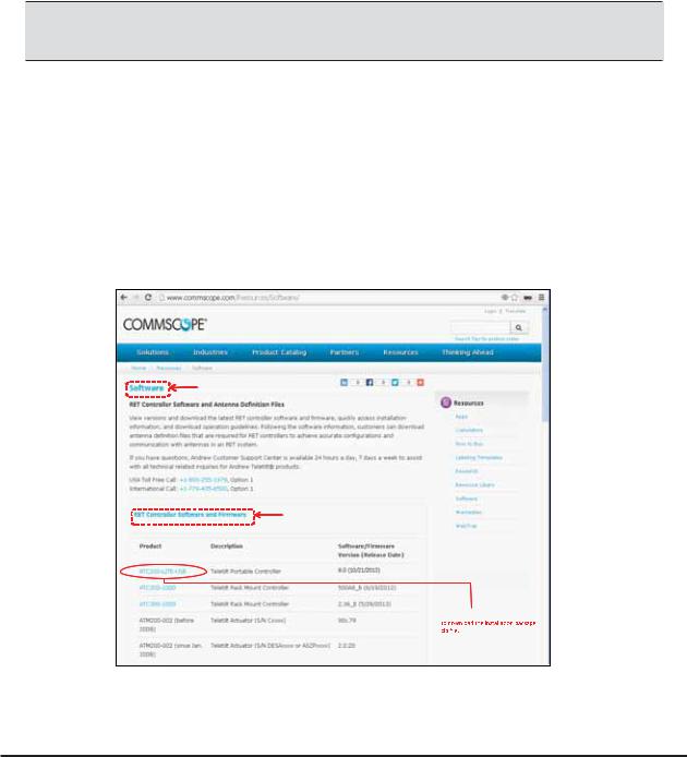
1.1 Program Download and Installation
If you are upgrading the ATC Lite software from an earlier installed version, it is recommended that the earlier version is uninstalled before the new version is installed. Download the ATC Lite software zip file.
From www.commscope.com click on Resources Resourc e Library, then click on ‘


 ’ link on the right side pane ‘Resources’ to view this page.
Click on this link ‘


 Firmware’ to view the list of downloads as shown here.
Click on this link ‘ATC200-LITE-USB’
Figure 1-1. Downloading ATC Lite Software.
Microsoft, Encarta, MSN, and Windows are either registered trademarks or trademarks of Microsoft Corporation in the United States and/or other countries.
Bulletin 639536 • Revision L |
October 2014 |
1-1 |
Section 1–Program Installation |
ATC200-LITE-USB Teletilt® RET System |
1.Download the ATC Lite software zip file. From the www.commscope.com click on the Resources drop down and then on RESOURCE LIBRARY link, then select the link Software on the right side pane named Resources. In the Software page click on the link RET Controller Software and Firmware to view the download list.
Select the ATC200-LITE-USB link to download the installation zip file (See Figure 1-1).
2.This zip file can be placed in any directory on the PC’s local C:\ drive. Double-click on the zip file to extract the ATC Lite setup file and its supporting installation documentation.
Do not connect the ATC200-LITE-USB controller to the computer at anytime during the software installation process.
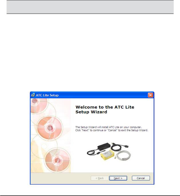
3.Double click on the setup file (eg. ATCLite80Setup.msi) to begin the installation process. Note that the number shown in the filename represents the software release version.
During the program installation process, a single antenna definition file and additional support files will self-extract into the same directory with the program file, and a program icon will be placed on the computer’s desktop. The antenna definition file provides the program with an updated drop down list of antennas compatible with the ATC200-LITE-USB controller. Tilt parameters for each antenna are included in the antenna definition file to show the tilt range for each antenna and to communicate instructions to the antenna/actuator when tilt adjustments are made from the controller. Latest firmware files for Tower Mounted Amplifiers (TMA) and USB driver files are available
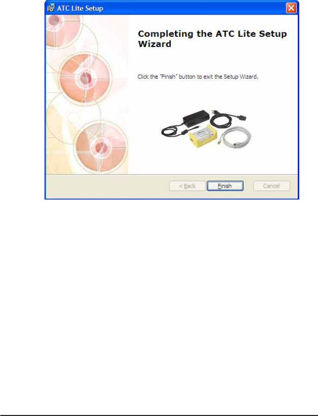
4.Follow the on-screen prompts, as shown in Figures 1-2 through 1-5.
5.This installation process automatically installs the relevant USB drivers (32 bit or 64 bit) for con necting the ATC200-Lite-USB device through USB connection. Proceed to Section 2.3, Control ler setup for further instructions for connecting using serial or USB.
Figure 1-2. ATC Lite Software Setup Wizard.
1-2 |
October 2014 |
Bulletin 639536 • Revision L |
ATC200-LITE-USB Teletilt® RET System |
Section 1–Program Installation |
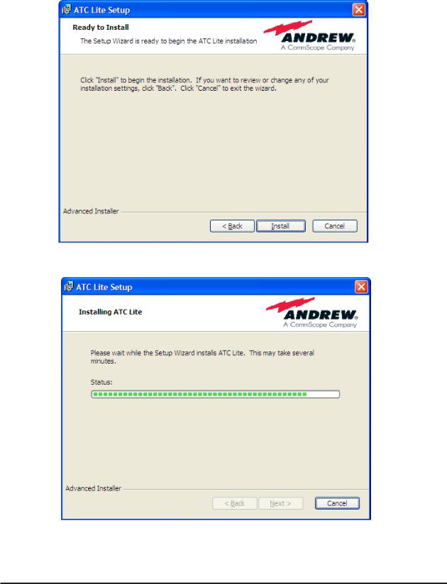
Figure 1-3. ATC Lite Software setup.
Figure 1-4. Status for ATC Lite Software Installation.
Bulletin 639536 • Revision L October 2014 1-3
Section 1–Program Installation |
ATC200-LITE-USB Teletilt® RET System |
Figure 1-5. Completing ATC Lite Software Installation.
1-4 |
October 2014 |
Bulletin 639536 • Revision L |

ATC200-LITE-USB Teletilt® RET System |
Section 1–Program Installation |
This page intentionally left blank.
Bulletin 639536 • Revision L |
October 2014 |
1-5 |
Section 2
Controller Setup
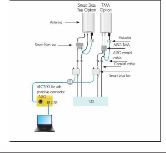
2.1 System Description
The ATC200-LITE-USB is an antenna system controller that is used within the Andrew Teletilt® RET system to manage electrical tilt settings of an antenna(s) remotely. Figure 2-1 shows an example of components used in an ATC200-LITE-USB Teletilt system. Follow the procedures described in the installation bulletins included with each component for successful installation for each device.
Figure 2-1. Example of Andrew Teletilt® Basic RET System with an ATC200-LITE-USB.
2-1 |
October 2014 |
Bulletin 639536 • Revision L |
ATC200-LITE-USB Teletilt® RET System |
Section 2–Controller Setup |
It is recommended that each actuator be connected to the controller while on the ground and tested for proper function. The following site antenna/actuator information should be recorded before the antennas are installed on the tower:
•The serial number for each actuator
•The antenna type (model number) in which the actuator will be operating
•The location the antenna will be positioned at on the tower site
This will assist in configuring the controller to manage tilt operations successfully for each actuator. A site configuration worksheet is provided at the end of this manual to record the antenna/actuator information.
2.2 Controller Communication
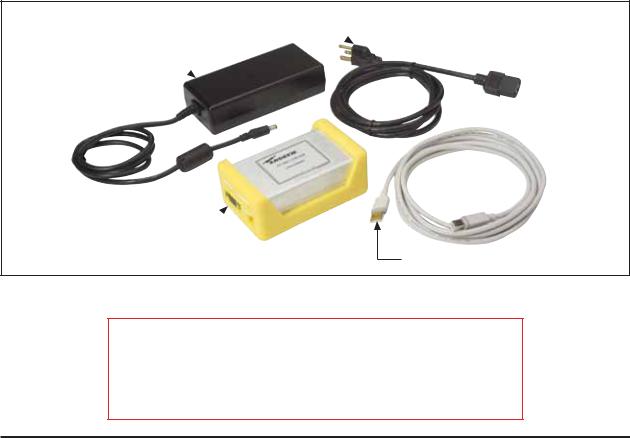
The controller serves as an interface between a local PC/laptop and the ATM200 RET actuator/ antenna system. The ATC200-LITE-USB controller provides signal level conversion from a PC to RS–485 (used in the ATM200 actuators), as well as power to the ATM200 actuators that are attached to the antennas. LEDs on the controller are used to indicate power and data communication. The ATC200-LITE-USB controller is equipped with a USB port, as well as a RS–232 serial port for flexibility in connecting to a PC. See Figures 2-2 and 2-3.
Note that although data is stored in the actuator, it can not be saved in the controller. All site information can be saved on the PC (see Section 13).
Power Cord
dc Power Converter
ATC200-LITE-USB
Controller
USB Cable
Figure 2-2. ATC200-LITE-USB Controller Kit.
IMPORTANT
DISCONNECT THE ATC200-LITE-USB CONTROLLER FROM THE
RET SYSTEM AT THE END OF EACH SESSION TO PREVENT
POSSIBLE DAMAGE TO RET DEVICES.
Bulletin 639536 • Revision L |
October 2014 |
2-2 |
Section 2–Controller Setup |
ATC200-LITE-USB Teletilt® RET System |
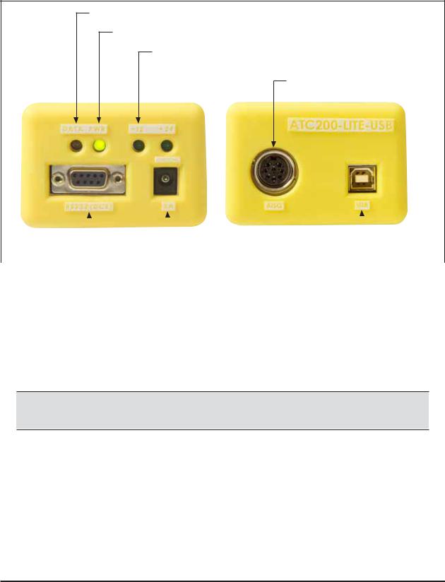
Data LED flashes green on transmitting and red on receiving signals.
Power LED is green when power is input.
+12 and +24 LEDs are lit to show voltage level output.
AISG female port for control cable from antenna.
RS-232 |
|
dc IN Port |
|
|
|
USB Port |
|
|
|
|
|||
Serial Port |
|
|
|
|||
|
|
|
|
|||
|
|
|
|
|
|
|
|
|
Figure 2-3. ATC200-LITE-USB Controller End Panels. |
||||
2.3 Controller Setup
Connect the supplied 24 Vdc power converter to the dc IN port on the controller (Figure 2-3).
Verify that the PWR LED turns green.
1. Using a USB Connection
•Connect the supplied USB cable between the controller and the PC. See Figure 2-3 for port connections on the controller.
The first time you connect a given ATC200-LITE-USB controller to a given local computer, the drivers will be loaded automatically for the USB connection.
•If you are prompted to locate/install the USB driver for the new device found, then the drivers failed to install during the installation process.
Proceed as given below.
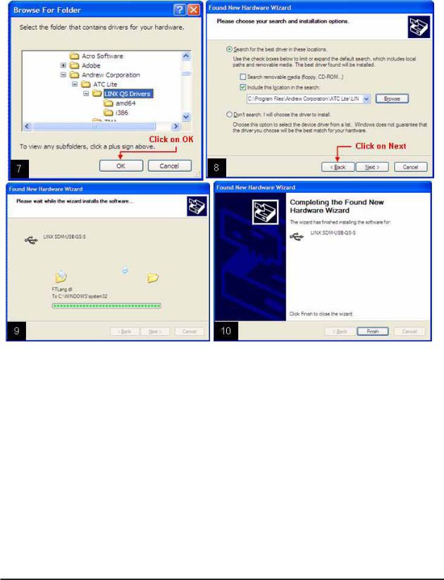
•Follow the steps shown in Figures 2-4 through 2-6 to successfully install the USB driver for the ATC200-LITE-USB controller.
•See paragraph 2.4 to launch the ATC Lite program and view the USB port assignment.
Microsoft, Encarta, MSN, and Windows are either registered trademarks or trademarks of Microsoft Corporation in the United States and/or other countries.
2-3 |
October 2014 |
Bulletin 639536 • Revision L |
ATC200-LITE-USB Teletilt® RET System |
Section 2–Controller Setup |
 1. Select No, not this time.
2. Click on Next.
Figure 2-4. Notification When New Hardware Is Found.
Bulletin 639536 • Revision L |
October 2014 |
2-4 |

Section 2–Controller Setup |
ATC200-LITE-USB Teletilt® RET System |
Figure 2-5. Locating the ATC Lite Directory.
2-5 |
October 2014 |
Bulletin 639536 • Revision L |
ATC200-LITE-USB Teletilt® RET System |
Section 2–Controller Setup |
Figure 2-6. Installing USB Driver.
Bulletin 639536 • Revision L |
October 2014 |
2-6 |
Section 2–Controller Setup |
ATC200-LITE-USB Teletilt® RET System |
2.4 Program Startup
1.Connect the desired length RET control cable between the controller’s AISG connector and the first device in the RET system (or actuator that is to be tested before the antenna is mounted on the tower).
2.Double-click on the ATC Lite icon that was placed on
the computer’s desktop during program installation |
Figure 2-8. ATC Lite Program Icon. |
(Figure 2-8). |
|
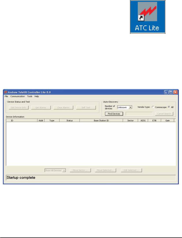
3.The controller program will open to its main screen (Figure 2-9).
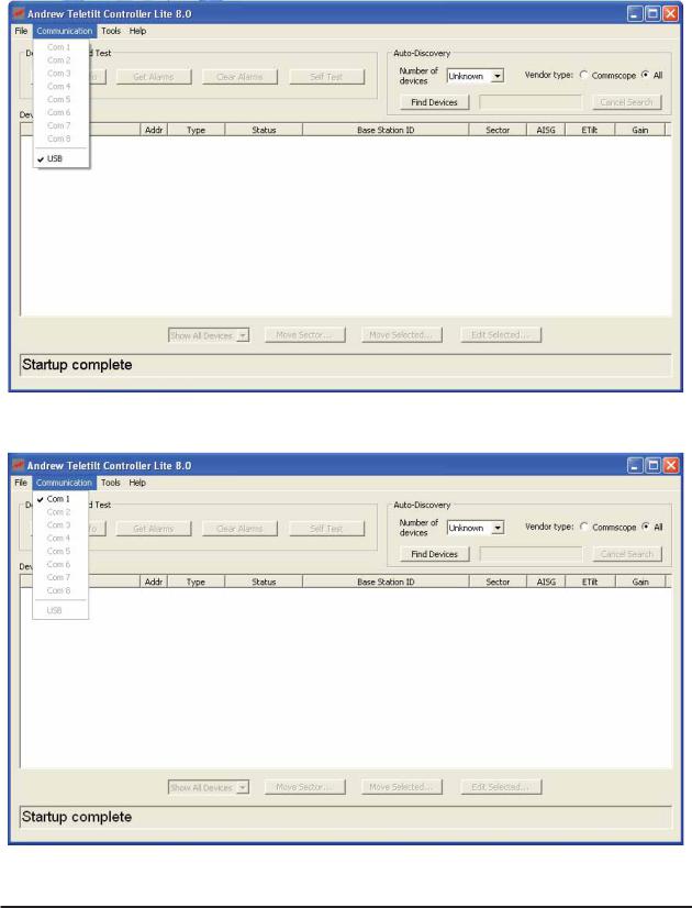
4.Select Communication from the main menu to view the communication port used for the connection. See Figures 2-10 and 2-11 for examples.
5.If you desire to exit the program at this time, select File→Exit from the main menu or click on the X in the far top right.
Figure 2-9. ATC Lite Program Main Screen.
2-7 |
October 2014 |
Bulletin 639536 • Revision L |
ATC200-LITE-USB Teletilt® RET System |
Section 2–Controller Setup |
Figure 2-10. USB Port Connection Shown.
Figure 2-11. COM Port (Serial) Connection Shown.
Bulletin 639536 • Revision L October 2014 2-8

Section 2–Controller Setup |
ATC200-LITE-USB Teletilt® RET System |
This page intentionally left blank.
2-9 |
October 2014 |
Bulletin 639536 • Revision L |

Part 2
Uploading Firmware
Bulletin 639536 • Revision L |
October 2014 |

Part 2–Uploading Firmware |
ATC200-LITE-USB Teletilt® RET System |
This page intentionally left blank.
October 2014 |
Bulletin 639536 • Revision L |
Section 3
Uploading Firmware
3.0 Overview
Firmware files for the Andrew Teletilt controller and antenna definition file can be downloaded from Software web page on the web site www.commscope.com, by Clicking on the Resources →RESOURCE LIBRARY link, then select the link Software on the right side pane named Resources. In the Software page click on the link RET Controller Software and Firmware to view the download list and from this select link ATC200-LITE-USB or ATClite v8.0 Software to download the zip for installation.
Note: See Section 1 for installing upgrades to the ATC Lite program.
3.1 Installing Firmware Updates to Actuators
Firmware updates are occasionally made. Actuators are upgraded following a device scan when the newer version firmware is available.
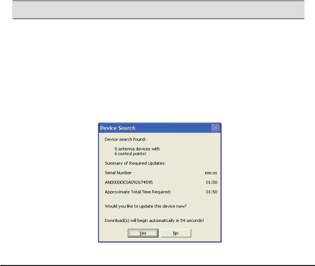
Download Phase is new way to install firmware updates. The actuator update status box appears at the end of the first device search (Figure 3-1). Once the updates are made, this status box is not seen again, until new actuator updates are made available.
If any of the actuators require updates, they are listed by serial number and the time needed for installation. Click Yes to confirm updates. If no action is taken, downloads will begin automatically within 60 seconds.
Figure 3-1. Starting Download Phase.
Bulletin 639536 • Revision L |
October 2014 |
3-1 |
Section 3–Uploading Firmware |
ATC200-LITE-USB Teletilt® RET System |
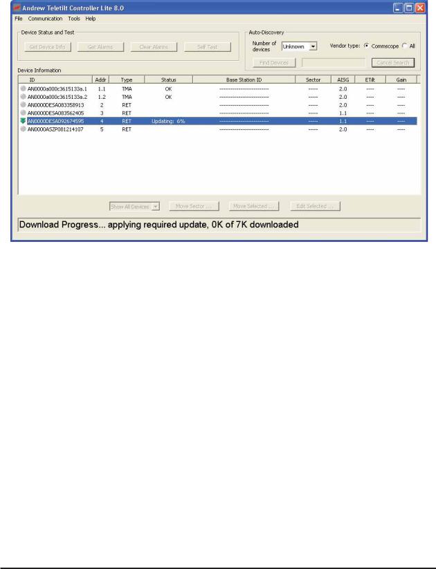
Figure 3-2. Applying Firmware Update .
Firmware updates were placed in the C\:Program Files\Andrew Corporation\ATC Lite directory of the computer when the ATC Lite Setup file is run.
3.2 Installing Firmware updates to TMA devices
Firmware updates are occasionally made to TMA devices. TMA firmware is upgraded by selecting the device from the list following a device scan.
Select the TMA device from list, then right click to view the menu ‘Start firmware update…’ and click or press ENTER to initiate the update. The TMA device that is selected for update is listed with serial number and time needed for update. Click on Yes in the “TMA device firmware update” dialog to proceed with the firmware update (Figure 3-4).
3-2 |
October 2014 |
Bulletin 639536 • Revision L |
 Loading...