


Era™
Medium Power Carrier Access Point
Installation Guide • M0201AJB • October 2018
DISCLAIMER
This document has been developed by CommScope, and is intended for the use of its customers and customer support personnel. The information in this document is subject to change without notice. While every effort has been made to eliminate errors, CommScope disclaims liability for any difficulties arising from the interpretation of the information contained herein. The information contained herein does not claim to cover all details or variations in equipment, nor to provide for every possible incident to be met in connection with installation, operation, or maintenance. This document describes the performance of the product under the defined operational conditions and does not cover the performance underadverseordisturbedconditions.Shouldfurtherinformationbedesired,orshouldparticularproblemsarisewhichare not covered sufficiently for the purchaser's purposes, contact CommScope.
CommScope reserves the right to change all hardware and software characteristics without notice.
COPYRIGHT
© 2018 CommScope, Inc. All Rights Reserved.
This document is protected by copyright. No part of this document may be reproduced, stored in a retrieval system, or transmitted, in any form or by any means, electronic, mechanical photocopying, recording, or otherwise without the prior written permission of CommScope.
For patents see www.cs-pat.com.
TRADEMARKS
All trademarks identified by ® or ™ are registered trademarks or trademarks, respectively, of CommScope, Inc. Names of other products mentioned herein are used for identification purposes only and may be trademarks and/or registered trademarks of their respective companies.
Andrew Wireless Systems GmbH, 12-October-2018

TABLE OF CONTENTS |
|
Document Overview.................................................................................................................................................................................. |
1 |
Document Revision History.............................................................................................................................................................................. |
1 |
Document Cautions and Notes......................................................................................................................................................................... |
2 |
Abbreviations Used in this Guide..................................................................................................................................................................... |
3 |
CommScope Part Numbers .............................................................................................................................................................................. |
3 |
Era System Overview................................................................................................................................................................................. |
4 |
CAP M Overview........................................................................................................................................................................................ |
5 |
Connectors and LED for the CAP M.................................................................................................................................................................. |
6 |
Notch-Filter Connectors ................................................................................................................................................................................... |
7 |
CAP M Hardware Options................................................................................................................................................................................. |
7 |
Single Mounting Bracket............................................................................................................................................................................ |
7 |
Dual Mounting Bracket .............................................................................................................................................................................. |
8 |
Pole Mounting Kit for Up to 18" Poles....................................................................................................................................................... |
8 |
Hybrid Fiber Splice Box............................................................................................................................................................................... |
8 |
OCTIS Kits................................................................................................................................................................................................... |
8 |
Safely Working with Era Hardware ............................................................................................................................................................ |
9 |
RF Safety Cautions............................................................................................................................................................................................ |
9 |
Health and Safety Precautions ......................................................................................................................................................................... |
9 |
Property Damage Warnings ............................................................................................................................................................................. |
9 |
General Installation Safety Requirements...................................................................................................................................................... |
10 |
Guard Against Damage from Electro-Static Discharge................................................................................................................................... |
10 |
Compliance..................................................................................................................................................................................................... |
11 |
Equipment Symbols Used / Compliance......................................................................................................................................................... |
13 |
Installing CAP Ms..................................................................................................................................................................................... |
14 |
CAP M Installation and Cascade Rules............................................................................................................................................................ |
14 |
Cat6A Cable Requirements for Ethernet Devices........................................................................................................................................... |
15 |
Prepare for Installation................................................................................................................................................................................... |
15 |
Recommended Tools and Material.......................................................................................................................................................... |
15 |
Determine the Power Consumption of the CAPM.................................................................................................................................. |
16 |
Determine the Mounting Site .................................................................................................................................................................. |
16 |
Unpack and Inspect the CAP M and Optional Accessories....................................................................................................................... |
19 |
Wire an Optional Hybrid Fiber Splice Box....................................................................................................................................................... |
19 |
Mount the CAPM........................................................................................................................................................................................... |
23 |
General Mounting Cautions..................................................................................................................................................................... |
23 |
Mounting Orientation ............................................................................................................................................................................. |
24 |
Mount the CAPM to a Wall or Vertical Surface....................................................................................................................................... |
25 |
Mount a CAP M Using a Single Mounting Bracket............................................................................................................................. |
25 |
Mount Two CAP Ms Using a Dual Mounting Bracket......................................................................................................................... |
31 |
Mount the CAPM to a 4" to 18" Pole...................................................................................................................................................... |
39 |
Attach a Hybrid FiberSplice Box to the CAP M........................................................................................................................................ |
42 |
Attaching a Hybrid Fiber Splice Box for a Single Mount Installation ................................................................................................. |
42 |
Attaching a Hybrid Fiber Splice Box for a Dual Mount Installation.................................................................................................... |
44 |
Grounding the CAP M..................................................................................................................................................................................... |
46 |
Connect the CAP M Cables............................................................................................................................................................................. |
47 |
Obtain the Required Cable Material........................................................................................................................................................ |
47 |
Connect the CAP M to an RF Antenna...................................................................................................................................................... |
48 |
Connect the CAP M to a Classic CAN or TEN............................................................................................................................................ |
48 |
Connect a Secondary CAP M (Optional)................................................................................................................................................... |
48 |
Connect an External Ethernet Device (Optional)..................................................................................................................................... |
49 |
Power the CAP M............................................................................................................................................................................................ |
49 |
CAP M AC Power Cable ............................................................................................................................................................................ |
50 |
CAP M DC Power Cable............................................................................................................................................................................ |
50 |
Connect the CAP M Power ...................................................................................................................................................................... |
51 |
Connect the Mains Power to the CAP M........................................................................................................................................... |
51 |
Connect a Hybrid Fiber Splice Box..................................................................................................................................................... |
52 |
Power the CAP M..................................................................................................................................................................................... |
52 |
M0201AJB |
Era™ Medium Power Carrier Access Point Installation Guide |
© October 2018 CommScope, Inc. |
Page iii |
|
|

Contacting CommScope........................................................................................................................................................................... |
53 |
DCCS Global Technical Support...................................................................................................................................................................... |
53 |
Telephone Helplines................................................................................................................................................................................. |
53 |
Online Support......................................................................................................................................................................................... |
53 |
Waste Electrical and Electronic Equipment Recycling.................................................................................................................................... |
53 |
Hardware to Software Mapping Information................................................................................................................................................. |
54 |
DCCS Technical Training ................................................................................................................................................................................. |
54 |
Accessing Era User Documentation................................................................................................................................................................ |
55 |
Era™ Medium Power Carrier Access Point Installation Guide |
M0201AJB |
Page iv |
© October 2018 CommScope, Inc. |
|
|
DOCUMENT OVERVIEW
This installation guide provides a product overview of and installation instructions for the Medium Power Carrier Access Point (CAP M), which allows transmission between Era equipment, antennas, and Ethernet devices (such as WiFi and IP cameras).
Table 1 lists the CAP M models that this installation guide supports.
|
Table 1. Supported CAP M Models |
|
|
|
|
Part Number 1 |
|
Model Name |
|
|
|
7781125-000x |
|
CAP M 9/18/21/26 |
|
|
|
7820478-000x |
|
CAP M 7E/80-85/17E/19 |
|
|
|
1The“-000x”suffixprovidesinformationastowhethertheCAP M isACorDC. Contact your local sales representative for further information. See also "CommScope Part Numbers” on page 3.
For information on other Era system components, refer to the Era™ software and hardware user documentation, which can be accessed on the CommScope DCCS Customer Portal (see "Accessing Era User Documentation” on page 55.)
For information on how to find the minimum software requirements for Era hardware, refer to "Hardware to Software Mapping Information” on page 54.
Document Revision History
This is the second release of the Medium Power Carrier Access Point Installation Guide, which:
•adds support for the new Era system configuration and WCS Subrack functions and modes that were introduced in Era Software Version 2.5; for an overview see"Era System Overview” on page 4
•updates Figure 1 on page 5, which shows an Era system in which the CAP Ms connect to a Classic CAN
•updates "Recommended Tools and Material” on page 15
•updates "General Mounting Cautions” on page 23
•updates "Mount a CAP M Using a Single Mounting Bracket” on page 25 and "Mount Two CAP Ms Using a Dual Mounting Bracket” on page 31—the M6x12 screw now requires an M6 plain washer and an M6 split-lock washer
•adds "Pole Mounting Kit for Up to 18" Poles” on page 8 and "Mount the CAP M to a 4" to 18" Pole” on page 39.
M0201AJB |
Era™ Medium Power Carrier Access Point Installation Guide |
© October 2018 CommScope, Inc. |
Page 1 |
|
|

Document Overview
Document Cautions and Notes
This document may contain any of the following notes, cautions, and warning icons.
Theicontotheleftisusedtoindicateacautionorwarning.Cautionsandwarningsindicateoperationsor steps that could cause personal injury, induce a safety problem in a managed device, destroy or corrupt information, or interrupt or stop services.
 The icon to the left indicates a caution or warning that pertains to laser equipment.
 The icon to the left indicates a caution or warning that pertains to Radio Frequency (RF).
 The icon to the left indicates that the hardware is susceptible to Electro-Static Discharge (ESD) damage.
 The icon to the left indicates a caution or warning that pertains to an electrical hazard.
 The icon to the left indicates a caution or warning that pertains to a fire hazard.
The icon to the left indicates a Note. Notes provide information about special circumstances.
Era™ Medium Power Carrier Access Point Installation Guide |
M0201AJB |
Page 2 |
© October 2018 CommScope, Inc. |
|
|

|
|
|
Document Overview |
Abbreviations Used in this Guide |
|
||
AC |
Alternating Current |
Gb |
Gigabyte |
AP |
Access Point |
GHz |
Gigahertz |
AUX |
Auxiliary |
GUI |
Graphical User Interface |
C |
Celsius |
ISDE |
Innovation, Sciences et Développement économique Canada |
CAN |
Central Area Node |
ISED |
Innovation, Science and Economic Development Canada |
CAP H |
Carrier Access Point, High Power |
kg |
Kilogram |
CAP L |
Carrier Access Point, Low Power |
LED |
Light Emitting Diode |
CAP M |
Carrier Access Point, Medium Power |
MHz |
Megahertz |
Cat |
Category |
mm |
Millimeter |
CAT |
Copper Transport |
MMF |
Multi-Mode Fiber |
dB |
Decibel |
OPT |
Optical Transport |
dBm |
Decibel-milliwatts |
PN |
Part Number |
DC |
Direct Current |
RAN |
Regional-Area Network |
DC |
Direct Current |
RF |
Radio Frequency |
DCCS |
Distributed Coverage and Capacity Solutions |
RU |
Rack Unit |
EFTA |
European Free Trade Association |
SFP |
Small Form-Factor Pluggable |
EMC |
Electromagnetic Compatibility |
SMF |
Single-Mode Fiber |
EMEA |
Europe, Middle East, Africa |
TEN |
Transport Expansion Node |
EU |
European Union |
UAP |
Universal Access Point |
F |
Fahrenheit |
Vdc |
Volts, direct current |
FCC |
Federal Communications Commission |
W |
Watts |
CommScope Part Numbers
The CommScope part numbers in this installation guide are in the format of nnnnnnn-xx, where the “-xx” suffixindicatesthelatestrelease.ContactyourlocalCommScopesalesrepresentativeforthecurrentrelease part number.
M0201AJB |
Era™ Medium Power Carrier Access Point Installation Guide |
© October 2018 CommScope, Inc. |
Page 3 |
|
|
Era System Overview
ERA SYSTEM OVERVIEW
Era™ coordinates wireless capacity throughout the entire coverage area via a single centralized head-end
locationorfromanoperator’sexistingC-RANhub.BasedonION®-E,Eraoperatesonthesamecost-efficient standardITcablingasION-EandiscompatiblewithION-Edeployments.Erasystemsbringtogetherlicensed wirelessandpower,plusGigabitEthernetforWiFiintoonewirelesssystemthatcanscaletobuildingsizeand is technology and spectrum agnostic and adaptive. An Era system comprises the components listed below.
•Central Area Node (CAN)—provides server-level control and primary signal distribution.It combines the signals from multiple operators and distributes those signals within a venue or multiple venues. There are two configuration modes available for the CAN: Classic and Switching.
–TheClassic CAN configurationisappropriateforwhenalltheBTSandBasebandsourcesarelocated in a centralized space in the same venue as the Classic CAN. You install RF Donor (RFD) Cards and CPRIDigitalDonor(CDD)CardsinaClassicCAN,whichdigitizestheanalogBTSsignalsfromtheRFD CardsandcombinesthosewiththeBBUCPRIdigitalsignalsfromtheCDDCards,andthendistributes the RF signals to the TENs. The TENs then provide the RF signals to the Access Points (APs). The ClassicCANalsosupportsAPsthataredirectlyconnectedtoCATorOPTCardsinstalledintheClassic CANchassis.Wide-areaIntegrationNodes(WINs)arenotsupportedbyaClassicCAN.Usershavefull and flexible control of all signal routing via the Era GUI.
–The Switching CAN configuration is appropriate for when WINs are required to allow operators to bring in baseband signals from multipleremotelocationstofullyleveragetheC-RANarchitecture in their hubs. All operator Baseband signals (analog BTS and BBU CPRI) are supplied to the Switching CANby theWINs, so noRFDor CDD Cardscan beinstalledinthe SwitchingCAN.TheSwitchingCAN then combines the signals from all WINs and distributes those signals to the TENs, and the TENs providethesignalstotheAPs.APsarenotdirectlyconnectedtoaSwitchingCAN.Usershavefulland flexible control of all signal routing via the Era GUI.
Thisguideuses“CAN”tocollectivelyrefertoCentralAreaNodes.Wheninformationpertainstoaspecific
CAN mode, “Classic CAN” and “Switching CAN” will be used.
•Wide-Area Integration Node (WIN)—interfaces between a Switching CAN and RF sources, which makes C-RAN possible in Era by allowing operators to bring in signals from multiple remote locations kilometersaway.YouinstallRFDandCDDCardsintheWIN,whichtakestheanalogBTSsignalsfromthe RFDCardsandcombinesthosewiththeBBUCPRIdigitalsignalsfromtheCDDCards,anddistributesthe RF sources to a Switching CAN.
•Transport Expansion Node (TEN)—is an expansion node connected to the CAN via fiber and can be located throughout the venue coverage area. A single TEN can support, dependent on the AP type and poweringmethod,12to32AccessPoints(APs),whichgreatlyreducesthenumberoffiberrunsbetween the head-end and each AP.
•Access Point (AP)—connects a Classic CAN or TEN to antennas or other wireless devices. On the downlink, an APconvertsdata arrivingat the APto analogsignals andsends them toanantenna. On the uplink, received signals are digitized and serialized into data streams which are sent back to the Classic CANorTEN.APssupportGigabitEthernetpass-throughforWiFi,IPcameras,orotherdevicesinaddition towirelessoveracommoncable.AnAPcanbeanyoftheUniversalAccessPointsorCarrierAccessPoints.
This guide uses “Access Point (AP)” to collectively refer to the Universal Access Points (UAPs) and the Carrier Access Point (CAPs), and “Fiber APs” to collectively refer to Fiber CAP Ls and CAP Ms. When information pertains to a specific AP type, that AP will be identified.
Era™ Medium Power Carrier Access Point Installation Guide |
M0201AJB |
Page 4 |
© October 2018 CommScope, Inc. |
|
|

CAP M Overview
CAP M OVERVIEW
This installation guide describes the Medium Power Carrier Access Point (CAP M), which interfaces via an optical link withaClassicCAN,or with aTEN. This allowsthe CAPM toprovidedataoverSingle-ModeFiber (SMF), or Multi-Mode Fiber (MMF). Power for CAP Ms is provided over embedded AC/DC (AC version) or remotely through hybrid fiber (DC version).
On the downlink, the CAP M converts data arriving at the CAP M to analog signals and sends them to the Antenna port. On the uplink, received signals are digitized and serialized into data streams, which are sent backtotheClassicCANorTEN.EachCAP McanprovideRFcoverageforuptofourspecificfrequencybands. Figure 1 shows how a CAPM can be deployed in an Era system.
Figure 1. CAP M in an Era System using a Classic CAN
All APs can only connect to a TEN or a Classic CAN. APs cannot connect to a Switching CAN or to a WIN.
The CAP M
•is passively cooled and operates within the following temperature ranges: -33°C to +52°C (-27.4°F to 125.6°F)
•is rated for indoor and outdoor (IP66) installations; see"Determine the Mounting Site” on page 16
•hasatypicalpowerconsumptionof140W;seealso"DeterminethePowerConsumptionoftheCAP M”on page 16.
M0201AJB |
Era™ Medium Power Carrier Access Point Installation Guide |
© October 2018 CommScope, Inc. |
Page 5 |
|
|

CAP M Overview
Connectors and LED for the CAP M
Figure 2 and Table 2 identify the CAP M connectors and its LED; corresponding connectors are shown.
 Do not remove caps from any of the connectors until instructed to do so.
|
|
|
|
|
|
|
|
|
|
|
|
|
|
|
|
|
|
|
|
|
|
|
|
|
|
|
|
|
|
|
|
|
|
|
|
|
|
|
|
|
|
|
|
|
|
|
|
|
|
|
|
|
|
|
|
|
|
|
|
|
|
|
|
|
|
|
|
|
|
|
|
|
|
|
|
|
|
|
|
|
|
|
|
|
|
|
|
|
|
|
|
|
|
1 |
2 |
3 |
4 |
5 |
6 |
7 |
|
||||||
|
|
|
|
|
|
|
Figure 2. CAP M Connectors and LED |
|
|
|
|
||||||
|
|
|
|
|
Table 2. Function of the CAP M Connectors and LED |
|
|
|
|
||||||||
|
|
|
|
|
|
|
|
|
|
|
|
|
|
|
|
|
|
REF # |
Label |
Description |
Function |
|
|
|
|
|
|
|
|
|
|
|
|
||
|
|
|
|
|
|
|
|
|
|
|
|
||||||
1 |
A |
RJ45Auxiliary |
Connects to external Ethernet devices such as WiFi and IP cameras. Cabling is via the appropriate CAT |
||||||||||||||
|
|
|
port |
cablefortheprotocol;thismodelsupportsa1000BASE-Tand802.3atClass4PoweroverCat6AEthernet |
|||||||||||||
|
|
|
|
connection. Maximum attached cable length is 3 meters (9.8 feet). For information on the Auxiliary port |
|||||||||||||
|
|
|
|
in cascades, see "CAP M Installation and Cascade Rules” on page 14. Port A ships with factory-installed |
|||||||||||||
|
|
|
|
EMI/weatherproof plug and must remain plugged if not in use. (Graphic shows the port populated with |
|||||||||||||
|
|
|
|
an OCTIS Ethernet connector PN 7760652 which must be ordered separately—see "OCTIS Kits” on |
|||||||||||||
|
|
|
|
page 8.) |
|
|
|
|
|
|
|
|
|
|
|
|
|
|
|
|
|
|
|
|
|
|
|
|
|
||||||
2 |
2 |
|
Optical Port 2 |
If the CAP M is functioning as a Primary CAP M in a cascade, Optical Port 2 connects to Optical Port 1 of |
|||||||||||||
|
|
|
|
the Secondary CAP M via the Optical OCTIS Kit (PN 7770612), which ships with the unit, to provide the |
|||||||||||||
|
|
|
|
mainsignalinterface.OpticaltransportoccursoverSingleModeFiber(SMF)orMultiModeFiber(MMF). |
|||||||||||||
|
|
|
|
Port2shipswithfactory-installedEMI/weatherproofplugandmustremainpluggedifnotinuse.Graphic |
|||||||||||||
|
|
|
|
shows the OCTIS connector in blue. |
|
|
|
|
|
|
|||||||
|
|
|
|
|
|
|
|
|
|
|
|
||||||
3 |
1 |
|
Optical Port 1 |
Connects to a Classic CAN or TEN (possibly through a local Hybrid Fiber Junction Box) and provides the |
|||||||||||||
|
|
|
|
main signal interface; if Secondary CAP M in a cascade, Optical Port 1 connects to Optical Port 2 of the |
|||||||||||||
|
|
|
|
PrimaryCAP M.Opticaltransportoccursover SingleModeFiber(SMF)orMulti ModeFiber(MMF).Uses |
|||||||||||||
|
|
|
|
the Optical OCTIS Kit (PN 7770612), which ships with the unit. Port 1 ships with a dust cap that can be |
|||||||||||||
|
|
|
|
discarded upon unit installation. Graphic shows the OCTIS connector in blue. |
|
|
|
||||||||||
|
|
|
|
|
|
|
|
|
|
|
|
|
|
|
|||
4 |
Unlabeled |
Power LED |
See "Power the CAP M” on page 52. |
|
|
|
|
|
|
||||||||
|
|
|
|
|
|
|
|
|
|
|
|
||||||
5 |
ANT |
4.3-10 RF |
Transmits and receiving signals to and from distributed antennas. This RF port can be connected directly |
||||||||||||||
|
|
|
connector |
toanantenna(usingRFjumpercables)orthroughsplitters,allowingadditionalantennastobefedbythe |
|||||||||||||
|
|
|
|
CAP M. |
|
|
|
|
|
|
|
|
|
|
|
|
|
|
|
|
|
|
|
|
|
|
|
|
|
|
|
|
|
|
|
6 |
Unlabeled |
Grounding |
Connects the CAP M to an approved earth-ground source. |
|
|
|
|
||||||||||
|
|
|
bolts |
|
|
|
|
||||||||||
|
|
|
|
|
|
|
|
|
|
|
|
|
|
|
|
|
|
|
|
|
|
|
|
|
|
|
|
|
|
|
|
||||
7 |
Mains |
Power |
Connects to any of the following (graphic shows the port populated): |
|
|
|
|
||||||||||
|
|
|
connector |
• Vac—Main power |
|
|
|
|
|
|
|
|
|||||
|
|
|
(Vac or Vdc) |
|
|
|
|
|
|
|
|
||||||
|
|
|
• Vdc—Remote DC power supply or a Hybrid Fiber Junction Box. |
|
|
|
|
||||||||||
|
|
|
|
|
|
|
|
|
|
|
|
|
|
|
|
|
|
Era™ Medium Power Carrier Access Point Installation Guide |
M0201AJB |
Page 6 |
© October 2018 CommScope, Inc. |
|
|
CAP M Overview
Notch-Filter Connectors
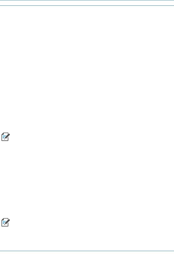
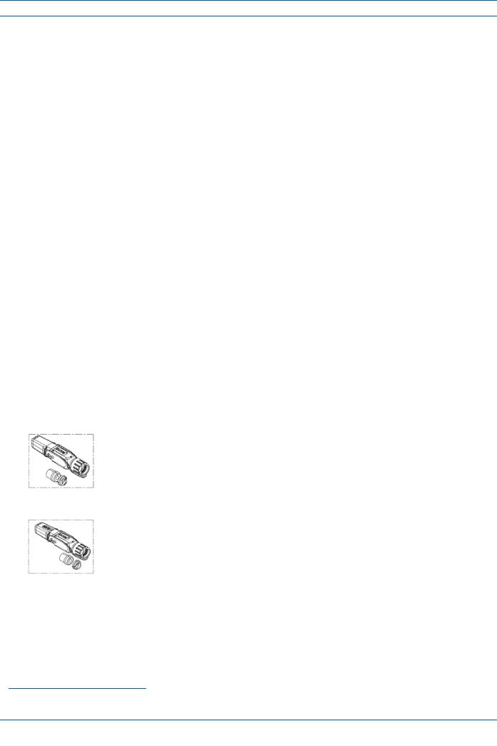
The CAP M 7E/80-85/17E/19 has two Notch-Filter connectors that are reserved for future use. The connectors,whichareclosedby a jumper,haveaprotective cover.Do not remove the protective cover or interfere with the jumper.
Protec ve cover over the
Notch-Filter connectors
Notch-Filter connectors closed with a jumper
Figure 3. Notch-Filter Connector on the CAP M 7E/80-85/17E/19
CAP M Hardware Options
The following sections describe hardware options for the CAP M.
Single Mounting Bracket
The Single Mounting Bracket (CommScope PN 7821954-xx) provides the mounting brackets required to mountanCAP Mtoawallorothervertical,flatsurface.See"MountaCAP MUsingaSingleMountingBracket” on page 25.
M0201AJB |
Era™ Medium Power Carrier Access Point Installation Guide |
© October 2018 CommScope, Inc. |
Page 7 |
|
|
CAP M Overview
Dual Mounting Bracket
The Dual Mounting Bracket (CommScope PN 7821955-xx) provides the mounting brackets required to mount two CAP Ms back-to-back in a single bracket, which is then mounted to a wall or other vertical, flat surface. See "Mount Two CAP Ms Using a Dual Mounting Bracket” on page 31.
Pole Mounting Kit for Up to 18" Poles
TheCAP MPoleMountingKitforUpto18"Poles(CommScopePN7692096-XX)isusedtomountaCAP Mto a pole with a circumference of 4" to 18" (10.2 cm to 45.8 cm). See "Mount the CAP M to a 4" to 18" Pole” on page 39.
Hybrid Fiber Splice Box
The Hybrid Fiber Splice Box (CommScope PN 7693816-xx) separates the power from the fiber signals on a hybrid fiber feed from the Classic CAN or TEN. It feeds power to the CAPM through a composite cable that includes bothfiber andcopper powerwires. Fiberandcopperterminate at theSplice Box, which allows you to separate the DC wires and fiber at the remote end. For CAPMs, you will typically use composite cable to transportsignalandpower,andthenusetheHybridFiberSpliceBoxtoterminatethefiberattheCAP M.See "Wire an Optional Hybrid Fiber Splice Box” on page 19.
OCTIS Kits
All CAP Ms include one OCTIS1 Kit for the primary interface to the Classic CAN or TEN that CAP M plugs into the CAP M Optical Port 1. You can order an additional OCTIS Kit, which would allow you to cascade two CAPMsviaOpticalPort2,ortoattachanauxiliaryEthernetdeviceviatheAUXPort.Table 3identifiesthetwo OCTIS Kit options.
Table 3. CAP M OCTIS Kits
Kit Name |
CommScope PN |
Description |
|
|
|
Optical OCTIS Kit |
7770612 |
ThisistheSFP+connectorthatyouusetocascadeaSecondaryFiber |
|
|
CAP L; one Optical OCTIS Kit ships with each Fiber CAP L. Use as |
|
|
follows: |
|
|
• Optical Port 1—to connect the CAP M to a Classic CAN or TEN. |
|
|
• Optical Port 2—to cascade a second CAP M. |
|
|
• SFP+ Module must be ordered separately, it is not included as |
|
|
part of the Optical OCTIS Kit. |
|
|
|
Ethernet OCTIS Kit |
7760652 |
This is the RJ-45 connector that you use to attach an auxiliary |
|
|
Ethernet device. The Ethernet OCTIS Kit must be ordered |
|
|
separately. |
|
|
|
1 OCTIS is a trademark of RADIALL.
Era™ Medium Power Carrier Access Point Installation Guide |
M0201AJB |
Page 8 |
© October 2018 CommScope, Inc. |
|
|

Safely Working with Era Hardware
SAFELY WORKING WITH ERA HARDWARE
The following sections provide important information that you should read and know before working with any Era hardware. Observe all cautions and warnings listed in this section.
RF Safety Cautions
This system is a RF Transmitter and continuously emits RF energy. Maintain a minimum 8-inch (20 cm) clearancefromtheantennawhilethesystemisoperating.Wheneverpossible,shutdowntheRANbefore servicing the antenna.
 Only license holders for the respective frequency range are allowed to operate this unit.
Health and Safety Precautions
A high leakage current ground (earth) connection to the Power Supply Unit (PSU) is essential before making any other connections to the PSU.
Laser radiation. Risk of eye injury in operation. Do not stare into the laser beam; do not view the laser beam directly or with optical instruments.
High frequency radiation in operation. Risk of health hazards associated with radiation from the antenna(s) connected to the unit. Implement prevention measures to avoid the possibility of close proximity to the antenna(s) while in operation.
Property Damage Warnings
 Keep operating instructions within easy reach and make them available to all users.
 Only license holders for the respective frequency range are allowed to operate this unit.
Readandobeyallthewarninglabelsattachedtotheunit.Makesurethatallwarninglabelsarekeptina legible condition. Replace anymissing or damaged labels.
Make sure the unit's settings are correct for the intended use (refer to the manufacturer product information) and regulatory requirements are met. Do not carry out any modifications or fit any spare parts, which are not sold or recommended by the manufacturer.
Duetopowerdissipation,theCAP Mmayreachaveryhightemperature.Donotoperatethisequipment on or close to flammable materials. Use caution when servicing the CAP M.
M0201AJB |
Era™ Medium Power Carrier Access Point Installation Guide |
© October 2018 CommScope, Inc. |
Page 9 |
|
|

Safely Working with Era Hardware
 Only authorized and trained personnel are allowed to open the unit and get access to the inside.
Only suitably qualified personnel are allowed to work on this unit and only after becoming familiar with allsafetynotices,installation,operationandmaintenanceprocedurescontainedinthisinstallationguide.
Although the unit is internally protected against overvoltage,it is strongly recommended to ground (earth)theantennacablesclosetotheantennaconnectorsoftheunitforprotectionagainstatmospheric discharge. In areas with strong lightning, it is strongly recommended to install additional lightning protection.
General Installation Safety Requirements
Wetconditionsincreasethepotentialforreceivinganelectricalshockwheninstallingorusingelectrically powered equipment. To prevent electrical shock, never install or use electrical equipment in a wet location or during a lightning storm.
This system is a RF Transmitter and continuously emits RF energy. Maintain a minimum 8-inch (20 cm) clearancefromtheantennawhilethesystemisoperating.Wheneverpossible,shutdowntheRANbefore servicing the antenna.
 Do not remove caps from any of the connectors until instructed to do so.
The CAP M is to be used only with CommScope (NEC Class 2) or Limited Power Source Era Subrack, or equivalent.
Read and observe all the warning labels attached to the unit. Make sure that all warning labels are kept in a legible condition. Replace any missing or damaged labels.
Guard Against Damage from Electro-Static Discharge
Electro-Static Discharge (ESD) can damage electronic components. To prevent ESD damage, always wear an ESD wrist strap when working with Era hardware components. Not all Era hardware requires grounding.Forthosehardwarecomponentsforwhichgroundingisrequired,connectthegroundwireon the ESD wrist strap to an earth ground source before touching the component. Wear the wrist strap the entire time that you work with the hardware.
Era™ Medium Power Carrier Access Point Installation Guide |
M0201AJB |
Page 10 |
© October 2018 CommScope, Inc. |
|
|

Safely Working with Era Hardware
Compliance
1Notice: For installations, which have to comply with FCC RF exposure requirements, the antenna selectionandinstallationmustbecompletedinawaytoensurecompliancewiththoseFCCrequirements. DependingontheRFfrequency,ratedoutputpower,antennagain,andthelossbetweentherepeaterand antenna, the minimum distance D to be maintained between the antenna location and human beings is calculated according to this formula:
D[cm] = |
P[mW ] |
|
|
4 π PD |
2 |
] |
|
|
[mW /cm |
||
where
•P(mW)istheradiatedpowerattheantenna,i.e.themax.ratedrepeateroutputpowerinadditionto the antenna gain minus the loss between the repeater and the antenna.
•PD (mW/cm²) is the allowed Power Density limit acc. to 47 CFR 1.1310 (B) for general population / uncontrolled exposures which is
–f (MHz) / 1500 for frequencies from 300MHz to 1500MHz
–1 for frequencies from 1500MHz to 100,000MHz
RFexposurecompliancemayneedtobeaddressedatthetimeoflicensing,asrequiredbytheresponsible
FCC Bureau(s), including antenna co-location requirements of 1.1307(b)(3).
2Notice: For installations which have to comply with European EN50385 exposure compliance requirements, the following Power Density limits/guidelines (mW/cm²) according to ICNIRP are valid:
•0.2 for frequencies from 10 MHz to 400 MHz
•F (MHz) / 2000 for frequencies from 400 MHz to 2 GHz
•1 for frequencies from 2 GHz to 300 GHz
3Notice: Installation of this equipment is in full responsibility of the installer, who has also the responsibility,thatcablesandcouplersarecalculatedintothemaximumgainoftheantennas,sothatthis value, which is filed in the FCC Grant and can be requested from the FCC data base, is not exceeded. The industrialboostersareshippedonlyasanakedboosterwithoutanyinstallationdevicesorantennasasit needs for professional installation.
4Notice: For installations which have to comply with FCC/ISED requirements:
English:
This device complies with FCC Part 15. Operation is subject to the following two conditions: (1) this device may not cause interference, and (2) this device must accept any interference, including interference that may cause undesired operation of the device.
ThisdevicecomplieswithHealthCanada'sSafetyCode.TheinstallerofthisdeviceshouldensurethatRF radiation is not emitted in excess of the Health Canada's requirement. Information can be obtained at http://www.hc-sc.gc.ca/ewh-semt/pubs/radiation/radio_guide-lignes_direct-eng.php.
Changesormodificationsnotexpresslyapprovedbythepartyresponsibleforcompliancecouldvoidthe user's authority to operate the equipment.
Antenna Stmt for ISED:
Thisdevicehasbeendesignatedtooperatewiththeantennashavingamaximumgainof9dBi.Antennas having a gain greater than 9 dBi are prohibited for use with this device without consent by ISED regulators. The required antenna impedance is 50 ohms.
Theantenna(s)usedforthistransmittermustbeinstalledtoprovideaseparationdistanceofatleast100 cm from all persons and must not be co-located or operating in conjunction with any other antenna or
M0201AJB |
Era™ Medium Power Carrier Access Point Installation Guide |
© October 2018 CommScope, Inc. |
Page 11 |
|
|

Safely Working with Era Hardware
transmitter.Usersandinstallersmustbeprovidedwithantennainstallationinstructionsandtransmitter operating conditions for satisfying RF exposure compliance.
French:
CetappareilestconformeàFCCPartie15.SonutilisationestsoumiseàLesdeuxconditionssuivantes:(1) cetappareilnepeutpasprovoquerd'interférenceset(2)cetappareildoitaccepterTouteinterférence,y compris les interférences qui peuvent causer un mauvais fonctionnement du dispositif.
Cet appareil est conforme avec SantéCanada Code de sécurité6. Le programme d'installation de cet appareildoits'assurerquelesrayonnementsRFn'estpasémisau-delàdeI'exigencedeSantéCanada.Les informations peuvent être obtenues: http://www.hc-sc.gc.ca/ewh-semt/pubs/radiation/radio_guide-lignes_direct-eng.php
Les changements ou modifications non expressément approuvés par la partie responsable de la conformitépourraient annuler l'autoritéde l'utilisateur àutiliser cet équipement.
Antenne Stmt pour ISDE:
Cedispositifa étédésignépourfonctionneraveclesantennesayant ungainmaximalde9dBi. Antennes ayant un gain plus grand que 9 dBi sont interdites pour une utilisation avec cet appareil sans le consentement des organismes de réglementation d'ISDE. L'impédance d'antenne requise est 50 ohms.
L'antenne (s) utilisépour cet émetteur doit être installépour fournir une distance de séparation d'au moins100cmdetouteslespersonnesetnedoitpasêtreco-localiséesouopérantenconjonctionavecune autreantenneouémetteur.Lesutilisateursetlesinstallateursdoiventêtrefournisavecdesinstructions d'installation de l'antenne et des conditions de fonctionnement de l'émetteur pour satisfaire la conformitéaux expositions RF.
5Notice: The unit complies with Overvoltage Category II. It also complies with the surge requirement according to EN 61000-4-5 (fineprotection); however, installation of an additional medium (via local supplyconnection)and/orcoarseprotection(externalsurgeprotection)isrecommendeddependingon the individual application in order to avoid damage caused by overcurrent.
For Canada and US, components used to reduce the Overvoltage Category shall comply with the requirements of IEC 61643-series. As an alternative, components used to reduce the Overvoltage Category may comply with ANSI/IEEE C62.11, CSA Certification Notice No. 516, CSA C22.2 No. 1, or UL 1449. Suitability of the component for the application shall be determined for the intended installation.
6Notice: Corresponding local particularities and regulations must be observed. For national deviations, please refer to the respective documents included in the manual CD that is delivered with the unit.
7Note: For a Class B digital device or peripheral:
ThisequipmenthasbeentestedandfoundtocomplywiththelimitsforaClassBdigitaldevice,pursuant to part 15 of the FCC Rules. These limits are designed to provide reasonable protection against harmful interferenceinaresidentialinstallation.Thisequipmentgenerates,usesandcanradiateradiofrequency energyand,ifnotinstalledandusedinaccordancewiththeinstructions,maycauseharmfulinterference toradio communications. However, there is no guarantee thatinterference will not occur in a particular installation.Ifthisequipmentdoescauseharmfulinterferencetoradioortelevisionreception,whichcan be determined by turning the equipment off and on, the user is encouraged to try to correct the interference by one or more of the following measures:
•Reorient or relocate the receiving antenna.
•Increase the separation between the equipment and receiver.
•Connect the equipment into an outlet on a circuit different from that to which the receiver is connected.
•Consult the dealer or an experienced RF technician for help.
Era™ Medium Power Carrier Access Point Installation Guide |
M0201AJB |
Page 12 |
© October 2018 CommScope, Inc. |
|
|

Safely Working with Era Hardware
8Notice: For a Class A digital device or peripheral.
ThisequipmenthasbeentestedandfoundtocomplywiththelimitsforaClassAdigitaldevice,pursuant to Part 15 of the FCC Rules. These limits are designed to provide reasonable protection against harmful interference when the equipment is operated in a commercial environment. This equipment generates, uses, and can radiate radio frequency energy and, if not installed and used in accordance with the instruction manual, may cause harmful interference to radio communications. Operation of this equipment in a residential area is likely to cause harmful interference in which case the user will be required to correct the interference at his own expense.
9Note: This unit complies with European standard EN60950-1 / EN62368-1.
Equipment Symbols Used / Compliance
Please observe the meanings of the following symbols used in our equipment and the compliance warnings listed in Table 4.
|
|
Table 4. Compliance Labels |
|
|
|
Symbol |
Compliance |
Meaning |
|
|
|
|
|
For industrial (Part 20) signal booster: |
— |
FCC |
WARNING: This is NOT a CONSUMER device. It is designed for installation by FCC LICENSEES and |
QUALIFIEDINSTALLERS.YouMUSThave anFCCLICENSEorexpressconsentofanFCC Licenseeto |
||
|
|
operate this device. Unauthorized use may result in significant forfeiture penalties, including |
|
|
penalties in excess of $100,000 for each continuing violation. |
|
|
|
|
|
|
|
|
WARNING:ThisisNOTaCONSUMERdevice.Itisdesignedforinstallationbyaninstallerapproved |
|
|
byanISEDlicensee.YouMUSThaveanISEDLICENCEortheexpressconsentofanISEDlicenseeto |
|
|
operate this device. |
— |
ISED |
AVERTISSEMENT: Ce produit N'EST PAS un appareil de CONSOMMATION. Il est conçu pour être |
|
|
installé par un installateur approuvé par un titulaire de licence d'ISDE. Pour utiliser cet appareil, |
|
|
vousDEVEZdéteniruneLICENCEd'ISDEouavoirobtenuleconsentementexprèsd'untitulairede |
|
|
licence autorisé par ISDE. |
|
|
|
|
|
|
|
|
To be sold exclusively to mobile operators or authorized installers - no harmonized frequency |
|
CE |
bands, operation requires license. Intended use: EU and EFTA countries. |
|
|
Indicates conformity with the RED directive 2014/53/EU and/or RoHS directive 2011/65/EU. |
|
|
|
|
|
|
|
CE |
IndicatesconformitywiththeREDdirective2014/53/EUandRoHSdirective2011/65/EUcertified |
|
by the notified body no. 0700. |
|
|
|
|
|
|
|
M0201AJB |
Era™ Medium Power Carrier Access Point Installation Guide |
© October 2018 CommScope, Inc. |
Page 13 |
|
|

Installing CAP Ms
INSTALLING CAP MS
ThefollowingsectionsguideyouthroughtheinstallationofaCAP M.Payattentiontoallcautionsandfollow the steps in the order presented.
CAP M Installation and Cascade Rules
When cascading a Secondary CAP M or an external Ethernet device such as WiFi or an IP camera, you must observe the following rules.
•You connect CAP Ms to an OPT Card in the Classic CAN or TEN.
–Each OPT Card has four 10 Gbps ports (labeled 1 - 4) for fiber connections.
–You can connect up to 4CAP Ms per OPT Card for a total of 16 Primary and 32 total, per Classic CAN or TEN.
•Inacascade,theCAP MconnecteddirectlytotheClassicCANorTENisthePrimaryCAP M,andtheCAP M that connects to the Primary CAP M is the Secondary CAPM.
•Thetotal320 MHzRFbandwidthissharedbetweenthetwocascadedunits,butcanbesharedunevenly; that is, with more bandwidth going to either the Primary or Secondary CAP M—either CAP M can transmit all the 320 MHz RF bandwidth or any subset of it.
•The Primary andSecondaryCAP Ms power upas soon as power is applied tothem. In a cascade, theGUI discovers and readies the Primary CAPM for RF first, and then the Secondary CAP M will be discovered and readied for RF. For information on the Power LED behavior, see"Power the CAP M” on page 52.
•SMF or MMF connects the CAP M via its Optical Port 1 to the OPT Card.
•When cascading a Secondary CAP M or an external Ethernet device such as WiFi or an IP camera, you must observe the following rules.
–To cascade two CAP Ms, use a fiber-optic cable.
–SMForMMFconnectstheSecondaryCAP MviaitsOpticalPort1tothePrimaryCAP MviaitsOptical Port 2.
–You can connect the following to the Primary CAP M
a Secondary CAP M
an Ethernet device
both a Secondary CAP M and an Ethernet device.
•To add a Secondary AP, you must add an Optical OCTIS kit to the Primary CAPL, see "OCTIS Kits” on page 8.
•To add an Ethernet device, you must add an RJ45 OCTIS kit to the Primary CAP L, see "OCTIS Kits” on page 8.
Era™ Medium Power Carrier Access Point Installation Guide |
M0201AJB |
Page 14 |
© October 2018 CommScope, Inc. |
|
|
 Loading...