

Page 1
TECP-96-614 Issue 3 November 2016
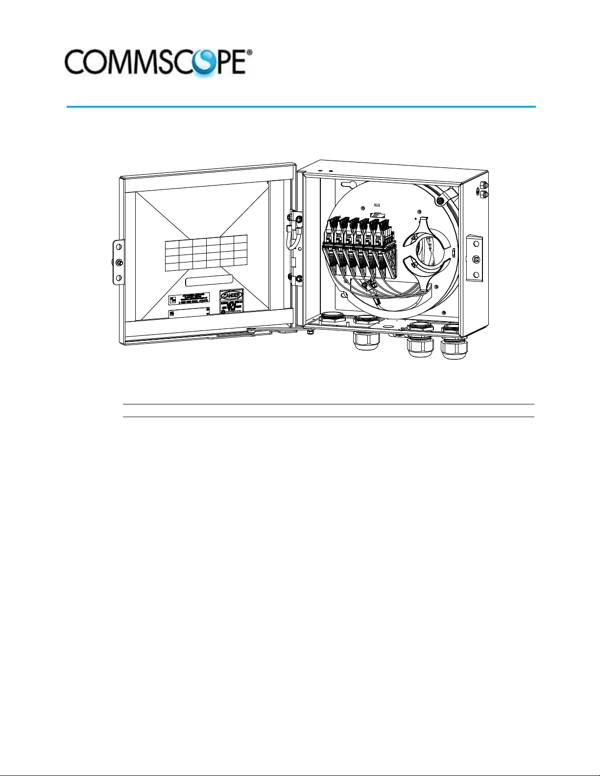
FTTX Solutions Rapid Flexible Fiber Box
User Manual
24691-A
Rapid FFB With RapidReel and Sliding Adapter Packs
Content Page
INTRODUCTION .............................................................................2
Revision History ........................................................................2
Trademark Information ...................................................................2
Admonishments ........................................................................2
1 PRODUCT DESCRIPTION ..................................................................3
1.1 General Description................................................................3
1.2 Main Components .................................................................4
1.3 Bottom Plate Kit .................................................................. 6
1.4 Specifications and Dimensions ........................................................6
2 MOUNTING THE RAPID FFB ................................................................7
2.1 General Recommendations........................................................... 8
2.2 Wooden Utility Pole Mounting Procedure .................................................8
2.3 Metal Utility Pole Mounting Procedure ..................................................10
2.4 Wood-Framed Wall Mounting Procedure ................................................ 11
2.5 Masonry Wall Mounting Procedure .................................................... 14
3 GROUNDING THE RAPID FFB .............................................................. 16
4 OPENING AND CLOSING THE OUTER DOOR..................................................... 17
5 INSTALLING THE FEEDER CABLE............................................................ 18
6 INSTALLING A DROP CABLE ............................................................... 22
(continued)
TECP-96-614 Rev D Page 1
This product is covered by one or more U.S.patents or their foreign equivalents. © 2017 CommScope.
For patents, see http://www.commscope.com/ProductPatent/ProductPatent.aspx All Rights Reserved.
Page 2
TECP-96-614 • Issue 3 • November 2016
Content Page
7 CLEANING CONNECTORS AND ADAPTERS ..................................................... 23
8 ACCESSING ADAPTER PACKS .............................................................. 24
9 PERFORMING A SPLICE .................................................................. 24
10 PRODUCT SUPPORT .................................................................... 26
INTRODUCTION
This manual describes the Rapid Flexible Fiber Box (FFB) and provides all information needed
to install and operate this product. Select the procedures required for the product being installed.
Revision History
ISSUE DATE REASON FOR CHANGE
1 12/2011 Original.
2 3/2012 Details added for paying out feeder cable.
3 November 2016 Rebranded for CommScope.
Trademark Information
CommScope (logo) and CommScope are trademarks.
Admonishments
Important safety admonishments are used throughout this manual. The admonishments must be
followed at all times. These warnings are flagged by use of the triangular alert icon (seen below),
and are listed in descending order of severity of injury or damage and likelihood of occurrence.
Danger: Danger is used to indicate the presence of a hazard that can cause severe personal
injury, death, or substantial property damage if the hazard is not avoided.
Warning: Warning is used to indicate the presence of a hazard that can cause severe personal
injury, death, or substantial property damage if the hazard is not avoided.
Caution: Caution is used to indicate the presence of a hazard that can cause minor personal
injury or property damage if the hazard is not avoided.
General Warning and Caution Statements
Danger: Avoid eye exposure to unmated connectors. Unmated connectors may emit invisible
laser radiation. Do not look directly into the end of a connector or adapter port. Do not inspect
with a magnifying device. To ensure safety, maintain caps on unmated connectors at all times.
Caution: Handle cables with care. Fiber optic cable stubs should be handled with care
throughout the installation procedure to avoid kinking and damage to cables.
Page 2
© 2017 CommScope. All Rights Reserved.
Page 3
1 PRODUCT DESCRIPTION
1.1 General Description
The Rapid Flexible Fiber Box (FFB), shown on the cover of this user manual, is a rugged,
weather-resistant demarcation and aggregation box equipped with an internal RapidReel
cable spool for easy storage, unreeling, and installation of a feeder cable spooled within the
product. The feeder cable may be either stub-ended or terminated with an MPO connector.
Cable length is either 100 feet for a 24-fiber cable or 200 feet for a 12-fiber cable.
The Rapid FFB is used in Fiber-to-the-Cell-Site (FTTCS) and Fiber-to-the-Antenna (FTTA)
applications. In a typical installation, the Rapid FFB is mounted on a utility pole or wall at a cell
site or tower, where it provides a splice or connection point between the backhaul network and
the cell site or tower.
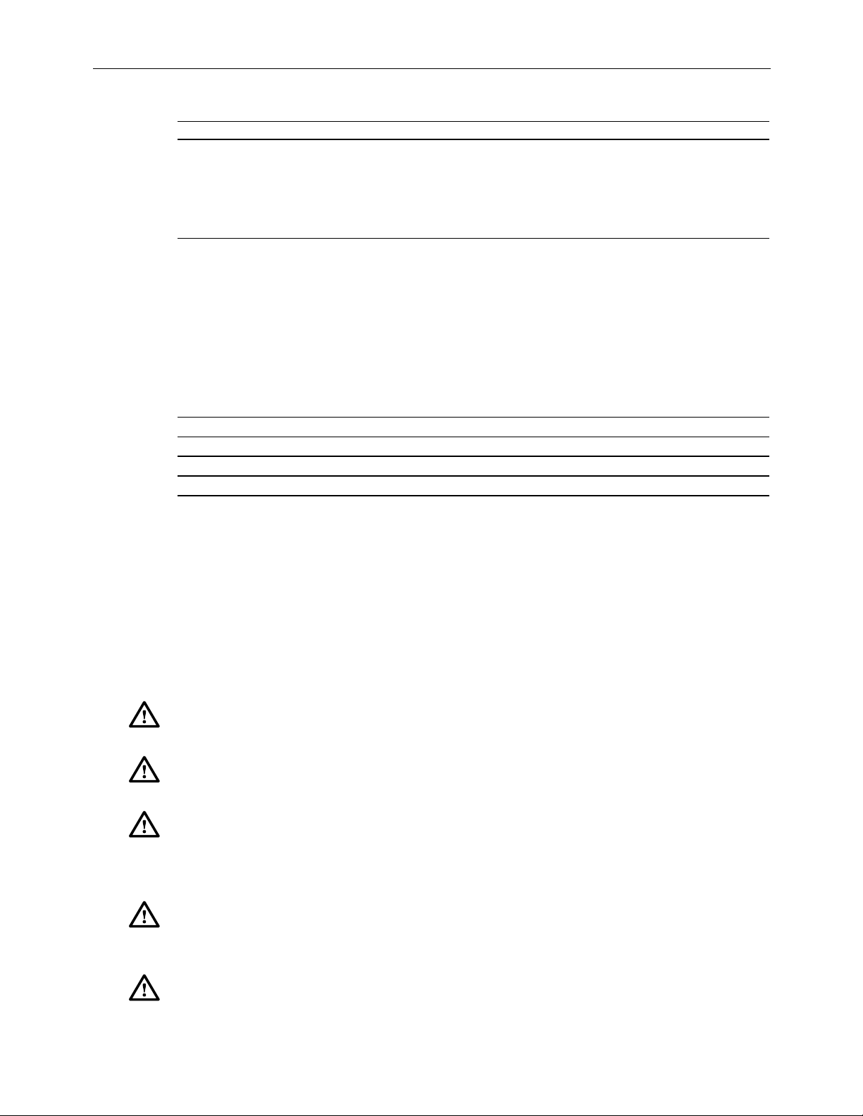
The Rapid FFB divides functionally into feeder cable components and drop cable components,
as shown in
• Feeder Cable Components—include the RapidReel, the feeder cable, and a compression
nut assembly for securing the feeder cable after it is unwound.
Figure 1.
TECP-96-614 • Issue 3 • November 2016
TM
fiber
• Drop Cable Components—consist of two compression nut assemblies for securing drop
cables and either sliding adapter packs or splice trays for terminating the drop cables
within the FFB.
24695-A
FEEDER
COMPONENTS
DROP
COMPONENTS
FROM
BACKHAUL
NETWORK
TO
CELL SITE OR
ANTENNA
Figure 1. Rapid FFB Functional Components
© 2017 CommScope. All Rights Reserved.
Page 3
Page 4
TECP-96-614 • Issue 3 • November 2016
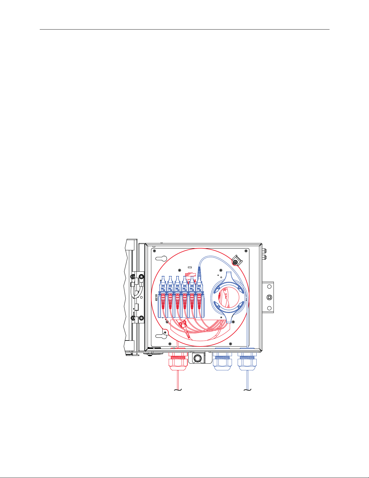
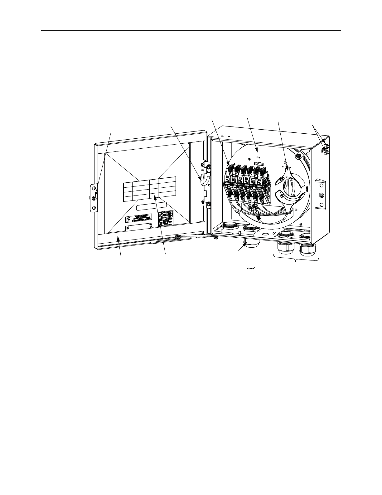
1.2 Main Components
Figure 2 provides a more detailed and comprehensive view of the main components of a Rapid
FFB with a feeder cable pre-wound onto the rapid wheel and with sliding adapter packs for
termination of drop cables.
OUTER
DOOR
LATCH
DOOR
DOOR
GROUNDING
WIRE
DESIGNATION
LABEL
SLIDING
ADAPTER
PACKS
FEEDER CABLE
PORTAL
RAPID
REEL
RADIUS
LIMITERS
DROP SIDE
CABLE PORTALS
GROUNDING
STUDS
24693-A
Figure 2. Main Components of Rapid FFB With Sliding Adapter Packs
The components called out are as follows:
• Outer Door—swings open to provide access to the interior of the box.
• Outer Door Latch—houses a door lock operated with a 216B key tool. It has a hole for an
optional padlock.
• Designation Label—provides an area to record the designation of drop cables.
• Door Grounding Wire—grounds the door to the main part of the box (which is in turn
grounded to the facility ground).
• Sliding Adapter Packs—transition between the feeder cable on the RapidReel and drop
cables. Depending on the fiber count of the feeder cable, the FFB may contain either 12 or
24 adapters.
• RapidReelTM— contains the spooled up feeder cable which is unspooled at the customer
site and routed to the connection point with the cable from the backhaul network. The
RapidReel is locked when shipped and must be unlocked before the cable can be
unwound.
Page 4
© 2017 CommScope. All Rights Reserved.
Page 5

TECP-96-614 • Issue 3 • November 2016
• Radius Limiters—are guides for wrapping around the drop cables when installed. They
prevent the drop cables from being damaged by being bent too sharply.
• Grounding Studs—are used to fasten a two-hole grounding lug and grounding wire.
• Feeder Side Cable Portal—holds the compression nut assembly that is used to secure the
feeder cable after it is unwound.
• Drop Side Cable Portals—holds the compression nut assemblies used to secure drop
cables after they are installed. Multiple cables may enter through the same portal.
Figure 3 shows the splice-specific components of a Rapid FFB with splice trays on the drop
side. This unit also has an internal RapidReel fiber cable spool and feeder cable.
• Radius Limiters—are guides for wrapping around the drop cables when installed. They
prevent the drop cables from being damaged by being bent too sharply.
• Hook-and-Loop Straps—secure the splice trays to the RapidReel and allow the splice
trays to be easily removed from the RapidReel and returned to it after completion of
splicing or other maintenance procedures.
• Splice Trays—are used to splice the feeder cable fibers to the drop cable fibers. The Rapid
FFB accommodates up to
two 12-fiber SC ribbon assemblies
RADIUS
LIMITERS
HOOK-AND-LOOP
STRAP
Figure 3. Main Components of Rapid FFB With Splice Trays
SPLICE
TRAYS
24694-B
© 2017 CommScope. All Rights Reserved.
Page 5
Page 6
TECP-96-614 • Issue 3 • November 2016
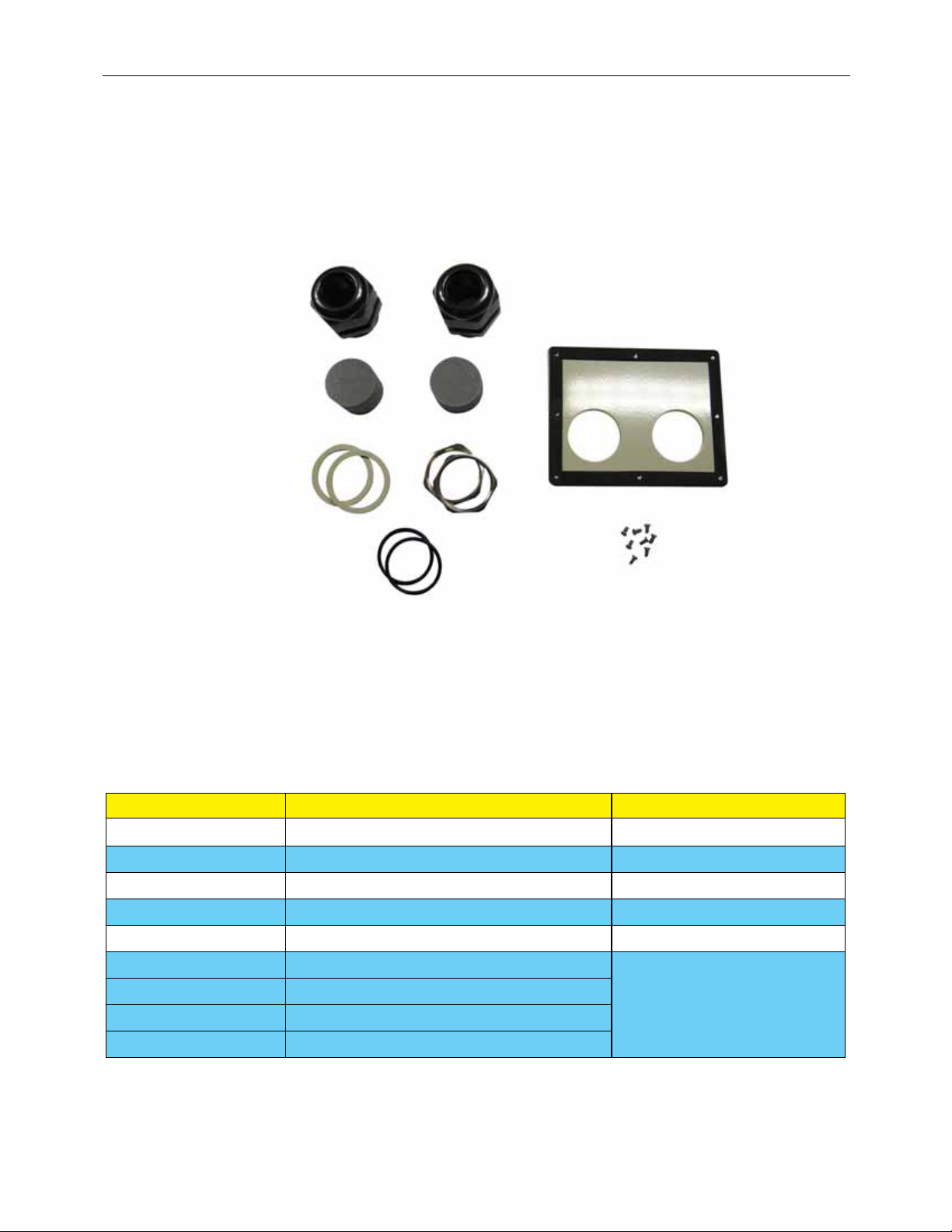
1.3 Bottom Plate Kit
A bottom plate kit (FFB-BTM-PLT-KIT) is available as a product accessory. The kit (shown in
Figure 4) contains one two-hole bottom plate, one gasket, two compression nut assemblies, and
eight mounting screws.
Figure 4. Bottom Plate Kit Components
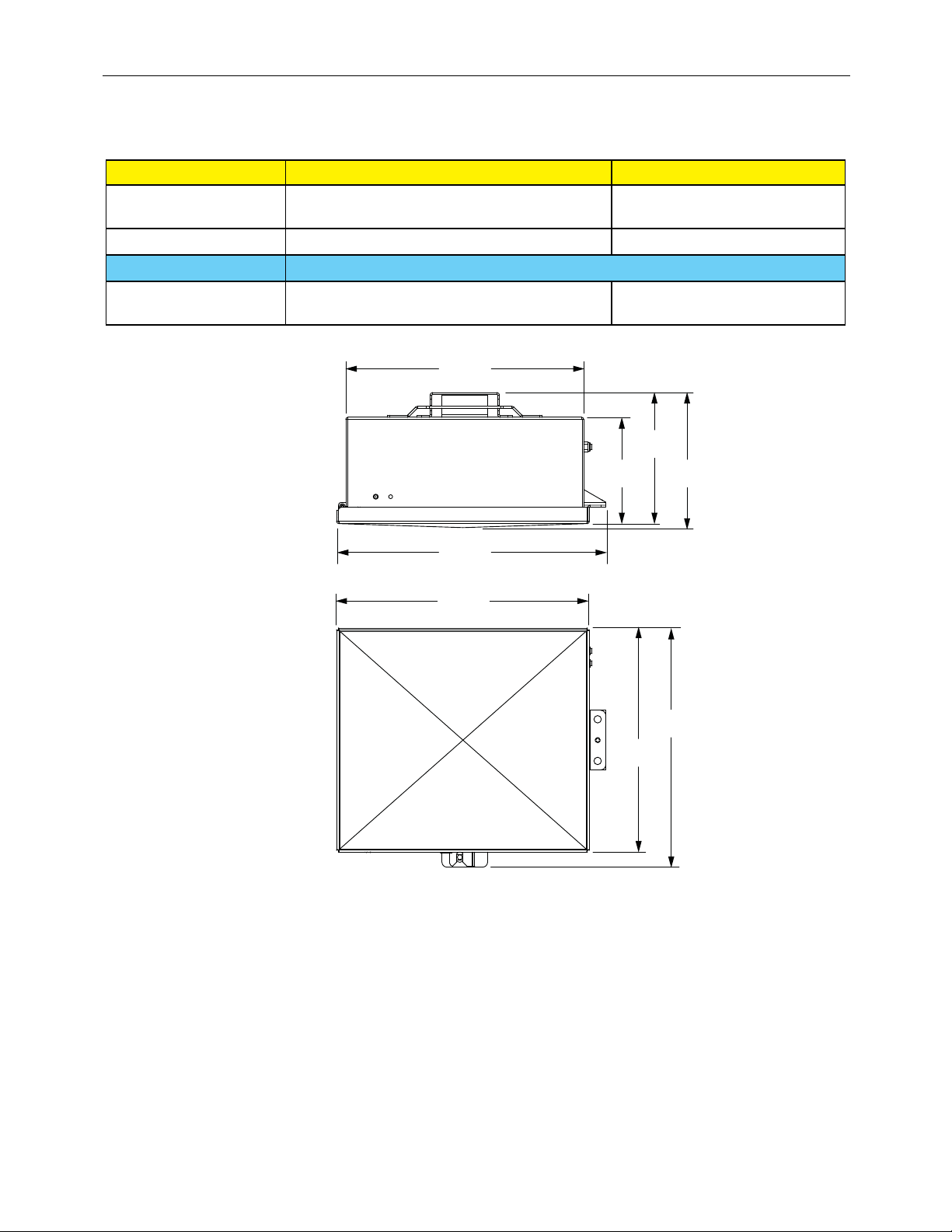
1.4 Specifications and Dimensions
Table 1 lists specifications, Figure 5 shows dimensions of the Rapid FFB.
Table 1. Specifications
ITEM SPECIFICATION COMMENTS
Dimensions (H x W x D) 11.30 x 12.74 x 5.36 in (38.70 x 32.36 x 13.61 cm)
Weight 11.50 lbs. (5.22 kg.)
Construction Aluminum 0.080 inch (.020 cm) thick
Color Putty white
Fiber count 12 or 24 fibers
Feeder cable types 100-foot, 24-fiber, MPO terminated Outside diameter:
200-foot, 12-fiber, MPO terminated
100-foot, 12-fiber, stub
200-foot, 24-fiber, stub
Basic box. See Figure 5
3.6 mm (single-mode)
3.8 mm (multimode)
Page 6
© 2017 CommScope. All Rights Reserved.
Page 7
TECP-96-614 • Issue 3 • November 2016
Table 1. Specifications, continued
ITEM SPECIFICATION COMMENTS
Drop cable termination Sliding adapter packs SC and LC; supports up to four
APL series modular adapter packs
Splice trays Up to two 12-fiber cables
Feeder cable portal Shipped with feeder cable already threaded through portal
Drop cable portals Two portals, can be used with up to 5 mm diame-
ter cables depending on configuration
12.00 IN.
(30.5 CM)
TOP VIEW
13.57 IN.
(34.5 CM)
12.74 IN.
(32.4 CM)
FRONT VIEW
Multiple cables may enter through
same portal
6.60 IN.
(16.8 CM)
5.36 IN.
(13.6 CM)
11.30 IN.
(28.7 CM)
6.80 IN.
(17.3 CM)
12.06 IN.
(30.6 CM)
2 MOUNTING THE RAPID FFB
The Rapid FFB can be mounted on a wooden utility pole, metal utility pole, wood-framed wall,
H-frame, or masonry wall. Use whichever procedure is appropriate for the application.
24653-A
Figure 5. Rapid FFB Dimensions
Page 7
© 2017 CommScope. All Rights Reserved.
Page 8

TECP-96-614 • Issue 3 • November 2016
2.1 General Recommendations
The site chosen for the installation must conform to all local codes and any permits required
must be obtained prior to the start of installation. The location must be accessible and provide
adequate parking for worker and vehicle safety. In addition, the installed FFB must not create a
visual or physical obstruction to vehicular or pedestrian traffic. Sufficient space must be
provided on all sides to facilitate FFB installation and maintenance.
Install a grounding system (not provided) that meets all local electrical codes. Check local codes
for grounding system installation, use of clamps, wire size, and any other grounding
requirements. Typically, a 2-hole grounding lug crimped to a #6 AWG solid copper wire is used
to connect the FFB to a approved earth ground source as specified by local code or practice.
2.2 Wooden Utility Pole Mounting Procedure
Use the following procedure to mount the FFB on a wooden utility pole.
1. Obtain the following fasteners and tools:
• 3/8-inch x 2 inch lag screw suitable for exterior application
• Drill
• 9/32-inch drill bit
• 1/2-inch drill bit (optional depending on pole condition)
• 9/16-inch wrench
• 216B key tool (accessory)
The following fasteners are optional depending on the condition of the pole:
• 1/2-inch threaded rod (1), 1/2-inch nut (1), 1/2-inch flat washer (2),
1/2-inch lock washer (2)
2. Using the mounting bracket as a guide, mark the location of the bracket mounting holes on
the pole as shown in
Figure 6.
3. Drill a 9/32-inch hole in the pole at each of the locations marked in step 2.
4. Secure the mounting bracket to the pole using the two 3/8-inch x 2-inch lag screws.
Tighten lag screws securely.
Page 8
© 2017 CommScope. All Rights Reserved.
Page 9

3/8-INCH X 2-INCH
LAG SCREW (2)
TECP-96-614 • Issue 3 • November 2016
FASTENERS USED TO
SECURE BRACKET TO
WOODEN UTILITY POLE
WOODEN
UTILITY POLE
MOUNTING
BRACKET
24219-A
Figure 6. Installing Mounting Bracket on a Wooden Utility Pole
Note: If the utility pole is in poor condition, install a 1/2-inch threaded rod or through-bolt
in addition to the lag screws to provide additional support in mounting the bracket to the
pole, as shown in
THREADED ROD
INSTALLATION
1/2-INCH LOCK
WASHER
1/2-INCH
NUT
Figure 7.
THREADED ROD
1/2-INCH FLAT
WASHER
1/2-INCH
1/2-INCH FLAT
WASHER
1/2-INCH FLAT
WASHER
24220-A
1/2-INCH LOCK
WASHER
1/2-INCH FLAT
WASHER
1/2-INCH
NUT
1/2-INCH
NUT
1/2-INCH
THROUGH-BOLT
THROUGH-BOLT
INSTALLATION
Figure 7. Threaded Rod or Through-Bolt Installation
© 2017 CommScope. All Rights Reserved.
Page 9
Page 10

TECP-96-614 • Issue 3 • November 2016
5. Using appropriate lifting equipment, hoist the FFB into position for attachment to the
mounting bracket.
Danger: Do not stand directly under the FFB as it is being hoisted into position for mounting. A
failure of the lifting equipment could result in serious personal injury.
6. Hang the FFB from the installed mounting bracket. The welded bracket on the back of the
FFB, shown in
partially installed cap screw at the bottom of the mounting bracket fits into the slotted tab
at the bottom of the FFB.
7. Tighten the partially installed cap screw at the bottom of the FFB using the 216B key tool.
Note: A cup washer is included with the cap screw to provide tamper resistance.
Figure 8, fits into the two slots at the top of the mounting bracket. The
WELDED
BRACKET
CAP SCREW
WITH CUP
WASHER
Figure 8. Installing FFB on Pole-Mounted Bracket
2.3 Metal Utility Pole Mounting Procedure
Use the following procedure to mount the FFB on a metal utility pole.
1. Obtain the following materials and tools:
Page 10
© 2017 CommScope. All Rights Reserved.
MOUNTING
BRACKET
24633-A
Page 11

TECP-96-614 • Issue 3 • November 2016
• 5/8-inch wide 304 AISI stainless steel banding
• Panduit BT1HT tool
2. Using a section of stainless steel banding, as shown in Figure 9, secure the pole mounting
bracket on the pole, and tighten the banding using Panduit tool #BT1HT. Adjust the tool
tension setting to #7.
Note: In operating the tool, follow the instructions provided by the tool manufacturer (see
MS Strapping Tool Operation Instructions PA24808A01).
3. Secure the bottom of the bracket to the pole by installing the cap screw with cup washer, as
shown in
Figure 9.
4. Locate the welded bracket on back of the FFB, and hang the FFB on the pole by hanging
the welded bracket on the pole mounting bracket, as shown in
Figure 9.
WELDED
BRACKET
POLE
MOUNTING
BRACKET
CAP SCREW
WITH CUP
WASHER
24730-A
Figure 9. Installing Mounting Bracket on a Metal Utility Pole
MOUNTING
SLOTS
STAINLESS
STEEL
BANDI NG
2.4 Wood-Framed Wall Mounting Procedure
Use the following procedure to mount the FFB on a wood-framed wall. If mounting the FFB on
an H-frame, follow the same basic steps except use the appropriately sized bolts with washers
and nuts in place of the wood screws in step 3.
© 2017 CommScope. All Rights Reserved.
Page 11
Page 12

TECP-96-614 • Issue 3 • November 2016
Warning: Use appropriate lifting equipment when moving or installing the FFB. Do not stand
under the FFB as it is being hoisted into position for installation. A failure of the lifting
equipment could result in serious personal injury.
1. Mount a plywood backer (not provided) on the wall in the location where the FFB will be
mounted as shown in
secure the backer to at least two (minimum) of the wall’s interior 2x4 studs.
FASTENERS USED TO
SECURE BRACKET TO
BACKER BOARD
#10 FLAT
WASHER (4)
#10 X 1-1/2 INCH
WOOD SCREW (4)
Figure 10. Use whatever tools and fasteners are required to firmly
3/4-INCH PLYWOOD
3/4-INCH PLYWOOD
BACKER BOARD
BACKER BOARD
(SECURE TO WALL STUDS)
(SECURE TO WALL STUDS)
MOUNTING
BRACKET
24216-A
Figure 10. Securing Backer Board to Wall and Installing Mounting Bracket on Backer Board
Note: It is recommended that pressure-treated plywood with a minimum thickness of
0.75-inch (19.0 cm) be used as a backer board. The backer must be firmly secured to the
interior framing of the wall to avoid a hazardous condition.
2. Obtain the following fasteners and tools:
• #10 x 1-1/2-inch wood screws (4) and # flat washers (4)
Note: If mounting on an H-frame, use appropriately-sized bolts with washers and nuts in
place of the woods screws listed above.
• Drill and 3/32-inch drill bit
• Screwdriver drill bit (for wood screws)
• 216B key tool (accessory)
3. Using the mounting bracket as a guide, mark the location of the bracket mounting holes on
the wall (or H-frame).
Page 12
© 2017 CommScope. All Rights Reserved.
Page 13

TECP-96-614 • Issue 3 • November 2016
4. Drill a 3/32-inch pilot hole in the backer board at each of the locations marked in step 3.
5. Secure the mounting bracket to the plywood backer using the four #10 x 1-1/2-inch wood
screws and four #10 flat washers. Thread the wood screws into the pilot holes and tighten
securely.
Note: If mounting on an H-frame, use the appropriately-sized bolts with washers and nuts
in place of the woods screws listed above.
6. Using appropriate lifting equipment, hoist the FFB into position for attachment to the
mounting bracket.
Danger: Do not stand directly under the FFB as it is being hoisted into position for mounting. A
failure of the lifting equipment could result in serious personal injury.
7. Hang the FFB from the installed mounting bracket. The welded bracket on the back of the
FFB, shown in
Figure 11, fits into the two slots at the top of the mounting bracket. The
partially installed cap screw at the bottom of the mounting bracket fits into the slotted tab
at the bottom of the FFB.
8. Securely tighten the partially installed cap screw at the bottom of the FFB using the 216B
key tool.
Note: A cup washer is included with the cap screw to provide tamper resistance.
WELDED
BRACKET
MOUNTING
BRACKET
CAP SCREW
WITH CUP
WASHER
24634-A
Figure 11. Installing FFB on Wall-Mounted Bracket
© 2017 CommScope. All Rights Reserved.
Page 13
Page 14

TECP-96-614 • Issue 3 • November 2016
2.5 Masonry Wall Mounting Procedure
Use the following procedure to mount the FFB on a masonry wall.
Warning: Use appropriate lifting equipment when moving or installing the FFB. Do not stand
under the FFB as it is being hoisted into position for installation. A failure of the lifting
equipment could result in serious personal injury.
1. Obtain the following fasteners and tools:
• 3/8-inch concrete anchor (2)
• 3/8-inch x 1-1/2 inch hex head capscrew (2)
• 3/8-inch flat washer (2) and 3/8-inch lock washer (2)
• Drill
• 5/8-inch masonry drill bit (check hole size with concrete anchor manufacturer)
• 9/16-inch wrench
• 216B key tool (accessory)
2. Using the mounting bracket as a guide, mark the location of the bracket mounting holes on
the masonry wall as shown in
Figure 12.
Note: Locate the mounting anchors as close as possible to the center of bricks or blocks.
3/8-INCH
CONCRETE
ANCHOR (2)
MASONRY
WALL
MOUNTING
BRACKET
3/8 x 1-1/2-INCH
CAP SCREW (2)
Page 14
© 2017 CommScope. All Rights Reserved.
3/8-INCH FLAT
3/8-INCH LOCK
WASHER (2)
WASHER (2)
24218-A
Figure 12. Installing Mounting Bracket on a Masonry Wall
Page 15

TECP-96-614 • Issue 3 • November 2016
3. Drill a 5/8-inch hole (check hole size with anchor manufacturer) in the wall at each of the
locations marked in step 2.
4. Secure the mounting bracket to the masonry wall using the two 3/8-inch x 1-1/2-inch cap
screws, two 3/8-inch lock washers, and two 3/8-inch flat washers. Tighten cap screws
securely.
5. Using appropriate lifting equipment, hoist the FFB into position for attachment to the
mounting bracket.
Warning: Do not stand directly under the FFB as it is being hoisted into position for cable
installation. A failure of the lifting equipment could result in serious personal injury.
6. Hang the FFB from the installed mounting bracket. The welded bracket on the back of the
FFB (see
Figure 13) fits into the two slots at the top of the mounting bracket. The partially
installed cap screw at the bottom of the mounting bracket fits into the slotted tab at the
bottom of the FFB.
WELDED
BRACKET
MOUNTING
BRACKET
CAP SCREW
WITH CUP
WASHER
24634-A
Figure 13. Installing FFB on Wall-Mounted Bracket
7. Tighten the partially installed cap screw at the bottom of the FFB using the 216B key tool.
Note: A cup washer is included with the cap screw to provide tamper resistance.
© 2017 CommScope. All Rights Reserved.
Page 15
Page 16

TECP-96-614 • Issue 3 • November 2016
3 GROUNDING THE RAPID FFB
Use the following procedure to connect the grounding wire to the FFB.
1. Locate the grounding studs shown in Figure 14.
2. Obtain a 2-hole compression-type grounding lug with 0.625-inch hole spacing (not
provided) and a length of #6 AWG solid copper wire.
3. Crimp the 2-hole grounding lug to the copper wire using the recommended crimping tool.
4. Secure the grounding lug and attached wire (see Figure 14) to the side of the FFB. Using a
torque wrench with a 7/16-inch socket, tighten the grounding stud nuts to 40 to 45 lbsforce inches (4.5 to 5.1 Nm) of torque.
Warning: Failure to properly tighten the grounding stud nuts could result in improper
grounding of the FFB and result in performance or safety issues.
5. Route the free end of the grounding wire to an approved earth ground source.
6. Cut the grounding wire to length and connect it to the earth ground source as specified by
local code or practice.
24661-A
Figure 14. Grounding Wire Connection To FFB
NUTS
GROUND
LUG
Page 16
© 2017 CommScope. All Rights Reserved.
Page 17

4 OPENING AND CLOSING THE OUTER DOOR
The outdoor door of the FFB is locked or unlocked with a 216B key tool. The outer door swings
out on a hinge. Use the following procedure to open or close the outer door. Refer to
To open the outer door, back out the cap screw using a 216B key tool. Swing out the door until
the wind jammer locks into place.
To close the door, lift the wind jammer to disengage it and swing the door closed. Lock the door
using the 216B key tool.
TECP-96-614 • Issue 3 • November 2016
Figure 15.
CAP
SCREW
WIND
JAMMER
Figure 15. Opening and Closing the Outer Door
24703-A
© 2017 CommScope. All Rights Reserved.
Page 17
Page 18

TECP-96-614 • Issue 3 • November 2016
5 INSTALLING THE FEEDER CABLE
The Rapid FFB is shipped with the feeder cable spooled around the internal RapidReel and with
the RapidReel locked to maintain tension.
Use the following procedure to install the feeder cable.
Caution: Keep tension on the cable when paying out it out. Otherwise, the cable may loosen on
the spool.
1. Locate the termination point to which the feeder cable will be routed.
2. Loosen the feeder cable compression nut and remove the grommet as shown in Figure 16.
3. Loosen the screw on the RapidReel and rotate the spool counterclockwise to pay out the
cable as shown in
Figure 16.
LOOSEN SCREW AND
ROTATE SPOOL TO
PAY-OUT CABLE
Note: Do not pull on the connector directly. Use either the pulling swivel as described here
or wrap the lead end of the cable around your hand as described in
4. Wrap several layers of vinyl tape around the pulling swivel and trailing connector (if any)
as shown in
5. Tie a pulling cord to the swivel and guide the pulling cord into the conduit or duct as
shown in
Page 18
© 2017 CommScope. All Rights Reserved.
Figure 18 and Figure 19.
LOOSEN
COMPRESSION
NUT AND REMOVE
GROMMET
GROMMET
Figure 16. Installing the Cable Compression Fitting
Figure 17.
24696-A
Figure 20 on Page 20.
Page 19

TECP-96-614 • Issue 3 • November 2016
Figure 17. Inserting Leading Connector Pulling Eye(s) into Pulling Swivel Mesh
B
Figure 18. Wrapping Vinyl Tape Around Pulling Swivel and Trailing Connector
FFB
MOUNTING
LOCATION
OPTIONAL
CONDUIT OR DUCT
TERMINATION
LOCATION
24857-A
Figure 19. Positioning External Spool at Mounting Location
6. At the conduit exit location, remove the tape, mesh, and pulling swivel from the leading
connector pulling eye(s).
© 2017 CommScope. All Rights Reserved.
Page 19
Page 20

TECP-96-614 • Issue 3 • November 2016
Caution: If the cable will be pulled to some further location, not within reach at the time being,
make sure to use the hand-wrap method shown in Figure 20 to pull the cable to the point where
the cable will be spliced or terminated.
7. At the termination location, when the entire cable is paid out, either splice or connect the
cable as follows:
a. If splicing, cut off the non-functional connector and splice the fibers following local
practice; or
b. If connecting to MPO adapters, remove the pulling eye(s) as directed in the instruction
sheet provided with the product (ADCP-90-389) and connect the connectors to the
MPO adapters.
8. Rotate the RapidReel clockwise (if possible) to wrap some cable back onto the spool
before tightening the screw as directed in the next step.
Page 20
© 2017 CommScope. All Rights Reserved.
Figure 20. Hand-Wrap Method
Page 21

TECP-96-614 • Issue 3 • November 2016
9. Within the FFB, rotate the spool to the notch and tighten the screw as shown in Figure 21.
10. Replace the grommet on the feeder cable, just below the compression nut, and stuff the
grommet into the compression nut as also shown in
Figure 21.
ROTATE SPOOL TO
NOTCH AND
TIGHTEN SCREW
INSERT GROMMET
AND TIGHTEN
COMPRESSION
NUT
GROMMET
24697-A
Figure 21. Securing the Feeder Cable
11. Tighten the compression nut to secure the cable in the compression nut assembly.
© 2017 CommScope. All Rights Reserved.
Page 21
Page 22

TECP-96-614 • Issue 3 • November 2016
6 INSTALLING A DROP CABLE
Use the following procedure to install a drop cable.
1. Locate the compression nut assemblies that were shipped with the FFB. They are in a
separate package.
2. Assemble the retaining nut, O-ring, compressing fitting base, metal spacer, grommet, and
compression nut on the FFB as shown in
Figure 22.
RETAINING
NUT
O-RING
COMPRESSION
FITTING BASE
METAL
SPACER
COMPRESSION
NUT
24791-A
Figure 22. Installing the Compression Nut Assembly
3. Thread the drop cable through the compression assembly into the FFB through the hole in
the compression nut assembly.
4. Route the drop cable to its destination.
5. Place the grommet on the cable just below the compression nut and stuff the grommet into
the compression nut as shown in
Figure 23. Tighten the nut.
6. Secure the drop cable inside the FFB using the mille-tie provided. Fasten the mille-tie to
the cable lance in the location shown in
Figure 23.
Page 22
© 2017 CommScope. All Rights Reserved.
Page 23

TECP-96-614 • Issue 3 • November 2016
MILLE-TIE
24698-A
7 CLEANING CONNECTORS AND ADAPTERS
Connectors and adapters should be carefully cleaned whenever connecting or disconnecting a
fiber optic cable or patch cord.
Refer to the Optical Fiber Systems Cleaning and Mating Instructions (ADCP-90-159) provided
with CommScope patch cords and optical cable assemblies for the connector and adapter
cleaning procedures.
INSERT GROMMET
AND TIGHTEN
COMPRESSION
NUT
GROMMET
© 2017 CommScope. All Rights Reserved.
Page 23
Page 24

TECP-96-614 • Issue 3 • November 2016
8 ACCESSING ADAPTER PACKS
1. Lift up the small tab on top of the adapter pack.
2. Lift up the adapter pack to the position shown in Figure 23.
TAB
9 PERFORMING A SPLICE
If installing a stub-ended drop cable, perform the following procedure to remove the splice trays
from the FFB and splice the drop fibers to the feeder fibers.
1. Follow the instructions in Topic 6 on Page 22 to install the drop cable until you get to the
step referring to this procedure for splicing.
2. Unstrap the hook-and-loop strap holding the splice trays and lift the splice tray out of the
box unto a flat surface as shown in
cable wound back into the FFB should be of approximately equal lengths.
3. Route the feeder pigtail fibers into the splice try as shown in Figure 25. Wind about 36
inches (91.4 cm) around within the tray, as indicated.
4. Complete the splicing procedures following local practice.
5. Return the splice tray to the box and secure the splice tray using the hook-and-loop strap.
ADAPTER
PAC K
24787-A
Figure 23. Accessing an Adapter Pack
Figure 24. Note that the lengths of feeder and drop
6. Complete the instructions in Topic 6 on Page 22 to replace the grommet on the cable and
secure the grommet and cable in the compression nut.
Page 24
© 2017 CommScope. All Rights Reserved.
Page 25

NOTE: FEEDER AND
DROP CABLE LENGTHS
WOUND INTO CABINET
SHOULD BE EQUAL.
TECP-96-614 • Issue 3 • November 2016
DROP
CABLE
FEEDER
CABLE
Figure 24. Positioning Splice Tray for Splicing
FOLD BACK
ARAMID YARN
FEEDER
CABLE
INTERNAL
PIGTAIL
CABLE
TIE-DOWN
POINTS
SPLICE
CHIP
Figure 25. Routing Feeder Fibers on Splice Tray
SPLICE
CHIP
24700-B
APPROX.
TOTAL WIND
36 IN.
(91.4 CM)
24671-A
© 2017 CommScope. All Rights Reserved.
Page 25
Page 26

TECP-96-614 • Issue 3 • November 2016
10 PRODUCT SUPPORT
http://www.commscope.com/SupportCenter
Page 26
 Loading...