

Page 1
ADCP-92-098
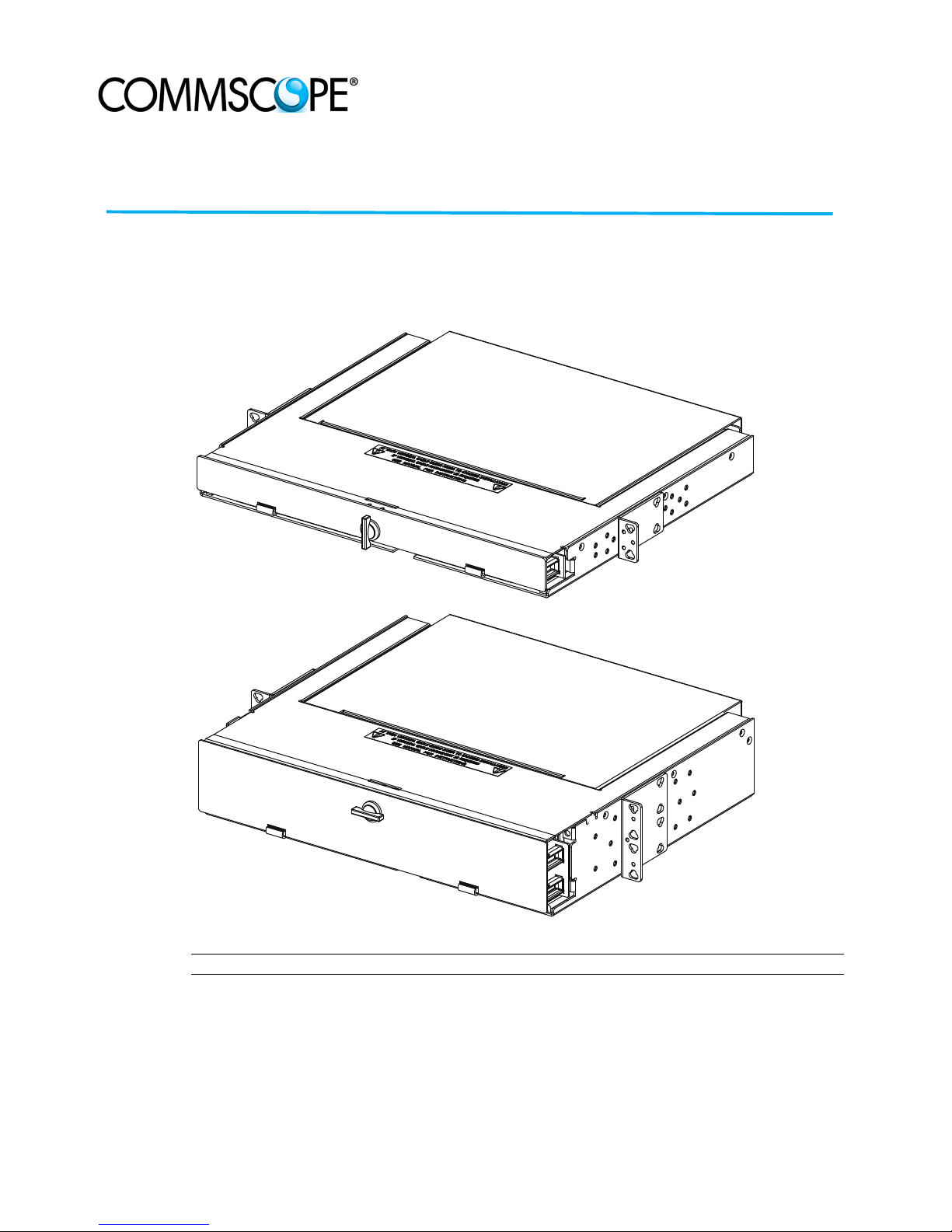
1U PANEL
2U PANEL
23967-B
Rev. C, May 2018
commscope.com
User
Manual
FPX Series
1U & 2U Fiber Panel
Content Page
INTRODUCTION . . . . . . . . . . . . . . . . . . . . . . . . . . . . . . . . . . . . . . . . . . . . . . . . . . . . . . . . . . . . . . . . . . . . . . . . . . . . . .2
Related Publications . . . . . . . . . . . . . . . . . . . . . . . . . . . . . . . . . . . . . . . . . . . . . . . . . . . . . . . . . . . . . . . . . . . . .2
Trademark Information . . . . . . . . . . . . . . . . . . . . . . . . . . . . . . . . . . . . . . . . . . . . . . . . . . . . . . . . . . . . . . . . . . . .2
Admonishments . . . . . . . . . . . . . . . . . . . . . . . . . . . . . . . . . . . . . . . . . . . . . . . . . . . . . . . . . . . . . . . . . . . . . . . . .3
1 DESCRIPTION . . . . . . . . . . . . . . . . . . . . . . . . . . . . . . . . . . . . . . . . . . . . . . . . . . . . . . . . . . . . . . . . . . . . . . . . . .3
2 INSTALLATION. . . . . . . . . . . . . . . . . . . . . . . . . . . . . . . . . . . . . . . . . . . . . . . . . . . . . . . . . . . . . . . . . . . . . . . . . .5
ADCP-92-098 Rev C Page 1
www.commscope.com © 2018 CommScope. All Rights Reserved.
(continued)
Page 2

ADCP-92-098 • Rev C • May 2018
Content (continued) Page
2.1 Selecting a Mounting Bracket Option . . . . . . . . . . . . . . . . . . . . . . . . . . . . . . . . . . . . . . . . . . . . . . . . . . . . 6
2.2 Installing the Panel on the Rack . . . . . . . . . . . . . . . . . . . . . . . . . . . . . . . . . . . . . . . . . . . . . . . . . . . . . . . 7
2.3 Installing Vertical Cable Guides (VCGs) . . . . . . . . . . . . . . . . . . . . . . . . . . . . . . . . . . . . . . . . . . . . . . . . . . 8
2.4 Sliding the Drawer In and Out . . . . . . . . . . . . . . . . . . . . . . . . . . . . . . . . . . . . . . . . . . . . . . . . . . . . . . . . . 9
2.5 Panel Grounding . . . . . . . . . . . . . . . . . . . . . . . . . . . . . . . . . . . . . . . . . . . . . . . . . . . . . . . . . . . . . . . . . 11
2.6 Installing Adapter Packs. . . . . . . . . . . . . . . . . . . . . . . . . . . . . . . . . . . . . . . . . . . . . . . . . . . . . . . . . . . . 12
2.7 Installing MPO Cassettes . . . . . . . . . . . . . . . . . . . . . . . . . . . . . . . . . . . . . . . . . . . . . . . . . . . . . . . . . . . 13
2.8 Termination Only Installation . . . . . . . . . . . . . . . . . . . . . . . . . . . . . . . . . . . . . . . . . . . . . . . . . . . . . . . . 14
3 CABLE CLAMP INSTALLATION . . . . . . . . . . . . . . . . . . . . . . . . . . . . . . . . . . . . . . . . . . . . . . . . . . . . . . . . . . . . . 15
3.1 Installing a Cable Clamp for OSP Cable . . . . . . . . . . . . . . . . . . . . . . . . . . . . . . . . . . . . . . . . . . . . . . . . . 15
3.2 Installing a Cable Clamp for MPO Trunk Cable . . . . . . . . . . . . . . . . . . . . . . . . . . . . . . . . . . . . . . . . . . . . 16
4 CABLE ROUTING PROCEDURES . . . . . . . . . . . . . . . . . . . . . . . . . . . . . . . . . . . . . . . . . . . . . . . . . . . . . . . . . . . . 17
4.1 Termination and Splice Panel Procedures . . . . . . . . . . . . . . . . . . . . . . . . . . . . . . . . . . . . . . . . . . . . . . . 17
4.2 Termination Only Panel Procedures . . . . . . . . . . . . . . . . . . . . . . . . . . . . . . . . . . . . . . . . . . . . . . . . . . . . 22
4.3 MPO Termination Only Panel Procedures . . . . . . . . . . . . . . . . . . . . . . . . . . . . . . . . . . . . . . . . . . . . . . . . 26
5 CONTACT INFORMATION . . . . . . . . . . . . . . . . . . . . . . . . . . . . . . . . . . . . . . . . . . . . . . . . . . . . . . . . . . . . . . . . . 28
4.1.1 Routing Pigtails . . . . . . . . . . . . . . . . . . . . . . . . . . . . . . . . . . . . . . . . . . . . . . . . . . . . . . . . . . 17
4.1.2 Routing OSP Cable, Right Side Entry . . . . . . . . . . . . . . . . . . . . . . . . . . . . . . . . . . . . . . . . . . . . 18
4.1.3 Routing OSP Cable, Left Side Entry . . . . . . . . . . . . . . . . . . . . . . . . . . . . . . . . . . . . . . . . . . . . . 20
4.1.4 Routing Pigtails and OSP Fibers in Splice Tray . . . . . . . . . . . . . . . . . . . . . . . . . . . . . . . . . . . . . 21
4.2.1 Routing OSP Cable, Right Side Entry (Adapter Packs) . . . . . . . . . . . . . . . . . . . . . . . . . . . . . . . . 22
4.2.2 Routing OSP Cable, Left Side Entry (Adapter Cassettes) . . . . . . . . . . . . . . . . . . . . . . . . . . . . . . . 23
4.2.3 Routing OSP Cable, Left Side Entry (MPO Cassettes) . . . . . . . . . . . . . . . . . . . . . . . . . . . . . . . . . 24
4.2.4 Routing OSP Cable, Right Side Entry (MPO cassettes) . . . . . . . . . . . . . . . . . . . . . . . . . . . . . . . . 25
4.3.1 Routing MPO Trunk Cable, Right Side Entry (MPO Adapter Packs) . . . . . . . . . . . . . . . . . . . . . . . . 26
4.3.2 Routing MPO Trunk Cable, Left Side Entry (MPO Adapter Packs) . . . . . . . . . . . . . . . . . . . . . . . . . 27
INTRODUCTION
This manual contains descriptions and installation and cable routing instructions for the TE
Connectivity FPX 1U and 2U Fiber Panels.
Related Publications
Title/Description ADCP Number
FPX MPO Trunk Cable Clamp Kit Instructions 92-080
Trademark Information
CommScope (logo0 and CommScope are trademarks,
Page 2
© 2018 CommScope. All Rights Reserved.
Page 3

Admonishments
REMOVABLE REAR
COVER PROVIDES
EASY ACCESS FOR
CABLE ROUTING
AND MANAGEMENT
RADIUS LIMITERS FOR
CABLE MANAGEMENT (8)
CABLE CLIP
(1 PER SIDE)
HINGED
FRONT
COVER
DESIGNATION
LABEL (2)
COVER
LATCH
BULKHEAD
ACCOMMODATES
ADAPTER PACKS OR
MPO CASSETTES
OSP CABLE ENTRY
(EITHER SIDE)
SLIDING
TRAY
MOUNTING
BRACKET (2)
23970-A
SPLICE TRAY
LOCATION
TRAY RETAINING
CLIPS (2 PER SIDE)
Important safety admonishments are used throughout this manual to warn of possible hazards to
persons or equipment. These warnings are flagged by use of the triangular alert icon (seen
below) and are listed in descending order of severity of injury or damage and likelihood of
occurrence.
Danger: Danger is used to indicate the presence of a hazard that will cause severe personal
injury, death, or substantial property damage if the hazard is not avoided.
Warning: Warning is used to indicate the presence of a hazard that can cause severe personal
injury, death, or substantial property damage if the hazard is not avoided.
Caution: Caution is used to indicate the presence of a hazard that will or can cause minor
personal injury or property damage if the hazard is not avoided.
1 DESCRIPTION
ADCP-92-098 • Rev C • May 2018
The FPX 1U and 2U Panels can accommodate up to 48 and 96 terminations, respectively. The
FPX 1U and 2U Panels can be configured for termination and splice or termination only
(without splice trays).
Note: The Fiber Panel Next Generation is designed to be installed in an environmentally
controlled network telecommunications facility such as a Central Office, Controlled
Environmental Vault, or Data Center.
Figure 1 shows the external features of a typical 1U panel.
Figure 1. FPX 1U Panel External Features
© 2018 CommScope. All Rights Reserved.
Page 3
Page 4
ADCP-92-098 • Rev C • May 2018
Typically, these panels ship empty (without adapter packs, MPO cassettes, splice trays, or
pigtails), but they may also be ordered with any of these components already installed.The panel
accommodates adapter packs and MPO cassettes.
Caution: Adapter packs and MPO cassettes should not be both used in the same panel.
The panel may be ordered loaded with adapter packs only, or loaded with both adapter packs
and pre-terminated, factory-installed cable. While not recommended, field-installed connectors
can be accommodated.
The panel may be used in either single mode or multimode applications, and with either
stranded or ribbon cable. Cables can be either Intrafacility Fiber (IFC) or Outside Plant (OSP).
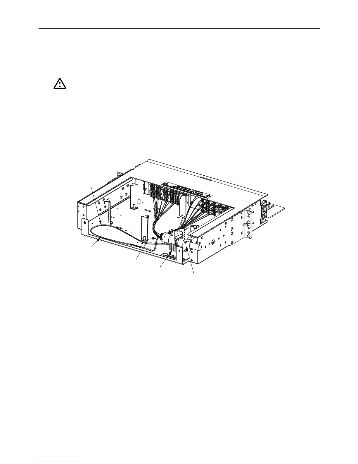
Figure 2 shows a 2U panel.
INDIVIDUAL
SUBUNIT
PROTECTIVE
TUBES
CABLE
BREAKOUT
FANOUT
CHIPS
CABLE
CLAMP
Figure 2. FPX 2U Panel with Termination Only (Rear View)
24620-A
Page 4
© 2018 CommScope. All Rights Reserved.
Page 5
ADCP-92-098 • Rev C • May 2018
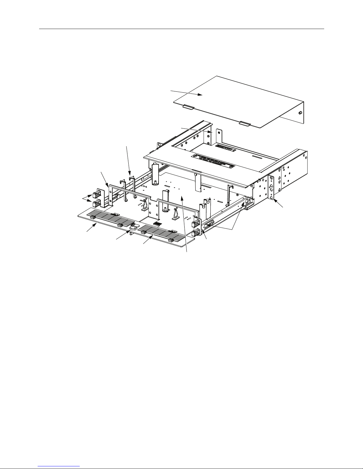
REMOVABLE REAR
COVER PROVIDES
EASY ACCESS FOR
CABLE ROUTING
AND MANAGEMENT
RADIUS LIMITERS FOR
CABLE MANAGEMENT (8)
HINGED
FRONT
COVER
DESIGNATION
LABEL (2)
COVER
LATCH
BULKHEAD
ACCOMMODATES
ADAPTER PACKS OR
MPO CASSETTES
OSP CABLE ENTRY
(EITHER SIDE)
MOUNTING
BRACKET (2)
24621-A
SPLICE
TRAY LOCATION
CABLE CLIP
(2 PER SIDE)
SLIDING
TRAY
TRAY RETAINING
CLIPS (2 PER SIDE)
The 1U termination and splice panel has one splice tray. The 2U termination and splice panel
has two splice trays.
Figure 3 shows the external features of a 2U panel.
2 INSTALLATION
Installation of a FPX panel involves the following tasks:
1. Selecting the mounting brackets (covered in Section 2.1 on Page 6);
2. Installing the panel on the rack (covered in Section 2.2 on Page 7);
3. (Optional) Installing vertical cable guides (covered in Section 2.3 on Page 8);
4. (Optional) Installing adapter packs (covered in Section 2.6 on Page 12);
5. (Optional) Installing MPO cassettes (covered in Section 2.7 on Page 13);
6. Termination Only Installation (covered in Section 2.8 on Page 14)
7. Installing a cable clamp (covered in Section 3 on Page 15);
8. Routing cables and pigtails (covered in Section 4 on Page 17).
Figure 3. FPX 2U Panel External Features
Page 5
© 2018 CommScope. All Rights Reserved.
Page 6
ADCP-92-098 • Rev C • May 2018
23968-B
1U FIBER PANEL
2U FIBER PANEL
5 INCH RACK RECESS
POSITION (AS SHIPPED)
5 INCH RACK RECESS
POSITION (AS SHIPPED)
ROTATE BRACKET
FOR 23-INCH
RACK MOUNTING
ROTATE BRACKET
FOR 23-INCH
RACK MOUNTING
Warning: Never install equipment in a wet location or during a lightning storm. When
installing or modifying communication lines, disconnect lines at the network interface before
working with uninsulated lines or terminals.
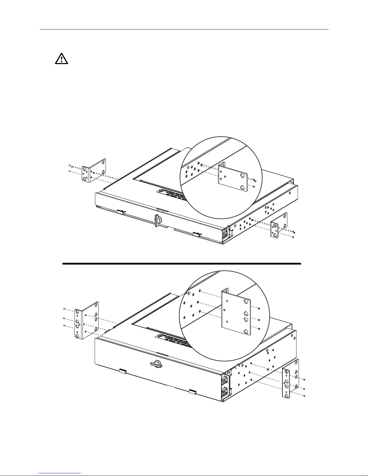
2.1 Selecting a Mounting Bracket Option
The 1U and 2U panels are shipped with mounting brackets configured for a 19-inch EIA/
WECO rack with a 5-inch recess. The mounting brackets can also be reconfigured for a 4-inch
rack recess.
Figure 4 shows the available mounting options for both panels.
Page 6
© 2018 CommScope. All Rights Reserved.
Figure 4. Selecting a Mounting Bracket Option
Page 7
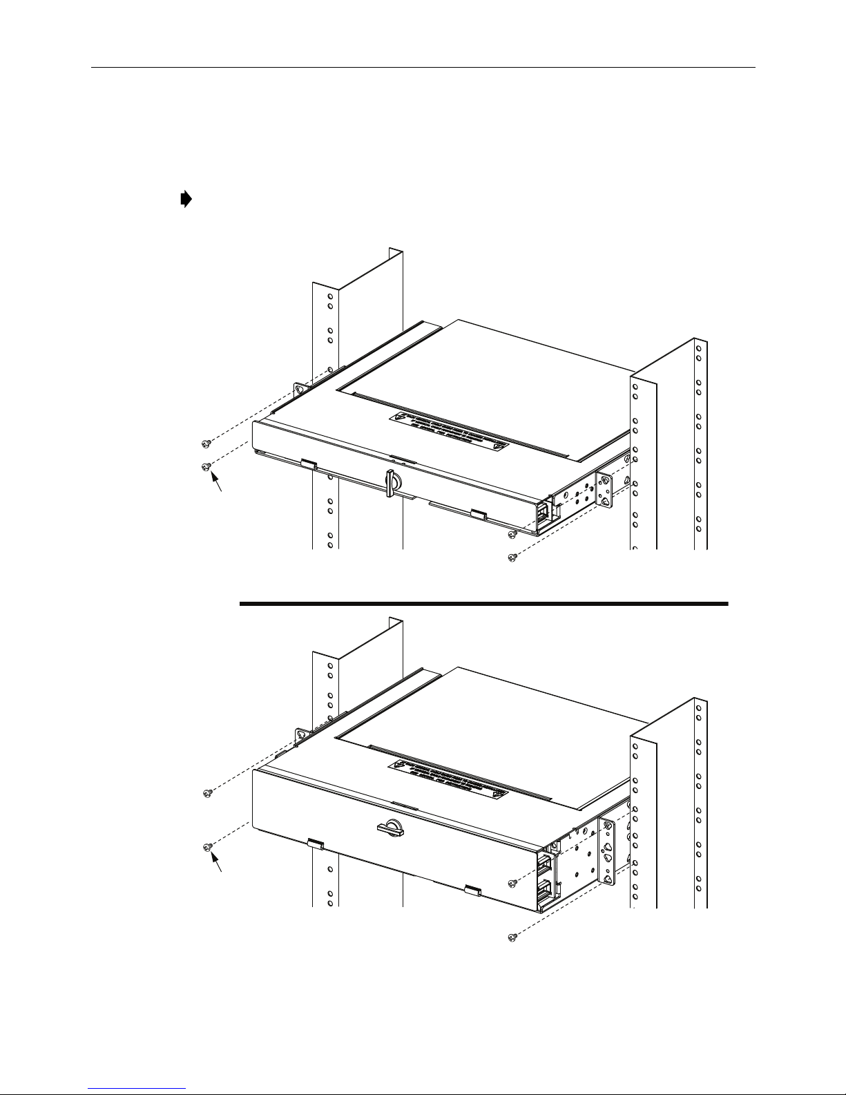
2.2 Installing the Panel on the Rack
12-24 SCREWS
(4 PLACES)
12-24 SCREWS
(4 PLACES)
23971-B
Using 12-24 screws, secure the panel on the rack as shown in Figure 5.
Note: Figure 5 shows the 1U and 2U fiber panels installed in a 19-inch rack with a 5-inch
recess.
ADCP-92-098 • Rev C • May 2018
Figure 5. Installing the Panel on the Rack
Page 7
© 2018 CommScope. All Rights Reserved.
Page 8
ADCP-92-098 • Rev C • May 2018
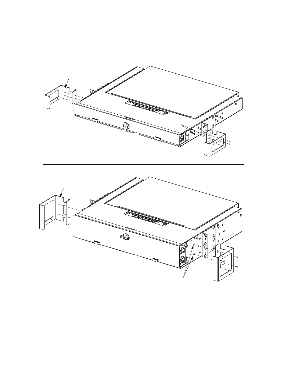
INSTALLATION
HOLES FOR VCG
6-32 SCREWS
(2 PER VCG)
(PROVIDED)
6-32 SCREWS
(2 PER VCG)
(PROVIDED)
1U FIBER PANEL
2U FIBER PANEL
VCG (2)
VCG (2)
INSTALLATION
HOLES FOR VCG
23972-B
2.3 Installing Vertical Cable Guides (VCGs)
Install the VCGs (one per side) as shown in Figure 6.
Page 8
© 2018 CommScope. All Rights Reserved.
Figure 6. Installing Vertical Cable Guides
Page 9
2.4 Sliding the Drawer In and Out
The panel has a tray release button and tray retainer clips designed to ensure that the drawer is
opened carefully and remains open until work in the drawer is competed. These items look the
same and operate the same on the 1U and 2U panels.
Use the following procedure to slide the drawer in and out (2U shown):
1. To release a closed drawer, press the release button down, as shown in Figure 7, and slide
the drawer out to the first detent.
ADCP-92-098 • Rev C • May 2018
PRESS BUTTON DOWN
TO PULL TRAY OUT
TO FIRST DETENT
Figure 7. Releasing Closed Drawer to Open It
23944-B
© 2018 CommScope. All Rights Reserved.
Page 9
Page 10

ADCP-92-098 • Rev C • May 2018
PRESS IN TRAY RETAINER
CLIPS (ONE ON EACH SIDE)
TO FULLY EXTEND TRAY
23945-B
PRESS IN TRAY RETAINER
CLIPS (ONE ON EACH SIDE)
TO SLIDE TRAY BACK
INTO PLACE
23946-B
2. To free the drawer to open it fully, press in the retainer clips (one on each side) located as
shown in
Figure 8. Slide the drawer out until it locks into place.
Figure 8. Freeing Drawer to Slide It Out Fully
3. To release an open drawer to close it, release the retainer clips (one on each side) located
as shown in
Figure 9. Slide the drawer in until it locks into the closed position.
Page 10
© 2018 CommScope. All Rights Reserved.
Figure 9. Releasing Open Drawer to Close It
Page 11

2.5 Panel Grounding
24016-A
2-HOLE LUG
TERMINAL
COPPER WIRE
STRIP BACK INSULATION
PER LUG MANUFACTURER'S
RECOMMENDATION
HOLE CENTER
SPACING:
0.625 INCHES
Each panel has a grounding location marked with the standard grounding symbol. This location
is on the right side of the panel (see
provided to attach a 2-hole lug terminal at the grounding location, as shown in Figure 11.
Follow local practice.
Note: Ground the unit to the local facility CBN (Common Bonding Network) or IBN
(Isolated Bonding Network) per local practice.
ADCP-92-098 • Rev C • May 2018
Figure 10). Use the two 10-32 screws and star washers
Figure 10. Grounding Location
(Rear View of Panel)
23947-B
GROUNDING
LOCATION
Figure 11. Ground Stud
Page 11
© 2018 CommScope. All Rights Reserved.
Page 12

ADCP-92-098 • Rev C • May 2018
INSTALL ADAPTER PACKS
IN ORIENTATION SHOWN
INSTALL RIGHT SIDE ADAPTER PACKS
WITH ADAPTERS ANGLED TOWARDTHE RIGHT
NYLATCH PLUNGER FASTENERS MUST BE
PULLED OUT BEFORE INSERTING THE
ADAPTER PACK INTO MOUNTING HOLES
IN PANEL
AFTER INSTALLING ADAPTER PACK,
PUSH NYLATCH PLUNGER FASTENERS
"IN" TO LOCK ADAPTER PACK INTO PANEL
"OUT"
POSITION
"IN"
POSITION
24622-A
INSTALL LEFT SIDE ADAPTER
PACKS WITH ADAPTERS ANGLED
TOWARD THE LEFT
2.6 Installing Adapter Packs
The 1U panel accommodates two adapter packs. The 2U accommodates four adapter packs.
Adapter packs are installed in the same manner for both 1U and 2U panels. Adapter packs
installed on left side of panel are angled left while adapter packs installed on right side are
angled right. Install the adapter packs as shown in
Figure 12 (2U shown).
Page 12
© 2018 CommScope. All Rights Reserved.
Figure 12. Installing Adapter Packs
Page 13

2.7 Installing MPO Cassettes
The 1U panel accommodates two MPO cassettes, the 2U accommodates four. The procedure for
the 1U and 2U is the same. To install or remove an MPO cassette, pull the Nylatch plunger
fastener out, orienting the MPO as shown in
Caution: Adapter packs and MPO cassettes should not be both used in the same panel.
INSTALL LEFT SIDE MPO
CASSETTES WITH ADAPTERS
ANGLED TOWARD THE LEFT
Figure 13.
INSTALL MPO CASSETTES
IN ORIENTATION SHOWN
ADCP-92-098 • Rev C • May 2018
"OUT"
POSITION
NYLATCH PLUNGER FASTENERS MUST BE
PULLED OUT BEFORE INSERTING THE
MPO CASSETTE INTO MOUNTING HOLES
IN PANEL
INSTALL RIGHT SIDE MPO
CASSETTES WITH ADAPTERS
ANGLED TOWARD THE RIGHT
AFTER INSTALLING MPO CASSETTE,
PUSH NYLATCH PLUNGER FASTENERS
"IN" TO LOCK CASSETTE INTO PANEL
"IN"
POSITION
23948-B
Figure 13. Installing MPO Cassettes
Page 13
© 2018 CommScope. All Rights Reserved.
Page 14

ADCP-92-098 • Rev C • May 2018
INDIVIDUAL
SUBUNIT
PROTECTIVE
TUBES
CABLE
BREAKOUT
FANOUT
CHIPS
RIGHT
ENTRY
LEFT
ENTRY
CABLE
CLAMP
24623-A
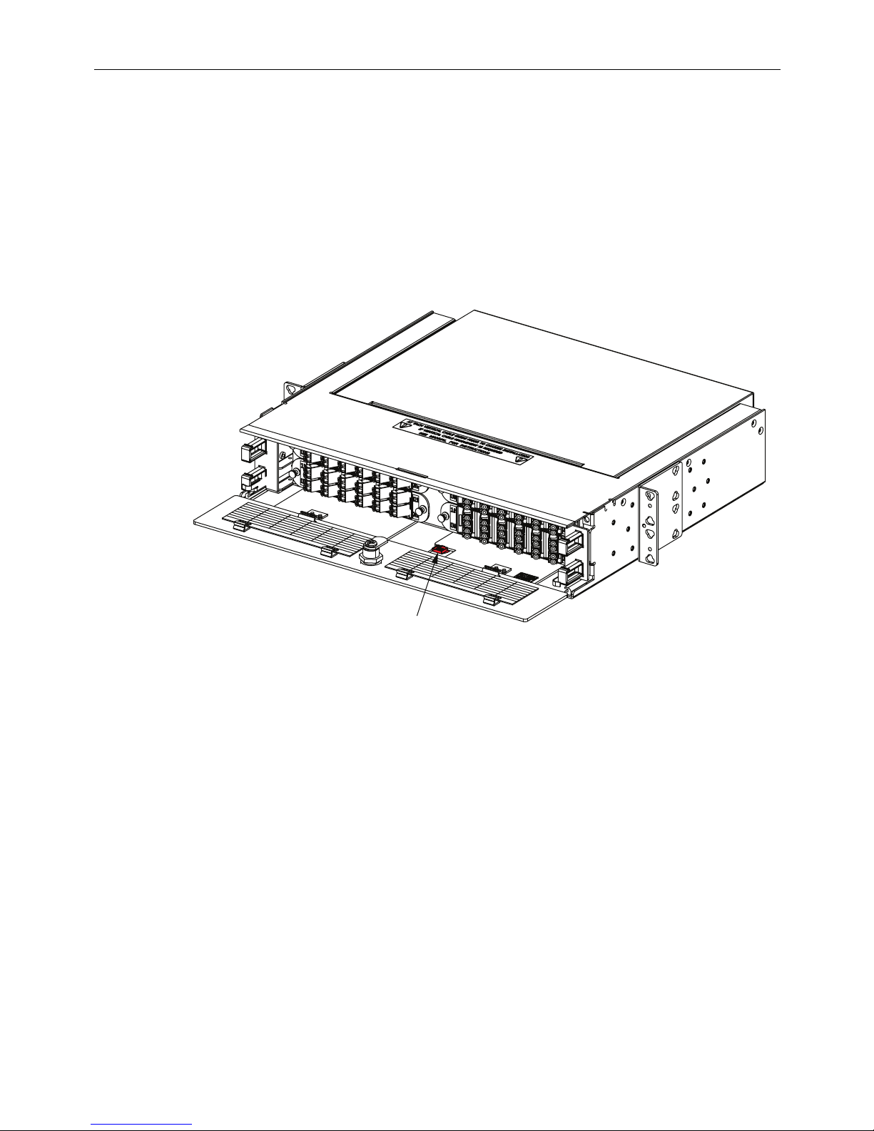
2.8 Termination Only Installation
Install cable after panel is mounted in the equipment rack, as described in
Section 2.2
. Installation
consists of routing cable to the panel, stripping back outside cable sheath exposing the optical
fibers, installing a cable clamp to secure cable to the panel, and routing fibers to the splice tray. If
cable has a metallic strength member it must be grounded following local practices.
Two clamps are provided since two cables may be installed on a single panel. Each clamp can
accommodate one cable with an outside diameter of 0.2 to 0.7 inches (0.51 to 1.78 cm). Refer to
Section 3.1 for clamp installation. Typically, only one cable is installed per panel. the cable
clamp may be installed on either side.
Allow a fiber service loop of at least 96-inches (2.5 meters) when stripping the cable sheath. This
provides sufficient length for routing the buffer tubes within the panel and for splicing. After
entry, the buffer tubes are routed to the splice tray. Splice tray mounts on the bottom of the panel.
Use the following procedure to secure the IFC/OSP cable at the fiber entry point and to route the
optical fibers into the panel:
1. Route the IFC/OSP cable to the selected entry opening at the side of the panel.
Note: Cables may enter the panel from either the left or right and may be clamped to
either the left or right side. For cable mounting locations see
Figure 14.
Figure 14. Typical FPX Configured with Termination Only (Rear View)
2. Strip back cable sheath approximately 96-inches (2.5 meters) to expose optical fibers.
Follow cable manufacturer's recommendations when stripping the sheath.
3. Determine the correct clamp and grommet combination required to secure the cable to the
panel. A rubber clamp and grommets of various sizes are provided. Select a grommet that
Page 14
© 2018 CommScope. All Rights Reserved.
Page 15

when placed around the cable, has a gap of nearly zero to 0.30 inches (0.76 cm). If the
LEFT SIDE
OSP CABLE
ENTRANCE
PLATE
SCREW (2)
YOKE (2)
GROMMET
(SIZE DETERMINED
BY DIAMETER OF
OSP CABLE)
RIGHT SIDE
OSP CABLE
ENTRANCE
REAR COVER
CAN BE REMOVED
TO AID IN OSP
CABLE ROUTING
CAPTIVE
SCREW (2)
24624-A
REAR
VIEW
cable diameter is greater than 0.70 inches (1.78 cm), only the rubber clamp is required.
4. Use the rubber clamp, clamp cover, grommet (if required), and two screws to secure the cable
end to the side of the panel, as shown in
5. If splicing is to be completed later coil the buffer tubes around the radius limiters on the
bottom of the panel and close rear cover. If splicing now follow local practices.
3 CABLE CLAMP INSTALLATION
3.1 Installing a Cable Clamp for OSP Cable
For both termination and splice panels and termination only panels, an OSP cable must be
installed and routed. The procedure is the same regardless of the type of panel being installed.
The OSP cable can enter the panel from the left or right side of the panel (as viewed from the
rear of the panel). Determine the direction of cable entrance and install the cable clamp as
shown in the example in
Figure 15.
Section 3.1
ADCP-92-098 • Rev C • May 2018
for a left or right entry cable.
Figure 15. Cable Clamp Assembly for OSP Cable
Page 15
© 2018 CommScope. All Rights Reserved.
Page 16

ADCP-92-098 • Rev C • May 2018
REAR COVER CAN BE
REMOVED TO AID IN
MPO TRUNK ROUTING
REAR
VIEW
LEFT SIDE
VERTICAL MPO
TRUNK CABLE
ENTRANCE
RIGHT SIDE
HORIZONTAL MPO
TRUNK CABLE
ENTRANCE
24625-A
CAPTIVE
SCREW (2)
3.2 Installing a Cable Clamp for MPO Trunk Cable
Note: This procedure requires use of the MPO trunk cable clamp kit, which can be
ordered from CommScope using catalog # TFP-ACC002. This kit is required for routing
MPO trunk cable in panels with MPO adapter packs. This kit may also be used for routing
MPO trunk cable in panels with MPO cassettes, but the kit is not required for MPO
cassette applications.
Note: When the MPO trunk cable clamp kit is used, there are limitations on the number of
panels that can be stacked up on the rack in certain configurations. For more information,
refer to the instructions (ADCP-92-080) provided with the kit.
For panels with MPO adapter packs, an MPO trunk cable must be installed and routed. The
procedure is the same regardless of the type of panel being installed.
The MPO trunk cable can enter the panel from the left or right side of the panel (as viewed from
the rear of the panel).
Determine the direction of cable entrance and install the cable clamp. Some orientation
examples are shown in
Figure 16.
Figure 16. Cable Clamp Assembly for MPO Trunk Cable
Page 16
© 2018 CommScope. All Rights Reserved.
Page 17

4 CABLE ROUTING PROCEDURES
24626-A
IF NECESSARY, PULL EACH 900 MICRON FIBER FROM
STUB END OF SUBUNIT, TO CORRECT LENGTH TO
ELIMINATE SLACK AT ADAPTER PACK.
CORRECT LENGTH AT ADAPTER PACK
STUB
END
SLACK LOOP AROUND OUTSIDE OF
SPLICE TRAY IS NOT REQUIRED
NOTE:
RECOMMENDED CABLE
LENGTH FROM STUB END
TO CONNECTOR IS 108 INCHES
4.1 Termination and Splice Panel Procedures
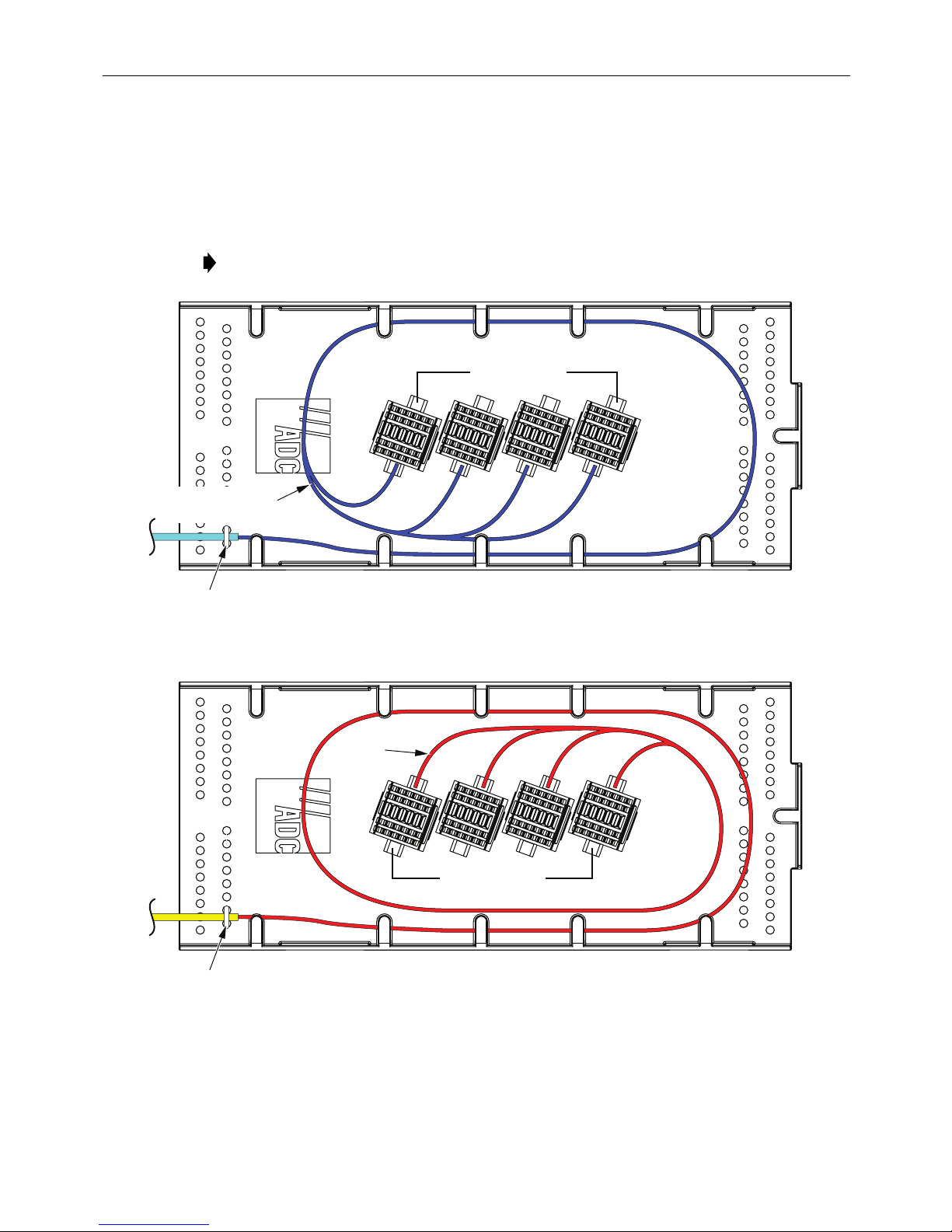
4.1.1 Routing Pigtails
Typically, the termination and splice panel is shipped without adapter packs or pigtails and will
therefore need to be configured as required. Alternatively, the panel may have been ordered with
adapter packs pre-cabled with pigtails or with MPO cassettes already installed. If pigtails need
to be routed in the panel being installed, route the pigtails corresponding to the example shown
in
Figure 17 for a right side adapter pack or Figure 18 for a left side adapter pack.
ADCP-92-098 • Rev C • May 2018
Figure 17. Routing Pigtails from Right Side (Top View)
© 2018 CommScope. All Rights Reserved.
Page 17
Page 18

ADCP-92-098 • Rev C • May 2018
24627-A
SLACK LOOP AROUND OUTSIDE OF
SPLICE TRAY IS NOT REQUIRED
NOTE:
STUB
END
CORRECT LENGTH AT ADAPTER PACK
IF NECESSARY, PULL EACH 900 MICRON FIBER FROM
STUB END OF SUBUNIT, TO CORRECT LENGTH TO
ELIMINATE SLACK AT ADAPTER PACK.
RECOMMENDED CABLE
LENGTH FROM STUB END
TO CONNECTOR IS 108 INCHES
Figure 18 shows routing from the left side.
Figure 18. Routing Pigtails from Left Side (Top View)
4.1.2 Routing OSP Cable, Right Side Entry
For right side cable entry, route the OSP cable from the cable clamp position to the splice tray as
shown in
Figure 19
. Note that “right” is defined here from the perspective of the front of the
panel.
Page 18
© 2018 CommScope. All Rights Reserved.
Page 19

NOTE:
SLACK LOOP AROUND
OUTSIDE OF SPLICE
TRAY IS NOT REQUIRED
CONVOLUTED
TUBING (1 FT)
(PROVIDED)
CABLE CLAMP
(RIGHT SIDE ENTRY)
24628-A
USE HOOK-AND-LOOP STRAP
(PROVIDED) TO SECURE
SPLICE TRAY TO PANEL
RECOMMENDED
BREAKOUT
LENGTH - 120 INCHES
ADCP-92-098 • Rev C • May 2018
Figure 19. Routing OSP Cable, Right Side Entry
© 2018 CommScope. All Rights Reserved.
Page 19
Page 20

ADCP-92-098 • Rev C • May 2018
USE HOOK-AND-LOOP STRAP
(PROVIDED) TO SECURE
SPLICE TRAY TO PANEL
24629-A
NOTE:
SLACK LOOP AROUND
OUTSIDE OF SPLICE
TRAY IS NOT REQUIRED
CONVOLUTED
TUBING (1 FT)
(PROVIDED)
CABLE CLAMP
(LEFT SIDE ENTRY)
RECOMMENDED
BREAKOUT
LENGTH - 120 INCHES
4.1.3 Routing OSP Cable, Left Side Entry
For left side cable entry, route the OSP cable from the cable clamp position to the splice tray as
shown in
Figure 20. “Left” is defined from the front of the panel.
Page 20
© 2018 CommScope. All Rights Reserved.
Figure 20. Routing OSP Cable, Left Side Entry
Page 21
4.1.4 Routing Pigtails and OSP Fibers in Splice Tray
Route the pigtail and OSP fibers in the splice tray as shown in the Figure 21.
Use hook-and-loop strap to secure the splice tray to the panel.
Note: For location of the hook-and-loop strap, refer to Figure 20 on the previous page.
OSP
WWW.ADC.COM WWW.ADC.COM
PIGTAIL FIBERS
FROM ADAPTERS
BREAKOUT
SIDE
ADCP-92-098 • Rev C • May 2018
USE LACING TO
SECURE SUBUNIT
USE LACING TO
SECURE SUBUNIT
PIGTAIL FIBER ROUTING
OSP
FIBERS
PIGTAIL
BREAKOUT
SIDE
OSP FIBER ROUTING
Figure 21. Routing Pigtails and OSP Fibers in Splice Tray
22066-A
© 2018 CommScope. All Rights Reserved.
Page 21
Page 22

ADCP-92-098 • Rev C • May 2018
4.2 Termination Only Panel Procedures
4.2.1 Routing OSP Cable, Right Side Entry (Adapter Packs)
For right side cable entry in a panel with adapter packs, route the OSP cable from the cable
clamp position to the splice tray as shown in
the perspective of the front of the panel.
CONVOLUTED
TUBING
(PROVIDED)
Figure 22. Note that “right” is defined here from
OSP CABLE
BREAKOUT LENGTH -
60 INCHES TOTAL WITH
APPROX. 9 INCHES OF
900 um FIBER EXPOSED
TIE-DOWN
POINT
- DRAWER IN CLOSED POSITION
NOTE:
- TOP COVER NOT SHOWN, FOR CLARITY
- REAR COVER REMOVED
TIE-DOWN
POINT
Figure 22. Routing OSP Cable, Right Side Entry (Adapter Packs)
24630-A
Page 22
© 2018 CommScope. All Rights Reserved.
Page 23

ADCP-92-098 • Rev C • May 2018
4.2.2 Routing OSP Cable, Left Side Entry (Adapter Cassettes)
For left side cable entry in a panel with adapter packs, route the OSP cable from the cable clamp
position to the splice tray as shown in
OSP CABLE
BREAKOUT LENGTH 60 INCHES TOTAL WITH
APPROX. 9 INCHES OF
900 um FIBER EXPOSED
Figure 23. “Left” is defined from the front of the panel.
CONVOLUTED
TUBING
(PROVIDED)
TIE-DOWN
POINT
NOTE:
- DRAWER IN CLOSED POSITION
- TOP COVER NOT SHOWN, FOR CLARITY
- REAR COVER REMOVED
TIE-DOWN
POINT
Figure 23. Routing OSP Cable, Left Side Entry (MPO Cassettes)
24631-A
© 2018 CommScope. All Rights Reserved.
Page 23
Page 24

ADCP-92-098 • Rev C • May 2018
CONVOLUTED
TUBING
(PROVIDED)
OSP CABLE
- DRAWER IN CLOSED POSITION
- TOP COVER NOT SHOWN, FOR CLARITY
- REAR COVER REMOVED
NOTE:
23955-A
CABLES SHOULD BE LONG
ENOUGH TO COMPLETELY
PULL OUT THE SLIDING TRAY
NOTE:
REMOVE THIS
RADIUS LIMITER
FOR LEFT SIDE
ENTRY
4.2.3 Routing OSP Cable, Left Side Entry (MPO Cassettes)
For left side cable entry in a panel with MPO cassettes, route the OSP cable from the cable
clamp position to the MPO casettes as shown in
the perspective of the front of the panel.
Figure 24. Note that “left” is defined here from
Figure 24. Routing OSP Cable, Left Side Entry (MPO Cassettes)
Page 24
© 2018 CommScope. All Rights Reserved.
Page 25

ADCP-92-098 • Rev C • May 2018
CONVOLUTED
TUBING
(PROVIDED)
OSP CABLE
- DRAWER IN CLOSED POSITION
- TOP COVER NOT SHOWN, FOR CLARITY
- REAR COVER REMOVED
NOTE:
23956-A
CABLES SHOULD BE LONG
ENOUGH TO COMPLETELY
PULL OUT THE SLIDING TRAY
NOTE:
REMOVE THIS
RADIUS LIMITER
FOR RIGHT SIDE
ENTRY
4.2.4 Routing OSP Cable, Right Side Entry (MPO cassettes)
For right side cable entry in a panel with MPO cassettes, route the OSP cable from the cable
clamp position to the MPO cassettes as shown in
Figure 25. “Right” is defined from the front of
the panel.
Figure 25. Routing OSP Cable, Right Side Entry (Adapter Packs)
© 2018 CommScope. All Rights Reserved.
Page 25
Page 26
ADCP-92-098 • Rev C • May 2018
4.3 MPO Termination Only Panel Procedures
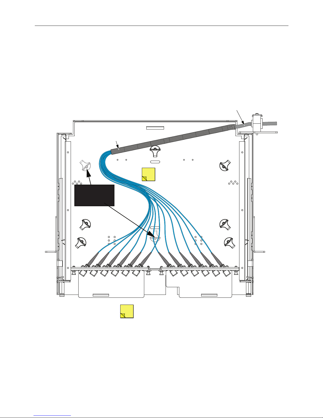
4.3.1 Routing MPO Trunk Cable, Right Side Entry (MPO Adapter Packs)
For right side cable entry in a panel with MPO adapter packs, route the MPO trunk cable from
the cable clamp position to the splice tray as shown in
here from the perspective of the front of the panel.
CONVOLUTED
TUBING
(PROVIDED)
NOTE:
Figure 26. Note that “right” is defined
MPO TRUNK
CABLE
CABLES SHOULD BE LONG
ENOUGH TO COMPLETELY
PULL OUT THE SLIDING TRAY
REMOVE THESE
RADIUS LIMITERS
FOR RIGHT SIDE
ENTRY
- DRAWER IN CLOSED POSITION
NOTE:
- TOP COVER NOT SHOWN, FOR CLARITY
- REAR COVER REMOVED
Figure 26. Routing MPO Trunk Cable, Right Side Entry (MPO Adapter Packs)
22180-A
Page 26
© 2018 CommScope. All Rights Reserved.
Page 27
ADCP-92-098 • Rev C • May 2018
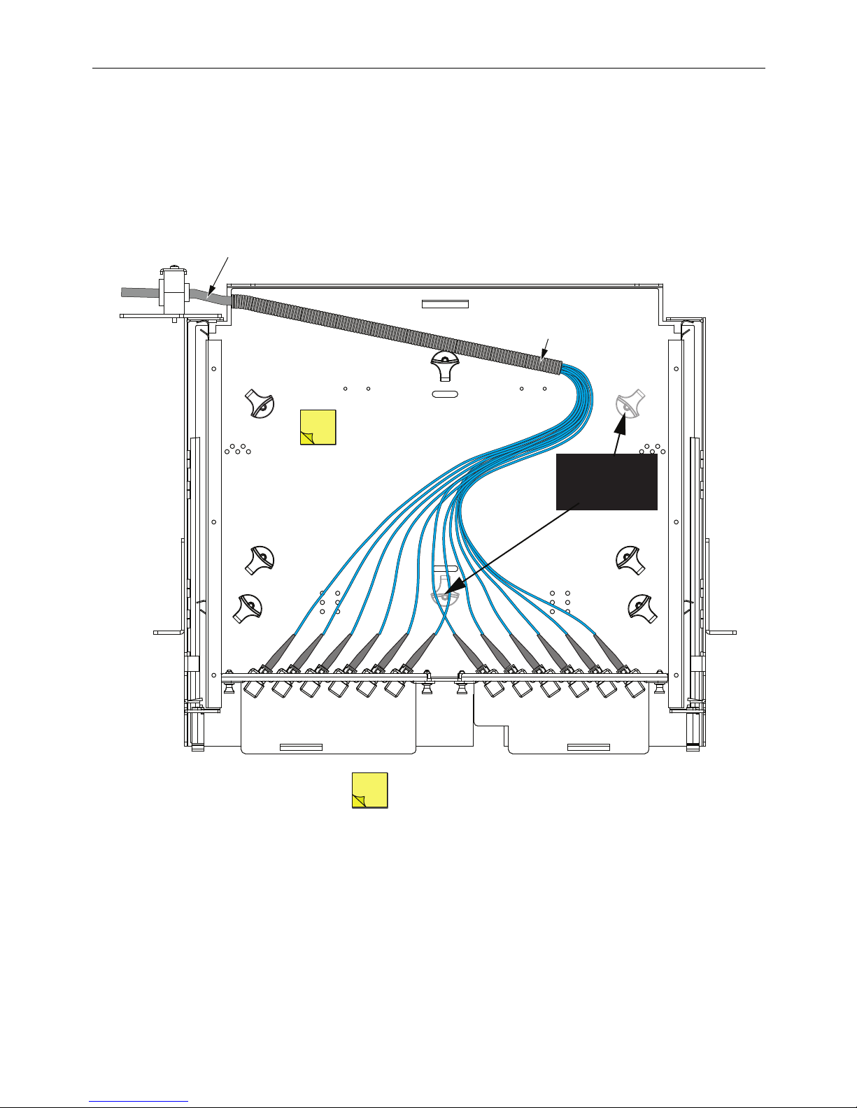
CONVOLUTED
TUBING
(PROVIDED)
- DRAWER IN CLOSED POSITION
- TOP COVER NOT SHOWN, FOR CLARITY
- REAR COVER REMOVED
NOTE:
22181-A
MPO TRUNK
CABLE
CABLES SHOULD BE LONG
ENOUGH TO COMPLETELY
PULL OUT THE SLIDING TRAY
NOTE:
REMOVE THESE
RADIUS LIMITERS
FOR LEFT SIDE
ENTRY
4.3.2 Routing MPO Trunk Cable, Left Side Entry (MPO Adapter Packs)
For left side cable entry in a panel with MPO adapter packs, route the MPO trunk cable from the
cable clamp position to the splice tray as shown in
Figure 27. “Left” is defined from the front of
the panel.
Figure 27. Routing MPO Trunk Cable, Left Side Entry (MPO Adapter Packs)
© 2018 CommScope. All Rights Reserved.
Page 27
Page 28

ADCP-92-098 • Rev C • May 2018
5 CONTACT INFORMATION
• To find out more about CommScope® products, visit us on the web at
www.commscope.com
• For technical assistance, customer service, or to report any missing/damaged parts, visit us at
http://www.commscope.com/SupportCenter
Page 28
 Loading...