

Page 1

User Manual
ADCP-90-545
Issue 4, July 2016
Rack-Mount Panel and Wall-Mount Box
Content Page
INTRODUCTION . . . . . . . . . . . . . . . . . . . . . . . . . . . . . . . . . . . . . . . . . . . . . . . . . . . . . . . . . . . . . . . . . . . . . . . . . . . . . .1
1 UNPACKING AND INSPECTION . . . . . . . . . . . . . . . . . . . . . . . . . . . . . . . . . . . . . . . . . . . . . . . . . . . .
2 RACK-MOUNT PANEL INSTALLATION . . . . . . . . . . . . . . . . . . . . . . . . . . . . . . . . . . . . . . . . . . . . . . . . .
3 WALL-MOUNT BOX INSTALLATION . . . . . . . . . . . . . . . . . . . . . . . . . . . . . . . . . . . . . . . . . . . . . . . . . . .
4 OPERATION. . . . . . . . . . . . . . . . . . . . . . . . . . . . . . . . . . . . . . . . . . . . . . . . . . . . . . . . . . . .
5 TECHNICAL ASSISTANCE. . . . . . . . . . . . . . . . . . . . . . . . . . . . . . . . . . . . . . . . . . . . . . . . . . . . . . .
FL1000
. . . . . . . . . . .2
. . . . . . . . .3
2.1 Installing a Rack-Mount Chassis. . . . . . . . . . . . . . . . . . . . . . . . . . . . . . . . . . . . . . . . . . . . . . . .
2.1.1 19-Inch Rack, 5-Inch Recess (as Shipped). . . . . . . . . . . . . . . . . . . . . . . . . . . . . . . . . . . . . . . . . 3
2.1.2 19-Inch Rack, Flush; 23-Inch Rack, 5-Inch Recess; 23-Inch Rack, Flush. . . . . . . . . . . . . . . . . . . . . 4
2.2 Installing 6pak Adapter Plates and Pigtails . . . . . . . . . . . . . . . . . . . . . . . . . . . . . . . . . . . . . . . . . .
2.2.1 Adapter Plates Without Pigtails (Blank or 6Pak) . . . . . . . . . . . . . . . . . . . . . . . . . . . . . . . . . . . . . 5
2.2.2 Adapter Plates With Pigtails . . . . . . . . . . . . . . . . . . . . . . . . . . . . . . . . . . . . . . . . . . . . . . . . . .
2.3 Installing Cables and Routing Fibers. . . . . . . . . . . . . . . . . . . . . . . . . . . . . . . . . . . . . . . . . . . . .
2.3.1 12-Fiber Termination Rack Mount Panel . . . . . . . . . . . . . . . . . . . . . . . . . . . . . . . . . . . . . . . . . . 8
2.3.2 24-Fiber Termination Rack Mount Panel . . . . . . . . . . . . . . . . . . . . . . . . . . . . . . . . . . . . . . . . . 10
2.3.3 24-Fiber Termination/Splicing Rack-Mount Panel . . . . . . . . . . . . . . . . . . . . . . . . . . . . . . . . . . . 12
2.4 Splicing . . . . . . . . . . . . . . . . . . . . . . . . . . . . . . . . . . . . . . . . . . . . . . . . . . . . . . . . . .
3.1 Installing the Wall-Mount Chassis . . . . . . . . . . . . . . . . . . . . . . . . . . . . . . . . . . . . . . . . . . . . . .
3.2 Installing 6pak Adapter Plates and Pigtails . . . . . . . . . . . . . . . . . . . . . . . . . . . . . . . . . . . . . . . . . .
3.3 Installing Cables and Routing Fibers. . . . . . . . . . . . . . . . . . . . . . . . . . . . . . . . . . . . . . . . . . . . .
3.3.1 12-Fiber Termination/Splicing Wall-Mount Box . . . . . . . . . . . . . . . . . . . . . . . . . . . . . . . . . . . . 19
3.3.2 24-Fiber Termination/Splicing Wall-Mount Box . . . . . . . . . . . . . . . . . . . . . . . . . . . . . . . . . . . . 24
3.3.3 48-Fiber Splicing Wall-Mount Box . . . . . . . . . . . . . . . . . . . . . . . . . . . . . . . . . . . . . . . . . . . . .
3.4 Splicing . . . . . . . . . . . . . . . . . . . . . . . . . . . . . . . . . . . . . . . . . . . . . . . . . . . . . . . . . .
4.1 Installing Patch Cords . . . . . . . . . . . . . . . . . . . . . . . . . . . . . . . . . . . . . . . . . . . . . . . . . . . .
4.2 Cleaning Adapters and Connectors . . . . . . . . . . . . . . . . . . . . . . . . . . . . . . . . . . . . . . . . . . . . . .
. . . . . . . . . . . . .14
. . . . . . . .14
. . . . . . . . . . . . .32
. . . . . . . . . . . . . . .33
. . . . . . . . . .33
. . . . . . . . . . .34
. . . . . . . .3
. . . . . .5
6
. . . . . . . .8
. . . . . . .14
. . . . .17
. . . . . . .19
29
. . . . . . .33
INTRODUCTION
FL1000 products provide solutions for terminating and splicing fibers in small fiber networks. The
product line consists of three rack-mount panels and three wall-mount boxes. The rack-mount panels
include a 12-fiber termination panel, a 24-fiber termination panel, and a 24-fiber termination/splicing
panel. The wall-mount boxes include a 12-fiber termination/splicing box, a 24-fiber termination/
splicing box, and a 48-fiber splicing box. Options include 6pak adapter plates, with or without
pigtails, splice trays, and cable kits.
300001735123 Rev C Page 1
www.commscope.com © 2016 CommScope. All Rights Reserved.
Page 2
ADCP-90-545 • Issue 4 • July 2016
This manual contains all procedures required to install and operate any FL1000 product or product
option. The procedures are presented in the order in which they would normally be done, with
separate installation sections for rack-mount and wall-mount units. Select from the procedures based
on your specific installation.
Revision History
ISSUE DATE REASON FOR CHANGE
Issue 1 09/1998 Original.
Issue 2 04/2001 Non-technical update.
Issue 3 08/2011 Revised for new two-door design for wallbox.
Issue 4 July 2016 Reformatted for CommScope.
Trademark Information
FL1000
is a registered trademark of CommScope . In c.
ST is a registered trademark of AT&T Technologies, Inc.
Admonishments
Important safety admonishments are used throughout this manual to warn of possible hazards to
persons or equipment. The admonishments — in the form o f Dangers, Warnings, and Caution s
— must be followed at all times.
Danger: Danger is used to indicate the presence of a hazard that will cause severe personal
injury, death, or substantial property damage if the hazard is not avoided.
Warning: Warning is used to indicate the presence of a hazard that can cause severe personal
injury, death, or substantial property damage if the hazard is not avoided.
Caution: Caution is used to indicate the presence of a hazard that will or can cause minor
personal injury or property damage if the hazard is not avoided.
1 UNPACKING AND INSPECTION
Unpack and inspect the various components as follows:
1. Inspect the exterior of the shipping container(s) for evidence of rough handling that may
ha
ve damaged the components in the container.
2. Unpack each container while carefully checking the conte
3. File a claim with the commercial carrier and notify BCG Technical Assistance Center, if
damage is detected
4. Save all shipping containers for use if the equipment requires
Page 2
© 2016 CommScope. All Rights Reserved.
nts for damage.
or if parts are missing. Save damaged cartons for inspection by the carrier.
shipment at a future date.
Page 3
2 RACK-MOUNT PANEL INSTALLATION
11247-C
DANGER
INVISIBLE LASER RADIATION
AVOID DIRECT EXPOSURE TO BEAM
CAT #
S/N
DATE
CODE
MADE
IN USA
‚
MOUNTING
BRACKET
POSITIONED
FOR 5-INCH
RECESS
MOVE MOUNTING
BRACKETS TO THIS
POSITION FOR
FLUSH MOUNT
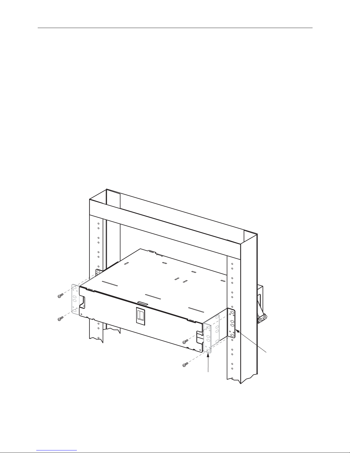
2.1 Installing a Rack-Mount Chassis
The FL1000 rack-mount panel can be installed on either a 19-inch (48.26 cm) or 23-inch (58.42 cm)
rack. It is designed for mounting in an EIA style rack, but a WECO style rack can also be used. It can
be mounted flush on the rack or with a 5-inch (12.7 cm) recess. The panel is shipped ready to be
installed with a 5-inch recess on a 19-inch rack. For other mounting positions, the mounting brackets
must be removed and remounted in a different orientation. Select from the procedures below based
on your specific installation.
ADCP-90-545 • Issue 4 • July 2016
2.1.1 19-Inch Rack, 5-Inch
Recess (as Shipped)
See Figure 1. Use the following procedure.
1. Position the chassis on the rack.
2. Attach the mounting brackets to the rack
using the #12-24 screws supplied.
Figure 1. Installing a Chassis on a 19-Inch Rack
© 2016 CommScope. All Rights Reserved.
Page 3
Page 4
ADCP-90-545 • Issue 4 • July 2016
11248-C
DANGER
INVISIBLE LASER RADIATION
AVOID DIRECT EXPOSURE TO BEAM
CAT #
S/N
DATE
CODE
MADE
IN USA
‚
MOUNTING
BRACKET
POSITIONED
FOR 5-INCH
RECESS
MOVE MOUNTING
BRACKETS TO THIS
POSITION FOR
FLUSH MOUNT
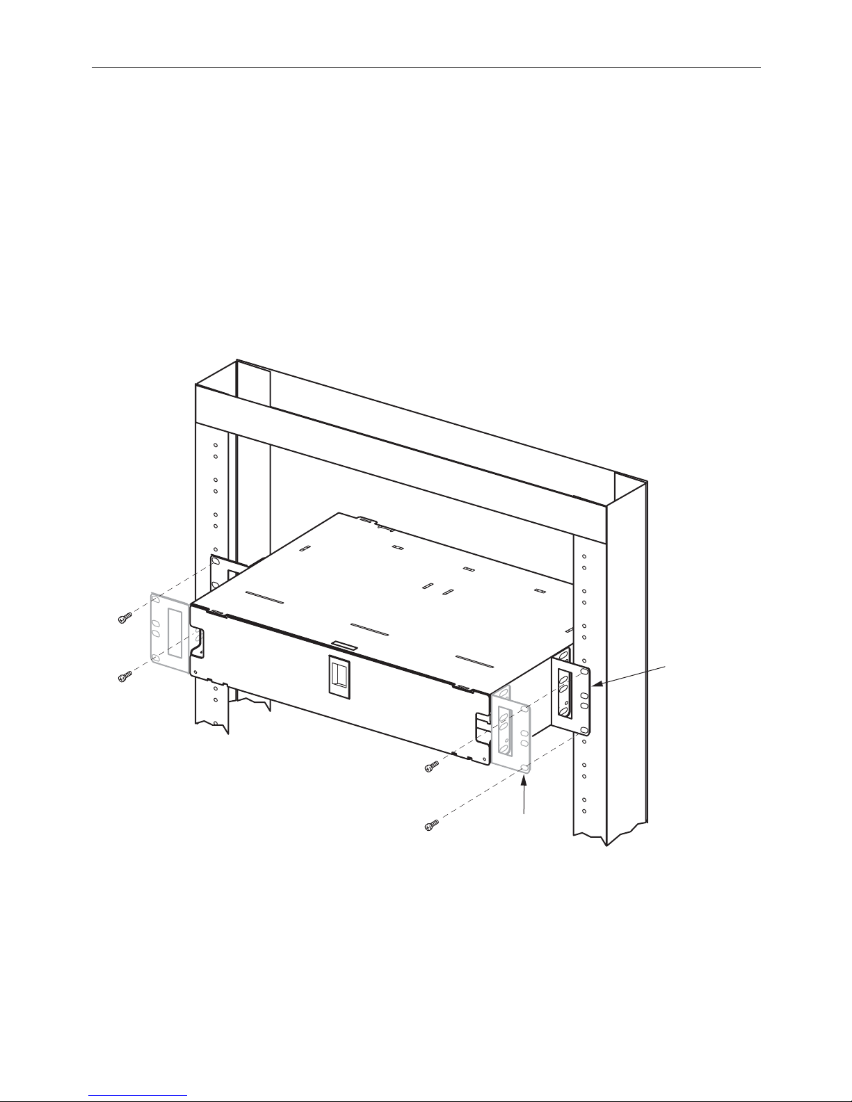
2.1.2 19-Inch Rack, Flush; 23-Inch Rack, 5-Inch Recess; 23-Inch Rack, Flush
For these positions, the mounting brackets must be removed and remounted
orientation. Use the following procedure.
1. Remove the mounting brackets.
2. Remount the mounting brackets
in the position shown:
a. For 19-inch rack, flush mount, use Figure 1 forward position;
b. For 23-inch rack, 5-inch
recess mount, use Figure 2 back position;
c. For 23-inch rack, flush mount, use Figure 2 forward position.
3. Attach the mounting brackets to the rack
using the #12-24 screws supplied.
in a different
Page 4
© 2016 CommScope. All Rights Reserved.
Figure 2. Installing a Chassis on a 23-Inch Rack
Page 5

2.2 Installing 6pak Adapter Plates and Pigtails
The 6pak adapter plates may be any of several types including:
• Simplex or duplex with adapters only
• Blank plates for filling in unused slots
ADCP-90-545 • Issue 4 • July 2016
• Simplex or duplex with adapters and attached pi
gtails
To install adapter plates without pigtails, refer to the first procedure below. To install adapter
plates with pigtails, refer to the second procedure. Adapter plat
es with pigtails are used in the
24-fiber termination/splicing panel only.
2.2.1 Adapter Plates Without Pigtails (Blank or 6Pak)
Use the following procedure to install blanks
or 6pak plates without pigtails:
1. Remove the front cover.
2. Align the adapter plate tabs with
3. Slide the 6pak or blank up into the slot until
the notches in the mounting slot as shown in Figure 3.
it snaps in place.
SLOT
SPLICE
DECK
END
TAB
6 PAK PLATE
(LOADED)
Figure 3. Installing 6pak Plates
11418-B
Page 5
© 2016 CommScope. All Rights Reserved.
Page 6
ADCP-90-545 • Issue 4 • July 2016
2.2.2 Adapter Plates With Pigtails
Use the following procedure to install 6pak plates wit
h pigtails in the 24-fiber termination/splicing
panel.
1. Remove the front cover and slide out the splice deck.
2. Thread the pigtails through the empty mounting slot and loop the pigtails around the
radius limiters i
n the chassis as shown in Figure 4.
END
TAB
SLOT
6 PAK PLATE
(LOADED)
11367-C
SPLICE
DECK
RADIUS LIMITER
(4 PLACES)
PIGTAILS
Figure 4. Installing 6pak Plates with Pigtails
3. Align the adapter plate tabs with the notches in the mounting slot as shown in Figure 4.
4. Slide the 6pak plate into the
5. Fan out the fibers and tie them
slot until it snaps in place.
to the radius limiter on the right rear side of the splice deck
as shown in Figure 5. To tie the fibers, use cord lacing.
6. Route the fibers to the splice tray. For an
illustration of correct routing, refer to
subsection 3.4, Splicing, below.
Page 6
© 2016 CommScope. All Rights Reserved.
Page 7

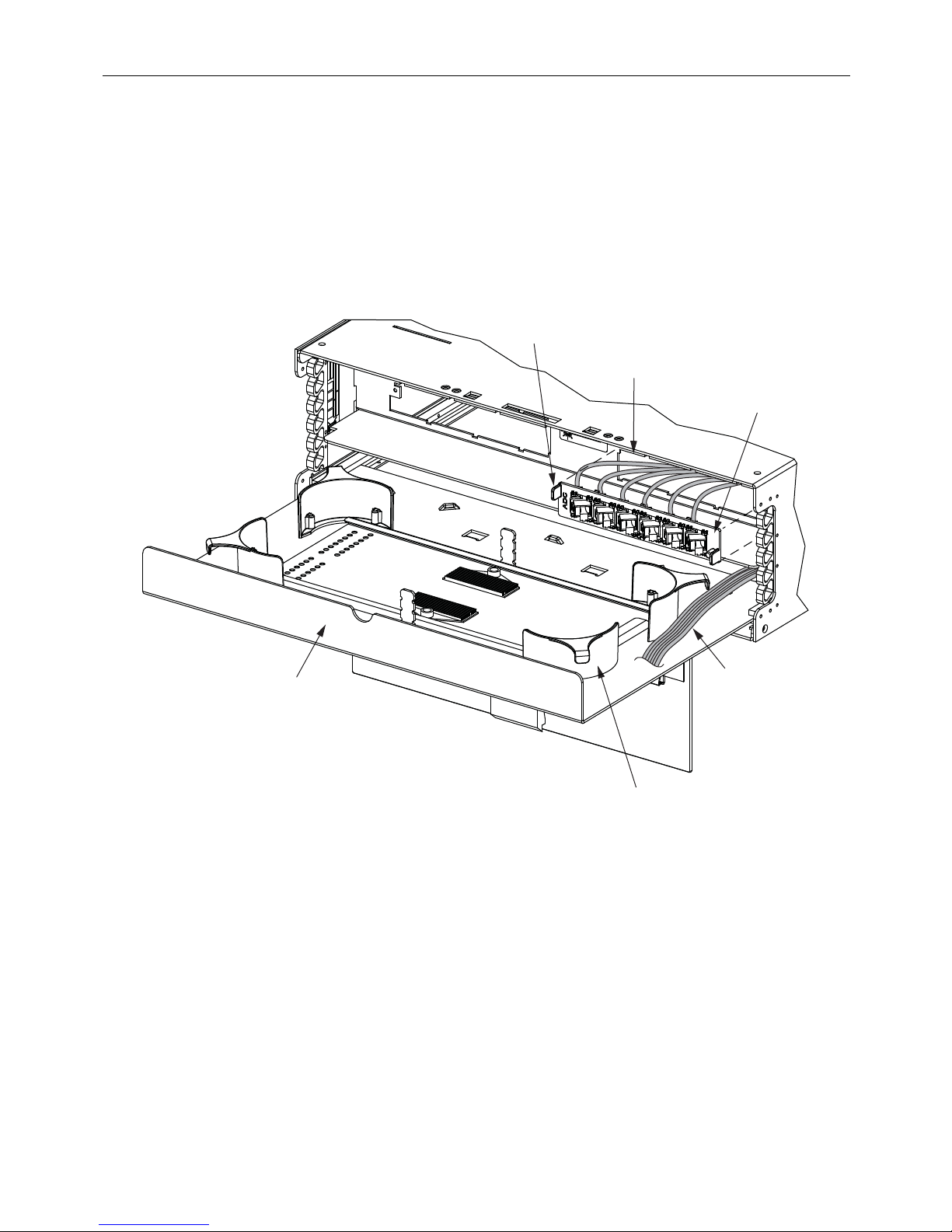
TOP VIEW WITH SPLICE DRAWER CLOSED
TOP VIEW WITH SPLICE DRAWER OPEN
TIE DOWN
USING CORD
LACING
TIE DOWN
USING CORD
LACING
11434-B
PROPER BEND RADIUS
MUST BE MAINTAINED
ADCP-90-545 • Issue 4 • July 2016
Figure 5. Correct Pigtail Routing within 24-Fiber Termination/Splicing Module
© 2016 CommScope. All Rights Reserved.
Page 7
Page 8

ADCP-90-545 • Issue 4 • July 2016
2.3 Installing Cables and Routing Fibers
The rack-mount panel can accommodate either IFC or OSP cable. The procedures used to
install the cable differ slightly for the three chassis types (12-fiber termination panel, 24-fiber
termination panel, and 24-fiber termination/splicing panel). Refer to the appropriate topic below
for the type being installed.
2.3.1 12-Fiber Termination Rack Mount Panel
Figure 6 shows cable routing options and breakout dimensions for the 12-fiber termin ation rack-
mount panel. The cable can enter from above or below
Use the following procedure to install the cable.
the chassis and from the left or right side.
1. Route the cable to the chassis and break out the ca
ble corresponding to Figure 6.
2. Secure the cable as follows:
a. Fasten the tie-down bracket to the panel at t
he cable point of entry using the screws
provided.
b. Position the cable on the tie down bracket with the ca
ble sheath extending about 0.75 inch
(1.9 cm) beyond the bracket into the chassis.
c. Tie down the cable using cord lacing.
d. Secure the cable in a second location on the
rack or wall using a user-provided clamp
per local practice.
3. Remove the front access door and s
4. Route the buffers within the chassis from the cable point of entry to the opposite
lide out the bulkhead deck.
side of
the bulkhead deck, as shown in Figure 6.
5. Tie down the buffers in the location shown in Figure 6 using cord lacing secured to the lan ce.
6. At the buffer breakout point, fan out the fibers
from the buffers and secure them using a
curly lock at the location shown in Figure 6.
Danger: Infrared radiation is invisible and can seriously damage the retina of the eye. Do not
look into the optical bulkhead of an operational transmitter, or into the launching (output) end
of an active fiber. A clean, protective cap or hood MUST be immediately placed over any
radiating bulkhead receptacle or optical fiber connector to avoid exposure to potentially
dangerous amounts of radiation. This practice also helps prevent contamination of connectors
and adapters.
7. Connect the fiber connectors to the adapters on the rear of the 6pak adapter plate.
8. Slide in the bulkhead deck
9. Replace the front access cover.
Page 8
© 2016 CommScope. All Rights Reserved.
to its closed position.
Page 9

ADCP-90-545 • Issue 4 • July 2016
IFC OR OSP
CABLE
SHEATH
CABLE ENTRY
FROM LEFT
TIE OFF USING
TIE-DOWN BRACKET
SUPPLIED WITH PANEL
A
18.0 IN.
(47.72 CM)
SUB-UNITS
A
(220.98 CM)
B
C
87.0 IN.
(134.62 CM)
53.0 IN.
D
C
16.0 IN.
(40.64 CM)
FIBERS
B
TIE DOWN ON OPPOSITE
SIDE FROM ENTRY USING
CORD LACING SECURED
CONNECTORS
ON LANCE
ATTACH USING
CURLY LOCK
SUPPLIED WITH
PANEL
TIE DOWN ON OPPOSITE
SIDE FROM ENTRY USING
CORD LACING SECURED
ON LANCE
D
A
B
C
D
Figure 6. Cable Breakout for 12-Fiber Panel
CABLE ENTRY
FROM RIGHT
TIE OFF USING
TIE-DOWN BRACKET
SUPPLIED WITH PANEL
11246-D
© 2016 CommScope. All Rights Reserved.
Page 9
Page 10
ADCP-90-545 • Issue 4 • July 2016
2.3.2 24-Fiber Termination Rack Mount Panel
Figure 7 shows cable routing options and breakout dimensions for the 24-fiber termin ation rack-
mount panel. The cable can enter from above or below
the chassis and from the left or right side.
IFC OR OSP
CABLE
SHEATH
CABLE ENTRY
FROM LEFT
TIE DOWN
USING CORD
LACING
A
57.0 IN.
(144.78 CM)
41.0 IN.
(104.14 CM)
SUB-UNITS
A
B
C
B
16.0 IN.
(40.64 CM)
FIBERS
C
CONNECTORS
Use the following procedure to install a cable in the 24-fiber termination rack-mount panel.
Page 10
© 2016 CommScope. All Rights Reserved.
C
Figure 7. Cable Breakout for 24-Fiber Panel
A
CABLE ENTRY
FROM RIGHT
B
TIE DOWN
USING CORD
LACING
11245-E
Page 11

ADCP-90-545 • Issue 4 • July 2016
CLAMP
BRACKET
11363-B
CLAMP
YOKES (2)
RUBBER
GROMMET
USE EITHER COVER
OR PLATE IN THIS
POSITION
COVER
NUTS (2)
PLATE
1. Route the cable to the chassis and break out the cable corresponding to Figure 7.
2. Secure the cable as follows (see Figure 8):
a. Install the clamp bracket at the chosen clamp lo
cation by inserting the two integral
bolts from inside the chassis.
b. Sort through the rubber grommets in the kit and find the
one that best fits the cable. If
the cable is too small to fit snugly in the smallest grommet, build up the cable with
tape of a suitable material per local standards.
c. Assemble the cable clamp components on the bracket studs in the order shown in the
figu
re and secure with the two nuts provided.
Figure 8. Installing a Cable Clamp on a Rack-Mount Panel (Select from Four Mounting Locations)
3. If the cable being installed is an OSP cable with a metallic strength member, bond the
cable to ground following the instructions for the bonding/grounding kit.
4. Remove the rear door, if not already removed.
5. Route the fibers within the chas
position shown.
sis as shown in Figure 7 and tie down the fibers in the B
Page 11
© 2016 CommScope. All Rights Reserved.
Page 12

ADCP-90-545 • Issue 4 • July 2016
Danger: Infrared radiation is invisible and can seriously damage the retina of the eye. Do not
look into the optical bulkhead of an operational transmitter, or into the launching (output) end
of an active fiber. A clean, protective cap or hood MUST be immediately placed over any
radiating bulkhead receptacle or optical fiber connector to avoid exposure to potentially
dangerous amounts of radiation. This practice also helps prevent contamination of connectors
and adapters.
6. Connect the fiber connectors to the adaptors on the rear of the 6pak adapter plate.
7. Replace the rear door.
2.3.3 24-Fiber Termination/Splicing Rack-Mount Panel
Figure 9 shows cable routing options and breakout dimensions for the 24-fiber termin ation rack-
mount panel. The cable can enter from above or below
the chassis and from the left or right side.
Use the following procedure to install a cable in the 24-
fiber termination/splicing rack-mount panel.
1. Route the cable to the chassis.
2. Pull out the splice drawer and thread the cable stub through the chassis
onto the splice tray
in the approximate position shown in Figure 9. Based on the figure, determine how much
length of cable will be required for the B to C double loop section shown.
3. Break out the cable, leaving 36 inches (91.
4. Secure the cable with a cable clamp in the position shown,
44 cm) of bare fiber for a splicing loop.
about 0.75 inches (1.91 cm)
before the breakout point. For instructions refer to Figure 8 in the previous procedure.
5. Tie the fibers down with cord lacing
6. If the cable being installed is an OSP cable
in the B position shown in Figure 9.
with a metallic strength member, bond the
cable to ground following the instructions for the bonding/grounding kit.
Page 12
© 2016 CommScope. All Rights Reserved.
Page 13

ADCP-90-545 • Issue 4 • July 2016
IFC OR OSP
CABLE
SHEATH
A
A
18.0 IN.
(20.32 CM)
B DC
TWO FULL
LOOPS
SUB-UNITS
D
36.0 IN.
(91.4 CM)
FIBERS
TIE DOWN CABLE
ON OPPOSITE
SIDE FROM ENTRY
B
C
PREFERRED
TO USE PANEL AS SHIPPED
WITH PIGTAILS LOADED, ROUTE
CABLE IN FROM REAR LEFT
AND ROUTE CLOCKWISE
TO BRING CABLE IN FROM
RIGHT REAR, ROUTE CABLE
COUNTER-CLOCKWISE.
ALSO, REMOVE AND REROUTE
PIGTAILS COUNTER-CLOCKWISE
TIE DOWN CABLE
ON OPPOSITE
SIDE FROM ENTRY
Figure 9. Fiber Routing in 24-Fiber Termination/Splicing Panel
© 2016 CommScope. All Rights Reserved.
11232-D
Page 13
Page 14

ADCP-90-545 • Issue 4 • July 2016
2.4 Splicing
Use the following procedure for splicing.
1. Place a splice tray in the splice drawer (if not already there).
2. Route the fiber into the splice tray on the same side as the
pigtail fiber that it is going to be
spliced to, as shown in Figure 10. Loop the fiber around twice in the splice tray.
3. Splice per local practice.
4. Tie down the fibers with cord lacing in
the C position shown in Figure 10. Refer also to
Figure 9 for correct routing.
C
LEFT
C
3 WALL-MOUNT BOX INSTALLATION
3.1 Installing the Wall-Mount Chassis
Note: If using a cable clamp (as opposed to a compression fitting), install the cable clamp
prior to mounting the box on the wall.
FL1000 wall-mount boxes can be mounted directly to any wall, but CommScope recommends that
they be mounted, using the #12 woodscrews supplied with the unit, on a 3/4-inch thick plywood
panel that is attached to the wall in accordance with local fire code.
Page 14
© 2016 CommScope. All Rights Reserved.
11419-A
RIGHT
Figure 10. Routing Fibers on a Splice Tray
Page 15

ADCP-90-545 • Issue 4 • July 2016
3.55 IN.
(9.0 CM)
10.07 IN.
(25.6 CM)
MOUNTING
HOLE
(4 PLACES)
12.80 IN.
(32.5 CM)
3.55 IN.
(9.0 CM)
4.22 IN.
(10.7 CM)
8.23 IN.
(20.9 CM)
14.00 IN.
(35.6 CM)
11.23 IN.
(28.5 CM)
TOP VIEW
FRONT VIEW
24562-A
Use the following procedure.
1. Make sure the location provides room for the door to swing out. See Figure 11 and Figure 12.
2. Position the box in its assigned
location and mark the mounting hole locations.
3. Fasten using the four #10-1.25 inch wood screws provided. See Figure 11 and Figure 12
for mounting hole location.
Figure 11. 12-Fiber Wall-Mount Box Dimensions
© 2016 CommScope. All Rights Reserved.
Page 15
Page 16

3.55 IN.
(9.0 CM)
10.07 IN.
(25.6 CM)
MOUNTING
HOLE
(4 PLACES)
12.80 IN.
(32.5 CM)
3.55 IN.
(9.0 CM)
4.22 IN.
(10.7 CM)
12.00 IN.
(30.5 CM)
14.00 IN.
(35.6 CM)
15.00 IN.
(38.1 CM)
TOP VIEW
FRONT VIEW
24563-A
ADCP-90-545 • Issue 4 • July 2016
Figure 12. 24/48 Wall-Mount Box Dimensions
Page 16
© 2016 CommScope. All Rights Reserved.
Page 17

3.2 Installing 6pak Adapter Plates and Pigtails
PIGTAILS
SLOT
END TAB
END TAB
6 PAK PLATE
(LOADED)
24565-A
Wall-mount boxes with a termination function have mounting slots for 6pak adapter plates. The
6pak adapter plates may be any of several types including:
• Simplex or duplex with adapters only
• Blank plates for filling in unused slots
ADCP-90-545 • Issue 4 • July 2016
• Simplex or duplex with adapters and attached pi
Use the following procedure to install
adapter plates.
1. If the 6pak plate has attached pigtails, thread
gtails
the pigtails through the empty mounting slot
and loop the pigtails around the radius limiters in the chassis, as shown in Figure 13 belo w.
Figure 13. Installing a 6Pak Plate with Pigtails in a Wall-Mount Box
Page 17
© 2016 CommScope. All Rights Reserved.
Page 18

ADCP-90-545 • Issue 4 • July 2016
24569-A
24568-A
2. Align the tabs on the 6pak plate with the notches in the mounting slot.
3. Slide the 6pak or blank up into the slot until
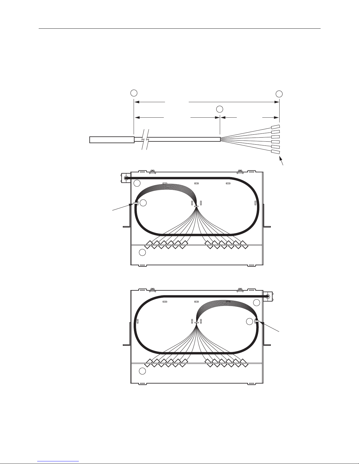
4. If installing pigtails, route the fibers within
it snaps in place.
the chassis corresponding to Figure 14 and
Figure 15 for the 12-fiber and 24-fiber termination/splicing panel, respecti
Figure 14. Pigtail Routing in 12-Fiber Termination/Splicing Panel
vely.
Figure 15. Pigtail Routing in 24-Fiber Termination/Splicing Panel
Page 18
© 2016 CommScope. All Rights Reserved.
Page 19

3.3 Installing Cables and Routing Fibers
IFC OR OSP
CABLE
A
B
C
SHEATH
45.0 IN.
(114.3 CM)
64.0 IN.
(162.6 CM)
19.0 IN.
(48.3 CM)
SUB-UNITS
FIBERS
CONNECTORS
24570-A
ROUTED
FROM TOP
C
B
A
RADIUS
LIMITERS
The cable must be routed within the chassis in an orderly way that provides maximum
protection for the fibers and ease in future maintenance. For details refer to the following topics
for the three different types of wall-mount boxes. When routing and terminating fibers, observe
the following precaution to avoid potential eye damage.
Danger: Infrared radiation is invisible and can seriously damage the retina of the eye. Do not
look into the optical bulkhead of an operational transmitter, or into the launching (output) end
of an active fiber. A clean, protective cap or hood MUST be immediately placed over any
radiating bulkhead receptacle or optical fiber connector to avoid exposure to potentially
dangerous amounts of radiation. This practice also helps prevent contamination of connectors
and adapters.
3.3.1 12-Fiber Termination/Splicing Wall-Mount Box
ADCP-90-545 • Issue 4 • July 2016
This unit can be used for either fiel
correct breakout for field termination. Figure 18 shows the correct breakout for
d termination or splicing. Figure 16 and Figure 17 show the
splicing.
Figure 16. Field Termination Breakout and Routing, 12-Fiber Wall-Mount Box (Top Entry)
Page 19
© 2016 CommScope. All Rights Reserved.
Page 20

IFC OR OSP
CABLE
A
B
B
C
C
SHEATH
45.0 IN.
(114.3 CM)
64.0 IN.
(162.6 CM)
19.0 IN.
(48.3 CM)
SUB-UNITS
FIBERS
CONNECTORS
24573-A
ROUTED
FROM BOTTOM
A
RADIUS
LIMITERS
ADCP-90-545 • Issue 4 • July 2016
Figure 17. Field Termination Breakout and Routing, 12-Fiber Wall-Mount Box (Bottom Entry)
Page 20
© 2016 CommScope. All Rights Reserved.
Page 21

ADCP-90-545 • Issue 4 • July 2016
IFC OR OSP
CABLE
SHEATH
A
ROUTED FROM TOP
63 - 69 IN.
(160 - 175 CM)
SUB-UNITS
B C
36 IN. MIN.
(91.44 CM)
FIBERS
RADIUS
LIMITER
PLACE GROMMETS
ON EACH RADIUS
LIMITER BEHIND
AND IN FRONT OF
SPLICE TRA Y
CORNER OF
SPLICE TRA Y
24578-A
ROUTED FROM BOTTOM
Figure 18. Splicing Breakout and Routing, 12-Fiber Wall-Mount Box
© 2016 CommScope. All Rights Reserved.
Page 21
Page 22

ADCP-90-545 • Issue 4 • July 2016
CLAMP
BRACKET
INTEGRAL
BOLTS
CLAMP
YOKES (2)
RUBBER
GROMMET
PLATE
NUTS (2)
24566-A
Use the following procedure to prepare and install the cable.
1. Determine whether a cable clamp or compression
fitting will be used to hold the cable. In
general, a cable clamp is intended for a larger diameter cable, but either method can be
used for securing the cable.
2. Strip the outer sheath of the cable to expose the inner fiber bundles. Figure 16 and
Figure 17 show the correct breakout for
for splicing. The cable sheath sho
termination. Figure 18 shows the correct breakout
uld extend about 0.75 inch (1.9 cm) beyond the cable
clamp or compression fitting.
3. If using a cable clamp (Figure 19):
a. Before mounting the wall-mount chassis to the
wall, determine which of the four
available mounting locations will be used and install the clamp bracket by inserting the
two integral bolts from the rear, as shown. If the cable is routed to the wall box from
above, install the cable clamp bracket in the upper part of the box. If the cable is routed
to the wall box from below, install the cable clamp bracket in the lower part of the box.
b. Sort through the rubber grommets in the kit and find the
one that best fits the cable. If
the cable is too small to fit snugly in the smallest grommet, build up the cable with
tape of a suitable material per local standards.
c. Assemble the cable clamp components on the integral bolts in the order shown in the
re and secure with the two nuts provided.
figu
Figure 19. Cable Clamp Assembly (Select from Four Mounting Locations)
Page 22
© 2016 CommScope. All Rights Reserved.
Page 23

4. If using a compression fitting (Figure 20):
a. Thread the cable through the cap and housing.
b. Determine which of the eight available mounting slots wi
housing into the slot.
c. Fasten to box using lock nut provided.
d. Turn cap clockwise until tight on cable.
ADCP-90-545 • Issue 4 • July 2016
ll be used and insert the
CAP
GASKET
WASHER
TPE
BUSHING
HOUSING
COMPRESSION
FITTING BRACKET
SLOT
GROMMIT
LOCK
NUT
Figure 20. Compression Fitting (Select from Eight Mounting Locations)
24567-A
5. If the cable being installed is an OSP cable with a metallic strength member, bond the
cable to ground following the instructions for the bonding/grounding kit.
© 2016 CommScope. All Rights Reserved.
Page 23
Page 24

ADCP-90-545 • Issue 4 • July 2016
6. Route the fibers within the wall-mount box as shown in Figure 16, Figure 17, and
Figure 18. Tie the fibers down in the loc
Danger: Infrared radiation is invisible and can seriously damage the retina of the eye. Do not
look into the optical bulkhead of an operational transmitter, or into the launching (output) end
of an active fiber. A clean, protective cap or hood MUST be immediately placed over any
radiating bulkhead receptacle or optical fiber connector to avoid exposure to potentially
dangerous amounts of radiation. This practice also helps prevent contamination of connectors
and adapters.
7. Refer to subsection 3.4, Splicing for splicing instructions.
3.3.2 24-Fiber Termination/Splicing Wall-Mount Box
ation shown using cord lacing.
This unit can be used for either fiel
correct breakout for field termination when the
d termination or splicing. Figure 21 and Figure 22 show the
cable is routed in from the top. Figure 23 and
Figure 24 show the correct breakout for field termination when the cable is routed
bottom. Figure 25 shows the correct breakout for splicing.
C
CONNECTORS
IFC OR OSP
CABLE
SHEATH
A
86.0 IN.
(218.4 CM)
67.0 IN.
(170.2 CM)
SUB-UNITS
RADIUS
LIMITERS
A
C
B
19.0 IN.
(48.3 CM)
FIBERS
ROUTE TOP
THREE FIBERS
AROUND BOTH
RADIUS LIMITERS
in from the
Figure 21. Field Termination Breakout and Routing, 24-Fiber Wall-M ount Box (Top Entry, Top 6paks)
Page 24
© 2016 CommScope. All Rights Reserved.
B
TOP 6 PAKS
(ROUTED FROM TOP)
ROUTE BOTTOM
THREE FIBERS
AROUND LEFT
RADIUS LIMITER
ONLY
24574-A
Page 25

ADCP-90-545 • Issue 4 • July 2016
IFC OR OSP
CABLE
SHEATH
A
92.0 IN.
(233.7 CM)
67.0 IN.
(170.2 CM)
SUB-UNITS
RADIUS
LIMITERS
A
B
C
B
25.0 IN.
(63.5 CM)
FIBERS
BOTTOM FIBERS
AROUND LEFT
RADIUS LIMITER
C
CONNECTORS
ROUTE
ONLY
BOTTOM 6 PAKS
(ROUTED FROM TOP)
24576-A
Figure 22. Field Termination Breakout and Routing, 24-Fiber Wall-Mount Box (Top Entry, Bottom 6paks)
© 2016 CommScope. All Rights Reserved.
Page 25
Page 26

ADCP-90-545 • Issue 4 • July 2016
IFC OR OSP
CABLE
SHEATH
A
100.0 IN.
(254.0 CM)
81.0 IN.
(205.7 CM)
SUB-UNITS
RADIUS
LIMITERS
C
B
B
19.0 IN.
(48.3 CM)
FIBERS
ROUTE TOP
THREE FIBERS
AROUND BOTH
RADIUS LIMITERS
ROUTE BOTTOM
THREE FIBERS
AROUND LEFT
RADIUS LIMITER
C
CONNECTORS
ONLY
A
TOP 6 PAKS
(ROUTED FROM BOTTOM)
24575-A
Figure 23. Field Termination Breakout and Routing, 24-Fiber Wall-Mount Box (Bottom Entry, Top 6paks)
Page 26
© 2016 CommScope. All Rights Reserved.
Page 27

ADCP-90-545 • Issue 4 • July 2016
IFC OR OSP
CABLE
SHEATH
A
106.0 IN.
(269.2 CM)
81.0 IN.
(205.7 CM)
SUB-UNITS
RADIUS
LIMITERS
B
C
B
25.0 IN.
(63.5 CM)
FIBERS
BOTTOM FIBERS
AROUND LEFT
RADIUS LIMITER
C
CONNECTORS
ROUTE
ONLY
A
BOTTOM 6 PAKS
(ROUTED FROM BOTTOM)
24577-A
Figure 24. Field Termination Breakout and Routing, 24-Fiber Wall-Mount Box (Bottom Entry, Bottom 6paks)
© 2016 CommScope. All Rights Reserved.
Page 27
Page 28

ADCP-90-545 • Issue 4 • July 2016
IFC OR OSP
CABLE
SHEATH
A
ROUTED FROM TOP
104 - 110 IN.
(264 - 279 CM)
SUB-UNITS
B C
36 IN. MIN.
(91.44 CM)
FIBERS
RADIUS
LIMITER
CORNER OF
SPLICE TRA Y
24578-A
ROUTED FROM BOTTOM
Figure 25. Splicing Breakout and Routing 24-Fiber Wall-Mount Box
PLACE GROMMETS
ON EACH RADIUS
LIMITER BEHIND
AND IN FRONT OF
SPLICE TRA Y
Use the following procedure to prepare and install the cable.
Page 28
© 2016 CommScope. All Rights Reserved.
Page 29

ADCP-90-545 • Issue 4 • July 2016
1. Determine whether a cable clamp or compression fitting will be used to hold the cable. In
general, a cable clamp is intended for a larger diameter cable, but either method can be
used for securing the cable.
2. Strip the outer sheath of the cable to
Figure 23, and Figure 24 show the correct breakout for terminat
correct breakout for splicing. The cable sheath sh
expose the inner fiber bundles. Figure 21, Figure 22,
ion. Figure 25 shows the
ould extend about 0.75 inch (1.9 cm)
beyond the cable clamp or compression fitting.
3. If using a cable clamp, refer to Figure 19 and associated text in the procedure
above for the
12-fiber wall-mount box.
4. If using a compression fitting, refer to Figure 20 and associated text in the procedure
above for the 12-fiber wall-mount box.
5. If the cable being installed is an OSP cable
with a metallic strength member, bond the
cable to ground following the instructions for the bonding/grounding kit.
6. Route the fibers within the wall-mount box as shown in Figure 21, Figure 22, Figure 23,
Figure 24, or Figure 25. Tie the fibers down in the location shown using cord lacing.
Danger: Infrared radiation is invisible and can seriously damage the retina of the eye. Do not
look into the optical bulkhead of an operational transmitter, or into the launching (output) end
of an active fiber. A clean, protective cap or hood MUST be immediately placed over any
radiating bulkhead receptacle or optical fiber connector to avoid exposure to potentially
dangerous amounts of radiation. This practice also helps prevent contamination of connectors
and adapters.
7. Refer to subsection 3.4, Splicing, below, for splicing instructions.
3.3.3 48-Fiber Splicing Wall-Mount Box
Figure 26 shows the three routing options within the
mount box. At least two cables are always inv
olved. They may both enter from the top, both
chassis for the 48-fiber splicing wall-
enter from the bottom, or enter from both top and bottom, on the left side. If from top and
bottom, then an “S” curve, under the splice tray, must be used to reverse the direction of one
cable so that they may both enter the splice tray from the bottom.
© 2016 CommScope. All Rights Reserved.
Page 29
Page 30

24581-A
IFC OR OSP
CABLE
A
B C
SHEATH
36.0 IN.
(91.44 CM)
110 - 116 IN.
(279 - 295 CM)
SUB-UNITS
FIBERS
BOTH BUNDLES
ROUTED FROM TOP
IFC OSP
IFC OSP
BOTH BUNDLES
ROUTED FROM BOTTOM
ROUTED FROM BOTTOM
OSP
ROUTED FROM TOP
IFC
RADIUS
LIMITER
PLACE GROMMETS
ON EACH RADIUS
LIMITER BEHIND
AND IN FRONT OF
SPLICE TRA YS
CORNER OF
SPLICE TRA YS
ADCP-90-545 • Issue 4 • July 2016
Page 30
© 2016 CommScope. All Rights Reserved.
Figure 26. Routing within 48-Fiber Splicing Wall-Mount Box
Page 31

Use the following procedure to route the cable.
ADCP-90-545 • Issue 4 • July 2016
1. Determine whether a cable clamp
or compression fitting will be used to hold the cables. In
general, a cable clamp is intended for a larger diameter cable, but either method can be
used for securing the cable.
2. Strip the outer sheath of the cables to expose the inner fiber bundles as shown in Figure 26
above. The cable sheath should extend about 0.75 inch (1.9 c
m) beyond the cable clamp or
compression fitting.
3. If using a cable clamp, refer to Figure 19 and associated text in the procedure
above for the
12-fiber wall-mount box.
4. If using a compression fitting, refer to Figure 20 and associated text in the procedure
above for the 12-fiber wall-mount box.
5. If either cable being installed is an OSP cable
with a metallic strength member, bond the
cable to ground following the instructions for the bonding/grounding kit.
6. Route the fibers within the wa
in the location shown
using cord lacing.
ll-mount box as shown in Figure 26 and tie the fibers down
Danger: Infrared radiation is invisible and can seriously damage the retina of the eye. Do not
look into the optical bulkhead of an operational transmitter, or into the launching (output) end
of an active fiber. A clean, protective cap or hood MUST be immediately placed over any
radiating bulkhead receptacle or optical fiber connector to avoid exposure to potentially
dangerous amounts of radiation. This practice also helps prevent contamination of connectors
and adapters.
7. Refer to subsection 3.4, Splicing, below, for splicing instructions.
© 2016 CommScope. All Rights Reserved.
Page 31
Page 32

ADCP-90-545 • Issue 4 • July 2016
3.4 Splicing
Use the following procedure to install a splice tray and set up a splice.
1. If there is an “S” fiber curve within the cha
ssis and crossing through the area where the
splice tray will be installed, place grommets on the radius limiters to hold the splice tray
above the “S” curve. (Refer to previous topic for an illustration of the grommets).
2. Place the splice tray within the radius limiters
in the desired orientation based on the
routing diagrams presented in the foregoing topics.
3. Route all fibers to the open end of the splice tray (witho
ut foldover tab), divided into left and
right groups corresponding to which splice chip they are going to be splice at. Figure 27
shows the recommended route within the splice tray using this
method. Tie down the fibers
with cord lacing using the tie-down holes (shown below) on the open side of the splice tray.
4. Remove the splice tray to a
working surface and complete the splice per local practice.
5. Repeat steps 2 to 4 above for any additional splice tray.
6. Place the splice trays back in the splice dec
k and place grommets on the radius limiters
above the splice trays to hold it in place within the splice deck (see Figure 26 insert).
Page 32
© 2016 CommScope. All Rights Reserved.
Figure 27. Routing Fibers on a Splice Tray
Page 33

4 OPERATION
In all operation procedures, observe the following precaution.
Danger: Infrared radiation is invisible and can seriously damage the retina of the eye. Do not
look into the optical bulkhead of an operational transmitter, or into the launching (output) end
of an active fiber. A clean, protective cap or hood MUST be immediately placed over any
radiating bulkhead receptacle or optical fiber connector to avoid exposure to potentially
dangerous amounts of radiation. This practice also helps prevent contamination of connectors
and adapters.
4.1 Installing Patch Cords
Use the following procedure to install patch cords.
1. Clean all connectors according to local practice.
ADCP-90-545 • Issue 4 • July 2016
2. Open the front cover and connect patch cords at
panel.
3. Route the patch cords in the dire
unit and then to office equipment (interconnect) or another FL1000 unit (cross-connect).
4. Record the cable fiber identification on th
4.2 Cleaning Adapters and Connectors
Dust and other contaminants on fiber optic connectors and adapters can seriously degrade
circuit performance.
To prevent contamination, each unused connec
cap. Routine termination activity can also introduce contaminants; therefore, it is essential that
connectors and adapters be cleaned before making connections.
The cleaning kit available from CommScope (catalog number FPC-CLNKIT) can be used to
n any style connector, or any adapters that are accessible from both sides (such as those on
clea
the 6pak).
the applicable receptacles on the bulkhead
ction of the angled adaptor toward the side of the FL1000
e designation label on the front cover.
tor or adapter must be protected with a clean dust
© 2016 CommScope. All Rights Reserved.
Page 33
Page 34

ADCP-90-545 • Issue 4 • July 2016
5 TECHNICAL ASSISTANCE
Contact the Technical Assistance Center (TAC) for technical question. Call 800.830.5056 or
send an email to TAC.Americas@commscope.com.
Page 34
© 2016 CommScope. All Rights Reserved.
 Loading...