

Page 1
Page 1 of 29
© 2017 CommScope, Inc. All Rights Reserved
Installation Instructions
660001737
Rev. C
FIBER INDEXING TERMINAL
TC-96202-IP
Rev C, Aug 2018
www.commscope.com
1. About this installation instruction
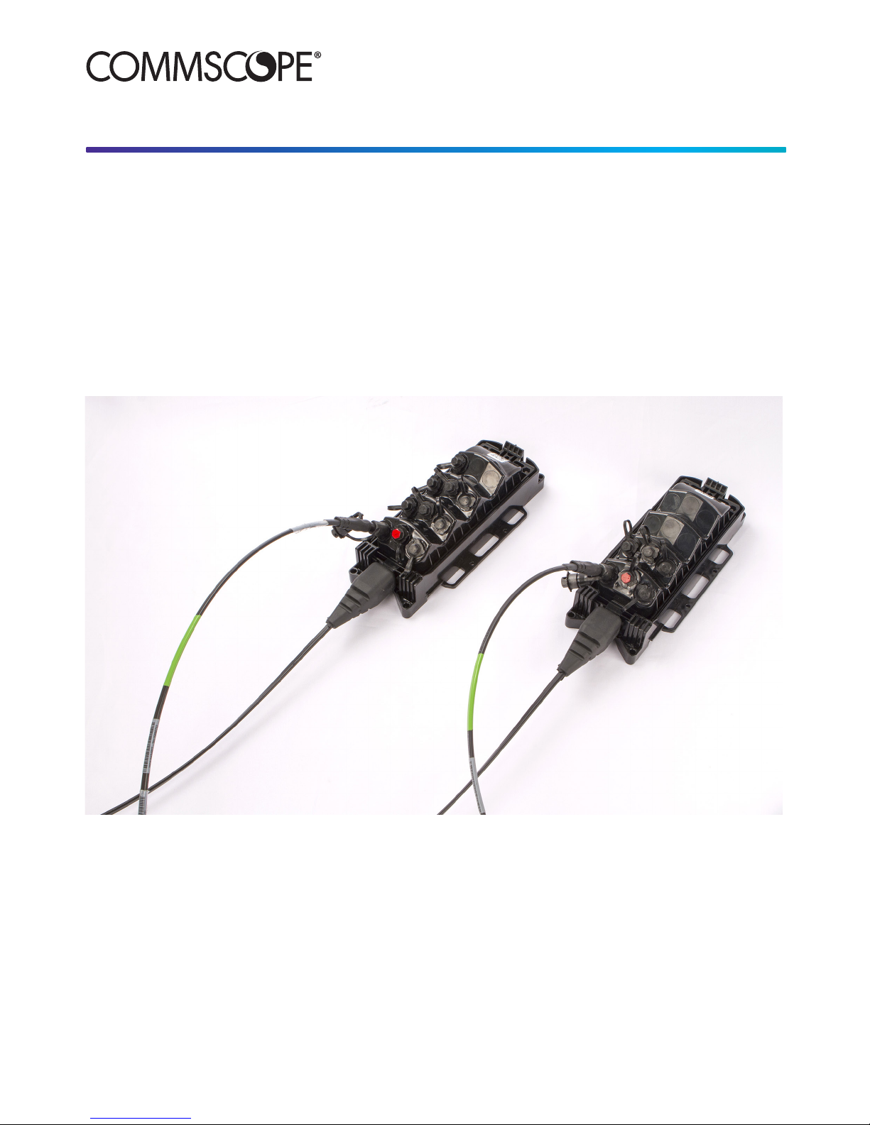
This installation instruction describes the installation of the ber indexing terminal of both housings, the DLX connector
housing and the full size hardened connector housing, and their different applications: the standard indexing terminal
with splitter (1:4 or 1:8), the indexing only terminal, the branch terminal and the multi-use terminal.
The instruction will explain how to handle the stubbed cable, how to mount the terminal in different situations (hand
hole, pedestal, pole and aerial), how to connect and maintain the different connector types (DLX, full size hardened
connector and HMFOC) and how to test the installed chain of terminals.
Page 2

Page 2 of 29
© 2017 CommScope, Inc. All Rights Reserved
2. General safety precautions
2.1. Fiber optic cables may be damaged if bent or
curved to a radius that is less than the recommended
minimum bend radius. Always observe the recommended
bend radius limit when installing ber optic cables and
patch cords.
2.2. Exposure to laser radiation can seriously
damage the retina of the eye. Do not look into the ends of
any optical ber. Do not assume the laser power is turned
off or that the ber is disconnected at the other end.
3. List of acronyms and
abbreviations
MST Multiport Service Terminal
FTTX Fiber To The X
DLX Dual Locking Connector
HMFOC Hardened Multiber Optical Connector
MPO Multi-ber Push On
FDH Fiber Distribution Hub
UMB Universal Mounting Bracket
VAM Value Added Module
CO Central Ofce
VFL Visual Fault Locator
Lead a single chain of terminals
Upstream a position closer to the CO or head end
Downstream to a position closer to the end of a lead
1. About this installation instruction .......................................1
2. General safety precautions ..................................................2
3. List of acronyms and abbreviations ....................................2
4. Fiber indexing ........................................................................3
4.1. Fiber indexing building blocks .................................................3
4.2. Reverse feed ...........................................................................3
4.3. Fiber indexing technology .......................................................3
5. Fiber indexing terminal .........................................................4
5.1. Housings .................................................................................4
5.2. Congurations .........................................................................5
5.3. Cable stub ...............................................................................8
5.4. Universal Mounting bracket .....................................................9
5.5. Accessories .............................................................................9
6. Network design with the indexing terminals ......................9
7. Installation .............................................................................9
7.1. Tools and materials required ...................................................9
7.2. Installation overview ..............................................................10
7.3. Unpacking and inspection .....................................................10
8. Cable handling recommendations .....................................11
9. Mounting the terminal .........................................................12
9.1. Disconnect the terminal from its UMB ...................................12
9.2. Hand-Hole mounting .............................................................12
9.3. Pedestal mounting.................................................................13
9.4. Pole-mounting .......................................................................14
9.5. Strand-mounting ....................................................................15
9.6. Installing the terminal in its UMB ...........................................15
10. Link installation (HMFOC) ..................................................16
10.1. Connector components .........................................................16
10.2. Adapter components .............................................................16
10.3. HMFOC specications ...........................................................16
10.4. Connecting the HMFOC (making the link installation)...........16
10.5. Disconnecting the HMFOC ...................................................17
11. DLX connector installation .................................................18
11.1. Connector components .........................................................18
11.2. Adapter components ............................................................18
11.3. DLX specications .................................................................19
11.4. Connecting the drop cable to the indexing terminal
(DLX connector housing) adapter port ..................................19
11.5. Disconnecting the drop cable from the indexing terminal
(DLX connector housing) adapter port ..................................20
12. Full size hardened connector installation .........................21
12.1. Connector components .........................................................21
12.2. Adapter components .............................................................21
12.3. Full size hardened connector specications ........................21
12.4. Connecting the drop cable to the indexing terminal (full size
hardened connector housing) adapter port ..........................22
12.5. Disconnecting the drop cable from the indexing terminal
(full size hardened connector housing) adapter port .............23
12.6. Applying O-ring lubricant .......................................................23
13. Testing ..................................................................................23
13.1. Conformance Testing ............................................................23
13.2. Bench Testing ........................................................................25
13.3. Trouble Shooting ...................................................................25
13.4. Restoral .................................................................................26
13.5. Appendix ...............................................................................26
14. Maintenance .........................................................................27
14.1. HMFOC cleaning ...................................................................27
14.2. Cleaning DLX connector and adapter ...................................27
14.3. Cleaning full size hardened connector and adapter ..............28
15. Trademarks ..........................................................................29
16. Contact information ............................................................29
Contents
Page 3
Page 3 of 29
© 2017 CommScope, Inc. All Rights Reserved
4. Fiber indexing
4.1. Fiber indexing building blocks
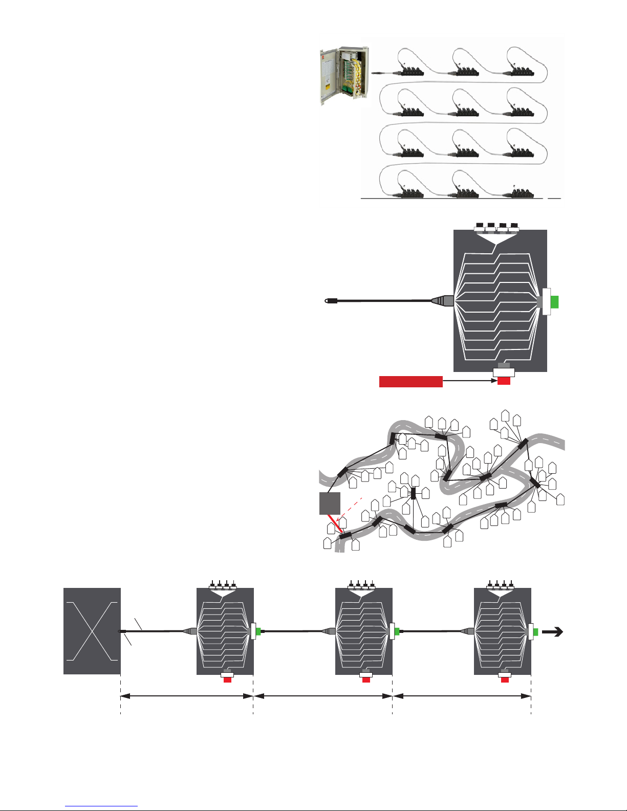
CommScope’s ber indexing system consists of terminals
and connectorized 12 strand ber cables using hardened
connectivity. It allows to build the FTTX network in the
outside plant environment faster, with plug and play
installation.
The exact same components (ber indexing terminal
and the corresponding drops to the homes) are installed
between a ber distribution hub (FDH) and subscribers
(homes) in a daisy chain architecture. Several daisy
chains are connected to the hub. Each chain consist of
up to 12 ber indexing terminals and d istributes services
to up to 96 subscribers (homes). Drop cable assemblies
transport the optical signal from the ber indexing
terminal to the home.
4.2. Reverse feed
When a second cable is connected from the hub (FDH) to
the last terminal , the signal runs “backwards” toward the
rst terminal. This makes additional bers available that
can be used to add subscribers or roll out new services.
More information on how to make this installation, can be
obtained in section 7.2.5.
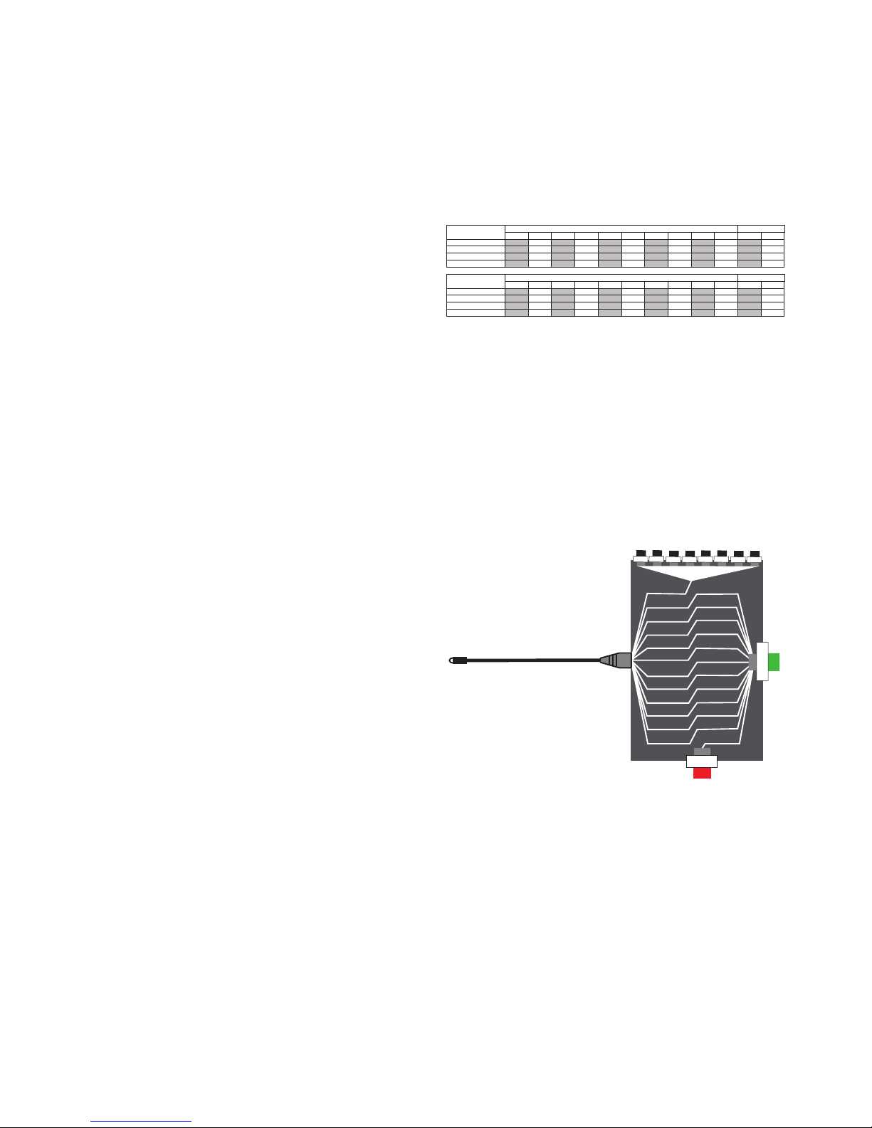
4.3. Fiber indexing technology
Indexing refers to the shifting of a ber’s position - from
one multi-ber connector to the other - within each
terminal.
• The process begins with a 12 ber cable from the
ber distribution hub (FDH) entering the rst ber
indexing terminal.
• Inside the terminal, the bers divide and the signal on
the ber on the rst position is routed to a splitter (1:4
or 1:8) for servicing local customers.
• All other bers are indexed - advanced one position
in the order - so that the number 2 ber shifts to
the number 1 position, ready to be routed to the
subscribers at the next terminal.
• The bers are re-combined using a 12 ber HMFOC.
The last ber position of the 12 ber HMFOC
becomes accessible via the reverse path optical port.
DROP
DROP
DROP
DROP
HMFOC
DROP
Fiber 1
1
2
2
3
3
4
4
5
5
6
6
7
7
8
8
9
9
10
10
11
11
12
12
REVERSE FEED
DROP
DROP
DROP
DROP
DROP
Fiber 1
1
2
2
3
3
4
4
5
5
6
6
7
7
8
8
9
9
10
10
11
11
12
12
DROP
DROP
DROP
DROP
DROP
Fiber 1
1
2
2
3
3
4
4
5
5
6
6
7
7
8
8
9
9
10
10
11
11
12
12
DROP
DROP
DROP
DROP
HMFOC
DROP
Fiber 1
1
2
2
3
3
4
4
5
5
6
6
7
7
8
8
9
9
10
10
11
11
12
12
HMFOC
HMFOC
Fiber
Distribution
Hub
Indexing terminal Indexing terminal Indexing terminal
Hardened Multi Fiber
Connector (HMFOC)
12 fiber cable
basic building block:
connectorized cable and terminal
repeat repeat
HUB
6
8
5
4
3
2
1
9
10
11
7
12
Reverse feed
Page 4
Page 4 of 29
© 2017 CommScope, Inc. All Rights Reserved
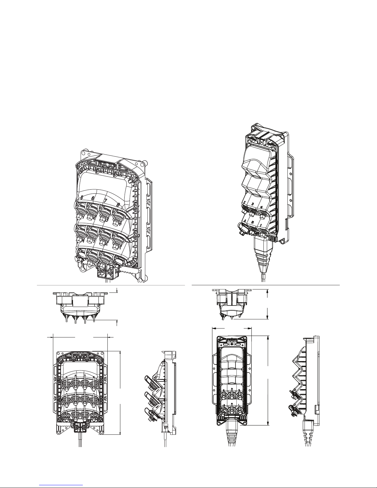
5.1.2. DLX connector housing
This housing contains DLX adapters. (See chapter 11
for installation guidelines) for the single-ber drops and
an HMFOC adapter (male) to connect the terminal to the
next terminal. (See chapter 10 for installation guidelines).
The input for these adapters is a 12 ber cable that
enters the terminal through a sealed opening located at
the bottom of the terminal. The stub cable is terminated
with an HMFOC connector (female). The terminal ships
with its UMB.
This housing is also used for the branch terminal
conguration that doesn’t contain single-ber drops. Only
2 HMFOC ports are available in this model (see section
5.2.4)
5. Fiber indexing terminal
All indexing terminals have a hardened, weather
resistant plastic housing. The housing type depends on
the adapter type of the single-ber drop port, either full
size hardened or DLX. Both housing types use HMFOC
adapter(s) for the multi-ber connection.
5.1. Housings
5.1.1. Full size hardened connector housing
This housing contains full size hardened adapters (see
chapter 12 for installation guidelines) for the single-
ber drops and an HMFOC adapter (male) to connect
the terminal to the next terminal. (See chapter 10 for
installation guidelines). The input for these adapters is a
12 ber cable that enters the terminal through a sealed
opening located at the bottom of the terminal. The stub
cable is terminated with an HMFOC connector (female).
The terminal ships with its UMB.
[3,69 IN]
9,38 CM
[7,4 IN]
18,8 CM
[11,26 IN]
28,6 CM
[11,69 IN]
29,69 CM
[5,13 IN]
13,03 CM
[3,91 IN]
9,92 CM
Page 5
Page 5 of 29
© 2017 CommScope, Inc. All Rights Reserved
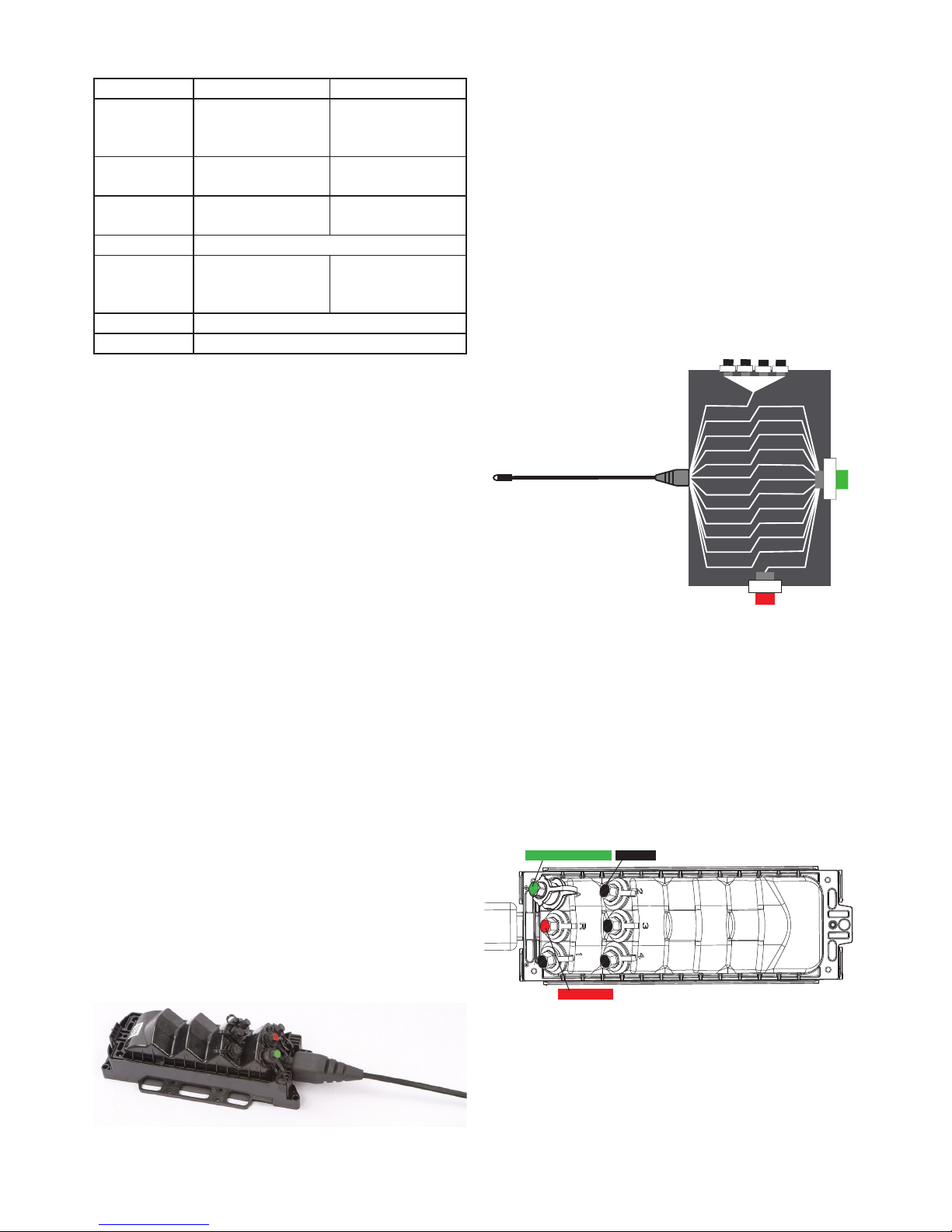
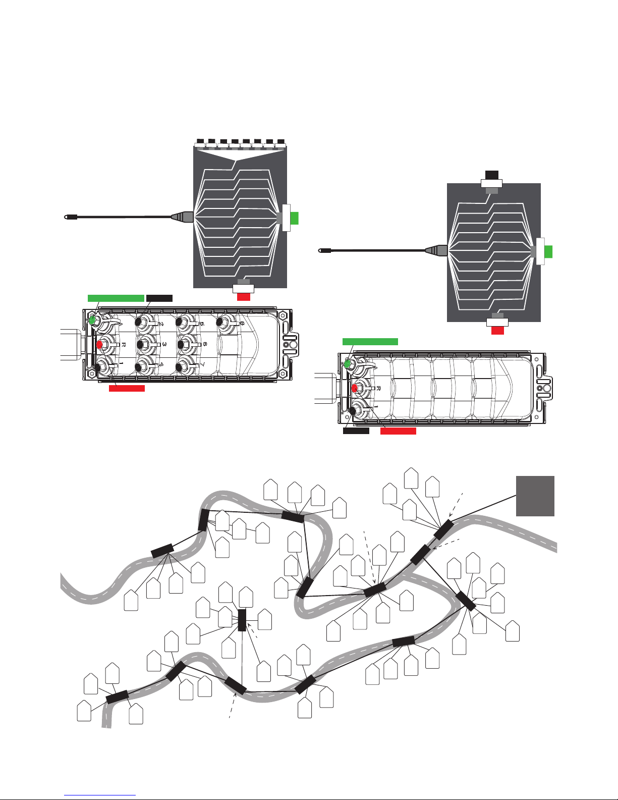
5.2.2. Standard indexing terminal 1:4 splitter with
reverse port
In this conguration, the terminal will drop the rst ber
from the incoming 12 ber strand. This ber will be
routed to an integrated 1:4 splitter. The outputs of this
splitter are DLX adapters or full size hardened adapters
(depending on the housing type). The others 11 bers
from the incoming 12 ber strand cable will proceed
unsplit and be terminated on a HMFOC adapter port,
together with the ber coming from the reverse port.
The ber coming from the reverse port will take # 12 of
the outgoing 12 ber HMFOC, the incoming ber # 2 will
take # 1 of this outgoing 12 ber HMFOC.
The HMFOC adapter port is colored green and indicated
with an ‘A’ on the terminal. The reverse port is colored red
and indicated with a ‘R’ and the terminal.
Image below shows the schematics inside the terminal.
The 12 ber strand cable terminated on a female HMFOC
of this terminal is connected to the green HMFOC
adapter port of its up-stream terminal (to the FDH in case
of the rst terminal of the chain), a forward feed path is
created. 4 subscribers (homes) can be fed around this
indexed terminal by connecting a connectorized drop
cable (DLX or full size hardened) to one of the 4 black
dust cap adapter ports.
Up to 12 indexed terminals can be connected one after
the other (link installation).
Image below shows the available ports and color code of
the adapters of this terminal conguration:
DROP
DROP
DROP
DROP
HMFOC
DROP
Fiber 1
1
2
2
3
3
4
4
5
5
6
6
7
7
8
8
9
9
10
10
11
11
12
12
HMFOC Adapter port Drop port
Reverse port
5.1.3. Specications
PARAMETER SPECIFICATION US SPECIFICATION IEC
Environmental GR-771-CORE,
and GR-3120-CORE
(HMFOC)
IEC 61753-1 Ed2
CAT A&G
Operation
Temperature
–40ºF (± 3.6º) to 150ºF
(± 3.6º)
–40ºC (± 2º) to 65ºC
(± 2º)
Installation
temperature
23°F to 113°F - 5°C to 45°C
Humidity 0% to 100%RH
Water resistance NEMA 6
(10-foot water head for
7 days without leakage)
IEC 60529-IP 68 (till 3
meters for 7 days)
Flammability UL94-5VA
Color Black
Both housings are designed to meet aerial and pedestal
conditions. For hand-hole application, the housings are
designed to meet the conditions for hand-holes located
up to 3 meters (10 feet) under ground.
5.2. Congurations
To build the network, each housing type is available in 4
congurations:
• Standard indexing terminal with 1:4 splitter
• Standard indexing terminal with 1:8 splitter
• Indexing only
• Branch terminal
5.2.1. Color code (ports)
To ensure correct installation, the terminal ports are colorcoded:
BLACK forward feed
DLX or full size hardened connector
single-ber drop (split signal)
ORANGE forward feed
DLX or full size hardened connector
single-ber drop (unsplit signal)
RED reverse feed
DLX or full size hardened connector
single-ber drop or HMFOC
GREEN HMFOC
12 ber cable output to the next terminal
BLUE HMFOC-branching only
12 ber cable output that route a portion
of the 12 input bers to another terminal
Page 6
Page 6 of 29
© 2017 CommScope, Inc. All Rights Reserved
5.2.4. Indexing only terminal with reverse port
The indexing terminal is also available without an
integrated splitter. In this case the unsplit signal of the
rst ber of the incoming chain, goes to a single drop
(black dust cap). This single drop can be connected to a
more peripheral terminal where splicing and or splitting
is performed. This topology enables a greater spatial
coverage though the possible number of drops remains
the same for each chain.
Images below shows the schematics inside the terminal
and the color code of the adapters of this terminal.
HMFOC
DROP
Fiber 1
1
2
2
3
3
4
4
5
5
6
6
7
7
8
8
9
9
10
10
11
11
12
12
DROP
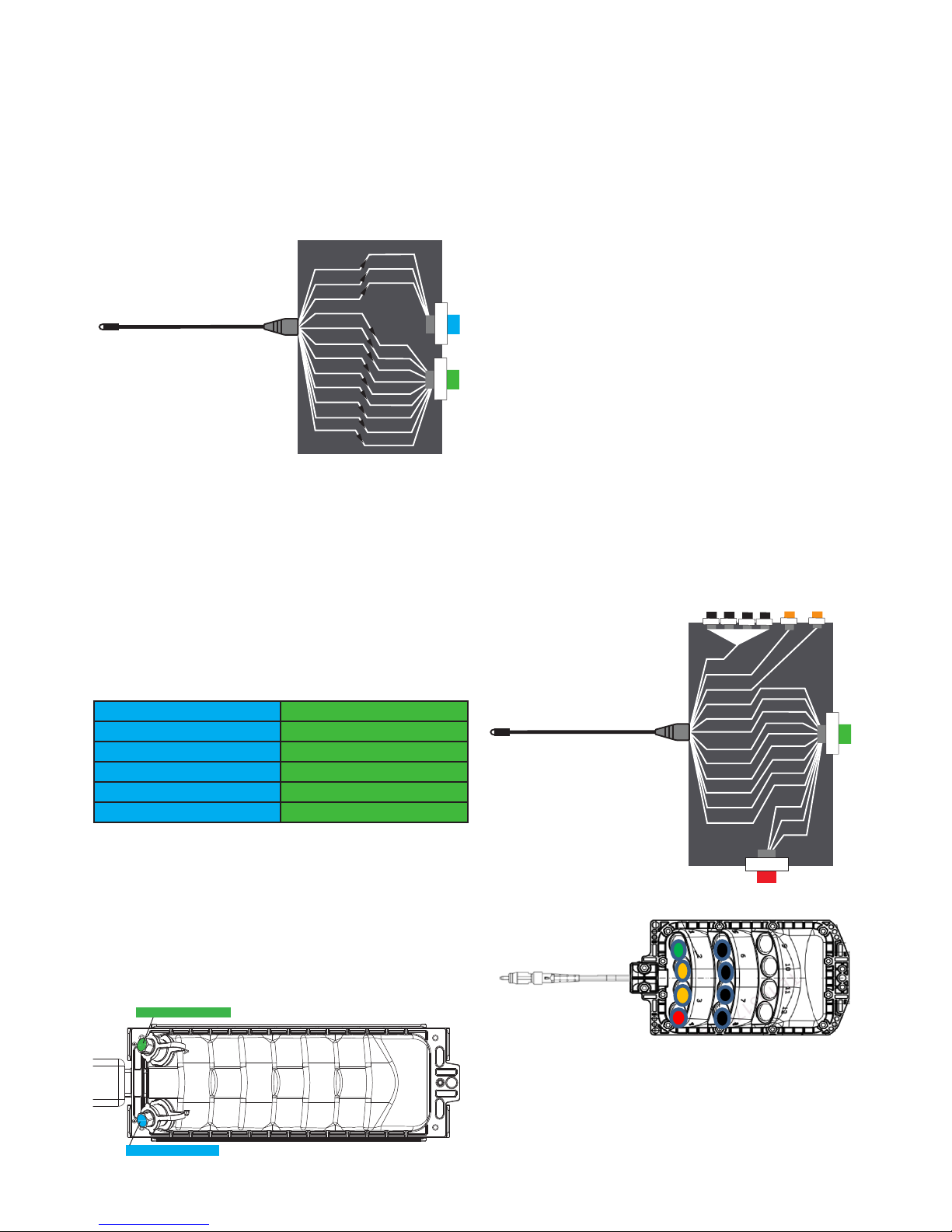
5.2.3. Standard indexing terminal 1:8 splitter with
reverse port
If there are more subscribers (homes) around the
indexing terminal to feed, the terminal can have a 1:8
splitter instead of a 1:4 as described in section 5.2.2.
8 homes can be fed (passed) from this terminal.
Images below shows the schematics inside the terminal
and the color code of the adapters of this terminal.
Image below illustrates the positions of the different
terminal congurations in the network:
DROP
DROP
DROP
DROP
DROP
DROP
DROP
DROP
HMFOC
DROP
Fiber 1
1
2
2
3
3
4
4
5
5
6
6
7
7
8
8
9
9
10
10
11
11
12
12
HMFOC Adapter port Drop port
Reverse port
HMFOC Adapter port
Drop port
Reverse port
HUB
A
B
1
8
2
3
4
5
6
9
10
11
7
12
INDEXING BRANCH
INDEXING 1:4
INDEXING 1:8
INDEXING ONLY
SPLITTER ONLY
Page 7
Page 7 of 29
© 2017 CommScope, Inc. All Rights Reserved
The daisy chaining installation can continue from each
HMFOC adapter port, but with a reduced chain in either
direction as dened by the ber branch quantity.
Although this terminal has no reverse feed adapter port,
the reverse feed functionality is still available in the
reduced chains.
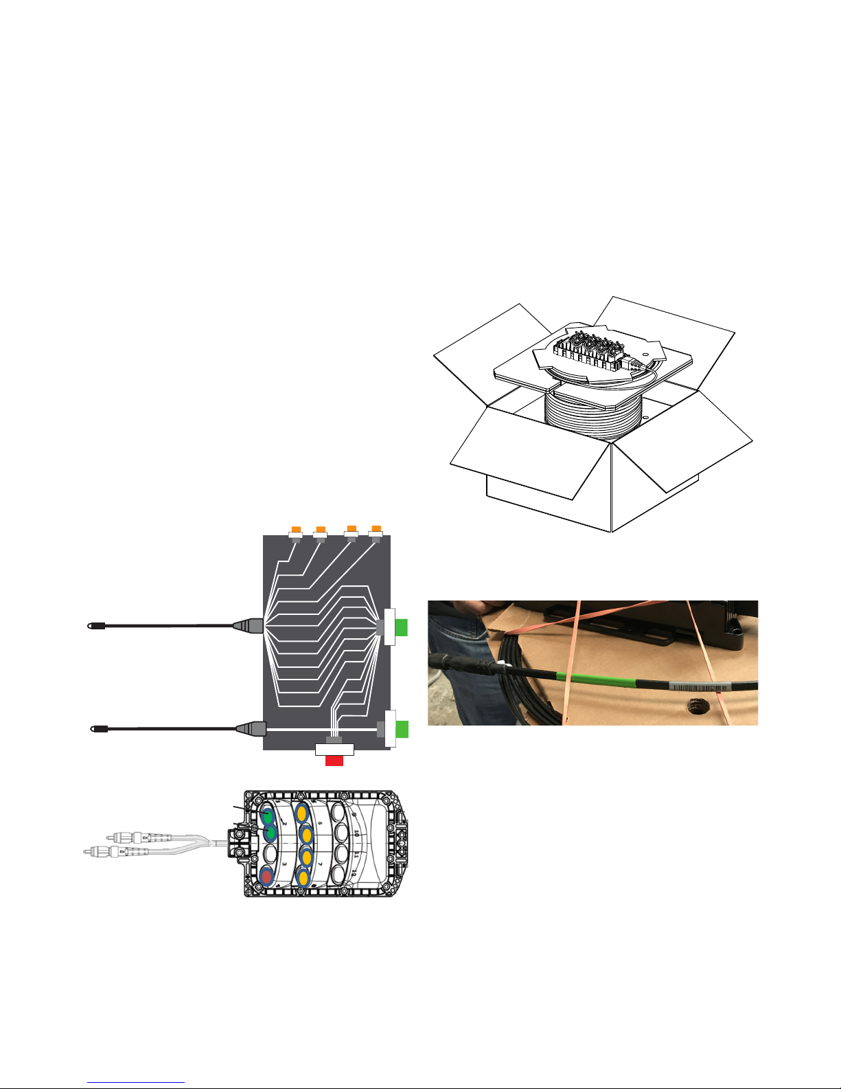
5.2.6. Multi-use
5.2.6.1. Internal splitter with pass-thru bers
Multi-use ber terminals are designed to deliver splitter
based services and/or traditional “unsplit” services. The
splitter (if present) is always connected to the rst ber of
the incoming 12 ber stand. The outputs of the splitter are
indicated with a black dust cap. Adapters with an orange
dust cap indicate a straight pass-thru ber. It is a ber
dropped of from the incoming 12 ber chain, but unsplit
(it is a regular ber coming from the hub).
Example below shows the rst ber dropped of routed
to an integrated 1:4 splitter and the second and the third
ber dropped of directly routed to the adapter port.
The other 9 bers from the incoming 12 ber strand
continue via the green HMFOC adapter port where ber
4 of the incoming strand will take in position 1 in the
adapter port. 3 bers from the red reverse port will take in
positions 10,11 and 12 in the green HMFOC port. In this
case the reverse port is also an HMFOC adapter port.
In this example, link installation decreases to 4 terminals
in a chain.
DROP
DROP
DROP
DROP
Fiber 1
1
2
2
3
1
4
3
5
4
6
6
5
7
7
8
8
9
9
10
10
11
11
12
12
DROP
DROP
HMFOC
HMFOC
5.2.5. Indexing branch terminal
The indexing branch terminal enables dividing the
incoming 12 bers into 2 HMFOC adapter ports. This
conguration provides more exibility in the distribution
network as greater spatial coverage area can be
achieved. Neither the reverse feed port nor the single
drop ports are included on an indexing branch terminal.
The image below shows the schematic inside the
terminal:
The rst bers from the incoming 12 ber tail are always
routed to the blue HMFOC connector, indicated with
letter B, the other bers are routed to the green HMFOC,
indicated with letter A.
The bers always take in the rst ber positions in the
multi ber connector. Image above illustrates the rst 3
bers from the incoming 12 ber tail (input) routed to the
rst 3 positions in the blue HMFOC connector, the last
9 bers from the incoming 12 ber tail routed to the rst
positions in the green HMFOC connector. The remaining
positions of the green and blue HMFOC are unused.
The Indexing branch terminal can be delivered with
following division of the incoming 12 bers.
B (blue) A (green)
1,2 3 to 12
1 to 3 4 to 12
1 to 4 5 to 12
1 to 5 6 to 12
1 to 6 7 to 12
The model number (catalogue number) indicates the
quantity of bers going to the blue HMFOC:
For example NDX-B3 indicates that the rst 3 bers
of the incoming 12 ber strand are routed to the blue
HMFOC and the last 9 bers are routed to the green
HMFOC taking in the rst positions (position 1-9) in the
connector.
The image below shows the color code and the letter
code of the 2 HMFOC adapter ports.
HMFOC
1
2
3
4
5
6
7
1
2
3
1
3
2
4
8
5
9
6
10
7
11
12
8
9
B
HMFOC
A
HMFOC Adapter port A
HMFOC Adapter port B
Page 8
Page 8 of 29
© 2017 CommScope, Inc. All Rights Reserved
5.3. Cable stub
5.3.1. Cable type and length
The cable stub on the terminal is an all-dielectric at drop
cable terminated with a female (non-pinned) HMFOC.
The cable outer dimensions are 8 x4.3 mm (0.31x0.17
inch).
Cable length that can be ordered, range from 3 to 609 m
(10 to 2000 feet). See ordering guide for details.
Terminals with cable stub lengths less than 30.5 m (100
feet) are shipped coiled. When the cable stub is 30.5 m
(100 feet) or longer, the terminal is shipped on a spool,
with the terminal secured on the spool ange as shown in
the image below:
A serial number label is applied on the cable
approximately 0.2 m (8 inch) from the connector body.
See image below.
5.2.6.2. 24 ber Indexing terminals
Twenty-four ber Indexing terminals are designed to
deliver bulk ber into a distribution area where split and
unsplit services are needed. On board splitters have been
removed in favor of external splitters. Fibers are allocated
into two groups. Fibers 1-12 are congured to the
standard indexing model. Fibers 13-24 are congured as
pure pass-thru without indexing. This segregation allows
for the express delivery of bers independent of indexing
architectures when necessary and replenishment of ber
when the indexing string becomes exhausted.
Example below shows the rst 4 bers dropped of. The
signal is unsplit. The ber in each of these drop off port is
a straight pass-thru ber. The dust cap is orange.
Fiber 5 of the incoming 12F strand takes in position 1 of
the outgoing HMFOC adapter port (A1). 4 bers of the
reverse port take in position 8,9,10, 11 and 12 in that
adapter port.
Indexing terminals exhaust themselves once 12 bers
have been allocated. This may happen in as few as three
links or as many as 12 links dependent on how the bers
are distributed along the way. Twenty-four ber terminals
have the capacity to replenish an indexing string by
harnessing the express group on the “A2” port. This is
achieved by attaching the next indexing terminal to the
“A2” port. If the next terminal is a twenty-four ber
terminal then the tail connectors will be swapped (e.g.
“a1” tail connector to “A2” port and “a2” tail connector to
“A1” port).
A1
A2
Fiber 1
1
2
2
3
1
4
3
5
4
6
6
5
7
7
8
8
9
9
10
10
11
11
12
12
DROP
DROP
DROP
DROP
HMFOC
12F
HMFOC
A2
HMFOC
A1
a1, Fiber 1-12
a2, Fiber 13-24
Page 9
Page 9 of 29
© 2017 CommScope, Inc. All Rights Reserved
5.5.5. Cleaning kit HMFOC
To clean the HMFOC adapter and connector, a US
Conec HMFOC connector cleaning tool (PN 15639)
can be ordered at US Conec.
6. Network design with the
indexing terminals
The different congurations of the indexing terminals
can be combined to provide all the necessary exibility
and maximize the capacity of the distribution network.
First splitting level occurs typically in a Mini-FDH 3000
with 96 ports or an OSP closure (FOSC/FIST/TENIO)
with additional HMFOC connectors. The second splitting
level occurs within the indexing terminals, the different
congurations are explained in section 5.2.
Indexing chains always start with terminal one and build
outward in procession to a value no greater than twelve.
Indexing chains always provide the next ber to the
next terminal (i.e. Terminal 1 will use ber 1 within the
“chained” assembly).
In order to build an optimized network utilizing indexing
terminals, the following items should be considered prior
to beginning the network design:
• Locate and identify all Customers to have an
overview of all area to be covered/deployed.
• Clear up all drawing nomenclature: hand holes,
poles, ducts, terminals, etc.
• Identify feeder ber cables availability. If available,
dene the ber count & type of cables.
• Locate nearest CO, Node or HUB to determine the
maximum distance allowed within the optical budget
• Take into consideration, drop cable distances/routes
• Identify any network deployment restriction: Poles,
aerial capacity, underground ducts
• Discuss the best location for Indexing Terminals
(aerial, pole, wall, manhole)
• Consider the maximum number of services per
indexing terminal
• Split ratio: Specied by project
7. Installation
7.1. Tools and materials required
The following basic tools, auxiliary equipment, and
materials are required for the installation of the indexing
terminals:
• Vertical roller reel (if the terminal is mounted on a
cable spool)
• 216B key tool (used to open optical port dust cap)
• Hardened connector/adapter cleaning kit
(FHD-ACC-CLNKIT1)
• US Conec HMFOC connector cleaning tool (PN
15639)
• Utility knife
• Cable pulling equipment
• Appropriate fasteners to mount the UMB and tools to
install the fasteners
• “P” clamps for self supporting aerial installations.
Cable routing rings or fasteners (see local practices).
Cable can be lashed for messenger applications.
5.4. Universal Mounting bracket
Each terminal is supplied with the Universal Mounting
Bracket (UMB) which is used for mounting the ber
indexing terminal. The UMB may be attached to various
mounting surfaces using a variety of fasteners as will be
explained in section 9.
The UMB is housing specic and exist for the full size
hardened housing as well as for the DLX housing.
5.5. Accessories
5.5.1. Strand mounting kit
To secure the terminal to a strand, a strand-mount
bracket kit is available and must be ordered separately.
Refer to Universal Mounting bracket Strand-Mount
Installation InstructionADCP-96-124 for the installation
procedure. Section 9.5 provides some info about how to
use this strand mounting kit.
5.5.2. NDX-POLE-BRKT
To store excess cable in aerial applications, an NDXPOLE-BRKT kit is available and must be ordered
separately. If using the full size hardened connector
housing, an adapter bracket must also be ordered when
using the excess cable storage bracket (part number
NDX-4X3-ADPT-BRKT).
The bracket is secured with 1/4 inch thread size hardware
to a pole. Excess cable can be looped around the
bracket. When all excess cable is stored, the terminal
with its UMB can be slided in an upward direction into the
NDX-pole bracket.
5.5.3. 216B key tool
The opening to each optical port is sealed with a
threaded dust cap that prevents the entry of dirt and
moisture. A standard 216B security tool can be ordered to
remove the dust cap.
5.5.4. Cleaning kit FHD-ACC-CLNKIT1
To clean the drop ports adapters and connectors (both full
size hardened and DLX), a cleaning kit can be ordered.
How to use this is explained in chapter 14 maintenance.
Page 10
Page 10 of 29
© 2017 CommScope, Inc. All Rights Reserved
7.3. Unpacking and inspection
Open the shipping carton(s) and carefully inspect the
terminal and the attached cable. If there are damages,
contact CommScope product support at:
http://www.commscope.com/SupportCenter.
With each terminal a test report (VAM/Splitter Module
Assembly Performance Sheet) of the optical ports is
delivered:
Insertion Loss (IL) as well as Return Loss (RL) are tested
on 2 different wavelengths before shipment. IL is the
insertion loss between the female (non-pinned) HMFOC
on the tail and the output ports. RL is the return loss on
the output ports itself.
For an indexing terminal with a 1:8 splitter, port 1 to 8 are
the results for the forward feed adapters (ports with black
dust cap indicated respectively with number 1 to 8). Port
9 to 19 are the results for the rst 11 individual bers in
the HMFOC adapter (green dust cap, indicated with A).
Port 20 is the test result for the reverse feed adapter (red
dust cap). Image below illustrates the port numbering in
case of a 1:8 splitter.
For an indexing terminal with a 1:4 splitter, port 1 to 4 are
the results for the forward feed adapters (ports with black
dust cap indicated respectively with number 1 to 4). Port
5 to 15 are the results for the rst 11 individual bers in
the HMFOC adapter (green dust cap, indicated with A).
Port 16 is the test result for the reverse feed adapter (red
dust cap).
VAM/Splitter Module Assembly Performance Sheet
Catalog Number: NDX-10BTM0U-A0010F
Serial Number: 71171926081
Test Port Summary
12345678910MaxMin
IL @ 1310nm 9.905 9.849 9.863 9.509 9.571 9.629 9.575 9.496 0.207 0.204 9.905 0.204
RL @ 1310nm > 65 > 65 > 65 > 65 > 65 > 65 > 65 > 65 > 65 > 65 > 65 > 65
IL @ 1550nm 9.858 9.758 9.715 9.47 9.515 9.603 9.529 9.645 0.128 0.196 9.858 0.128
RL @ 1550nm > 65 > 65 > 65 > 65 > 65 > 65 > 65 > 65 > 65 > 65 > 65 > 65
Test Port Summary
11 12 13 14 15 16 17 18 19 20 Max Min
IL @ 1310nm 0.367 0.285 0.131 0.113 0.233 0.038 0.31 0.10 0.254 0.632 0.632 0.038
RL @ 1310nm > 65 > 65 > 65 > 65 > 65 > 65 > 65 > 65 > 65 > 65 > 65 > 65
IL @ 1550nm 0.354 0.222 0.091 0.092 0.154 0.025 0.253 0.089 0.209 0.481 0.481 0.025
RL @ 1550nm > 65 > 65 > 65 > 65 > 65 > 65 > 65 > 65 > 65 > 65 > 65 > 65
DROP
DROP
DROP
DROP
DROP
DROP
DROP
DROP
HMFOC
DROP
spliced
9
1
8
10
11
12
13
14
15
16
17
18
19
20
12F
Note: If using an enclosure such as a hand-hole or
pedestal, refer to the instructions provided with the
enclosure for any additional tools or equipment required.
7.2. Installation overview
To install the indexing terminals in the network and to
build the indexing network, following main tasks must be
perfomed:
1. Mounting the terminal (refer to section 9)
The terminal must be mounted on or within a suitable
support base or enclosure. The UMB allows the
terminal to be mounted in a variety of applications
including the following:
• Hand-Hole (below ground)
• Pole-Mount (aerial)
• Strand-Mount (aerial)
• Pedestal (at nal grade)
2. Link installation (installing the HMFOC)
The terminals connect to one another via a Hardened
Multi-Fiber Optic Connector (HMFOC). The nonpinned tail connector (HMFOC) is routed to the up-
stream component like an FDH or a previous terminal
for termination. The “green” capped MPO (pinned,
male) in the body of the terminal housing receives the
downstream tail connector (non-pinned,female).
For the indexing branch terminal, the blue adapter
port is a capped MPO (pinned) which can receive the
downstream tail from another chain.
Refer to section 8 for cable handling recommen-
dations and refer to section 10 for making the
HMFOC connection.
3. Testing the indexing chain (refer to section 13)
After installing the indexing chain, the signal on the
drops should be tested to ensure a correct installation
of the chain.
4. Drop cable installation and connection
After the indexing chain is set up, the single drop
connection can be made. Follow local practice
for pulling and installing drop cables. Refer to the
instructions provided with the mounting system for
drop cable entry and routing. Service is enabled by
connecting the drop cable connectors to the black
dust cap adapter ports on the terminal (see section
11 and 12).
In the Indexing Only conguration, a splitter only
terminal can be installed to the single black dust cap
adapter port. The subscribers will be connected to
this splitter only terminal.
5. Reverse feed installation
If all indexing terminals are installed, a FO cable with
HMFOC connectors at both ends can be connected
to the green dust cap adapter port of the last terminal
and to a 2nd HMFOC connector of the FDH. Now,
all RED ports from all Indexing terminals can be
connected to subscribers. The red adapter port is a
DLX or full size hardened connector, depending on
the housing. For installation, refer to section 11 or
12).
6. Maintenance
Maintenance for the indexing terminal is limited
to cleaning the hardened adapters as needed to
maintain optimal performance. Refer to section14.
Page 11

Page 11 of 29
© 2017 CommScope, Inc. All Rights Reserved
To relieve strain on the HMFOC connection,
CommScope recommends component coupling.
Component coupling in optical cables is important
to harmonizing the movement of the various cable
components created by stresses during installation,
through thermal cycling and environmental loading.
Input: Loop the cable tail before entering the upstream
terminal. Make 5 loops with a diameter of 152.4 mm (6
inch).
Output: Also on the output component coupling is
recommended, looping the cable 5 ½ loops (with
diameter 152.4 mm (6 inch)) adequately enhances the
coupling to prevent buffer tube movement.
Note: For applications where the cable is pulled, remove
the coupling coils and reinstall when cable pull is
completed.
Overlength:
Always store overlength near the terminal where the
cable leaves the terminal. For pole mounting the NDX-
pole-BRT bracket can be used.
Cable pay off:
1. Determine the terminal’s nal location. Mount the spool
on a vertical arbor on that location and pull the tail to the
upstream network element (hub or terminal). Maximum
pulling force 444.8 N (100 lbs).
2. Secure the cable at the location of the upstream
network element (for example with a P-clamp attached to
a D-ring in aerial application).
The cable length from this securing point to the connector
should be long enough to make the HMFOC link
installation with correct cable bend and 5 loops to relieve
strain on the connection.
3. Make the link installation (chapter 10) to the upstream
network element and go back to the terminal.
4. Mount the UMB or NDX-pole-BRKT and secure the
cable (for example with a P-clamp attached to a D-ring in
aerial applications).
Input
5 loops
Output
5
1/2
loops
8. Cable handling
recommendations
Each terminal is equipped with an optical cable.
Depending on the length of the cable, the dielectric cable
may be coiled up and placed in a box or it may be coiled
on a spool.
Coiled Cable Handling: Leave the terminal on top and in
the center of the coil. Locate the free end of the cable and
then carefully uncoil the cable from around the terminal.
Spooled Cable Handling: If the dielectric cable is coiled
on a spool, remove the spool from the box. Leave the
terminal on top of the spool and place the spool on a
vertical arbor. Locate the free end of the cable. Carefully
pull the cable away from the spool allowing the spool
assembly to rotate about the vertical arbor.
Cable Bend Radius Limits: Take care to observe the
recommended minimum bend radius limits for the cable.
Always maintain a minimum bend radius of 76.2 mm (3
inch).
Pulling the cable: When pulling the cable into place,
do not exceed a pulling force of 444.8 N (100 lbs) on
the optical cable. Pulling on the cable should be done
through the pulling cap, see picture below:
When connector is mated – in service, pulling force is
max 111.2 N (25 lbs).
Span rating: the recommended span width is as
followed:
m ft
NESC Light load Destrict 122 400
NESC Medium load Destrict 76 250
NESC Heavy load Destrict 46 150
Page 12

Page 12 of 29
© 2017 CommScope, Inc. All Rights Reserved
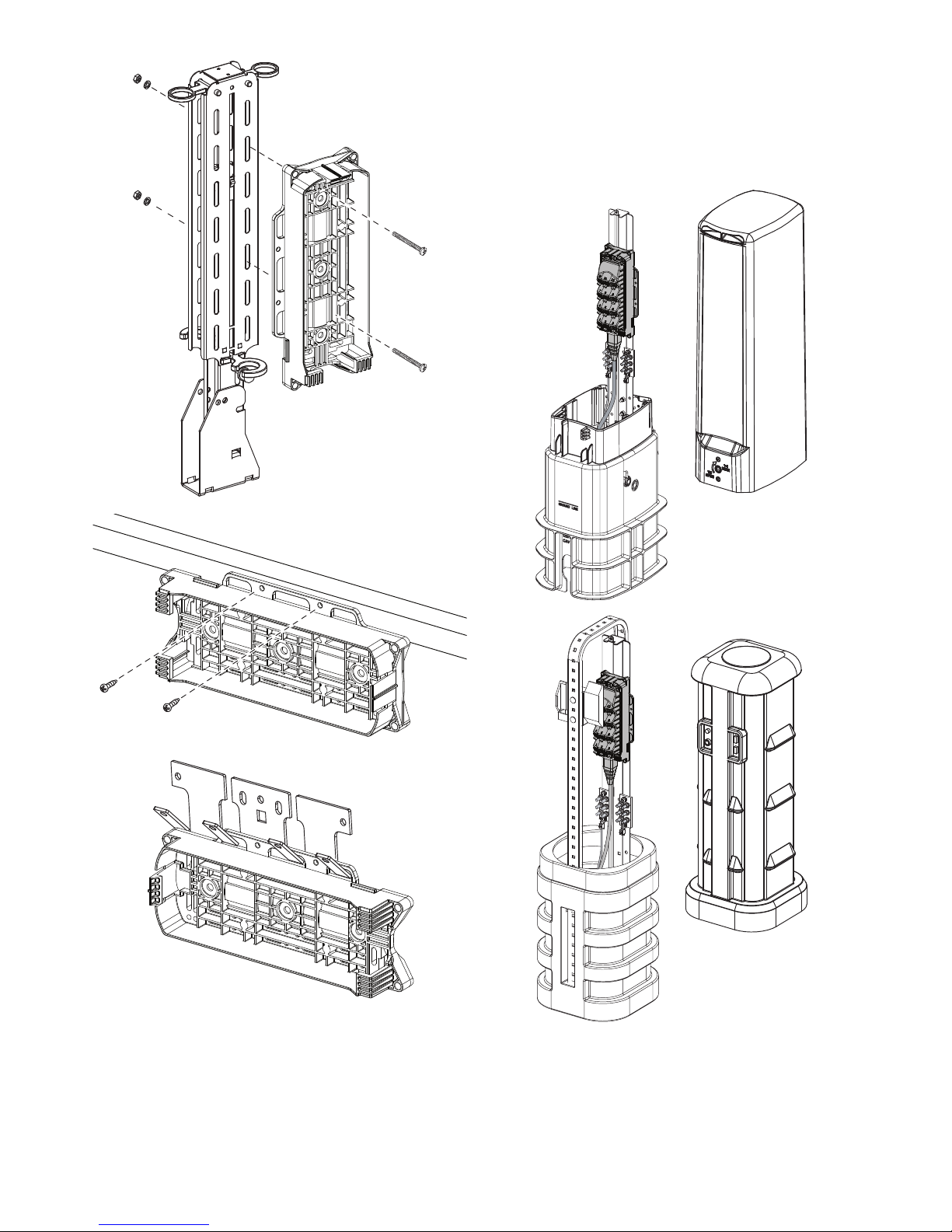
9.2. Hand-Hole mounting
Hand-Hole Mounting (below ground) – A hand-hole
enclosure (examples shown in Figure below) is an OSP
below-ground mounting system that may be used for any
indexing terminal or other similar products. When
installed, the top of the hand-hole enclosure is ush with
the top of the ground. Hand-hole enclosures consist of a
base unit and a top cover. The base unit mounts in the
ground. Cables and conduit enter the base unit from the
bottom.
CARSON
INDUSTRIES
®
CHANNELL
®
5. Store overlength near the terminal where the cable
leaves the terminal. For pole mounting the NDX bracket
can be used.
Note: The reverse option (cable spooled in opposite
way to pay off the cable in the reverse direction - from
upstream component to terminals nal position) is
available.
9. Mounting the terminal
9.1. Disconnect the terminal from its
UMB
To install the terminal in several situations, the terminal is
supplied with its UMB (universal mounting bracket). The
UMB can be attached to various mounting surfaces using
a variety of fasteners. Multiple holes and slots are
provided in the UMB to accommodate these variety of
fasteners. To reach these holes and slots, the terminal
should be disconnected from its UMB. This can be done
by lifting the snap t.
Release the terminal and move it slightly upwards. Now
the cable end can be taken out of the bracket:
Page 13
Page 13 of 29
© 2017 CommScope, Inc. All Rights Reserved
9.3. Pedestal mounting
Pedestal Mounting (at nal grade) – Pedestal enclosures
(examples shown below) may be used for mounting the
indexing terminal at ground level. Pedestal enclosures
consist of a base assembly and a top cover. The base
assembly mounts partly in the ground. Cables and
conduit enter the base assembly from the bottom.
7-INCH PROFORM
®
6- OR 8-INCH
CHANNELL
®
HAND-HOLE SWING
ARM MOUNT
#10 X 2 INCH
SCREWS,
WASHERS,
NUTS
HAND-HOLE
LEDGE MOUNT
#10 X 1 INCH
SELF TAPPING
SCREWS
HAND-HOLE
HANGER MOUNT
Page 14

Page 14 of 29
© 2017 CommScope, Inc. All Rights Reserved
An example to attach the UMB to the pedestal
infrastructure is shown below. Use local practice to mount
he UMB to the pedestal infrastructure.
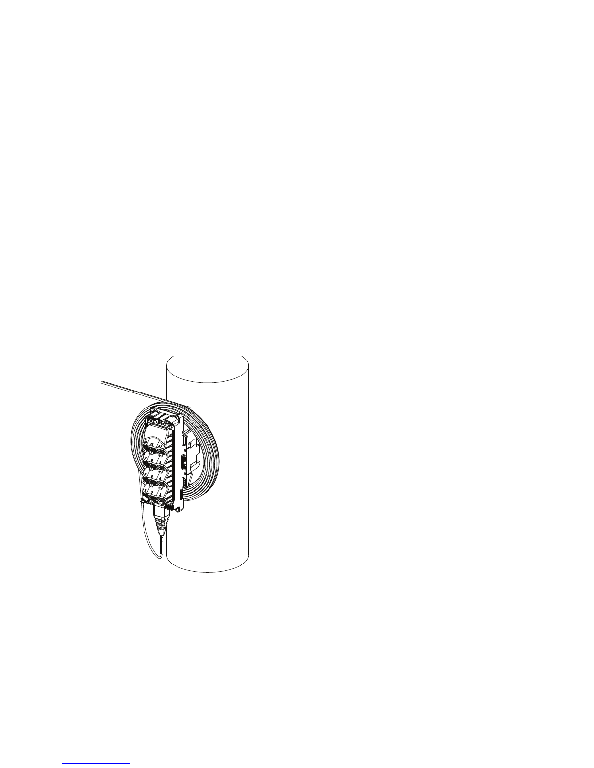
9.4. Pole-mounting
Pole-Mounting (aerial) – The indexing terminal may be
mounted on a utility pole. The UMB may be attached to
the pole with lag screws or construction screws.
Also metal straps can be used to mount the UMB to a
pole, for instance in case of a metal pole.
FLAT BRACKET MOUNT
#8-16 X 1/2 INCH
THREAD ROLLING
SCREWS FOR PLASTIC
CAPPED HOLES
METAL STRAPS
USE CENTER HOLES
WHEN SECURING UMB
WITH LAG SCREWS
1/4 X 1-1/2 INCH
LAG SCREWS
USE SIDE HOLES
WHEN SECURING
UMB WITH
CONSTRUCTION
SCREWS
#10 X 1 INCH SELF
TAPPING SCREWS
Page 15

Page 15 of 29
© 2017 CommScope, Inc. All Rights Reserved
Or alternatively, cable straps can be used to mount the
UMB to a strand
9.6. Installing the terminal in its UMB
After the UMB is mounted, install the indexing terminal in
the UMB as shown in Figure 11. Insert the cable end of
the terminal into the UMB rst and then push the front of
the terminal into the UMB until the latch snaps closed.
1
2
2. PUSH ON FRONT OF MST
UNTIL LATCH SNAPS SHUT
1. INSERT CABLE END OF
MST INTO THE UMB
9.5. Strand-mounting
Strand-mounting (aerial) – A strand-mount bracket kit is
available for aerial mounting the indexing terminal from
an overhead strand as shown. The brackets mount on the
UMB and are then clamped to the strand.
Refer to Universal Mounting bracket Strand-Mount
Installation Instruction ADCP-96-124 for the installation
procedure.
.
1/4-20
NYLON NUT
(2 PLACES)
10-24
NYLON NUT
(4 PLACES)
1/4-20 x 1-1/4 IN.
CARRIAGE BOLT
(2 PLACES)
10-24 x 1 IN.
CARRIAGE BOLT
(4 PLACES)
STRAND-MOUNTING THE UMB
USING Deltec® CABLE STRAPS
Page 16
Page 16 of 29
© 2017 CommScope, Inc. All Rights Reserved
10.3. HMFOC specications
HMFOC Intermateability:
Compatible with Corning Optitip®
HMFOC:
Per GR 3120 and
IEC 61753-1 Ed2 CAT G (hardened connector)
10.4. Connecting the HMFOC (making the
link installation)
Danger: Exposure to laser radiation can seriously
damage the retina of the eye. Do not look into the ends
of any optical ber. Do not assume the laser power is
turned-off or that the ber is disconnected at the other
end.
10.4.1. Remove dust caps
10.4.1.1. Field personnel must take care when proceed
to remove dust caps at the HFMOC at the adapter plugs
or cables, to prevent contaminant particles entering to the
adapters or connector end-face.
10.4.1.2. Before removing dust cap, be sure to turn the
terminal to a position where adapters are protected (i.e.
for aerial application, adapters will face down), helping
to prevent any particle/ dust to fall down and contaminate the adapter. Before removing the terminals optical
port dust cap, clean any debris from around the indexing
terminal optical ports, preferably using compressed air,
to minimize the risk of introducing contaminants into the
optical port.
10.4.1.3. Use the 216B key tool (accessory) to unscrew
the dust cap from the indexing terminal optical port. This
is the green port, indicated with a letter A or the blue port,
indicated with letter B.
10.4.1.4. For the cables, before taking out the dust cap,
take in consideration all possible precaution to prevent
any particle to contact the end-face connector and, keep
the terminal with the adapters facing down to insert and
tight the drop cable. Before removing the cable’s con-
nector dust cap, clean any debris from around the cable
connector housing, preferably using compressed air, to
minimize the risk of introducing contaminants onto the
ferrule.
10. Link installation (HMFOC)
10.1. Connector components
The HMFOC connector at the end of the terminal’s tail
is a hardened 12 ber connector that can be used for
many applications. The primary application is to connect
indexing terminals in cascade or to connect an indexing
terminal to the Fiber Distribution Hub (FDH) or Closure, to
extend the distribution network.
The connector on the tail is the non-pinned female type.
The connector is protected by a dust cap. The O-ring on
the connector body provide a water tight seal when the
dust cap is in place. A pulling eye is provided in the end of
the dust cap for pulling the drop cable.
Do not exceed a pulling force of 444.8N (100 lbs) and
when connected, don’t exceed cable pull of 111.2 N
(25 lbs).
10.2. Adapter components
On the indexing terminal up to 2 ports are HMFOC
adapter ports, the green present on all the terminals and
the blue only present on the indexing branch terminal.
The connector inside the adapter is the pinned, male
type. It is a captured Multi-ber Push On (MPO)
connector.
Page 17
Page 17 of 29
© 2017 CommScope, Inc. All Rights Reserved
10.4.3.3. Thread the optical port dust cap into the drop
cable dust cap and tighten both dust caps nger tight.
This ensures that both dust caps will stay clean when not
in use.
10.5. Disconnecting the HMFOC
Danger: Exposure to laser radiation can seriously
damage the retina of the eye. Do not look into the ends
of any optical ber. Do not assume the laser power is
turned-off or that the ber is disconnected at the other
end.
10.5.1. Before removing the connector dust cap, clean
any debris from around the dust cap, preferably using
compressed air, to minimize the risk of contaminants be-
ing introduced onto the ferrule. Unscrew the optical port
dust cap from the drop cable dust cap.
10.5.2. Before removing the drop cable connector,
clean any debris from around the connector housing and
the terminal optical port, preferably using compressed air
to minimize contaminants from being introduce onto the
connector ferrule or into the optical port.
10.5.3. Unscrew the drop cable connector coupling nut
until the thread of the adapter port is completely free.
10.5.4. Grasp the connector and pull it straight out of
the adapter. The pull out force to remove the connector
should be minimum once the coupling nut is fully disengaged.
10.5.5. Uncouple the two dust caps.
10.5.6. Thread the optical port dust cap into the optical
port and tighten until nger tight.
10.5.7. Thread the drop cable connector coupling nut
into the drop cable dust cap and tighten until nger tight.
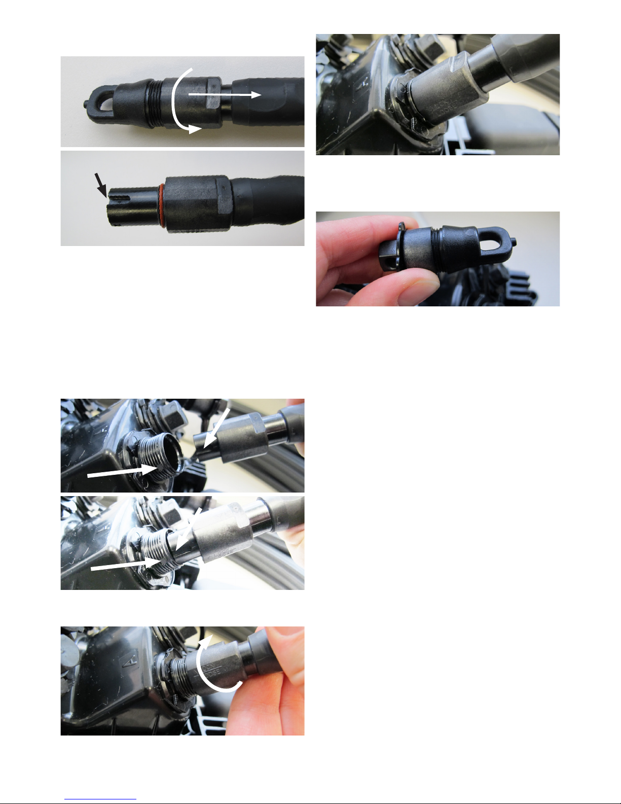
10.4.1.5. Unscrew the coupling nut from the cable
connector dust cap in the direction of the arrow.
10.4.2. HMFOC cleaning
Note: The connector and adapter come clean from the
factory and should not require additional cleaning before
the rst connection.
If cleaning is required before installing the connector,
follow procedure as described in section 14.1.
10.4.3. Install the connector
10.4.3.1. Find the alignment keys on the adapter port
(square notch in the thread area) and on the connector
(groove). And push the plug connector in the jack of the
adapter port until it seats.
10.4.3.2. Thread the cable connector’s coupling nut onto
the thread of the adapter port until it is nger tight.
Alignment indicator
(groove) on plug
Page 18

Page 18 of 29
© 2017 CommScope, Inc. All Rights Reserved
a standard SC connector using the DLX adapter (which
is the case in the indexing terminal drop adapter ports).
The connector design is based on standard SC single
mode ferrule and spring assembly in a miniature rugged
body. The connector is designed with a dual-locking
feature that includes a push-pull detent engagement and
twist-lock secure retention. The connector has a keying
feature to allow it to be fully seated in the adapter in only
one orientation, therefore, ensuring proper alignment and
mating of 8-degree APC ferrules.
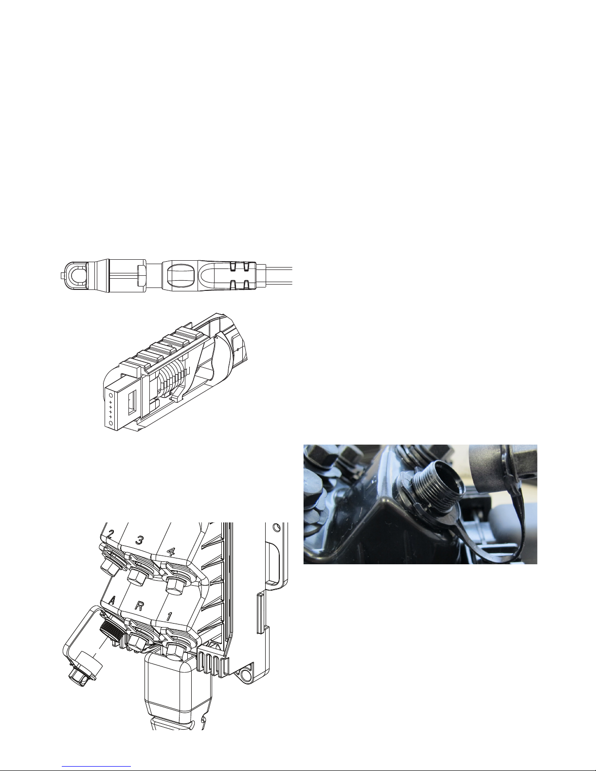
The basic components of the drop cable connector
are shown in gure below. The connector coupling nut
threads onto the dust cap. The O-ring on the connector
body provide a water tight seal when the dust cap is in
place. A pulling eye is provided in the end of the dust cap
for pulling the drop cable.
Do not exceed a pulling force of 444.8N (100 lbs) and
when connected, don’t exceed cable pull of 111.2 N
(25 lbs).
DUST CAP
O-RING
COUPLING NUT
CONNECTOR
BODY
11. DLX connector installation
Indexing terminals with the DLX connector housing use
DLX technology to connect a subscriber to the drop
adapter ports (black dust cap) and to connect the reverse
feed (red dust cap).
CommScope DLX hardened connectors and adapters
provide sealed environmental protection for the
subscriber drop cable connector, SC connector, and
adapter mounted within the indexing terminal optical
port. The following sections provide a description of
the connector and adapter components and provide
instructions for connecting or disconnecting the drop
cable to/from the optical ports. Also a section describing
the cleaning procedures for both connector and adapter
is integrated.
11.1. Connector components
The DLX connector can be mated with any SC adapter
to provide a low loss optical connection. It can also mate
11.2. Adapter components
The DLX adapter on the DLX connector housing
(black and red port) is a heavy duty plastic case
environmentally sealed for extreme weather conditions.
One side of the adapter receives the hardened DLX
connector and the other side is designed to receive a
standard SC connector plug. The SC side of the adapter
provides a rugged stationary SC receptacle per standard
industry specications. The DLX adapter has an opening
designed specically to receive the DLX connector and
to provide a sealing surface for the connector O-ring.
The adapter’s inner body holds two retainers and a split
sleeve using snap latches and provides the plug with both
push-pull and twist-lock engagement. The inner body also
contains detent latch and alignment features that guide
and hold the DLX connector inside the adapter.
The basic components of a typical indexing terminal
optical port hardened adapter are shown in Figure below.
The dust cap threads into the adapter housing. An O-ring
on the dust cap provides a water tight seal when the dust
cap is in place. The 216B key tool is required to remove
the dust cap.
OPTICAL
ADAPTER PORT
DUST CAP
Page 19

Page 19 of 29
© 2017 CommScope, Inc. All Rights Reserved
11.4. Connecting the drop cable to the
indexing terminal (DLX connector
housing) adapter port
Danger: Exposure to laser radiation can seriously
damage the retina of the eye. Do not look into the ends
of any optical ber. Do not assume the laser power is
turned-off or that the ber is disconnected at the other
end.
11.4.1. Remove dust cap
11.4.1.1. Field personnel must take care when proceed
to remove dust caps at the DLX at the adapter plugs or
cables, to prevent contaminant particles entering to the
adapters or connector end-face.
11.4.1.2. Before removing dust cap, be sure to turn the
terminal to a position where adapters are protected (i.e.
for aerial application, adapters will face down), helping
to prevent any particle/ dust to fall down and contaminate the adapter. Before removing the terminals optical
port dust cap, clean any debris from around the indexing
terminal optical ports, preferably using compressed air,
to minimize the risk of introducing contaminants into the
optical port.
11.4.1.3. Use the 216B key tool (accessory) to unscrew
the dust cap from the indexing terminal drop port: one of
the black ports with number 1 to 8 or the red port (reverse
feed).
11.4.1.4. For the cables, before taking out the dust cap,
take in consideration all possible precaution to prevent
any particle to contact the end-face connector and, keep
the terminal with the adapters facing down to insert and
tight the drop cable. Before removing the cable’s con-
nector dust cap, clean any debris from around the cable
connector housing, preferably using compressed air, to
minimize the risk of introducing contaminants onto the
ferrule.
11.4.1.5. Unscrew the coupling nut from the drop cable
connector dust cap. (See gure on pg 18).
11.3. DLX specications
Designed to GR-326 generic requirements for SM optical
connector.
Designed to GR-3120 / IEC 61753-1 Ed2 Category G
generic performance requirements for hardened ber
connector.
TIA EIA 604-3a / IEC 61754-4 and IEC 61755-3-2 optic
connector intermateability standard type SC.
GR-20 / IEC 60794-3-10 generic requirements for single
mode ber optic cables.
Minimum Hole Size for Connector: 15.88 mm (0.625 inch)
Latching: Keyed alignment dual latching, push-pull
detent, twist-lock secure long term connection.
Physical Contact: Angled Polished Contact (APC),
standard 8-degree angle
Retention Force: 444.8 N (100 lbs)
Cable pull when connected: 111.2N (25 lbs)
Page 20

Page 20 of 29
© 2017 CommScope, Inc. All Rights Reserved
11.5. Disconnecting the drop cable from
the indexing terminal (DLX connector
housing) adapter port
Danger: Exposure to laser radiation can seriously
damage the retina of the eye. Do not look into the ends
of any optical ber. Do not assume the laser power is
turned-off or that the ber is disconnected at the other
end.
11.5.1. Before removing the connector dust cap, clean
any debris from around the dust cap, preferably using
compressed air, to minimize contaminants from being
introduced onto the ferrule. Unscrew the optical port dust
cap from the drop cable dust cap.
11.5.2. Before removing the drop cable connector,
clean any debris from around the connector housing and
the terminal optical port, preferably using compressed air
to minimize contaminants from being introduce onto the
connector ferrule or into the optical port.
11.5.3. Unscrew the drop cable connector coupling nut
until the thread of the adapter port is completely free.
11.5.4. Grasp the connector and pull it straight out of
the adapter. 5 Lbs. of force or less is required to extract
the connector.
11.5.5. Uncouple the two dust caps. Thread the optical
port dust cap into the optical port and tighten until nger
tight. Thread the drop cable connector coupling nut into
the drop cable dust cap and tighten until nger tight.
11.4.2. DLX cleaning
Note: The connector and adapter come clean from the
factory and should not require additional cleaning before
the rst connection.
If cleaning is required before installing the connector,
follow procedure as described in section 14.2.
11.4.3. Install the connector
11.4.3.1. Align the drop cable connector with the optical
port as shown in Figure below. The protrusions on the
drop cable connector should line up with the arrow on the
optical port.
11.4.3.2. Insert the drop cable connector into the optical
port until it slides freely into place and latches.
11.4.3.3. Thread the drop cable connector coupling nut
into the optical port and tighten coupling nut until nger
tight.
11.4.3.4. Thread the optical port dust cap into the drop
cable dust cap as shown below and then tighten both
dust caps nger tight. This ensures that both dust caps
will stay clean when not in use.
OPTICAL PORT
DUST CAP
DROP CABLE
DUST CAP
COUPLING
NUT
NOTE: ORIENT CONNECTOR
SO ARROW IS ALIGNED
WITH PROTRUSIONS.
ARROW
PROTRUSIONS
Page 21

Page 21 of 29
© 2017 CommScope, Inc. All Rights Reserved
12.1. Connector components
The basic components of the drop cable connector are
shown in Figure below. The dust cap threads onto the
connector coupling nut. A pair of O-rings on the connector
body provide a tight seal when the dust cap is in place.
A pulling eye is provided in the end of the dust cap for
pulling the drop cable through conduit.
Do not exceed a pulling force of 444.8N (100 lbs) and
when connected, don’t exceed cable pull of 111.2 N
(25 lbs).
DUST CAP
O-RINGS
COUPLING NUT
CONNECTOR
BODY
12. Full size hardened connector
installation
Indexing terminals with the full size hardened connector
housing use full size hardened connector technology to
connect a subscriber to the drop adapter ports (black dust
cap) and to connect the reverse feed (red dust cap).
CommScope full size hardened connectors and
adapters provide sealed environmental protection for
the subscriber drop cable connector and the SC adapter
mounted within the full size hardened connector housing
optical adapter port. The following sections provide a
description of the connector and adapter components
and provide instructions for connecting or disconnecting
the drop cable to/from the optical ports. Also a section
describing the cleaning procedures for both connector
and adapter is integrated.
12.2. Adapter components
The basic components of the optical port hardened
adapter (black and red dust cap) on the full size hardened
connector housing are shown in the Figure to the right.
The dust cap threads into the adapter housing. An O-ring
on the dust cap provides a tight seal when the dust cap is
in place. The 216B key tool is required to remove the dust
cap.
12.3. Full size hardened connector
specications
Designed to GR-3120 / IEC 61753-1 Ed2 Category G
generic performance requirements for hardened ber
connector.
GR-20 / IEC 60794-3-10 generic requirements for single
mode ber optic cables.
Latching: Twist-lock secure long term connection.
Physical Contact: Angled Polished Contact (APC),
standard 8-degree angle
Retention Force: 444.8 N (100 lbs)
Cable pull when connected: 111.2N (25 lbs)
Page 22

Page 22 of 29
© 2017 CommScope, Inc. All Rights Reserved
12.4. Connecting the drop cable to the
indexing terminal (full size
hardened connector housing)
adapter port
Danger: Exposure to laser radiation can seriously
damage the retina of the eye. Do not look into the ends
of any optical ber. Do not assume the laser power is
turned-off or that the ber is disconnected at the other
end.
12.4.1. Remove dust cap
12.4.1.1. Field personnel must take care when proceed
to remove dust caps at the Full size hardened connector
at the adapter plugs or cables, to prevent contaminant
particles entering to the adapters or connector end-face.
12.4.1.2. Before removing dust cap, be sure to turn the
terminal to a position where adapters are protected (i.e.
for aerial application, adapters will face down), helping to
prevent any particle/ dust to fall down and contaminate
the adapter. Before removing the connector dust cap,
clean any debris from around the drop cable connector
housing, preferably using compressed air, to minimize
contaminants from being introduced onto the ferrule.
12.4.1.3. Use the 216B key tool (accessory) to unscrew
the dust cap from the indexing terminal drop port: one of
the black ports with number 1 to 8 or the red port (reverse
feed).
12.4.1.4. For the cables, before taking out the dust cap,
take in consideration all possible precaution to prevent
any particle to contact the end-face connector and, keep
the terminal with the adapters facing down to insert and
tight the drop cable. Before removing the cable’s con-
nector dust cap, clean any debris from around the cable
connector housing, preferably using compressed air, to
minimize the risk of introducing contaminants onto the
ferrule.
12.4.1.5. Unscrew the coupling nut from the drop cable
connector dust cap.
12.4.2. Full size hardened connector cleaning
Note: The connector and adapter come clean from the
factory and should not require additional cleaning before
the rst connection.
If cleaning is required before installing the connector,
follow procedure as described in section 14.3.
12.4.3. Install the connector
12.4.3.1. Inspect the optical port dust cap O-ring and
the drop cable connector O-rings for dryness and apply
O-ring lubricant (MST-ACC-LUBE1) to the O-ring if dry.
Refer to Section 12.6 for the procedure.
Note: The optical port dust cap O-ring and the connec-
tor O-ring is pre-lubricated by the factory and should not
require additional lubrication for the initial assembly.
12.4.3.2. Align the drop cable connector with the optical
port. The pointer on the drop cable connector should line
up with the notch on the optical port.
12.4.3.3. Insert the drop cable connector into the optical
port. If the drop cable connector does not insert all the
way to the bottom of the port, rotate drop cable connector
slightly to either side until it slides freely into place.
12.4.3.4. Thread the drop cable connector coupling nut
into the optical port and tighten coupling nut until nger
tight.
ORIENT CONNECTOR
SO ARROW IS ALIGNED
WITH NOTCH
COUPLING
NUT
Page 23

Page 23 of 29
© 2017 CommScope, Inc. All Rights Reserved
13. Testing
Testing ber indexing terminals is dependent on many
factors including the architecture of its end user. This
chapter will address a variety of methods suitable to test
a lead prior to and after it is in service.
The reader should consider some terminology within like;
“Lead” refers to a single chain of terminals.
“Upstream” refers to a position closer to the CO or head
end or the direction light would be owing from a piece of
equipment.
“Downstream” refers to a position closer to the end of a
lead or the direction light would be owing from a piece of
test equipment.
Indexing chains always start with terminal one and build
outward in procession to a value no greater than twelve.
Indexing chains always provide the next ber to the
next terminal (i.e. Terminal 1 will use ber 1 within the
“chained” assembly ).
Note: Branching terminals can offset a sequence but do
not interfere with the indexing process in given “chains”.
13.1. Conformance Testing
13.1.1. Testing with VFL – (Recommended)
Testing with “light” owing down stream is the simplest
way to verify lead continuity as it only requires a dust cap
removal on the far end to verify all links are connected.
SAFETY NOTE: Laser driven VFL’s are powerful and
should not be looked a directly to evaluate beam. Use
caution when searching for light with you naked eye and
maintain a safe distance. Refer to VFL documentation for
safe defused viewing distance.
13.1.1.1. Lead Continuity
• From an upstream position like an FDH, place your
VFL on the 12th ber* of the lead you are testing.
• At the last terminal in the lead, remove the green
HMFOC dust cap and look for red light. If no light,
remove any black dust cap and look for red light**. If
no light still, the chain is “open”.
* 12th ber continuity testing relies on all bers being spliced or
connected prior to the rst terminal.
** Applies to twelfth link in chain
12.4.3.5. Thread the optical port dust cap into the drop
cable dust cap as shown below and then tighten both
dust caps nger tight. This ensures that both dust caps
will stay clean when not in use.
12.5. Disconnecting the drop cable from
the indexing terminal (full size
hardened connector housing)
adapter port
Danger: Exposure to laser radiation can seriously
damage the retina of the eye. Do not look into the ends
of any optical ber. Do not assume the laser power is
turned-off or that the ber is disconnected at the other
end.
12.5.1. Unscrew the optical port dust cap from the drop
cable dust cap.
12.5.2. Unscrew the drop cable connector coupling nut
from the optical port and pull the connector straight out
the adapter.
12.5.3. Inspect the optical port dust cap O-ring for
dryness and apply O-ring lubricant (MST-ACC-LUBE1)
to the O-ring if dry. Refer to Section 12.6 for the required
procedure.
12.5.4. Thread the optical port dust cap into the optical
port and tighten using the 216B key tool.
12.5.5. Inspect the drop cable connector O-rings for
dryness and apply O-ring lubricant (MST-ACC-LUBE1) to
each O-ring if dry. Refer to Section 12.6 for the required
procedure.
12.5.6. Thread the drop cable dust cap onto the drop
cable connector coupling nut and tighten until nger tight.
12.6. Applying O-ring lubricant
The O-rings used on the hardened connector and on
the optical port dust cap are lubricated when shipped
from the factory to prevent damage during installation.
If the O-rings become excessively dry, they may require
additional lubrication to prevent damage. Remove the
O-rings from the connector or dust cap and apply a small
amount of lubricant directly to each ring. Then reinstall
the O-rings on the connector or dust cap. Apply only the
recommended O-ring lubricant (MST-ACC-LUBE1).
Note: Excessive lubricant on the o-ring may cause
contamination of ber endface.
DROP CABLE
DUST CAP
OPTICAL PORT
DUST CAP
Page 24

Page 24 of 29
© 2017 CommScope, Inc. All Rights Reserved
13.1.2.3. Terminal Performance
• From an upstream position like an FDH or CO, attach
one of the test units to the ber associated with the
terminal you are testing.
• At the target terminal, connect the other test unit
to each black dust cap port and take readings.
Readings across all ports should be similar.
13.1.3. Testing with an OTDR
13.1.3.1. Lead continuity
From an upstream position like a CO or FDH, attach the
OTDR test lead to a ber associated with the last terminal
in the lead you are wanting to test. Ideally this would
be a ber without a splitter. Attach a reective device
like a hybrid patch cord to the same ber at the far end.
Conrm reection, move to next lead.
13.1.3.2. Terminal continuity
From an upstream position like a CO or FDH, attach the
OTDR test lead to a ber associated with the terminal
in the lead you are wanting to test. Ideally this would
be a ber without a splitter. Attach a reective device
like a hybrid patch cord to the same ber at the far end.
Conrm reection, move to next lead.
13.1.3.3. Terminal performance
At the terminal location test all single ber connectors,
record trace(s). Caps sharing same color code should
share same characteristics. QR code can be used to
access terminal data.
13.1.3.4. Upstream Testing with IOLM
OTDR’s must look upstream to see beyond splitters
properly. They must have a dynamic range sufcient to
register multiple cascading events. OTDR’s with IOLM
software are specialized to distinguish splitter type,
mechanical connections, and fusion splices. Use a
known reective event like that of a hybrid SC/APC to
SC/UPC launch box to conrm the end-of ber/far end
test point.
• Connect a qualied OTDR to any port on the target
terminal.
• Connect a reective event upstream to the ber
associated with the targeted terminal record test
readings.
If the rst terminal or “chain” link is known to be good
you can use the reverse port on the rst terminal to test
continuity for the remainder of the lead as follows:
• Connect VFL to reverse port on rst terminal
• At the last terminal in the chain, remove the green
HMFOC dust cap and look for red light. If no light, the
chain is “open”.
13.1.1.2. Terminal Continuity
Terminal continuity is ber specic.
• Attach VFL on target ber.
• Look for red light at work order dened end point.
Black dust cap adapters on a given terminal associate to
the same single ber up stream.
13.1.2. Testing with a power meter
As with the VFL continuity test, Power Meters (master/
satellite) can be attached in a similar way depending on
the architecture of the deployment. Generally this means
connecting one test unit at an upstream location like a
hub or CO and the other test unit to the last terminal in
the lead being tested. Power Meter testing will require
FDH compatible test cords, DLX test cord or Full size
TEST CORD, and possibly an HMFOC test cord or other
assembly (FST) if testing via the “multi-ber ports”.
13.1.2.1. Lead Continuity
• From an upstream position like an FDH or CO,
attach one of the test units to the target ber in the
lead you are testing. The target ber should be the
ber assigned to the last terminal in the lead you are
testing.
• At the last terminal in the lead, connect the other test
unit to any black dust cap DLX/full size hardened port
and take readings.
13.1.2.2. Terminal Continuity
• From an upstream position like an FDH or CO, attach
one of the test units to the ber associated with the
terminal you are wanting to test.
• At the target terminal, connect the other test unit to
any black dust cap and take readings. If any ports
show light, continuity is conrmed.
Page 25

Page 25 of 29
© 2017 CommScope, Inc. All Rights Reserved
13.2.4. Cable testing
Injecting red light into the black capped port(s) when the
terminal tail HMFOC connector is plugged back into itself
via the green capped HMFOC on the body, will allow red
light to travel through all ber in the assembly to the red
capped reverse port.
Using an OTDR in this fashion will allow the technician to
see through all ber and connections of the cable
assembly in one trace (best results when connected to
the reverse port).
13.2.5. Splitter Performance
Splitter performance can only be tested as part of the
terminal assembly. It will be a combination of splitter loss,
connector losses (2), and an integral splice. All black
dust cap ports on a terminal* shall have similar readings
in relation to their shared input ber. See loss tables.
* Index only terminals are excluded as they do not have built in splitters.
13.3. Trouble Shooting
13.3.1. Decision making
• Start at the ONT and work upstream.
• Conrm adjacent ports on terminals are experiencing
same trouble.
• Determine status of adjacent terminals
• Understand the cable leads and their counts.
• Do not disconnect multi ber connectors until you can
physically see its other end or damage.
13.2. Bench Testing
13.2.1. Primary port verication
Injecting red light into black dust cap service ports will
disperse red light in the female (non-pinned) HMFOC
connector on the tail of the terminals.
13.2.2. Reverse port verication
Injecting red light into red cap reverse ports will disperse
red light in the male (pinned) HMFOC connector on the
body of the terminal body.
13.2.3. Branching port verication
Injecting red light into the blue cap HMFOC port will
disperse red light in the female (non-pinned) HMFOC
connector on the terminal tail.
Page 26

Page 26 of 29
© 2017 CommScope, Inc. All Rights Reserved
13.5.3. Indexing terminal Insertion loss
13.5.3.1. Optical Performance
Splitter Congurations 1x4 1x8
Max Loss*: 7.2 dB 10.2 dB
Typical Loss*: 6.6 dB 9.7 dB
Uniformity: 0.8 dB 1.0 dB
Return Loss: ≥55 dB ≥55 dB
Directivity: ≥60 dB ≥60 dB
PDL: 0.2 dB 0.2 dB
Wavelength Range: 1260-1635 nm 1260-1635 nm
* Includes PDL and WDL. Does not include connector loss
13.5.3.2. Connector
Insertion Loss: < 0.4 dB
13.5.3.3. Cable
Attenuation: 1310 nm = 0.40 dB/km max
1550 nm = 0.30 dB/km max
Compliance: Meets GR-771 generic requirements for
Fiber Splice Closures
13.3.2. Loss expectations
Insertion loss and ORL values are recorded and included
with each indexing terminal. Refer to these for “chain”
performance expectation.
13.3.3. Cleaning
Refer to section 14.1 HMFOC cleaning
13.4. Restoral
13.4.1. Spare parts
Areas deploying ber indexing terminals should consider
stocking a couple spare terminals for tear downs and digups. All four port indexing terminals are interchangeable
so stock a length that will cover your needs. Likewise, all
eight port indexing terminals are interchangeable. Index
only terminals are ber specic but interchangeable in
relation to ber count. As an example, if you have a 2f
indexing terminal it will interchange with all 2f terminals.
13.4.2. Splicing
Indexing terminals use 12f stranded at drop. No special
splicing requirements. Suggest using GATOR splice
closure, FDSC-GATOR-12F-T.
13.5. Appendix
13.5.1. HMFOC Fiber map
ABS (n-13)= position of rst reverse ber in HMFOC
n=terminal position in the chain
13.5.2. Loss Table - MONTE-CARLO
Page 27

Page 27 of 29
© 2017 CommScope, Inc. All Rights Reserved
14.2. Cleaning DLX connector and adapter
14.2.1. DLX connector cleaning
14.2.1.1. Clean both the optical port adapter and the
drop cable connector (requires accessory kit FHD-ACCCLNKIT1) as specied in ADCP-96-163.
14.2.1.2. Examine the end of the drop cable connector,
note the position of the protrusions on the connector.
14.2.1.3. Locate the cleaning tape cassette that is
provided with the cleaning kit.
14.2.1.4. Open the tape shutter by squeezing the lever
on the underside of the cassette and then keep the shutter open by continuing to squeeze the lever.
14.2.1.5. Hold connector facing you with the protrusions
perpendicular to the length of the cleaning cassette, tilt
the connector to the right (no more than 8-degrees) this
places the connector in the correct position for cleaning.
Note: The drop cable connector uses angled SC type
connectors. Make sure the connector end-face is point-
ing in the correct direction before starting the cleaning
motion.
14.2.1.6. With light pressure, slide the connector end-
face once across the tape in the direction shown using a
smooth linear motion. Do not press too hard and do not
repeat the cleaning motion with the same tape.
14.2.1.7. Release the lever on the underside of the cas-
sette to close the tape shutter.
14.2.1.8. Repeat Step 11.4.2.3 through Step 11.4.2.6 until
the connector has been cleaned three times.
14.2.1.9. When the connector and the adapter are clean,
install the connector into optical port.
CASSETTE
CLEANING
TAPE
DIRECTION
OF CONNECTOR
MOTION
ANGLED CONNECTOR
DETAIL DRAWING
PROTRUSIONS
PROTRUSIONS
14. Maintenance
The maintenance of the indexing terminal installation
includes cleaning :
14.1. HMFOC cleaning
14.1.1. Inspect the complete multi ber ferrule on the
adapter side as well as on the connector side with a low
resolution microscope as specied in IEC 61300-3-35
with oodlight (side illumination). If dirt is detected, follow
cleaning instructions below.
14.1.2. CommScope recommends dry cleaning rst
with a tool such as the US CONEC IBC brand cleaning
tool - MT Series (PN 15639). Follow the cleaning instructions included with the tool.
14.1.3. To clean the connector on the tail (female, plug,
non-pinned) place the blue plug adapter on the end of the
tool, align the keys of the tool and the connector, rotate
the thumb wheel clock wise two ‘clicks’.
14.1.4. To clean the adapter on the terminal (male,
jack, pinned) place the red plug adapter on the end of the
tool, align the keys of the tool (slot) and the adapter
(square notch), rotate the thumb wheel clock wise two
‘clicks’.
14.1.5. If dry cleaning does not produce the desired
results, use a small amount of solvent on one or more
Chemtronics ® Covenrty ™ 2.5mm ber optic swabs.
A non isopropyl alcohol (IPA) solvent is recommended
(such as Chemtronix PX Wash). Using the swabs, remove contaminates/dirt from the ferrule end face. Always
use a new swab for each connector.
14.1.6. If there is a need to moisten a connector end
face, it must be blown dry with clean compressed air,
then dry clean the connector as detailed described in step
14.1.2 untill step 14.1.4.
14.1.7. After cleaning, inspect the multi ber ferrule on
adapter and connector side again.
Page 28
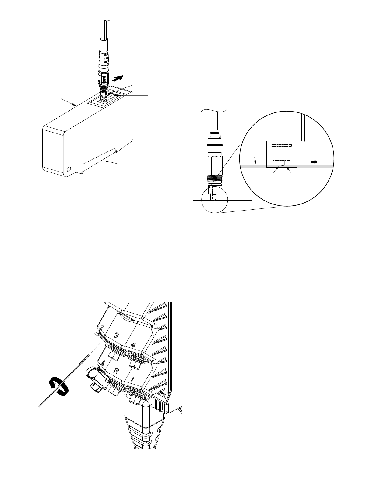
Page 28 of 29
© 2017 CommScope, Inc. All Rights Reserved
14.2.2. DLX adapter cleaning
14.2.2.1. Cleaning kit (FHD-ACC-CLNKIT1) is required
for this procedure.
14.2.2.2. Locate the dry swabs that are provided with the
connector/adapter cleaning kit.
14.2.2.3. Insert a dry swab into the adapter as shown
below. Note: Do not apply alcohol to the swab or the
adapter.
14.2.2.4. While applying light pressure against the connector end-face, rotate the dry swab 360º three times.
14.2.2.5. Dispose of the dry swab after use.
14.2.2.6. When connector end-face and adapter are
clean, install the drop cable connector into the optical
port.
ROTATE SWAB
THREE TIMES
14.3. Cleaning full size hardened
connector and adapter
14.3.1. Full size hardened connector cleaning
14.3.1.1. Clean both the optical port adapter and the
drop cable connector (requires accessory kit FHD-ACCCLNKIT1) as specied in ADCP-96-067.
14.3.1.2. Examine the end of the drop cable connector
and determine which is the high side which is the low side
of the connector end-face.
14.3.1.3. Locate the cleaning tape cassette that is provid-
ed with the cleaning kit.
14.3.1.4. Open the tape shutter by squeezing the lever
on the underside of the cassette and then keep the shutter open by continuing to squeeze the lever.
14.3.1.5. Hold the end-face of the drop cable connector
perpendicular to the cleaning tape and with the high side
of the connector pointing in the direction of cleaning.
14.3.1.6. With light pressure, slide the connector end-
face once across the tape in the direction shown using a
smooth linear motion. Do not press too hard and do not
repeat the cleaning motion with the same tape.
14.3.1.7. Release the lever on the underside of the cas-
sette to close the tape shutter.
14.3.1.8. Repeat Step 12.4.2.3 through 12.4.2.6 until the
connector has been cleaned three times.
14.3.1.9. When the connector and the adapter are clean,
install the connector into optical port..
HIGH SIDE
OF END-FACE
WIPE
DIRECTION
OF CLEANING
LOW SIDE
OF END-FACE
ANGLED CONNECTOR
DETAIL DRAWING
DIRECTION
OF CONNECTOR
MOTION
RAISED
PLATEN STRIP
BENEATH WIPE
CLEANING
CASSETTE
PROTRUSIONS
REPEAT CLEANING PROCEDURE
THREE TIMES USING A CLEAN TAPE
FOR EACH PASS. RELEASE AND
RE-SQUEEZE LEVER TO ADVANCE THE
TAPE
LEVER
Page 29

Page 29 of 29
© 2017 CommScope, Inc. All Rights Reserved
15. Trademarks
CommScope and all other trademarks identied by ® or
™ are registered trademarks or trademarks, respectively,
of CommScope, Inc.
16. Contact information
To nd out more about CommScope® products, visit us
on the web at www.commscope.com
For technical assistance, customer service, or to report
any missing/damaged parts, visit us at:
http://www.commscope.com/SupportCenter
This product is covered by one or more U.S. patents or
their foreign equivalents. For patents, see
www.commscope.com/ProductPatent/ProductPatent.aspx
14.3.2. Full size hardened adapter cleaning
14.3.2.1. Cleaning kit (FHD-ACC-CLNKIT1) is required
for this procedure.
14.3.2.2. Locate the dry swabs that are provided with the
connector/adapter cleaning kit.
14.3.2.3. Insert a dry swab into the adapter as shown
below. Note: Do not apply alcohol to the swab or the
adapter.
14.3.2.4. While applying light pressure against the connector end-face, rotate the dry swab 360º three times.
14.3.2.5. Dispose of the dry swab after use.
14.3.2.6. When connector end-face and adapter are
clean, install the drop cable connector into the optical
port.
DIRECTION
OF CLEANING
RAISED
PLATEN STRIP
BENEATH WIPE
CLEANING
CASSETTE
REPEAT CLEANING PROCEDURE
THREE TIMES USING A CLEAN TAPE
FOR EACH PASS. RELEASE AND
RE-SQUEEZE LEVER TO ADVANCE THE
TAPE
LEVER
ROTATE SWAB
THREE TIMES
 Loading...