

Page 1
22673-A
Fiber Distribution Hub
FDH 3000
288 Cabinet With Splicing
User Manual
ADCP-96-139
Rev B, July 2017
www.commscope.com
ADC-96-139 Rev B
Page 2

ADCP-96-139 • Rev B • July 2017 • Preface
COPYRIGHT
© 2017, CommScope Inc.
All Rights Reserved
REVISION HISTORY
ISSUE DATE REASON FOR CHANGE
1 3/2008 Original.
B July 2017 Updated to CommScope format.
TRADEMARK INFORMATION
CommScope, CommScope(logo), and NG4access are registered trademarks of CommScope, Inc.
ADC and ADC Telecommunications are registered trademarks of CommScope, Inc.
Telcordia is a registered trademark of Telcordia Technologies, Inc.
GORE is a registered trademark of W. L. Gore & Associates, Inc.
DISCLAIMER OF LIABILITY
Contents herein are current as of the date of publication. CommScope reserves the right to change the contents without prior notice.
In no event shall CommScope Inc. be liable for any damages resulting from loss of data, loss of use, or loss of profits and
CommScope Inc. further disclaims any and all liability for indirect, incidental, special, consequential or other similar
damages. This disclaimer of liability applies to all products, publications and services during and after the warranty period.
This publication may be verified at any ti me by con tacting CommSc ope’s Technical Assistance Center at 1.800.830.5056, or by email to TAC.Americas@commscope.com.
Page ii
Page 3

ABOUT THIS MANUAL
This publication describes the OmniReach FDH 3000 288 cabinet with splicing. Also included
are procedures for mounting the cabinet, installing and splicing feeder and distribution cables,
installing additional splitter modules, installing additional distribution panels, storing the
splitter output fibers, connecting the splitter output fibers to the distribution fibers, and
replacing damaged components.
RELATED PUBLICATIONS
Listed below are related manuals and their publication numbers. Copies of these publications
can be ordered on the CommScope website at the following URL:
http://www.commscope.com/SupportCenter
Title ADCP Number
Optical Fiber Connector Wet and Dry Cleaning Instructions 90-159
Plug And Play Splitter Installation Guide 96-087
ADCP-96-139 • Rev B • July 2017 • Preface
Round Splice Tray Cable Routing Instructions 90-321
Breakout and Moisture Blocking Kit for Dielectric Uni-Tube Cable Instructions 93-064
Breakout and Moisture Blocking Kit for Armored Uni-Tube Cable Instructions 93-039
ADMONISHMENTS
Important safety admonishments are used throughout this manual to warn of possible hazards to
persons or equipment. An admonishment identifies a possible hazard and then explains what
may happen if the hazard is not avoided. The admonishments — in the form of Dangers,
Warnings, and Cautions — must be followed at all times. These warnings are flagged by use of
the triangular alert icon (seen below) and are listed in descending order of severity of injury or
damage and likelihood of occurrence.
Danger: Danger is used to indicate the presence of a hazard that will cause severe personal
injury, death, or substantial property damage if the hazard is not avoided.
Warning: Warning is used to indicate the presence of a hazard that can cause severe personal
injury, death, or substantial property damage if the hazard is not avoided.
Caution: Caution is used to indicate the presence of a hazard that will or can cause minor
personal injury or property damage if the hazard is not avoided.
© 2017, ADC Telecommunications, Inc.
Page iii
Page 4

ADCP-96-139 • Issue A • June 2001 • Preface
GENERAL SAFETY PRECAUTIONS
Warning: Wet conditions increase the potential for receiving an electrical shock when
installing or using electrically-powered equipment. To prevent electrical shock, never install or
use electrical equipment in a wet location or during a lightning storm.
Danger: Do not look into the ends of any optical fiber. Exposure to laser radiation may result.
Do not assume the laser power is turned-off or that the fiber is disconnected at the other end.
Danger: Use adequate lifting equipment when moving or installing Fiber Distribution Hub
cabinets. Verify that the maximum lift weight rating of the equipment is sufficient to handle the
weight of the cabinet.
Danger: Do not stand under a Fiber Distribution Hub cabinet as it is being hoisted into
position for mounting. A failure of the lifting equipment or apparatus could result in serious
personal injury and cause significant damage to the cabinet.
Warning: Before digging, check with all local utilities for the presence of buried cables or
pipes. Contact with underground cables or pipes, especially electric power cables and gas
service lines, could interrupt local utility service and cause serious personal injury and
extensive property damage.
STANDARDS CERTIFICATION
Telcordia: This equipment complies with the applicable sections of GR-3125-CORE
LIST OF ACRONYMS AND ABBREVIATIONS
The acronyms and abbreviations used in this manual are detailed in the following list:
AWG American Wire Gauge
C Centigrade
F Fahrenheit
FDH Fiber Distribution Hub
FMS Mounting Sleeve
FTTP Fiber To The Premises
OSP Outside Plant
PMF Pad Mount Frame
PNP Plug and Play
Page iv
© 2017, ADC Telecommunications, Inc.
Page 5

TABLE OF CONTENTS
Content Page
About This Manual . . . . . . . . . . . . . . . . . . . . . . . . . . . . . . . . . . . . . . . . . . . . . . . . . . . . . . . . . . . . . . . . . . . . . . . . . . iii
Related Publications . . . . . . . . . . . . . . . . . . . . . . . . . . . . . . . . . . . . . . . . . . . . . . . . . . . . . . . . . . . . . . . . . . . . . . . . . iii
Admonishments . . . . . . . . . . . . . . . . . . . . . . . . . . . . . . . . . . . . . . . . . . . . . . . . . . . . . . . . . . . . . . . . . . . . . . . . . . . . iii
General Safety Precautions . . . . . . . . . . . . . . . . . . . . . . . . . . . . . . . . . . . . . . . . . . . . . . . . . . . . . . . . . . . . . . . . . . . . .iv
Standards Certification . . . . . . . . . . . . . . . . . . . . . . . . . . . . . . . . . . . . . . . . . . . . . . . . . . . . . . . . . . . . . . . . . . . . . . . .iv
List of Acronyms and Abbreviations . . . . . . . . . . . . . . . . . . . . . . . . . . . . . . . . . . . . . . . . . . . . . . . . . . . . . . . . . . . . . . . .iv
1 DESCRIPTION. . . . . . . . . . . . . . . . . . . . . . . . . . . . . . . . . . . . . . . . . . . . . . . . . . . . . . . . . . . . . . . . . . . . . . . . . . 1
1.1 General Description. . . . . . . . . . . . . . . . . . . . . . . . . . . . . . . . . . . . . . . . . . . . . . . . . . . . . . . . . . . . . . . . 1
1.2 Main Components . . . . . . . . . . . . . . . . . . . . . . . . . . . . . . . . . . . . . . . . . . . . . . . . . . . . . . . . . . . . . . . . . 2
1.3 Specifications and Dimensions . . . . . . . . . . . . . . . . . . . . . . . . . . . . . . . . . . . . . . . . . . . . . . . . . . . . . . . . 3
2 BEFORE STARTING THE INSTALLATION . . . . . . . . . . . . . . . . . . . . . . . . . . . . . . . . . . . . . . . . . . . . . . . . . . . . . . . . 5
2.1 Installation Overview . . . . . . . . . . . . . . . . . . . . . . . . . . . . . . . . . . . . . . . . . . . . . . . . . . . . . . . . . . . . . . . 5
2.2 Unpacking and Inspection. . . . . . . . . . . . . . . . . . . . . . . . . . . . . . . . . . . . . . . . . . . . . . . . . . . . . . . . . . . . 5
2.3 Cabinet Installation Hardware. . . . . . . . . . . . . . . . . . . . . . . . . . . . . . . . . . . . . . . . . . . . . . . . . . . . . . . . . 6
2.4 OSP Cable and Cabinet Grounding Cables. . . . . . . . . . . . . . . . . . . . . . . . . . . . . . . . . . . . . . . . . . . . . . . . . 6
2.5 Tools and Materials Required for Installation . . . . . . . . . . . . . . . . . . . . . . . . . . . . . . . . . . . . . . . . . . . . . . 6
2.6 Cabinet Mounting . . . . . . . . . . . . . . . . . . . . . . . . . . . . . . . . . . . . . . . . . . . . . . . . . . . . . . . . . . . . . . . . . 7
3 MOUNTING THE CABINET ON A MOUNTING SLEEVE . . . . . . . . . . . . . . . . . . . . . . . . . . . . . . . . . . . . . . . . . . . . . . . . 7
3.1 Installation Recommendations . . . . . . . . . . . . . . . . . . . . . . . . . . . . . . . . . . . . . . . . . . . . . . . . . . . . . . . . 8
3.2 Excavation . . . . . . . . . . . . . . . . . . . . . . . . . . . . . . . . . . . . . . . . . . . . . . . . . . . . . . . . . . . . . . . . . . . . . . 8
3.3 Placement of the FMS . . . . . . . . . . . . . . . . . . . . . . . . . . . . . . . . . . . . . . . . . . . . . . . . . . . . . . . . . . . . . . 9
3.4 Cable Conduit Installation. . . . . . . . . . . . . . . . . . . . . . . . . . . . . . . . . . . . . . . . . . . . . . . . . . . . . . . . . . . 10
3.5 Grounding System Installation. . . . . . . . . . . . . . . . . . . . . . . . . . . . . . . . . . . . . . . . . . . . . . . . . . . . . . . . 10
3.6 Back Fill. . . . . . . . . . . . . . . . . . . . . . . . . . . . . . . . . . . . . . . . . . . . . . . . . . . . . . . . . . . . . . . . . . . . . . . 10
3.7 Mounting the Cabinet on the FMS . . . . . . . . . . . . . . . . . . . . . . . . . . . . . . . . . . . . . . . . . . . . . . . . . . . . . 10
3.8 Grounding Wire Connection To Cabinet. . . . . . . . . . . . . . . . . . . . . . . . . . . . . . . . . . . . . . . . . . . . . . . . . . 13
4 MOUNTING THE CABINET ON A CONCRETE PAD . . . . . . . . . . . . . . . . . . . . . . . . . . . . . . . . . . . . . . . . . . . . . . . . . 14
4.1 Installation Recommendations . . . . . . . . . . . . . . . . . . . . . . . . . . . . . . . . . . . . . . . . . . . . . . . . . . . . . . . 14
4.2 Base Construction and Conduit Installation . . . . . . . . . . . . . . . . . . . . . . . . . . . . . . . . . . . . . . . . . . . . . . . 14
4.3 Concrete Pad Construction . . . . . . . . . . . . . . . . . . . . . . . . . . . . . . . . . . . . . . . . . . . . . . . . . . . . . . . . . . 16
4.4 Grounding System Installation. . . . . . . . . . . . . . . . . . . . . . . . . . . . . . . . . . . . . . . . . . . . . . . . . . . . . . . . 17
4.5 Mounting the Cabinet on the Concrete Pad . . . . . . . . . . . . . . . . . . . . . . . . . . . . . . . . . . . . . . . . . . . . . . . 17
4.6 Grounding Wire Connection To Cabinet. . . . . . . . . . . . . . . . . . . . . . . . . . . . . . . . . . . . . . . . . . . . . . . . . . 20
5 FEEDER CABLE INSTALLATION AND SPLICING . . . . . . . . . . . . . . . . . . . . . . . . . . . . . . . . . . . . . . . . . . . . . . . . . . 20
5.1 Cable Bracket Cover Removal/Installation. . . . . . . . . . . . . . . . . . . . . . . . . . . . . . . . . . . . . . . . . . . . . . . . 21
5.2 Feeder Cable Installation . . . . . . . . . . . . . . . . . . . . . . . . . . . . . . . . . . . . . . . . . . . . . . . . . . . . . . . . . . . 21
5.3 Grounding the Feeder Cable . . . . . . . . . . . . . . . . . . . . . . . . . . . . . . . . . . . . . . . . . . . . . . . . . . . . . . . . . 24
5.4 Splicing the Feeder Cable Fibers . . . . . . . . . . . . . . . . . . . . . . . . . . . . . . . . . . . . . . . . . . . . . . . . . . . . . . 26
6 DISTRIBUTION CABLE INSTALLATION AND SPLICING. . . . . . . . . . . . . . . . . . . . . . . . . . . . . . . . . . . . . . . . . . . . . . 30
6.1 Distribution Cable Installation. . . . . . . . . . . . . . . . . . . . . . . . . . . . . . . . . . . . . . . . . . . . . . . . . . . . . . . . 30
6.2 Grounding the Distribution Cables . . . . . . . . . . . . . . . . . . . . . . . . . . . . . . . . . . . . . . . . . . . . . . . . . . . . . 32
ADCP-96-139 • Rev B • July 2017 • Preface
© 2017, ADC Telecommunications, Inc.
Page v
Page 6

ADCP-96-139 • Rev B • July 2017 • Preface
TABLE OF CONTENTS
Content Page
6.3 Splicing the Distribution Cable Fibers . . . . . . . . . . . . . . . . . . . . . . . . . . . . . . . . . . . . . . . . . . . . . . . . . . 35
7 PLUG AND PLAYER SPLITTER MODULE INSTALLATION . . . . . . . . . . . . . . . . . . . . . . . . . . . . . . . . . . . . . . . . . . . . 41
8 ROUTING AND CONNECTING THE SPLITTER OUTPUT FIBERS . . . . . . . . . . . . . . . . . . . . . . . . . . . . . . . . . . . . . . . . 43
8.1 Storing The Splitter Output Fibers . . . . . . . . . . . . . . . . . . . . . . . . . . . . . . . . . . . . . . . . . . . . . . . . . . . . . 43
8.2 Enabling Service To a Subscriber . . . . . . . . . . . . . . . . . . . . . . . . . . . . . . . . . . . . . . . . . . . . . . . . . . . . . 44
9 PASS-THROUGH ROUTING PROCEDURES . . . . . . . . . . . . . . . . . . . . . . . . . . . . . . . . . . . . . . . . . . . . . . . . . . . . . 45
9.1 Sliding Adapter Pack Pass-Through Routing Procedure . . . . . . . . . . . . . . . . . . . . . . . . . . . . . . . . . . . . . . 45
9.2 Splitter Compartment Pass-Through Routing Procedure . . . . . . . . . . . . . . . . . . . . . . . . . . . . . . . . . . . . . . 46
10 MAINTENANCE AND REPAIR PROCEDURES . . . . . . . . . . . . . . . . . . . . . . . . . . . . . . . . . . . . . . . . . . . . . . . . . . . . 48
10.1 Painting. . . . . . . . . . . . . . . . . . . . . . . . . . . . . . . . . . . . . . . . . . . . . . . . . . . . . . . . . . . . . . . . . . . . . . . 48
10.2 Distribution Panel Adapter Replacement . . . . . . . . . . . . . . . . . . . . . . . . . . . . . . . . . . . . . . . . . . . . . . . . 48
10.3 Splitter Compartment Adapter Replacement. . . . . . . . . . . . . . . . . . . . . . . . . . . . . . . . . . . . . . . . . . . . . . 50
10.4 Replacing a Damaged Fiber or Connector. . . . . . . . . . . . . . . . . . . . . . . . . . . . . . . . . . . . . . . . . . . . . . . . 51
10.4.1 Splitter Output Fiber Connector Replacement . . . . . . . . . . . . . . . . . . . . . . . . . . . . . . . . . . . . . . 52
10.5 Door Gasket Replacement . . . . . . . . . . . . . . . . . . . . . . . . . . . . . . . . . . . . . . . . . . . . . . . . . . . . . . . . . . 52
10.6 Door Replacement . . . . . . . . . . . . . . . . . . . . . . . . . . . . . . . . . . . . . . . . . . . . . . . . . . . . . . . . . . . . . . . 52
10.7 Grounding System Terminal Access Procedure . . . . . . . . . . . . . . . . . . . . . . . . . . . . . . . . . . . . . . . . . . . . 54
11 CUSTOMER INFORMATION AND ASSISTANCE. . . . . . . . . . . . . . . . . . . . . . . . . . . . . . . . . . . . . . . . . . . . . . . . . . . 56
Page vi
© 2017, ADC Telecommunications, Inc.
Page 7
1 DESCRIPTION
22673-A
1.1 General Description
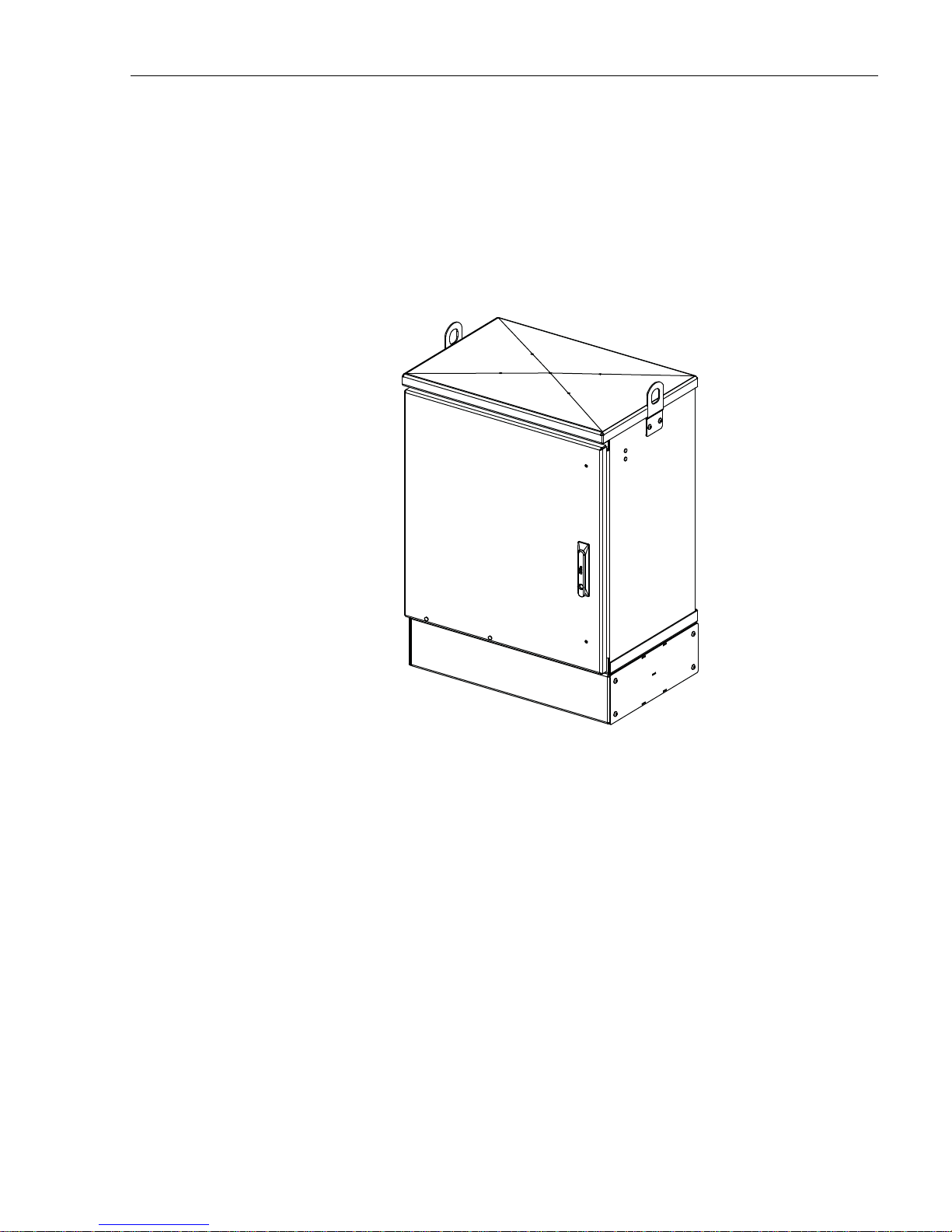
The 288 cabinet with splicing is a secure, above-ground, outdoor fiber optic distribution cabinet
that is designed to hold the various optical components required for Fiber To The Premises
(FTTP) distribution network applications. The cabinet is designed for pedestal-mount
applications. Figure 1 shows a typical cabinet.
ADCP-96-139 • Rev B • July 2017
Figure 1. Typical Cabinet
The cabinet may be mounted on a concrete pad or on a mounting sleeve. Mounting kits
(accessories) are available for each mounting option. The feeder and distribution cables
(stranded cable only) enter/exit the cabinet from the bottom.
Clamps are provided for securing the cables to the inside of the cabinet. The bottom of the
cabinet is enclosed with a moisture barrier. The cable entry/exit hole is fitted with a flexible
membrane to resist the entry of dust, moisture, and insects. GORE membrane vents are
provided to release any moisture that may accumulate within the cabinet.
The exterior shell of the cabinet is constructed of heavy gauge aluminum and is coated with an
almond-colored finish. Each cabinet is equipped with a single front door equipped with a
tamper-resistant latch, padlock hasp, stainless steel hinges, and door catches that prevent
accidental closing. Access to the cabinet requires a
216B key tool (accessory) to release the latch
handle. Lifting eyes are provided for hoisting the cabinet into position for mounting. Each
cabinet is equipped with a 6-inch ground spacer/riser for extra ground clearance. An additional
spacer/riser (accessory item) can be installed if even more ground clearance is required.
© 2017, ADC Telecommunications, Inc.
Page 1
Page 8
ADCP-96-139 • Rev B • July 2017
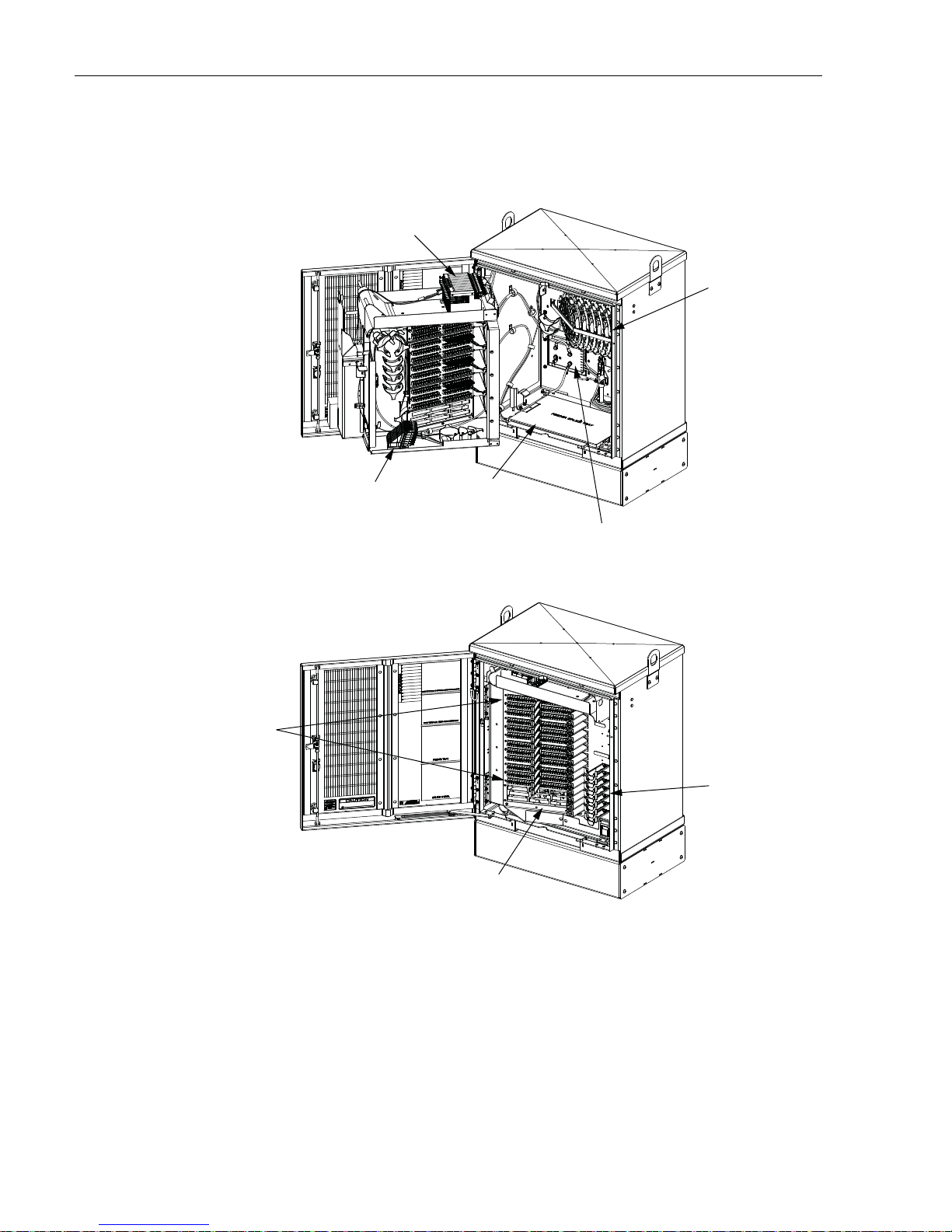
1.2 Main Components
Figure 2 shows the main components of a typical 288 cabinet with splicing. Included are:
SPLITTER
COMPARTMENT
DISTRIBUTION
SPLICE WHEEL
STORAGE
DISTRIBUTION
PANELS
SLIDING
ADAPTER
PAC K
FEEDER
SPLICE TRAY
STORAGE
STORAGE
PA NE L
GROUNDING
BLOCK
RADIUS
LIMIITERS
22674-A
Figure 2. Main Components of a Typical 288 Cabinet With Splici ng
• Distribution Panels: Provide a point for connecting the splitter output fibers with the
terminated distribution cable fibers. Each panel provides mounting spaces for 72 bulkhead
adapters. The cabinet may be ordered with one to six distribution panels installed.
Additional panels may be ordered and installed as needed. UPC/SC or APC/SC style
connectors are available.
Page 2
© 2017, ADC Telecommunications, Inc.
Page 9

ADCP-96-139 • Rev B • July 2017
• Storage Panel: Provides a temporary “parking lot” for unused splitter output fibers. Each
splitter module comes with a connector pack that mounts in the storage panel. Up to nine
8-position connector packs (72 fibers total) can be mounted in the storage panel.
• Radius Limiters: Provide a place for storing excess slack from the splitter output fibers.
• Splitter Compartment: Provides a place for mounting the splitters. Will support up to 12
splitters. Unused splitter slots can be used for pass-though fibers. The splitters specified
for use with the FDH 3000 cabinet are equipped with bend-optimized fibers.
• Sliding Adapter Pack (Input panel): Provides a place for terminating spare feeder cable
fibers. Will support up to 36 adapters. Spare feeder cable fibers are typically used for
signal pass-through functions.
• Grounding Block: Provides a point for grounding the cabinet and OSP cables.
• Feeder Cable Splice Tray Storage: Provides storage for one or two 5 x 11.75 inch
rectangular splice trays which are used for splicing the feeder cable fibers to the splitter
input pigtails. Each stranded cable splice tray provides storage for up to 36 splices.
• Distribution Cable Splice Tray Storage: Provides storage for up to thirty-six round
splice trays which are used for splicing the distribution cable fibers to the distribution
panel pigtails. Each stranded cable splice tray provides storage for up to twelve splices.
1.3 Specifications and Dimensions
Table 1 lists the specifications for the FDH 3000 288 cabinet. Figure 3 shows dimensions.
Table 1. 288 Cabinet With Splicing Specifications
PARAMETER SPECIFICATION
Cabinet
Dimensions (H x W x D)
Pedestal-Mount (See Figure 3) 36.0 x 26.8 x 18.2 inches (91.3 x 68.1 x 46.2 cm)
Weight (fully loaded) 208 lbs (94.3kg)
Certification (pending) GR-3125-CORE
Distribution panels (maximum) 4
Distribution ports Up to 288 with four 72-port distribution panels.
Distribution port adapters/connectors UPC/SC or APC/SC,
Splitter compartment splitter capacity 12 splitters
Splitter compartment adapter capacity 24 adapters
Storage panel capacity 72 connectors
Sliding adapter pack capacity 36 adapters
Splitter Modules
Splitter module input and output pigtails Bend-optimized fiber terminated with UPC/SC or APC/
Test bandpass 1260–1360 nm, 1480–1500 nm, 1550–1560 nm
SC connectors
© 2017, ADC Telecommunications, Inc.
Page 3
Page 10

ADCP-96-139 • Rev B • July 2017
PARAMETER SPECIFICATION
Overall bandpass 1260–1625 nm
Return loss at test bandpass >
Maximum insertion loss at test bandpass
1 x 2
1 x 4
1 x 8
1 x 16
1 x 32
1 x 64
2 x 16
2 x 32
Table 1. 288 Cabinet With Splicing Specifications, continued
55 dB
Note: Includes loss from input and output connectors
4.1 dB with UPC, 4.3 with APC
7.6 dB with UPC, 7.8 dB with APC
10.7 dB with UPC, 10.9 dB with APC
13.9 dB with UPC, 14.1 dB with APC
17.1 dB with UPC, 17.3 dB with APC
20.8 dB with UPS, 21 dB with APC
14.5 dB with UPC, 14.7 dB with APC
17.8 dB with UPC, 18 with APC
35.96 INCHES
(91.3 CM)
26.8 INCHES
(68.1 CM)
18.2 INCHES
(46.2 CM)
22675-A
Page 4
© 2017, ADC Telecommunications, Inc.
Figure 3. Typical 288 Cabinet With Splicing
Page 11

2 BEFORE STARTING THE INSTALLATION
2.1 Installation Overview
Installation of the 288 cabinet with splicing involves the following main tasks:
Mounting the Cabinet – The cabinet must be mounted on a support base. The following two
mounting options are available:
• Mounting Sleeve (FMS) – The FMS is a polymer concrete sleeve that mounts in the
ground. The FMS provides a stable mounting platform plus storage space under the
cabinet for OSP cable slack. The FMS may also be used as a splicing vault for OSP cables.
• Poured Concrete Pad – Concrete base with Pad Mounting Frame (PMF). The PMF is a
stainless-steel frame that is embedded in the concrete during installation of the pad. The
cabinet attaches to the PMF which holds it securely to the pad.
Splitter Installation – The cabinet may be ordered with one or two splitters. If additional
splitters are required, they must be ordered separately. All splitter modules that are ordered
separately must be installed in the splitter compartment.
ADCP-96-139 • Rev B • July 2017
Feeder Cable Installation – The feeder cable must be routed to the cabinet and spliced to the
splitter input fibers.
Distribution Cable Installation - The distribution cables must be routed to the cabinet and
spliced to the distribution panel pigtails.
Splitter Output Fiber Connections – Service is enabled by connecting the splitter output fiber
connectors to the subscriber distribution ports. Unused output fibers are temporarily “parked” in
the storage panel until they are needed for service.
2.2 Unpacking and Inspection
Use the following procedure to unpack and inspect the cabinet and all accessories:
1. Inspect the exterior of the shipping container(s) for evidence of rough handling that may
have damaged the components in the container.
2. Unpack each container while carefully checking the contents for damage a nd verify with
the packing slip.
3. If damage is found or parts are missing, file a cla im with th e comm ercial c arrier an d notify
ADC Customer Service. Save the damaged cartons for inspection by the carrier.
4. Refer to Section 11 of this manual if you need to contact ADC.
5. Save all shipping containers for use if the equipment requires shipment at a future date.
© 2017, ADC Telecommunications, Inc.
Page 5
Page 12

ADCP-96-139 • Rev B • July 2017
2.3 Cabinet Installation Hardware
The cabinet is shipped with various parts (see Table 2) for securing the cabinet to the FMS or
PMF. Verify that the specified cabinet installation hardware is received.
Table 2. Cabinet Installation Hardware
ITEM QUANTITY
3/8 x 1-inch hex head capscrews 4
3/8-inch flat washers 4
3/8-inch lock washers 4
Isolation gasket 1
2.4 OSP Cable and Cabinet Grounding Cables
The cabinet is equipped with a common grounding block that is used to tie together all the
components of the cabinet that must be grounded. The cabinet itself and any OSP cables with
metallic strength members must be connected to an earth ground source. Information on
grounding is provided in the sections that cover cabinet mounting.
2.5 Tools and Materials Required for Installation
The following tools and materials are required for all cabinet installation:
All Cabinet Installations
•Hammer
• Wire cutter
• Utility knife
• Screwdriver (flat blade)
• Torque wrench (with 7/16-inch socket and standard screwdriver socket)
• Tape measure
• Pen or marker
• 9/16-inch wrench
• 216B key tool (accessory - required to open cabinet door)
• 3/16-inch hex-key (required to open riser panels or remove lifting eyes)
• Level
• Padlock (optional)
• Grounding system, copper wire, and grounding clamp (per local requirements)
• Splicing equipment for splicing OSP feeder and distribution cables
Page 6
© 2017, ADC Telecommunications, Inc.
Page 13

ADCP-96-139 • Rev B • July 2017
• Tamping equipment
• Excavation and earth moving equipment
• Lifting equipment for hoisting the cabinet into position for mounting
• Landscaping equipment and site restoration supplies
Mounting Sleeve Installation
The following additional materials are required for mounting the cabinet on a mounting sleeve:
• Mounting Sleeve kit (FMS-ACE100-KIT-A)
• Stone aggregate
• Hole saw and drill (use to cut holes for cable conduit if pre-drilled holes are not usable)
Concrete Pad Installation
The following additional materials are required for mounting the cabinet on a concrete pad:
• Pad Mount Frame kit for FDH 3000 cabinet (FD3-PMFE06)
• Concrete finishing equipment
• Approximately 11.5 cu. ft. concrete
• Sand or gravel
• 2 x 6 inch framing lumber
• 1 x 4 inch wooden stakes (4)
• Nails and construction screws
• Utility wire (to secure PMF during installation)
•Saw
• Drill with screwdriver bits
•Square
2.6 Cabinet Mounting
The next two sections provide installation instructions for the various cabinet mounting systems.
Use whichever procedure is appropriate for the installation.
3 MOUNTING THE CABINET ON A MOUNTING SLEEVE
The FMS, shown in Figure 4, is a polymer concrete sleeve that may be used to support the
cabinet at ground level. The FMS may also be used as a splicing vault. Four vertical racks are
molded into the sides of the FMS to accommodate removable rungs (not provided ). The rungs
provide support for splice cases or OSP cable storage.
© 2017, ADC Telecommunications, Inc.
Page 7
Page 14

ADCP-96-139 • Rev B • July 2017
3.1 Installation Recommendations
The site chosen for the installation must conform to all local codes and any permits required
must be obtained prior to the start of installation. The location must be accessible and provide
adequate parking for worker and vehicle safety. Situate the FMS close to the trench that was
used for routing the OSP fiber cables for the network distribution system.
The installed cabinet must not create a visual or physical obstruction to vehicular or pedestrian
traffic. Ensure that there is sufficient space on all sides to facilitate cabinet installation.
Depending on the landscaping requirements, the top surface of the mounting sleeve may be
located from 0 to 4 inches (10.2 cm) above the surrounding grade.
30.13 IN.
FMS COVER
FMS ADAPTER
COVER
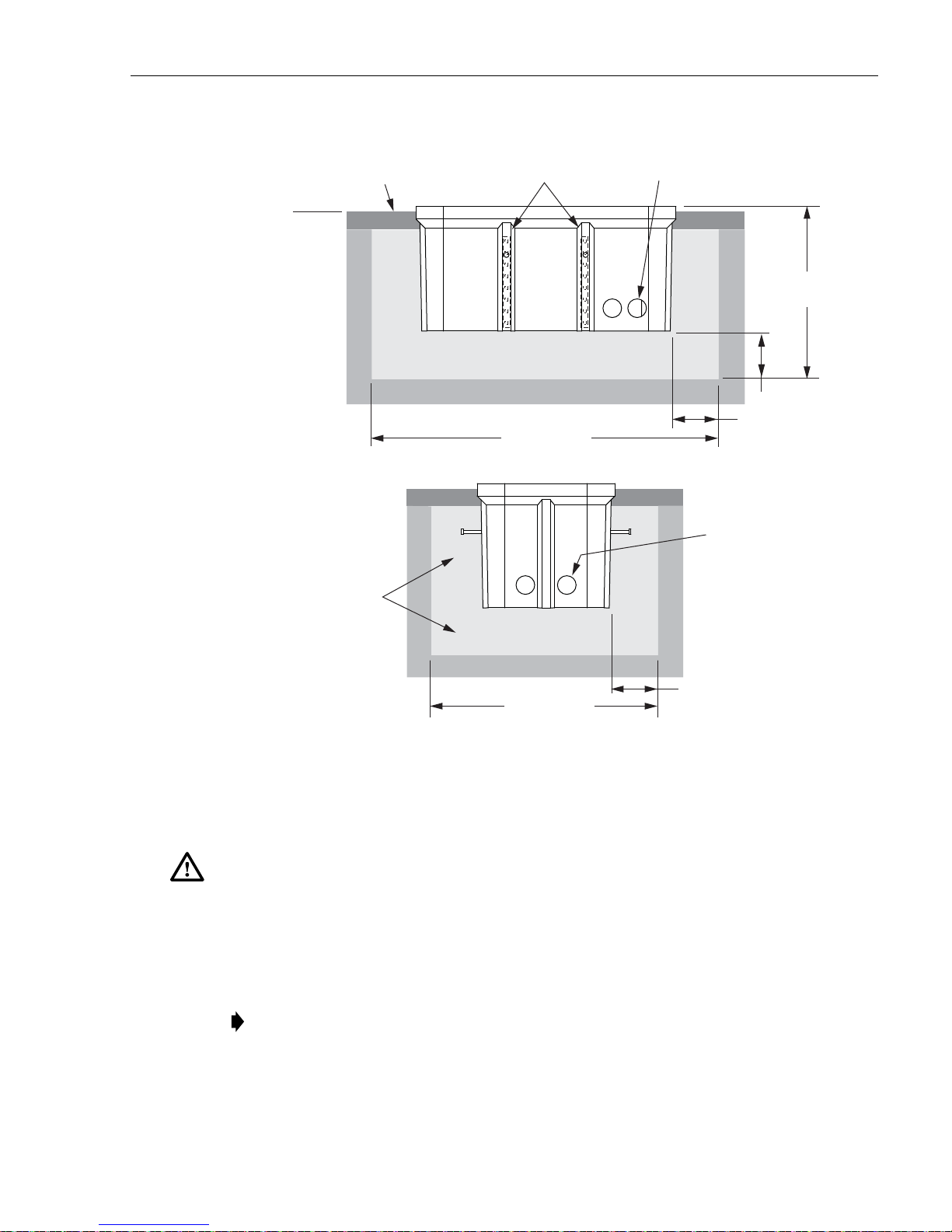
3.2 Excavation
The excavation must be large enough to provide a fill base that will maintain stability for the
FMS and the cabinet mounted on it. There must be room for 12 inches (30.5 cm) of fill belo w
and on each side of the FMS. The excavation dimensions for the FMS are shown in Figure 5.
Excavate a rectangular hole for the FMS.
29.69 IN.
MOUNTING
SLEEVE (FMS)
30.0 IN.
59.5 IN.
30.0 IN.
21510-D
Figure 4. Mounting Sleeve (FMS-ACE100-KIT-A)
Page 8
© 2017, ADC Telecommunications, Inc.
Page 15
ADCP-96-139 • Rev B • July 2017
21511-A
84 IN (213 CM)
54 IN (137 CM)
TOPSOIL OR
DECORATIVE ROCK
STONE
AGGREGATE FILL
STONE
AGGREGATE FILL
42 IN
(106.7 CM)
12 IN
(30.5 CM)
12 IN
(30.5 CM)
CONDUIT
ENTRANCE
HOLES
COMPACTED SOIL
COMPACTED SOIL
TAMP AGGREGATE AS
HOLE IS FILLED
GRADE
SIDE
VIEW
END
VIEW
CONDUIT
ENTRANCE
HOLES
VERTICAL RACKS
FOR MANHOLE
CABLE SUPPORT BARS
3.3 Placement of the FMS
Danger: Use adequate lifting equipment when installing the FMS. Do not stand in the hole while
placing the FMS in position. An unexpected shift of the FMS could result in personal injury.
Use the following procedures to place the FMS into the excavation.
1. Fill the bottom of the ho le with stone aggregate, tamping it as it is filled to build a 12 inch
(30.5 cm) layer with a level surface. The stone aggregate will provide a stable base to
support the FMS.
Note: Use crushed rock 3/8-inch or less in size mixed with stone dust (per local practice)
to fill the hole. The name of the material may differ in different geographical areas.
Possible names are Class 5, stone dust, aughts (0s) and ones (1s), or stone aggregate
Figure 5. Excavation Recommendations for FMS-ACE100-KIT-A
© 2017, ADC Telecommunications, Inc.
Page 9
Page 16

ADCP-96-139 • Rev B • July 2017
2. Use appropriate lifting equipment to place the FMS into the center of the hole. Lifting
loops are provided on either side of the FMS for attaching a sling or chain.
3. Use a carpenter’s level to verify that the FMS is level. If it is necessary to add or remove
fill for leveling, tamp any added fill to maintain the base stability.
3.4 Cable Conduit Installation
Select the conduit entrance holes (see Figure 5) for the OSP feeder and distribution cables. If
necessary, additional conduit entrance holes may be cut using a power drill and hole saw. Place
and route the conduit into the entrance hole(s). If preferred, the FMS may be installed without
conduit. OSP cables may be routed into the FMS at any point that is convenient. Cut the cable
entrance hole to match the size of the cable.
3.5 Grounding System Installation
Install a grounding system (not provided) that meets all local electrical codes. Check local codes
for grounding system installation, use of clamps, wire size, and any other grounding
requirements. Typically, #6 AWG copper wire is used for the grounding wire. Install the
grounding system inside the FMS where it will not interfere with the conduit or cables. Leave
sufficient slack in the grounding wire to allow it to be routed into the cabinet after the cabinet is
mounted on the sleeve.
3.6 Back Fill
If installing conduit, hand shovel stone aggregate under the conduit to avoid damage from the
power tamper. Complete the back fill as follows:
1. Add stone aggregate evenly around the FMS and tamp. Fill to approximately 6 inches
(15.2 cm) from the top of the excavation.
2. Complete the back-fill with crushed rock or topsoil depending on the landscaping
requirements. The top surface of the mounting sleeve may be located from 0 to 4 inches
(10.2 cm) above the surrounding grade (see Figure 5).
3.7 Mounting the Cabinet on the FMS
Use the 216B key tool to un-latch and latch the cabinet door as needed during th e mounting
process. Refer to Figure 6 as necessary when mounting the cabinet.
Warning: Use appropriate lifting equipment when moving or installing the cabinet. Do not
stand under a cabinet as it is being hoisted into position for mounting. A failure of the lifting
equipment could result in serious personal injury.
Page 10
© 2017, ADC Telecommunications, Inc.
Page 17
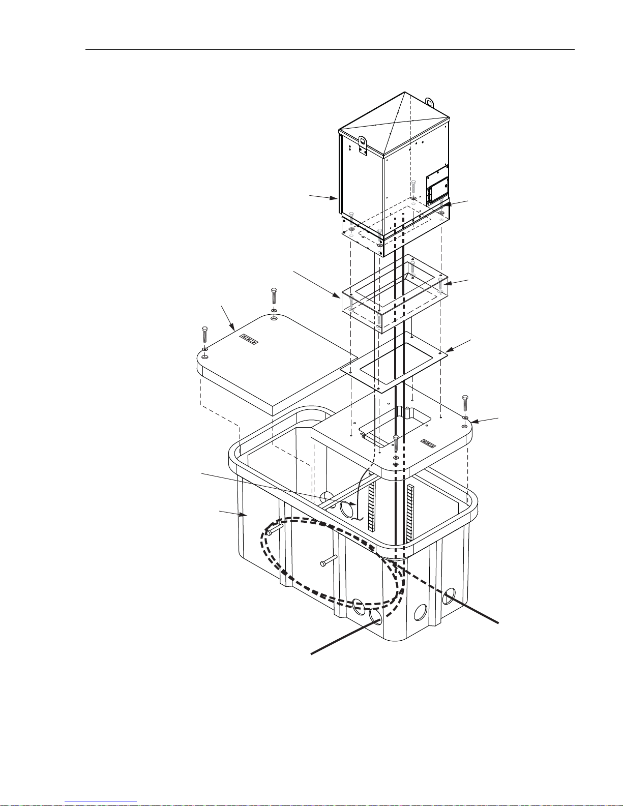
288 TERMINATION
FDH 3000 CABINET
(FRONT)
ADCP-96-139 • Rev B • July 2017
CAPSCREWS (4), LOCK
WASHERS (4), AND FLAT
WASHERS (4)
FMS COVER
GROUNDING
WIRE
GROUND SPACER
(OPTIONAL ACCESSORY)
FMS
CAPSCREWS (4), LOCK
WASHERS (4), AND FLAT
WASHERS (4)
CABINET FRONT
ISOLATION GASKET
FMS ADAPTER
COVER
Figure 6. Mounting the 288 Termination Cabinet With Splicing on the FMS
Use the following procedure to mount the cabinet on the FMS:
22677-A
Page 11
© 2017, ADC Telecommunications, Inc.
Page 18
ADCP-96-139 • Rev B • July 2017
22678-A
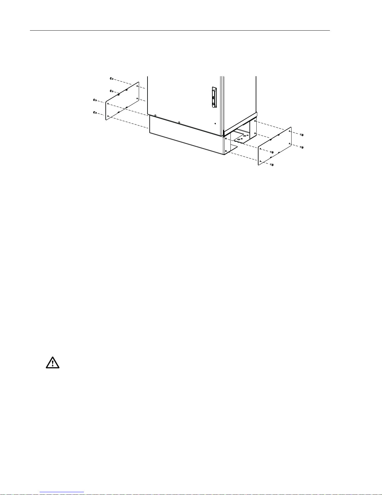
1. Use a 3/16-inch hex-key to remove the screws that secure the access covers to the left and
right sides of the cabinet ground spacer/riser as shown in Figure 7.
2. Remove the access covers from the ground spacer/riser and set aside both the covers and
the screws for reuse.
Figure 7. Removing Side Access Covers From Ground Spacer/Riser
3. Mount the FMS adapter cover on the FMS and secure using the two capscrews and flat
washers provided. Tighten each capscrew securely.
4. Place the isolation gasket (provided with cabinet) on the adapter cover and align the holes
in the gasket with the holes in the adapter cover. Make sure the wide side of the gasket is
on the side of the adapter cover that corresponds to the front side of the cabinet.
5. If a ground spacer/riser (optional accessory) will be installed, place the spacer in position
for mounting on the adapter cover. The isolation gasket installed in step 4 should remain in
place between the adapter cover and ground spacer. If a ground spacer will not be
installed, proceed to step 8.
6. Align the mounting holes in the spacer/riser with the mounting holes in the adapter cover.
7. Secure the spacer/riser to the adapter cover using the four capscrews, four lock washers,
and four flat washers provided with the spacer. Tighten all capscrews securely.
8. Using appropriate lifting equipment, hoist the cabinet into position for mounting on the
spacer/riser or adapter cover.
Danger: Do not stand directly under the cabinet as it is being hoisted into position for cable
installation. A failure of the lifting equipment could result in serious personal injury.
9. Lower the cabinet onto the ground spacer/riser or adapter cover and align the mounting
holes in the cabinet base with the threaded holes in the spacer/riser or adapter cover. If a
spacer/riser was not installed, leave the isolation gasket (installed in step 4) in place on the
adapter cover.
10. Secure the cabinet to the spacer/riser or adapter cover using the four capscrews, lock
washers, and flat washers provided with the cabinet Tighten all four capscrews securely.
11. Install the FMS sleeve cover on the FMS and secure using the two capscrews and washers
provided. Tighten both capscrews securely.
Page 12
© 2017, ADC Telecommunications, Inc.
Page 19
Note: The FMS sleeve cover may be installed at a later time so the interior of the FMS
22681-A
TIGHTEN GROUNDING LUG SET SCREW
TO 30 TO 35 LBS FORCE - INCHES
(3.4 TO 4.0 Nm) OF TORQUE
GROUNDING WIRE
ENTRY POINT
GROUNDING
LUG
GROUNDING
CABLE
sleeve to be accessed for cable installation, ground wire installation, or splicing.
12. The lifting eyes may be left in place or removed from the cabinet. To remove the lifting
eyes, use the 3/16 hex-key to remove the lifting eye screws. Store the lifting eyes inside the
cabinet and then re-install the lifting eye screws in the cabinet.
3.8 Grounding Wire Connection To Cabinet
Prior to mounting the cabinet, a grounding system and grounding wire should have been
installed (see Section 3.5) in the space below the cabinet. Use the following procedure to
connect the grounding wire to the cabinet:
1. Locate the grounding wire that was installed inside the FMS prior to mounting the cabinet.
2. Working from the bottom side of the cabinet, insert the grounding wire through the
flexible membrane at the point indicated in Figure 8.
ADCP-96-139 • Rev B • July 2017
3. Attach the grounding wire to the cabinet grounding lug. The grounding lug can be used for
#6 to #14 AWG wire.
4. Tighten the grounding lug set screw to 30 to 35 lbs force-inches (3.4 to 4.0 Nm) of torque.
5. Reinstall the left and right access covers that were removed in step 1 of Section 3.7. Use
the 3/16-inch hex-key to tighten the screws that secure the access covers to the sides of the
cabinet ground spacer/riser.
Figure 8. Grounding Wire Connection To Cabinet
Page 13
© 2017, ADC Telecommunications, Inc.
Page 20

ADCP-96-139 • Rev B • July 2017
21400-B
28.35 IN.
(72.0 CM)
18.35 IN.
(46.6 CM)
5.5 IN.
(14.0 CM)
4 MOUNTING THE CABINET ON A CONCRETE PAD
The Pad Mount Frame (PMF), shown in Figure 9, is a stainless steel frame that provides a
mounting base for the cabinet when embedded in a concrete foundation.
Caution: Mounting the cabinet directly on a concrete pad may cause chemical corrosive action
to the cabinet. Use only the Pad Mount Frame (PMF) as a mounting base for the cabinet. Do
not use caulking compounds as a sealer between the cabinet and the PMF.
Figure 9. Pad Mount Frame Dimensions
4.1 Installation Recommendations
The site chosen for the installation must conform to all local codes and any permits required
must be obtained prior to the start of installation. The location must be accessible and provide
adequate parking for worker and vehicle safety. Situate the concrete pad close to the trench that
was used for routing the OSP fiber cables for the network distribution system.
The installed cabinet must not create a visual or physical obstruction to vehicular or pedestrian
traffic. Ensure that there is sufficient space on all sides to facilitate cabinet installation.
Depending on the landscaping requirements, the top surface of the concrete pad may be located
from 0 to 3 inches (7.6 cm) above the surrounding grade.
4.2 Base Construction and Conduit Installation
Prepare a base for the concrete pad that meets all local code requirements. The base must have a
footing of 4 to 6 inches (10.2 to 15.2 cm) of sand or gravel (per local practice) on firmly
compacted soil. Refer to the construction diagram in Figure 10 for details.
Install the cable conduit from below and position it so that the top of each upward bend will be
located within the PMF opening at the indicated point. When installed, the top of the conduit
should be located 1 to 2 inches (2.54 to 5.08 cm) below the top of the finished concrete pad.
Install the conduit before pouring the pad.
Page 14
© 2017, ADC Telecommunications, Inc.
Page 21

44.5 IN.
(113.0 CM)
4 IN. DUCT FOR
FEEDER CABLE
(LOCATE 1 - 2 INCHES
BELOW TOP OF PAD)
ADCP-96-139 • Rev B • July 2017
20.25 IN.
(51.4 CM)
15.25 IN
(38.7 CM)
8.0 IN.
(20.3 CM)
GROUND ROD
(LOCATE 1 - 2 INCHES
BELOW TOP OF PAD)
PAD MOUNT FRAME
CAST IN PLACE
REINFORCED
CONCRETE PAD
6.0 IN.
(15.2 CM)
TOPSOIL OR
DECORATIVE ROCK
DO NOT POUR
CONCRETE
INSIDE PAD
MOUNT FRAME
CABINET FRONT
FLUSH WITH TOP OF CONCRETE
8.0 IN.
(20.3 CM)
11.75 IN.
(29.8 CM)
4 IN. DUCT FOR
DISTRIBUTION CABLE
(LOCATE 1 - 2 INCHES
BELOW TOP OF PAD)
44.5 IN.
(113.0 CM)
18.0 IN.
(45.7 CM)
TOP OF PMF SHOULD BE
GRADE
4.0 IN. MIN.
(10.2 CM)
COMPACTED SOIL
Figure 10. Constructing the Concrete Pad for the 288 Termination Cabinet With Splicing
A template is provided with the cabinet isolation gasket. The template may be used to determine
the cable conduit locations. Place the template over the top of the PMF and align the top right
corner of the template with the top right corner of the PMF as shown in Figure 11. The holes
punched in the template show the locations for the conduit within the PMF.
SAND OR GRAVEL
90 BEND
IN DUCT
21359-C
Page 15
© 2017, ADC Telecommunications, Inc.
Page 22

ADCP-96-139 • Rev B • July 2017
ALIGN EDGES OF
TEMPLATE WITH
EDGES OF PMF
CUT-OUT INDICATES
LOCATION OF FEEDER
CABLE CONDUIT
CUT-OUT INDICATES
LOCATION OF
DISTRIBUTION
CABLE CONDUIT
PLACE CARDBOARD
TEMPLATE OVER
TOP OF PMF
21405-A
FRONT OF
CABINET
Figure 11. Using the Template To Determine Duct Location Within the PMF
4.3 Concrete Pad Construction
Use the following procedure to construct the concrete pad:
1. Build a wood form for the concrete pad using 2 x 6 framing lumber as shown in Figure 12.
2. Locate the PMF as shown in the construction diagram (see Figure 10). When installed, the
top surface of the PMF must be flush and level with the top of the concrete pad.
Note: Use temporary top framing to keep the top surface of the PMF flush and level with
the top of the concrete pad (see Figure 12).
3. Place reinforcing material inside the form but outside of the PMF.
4. Verify that the PMF and form are level. Depending on the landscaping requirements, the
top surface of the concrete pad may be 0 to 3 inches (0 to 7.6 cm) above the final grade. The
weld nuts are covered with plugs which must be left in place until the enclosure is mounted.
5. Pour the concrete to form the pad but do not pour concrete into the center area of the PMF.
Note: Allow some concrete to flow under the flanges on the bottom of the PMF so the
PMF will be locked in place when the concrete hardens. However, do not allow concrete to
fill the center of the PMF. If necessary, partially fill the center of the PMF with sand or
gravel to prevent an inflow of concrete.
Page 16
© 2017, ADC Telecommunications, Inc.
Page 23

ADCP-96-139 • Rev B • July 2017
44.5 IN.
(113.0 CM)
44.5 IN.
(113.0 CM)
LEVELING
STAKES
(4 PLACES)
21343-B
TEMPORARY
SUPPORT WIRES
(4 PLACES)
2 x 6 FRAMING
FOR FORM
DIMENSIONS SHOW FINISHED
SIZE OF CONCRETE PAD
PAD MOUNT
FRAME (PMF)
FRONT
4.4 Grounding System Installation
4.5 Mounting the Cabinet on the Concrete Pad
Figure 12. Concrete Pad Framing
6. Remove the top framing and the temporary support wires when the concrete is ready to be
finished.
7. Allow concrete to cure before proceeding with the installation.
Install a grounding system (not provided) that meets all local electrical codes. Check local codes
for grounding system installation, use of clamps, wire size, and any other grounding
requirements. Typically, #6 AWG copper wire is used for the ground wire. If the grounding
system includes a ground rod, install the rod (see Figure 10) within the PMF opening at the
indicated point. When installed, the top of the rod should be located 1 to 2 inches (2.54 to 5.08
cm) below the top of the finished concrete pad. Leave sufficient slack in the grounding wire to
allow it to be routed into the cabinet after the cabinet is mounted on the pad.
Use the 216B key tool to un-latch and latch the cabinet doors as needed during the mounting
process. Refer to Figure 13 as necessary when mounting the cabinet.
Warning: Use appropriate lifting equipment when moving or installing the cabinet. Do not
stand under the cabinet as it is being hoisted into position for installation. A failure of the lifting
equipment could result in serious personal injury.
Use the following procedures to mount the cabinet on the concrete pad.
Page 17
© 2017, ADC Telecommunications, Inc.
Page 24

ADCP-96-139 • Rev B • July 2017
1. Use a 3/16-inch hex-k ey to remove the screws that secure the access covers to the left and
right sides of the cabinet ground spacer/riser as shown in Figure 14.
288 TERMINATION
FDH 3000 CABINET
CAPSCREWS (4), LOCK
WASHERS (4), AND FLAT
WASHERS (4)
(FRONT)
CAPSCREWS (4), LOCK
WASHERS (4), AND FLAT
WASHERS (4)
ISOLATION GASKET
GROUNDING
WIRE
CONCRETE
PAD
FEEDER
CABLE CONDUIT
GROUND SPACER
(OPTIONAL ACCESSORY)
CABINET FRONT
DISTRIBUTION
CABLE CONDUIT
22682-A
PAD MOUNT
FRAME (PMF)
Figure 13. Mounting the 288 Termination Cabinet with Splicing on the Concrete Pad
Page 18
© 2017, ADC Telecommunications, Inc.
Page 25

ADCP-96-139 • Rev B • July 2017
22678-A
Figure 14. Removing Side Access Covers From Ground Spacer/Riser
2. Remove the plastic plugs that are installed in the threaded corner holes of the PMF and
clean off any concrete that may have adhered to the top of the PMF.
Note: Make sure all remnants of concrete are removed from the PMF prior to mounting
the cabinet. It is not necessary to use shims to level or align the cabinet as long as the top
surface of the PMF is clean and free of any installation debris.
3. Place the isolation gasket (provided with cabinet) on the PMF and align the holes in the
gasket with the holes in the PMF. Make sure the wide side of the gasket is on the side of
the PMF that corresponds to the front side of the cabinet.
4. If a ground spacer/riser (accessory) will be installed, place the spacer/riser in position for
mounting on the PMF. The isolation gasket installed in step 3 should remain in place
between the PMF and spacer/riser. If a spacer/riser will not be installed, proceed to step 7.
5. Align the mounting holes in the spacer/riser with the mounting holes in the PMF.
6. Secure the spacer/riser to the PMF using the four capscrews, four lock washers, and four
flat washers provided. Tighten all capscrews securely.
7. Using appropriate lifting equipment, hoist the cabinet into position for mounting on the
spacer/riser or PMF.
Danger: Do not stand directly under the cabinet as it is being hoisted into position for cable
installation. A failure of the lifting equipment could result in serious personal injury.
8. Lower the cabinet onto the ground spacer/riser or PMF and align the mounting holes in the
cabinet base with the threaded holes in the spacer/riser or PMF. If a spacer/riser was not
installed, leave the isolation gasket (installed in step 3) in place on the PMF.
9. Secure the cabinet to the spacer/riser or PMF using the four capscrews, four lock washers,
and four flat washers provided with the cabinet. Tighten all four capscrews securely.
10. The lifting eyes may be left in place or removed from the cabinet. To remove the lifting
eyes, use the 3/16 hex-key (accessory) to remove the lifting eye screws. Store the lifting
eyes inside the cabinet and then re-install the lifting eye screws in the cabinet.
© 2017, ADC Telecommunications, Inc.
Page 19
Page 26
ADCP-96-139 • Rev B • July 2017
22681-A
TIGHTEN GROUNDING LUG SET SCREW
TO 30 TO 35 LBS FORCE - INCHES
(3.4 TO 4.0 Nm) OF TORQUE
GROUNDING WIRE
ENTRY POINT
GROUNDING
LUG
GROUNDING
CABLE
4.6 Grounding Wire Connection To Cabinet
Prior to mounting the cabinet, a grounding system and grounding wire should have been
installed (see Section 4.4) in the space below the cabinet. Use the following procedure to
connect the grounding wire to the cabinet:
1. Locate the grounding wire that was installed prior to mounting the cabinet on the pad.
2. Working through the access openings in the base of the cabinet, insert the grounding wire
through the flexible membrane at the point indicated in Figure 15.
3. Attach the grounding wire to the cabinet grounding lug. The grounding lug can be used for
#6 – #14 AWG wire.
4. Tighten the grounding lug set screw 30 to 35 lbs force-inches (3.4 to 4.0 Nm) of torque.
5. Reinstall the left and right access covers that were removed in step 1 of Section 4.5. Use
the 3/16-inch hex-key to tighten the four screws that sec ure ea ch acce ss cove r to the side s of
the cabinet ground spacer/riser.
5 FEEDER CABLE INSTALLATION AND SPLICING
This section describes how to install the OSP feeder cable and how to splice the feeder cable
fibers to the splitter input fibers.
Page 20
© 2017, ADC Telecommunications, Inc.
Figure 15. Grounding Wire Connection To Cabinet
Page 27
5.1 Cable Bracket Cover Removal/Installation
The cabinet is equipped with a cable bracket cover that prevents dirt, moisture, and insects from
entering the cabinet through the cable entry/exit holes. The cable bracket cover must be
removed to allow installation of the OSP cables and then reinstalled when the cables are in
place. Use the following procedure to remove/install the cable bracket cover:
1. Remove the five nuts and flat washers that secure the cable bracket cover to the bottom of
the cabinet as shown in Figure 16. Save all nuts and washers for later re-installation.
2. Lift the cable bracket cover upward until it is free of the mounting studs and then set it
aside for later re-installation.
3. Reinstall cover when installation of the feeder and distribution cables is complete.
CABLE
BRACKET
COVER
ADCP-96-139 • Rev B • July 2017
5.2 Feeder Cable Installation
The OSP feeder cable enters/exits the cabinet from the bottom. At the entry/exit point to t he
cabinet, the feeder cable is secured with two clamps. Beyond the clamps, the outer sheath of the
cable is removed to expose the optical fibers. The feeder cable is typically a 12-, 24-, or 48-fiber
cable with stranded fiber construction. Blocking and/or grounding kits should be installed (per
local practice) to protect the exposed optical fibers. From the clamping point, the optical fibers
are routed to splice trays for splicing to the splitter input fibers. A lug for securing cable strength
members is provided with the cabinet.
Use the following procedure to install the feeder cable:
1. Remove the cable bracket cover (if not already removed) from the cabinet as described in
Section 5.2 to allow installation of the OSP cables. Then return to step 2 of this procedure
to complete installation of the feeder cable.
22373-A
SHOWN WITH EXTERIOR CABINET
SHELL REMOVED TO ALLOW VIEWING
OF THE CABLE BRACKET COVER
Figure 16. Cable Bracket Cover Removal/Installation
© 2017, ADC Telecommunications, Inc.
Page 21
Page 28

ADCP-96-139 • Rev B • July 2017
2. Route the feeder cable into the cabinet from the bottom. If the cabinet is mounted on a
concrete pad, use the duct on the left side.
3. Pull the cable up through the cabinet and strip off 17.5 feet (5.4 m) of the outside cable
sheath to expose the fiber subunits.
4. Install breakout/blocking and grounding kits as required by local practice. Follow the
installation instructions provided with each kit.
Note: If a grounding kit is required, strip the cable sheath to the recommended length and
install the grounding clamp prior to securing the cable to the cabinet.
5. Locate the cable clamping position specified for securing the feeder cable to the cable
bracket as shown in Figure 17.
FEEDER CABLE
POSITION (8)
8
7
6
REMOVE CUTOUT
TO FIT CABLE
5
DISTRIBUTION
CABLES POSITONS
(1 - 7)
4
3
2
1
22384-A
Figure 17. Secure Feeder Cable to Cable Bracket
6. Locate the clamps, grommets, cover plates, and screws that are provided for securing the
cable to the cabinet.
Note: Two small cable clamps are provided for securing the feeder cable to the cabinet.
7. Assemble each pair of clamps (and grommet if required) on the cable as shown in
Figure 18 and secure the cable to the cabinet at the feeder cable clamping position.
Note: Rubber plugs are inserted into the cable bracket holes to prevent insects from
entering the cabinet. Remove only those rubber plugs necessary to allow installation of the
feeder cable clamps. All other plugs should be left in place.
8. If the cable has a central strength member, locate the lug that is provided for clamping the
strength member to the cable bracket. If the cable does not have a central strength mem ber,
proceed to step 11.
Page 22
© 2017, ADC Telecommunications, Inc.
Page 29
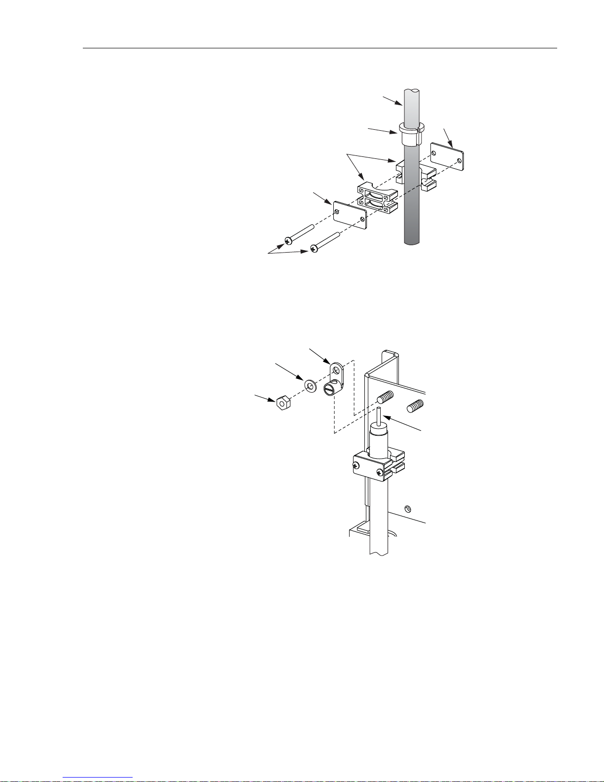
CABLE
ADCP-96-139 • Rev B • July 2017
USE GROMMET
FOR SMALLER
DIAMETER CABLES
CLAMPS
COVER
PLATE
SCREWS
SPACER
21636-B
Figure 18. Cable Clamp Assembly
9. Insert the central strength member into the lug as shown in Figure 19 and then install the
lug on the cable bracket.
LUG
FLAT
WASHER
NUT
CABLE
STRENGTH
MEMBER
22387-B
Figure 19. Strength Member Lug Installation
10. Trim the central strength member to length and tighten the lug set screw.
11. If a grounding kit was installed on the cable, refer to Section 5.3 for the cable grounding
procedure. If a grounding kit was not installed on the cable, refer to Section 5.4 for the
feeder cable splicing procedure.
© 2017, ADC Telecommunications, Inc.
Page 23
Page 30
ADCP-96-139 • Rev B • July 2017
5.3 Grounding the Feeder Cable
If the feeder cable is constructed with a metallic shield or other metallic components, a
grounding kit must be installed on the cable. Use the following procedure for grounding a
feeder cable that has been fitted with a grounding kit:
1. Connect a #6 AWG stranded copper jumper wire (terminated with ring terminals) to the
feeder cable grounding stud.
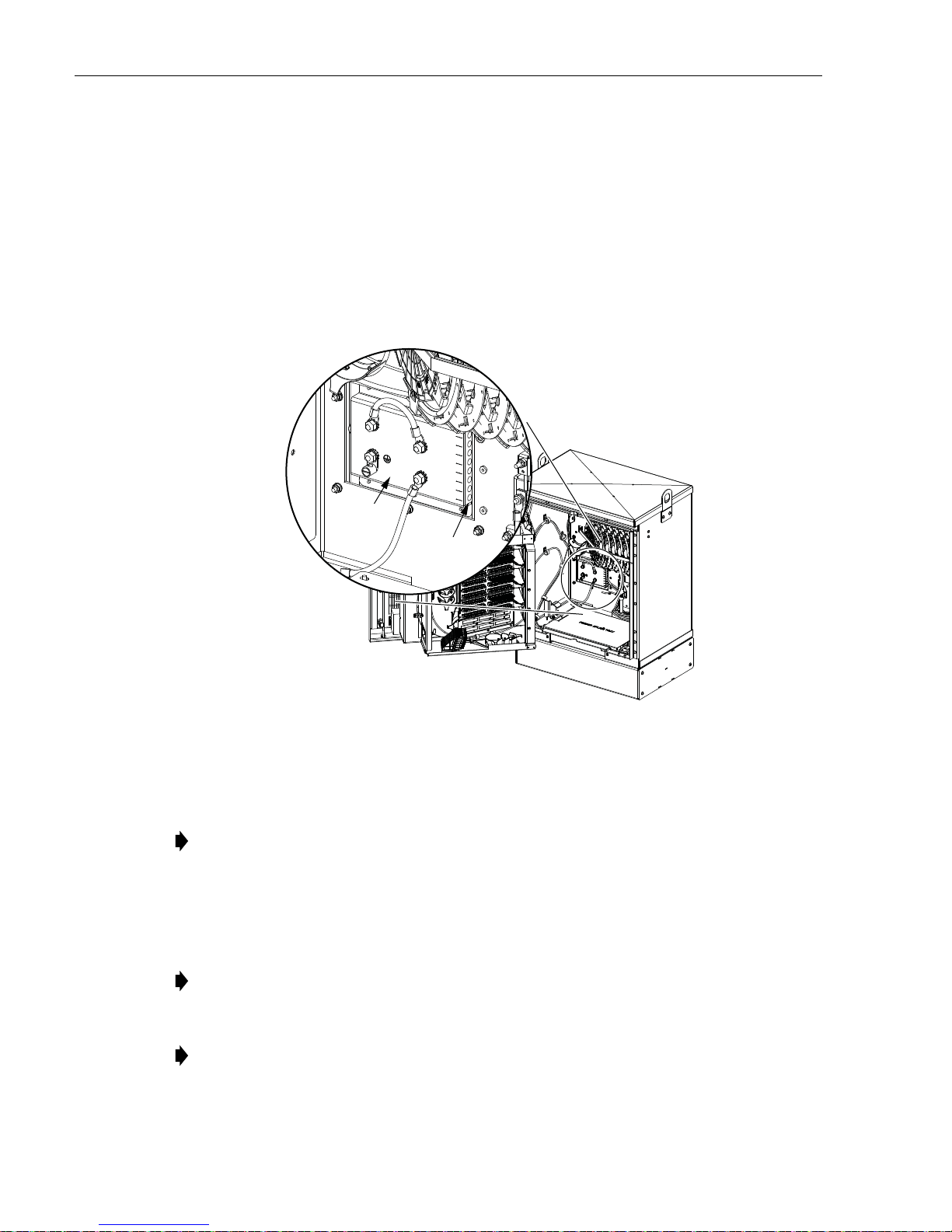
2. Locate the weather-seal strip attached to the right side of the cabinet grounding system as
shown in Figure 20.
CABINET
GROUNDING
SYSTEM
WEATHER-
SEAL STRIP
22685-A
Figure 20. Cable Grounding System - Interior View
3. Route the feeder cable jumper wire to the weather-seal strip as shown in Figure 21 and
push the free end of the wire through the hole that corresponds to cable 8.
Note: The fiber optic cables are numbered 1 – 8 starting with the first cable on the right
side of the cable bracket. The holes for the grounding cables are numbered 1 – 8 starting
with the top opening in the weather-seal strip.
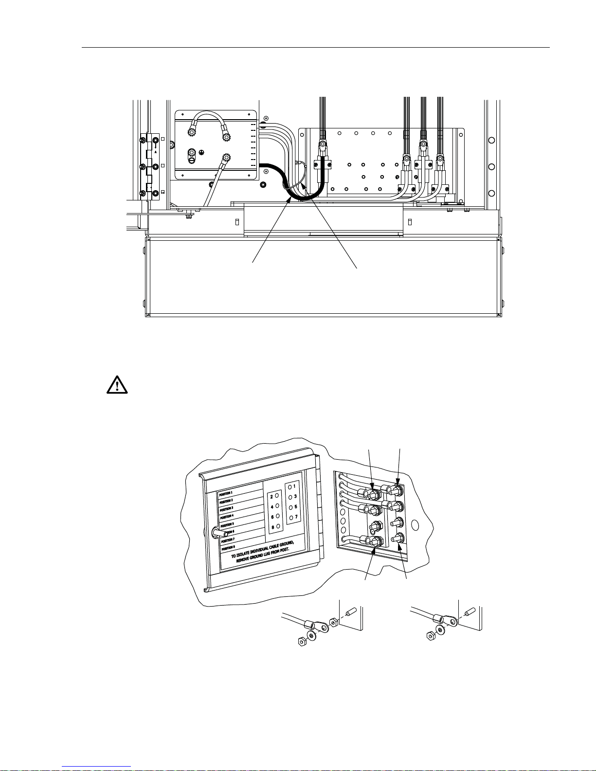
4. Open the grounding system access cover located on rear of cabinet (Figure 22).
5. Identify the grounding stud for cable #8.
Note: A label on the back of the access cover indicates the grounding stud numbers.
6. Connect the grounding jumper wire to grounding stud #8.
Note: Each grounding stud on the left bus bar is equipped with two nuts. When connecting
a jumper wire to the left bus bar, place the cable terminal between the two nuts.
7. Tighten the grounding stud nut to 30 to 35 lbs force-inches. (3.4 to 4.0 Nm) of torque.
Page 24
© 2017, ADC Telecommunications, Inc.
Page 31
ADCP-96-139 • Rev B • July 2017
1
2
3
4
5
6
7
8
12345678
GROUNDING WIRE
FOR FEEDER CABLE
22694-B
SECURE GROUNDING WIRES TO
CABLE BRACKET WITH CABLE TIE
Figure 21. Route Grounding Cable to Grounding System
Warning: The grounding cables ar e connected to cabinet ground through the copp er grounding
blocks. Failure to properly tighten the nut on each individual cable grounding stud could result
in improper grounding of the cable and result in performance or safety issues.
CABLE 1CABLE 2
TIGHTEN TO 30 TO 35
LBS FORCE - INCHES
(3.4 TO 4.0 Nm) OF TORQUE
LEFT BUS BAR
CABLE ASSEMBLY
CABLE 7CABLE 8
21687-A
RIGHT BUS BAR
CABLE ASSEMBLY
Figure 22. Cable Grounding System - Exterior View
Page 25
© 2017, ADC Telecommunications, Inc.
Page 32

ADCP-96-139 • Rev B • July 2017
8. Close the cable grounding system access door and secure using the 216B tool.
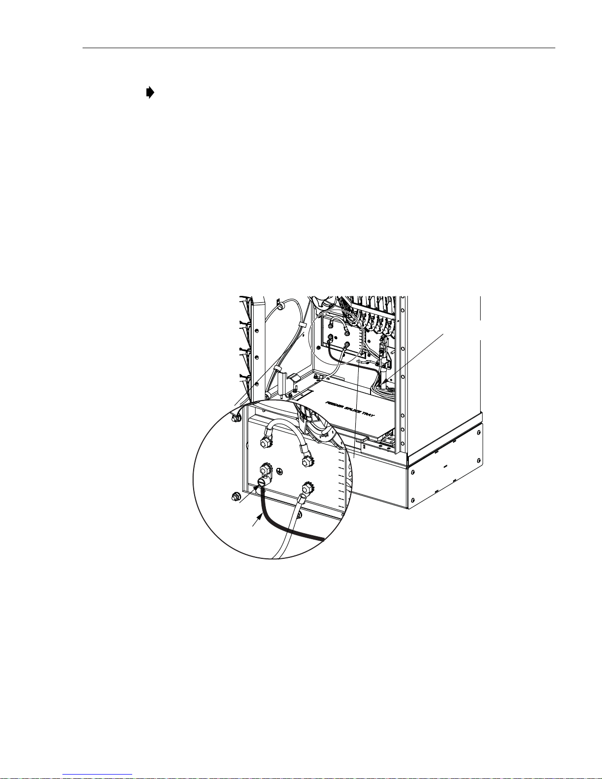
5.4 Splicing the Feeder Cable Fibers
Depending on the option ordered, the cabinet may be equipped with either one or two splice
trays for feeder cable splicing. Use the following procedure to route the feeder cable fibers to
the splice trays and to splice the feeder cable fibers to the splitter input fibers:
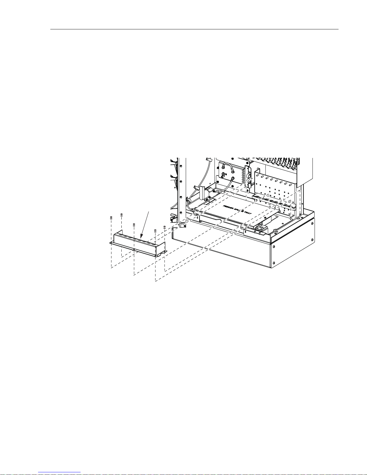
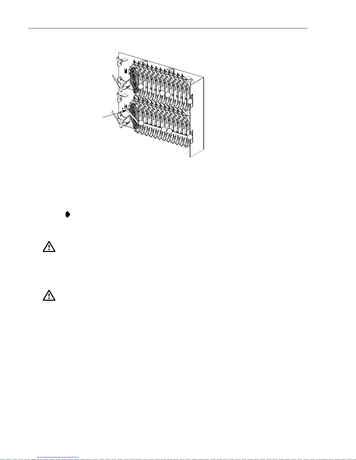
1. Locate the feeder splice tray which is mounted at the bottom of the cabinet, as shown in
Figure 23, and locate the splitter input fibers which are routed to the feeder splice tray.
SPLITTER
FIBERS
COMMON
TIE POINT
FEEDER CABLE
FIBERS
FEEDER SPLICE
TRAY ASSEMBLY
NOTE: SHOWN WITH CABINET REMOVED
TO ALLOW VIEWING OF FIBER ROUTING
22692-A
Figure 23. Feeder Splice Tray and Feeder/Splitter Fiber Routing
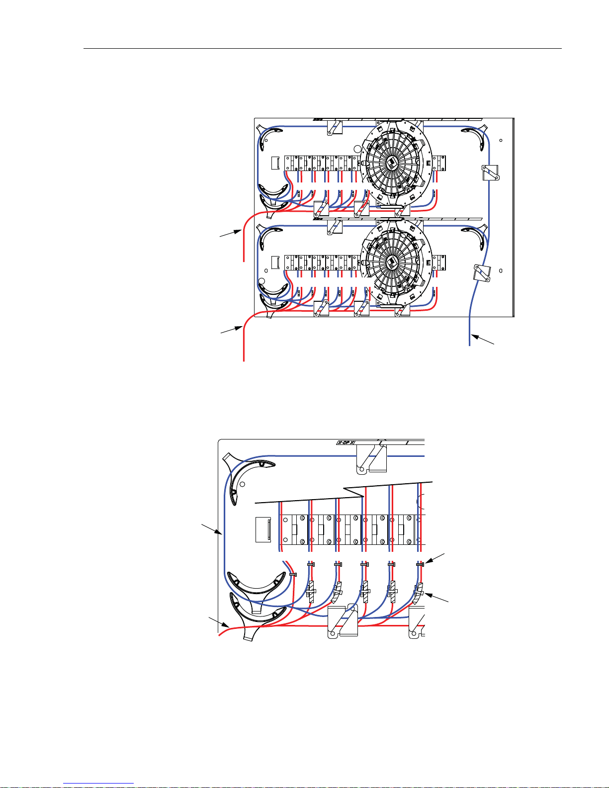
2. Lift the sheet metal cover away from the splice tray holder as shown in Figure 24.
3. Unfasten the hook and pile strips that secure the tray in place and unwind the attached
splitter fibers from around the splice tray assembly.
4. Beginning at the feeder cable subunit breakout point shown in Figure 25, route the feeder
cable fibers to the intersect point with the splitter fibers.
Caution: Always allow sufficient fiber length to permit routing without severe bends. Non bendoptimized fibers may be permanently damaged if bent/curved to a radius of less than 1.5 inches
(3.81 cm).
Page 26
© 2017, ADC Telecommunications, Inc.
Page 33

ADCP-96-139 • Rev B • July 2017
22404-A
SHEET METAL
COVER
SPLICE TRAY
HOLDER
SPLITTER FIBERS
(PRE-INSTALLED)
SPLICE
TRAY
FEEDER CABLE
SUBUNIT BREAKOUT
NOTE: SHOWN WITH CABINET AND SWING
FRAME REMOVED TO ALLOW VIEWING OF
FIBER ROUTING
22693-A
SPLITTER
SUBUNIT
ROUTING
FEEDER
SUBUNIT
ROUTING
SPLICE
TRAY
COVER
COMMON
TIE POINT
Figure 24. Feeder Splice Tray Assembly
Figure 25. Feeder Fiber Routing To Splice Tray
© 2017, ADC Telecommunications, Inc.
Page 27
Page 34

ADCP-96-139 • Rev B • July 2017
5. Create a common tie point by securing the feeder cable subunits (use lacing or cable ties)
to the splitter subunits at the intersect point.
6. Route the feeder cable subunits to the splice tray and then remove the clear plastic cover
from the splice tray.
7. Use lacing or cable ties to secure the feeder cable subunits to the splice tray and verify that
the feeder subunits are the same length as the attached splitter subunits. Adjust as needed
to make the lengths equal.
Caution: Improper handling can damage fiber optic cables. Do not over tighten cable ties or
lacing as this can cause damage or attenuation. Do not compress the fibers or allow them to kink.
8. From the tie point on the splice tray, trim the feeder cable fibers to a cut length of 28
inches (71 cm) and the splitter fibers to a cut length of 36 inches (92 cm).
9. Within the splice tray, remove the subunit tubes from the feeder cable fibers to expose the
bare individual optical fibers.
10. Splice the feeder cable fibers to the appropriate splitter fibers as specified by local policies
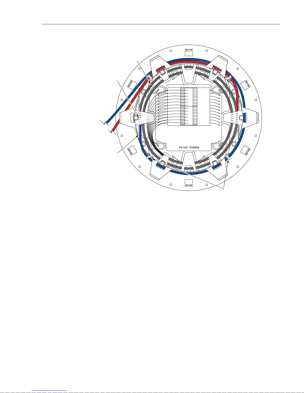
and procedures. Adjust and route the fibers within the splice tray as shown in Figure 26.
Refer to Table 3 for the splitter fiber designations.
11. After splicing is completed, re-install the clear plastic cover on the splice tray.
FEEDER CABLE
TIE POINT
SPLITTER
FIBERS
TIE POINT
12. To replace the splice tray, route the attached subunits (there should be two service loops)
FIBER
BREAKOUT
POINT
NOTE: USE LACING
TO SECURE FIBER
SUBUNITS TO TRAY
SPLITTER FIBERS
(36 INCHES / 92 CM)
FEEDER CABLE FIBERS
(28 INCHES / 71 CM)
22447-A
Figure 26. Stranded Fiber Splice Tray - Feeder Cable Splicing
around the splice tray holder radius limiters as shown in Figure 27 Avoid twisting or
kinking the fiber subunit tubes. Maintain a 1.5-inch (3.81 cm) minimum bend radius for all
non bend-optimized fiber.
13. Secure the splice tray to the splice tray holder using the hook and pile strips.
14. Re-install the sheet metal cover on the splice tray holder.
Page 28
© 2017, ADC Telecommunications, Inc.
Page 35

ADCP-96-139 • Rev B • July 2017
Table 3. Splitter and Spare Fiber Port Designations for 12-, 24-, and 48-Fiber Feeder Cables
SUBUNIT FIBER
1 (Blue) 1 –
2 (Orange) 2 – 2 (Orange) – 26
3 (Green) 3 – 3 (Green) – 27
4 (Brown) 4 – 4 (Brown) – 28
5 (Slate) 5 – 5 (Slate) – 29
6 (White) 6 – 6 (White) – 30
1
7 (Red) 7 – 7 (Red) – 31
(12-, 24-,
or 48-
fiber
cable)
8 (Black) 8 – 8 (Black) – 32
9 (Yellow) 9 – 9 (Yellow) – 33
10 (Violet) 10 – 10 (Viol et) – 34
11 (Rose) 11 – 11 (Rose) – 35
12 (Aqua) 12 – 12 (Aqua) – 36
1 (Blue) 13 –
2 (Orange) 14 – 2 (Orange) – 38
3 (Green) 15 – 3 (Green) – 39
4 (Brown) 16 – 4 (Brown) – 40
5 (Slate) 17 – 5 (Slate) – 41
6 (White) 18 – 6 (White) – 42
2
7 (Red) 19 – 7 (Red) – 43
(24- or
48-fiber
cable)
8 (Black) 20 – 8 (Black) – 44
9 (Yellow) 21 – 9 (Yellow) – 45
10 (Violet) 22 – 10 (Viol et) – 46
11 (Rose) – 23 11 (Rose) – 47
12 (Aqua) – 24 12 (Aqua) – 48
SPLITTER
PORT
SPARE
PORT SUBUNIT FIBER
1 (Blue) – 25
3
(48-fiber
cable)
1 (Blue) – 37
4
(48-fiber
cable)
SPLITTER
PORT
SPARE
PORT
COIL ONE SERVICE
LOOP AROUND
RADIUS LIMITERS
START ROUTING
AT THIS POINT
HOOK AND PILE
STRAPS
22412-A
Figure 27. Feeder Splice Tray Replacement
Page 29
© 2017, ADC Telecommunications, Inc.
Page 36

ADCP-96-139 • Rev B • July 2017
6 DISTRIBUTION CABLE INSTALLATION AND SPLICING
This section describes how to install the OSP distribution cables and how to splice the
distribution cable fibers to the distribution panel pigtails.
6.1 Distribution Cable Installation
The OSP distribution cables enter/exit the cabinet from the bottom. At the entry/exit point to the
cabinet, the each cable is secured with two clamps. Beyond the clamps, the outer sheath of the
cable is removed to expose the optical fibers. Distribution cables are typically 72- or 144-fiber
cable with stranded construction. Blocking and/or grounding kits should be installed (per local
practice) to protect the exposed optical fibers. From the clamping point, the optical fibers are
routed to the splice trays for splicing to the distribution panel pigtails. A lug for securing cable
strength members is provided with the cabinet
Use the following procedure to install each distribution cable:
1. Remove the cable bracket cover (if not already removed) from the cabinet as described in
Section 5.2 to allow installation of the OSP cables. Then return to step 2 of this procedure
to complete installation of the distribution cable.
2. Route the distribution cable into the cabinet from the bottom. If the cabinet is mounted on
a concrete pad, use the duct on the right side.
3. Pull the cable up through the cabinet and strip off 17 feet (6.1 m) of the outside cable
sheath to expose the fiber subunits.
4. Install breakout/blocking and grounding kits as required by local practice. Follow the
installation instructions provided with each kit.
Note: If a grounding kit is required, strip the cable sheath to the recommended length and
install the grounding clamp prior to securing the cable to the cabinet.
5. Locate the cable clamping positions specified for securing the distribution cables to the
cable bracket as shown in Figure 28.
Note: Use cable positions 3 and 5 for distribution ca bles that are greater than 0.8 inches in
diameter that require large size cable clamps.
6. Locate the clamps, grommets, cover plates, and screws that are provided for securing the
cable to the cabinet.
Note: Two large cable clamps (for cables 0.8 inches or more in diameter) are provided for
securing the distribution cable to the cabinet. Additional cable clamps must be ordered
separately if more than one distribution cable will be installed or if small cable clamps (for
cables smaller than 0.8 inches in diameter) are required. If additional large cable clamps
are required, order kit FD3-ACCLGCLMP. If small cable clamps are required, order kit
FD3-ACCSMCLMP.
7. Assemble each pair of clamps (and grommet if required) on the cable as shown in
Figure 29 and secure the cable to the cabinet at the selected cable clamping position.
Page 30
© 2017, ADC Telecommunications, Inc.
Page 37

ADCP-96-139 • Rev B • July 2017
1
2
3
4
5
6
7
FEEDER CABLE
POSITION (8)
DISTRIBUTION
CABLES POSITONS
(1 - 7)
22415-A
REMOVE CUTOUT
TO FIT CABLE
123
4
56
78
HOLES FOR
POSITION 5
LARGE CLAMP
HOLES FOR
POSITION 3
LARGE CLAMP
FRONT VIEW OF CABLE BRACKET
USE THE LARGE CABLE CLAMP
FOR CABLES THAT ARE GREATER
THAN 0.8 INCHES IN DIAMETER
Figure 28. Secure Distribution Cable to Cable Bracket
Note: Rubber plugs are inserted into the cable bracket holes to prevent insects from
entering the cabinet. Remove only those rubber plugs necessary to allow installation of the
distribution cable clamps. All other plugs should be left in place.
CABLE
USE GROMMET
FOR SMALLER
DIAMETER CABLES
CLAMPS
SCREWS
COVER
PLATE
Figure 29. Cable Clamp Assembly
SPACER
21636-B
© 2017, ADC Telecommunications, Inc.
Page 31
Page 38

ADCP-96-139 • Rev B • July 2017
NUT
FLAT
WASHER
LUG
CABLE
STRENGTH
MEMBER
22417-A
8. If the cable has a central strength member, locate the lug that is provided for clamping the
strength member to the cable bracket. If the cable does not have a central strength mem ber,
proceed to step 11.
9. Insert the central strength member into the lug as shown in Figure 19 and then install the
lug on the cable bracket.
Figure 30. Strength Member Lug Installation
10. Trim the central strength member to length and tighten the lug set screw.
11. If a grounding kit was installed on the cable, refer to Section 6.2 for the cable grounding
procedure. If a grounding kit was not installed on the cable, refer to Section 6.3 for the
feeder cable splicing procedure.
6.2 Grounding the Distribution Cables
If a distribution cable is constructed with a metallic shield or other metallic components, then a
grounding kit must be installed on the cable. The grounding kit should provide a stud for
attaching a #6 AWG copper jumper wire to the distribution cable. Use the following procedure
for grounding a distribution cable that has been fitted with a grounding kit:
1. Connect a #6 AWG stranded copper jumper wire (terminated with ring terminals) to the
distribution cable grounding stud.
2. Locate the weather-seal strip attached to the right side of the cabinet grounding system as
shown in Figure 31.
3. Route the distribution cable jumper wire to the weather-seal strip as shown in Figure 31
and push the free end of the wire through the hole that corresponds to the cable mounting
position.
Page 32
© 2017, ADC Telecommunications, Inc.
Page 39

ADCP-96-139 • Rev B • July 2017
1
2
3
4
5
6
7
8
12345678
GROUNDING WIRE
FOR DISTRIBUTION
CABLE #1
22695-B
SECURE GROUNDING WIRES TO
CABLE BRACKET WITH CABLE TIE
Note: The fiber optic cables are numbered 1 – 8 starting with the first cable on the right
side of the cable bracket. The holes for the grounding cables are numbered 1 – 8 starting
with the top opening in the weather-seal strip.
CABINET
GROUNDING
SYSTEM
WEATHER-
SEAL STRIP
22685-A
4. Open the grounding system access cover located at the rear side of the cabinet as shown in
Figure 32.
Figure 31. Route Grounding Cable to Grounding System
© 2017, ADC Telecommunications, Inc.
Page 33
Page 40

ADCP-96-139 • Rev B • July 2017
5. Identify the grounding stud that corresponds to the cable mounting position.
Note: A label on the back of the access cover indicates the grounding stud numbers.
CABLE 1CABLE 2
CABLE 7CABLE 8
TIGHTEN TO 30 TO 35
LBS FORCE - INCHES
(3.4 TO 4.0 Nm) OF TORQUE
LEFT BUS BAR
CABLE ASSEMBLY
RIGHT BUS BAR
CABLE ASSEMBLY
21687-A
Figure 32. Cable Grounding System - Exterior View
6. Connect the grounding jumper wire to the appropriate cable grounding stud.
Note: Each grounding stud on the left bus bar is equipped with two nuts. When connecting
a jumper wire to the left bus bar, place the cable terminal between the two nuts.
7. Tighten the grounding stud nut to 30 to 35 lbs force-inches. (3.4 to 4.0 Nm) of torque.
Warning: The grounding ca bles are connected to cabinet ground th rough the copper grounding
blocks. Failure to properly tighten the nut on each individual cable grounding stud could result
in improper grounding of the cable and result in performance or safety issues.
8. Close the cable grounding system access door and secure using the 216B tool.
Page 34
© 2017, ADC Telecommunications, Inc.
Page 41

6.3 Splicing the Distribution Cable Fibers
DISTRIBUTION
SPLICE WHEEL
ASSEMBLY
NOTE: SHOWN WITH CABINET REMOVED
TO ALLOW VIEWING OF FIBER ROUTING
22696-A
DISTRIBUTION CABLE
SUBUNITS ROUTED
TO SPLICE WHEELS
DISTRIBUTION PANEL
SUBUNITS ROUTED
TO SPLICE WHEELS
Depending on the option ordered, the cabinet may be equipped with up to 24 splice wheels for
distribution cable splicing. Use the following procedure to route the distribution cable fibers to
the splice trays and to splice the distribution cable fibers to the distribution panel pigtails:
1. Identify and locate the distribution panel subunits that are routed from the back of each
panel to the splice wheels as shown in Figure 33.
2. Unfasten the hook and pile strip that secures the top row of splice wheels to the back of the
cabinet. Rotate the splice wheels outward so the distribution panel fibers and cable rings
are visible.
3. Refer to Figure 34 to identify and locate the splice wheels for distribution panel #1.
Note: The pigtails from each distribution panel are grouped into six 12-fiber subunits and
each subunit is routed to a splice wheel. The subunits are numbered from 1 – 24 and the
individual fibers are numbered from 1 – 288. The splice wheels are arranged from left to
right starting at the top and are labeled with the individual fiber/port numbers.
ADCP-96-139 • Rev B • July 2017
Figure 33. Distribution Splice Wheels and Distribution Panel Subunit Routing
Page 35
© 2017, ADC Telecommunications, Inc.
Page 42
ADCP-96-139 • Rev B • July 2017
1
7
6
12
13
18
19
24
HOOK AND
PILE STRIP
SUBUNITS PANEL FIBERS
1 - 6 1 1 - 72
7 - 12 2 73 - 144
SUBUNITS PANEL FIBERS
13 - 18 3 145 - 216
19 - 24 4 217 - 288
22697-A
Figure 34. Distribution Splice Wheel Assembly
4. Beginning at the distribution cable fiber breakout point, route each distribution cable
subunit to the tie point below the appropriate splice wheel as shown in Figure 35.
Note: Each distribution panel subunit is secured to the cabinet at a point just below a
splice wheel. Spiral wrap is placed over the subunit at the tie point to prevent the cable tie
from compressing the fiber within the subunit.
Caution: Always allow sufficient fiber length to permit routing without severe bends. Non bendoptimized fibers may be permanently damaged if bent/curved to a radius of less than 1.5 inches
(3.81 cm).
5. Use cable ties or lacing to loosely secure each distribution fiber subunit to the appropriate
distribution panel subunit at a point just above the spiral wrap as shown in Figure 36.
Caution: Improper handling can damage fiber optic cables. Do not over tighten cable ties or
lacing as this can cause damage or attenuation. Do not compress the fibers or allow them to kink.
Page 36
© 2017, ADC Telecommunications, Inc.
Page 43
ADCP-96-139 • Rev B • July 2017
NOTE: SHOWN WITH MOST OF THE SPLICE WHEELS
REMOVED TO ALLOW VIEWING OF SUBUNIT ROUTING
DISTRIBUTION
PANEL 1 AND 2
SUBUNITS 1 - 12
FIBERS 1 - 144
DISTRIBUTION
PANEL 3 AND 4
SUBUNITS 13 - 24
FIBERS 145 - 288
1
13
141516 17 18
762345 12
19
24
Figure 35. Distribution Cable Subunit Routing to Splice Wheel s
NOTE: SHOWN WITH SPLICE WHEELS REMOVED
TO ALLOW VIEWING OF SUBUNIT TIE POINTS
22698-A
DISTRIBUTION
CABLE
SUBUNITS
DISTRIBUTION
CABLE SUBUNITS
DISTRIBUTION
PANEL SUBUNITS
6. Remove the splice wheel for fibers/ports 1-12 from the cabinet and carefully unwind the
the distribution panel subunit (uncoil to full length) that is coiled around the wheel.
LOOSELY SECURE DISTRIBUTION
CABLE AND DISTRIBUTION PANEL
SUBUNITS TOGETHER AT A POINT
JUST ABOVE THE SPIRAL WRAP
1
45
623
FACTORY INSTALLED
CABLE TIES OVER
SPIRAL WRAP
22449-A
Figure 36. Securing the Distribution Cable Subunits
© 2017, ADC Telecommunications, Inc.
Page 37
Page 44

ADCP-96-139 • Rev B • July 2017
7. Starting at the common tie point below the splice wheel, route the distribution cable
subunit to the splice wheel. Make sure the distribution cable subunit and distribution panel
subunit are same length as shown in Figure 37.
Figure 37. Equalize the Distribution Panel and Distribut ion Cable Subunit Lengths
8. Coil the distribution subunit once around th e splice wheel and then mark the fiber breakout
point (see Figure 37) on the outside of the subunit protective jacket.
9. From the point marked in step 8, trim the distribution cable breakout fibers to a breakout
length of 37 inches (94 cm).
10. Starting at the breakout mark, remove the protective jacket to expose the distribution cable
subunit fibers.
11. Remove the top cover from the splice wheel.
12. Secure the distribution cable subunit to the splice wheel at the points specified in
Figure 38.
13. Adjust the distribution cable subunit so the fiber breakout is positioned at the specified
point (see Figure 38).
Page 38
© 2017, ADC Telecommunications, Inc.
Page 45
ADCP-96-139 • Rev B • July 2017
TOP SIDE
FIBER BREAKOUT
POINT
MAKE LOOP AS
LARGE AS POSSIBLE TO
ENSURE MAXIMUM
FIBER STORAGE
DISTRIBUTION
CABLE
SUBUNIT
DISTRIBUTION
PANEL
SUBUNIT
ROUTE TO
INSIDE OF TRAY
DISTRIBUTION CABLE
SUBUNIT TIE POINTS
22429-A
ROUTE FIBERS 2 TIMES
AROUND INSIDE OF TRAY
Figure 38. Installing Distribution Cable Subunit In Splice Wheel
14. Route the breakout fibers at least two times around the inside of the wheel making the loop
as large as possible to ensure maximum fiber storage.
15. Splice the distribution panel fibers to the distribution cable fibers in accordance with local
policies and procedures.
16. Replace the splice wheel top cover and then turn the splice wheel in a clockwise direction
to roll up the excess slack as shown in Figure 39
© 2017, ADC Telecommunications, Inc.
Page 39
Page 46
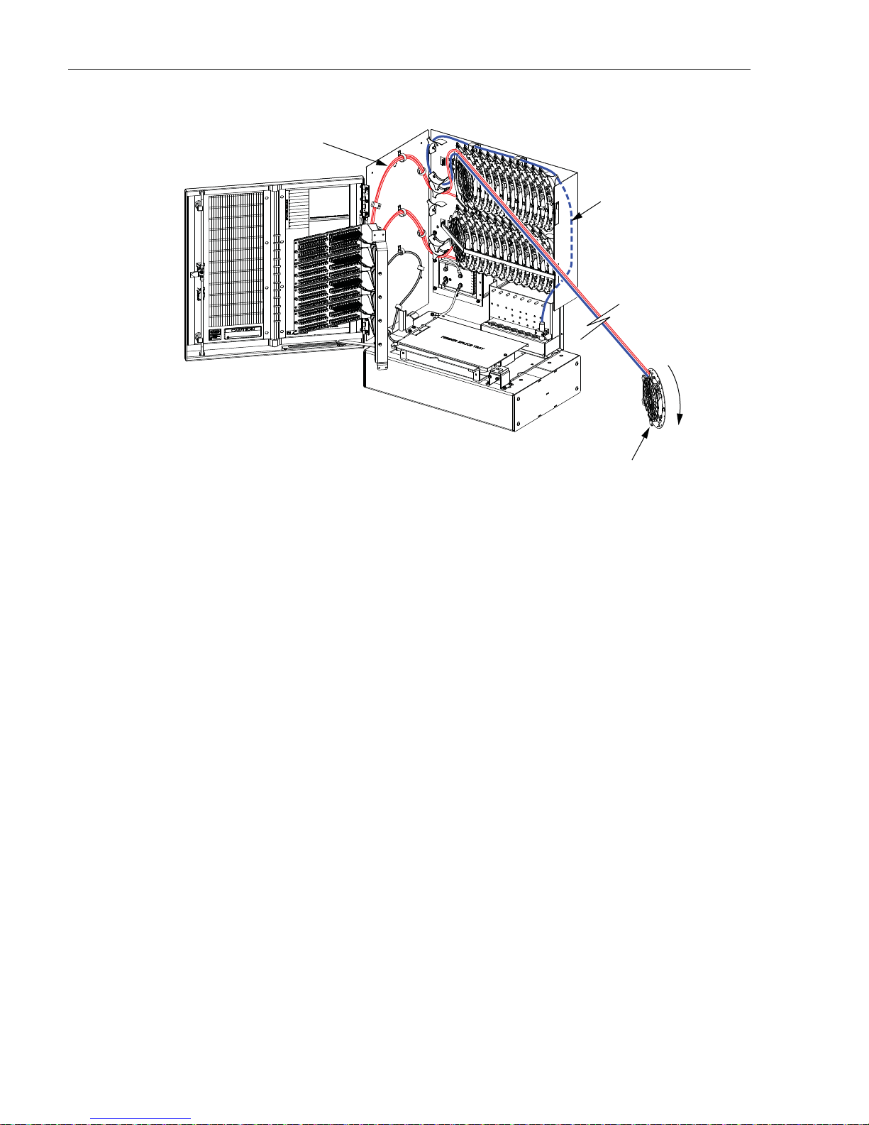
ADCP-96-139 • Rev B • July 2017
NOTE: SHOWN WITH CABINET AND
SWING FRAME REMOVED TO ALLOW
VIEWING OF FIBER ROUTING
DISTRIBUTION PANEL
SUBUNIT ROUTING
22699-A
SPLICE TRAY #1
OF 24
DISTRIBUTION CABLE
SUBUNIT ROUTING
ROTATE CLOCKWISE
TO STORE SLACK
Figure 39. Store Excess Slack
17. When all the excess slack is stored on the splice wheel, re insert the splice wheel into the
original mounting slot.
18. Repeat this procedure for each distribution cable subunit.
19. When all splicing is completed, use the hook and pile straps to secure the rows of splice
wheels in the closed position.
20. Reinstall the cable bracket cover as described in Section 5.1 when all the distribution
cables have been installed and spliced.
21. Designation labels are provided on the front door of the cabinet for recording subscriber
information. For each optical port, indicate the subscriber address and service information.
Page 40
© 2017, ADC Telecommunications, Inc.
Page 47
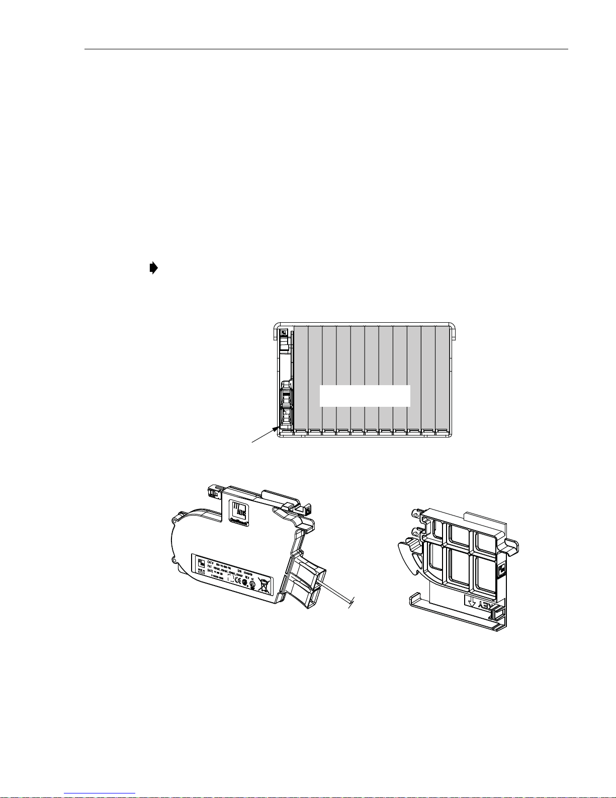
7 PLUG AND PLAYER SPLITTER MODULE INSTALLATION
SPLITTER
INSTALLED
IN SLOT 1
22701-A
DUST CAP ASSEMBLY
(INSTALLED IN EMPTY
SPLITTER SLOTS)
PLUG AND PLAY
SPLITTER
12111098765432
1
SLOT NUMBERS SHOWN
FOR REFERENCE ONLY
The 288 cabinet can accommodate up to 12 splitter modules. Plug and play splitter modules are
equipped with either one or two input connectors. Inserting the splitter into the splitter
compartment connects the splitter input connector(s) to the feeder cable connector(s). The
splitter output fibers may be stored for later use or routed to the distribution panels for
connection to the distribution ports. Additional instructions for installing plug and play splitter
modules are provided in the FDH 3000 Plug and Play Splitter Installation Guide (ADCP-96-
087). Use only splitters equipped with bend-optimized fibers.
Use the following procedure to install additional splitters in the cabinet:
1. Locate the next available splitter mounting position as shown in Figure 40.
Note: Install splitters in the order shown, beginning on the left side of the splitter
compartment and then working toward the right.
2. Remove the dust cap assembly from the selected splitter slot.
ADCP-96-139 • Rev B • July 2017
3. Remove the corresponding feeder cable connector(s) from the rear of the splitter
compartment as shown in Figure 41.
Figure 40. Splitter Module Installation
© 2017, ADC Telecommunications, Inc.
Page 41
Page 48

ADCP-96-139 • Rev B • July 2017
CONNECTOR
KEYWAY
REAR VIEW OF
SPLITTER COMPARTMENT
22686-A
Warning: Infrared radiation is invisible and can seriously dama ge the retina of the eye. Do no t
look into the ends of any optical fiber. Do not look directly into the optical adapters or
connectors. Exposure to invisible laser radiation may result. An optical power meter should be
used to verify active fibers. A protective cap or hood MUST be immediately placed over any
radiating adapter or optical connector to avoid the potential of dangero us amounts of radiation
exposure. This practice also prevents dirt particles from entering the adapter or connector.
Figure 41. Feeder Cable Connector - Typical Compartment Shown
4. Clean the feeder cable connector(s) as specified in the Optical Fiber Systems Cleaning and
Mating Instructions (ADCP-90-159).
5. Reinstall the feeder cable connector(s) at the rear of the splitter compartment.
6. Insert the splitter into the mounting slot as shown in Figure 42.
7. Route the splitter output fibers to the connector storage panel or to the designated
subscriber port. Refer to Section 8 for the routing procedure.
8. Designation labels are provided on the front door of the cabinet for recording splitter
information. For each splitter, indicate the splitter type and related service information.
Page 42
© 2017, ADC Telecommunications, Inc.
Page 49

Figure 42. Splitter Installation
22703-A
SPLITTER
ADCP-96-139 • Rev B • July 2017
8 ROUTING AND CONNECTING THE SPLITTER OUTPUT FIBERS
The splitter modules are mounted at the top of the 288 cabinet. When a splitter module is
initially installed, the output fibers are routed to the storage panel located at the bottom of the
cabinet. At the storage panel, the output fibers are temporarily “parked” until they are needed.
Service to a subscriber is enabled by removing an unu sed output fiber from the storage panel,
routing it to the appropriate distribution panel, and then connecting it to the subscriber port.
8.1 Storing The Splitter Output Fibers
Use the following procedure to store the splitter output fibers.
1. Following installation of a splitter module, locate an open connector pack slot in the
storage panel at the bottom of the cabinet.
2. Insert the connector pack into the unused slot in the storage panel. Refer to the FDH 300 0
Plug and Play Splitter Installation Guide (ADCP-96-087) provided with splitter modules
for additional information on installing connector packs in the storage panel.
3. Use the radius limiters on the right side of the cabinet to store any excess fiber slack. Refer
to Figure 43 for the routing guidelines.
© 2017, ADC Telecommunications, Inc.
Page 43
Page 50

ADCP-96-139 • Rev B • July 2017
SPLITTER
COMPARTMENTS
STORAGE
PANELS
RADIUS
LIMITERS
22683-A
CONNECTOR
PANELS
8.2 Enabling Service To a Subscriber
Use the following procedure to enable service to a subscriber:
1. Check the designation labels on the cabinet doors to determine the distribution panel and
port number that corresponds to the address of the subscriber.
2. Locate the subscriber port on the specified distribution panel and remove both the adapter
dust cap and the connector ferrule dust cap.
3. Select and remove an unused splitter output fiber from the storage panel and carefully
work it free of any other fibers.
Warning: Infrared radiation is invisible and can seriously dama ge the retina of the eye. Do no t
look into the ends of any optical fiber. Do not look directly into the optical adapters or
connectors. Exposure to invisible laser radiation may result. An optical power meter should be
used to verify active fibers. A protective cap or hood MUST be immediately placed over any
radiating adapter or optical connector to avoid the potential of dangero us amounts of radiation
exposure. This practice also prevents dirt particles from entering the adapter or connector.
4. Remove the ferrule dust cap from the connector and then clean the connector as specified
in the Optical Fiber Systems Cleaning and Mating Instructions (ADCP-90-159).
5. Connect the splitter output fiber connector to the subscriber port.
6. Use the radius limiters on the right side of the cabinet to store any excess fiber slack. Refer
to Figure 43 for the routing guidelines
Figure 43. Routing Splitter Output Fibers
Page 44
© 2017, ADC Telecommunications, Inc.
Page 51

9 PASS-THROUGH ROUTING PROCEDURES
PULL UPWARD ON TAB
REMOVE DUST CAP
21509-B
Pass-through routing is used when it is necessary for a feeder cable optical signal to be routed
directly to a distribution port. This involves connecting a patch cord between the terminated
feeder cable connector and the appropriate distribution port. Because feeder cable fibers can be
terminated at either the sliding adapter pack or the splitter compartment, two pass-through
routing procedures are provided.
9.1 Sliding Adapter Pack Pass-Through Routing Procedure
Use the following procedure to route a jumper patch cord between the feeder cable sliding
adapter pack and one of the distribution panels.
1. Locate the appropriate feeder cable connector on the sliding adapter pack.
2. Pull upward on the small tab on top of the adapter pack and lift the adapter pack to the
position shown in Figure 44.
ADCP-96-139 • Rev B • July 2017
Warning: Infrared radiation is invisible and can seriously dama ge the retina of the eye. Do no t
look into the ends of any optical fiber. Do not look directly into the optical adapters or
connectors. Exposure to invisible laser radiation may result. An optical power meter should be
used to verify active fibers. A protective cap or hood MUST be immediately placed over any
radiating adapter or optical connector to avoid the potential of dangero us amounts o f radiation
exposure. This practice also prevents dirt particles from entering the adapter or connector.
3. Remove the dust cap from the appropriate bulkhead adapter in the sliding adapter pack.
4. Obtain the optical patch cord (accessory) recommended for the pass-through connection.
Note: Use catalog# FPCFW-APSC-P-2.1M for APC/SC connectors.
Figure 44. Typical Adapter Pack Raised to Access Position
Use catalog# FPCFW-SPSC-P-2.1M for UPC/SC connectors.
Page 45
© 2017, ADC Telecommunications, Inc.
Page 52

ADCP-96-139 • Rev B • July 2017
22706-A
PASS-THROUGH
ROUTING FOR
PATCH CORDS
SLIDING
ADAPTER
PAC K
5. Remove the ferrule dust cap from one of the patch cord connectors and then clean the
connector as specified in the Optical Fiber Connector Wet and Dry Cleaning Instructions
(ADCP-90-159) or by locally approved procedures.
6. Insert the patch cord connector into the bulkhead adapter in the sliding adapter pack.
7. Slide the adapter pack down into the closed position.
8. Route the pass-through patch cord to the front side of the swing-out assembly as shown in
Figure 45.
Figure 45. Routing Pass-Through Patch Cord From Sliding Adapter Pack
9. Locate the distribution panel and the optical port to which the pass-through patch cord is
to be routed.
10. Refer to the procedures in Section 8.2 to route the pass-through patch cord to the
distribution panel and to connect the patch cord connector to the appropriate optical port.
9.2 Splitter Compartment Pass-Through Routing Procedure
Use the following procedure to route a jumper patch cord between the splitter compartment and
one of the distribution cable distribution panels.
1. Locate an open splitter mounting position.
2. Remove the dust cap assembly from the selected splitter slot.
3. Remove the feeder cable connector(s) from the rear of the splitter compartment (see
Page 46
© 2017, ADC Telecommunications, Inc.
Figure 41).
Page 53

ADCP-96-139 • Rev B • July 2017
21365-B
ORIENT CONNECTOR
SO KEY IS ON TOP
Warning: Infrared radiation is invisible and can seriously dama ge the retina of the eye. Do no t
look into the ends of any optical fiber. Do not look directly into the optical adapters or
connectors. Exposure to invisible laser radiation may result. An optical power meter should be
used to verify active fibers. A protective cap or hood MUST be immediately placed over any
radiating adapter or optical connector to avoid the potential of dangero us amounts o f radiation
exposure. This practice also prevents dirt particles from entering the adapter or connector.
4. Clean the feeder cable connector(s) as specified in the Optical Fiber Systems Cleaning and
Mating Instructions (ADCP-90-159).
5. Reinstall the feeder cable connector(s) at the rear of the splitter compartment.
6. Obtain the optical patch cord (accessory) recommended for the pass-through connection.
7. Remove the ferrule dust cap from one of the patch cord connectors and then clean the
connector as specified in the Optical Fiber Connector Wet and Dry Cleaning Instructions
(ADCP-90-159) or by locally approved procedures.
8. Install the patch cord connector in the dust cap assembly as shown in Figure 46.
Note: Two patch cord connectors may be installed in the dust cap assembly if required.
9. Connect the patch cord connector(s) to the feeder cable connector(s) by inserting the dust
cap assembly into the splitter slot as shown in Figure 47.
10. Locate the distribution panel and the optical port to which the pass-through patch cord is
to be routed.
11. Refer to the procedures in Section 8.2 to route the pass-through patch cord to the
distribution panel and to connect the patch cord connector to the appropriate optical port.
Figure 46. Installing Patch Cord Connector in Dust Cap Assembly
Page 47
© 2017, ADC Telecommunications, Inc.
Page 54

ADCP-96-139 • Rev B • July 2017
22705-A
DUST CAP AND
CONNECTOR
ASSEMBLY
Figure 47. Inserting Dust Cap Assembly Into Splitter Comp ar tment
10 MAINTENANCE AND REPAIR PROCEDURES
The 288 cabinet requires no regular maintenance to insure continuous and satisfactory
operation. Maintenance is limited to repairing or replacing any cabinet components that may be
damaged or broken in the course of normal operation. The following sections provide
procedures for repairing or replacing common cabinet components.
10.1 Painting
Brush-in-cap type bottles of paint are available for touching-up nicks and scratches in the
factory coat of paint. Lightly sand the area to be painted and then clean it thoroughly to remove
any dirt, dust, or foreign matter. Shake the paint bottle until thoroughly mixed and then apply a
light coat of paint to the damaged area using the small brush attached to the cap. Wait until the
paint is dry and then apply a second coat if necessary. When finished painting, replace the paint
bottle cap and tighten securely.
10.2 Distribution Panel Adapter Replacement
Replacement adapters are available for the distribution panels. Use the following proced ure to
remove and replace a damaged adapter:
1. Disconnect the splitter connector from the front side of the broken adapter as shown in
Figure 48 and install a dust cap on the connector.
Page 48
© 2017, ADC Telecommunications, Inc.
Page 55

ADCP-96-139 • Rev B • July 2017
DISTRIBUTION
CONNECTOR
SPLITTER
CONNECTOR
METAL TAB
(TOP AND BOTTOM)
ADAPTER
21366-C
NOTE: AFTER REMOVING THE CONNECTOR
FROM THE ADAPTER, INSTALL A DUST CAP
ON THE CONNECTOR TO KEEP THE ENDFACE
CLEAN AND TO PREVENT DAMAGE
Warning: Infrared radiation is invisible and can seriously dama ge the retina of the eye. Do no t
look into the ends of any optical fiber. Do not look directly into the optical adapters or
connectors. Exposure to invisible laser radiation may result. An optical power meter should be
used to verify active fibers. A protective cap or hood MUST be immediately placed over any
radiating adapter or optical connector to avoid the potential of dangero us amounts o f radiation
exposure. This practice also prevents dirt particles from entering the adapter or connector.
Caution: Use e xtreme care when removing a connector or an adapter from the distribution
panel to avoid macro bending the adjacent fibers.
Figure 48. Adapter Removal and Replacement - Typ ical Distribution Panel
2. Unlatch and fully open the cabinet swing frame to provide access to the rear side of the
distribution panel.
3. Disconnect the distribution connector from the rear side of the broken adapter and install a
dust cap on the connector.
4. Working from the rear side of the distribution panel, use the SC adapter removal tool
(catalog # FCC-ACC003) to depress the two metal tabs that retain the adapter in the panel.
Then push forward on the adapter until it pops out of the panel.
5. Discard the damaged adapter.
6. Install the replacement adapter by inserting it into the distribution panel from the front and
then pushing it toward the back until it snaps into place.
Note: Make sure the keyway in the replacement adapter is facing in the same direction as
the keyways in the rest of the adapters installed in the distribution panel.
Page 49
Page 56

ADCP-96-139 • Rev B • July 2017
7. Clean the distribution and splitter fiber connectors as specified in the Optical Fiber
Systems Cleaning and Mating Instructions (ADCP-90-159).
8. Connect the distribution connector to the rear side of the replacement adapter.
9. Close the cabinet swing frame.
10. Connect the splitter connector to the front side of the replacement adapter.
10.3 Splitter Compartment Adapter Replacement
Replacement adapter assemblies are available for the splitter compartment. Use the following
procedure to remove and replace a damaged adapter assembly:
1. Unlatch and fully open the cabinet swing frame to provide access to the both the front and
rear side of the splitter compartment.
2. Remove the splitter or the dust cap assembly from the front side of the broken adapter
assembly.
Warning: Infrared radiation is invisible and can seriously dama ge the retina of the eye. Do no t
look into the ends of any optical fiber. Do not look directly into the optical adapters or
connectors. Exposure to invisible laser radiation may result. An optical power meter should be
used to verify active fibers. A protective cap or hood MUST be immediately placed over any
radiating adapter or optical connector to avoid the potential of dangero us amounts of radiation
exposure. This practice also prevents dirt particles from entering the adapter or connector.
3. Remove the feeder cable connector(s) from the rear side of the broken adapter assembly as
shown in Figure 49 and install a dust cap on the connector(s).
4. Turn the thumb screw on the top of the broken adapter assembly clockwise until the
adapter assembly detaches from the top of the splitter compartment.
5. Discard the damaged adapter assembly.
6. Install the replacement adapter assembly in the splitter compartment and secure it by
turning the thumbscrew counter-clockwise until tight.
7. Clean the feeder cable connector(s) as specified in the Optical Fiber Systems Cleaning and
Mating Instructions (ADCP-90-159).
8. Connect the feeder cable connector to the rear side of the replacement adapter assembly.
9. Connect the dust cap or splitter to the front side of the replacement adapter assembly.
10. Close the cabinet swing frame.
Page 50
© 2017, ADC Telecommunications, Inc.
Page 57

THUMB
SCREW
FEEDER CABLE
CONNECTOR
ADCP-96-139 • Rev B • July 2017
DUST CAP
OR SPLITTER
ADAPTER
ASSEMBLY
REAR VIEW OF
SPLITTER COMPARTMENT
Figure 49. Splitter Compartment Adapter Replacement - Typical Compa rtment
10.4 Replacing a Damaged Fiber or Connector
A damaged fiber or connector can usually be replaced. The following describes the various
replacement options.
• Damaged Splitter Output Fiber: Replace the splitter output fiber from the connector all
the way back into the splitter. Splice a new pigtail (use only pigtails with bend-optimized
fiber) to the remaining section of the old fiber within the splitter chassis. This procedure
requires removing and disassembling the splitter to insert a splice chip and to perform the
splice. A kit is available from ADC. Refer to ADCP-96-034 for the procedure.
• Damaged Distribution or Feeder Connector: Replace the connector at the bulkhead
adapter if just the connector alone is damaged. Use a field-installable connector
replacement kit. Refer to Section 10.4.1 for the replacement procedures.
22688-A
© 2017, ADC Telecommunications, Inc.
Page 51
Page 58

ADCP-96-139 • Rev B • July 2017
10.4.1 Splitter Output Fiber Connector Replacement
Use the following procedure to replace the connector:
1. Disconnect the damaged connector and the good connector from the adapter and install a
dust cap on the good connector.
Warning: Infrared radiation is invisible and can seriously dama ge the retina of the eye. Do no t
look into the ends of any optical fiber. Do not look directly into the optical adapters or
connectors. Exposure to invisible laser radiation may result. An optical power meter should be
used to verify active fibers. A protective cap or hood MUST be immediately placed over any
radiating adapter or optical connector to avoid the potential of dangero us amounts of radiation
exposure. This practice also prevents dirt particles from entering the adapter or connector.
2. Replace the damaged connector as specified in the procedures provided with the fieldinstallable connector replacement kit.
3. Clean both connectors as specified in the Optical Fiber Connector Wet and Dry Cleaning
Instructions (ADCP-90-159) or by locally approved procedures.
4. Reconnect the good connector and the replacement connector to the adapter.
10.5 Door Gasket Replacement
Damaged door gaskets may be replaced using the door gasket kit which includes a ro ll of gasket
material. The ideal installation temperature for the adhesive used on the replacement gaskets is
between 60 and 100 ºF (16 and 38 ºC). Installation is not recommended if the temperature is
below 50 ºF (10 ºC). Remove any damaged sections of gasket material from the door. If
necessary, use a citrus based adhesive cleaner to remove any adhesive that may stay attached to
the door. Cut replacement lengths of gasket material from the roll as needed. Remove the paper
backing to expose the adhesive and then carefully apply the replacement gasket to the door.
Take care not to leave any gaps between the meeting sections of the gasket strips.
10.6 Door Replacement
Damaged cabinet doors may be replaced using the door replacement kit. Use the following
procedure to remove and replace the cabinet doors:
1. Open the cabinet door and lock it in the open position as shown in Figure 50.
2. Use a 3/8-inch nut driver to remove the locking nuts and washers that secure the door
bracket slide to the bottom edge of the door as shown in Figure 51. Save the nuts and
washers for reuse.
3. Use a 3/8-inch nut driver to remove the locking nuts that secure the hinges to the door.
Save nuts for reuse.
Note: Support the door as the last nuts are removed to prevent the door from falling.
Page 52
© 2017, ADC Telecommunications, Inc.
Page 59

ADCP-96-139 • Rev B • July 2017
22684-A
DOOR
HINGES
DOOR BRACKET
SLIDE
GROUNDING
STRAP LUG
Figure 50. Door Replacement
4. Carefully lift the door away from the cabinet.
5. Transfer all designation information that may be recorded on the damaged door to the
labels on the replacement door.
6. Place the replacement door in position for installation on the hinges.
7. Reinstall the locking nuts (saved in step 3) that secure each hinge to the door.
Note: Be sure to re-secure the grounding strap lug (see Figure 50) to the door when
securing the hinges to the door.
8. Secure the door bracket slide to the bottom edge of the door using the locking nuts and
washers saved in step 2.
9. Close door and check for proper operation.
© 2017, ADC Telecommunications, Inc.
Page 53
Page 60
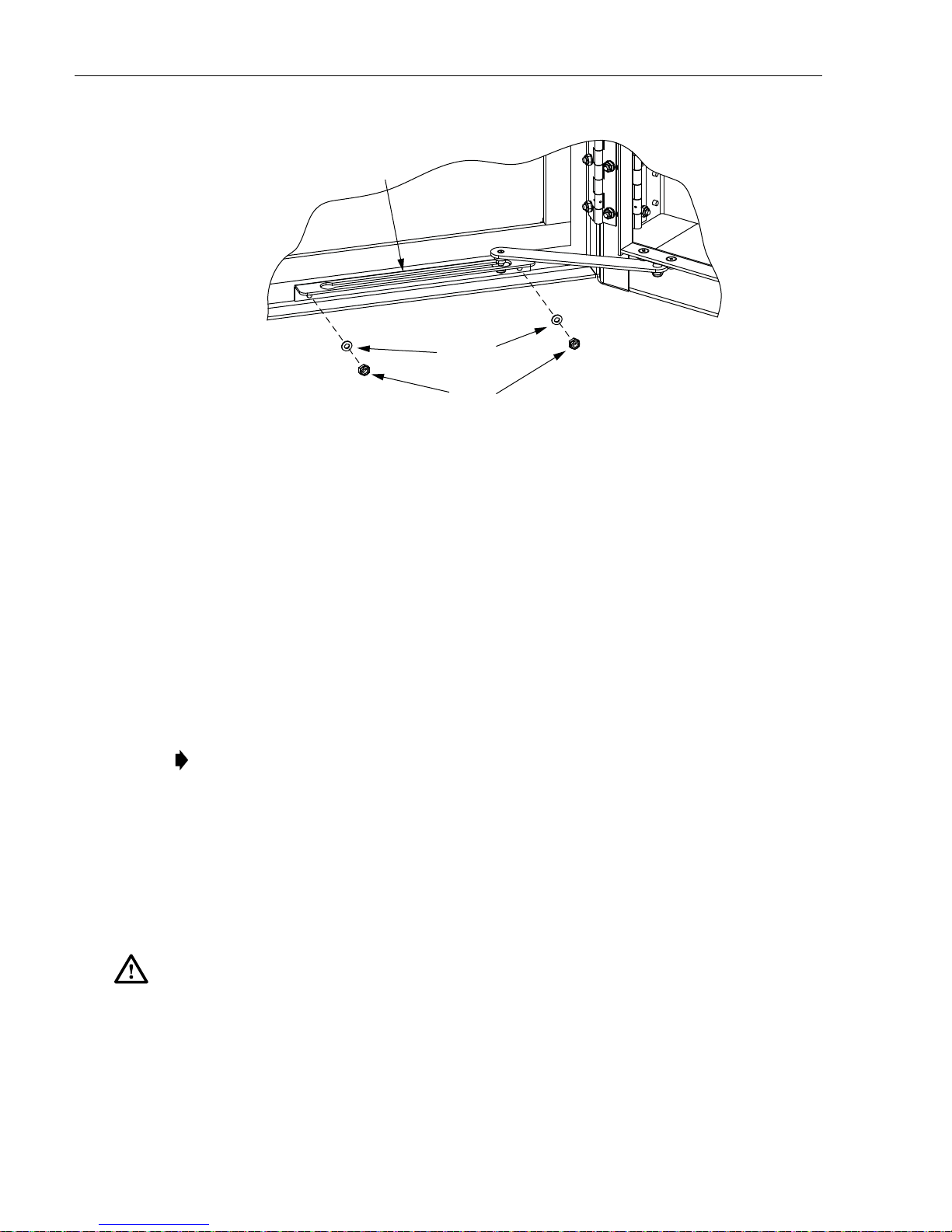
ADCP-96-139 • Rev B • July 2017
DOOR
BRACKET SLIDE
FLAT
WASHERS
LOCK
NUTS
Figure 51. Door Bracket Slide Hardware
10.7 Grounding System Terminal Access Procedure
Fiber optic cables with metallic strength members or shields are grounded to a common
grounding system. The grounding system is designed to allow the metallic elements of each
cable to be isolated for connection of cable locating equipment. The grounding system terminals
may be accessed through a small cover located on the rear side of the cabinet. Use the following
procedure to access and isolate the metallic elements of individual cables:
1. Locate the small hinged access cover at the rear side of the cabinet as shown in Figure 52.
2. Use the 216B tool to remove the screw that secures the access cover in the closed position.
3. Swing open the cover and locate the grounding stud that corresponds to the cable to be
located.
Note: A designation label is provided on the access cover for identifying cables.
22293-A
4. Remove the stud nut and disconnect th e cable so that it is not to uching the copp er bus b ar
assembly.
5. Attach cable detection equipment to the isolated grounding cable and complete the cable
location procedure.
6. When finished locating cables, reconnect the cable terminal to the grounding stud.
7. Tighten the grounding stud nut to 30 to 35 lbs force-inches. (3.4 to 4.0 Nm) of torque.
Warning: The grounding ca bles are connected to cabinet ground th rough the copper grounding
blocks. Failure to properly tighten the nut on each individual cable grounding stud could result
in improper grounding of the cable and result in performance or safety issues.
8. Close and secure grounding block access cover.
Page 54
© 2017, ADC Telecommunications, Inc.
Page 61
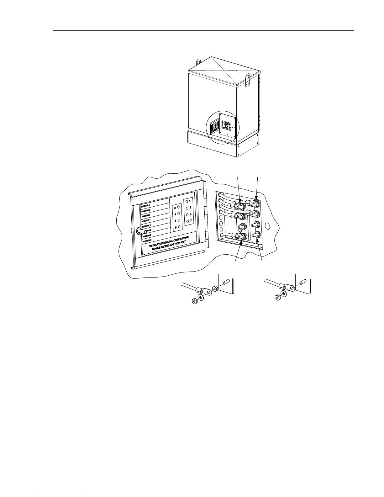
ADCP-96-139 • Rev B • July 2017
CABLE 1CABLE 2
TIGHTEN TO 30 TO 35
LBS FORCE - INCHES
(3.4 TO 4.0 Nm) OF TORQUE
CABLE 7CABLE 8
LEFT BUS BAR
CABLE ASSEMBLY
Figure 52. Grounding Block Access Cover
22687-A
RIGHT BUS BAR
CABLE ASSEMBLY
© 2017, ADC Telecommunications, Inc.
Page 55
Page 62

ADCP-96-139 • Rev B • July 2017
11 CUSTOMER INFORMATION AND ASSISTANCE
To find out more about CommScope® products, visit us on the web at www.commscope.com/
For technical assistance, customer service, or to report any missing/damaged parts, visit us at
http://www.commscope.com/SupportCenter
Page 56
© 2017, ADC Telecommunications, Inc.
 Loading...